HOLIDAY DONATION DRIVE - SUPPORT MSW - DO YOUR PART TO KEEP THIS GREAT FORUM GOING! (Only 13 donations so far - C'mon guys!)
×


johnhoward
-
Posts
162 -
Joined
-
Last visited
Content Type
Profiles
Forums
Gallery
Events
Everything posted by johnhoward
-
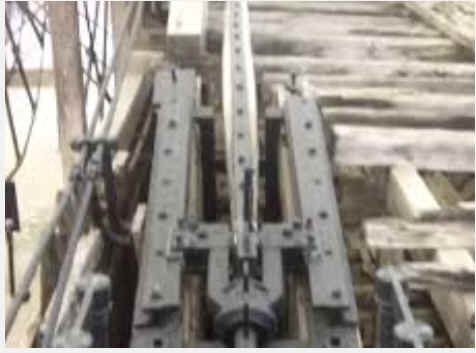
Pat, The twin rudders are surprisingly heavy especially in relation to their surprisingly flimsy looking tillers, but are based on their actual remains, recovered with the "USS Cairo" in 1963. Even so, they were reportedly relatively ineffective in controlling the ironclad on the rivers. johnhoward
-
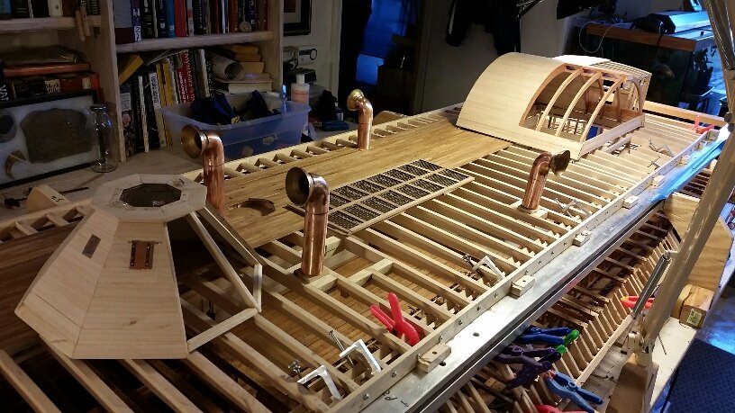
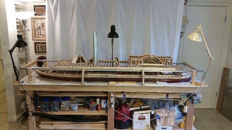
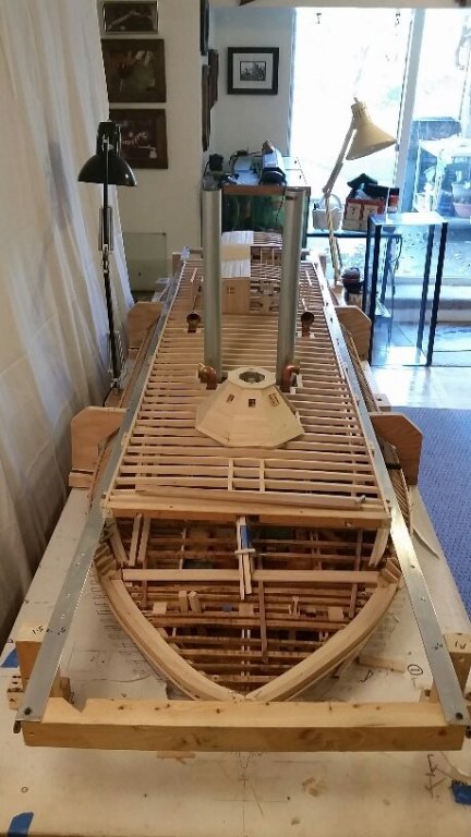
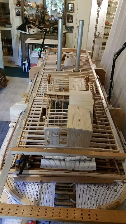
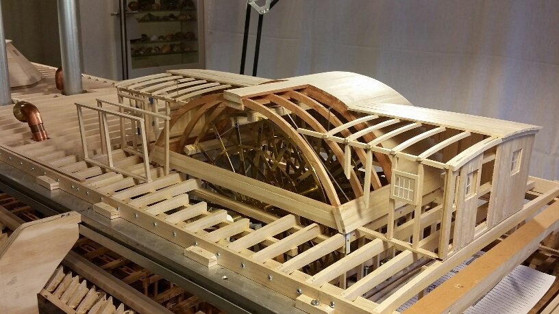
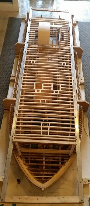
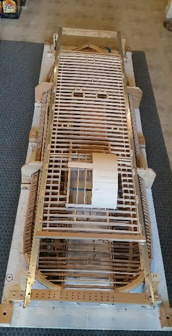
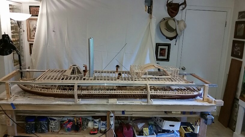
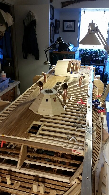
Sorry we haven't posted anything for the last few months (due to computer problems) but we continue to make good progress on our "USS St. Louis" Civil War Ironclad project as evidenced by the attached recent photos. The paddlewheel is nearly complete and we are finishing up the "Hurricane" deck elements and starboard side deck planking; much of the port side will remain un-planked to expose the model sub-structure and internal components. We are now concentrating on the fore, aft, & side casements, after-which the Hurricane deck and its temporary aluminum support frame will be removed for completion of the gun deck. I hope to be able to provide more details soon. johnhoward


-
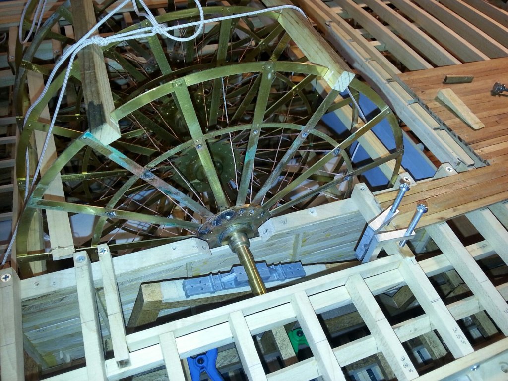
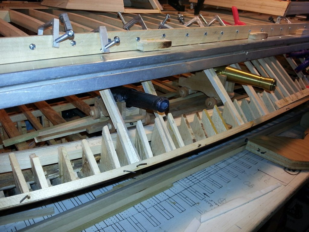
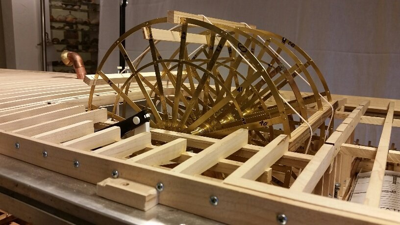
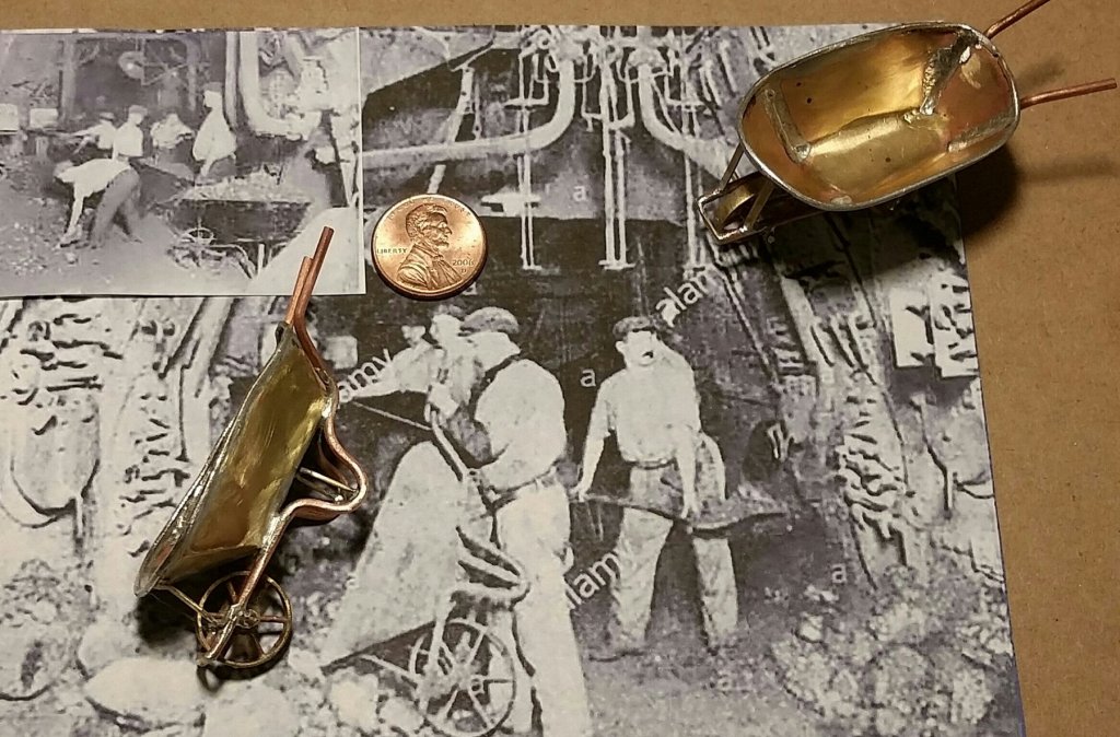
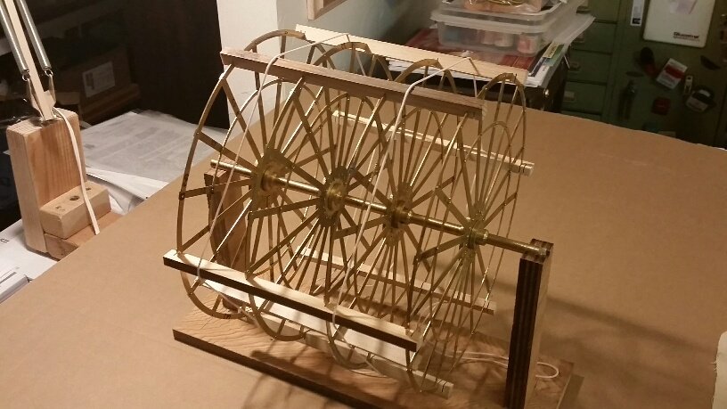
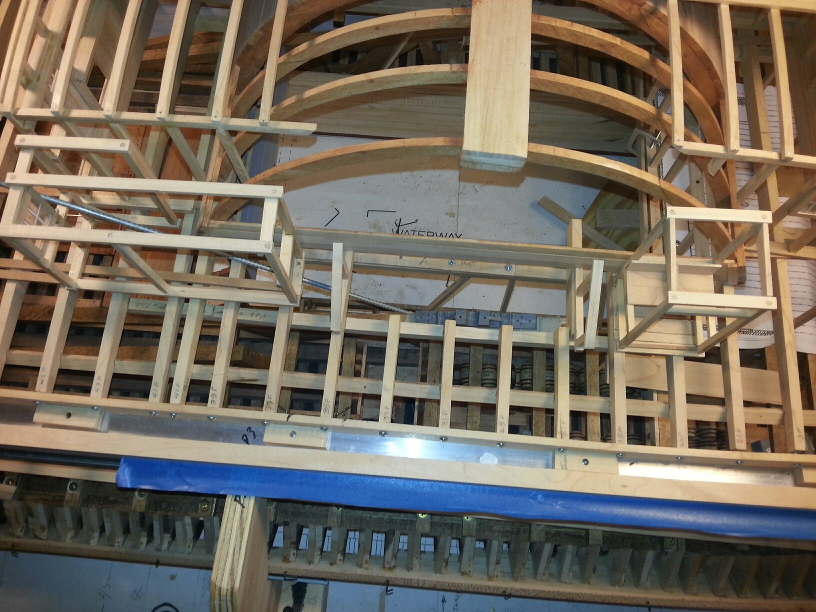
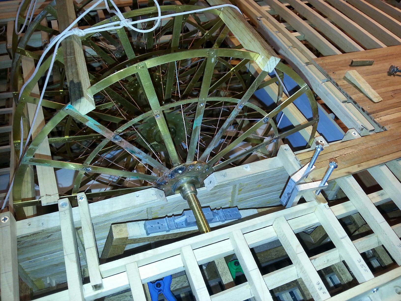
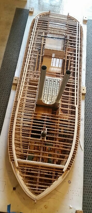
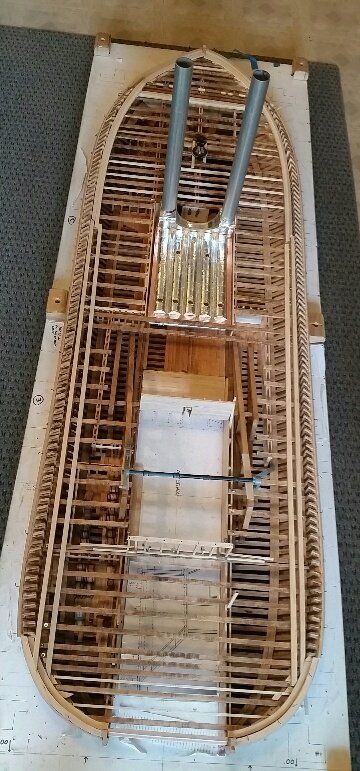
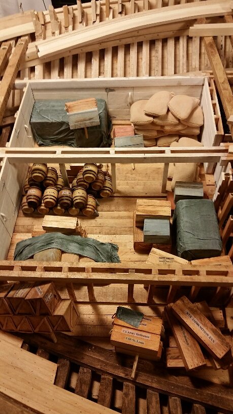
Attached are the most recent photos of our Shipcrafter Team's, "USS St Louis", City Class Ironclad model which primarily consist of a successful "dry-fit" of our partially completed brass paddlewheel with several of its thicker assembly jig boards still attached. When completed, it will include a "birdsnest" of thin rod cross-bracing between the four inner rings and all 17 "buckets". The actual paddle boards ("buckets") are inside of the larger paddlewheel ring (one is attached by its "U-bolts") as shown in the close-up photo. We are now working on framing for the skylight which covers the paddlewheel axle bellcrank and "pittman" arm attachment which penetrate the Hurricane deck. This demonstration allowed us to properly locate the two paddlewheel suppout ramps to achieve the correct paddlewheel axle location fore & aft while simultaneously achieving its proper vertical location which determined the depth of "bucket" penetration into the river water. Note that the paddlewheel is not in the center of its wheelhouse but further aft than center to achieve, in combination with the feed ramp, a smoother water flow to the wheel per "Pooks" original specifications. The starboard side of Hurricane deck houses have been roofed & sided, sliding windows are in place and the structural framing for the small attached sheds are also visible. Our brass models of the wheelbarrows for coal handling are based on late 1800's versions used for iron steamships. The 1:24 scale of this model allows us an exceptional amount of fine detail. johnhoward
-
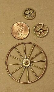
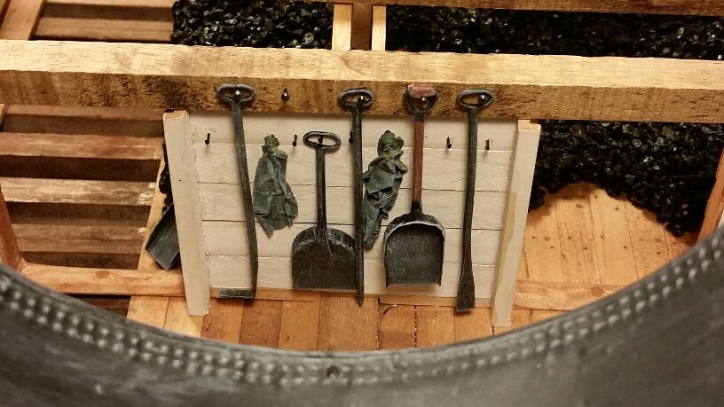
Attached are a few recent photographs of Bill's latest handiwork on our USS St. Louis Ironclad, [l to R: wheel for a coal wheelbarrow next to the previous wheels for the 12-pdr Boat Howitzer carriage, shovels & other tools in the fireroom, and the finished aft end of the boilers] Our modeling effort has been in a slight recess during August for vacations but should pick up again next month. johnhoward
-
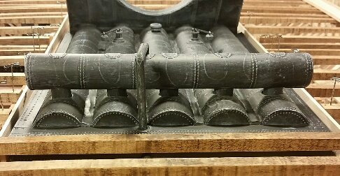
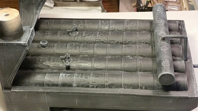
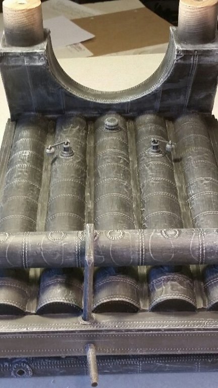
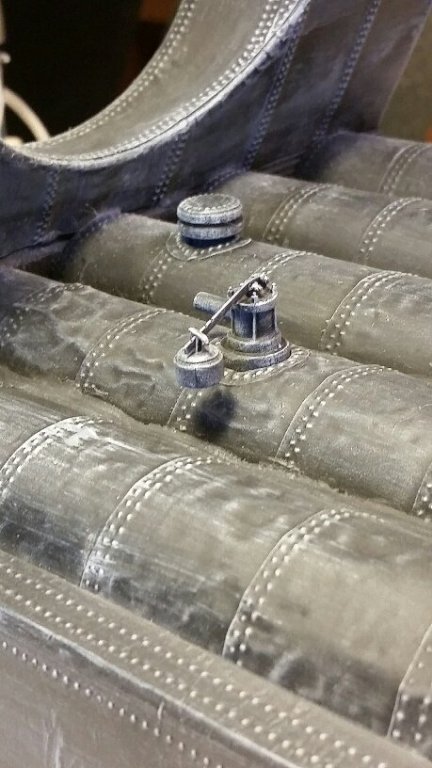
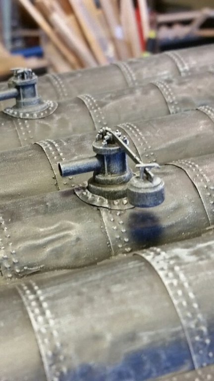
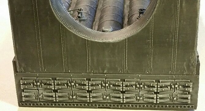
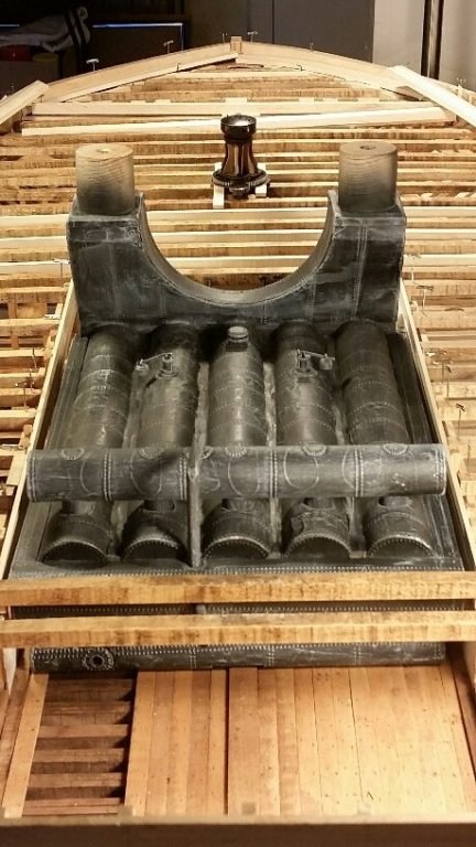
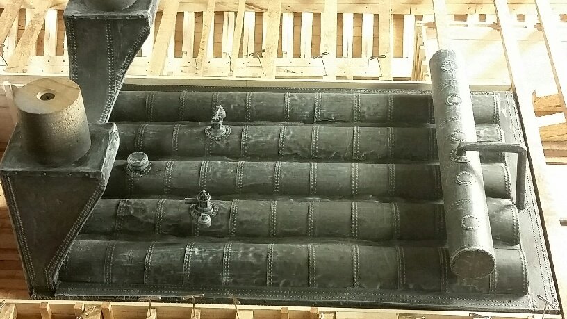
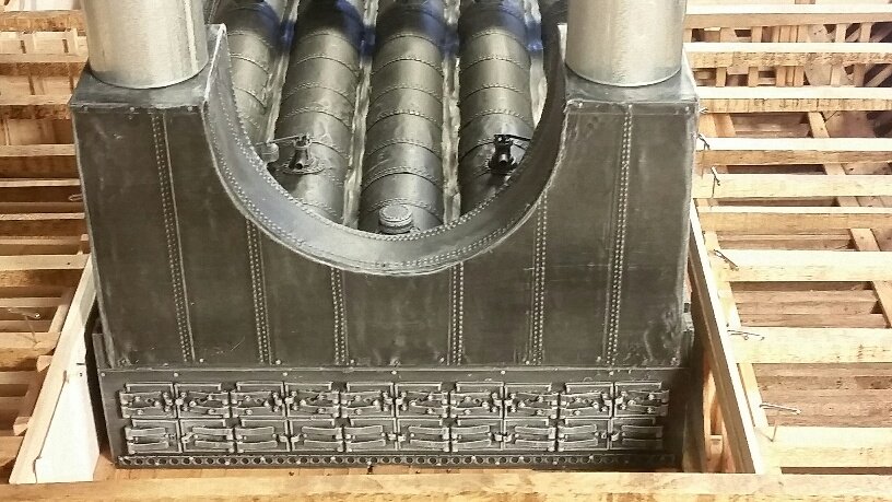
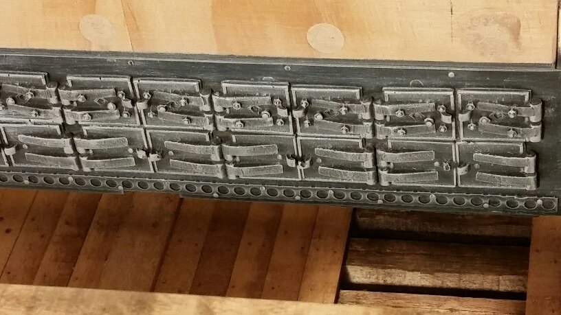
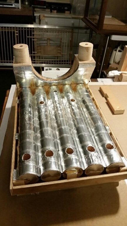
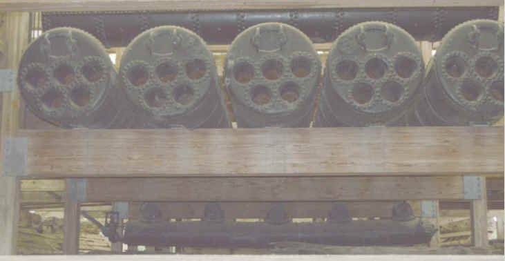
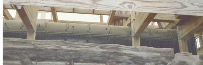
Attached are photos of our "USS St. Louis" ironclad flue type boilers/firebox and exhaust plenum recently completed by Bill. This model represents our reconstruction of the complete boiler arrangement for a typical Western River steamboat from about 1840 onward and was sized for our ironclad from the 5 boilers, steam drum, one of the mud drums, a few of the valves and 2 firebox doors actually recovered with the "USS Cairo" in 1963. The remaining more fragile elements such as the sheet metal covered firebrick bridge and sheet metal exhaust plenum apparently didn't survive or couldn't be reassembled. The model consists of a wood sub-structure covered by embossed metal foil sheathing and cast firebox doors with added individual relief and mud drum clean-out valves, all primed, painted and highlighted to correctly represent its exterior surfaces. High pressure steam from these boilers is fed to the two single cylinder main steam engines, the "Doctor" main auxiliary steam engine and another auxiliary steam engine which powered the capstan. johnhoward
-
Attached are recent photos of recent progress on our Shipcrafters' model of the "USS St. Louis" ironcladl. We are currently preparing to permanently lay the gun deck and separately finish the removable Hurricane Deck features. The boilers will be painted flat black and highlighted to reveal details. johnhoward


.jpg.8616478a44286685ff2a8f866b2d9830.jpg)
-
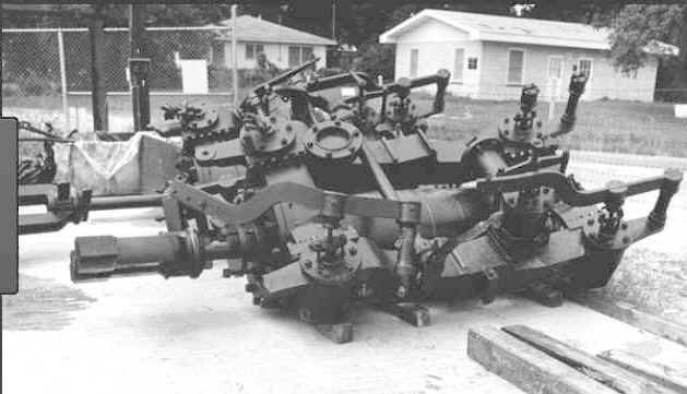
Gerhard, I found this interesting photo of the recovered USS Cairo's main steam engine just after it was cleaned up that may be of value in its modeling. johnhoward
-
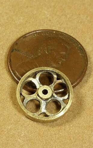
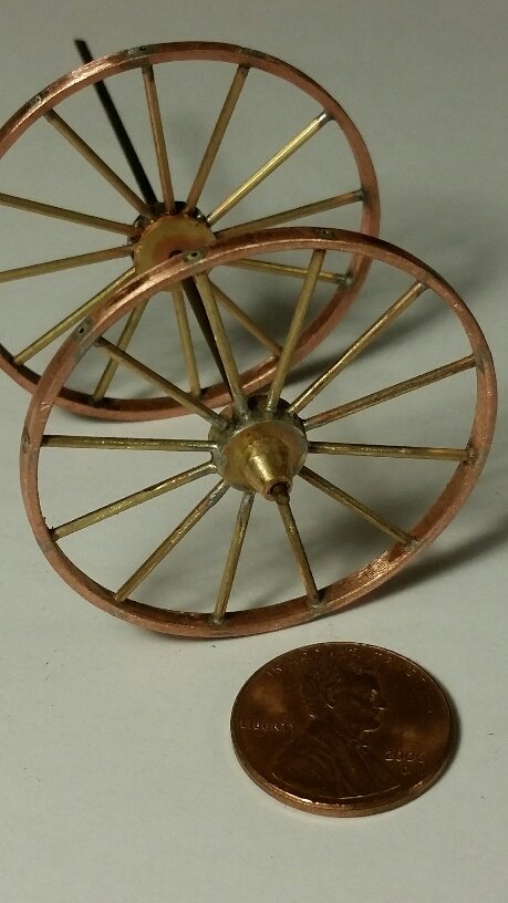
This is Bill's version of the rear wheel for the 12-pdr Boat Howitzer Carriage for our USS St Louis model. If you haven't seen it yet, take a look a Gerhardvienna's version for his USS Cairo scratch build live steam model at half this scale. It's really remarkable! johnhoward

-
Great job Gerhard, Bill just finished the rear wheel for 12 pdr carriage for our USS St. Louis model at 1:24 scale, twice the size of yours, which really shows how tiny your wheel really is. I'll post a photo on the USS St. Louis build sight. johnhoward
-
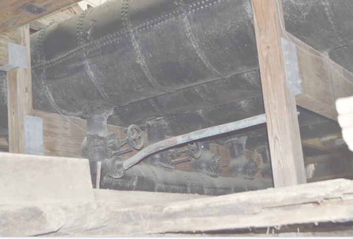
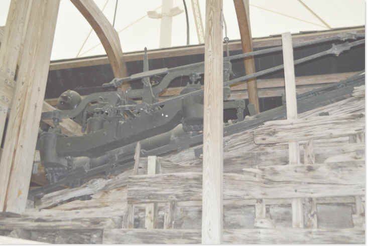
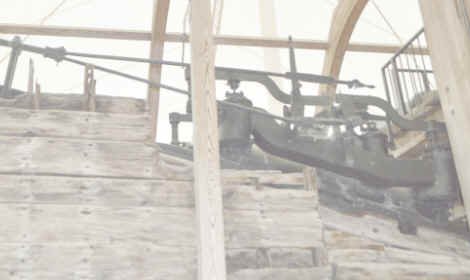
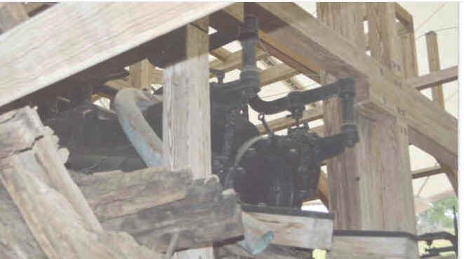
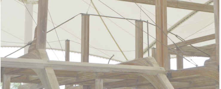
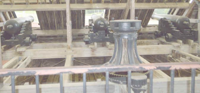
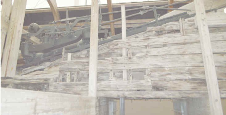
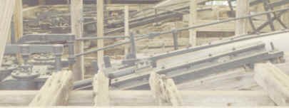
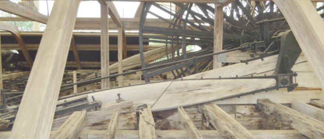
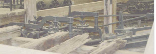
Thanks to Cher Petrovic we now have some unique views of the engines, boilers, capstan and other items from the lower perspective of the "USS Cairo" display at the NPS museum in Vicksburg, Mississippi. These will definitely help to clarify details of these components for our model of her sister ship, "USS St. Louis". johnhoward
.jpg.a65883a805b894bc76d33842aff799cd.jpg)
.jpg.c975b4ea1e7c07c0d8014a7146bca867.jpg)


-
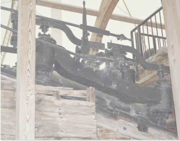
Gerhard, In response to your earlier request for Cairo main steam engine and Pitman Arm close-ups, I've attached the best photos that Cher was recently able to take at Vicksburg and a few others I have collected so far. Cher was able to get a special tour under the Cairo's remains and got a few shots I haven't seen before but some were originally pretty dark. We haven't started modeling the engines for our USS St. Louis ironclad but we assume that Eads didn't use a specifically designed engine for her, due to his short build cycle. The main difference from most contemporary sternwheeler steamboat horizontal engines is their installation on the 15-degree support ramp and consequent rotation of the poppet valves to a vertical attitude. Drawings of these details appear to be available on the internet. My plan is to eventually follow-up on old steam engine company records and archives to search for usable drawings. Perhaps information from the contemporary steamboat "Arabia" will be useful. Cher has also promised to provide us contact information for an old time employee/model-maker she heard about at the Cairo Museum, who may be able to help. johnhoward Steam Engine,Cairo..bmp Cairo Steam Engine.bmp

-
Gerhard, Problems like this are the main reason we are trying to document misleading information or conflicts between published data for the "City Class" ironclads so the modeler is aware of them before spends a lot of his valuable time. I applaud you for striving to achieve the highest degree of accuracy possible in your model. johnhoward
-
Gerhard, Nice photo of the Cincinnati. I'm pretty sure it is post-Civil War and the 5 aft casement windows were added then to relieve excessive heat when it was safer to have openings in the side casements. We have also wondered about the structure or "trunk" on the aft casement and our best guess is that it was a chicken coop. One of the small stacks between the funnels is most likely the cook stove smoke stack which is directly below on the gun deck. I don't think they would be engine exhaust which reportedly vented directly to the main smokestacks and are located a long distance away for such a small stack. One of them could have been a steam whistle but I haven't ever read anything about one. The 4 ventilation funnels show pretty well in this photo of the USS St. Louis model; 2 are just forward of the main smokestacks and 2 are just forward of the wheelhouse. They also show up in numerous contemporary photos but can be confusing to locate because they can be rotated and elevated to best catch the prevailing wind direction. Most drawings of the USS Cairo that I've seen also show them on the hurricane deck but their exact locations vary a little. johnhoward USS Baron DeKalb(2).bmp
-
Gerhard, The 16+ ventilation openings I am referring to are the small multi-use hatches on the gun deck which had both wooden and grate covers for either access to, or ventilation of, the lower hull areas. We will be modeling some with each type of cover in place and probably a few simply open. The framing and covers for these openings were flush with the deck so they didn't obstruct the cannon carriages and normal crew activities. Our assessment of the ironclad access & ventilation concluded the following: We believe that there must have been more access hatches between the hurricane deck and the gun deck than shown on existing drawings (possibly they were within the deckhouses). The only known hurricane deck hatch is inside the pilothouse and the only other inter-deck access is via the ladders on the bow and stern casements. The forward small skylight probably also served as a hatch for commissary stores loading. The small hatches on the fore and aft decks are pretty far away from the hubs of activity to be much value. Most of the stores loading & ventilation must have been accomplished thru the gun ports. The four ventilation funnels only extended thru the hurricane deck and not thru the gun deck. After the Civil War some of the surviving ironclads such as the USS Cincinnati were modified to add openings in the aft side casements, which would have been extremely hot without any gun ports, as seen in some contemporary photographs. The USS Cincinnati had been sunk twice and recovered, which probably explains these modifications. Have you discovered any others? johnhoward
-
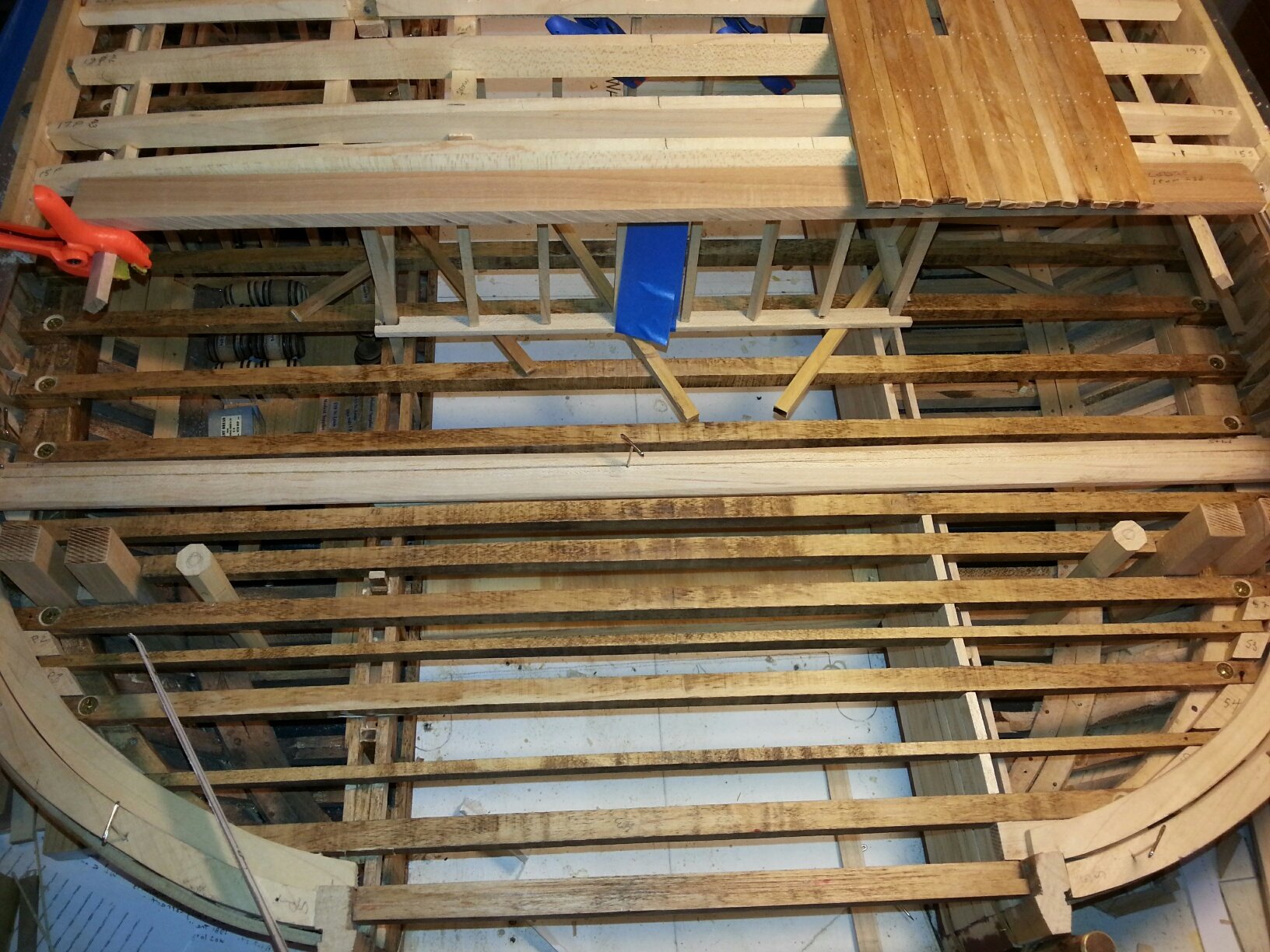
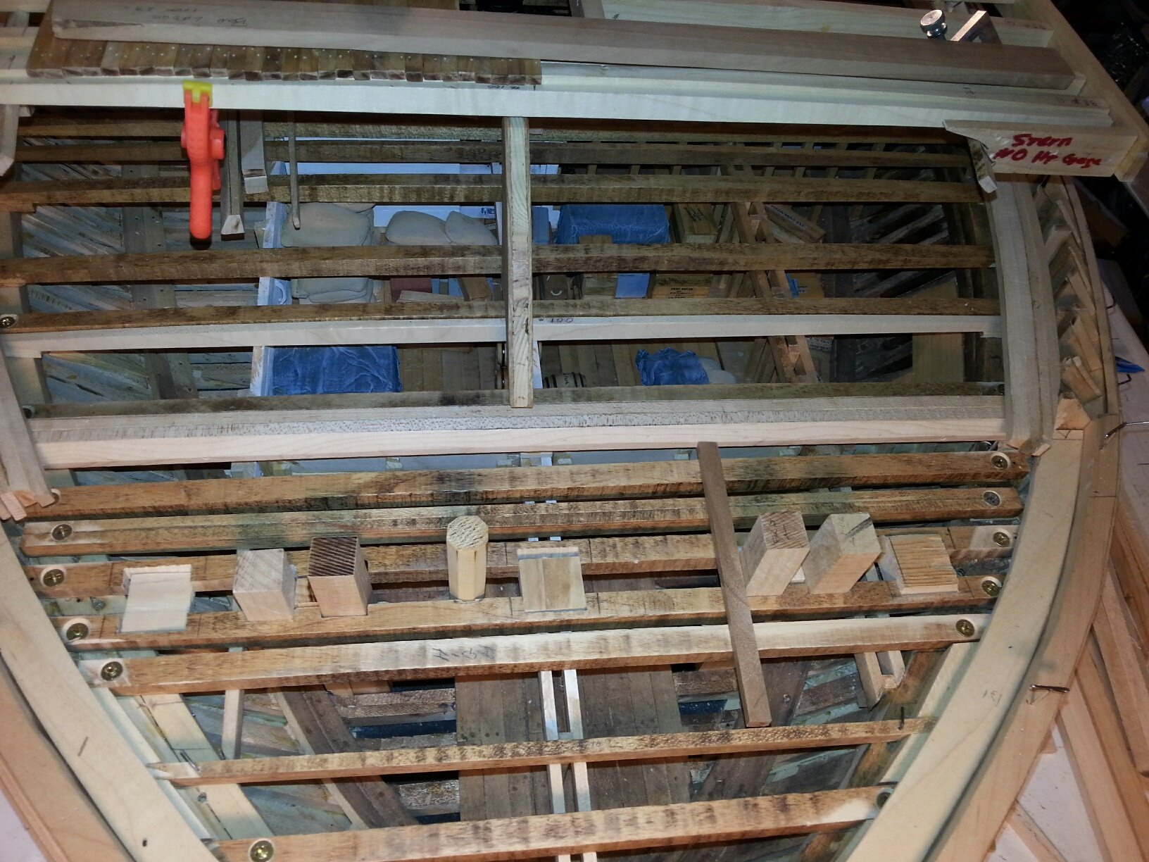
Attached are today's progress photos for our USS St. Louis ironclad model which include installation of the fore and aft deck margin planks and a dry-fit of the hurricane deck "ventilation" grate. It should be noted that, on most "City Class" ironclad models and drawings, this grate is erroneously fabricated as, or referred to as, a "skylight", similar to the small glass paneled skylight in the far forward part of this deck. Besides the fact that the only objects beneath this grating are the five hot boilers enclosed by louvered walls, which wouldn't particularly benefit from any great amount of light, Samuel M. Pook's original gunboat specifications for the "Hurricane" deck states as follows: [Quoted from the NPS Vicksburg Historic Structural Report(HSR)] "There shall be an opening in this deck eight feet wide fore and aft the boat for ventilation; a coaming will be formed around this opening three inches above the deck and six inches thick; there will also be a center piece of the same height fore and aft the opening, over each beam a thwartship piece will be fitted and fastened to the beam; the whole will then be covered with grating." For our 1:24 scale model this ventilation grate is fabricated from pearwood frames and "1/8-inch hardware cloth" (galvanized wire grating) which could be walked upon, if necessary. The grate will ultimately be fastened atop the Hurricane" deck planking. In actual practice, this grating would ventilate the excessive lower deck boiler heat. Awnings were fitted above this deck, primarily for protection from the sun in the Southern USA, but would also provide protection from excessive rain. All of the other 16+ small gundeck access/ventilation openings will be similarly covered with 1/8-inch grating and wood panels. The fore & aft deck margin planks will either be "nibbed" for the deck planks, or the deck planks themselves will be beveled in accordance with standard shipbuilding practice. johnhoward
-
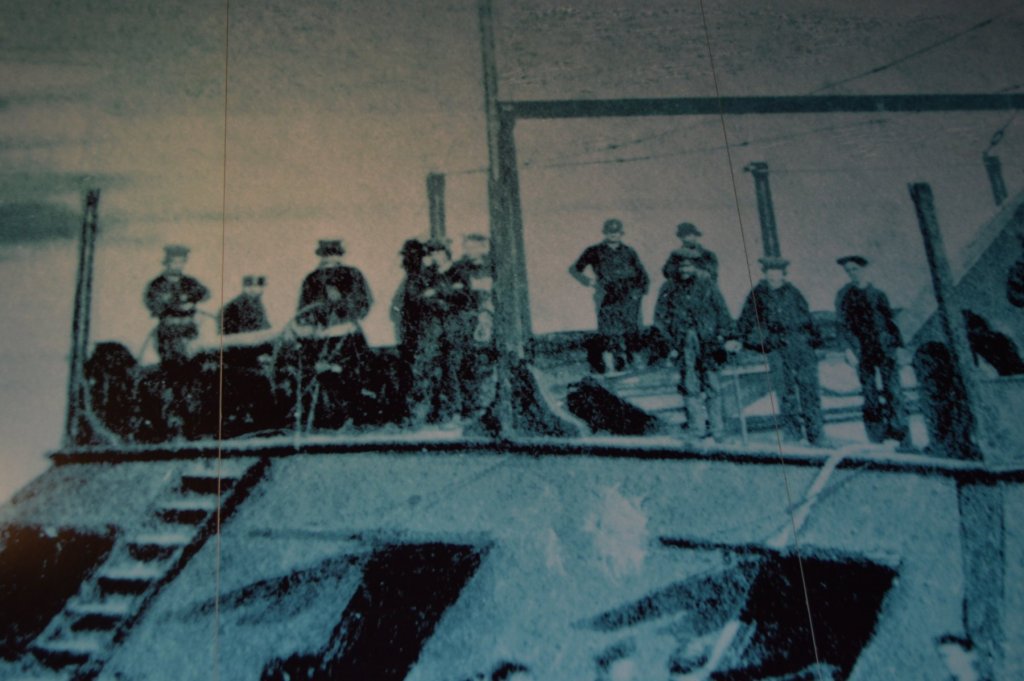
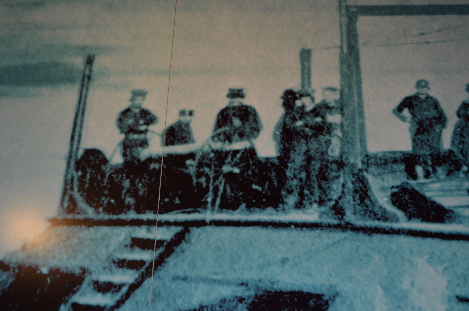
Attached are close-ups of the USS Cairo Museum mural, courtesy of Cher Petrovich who recently toured at Vicksburg, clearly showing the 12-pdr Howitzer on the hurricane deck and some recent photos showing progress on our 1:24 model wheels for it, our overall USS St Louis model, the wheelhouse, and a dry-fit of the stern deckhouse framing with its sliding window. We are currently forming and installing the waterways and margin planks for the gun deck in preparation for additional deck planking. If you look carefully at the overall model photo, the steering wheel and pilot are visible inside the pilothouse which will later be covered with armor plating. johnhoward


-
Hi Gerhard, Attached are the first of many photos we just received from Cher Petrovich, member of the Missouri Civil War Historical Society, author and professional photographer, who visited the USS Cairo Museum at Vicksburg, Mississippi last week and was responding to our list of requests. These are much clearer photos of the museum mural showing the 12 pdr howitzer and light carriage on the USS Cairo hurricane deck. By the use of her credentials, our photo request list, and other artwork & photos of our USS St. Louis model, Cher was able to get a private tour of the USS Cairo into areas inaccessible to usual visitors. Some of these were in areas with insufficient lighting for good photos which we are attempting to brighten up to be more useful. She was able to get closer access to the main steam engines and I will post them for you as I sort them out. The NPS has not yet appointed a new curator for the Museum but she made contact with several other employees, including a model maker, who may be a good source of additional detailed information. I will keep you advised of our progress. As you can see these are very high quality 8.8 mb photos. johnhoward

-
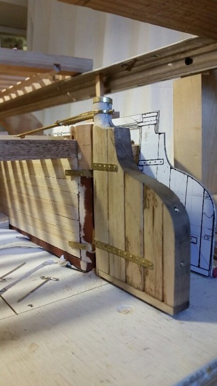
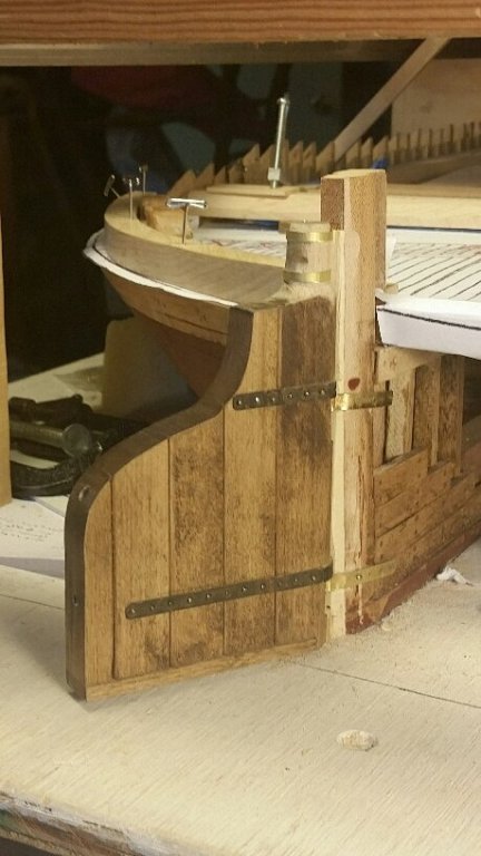
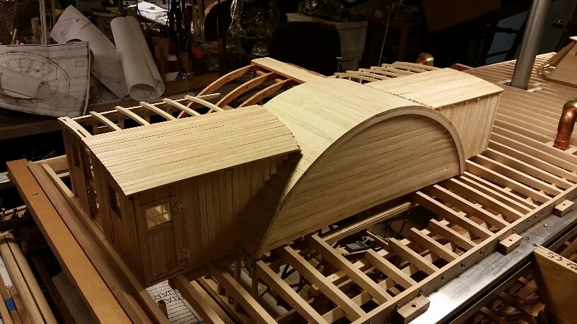
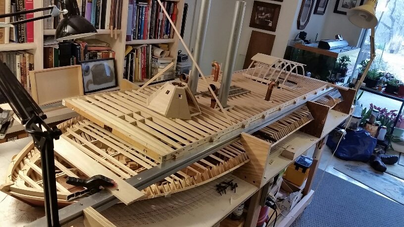
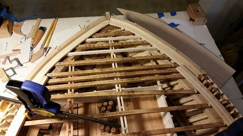
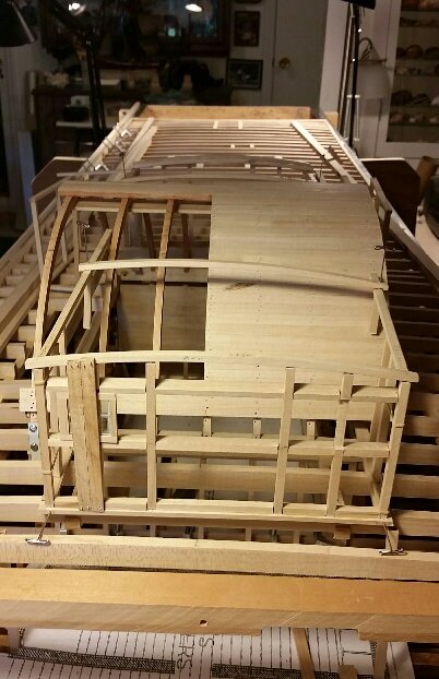
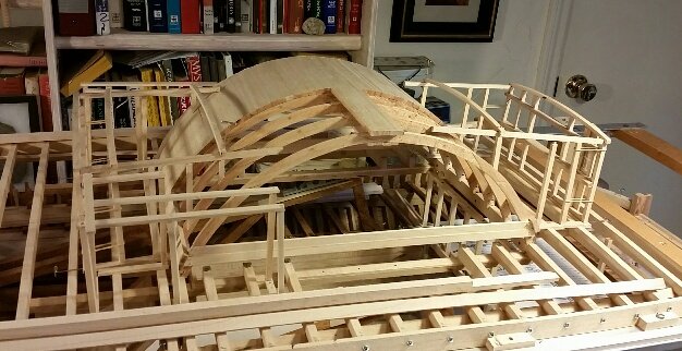
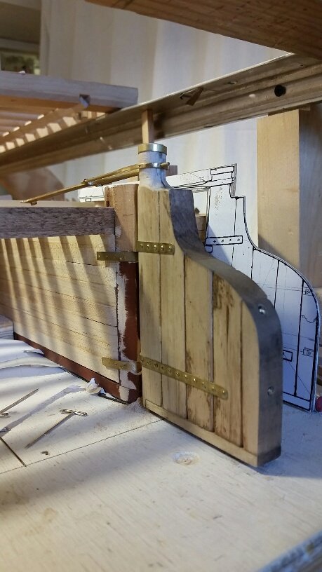
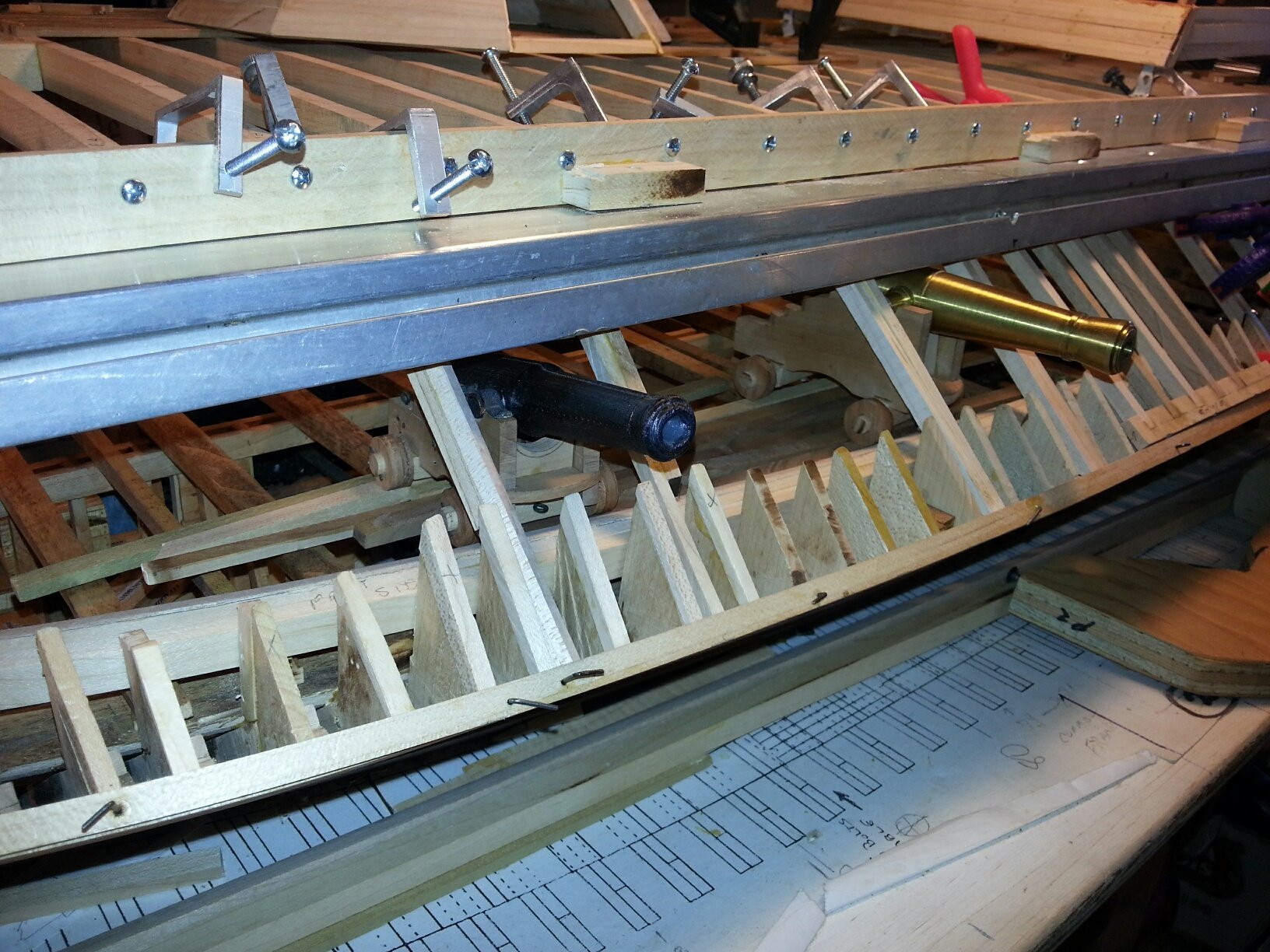
Attached are recent photos of activity on our USS St. Louis ironclad model. The first 2 show the structural framing for the aft Hurricane deck house with a prototype sliding window. A more delicate & realistic version of this window is under construction. The forward deckhouse and four smaller sheds are also under construction and will complete this structural assembly The purpose of this dry-fit was to verify its mate-up with the wheelhouse arch. The starboard side will eventually be completely planked while the port side will remain unplanked similar to the wheelhouse.. The other photo is a dry-fit of a prototype 32-pdr cannon & carriage at one of the port side gun ports. It is resting on a small temporary section of gundeck planking. The cannon barrel is Bob's 3D printer version which will be replaced by Tom's brass machining, currently in work The purpose of this dry-fit was to verify structural clearances including the gun port sill which was 24" above the deck. This side of the model will remain relatively open to reveal the structure while the starboard side will be completely finished johnhoward
.jpg.1f18179b732b6a0d0deb34363032f84b.jpg)
.jpg.35c235f47bbf763abceabd057990ce8a.jpg)
-
Thanks Gerhard, I've forwarded your requests for engine detail photos and we should see the results by Monday. johnhoward
-
Gerhard, I have been contacted by a member of the Missouri Historical Society here in St. Louis who is traveling to Vicksburg this coming weekend and has offered to take any specific photos at the USS Cairo museum that we may desire. I have asked for a close-up of the 12-pdr on the hurricane deck of the USS Cairo mural that we previously discussed and a few other items we need. If you have any other photo requests, I will be glad to forward them as well. Regards, johnhoward
-
Gerhard, I determined the deck house roof camber from measurements taken the stern view photograph of the USS DeKalb{USS St. Louis) that I posted earlier. When adjusting these measurements to our 1:24 scale model beams [8" length, .35" camber], the radius of the roof beam calculates to be 22.8". If you accept these measurements, for your 1:48 scale model the roof radius would be 11.4" for beams 4" long and .175" camber. I have never seen any specifications for the City Class Ironclad deck and roof cambers, however historical maritime vessel construction practice shows that the camber dimension increases and the radii decreases as the deck level rises, which is consistent with the photo. johnhoward
-
Thanks Eric, I accidentally found your site from other communication with Gerhard(Vienna) and am glad I did. In a way you are experiencing a lot of the same problems that we are having in the research department. We have a lot more information on the USS Cairo/USS St. Louis but our problem is that a lot of it is incorrect or conflicting. We have a lot of new photos but only the metal parts have really survived and the old photos only show a pile of junk.. Most of the rest is from best guess reconstruction. Standard Western River Steamboat practices like yours for the Arabia are a much more reliable resource and we track down every lead we find in this area. We have amassed a tremendous amount of information but are conflicted between finishing the model and documenting it as we go. Before we had realized the inconsistencies in the published USS Cairo data, we had estimated model completion in 24 months for the Missouri Civil War Museum (MCWM) at Jefferson Barracks, which has now already assigned a display room and built a case for it as the room showcase. At the last minute the Museum owner and curator also requested the model be built to twice the originally planned 1:48 scale and we accepted without fully realizing the resulting model volume increase and amount of additional detail this would entail!. We are now in our 33rd month and have at least another year to go. We will gladly share any information we have acquired. Please let me know if you are ever in St. Louis and desire to see the model or any of our data before we deliver it to the MCWM. johnhoward
-
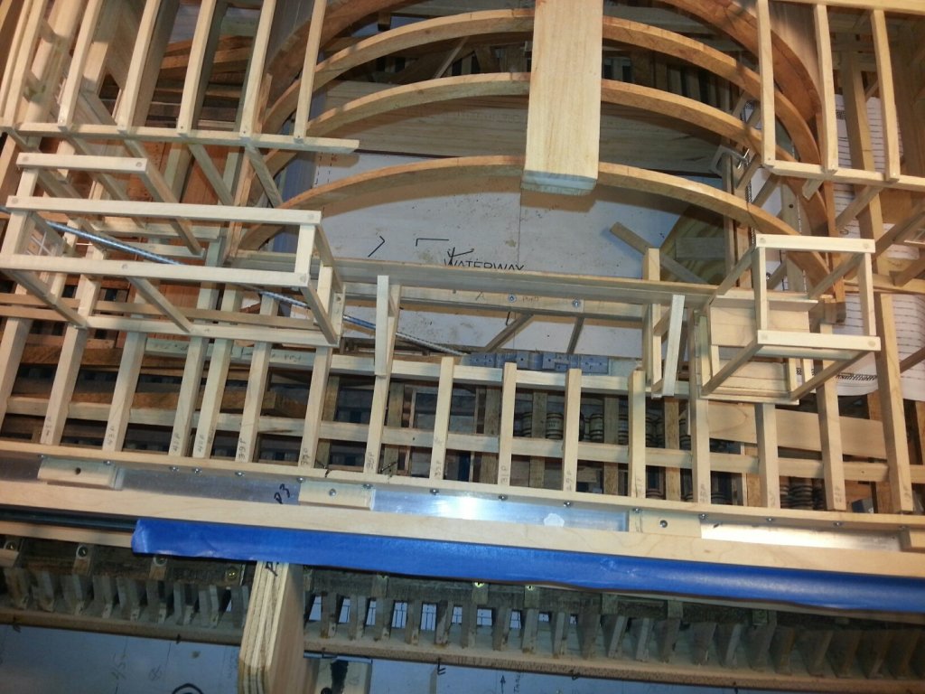
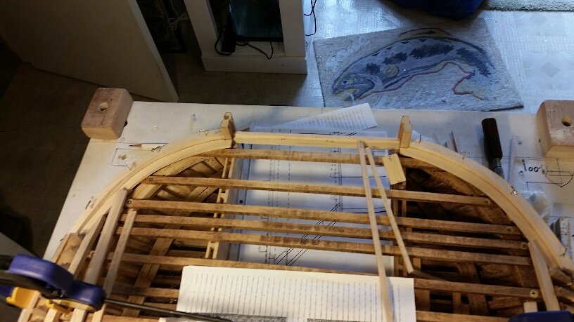
Construction update: Mockup of the Hurricane Deck House structure for the USS St. Louis continues with the addition of the first cambered roof beams. These were made from .20" x .75" x 8" hard maple stock blanks using a two-piece sanding jig, which was previously sawn to the calculated radius of 23.75" to reproduce the roof camber for our 1:24 scale model. After removing waste wood from the convex side using a band saw. the blank is guided through the belt sander using the two piece jig to form the final convex contour. The second step is to use the concave half of the jig to back up the remaining contoured blank as it is progressively fed into a drum sander to form its concave side until the desired beam depth of .17" is achieved. The general sanding sequence is depicted in these photos. This basic method was also previously used to create the cambered gun deck and hurricane deck beams. johnhoward
.thumb.jpg.ef1bafb32372e2f8230fde9bbf025dad.jpg)
.jpg.eb8bd7d6fda3f62326f333c2a5dd5ae5.jpg)
.jpg.18ee23ae2e86dae48501985aaea0fba0.jpg)
.jpg.85f9140adb92b4467102e2b0a9f70e03.jpg)
.jpg.51140c7b489a0540f661d5d9ed9eb669.jpg)
.jpg.ef69d6387a8e39d8b926bde1318e4ec6.jpg)
.jpg.55029a570492f82fdb9697f4c65cc55d.jpg)
-
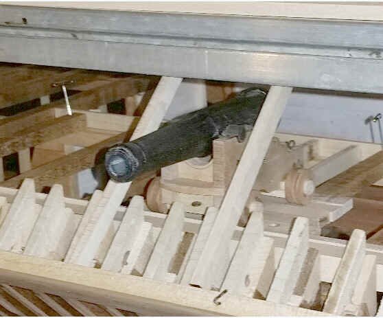
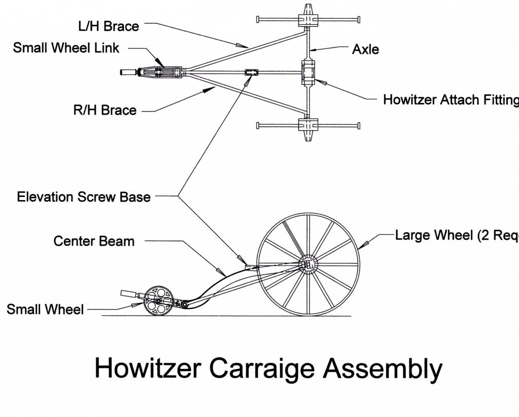
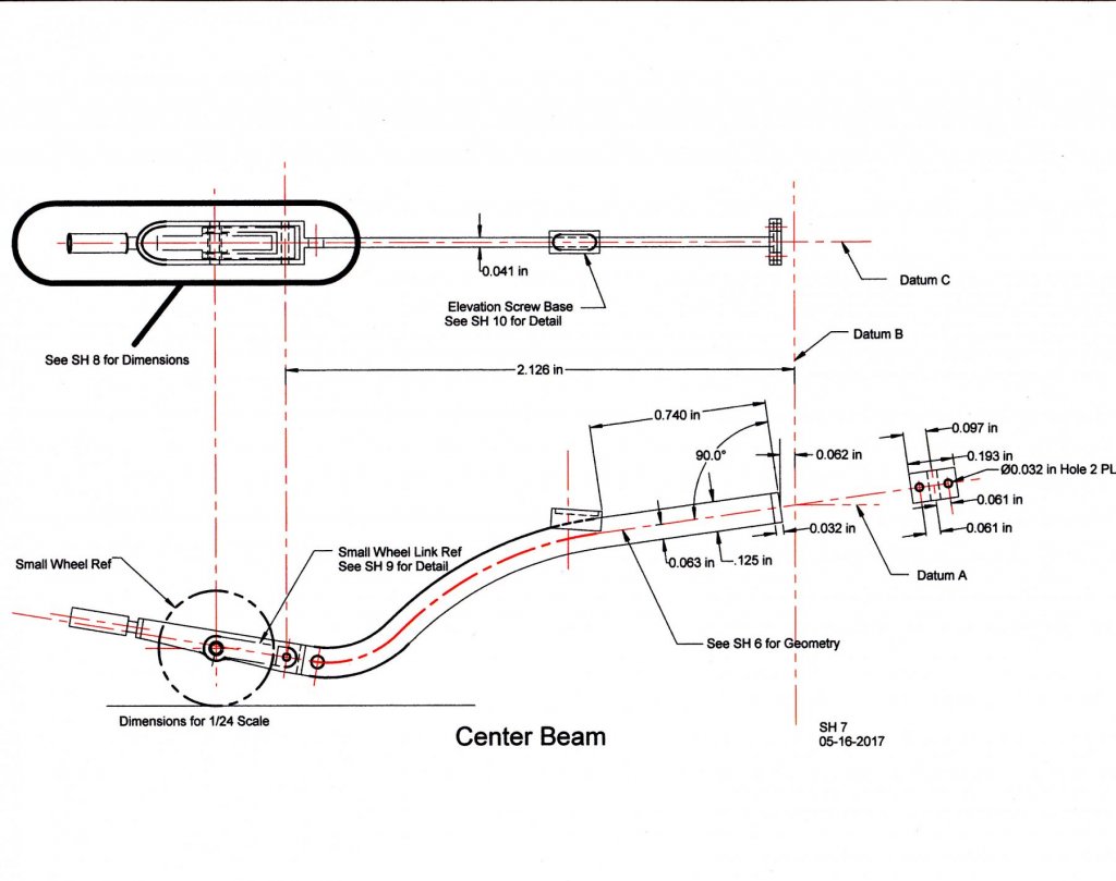
Attached are a cfew of our the TurboCad drawing sheets for the 12-Pdr Boat Howitzer which we are modeling for our USS St. Louis ironclad. Gerhard, The most obvious differences on our version appear to be the lighter 12-spoke main wheels & the articulating trail wheel which permits the frame to rest on the ground to absorb recoil during firing. johnhoward Howitzer & Carriage- SH 15.pdf
-
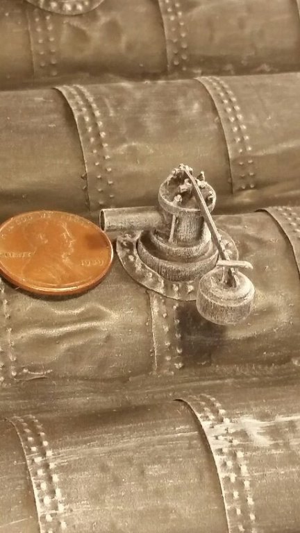
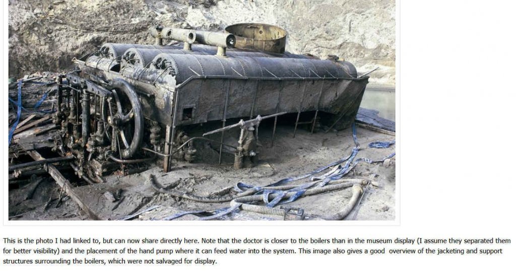
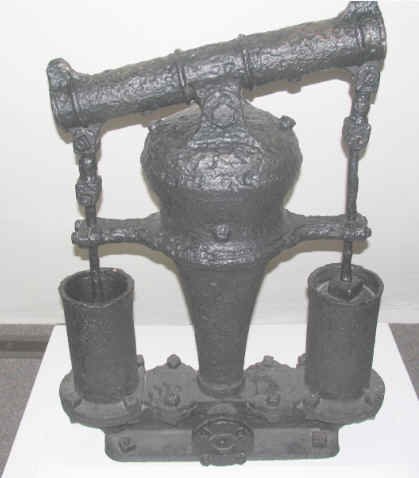
Thanks to Eric's "1856 Missouri River Steamboat Arabia log", another mystery for the USS Cairo/USS St. Louis appears to be solved. The photo of a "bilge pump" on the far right was taken at the USS Cairo Museum at Vicksburg , Mississippi and was apparently recovered from the Cairo but its original location was not reported. The photo on the left depicts a "Doctor" auxiliary steam engine and the boilers, connected to a very similar "bilge pump" from the steamboat "Arabia". The center photo is our model of the bilge pump for the USS St. Louis. Eric states that "... when firing up the boilers cold, the engineer & crew would use a hand pump to add sufficient water to the boilers to allow fires to be kindled, then once the boilers were up and running, the steam lines from the boilers were redirected to get the "Doctor" running" (which would then take over supplying make-up water to the boilers. The hand pump's globular section was apparently a reservoir for the start-up water and was below the waterline which kept it filled..) This makes perfect sense so we will now plan to locate the bilge pump adjacent to the "Doctor" on the feed water ramp immediately forward of the paddlewheel on our model of the "USS St. Louis". johnhoward
.jpg.7f0bdc0f7ac64d03ff55536c9d614418.jpg)


.jpg.3ed9b1a678dc63cf1ea78d686aeb551f.jpg)