HOLIDAY DONATION DRIVE - SUPPORT MSW - DO YOUR PART TO KEEP THIS GREAT FORUM GOING! (Only 13 donations so far - C'mon guys!)
×


johnhoward
-
Posts
162 -
Joined
-
Last visited
Content Type
Profiles
Forums
Gallery
Events
Everything posted by johnhoward
-
That's great Gerhard, The whole idea of starting to release the results our research for the USS St. Louis as we go along was to identify the errors before modeler's wasted a lot of their time. I totally understand that you can't afford to go back and redo everything. It is a shame that so much USS Cairo misinformation has been repeatedly published by otherwise reputable sources, apparently without much checkout. We have been trying to complete the research for each element before we build it but, we too, have fallen into the same trap. johnhoward
-
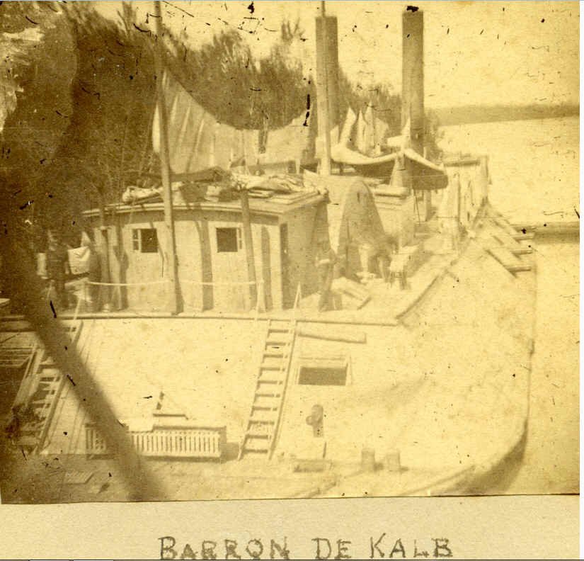
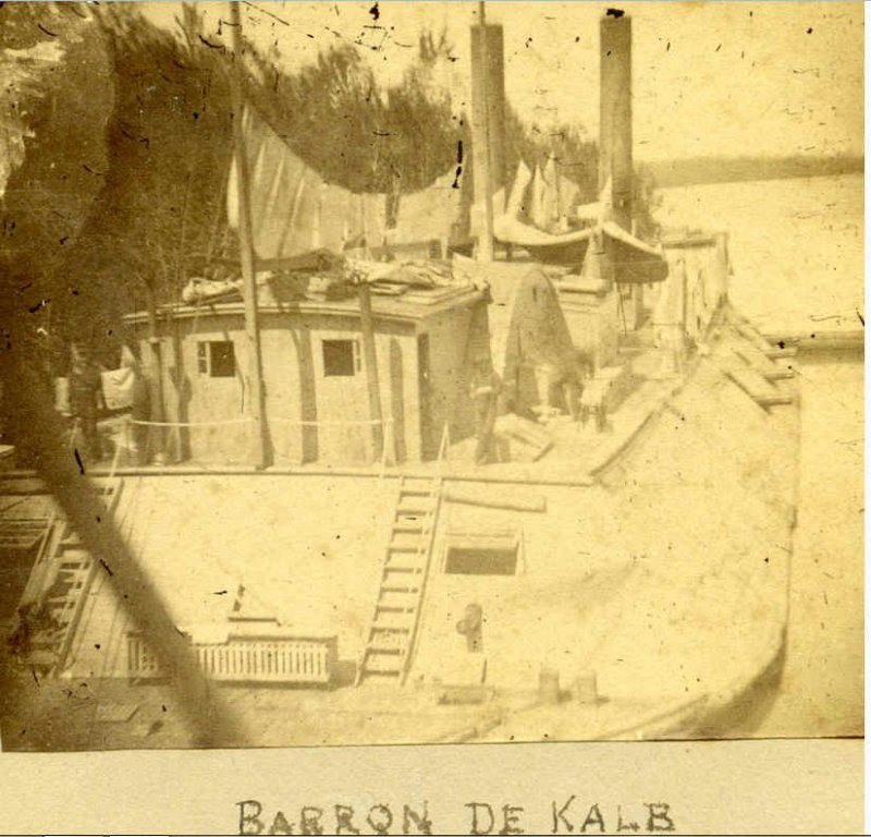
Gerhard, Attached is one of the contemporary photos I was referring to in my previous message. This is identified as the "USS DeKalb" which was originally the USS St. Louis and clearly shows the deck and roof cambers and window arrangement. The Dekalb was sunk in 1863 so this can't represent some post-Civil War peacetime modification. All decks and roofs were similarly cambered to shed rain water and accumulation of snow to the scuppers. johnhoward
-
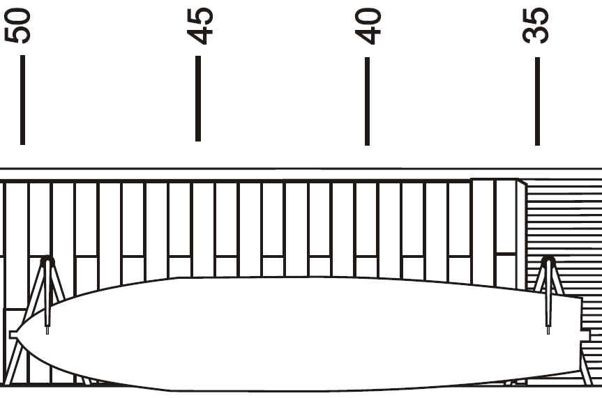
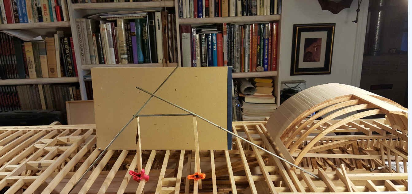
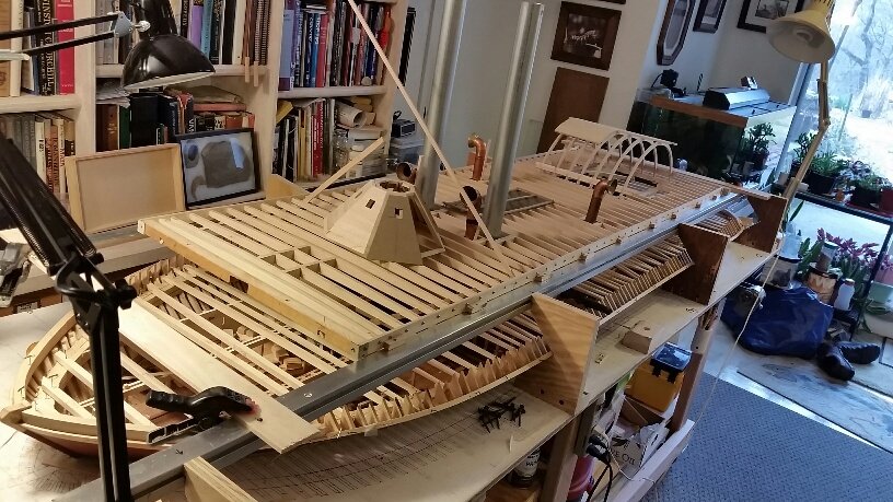
Attached are photos of recent activity covering the planning for items to be located on the Hurricane deck for our model of the City-Class Ironclad, "USS St. Louis".. The first photo depicts a mock-up of the port side "Hog Chain" (Cable) which runs from the forward hull floor frame at station #73, over the two support posts (which extend down to the outboard keels) and then aft down to the hull floor frame at station #21. The mock-up rods will eventually be replaced by continuous cables for the port and starboard "Hog Chains". The "Hog Chains" were obviously required to help support the aft twin hull booms which straddle the paddlewheel and tended to "hog" due to insufficient buoyancy. The path of these "chains" through the lower hull framing is amazingly tight but tends to verify the accuracy of the hull framing drawings. The second photo represents the first step in a layout of the aft Hurricane deck-house which is incorrectly depicted in most of the existing "USS Cairo" drawings and models because they lack the deck-house roof camber and the Hurricane deck camber. The Hurricane deck camber is already included and when the roof camber is added to this layout, it will clearly intersect the straight ridged wheelhouse roof in an arc (in its plan view) instead of a straight line. In addition, the twin stern facing doors will be replaced by two smaller sliding windows which are all clearly visible in contemporary photos of the "USS St. Louis" (Baron DeKalb). johnhoward


-
Gerhard, You have the correct stove configuration. Attached is some of the information we used to model and locate our cook stove and exhaust vent for our USS St. Louis model. For confirmation, we also contacted the supplier who built the stove replica for the Cairo Museum at Vicksburg. johnhoward Cook Stove Location on NPS plan.bmp cook stove & boilers,USS Cairo.bmp Cook Stove-Cairo(4).bmp Vent,Cook Stove,Cairo,Questionable.bmp
-
Gerhard, I don't know if you have seen them but the battery powered flickering candles provide the perfect effect for kerosene lamps. We had planned to use them but our museum doesn't want any power in their cases. Too Bad! johnhoward
-
Gerhard, Your decisions on the glass and hinges sound reasonable. I would make the whole exterior of the USS Cairo flat black or dark gray to minimize visibility on the rivers at night. You wouldn't want any bright contrasting trim which would attract attention. However, I think the interior surfaces should lighter gray or even "whitewash" to retain reflected light thereby providing the crew with maximum visibility in the dark spaces which were only lit with flickering candles or kerosene lamps. This is the general color scheme we are using for our USS St. Louis. Blackout of interior lighting while on patrol would also be strictly enforced. These ironclads were always dangerously close to the river banks and enemy snipers or more powerful weapons. johnhoward
-
Hi Gerhard, I don't think the skylight over the boilers was glazed or hinged as its main purpose was to vent heat overboard from the firebox and boilers. Pook's specifications for the City Class ironclads simply specifies a flat grate which has a coaming about 3-inches above the deck. They probably covered the grate with a tarp when moored with the fireboxes shut down. The forward skylight was most likely glazed and hinged as it provided light to the deck below and was probably also used as a hatch in the hurricane deck for loading foodstuff into the Commissary Room below the gun deck. johnhoward
-
Thanks Gerhard, The only other stack I've found is for smoke from the cook stove. johnhoward
-
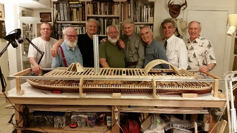
Gerhard, Antony, Thanks for your nice comments. The participants in the photo, left to right, are: Fred Hecker, Tim Jovick, Tom Stahl, Vince Murphy, Howie Smith, Bob Keeler, Dr. Mike Orgel, & Bill Kammermeyer, [Scott Safranski was missing] Gerhard, I'm not sure I totally understand your question on the City Class funnels but I've attached my reconstruction of the corrected propulsion system schematic (versus Ashley's NPS version) showing the engine steam exhaust entering the boiler water pre-heaters and exiting thru a 2-way valve either aft into the wheelhouse to prevent paddlewheel icing in the Winter or forward thru the firebox exhaust plenum into the 2 main smoke stacks, not a separate exhaust stack. I think I have also correctly depicted the "Doctor"engine operation and its piping connections in this schematic. By the way, Bob is working on a TurboCad drawing to construct our brass 12-pdr lightweight carriage by re-scaling some un-dimensioned drawings we have, based solely on the known howitzer barrel length dimension. I noticed a nice drawing in the background of your recent carriage model photo and wonder if it has any other actual usable carriage dimensions. johnhoward
.jpg.d5c950e19e319d493e3987fd2f9f4f63.jpg)
-
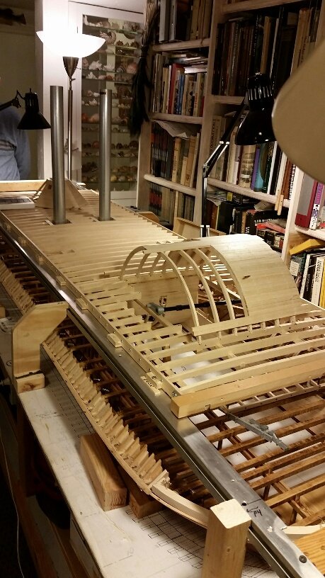
Thanks Antony & Gerhard, Every comment and opinion on this project helps us plan our next step forward. It is indeed a daunting task and we have accumulated so much information over the past 3 years that we are having trouble finding the time for organizing it in a logical sequence for posting. As I mentioned before we currently have a team of 9 Shipcrafters involved in various aspects of the planning, research, material procurement and actual construction of this model. One member is making TurboCad drawings of any details which require machining or casting whenever existing data is incomplete or incorrect and we are continually updating our "Research Outline" which I posted earlier and which describes any problems we have uncovered with existing data. We willingly share all this information with individual modelers but are not at present planning any total drawing package. Unfortunately, our focus has to be on completion of the model. The attached photos show 8 of 9 participants and the model as of mid-April which we hope to complete next year.. johnhoward

-
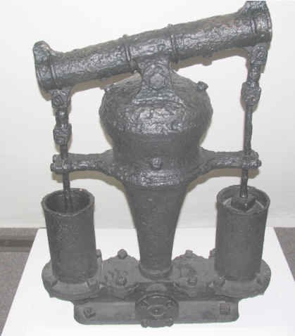
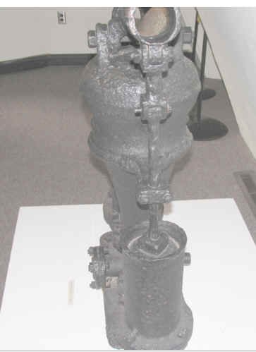
Gerhard, Thanks for your thoughts. I don't think this particular pump was ever driven by the "Doctor" or any other steam engine. It appears to simply be a manually powered bilge pump and function similarly to an "Elm Tree" pump or some of those unpowered "wobble type" bilge pumps on small boats today. The "Doctor" auxiliary steam engine had 4 pumps of its own which were designed to directly intake dirty river water. To serve as a bilge pump all they had to do was switch the "Doctor" input from river water to the water in the bilges. The multi-function "Doctor" provided this dirty water to the boilers, to dampen the firebox or as a firehose in an emergency. I guess it would even provide this bilge water to the boilers "mud" drums which would just clean it up a little before turning it into steam.This wouldn't be considered to be "good engineering design practice" but it worked. In any case, these ironclads had plenty of extra manpower available, except during combat. johnhoward
-
Research for "City Class" Ironclad bilge pump configurations for our model of the ironclad "USS St. Louis". Attached are several photographs taken by Bob Hill during a visit several years ago to the National Parks Service "USS Cairo" Museum at Vicksburg, Mississippi which appear to show a manually operated bilge pump possibly recovered with the Cairo in 1963, however Bob couldn't remember their exact context. So far, I haven't been able to find any corroborating detailed data or drawings showing this or any other unique bilge pump configuration or its possible location on these ironclads which undoubtedly had a chronic leakage and "hogging" problem. In her study on, "Artifacts of a Gun Boat", Elizabeth Joiner reported that the bilge pumps on the USS Cairo were made from hollow logs and one 7.7-foot length with a 5" diameter core hole was actually recovered and this agrees with practices on most wooden sailing ships of the pre-Civil War period. The "Doctor" auxiliary steam engine also served in the bilge pump capacity when necessary and was mounted just aft of the boilers for its primary role. One possibility is that the "bilge pump" on display at the museum was another auxiliary device and its most logical usage appears to be to pump bilge water out of the "hogged" stern booms adjacent to the paddle-wheel. We therefore are building a bilge pump model, sized for manual operation and hope to uncover evidence permitting its inclusion on our model of the USS St. Louis. (sister ship of the USS Cairo) Any additional information or comments would be welcomed. johnhoward St. Louis Gateway Model Shipcrafters
.jpg.649ed99b00cffbb4c5be23b0e9bb8872.jpg)
.jpg.3d26fcd4656068d04dd693c4dfe11e02.jpg)
.jpg.20ed66d59bd8877559a4d3f258186ba3.jpg)
-
Gerhard, I will be very interested in following the design of your live steam propulsion for your model. Will it have 2 engines? You probably wouldn't need them for the model, but I'm sure you know that the original Cairo had balance "buckets" to offset the eccentricity from the heavy weight of the 2 iron engine input bellcrank arms on the axle which were at 90-degrees to each other causing the wheel to vibrate. This was normally done on stern-wheelers by doubling the thickness of the paddle planks (Buckets) opposite from the bellcranks. However, this wheel, having an odd number of spokes (17) doesn't have any paddle planks exactly opposite the bellcranks so it probably needed 4 spaced double planks to achieve real balance. All the other stern-wheelers I've studied had an even number of buckets but the City Class designers must have had some good reason for 17. Or perhaps, the Cairo wheel was just "borrowed" from a side-wheeler steamboat which only has a single engine bellcrank per wheel and therefore had the wholly different problem of maintaining power thru the end of its engine stroke. johnhoward
-
Gerhard, I knew it wouldn't make any difference to your individual paddlewheel parts as is also the case with ours. For our scale, other than just being more accurate, the ring spacing significantly affects the wheel assembly. Unfortunately, Bob expected higher accuracy from Ashley's 1981 NPS plans, his primary source in making his set. We and many others have done the same for their Cairo drawings and models over the years. We are now very happy to be able to share our research findings in a timely manner with you and any other modelers so that they will at least be aware of them and can decide for themselves. johnhoward
-
Very nice CAD work Gerhard, One comment that might make your paddlewheel assembly easier is that the 4 identical frames were actually all facing the same way with the pocketed side of the hubs on the port side for the spokes. This makes the 3 spaces between the rings identical as well as the cross bracing arrangement, rather than "handed". Some versions of the Cairo drawings show this incorrectly but Vicksburg reassembled their original crumpled wheel correctly as you can probably detect in their photographs. johnhoward
-
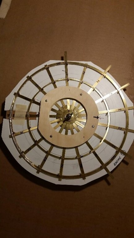
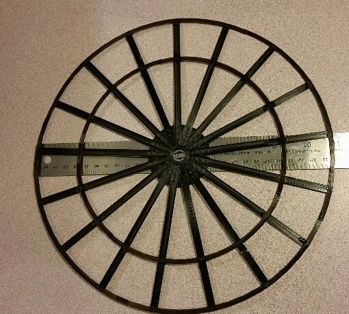
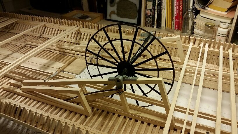
Gerhard, I think you are pretty safe using the Constellation's second cutter drawing sized for 26-feet OAL. I'm amazed at how fast you move from subject to subject on your model. Attached is a photo taken last week of our paddle wheel model in its assembly jig that might be of interest. This is the third of the 4 identical rings we need. It is all brass, consisting of a machined pocketed hub and 2 axle collars, .032" thick sheet brass 6" diameter inner ring, 11" diameter outer ring, and 17 spokes , all riveted together with #18 brass escutcheon pins. We first prototyped this ring assembly, axle and bellcranks using a laser printer as shown in the other photos before committing to brass parts. The tricky part of the paddlewheel will be its final assembly with its "birds nest" of thin rod cross bracing. We are experimenting with the use of continuous fine multi filament brass wire, stretched taut with tin solder wicked into the wire at each ring intersection to secure it in place. We were planning to use an electric motor to demonstrate the paddlewheel in operation however the museum doesn't want any power in their display cabinets. johnhoward
- 293 replies
-
- 12
-

-
Great work Roger on your USS Catskills model and thanks for the ship's boats technical information. The source for USS Cairo's boats is not included in the list of suppliers in the NPS Historical Structural Report so I assume they were provided by the US Navy yards and not built locally by Eads in St. Louis. The Cairo was only under Navy control the short time between October 1862 until December 1862 when it was sunk by a mine so most of its combat action was when under Army management. It may have been refurbished upon switching commands. My team is building the Cairo sister ship, USS St. Louis at 1:24 scale as she appeared just prior to this October 1862 transfer. The only reliable ship's boats information we have found is the distance between the Cairo's boat support davits which were recovered from the Yazoo River in 1963. johnhoward
-
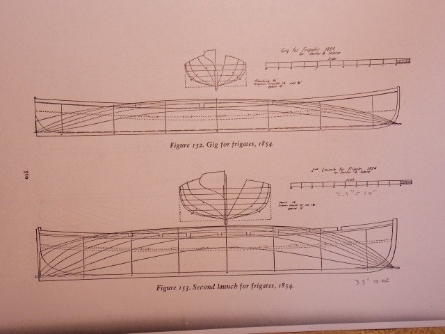
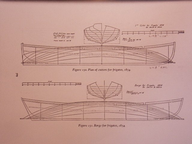
Gerhard, As a follow-up to Gerald's great lead on use of the 1854 USS Constellation cutter and launch drawings for our ironclads, I found the attached drawings in Chapelle's "History of the American Sailing Navy, which provide additional details for their thwarts and oar lock slots in 1854. They also show a higher and narrower sternwale which seems to be borne out in some of the contemporary Civil War photos. Chapelle's book also provides the US Navy table-of-allowances (listings) of various length versions of these ship's boats for their "mother" ships just prior to the ironclad era. If you assume that the USS Cairo drawings correctly depict the davit locations, the cutter length would be about 26-feet to fit between them. The USS Cairo launch stowed at the aft port side set of davits could be a few feet longer (we are using 28-feet) to account for additional oarsmen. I believe the launch was used for more official and ceremonial purposes while the cutters served as the work horses. A broader sternwale would most likely be required for transportation of the 12-pdr boat howitzer carriage. It is also possible that the USS Cairo carried more than one version of their cutters. Knowing the military system, I think we will eventually be able to find comparable ship's boats information directly for the ironclads. johnhoward
-
Thanks Gerhard, We have a plethora of additional issues, notes and back-up data on this subject that we haven't yet assembled into readable format but I will concentrate on those for the exterior view of the ironclad which are probably most important to modelmakers. johnhoward
-
Gerhard, Yes, the HSR does refer to steam powered pumps in addition to the steam powered capstan but we're not sure this meant the the same "auxiliary engine". The "doctor" engine was a multi-purpose device and included several pumps and functions including use as a firehose. It could easily have been switched to use as a bilge pump whenever required. Other small leaver operated manual bilge pumps were recovered with the USS Cairo. Nice work on your 12-pdr carriage. In response to your comment on ammunition boxes: We don't plan to include ammo boxes to our carriage for ship board use. Most contemporary photos of the lightweight carriage in shipboard use do not include the ammo boxes which would defeat the light weight concept. They would make more sense when the 12-pdr was used on land as an assault weapon. The howitzer ammunition recovered with the Cairo was packaged in a small wooden box with a 3 by 3 layer (9 rounds) already fused an ready to fire. johnhoward
-
Attached is the Revision E(draft) of our Gateway Model Shipcrafters Research Outline which identifies issues with existing data being used to define the Civil War era City Class Ironclads. We are following the results of this research as we scratchbuild our 1:24 scale model of the USS St. Louis for the Missouri Civil War Museum but wanted to start sharing it with with all interested model builders johnhoward Secretary, Gateway Model Shipcrafters St. Louis, Missouri Research Outline for City-Class Ironclad Source Issues (Rev E draft).doc
-
Very nice work Gerhard, We'll be starting ours soon, but of course it will be twice the size at our scale and should be a little easier to make. By the way I've attached another possible version of the capstan steam power system in case you don't like the PTO shaft idea. We originally preferred this idea before we determined it would be in the middle of the coal bin. It does look very similar to the Cairo gearing setup. johnhoward capstan patent(1).bmp Capstan Patent Explanation(2).bmp
-
Gerhard, Attached is a photo of our USS St. Louis ironclad taken a month ago. Unfortunately we found it impractical to manage or maintain the real time log on this forum but we have retained all the data and I am trying to retroactively bring the log up to date. We have 9 of our Gateway Model Shipcrafters participating part time on this project which has been in continuous construction since September 2014 and we expect to take at least another year to complete. As you have independently recognized for your USS Cairo, researching to verify or correct the enormous amount of conflicting or missing data for the City Class Ironclads is a full time job by itself. johnhoward
-
Gerhard, I've attached the information I have accumulated so far on the Cairo's boats, one launch and three cutters. The photos and outline drawings probably would be enough for a reconstruction but we would prefer an existing detailed drawing. I haven't yet selected a particular plan for their construction but I've previously read somewhere, possibly Gene Bodar's log, that they were similar to "Bristol Boats". I haven't searched for this yet but it shouldn't be too hard to find. We plan to display two of them on the starboard side, covered with tarps so only the planform would really be necessary. One of the others on the port side would be open and contain a bow mounted skid for the 12-pdr boat howitzer but not the barrel so details of this could come from those drawings. We are hoping to be able to complete our model in about another year so I still have time for research as the boats will be one of the last things to model. I hope this helps a little, johnhoward Cutter beside-USS Cairo.bmp Cutter section.bmp Cutter,Civil War.bmp Carondelet(2).bmp