
HOLIDAY DONATION DRIVE - SUPPORT MSW - DO YOUR PART TO KEEP THIS GREAT FORUM GOING! (Only 13 donations so far - C'mon guys!)
×


johnhoward
-
Posts
162 -
Joined
-
Last visited
Content Type
Profiles
Forums
Gallery
Events
Everything posted by johnhoward
-
Thanks Gerhard, Good luck with your projects and research. A live steam powered RC ironclad should really be amazing. johnhoward
-
Gerhard & Others, There are several questions in the previous few responses which are very helpful in arriving at the most plausible configuration for the USS Cairo and the other "City Class Ironclads'. We have been researching this for about 3 years while meanwhile constructing our 1:24 scale model for the Missouri Civil War Museum and I agree we still don't have all the answers. All of the existing drawings are based on a mixture of actual recovered fragments of the original ironclad, the original written specifications, and reconstructions of the most probable technically plausible configuration. The building of our large scale model has given us better insight for verifying or determining the most likely reconstruction. Question 1: Are you sure the capstan was steam driven? Answer: The best proof comes from the NPS Historical Structural Report (HSR) for the USS Cairo under the section on "Auxiliary Equipment" which lists; Steam driven capstan, Steam driven pumps, Hand pumps, and Feedwater steam engine ("Doctor"). The recovered capstan does include release pins to permit manual powering and gearing for two speeds(or mechanical advantage). However, I think steam power would prove most useful for dislodging a 500+ ton ironclad from a sandbar or snag in the shallow US Western Rivers. Question 2: ... can we find out the location for this second auxiliary engine? Answer: Since this engine apparently was not recovered, I doubt that we will ever find any absolute proof, however as I outlined in a previous response, our model was used to reconstruct the simplest method of moving the scaled down (Ashley) engine out of the coal bin via a PTO shaft and this is offered for consideration. Question 3: ... so, the Doctor should be built in but turned 90-degrees,...? Answer: Yes, however Gene Bodar actually also located the "Doctor" a little too far aft on top of the paddlewheel feedwater chute which he made flat rather than curving up in front of the wheel. (You may also notice he installed his nicely made boilers backwards) [See: Paddlewheel Inlet attachment] johnhoward
-
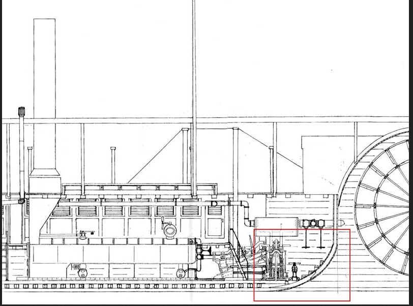
Paddle wheel inlet.bmp Gerhard, The "doctor" engine is a whole different story. Unfortunately the Cairo's "Doctor" although originally found, was later lost in the Yazoo River. The version of the "Doctor" shown on Ashley's plan sheet 27(which I assume you have) is pretty good for making a non-functioning model but appears to be a little fancy for the ironclads. Some version of it was carried in almost every later steamboat for boiler safety. Ashley (and Bob Hill) incorrectly show it mounted lengthwise on the paddlewheel feedwater ramp whereas Meagher's reconstruction correctly shows it mounted athwartship in roughly the same location but forward of the ramp and aft of the boilers, between the main engines. (See: Paddlewheel Section attachment). Ashley's sheet 24 Propulsion System Schematic is also full of errors. A functioning "Doctor" would make an interesting model in itself. Some of the attached text helps explain how the doctor really works. We haven't found any evidence of power assisted steering on the ironclads. Later on some form of hydraulic power rudder assist was implemented on Western river craft. The traditional steering wheel, drum, and chain or cable linking to the tillers seems to have been used, however the tillers were over 100 feet away from the steering wheel so it appears that some system of taking out backlash must have been used. All sternwheeler steamboats would have a similar problem until some of them moved their rudders forward of their paddlewheels closer to the steering wheel. Whatever the case, the lateral control was notoriously ineffective on the ironclads. johnhoward Paddle wheel inlet.bmp
.jpg.68be797ae8bff61e547d8577d67a6a55.jpg)
.jpg.4f80729824b2e9cb294605171d320e1b.jpg)
.jpg.557f0b8c48882c6a50db701aff2dcdd0.jpg)
.jpg.a1a8c962e6019815b5213db6e9a557b6.jpg)
.jpg.51ae546bb947ba705ed0b3ab00c9b579.jpg)
-
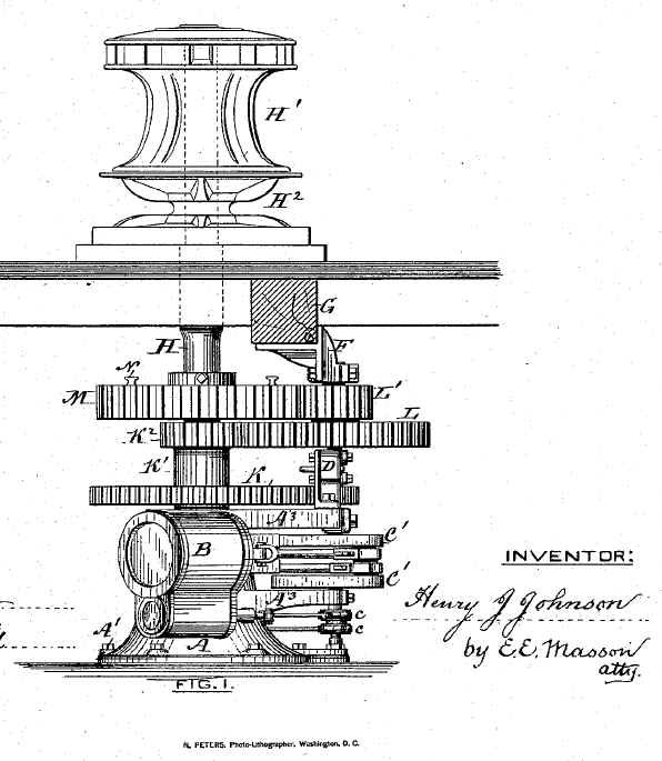
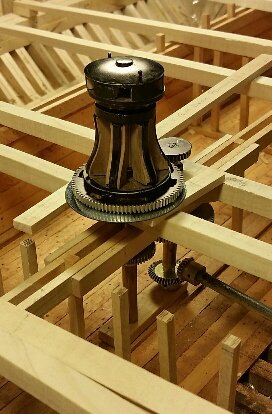
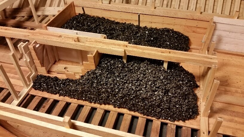
Gerhard, We have not been able to find any direct evidence of an auxiliary steam engine being recovered with the USS Cairo but the version shone in Ashley's (Bob Hill's source) 1981 NPS drawing depicts a similar engine he apparently found in the US National Archives and a sketch showing it in the lower casement of the hull (perhaps this is where something was recovered in 1963). However the engine in this sketch would be far to large for capstan power as it is even larger than the engines powering the paddle wheel. We have found several drawings of mid-1800 steam powered capstans which were provided with US Patent applications which provide a more reasonable scale for this engine which would be more integral with the capstan. However, the capstan for the USS Cairo is located directly above the centerline coal bin between the Commissary Stores Room and the Fire Room so the gearing and Auxiliary Steam Engine would most likely have been powered by a remote engine and PTO shaft similar to that shown on the 1981 NPS drawing. Our reconstruction solution therefore was to install a smaller version of the 1981 NPS drawing Auxiliary Engine in the port side lower casement with its PTO shaft leading to the centerline capstan instead of having an engine in the middle of a coal bin. We have installed a box around the below deck bevel & spur gearing to isolate it from the coal. So far we have only mocked up the auxiliary engine but it will simply be a reduced scale version of Ashley drawing. I've attached a few photos which I hope will make this description clear. johnhoward capstan patent(1).bmp Capstan-Cairo.bmp
-
Gerhard, We live in Missouri which is not, too far from Vicksburg, Mississippi and had been planning a trip there to check out other technical details. We were coordinating with the Cairo Museum curator, Elizabeth Joiner, for assistance getting better access to remains than the pure tourists can get. (They need to protect the Cairo remaining fabric from souvenir hunters) However, Mrs. Joiner is no longer the curator and a replacement or technical contact hasn't been identified so any trip has been delayed indefinitely. Bob Hill and 10 members of the Tampa Bay Ship Modelers visited Vicksburg a few years ago and took a lot of photos which were very helpful but I don't recall any of the mural. One other factor which leads us to favor the lighter carriage is that the original armament originally allocated to these ironclads while under US Army control was a "mixed bag"of the discarded and obsolete ordnance that nobody really wanted. Inter-service rivalry was alive and well. The Cairo was technically under the command of Gen. George McClellan who was stationed nearly 1000 miles away in Virginia and probably never even cared about its operation. The Navy field carriage usually included ammo boxes and would be more practical for a land assault by Marines which are part of the US Navy. The lightweight carriage could be easily broken down for storage aboard ship where space is at a premium and would be easier to handle on the cambered Hurricane deck. I suspect that the carriage recovered with the Cairo was actually still in its crate I can imagine that both carriage versions were in use on some of the seven "City Class" ironclads and we don't really have any specific information on which was on our "USS St. Louis", but the lighter version looks more interesting. johnhoward
-
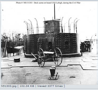
Gehrhard, You may want to consider these photos before committing to a field carriage for your 12 pdr. Early in the Civil War the lightweight version like these were used on ships primarily to minimize handling weight. Later they decided the weight savings wasn't so important. We also concluded that it is a 12-pdr lightweight in the Cairo mural photo but couldn't detect much of a wheel rim. By the way, the hurricane deck camber is pretty obvious in the bow casement. johnhoward
-
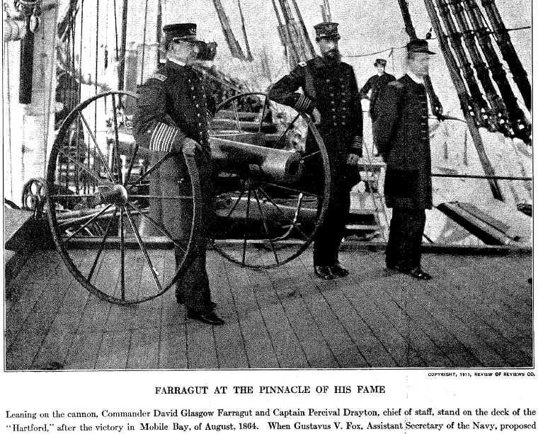
Gerhard, This is a pretty good photo of the light 12 pdr except the wheels are the heavier field version. The attached (carriage only) photo has the correct lightweight wheels. "12 Pdr Boat Howitzer Carriage Model(1).bmp. johnhoward 12 pdr Boat Howitzer(2).bmp12 pdr Boat Howitzer(2).bmp 12 pdr Boat Howitzer Carriage Model(1).bmp
.thumb.jpg.fde9afc1b12d179dc46744f4944b11fe.jpg)
-
Regarding the previous Wikipedia comment on "the 12 pounder rifle" for the USS Cairo; each of the City Class Ironclads were allocated one lightweight version of the 12 pounder boat howitzer (not rifled) & a portable wrought iron carriage while commanded by the US Army. (until October 1862) . These were the supposedly removed when the US Navy took command, however the carriage and a box of fused 12 pdr ball howitzer shells was reportedly recovered with the USS Cairo in 1963 while the barrel supposedly had been removed during a stop over in Cincinnati, Ohio just prior to its sinking in December 1862. These howitzers had two potential functions on ironclads: one was to repel possible enemy boarders and the other was to be either transported or mounted in the bow of the cutter for offensive or defensive action. We haven't found any record of the howitzer ever being used in action. A version of this howitzer is on display at the USS Cairo Museum in Vicksburg. We plan to mount a model of this howitzer on the Hurricane deck of our 1:24 scale version of the "USS Cairo" sister ship, "USS St. Louis" in its "boarder repel mode" just prior to its renaming to "USS Baron DeKalb" and transfer to the US Navy in October 1862. johnhoward
-
Bob Hill did a very nice job of vectorizing and combining separate sheets of the original 1981 NPS drawings by Ashley to make them more usable for model makers. The biggest problem is that Ashleys drawings contained many errors, omissions and inconsistencies which Bob didn't attempt to correct. For a 1:50 scale exterior shape model, other than the lack of deck and deckhouse roof camber which is obvious from the contemporary Civil War era photos, most of these can probably be ignored. However, if you plan to include things such as accurate cannon and their carriages, the unusual 17 spoke paddlewheel, ventilation funnels, rudder & tiller configurations, and other internal features such as for our model, you probably will find our discoveries interesting. This is "a work in progress but I will attempt to include a preliminary version of this research report in our "Scratch Build Log for the ironclad USS St. Louis" on this forum. Johnhoward
-
Hi Gerhard, The Vicksburg PDF drawings (VICK-306-120514) represent the surviving portions of the USS Cairo as currently displayed today at the Vicksburg National Park and are therefore most useful fur the metal items such as the correct 17 spoke paddlewheel and rudder tillers but they do also help correctly locate the missing elements. These drawings were apparently released in 2015 for their 150-year Civil War anniversary and used to be posted on the main Vicksburg National Park and USS Cairo Museum web site. I just accessed this site but was unable to quickly find the drawings. I will keep searching and will advise if I find the current site. One of our Shipcrafter members started the scratch build log for our "USS St. Louis" model on this forum 2 years ago which identified some of the drawing issues we were uncovering, however it quickly became unmanageable since we have about 9 participant Shipcrafters working in parallel. Perhaps I can get him to summarize the errors we have identified so far via the USS St. Louis log. Johnhoward
-
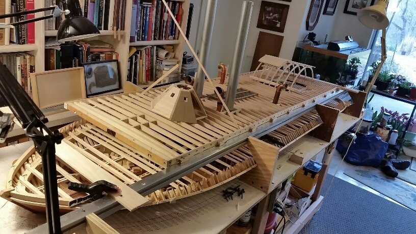
We, the St. Louis Gateway Model Shipcrafters are currently scratch building a 1:24 scale plank-on-frame model of the USS Cairo's City Class, sister ship USS St. Louis for the Missouri Civil War Museum (MCWM). We started this project in September 2014 using the Vicksburg 1981, 28 sheet set of plans by Ashley and their Historic Structural Report(HSR) which seemed to be the standard source for the modeling community at that time and appeared to cover everything we needed to build an authentic model worthy of display at the MCWM. The attached photo represents our progress as of March 2017. The starboard side of this 7.5-foot long model will represent the ironclad's finished exterior while the port side will have substantial openings to reveal substructure and internal equipment. Unfortunately, we immediately began to detect obvious errors in these plans such as a lack of deck camber and deck house roof camber which would be particularly noticeable at our large scale. Correspondence with NPS Vicksburg led us to NPS Denver, who actually managed the USS Cairo reconstruction project, confirmed these errors and our fears that others probably existed partly because of the poor condition of the USS Cairo's remains in 1981. We therefore began our own concurrent intensive research activity to verify everything we could before we fabricated it. This included referring to an earlier 1968 NPS Philadelphia survey drawing of the USS Cairo hull and a later 2005 Vicksburg subcontractor reconstruction of the gun carriages which were very useful. We also found drafting errors and inconsistencies in Ashley's 1981 drawings, some of which have been superseded by Vicksburg 2015 PDF drawings. Some other sets of plans, such as those by Meagher and Geoghegan(1970), appear to contain reconstructions which make sense. Unfortunately other plans such as Bob Hill's simply relied solely on the accuracy of Ashley's drawings or introduced figments of their own imagination such as C. A. Raven's NRG Journal Article(Summer 2012) which is counterproductive. All existing plans appear to be flawed and the many USS Cairo models currently on public display reflect these errors. Obviously some of the issues we are discovering would not necessarily apply to smaller scale or less detailed models. We are compiling a list of our findings and intend to submit it to the NRG Journal for use as a cautionary "heads up" to future City Class model makers.
- 293 replies
-
- 17
-

-
Other than naming our Scratch Build Log, where can we find instructions on how to correctly set up and post updates? We are building the Ironclad USS St Louis as a club project and have assigned one member as a coordinator but eventually will have about a dozen modelers contributing to the project. Most of our postings will consist of photos and documents reporting individual or team progress. None of us has any experience with posting build logs. Our initial attempt doesn't appear to be correct. Is it possible for more than one member to contribute their portion of the postings or do they all have to originate from a single source? Our attempted second posting update appears as a comment from TomG667 although it actually came from our coordinator. Please help straighten us out. Johnhoward
-
We are trying to start a wood, 1:24 POF scratch build log for the Civil War Ironclad, "USS St. Louis" as a Gateway Model Shipcrafter's Guild Project which will be managed by one of our members here in St. Louis. Are there any special instructions related to setting up this type of log?
.jpg.96f114f2890b015ac964234a088e0040.jpg)