
MORE HANDBOOKS ARE ON THEIR WAY! We will let you know when they get here.
×


JSGerson
-
Posts
2,588 -
Joined
-
Last visited
Reputation Activity
-

 JSGerson got a reaction from kmart in USS Constitution by JSGerson - Model Shipways Kit No. MS2040
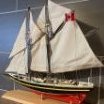
The second canopy frame is completed in one month, half the time it took me for the first one. This is one of the pairs of hatchways at the ship’s wheel. The other one is closed and therefore has no frame. The last two are on the main hatchway. They are a bit smaller and have only seven stanchions each.
Jon
-
 JSGerson got a reaction from Geoff Matson in USS Constitution by JSGerson - Model Shipways Kit No. MS2040
The second canopy frame is completed in one month, half the time it took me for the first one. This is one of the pairs of hatchways at the ship’s wheel. The other one is closed and therefore has no frame. The last two are on the main hatchway. They are a bit smaller and have only seven stanchions each.
Jon
-
 JSGerson got a reaction from Mr Whippy in USS Constitution by JSGerson - Model Shipways Kit No. MS2040
The second canopy frame is completed in one month, half the time it took me for the first one. This is one of the pairs of hatchways at the ship’s wheel. The other one is closed and therefore has no frame. The last two are on the main hatchway. They are a bit smaller and have only seven stanchions each.
Jon
-

 JSGerson got a reaction from Der Alte Rentner in USS Constitution by JSGerson - Model Shipways Kit No. MS2040
A 3/32” hole was drill into each of the two bending jigs to position the canopy hub. The canopy supports were easily bent which created a brass “spider.” Note, the 7th support remains to be fabricated.
-
 JSGerson got a reaction from Unegawahya in USS Constitution by JSGerson - Model Shipways Kit No. MS2040
The assembly was cut off from the working “handle,” the ornamental top was trimmed, and the ornamental brass bead was glued to the bottom stem. The second photo shows assembly lying on the hatchway.
-
JSGerson got a reaction from Unegawahya in USS Constitution by JSGerson - Model Shipways Kit No. MS2040
To complete the mechanical hub structure, a locking ring was cut from the 1/8ӯ tube and fitted over the slots converting the slots into holes and locking the supports to the hub.
-
JSGerson got a reaction from Unegawahya in USS Constitution by JSGerson - Model Shipways Kit No. MS2040
A length of 2 3/8” 0.020” brass rod was cut and bent so that one leg was 1” and the other 1 3/8” for the two supports lengths of the frames. This is a bit more than was needed, but it is easier to cut off excess than extend a short leg. Three pairs or 6 supports were created, however, this canopy required 7 supports. The last support (non-pair) was planned to be added once the canopy was assembled. At that point the seventh support will slide into the remaining opening in the hub and be glued into place. A length of 1/16”Ø brass tube was inserted into the hub assembly as a “working” handle. As each pair of supports was added to the hub, it was secured by CA glue.
-
JSGerson got a reaction from Unegawahya in USS Constitution by JSGerson - Model Shipways Kit No. MS2040
The end of the 1/8” tube was sawed off, producing a 1/8”Ø “crown” shaped component. Next, a slice of 3/32” tube was cut creating the seat ring, which was inserted into the bottom of the “crown.” Inside of that, a length of 1/16” tube was inserted creating the inner wall and axial of the hub assembly. Following the plan, additional pieces were added to create the hub.
-
JSGerson got a reaction from Unegawahya in USS Constitution by JSGerson - Model Shipways Kit No. MS2040
The trick here is cutting the brass slots to accept 0.020” Ø brass rod. My fine-tooth miter hand saw is 1/128” (0.008”) thick, cutting very narrow slots. The slots were 1/64” too narrow and my files were too thick to fit in the cut slots to widen them. Using various drill bits in my variable speed Dremel at the slowest setting, the slots were widened by sliding the spinning drill bit up and down the slot cutting with the bit’s side. Sorry, I could take a picture of this, as I needed both hands to perform this procedure.
-
JSGerson got a reaction from Unegawahya in USS Constitution by JSGerson - Model Shipways Kit No. MS2040
Fifth Attempt
Ok, let’s be more pragmatic and increase the diameter of the hub to 1/8”Ø and sacrifice a bit of scale. If I’m going to do that, I can also discard the styrene for the hub material and come full circle and use brass tube once again. Since I won’t be drilling holes, (the reason for the plastic in the first place), but cutting slots, I’ve eliminated the brass holes problem.
-
JSGerson got a reaction from Unegawahya in USS Constitution by JSGerson - Model Shipways Kit No. MS2040
Fourth Attempt
The next development was the idea to make a double support such that the brass rod would pass into the hub and back out through a difference opening as a second support. This would mechanically fasten the brass rod to the hub. To do this, I would have to change the drilled holes in the hub to vertical slots so the brass rod could be dropped into the openings. It’s not like the rod can act like a piece of string that can be threaded.
This introduced a new problem. Once the holes in the styrene hub were converted to vertical slots, the remaining vertical styrene material was now narrow, flexible, and weak and would break off should anything tug on them…like the brass canopy rods. Additionally, more room is needed to accommodate the bends.
-
JSGerson got a reaction from Unegawahya in USS Constitution by JSGerson - Model Shipways Kit No. MS2040
Third Attempt
My next idea would be to cut the 1/16” Ø brass tube leaving the 1/32” Ø rod alone uncut. Now there would be two 1/16” Ø brass tubes one on top of the other with a gap in between, wide enough to accept the 0.20” brass rods. This expose tube wall would extend the rail seat another 1/64”. Mechanically, it is slightly stronger than the previous idea, but still fragile. And how does one assemble 7 to 8 spokes into the hub and hold them in place precisely to glue them together with sufficient strength?
-
JSGerson got a reaction from Unegawahya in USS Constitution by JSGerson - Model Shipways Kit No. MS2040
Second Attempt
I was forced to make a small dimensional compromise. The top part of the full-scale ornament is 2” in diameter which scales down to 0.03” (1/32”). This had to be enlarged to 1/16”Ø due to fabrication practicality.
At the center of the hub, is the ornament which consists of a 1/32” brass rod which is inserted through a 1/16” brass tube. At the bottom of the tube, the 1/32” rod extends out into the 1/16” brass bead. At the opposite end, the rod and tube were to be filed into a rounded point.
However, the enlargement forced me to remake the styrene hub component. The 3/32” Ø styrene tube’s inner diameter was about 1/64” was too narrow to allow the 1/16” Ø brass tube to pass through. It had to be drilled out with a 1/16” drill bit. This left a very shallow 1/64” tube wall rail seat for the 0.020” brass rod to rest on and glueing surface. Mechanically, this would be very fragile and would not secure the 0.020” brass rods.
-
JSGerson got a reaction from Unegawahya in USS Constitution by JSGerson - Model Shipways Kit No. MS2040
First Attempt – Original Plan
As mentioned in my earlier posts, I had to forgo using a brass hub because I had difficulty drilling holes in brass and thus substituted styrene. The styrene hub 8 circumferential support positions, of which 7 of them for this canopy support, were drilled with a hole to accept an arched support. Unfortunately, drilling these holes practically cut the styrene tube in half.
-
JSGerson got a reaction from Unegawahya in USS Constitution by JSGerson - Model Shipways Kit No. MS2040
To fabricate the arched framework, I had to work out how to make the central ornament. If I had a metal lathe (and knew how to use it) it might have been relatively simple...I think, maybe. But I don’t, so this is how, why, and what I worked out, based on the US Navy plans.
-
JSGerson got a reaction from Unegawahya in USS Constitution by JSGerson - Model Shipways Kit No. MS2040
The second canopy frame is completed in one month, half the time it took me for the first one. This is one of the pairs of hatchways at the ship’s wheel. The other one is closed and therefore has no frame. The last two are on the main hatchway. They are a bit smaller and have only seven stanchions each.
Jon
-
 JSGerson got a reaction from mort stoll in USS Constitution by mtbediz - 1:76
Nice, clean, and precise...your usual excellence!
Jon
-

 JSGerson got a reaction from mtbediz in USS Constitution by mtbediz - 1:76
Nice, clean, and precise...your usual excellence!
Jon
-
 JSGerson got a reaction from Stevenleehills in USS Constitution by JSGerson - Model Shipways Kit No. MS2040
The second canopy frame is completed in one month, half the time it took me for the first one. This is one of the pairs of hatchways at the ship’s wheel. The other one is closed and therefore has no frame. The last two are on the main hatchway. They are a bit smaller and have only seven stanchions each.
Jon
-
 JSGerson got a reaction from PaddyO in USS Constitution by JSGerson - Model Shipways Kit No. MS2040
The second canopy frame is completed in one month, half the time it took me for the first one. This is one of the pairs of hatchways at the ship’s wheel. The other one is closed and therefore has no frame. The last two are on the main hatchway. They are a bit smaller and have only seven stanchions each.
Jon
-
JSGerson got a reaction from mtbediz in USS Constitution by JSGerson - Model Shipways Kit No. MS2040
The second canopy frame is completed in one month, half the time it took me for the first one. This is one of the pairs of hatchways at the ship’s wheel. The other one is closed and therefore has no frame. The last two are on the main hatchway. They are a bit smaller and have only seven stanchions each.
Jon
-
 JSGerson got a reaction from GGibson in USS Constitution by JSGerson - Model Shipways Kit No. MS2040
The second canopy frame is completed in one month, half the time it took me for the first one. This is one of the pairs of hatchways at the ship’s wheel. The other one is closed and therefore has no frame. The last two are on the main hatchway. They are a bit smaller and have only seven stanchions each.
Jon
-
JSGerson got a reaction from mtbediz in USS Constitution by mtbediz - 1:76
I would love to have the dividing attachment, but for the cost and the amount of times I could use it in the future, I can't justify the cost. That and the fact my Dremel drill stand is not what you would call a precision instrument. Setting up the X-Y table on the drill stand is a pain because it's held in place with clamps and alignment is done by eyeball and trial and error.
As for the draw plate, I got mine from Byrnes Machine Tools and it was worth every penny. I bought it because the drawplate had from Micro-Mark just wasn't a precision tool especially for the fine holes. I've learned not to buy tools before I need them, because invariably, I didn't need them. The other side of the coin is not having the tool when you need it and it's too late to buy it, like the dividing tool.
I wish you well on you new acquisitions.
Jon
-
JSGerson got a reaction from GGibson in USS Constitution by Der Alte Rentner - Model Shipways - 1/76
I know you asked this question to Geoff, but I thought I would throw in my two cents. I've always felt that the eye bolts supplied by Model Shipway were for the most part, too big for the scale of the model. Some years ago I found on eBay, Model Shipway supplied 1/32" brass eyebolts sold in a 1,000 items per bag. A 1/32" eyebolt is about 2.4" scale (1:76.8). I have used just about every one of them. Unfortunately, I could not find that deal again. But I have found from various vendors the 1/32" eyebolts both in brass and copper but sold in smaller units. For me, they are a must have item. I suggest that you have a supply of these as they will be very handy to have.
Jon
-
JSGerson got a reaction from mtbediz in USS Constitution by mtbediz - 1:76
I really wanted the canopy to have the center ornament that others had made. I committed myself and I will finish them before the decade is done🙃!
Jon