JohnE
-
Posts
309 -
Joined
-
Last visited
Content Type
Profiles
Forums
Gallery
Events
Everything posted by JohnE
-

Frégate d'18 par Sané , la Cornélie
JohnE replied to JohnE's topic in CAD and 3D Modelling/Drafting Plans with Software
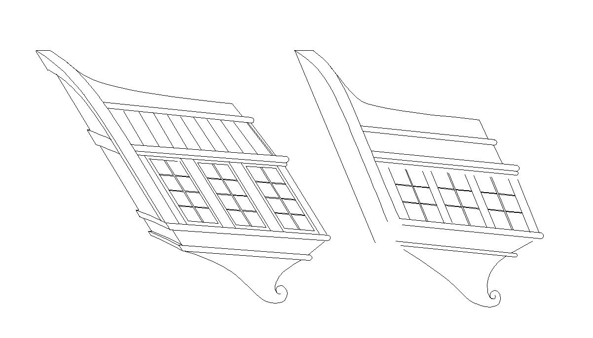
Figurehead was a representation of Vesta (Hestia), the goddess of home, hearth, chastity, and familial virtue, hair braided into a wreath, in Roman fashion, left arm cocked up and her hand holding the “vessel of sacred fire”. Not determinable, vessel could have been a cup, or a cone-shaped torch made of elm rods, both are iconographically valid. Fanciful carving motifs were elm (one of Vesta’s symbols) and believe it or not, the lilly. The notes say fleur de lis, but whether the classic symbol or another, more graphically correct, is unknown. I tend to opt for the second, since the iconography is of the Virgin Mary, that took on many of Vesta’s virtues and whose symbol is the lilliy. Bad enough that one puts references to the Virgin on a Revolutionary ship, without casting her symbols as artifacts of the Ancien Régime. The stern carving is very briefly described. Cornelia seated, her left arm extended to embrace the children, her right arm held out in negation of the crown [of Ptolemy]. The children would have been Tiberius and Gaius Graccus. The children’s description is not noted – cherubs with symbols of the tribunate? Actual ages? With symbols? Nothing as to who/what is offering Ptolemy’s crown. Presumably it’s some guy, so as to balance the carving density of the children on the other side. Anyhoo, that’s what’s there. Problem is, I can’t draw worth crap; can draft, just can’t draw. On my best day, it might be good enough for South Park, so you know what I mean. Looking for someone who can implement these images. They will get full recognition. Otherwise, what ya see is gonna have to be what ya get. John -
Frégate d'18 par Sané , la Cornélie
JohnE replied to JohnE's topic in CAD and 3D Modelling/Drafting Plans with Software
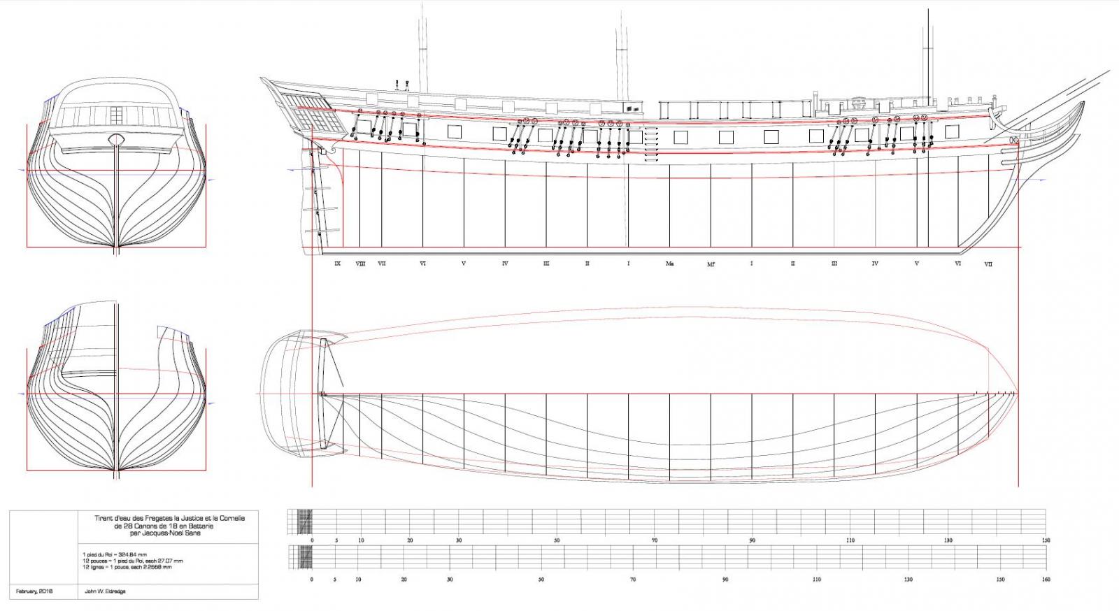
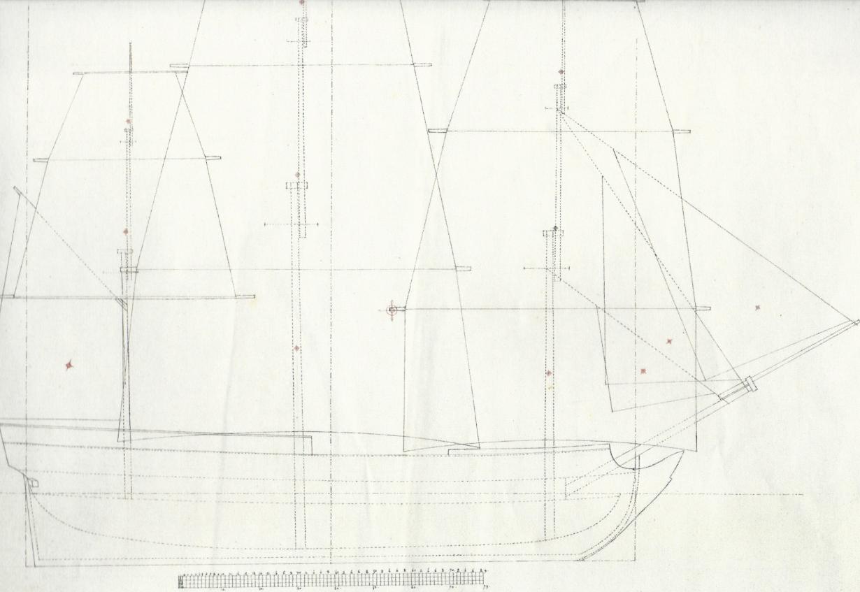
Okey dokey, then. The pretty profile plans are finished and scales added. Top is French pieds du Roi, bottom is English feet. Fairly sure I got the scaling right so that pouces and inches scale as well. I still have marking, labeling, and annotations, to do on the "techie" version, with all the reference lines, buttock detail, and bears, oh my, but that's fiddly bits. Then I have to figure out how to save it in a properly scaled pdf file so people can use it. I wouldn't mind some input, though. I'm looking at 1:48 scale. My drawing space is 1:12, so I have lots of room to maneuver. Final, published, scale recommendations will be heartily appreciated. Also, suggestions as to additions to the basic lines plans are welcome. I'm used to doing 30-60 foot offshore racing sailboats. This is my first attempt at something of this scale and genre and need all the help I can get. Thanks. John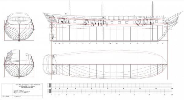
-
Frégate d'18 par Sané , la Cornélie
JohnE replied to JohnE's topic in CAD and 3D Modelling/Drafting Plans with Software
Thanks all for the likes and comments. Too true, Druxey, too true. I'm learning much from this project. Made a mistake and put an earlier drawing in the last post. Substituted the correct one. Here's what the second plan set will include. Still have to do the stern elevation on the body plan for this, as well as the deck outlines on the half-breadth, but that should be just fiddly bits. Have all the reference lines and offsets done, just need to do the curves. Then do the three scales; French, British, and Metric and ... finis. Whew !!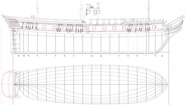
-
Frégate d'18 par Sané , la Cornélie
JohnE replied to JohnE's topic in CAD and 3D Modelling/Drafting Plans with Software
Okey dokey then, enough with fiddling. Slicked up the lines between the half-breadth and profile plans. Worked out the deck lines and put in Sané's DWLs. Looking very good. Will have to do multiple pages because of all the different stuff that has to be captured, Have a plan page with 2 body plans, including all the tech stuff, and a profile and half-breadth showing the tech stuff. Will have another plan page that shows the "pretty" profile and has the stern erection on the half-breadth and also on body plan. I am very close to having an acceptable set of plans. I must thank uss frolick for one of his comments somewhere, that brought me up very short and made much of this stuff possible. I have been working with a ton of references and as you can imagine, they are quite inconsistent and they confuse me. But uss frolick said in one of his excellent posts, "if you start with x, you should continue with x". So everything has been normalized to the Rochefort draught of La Justice//Corné'lie. Thank you uss frolick.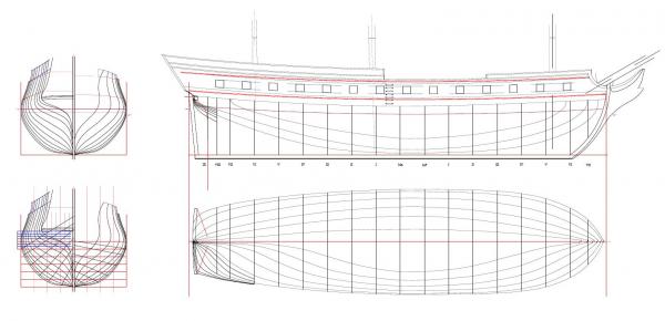
-
Seeking information on determining load waterline
JohnE replied to trippwj's topic in Nautical/Naval History
My personal opinion is that load lines are not all that important in an objective sense, but rather serve as a designer’s reference points. Four Spanish third-rate sister-ships built between 1785 and 1789; two at Ferrol, two at Cartagena. San Ildefonso: Empty – not known. Best Trim – 24’ 3” aft, 22’ 8” forward. San Francisco de Paula: Empty – 19’ 5” aft, 14’ 0” forward. Best Trim – 24’ 8.5” aft, 22’ 9.5” forward. San Telmo: Empty – 19’ 2” aft, 13’ 5” forward. Best Trim – 24’ 4” aft, 22’ 10” forward. Europa: Empty – 18’ 10” aft, 14’ 3” forward. Best Trim – not known. [Francisco Fernández-González] Capitain de Vaisseau Pigue Villemaurin recorded trials of Cornelie: Lightship – not known, Best Trim – 17’ 3” aft, 15’ 4.5” forward. Sill height recorded at best trim – 6’ 5.5”, after six recorded runs at different trim lines. [personal copy, Devis de la fregate de Republique, la Cornelie]. Inferring that the actual load line was a dynamic, after-the-fact, quantity. According to Boudriot, when French 74s were disarmed for yard work, “everything” was removed except the ballast, lower masts and bowsprit. “In the disarmed condition, a 74 would float 8 pieds above water amidships (water to port sill distance) as opposed to the loaded condition where the gundeck sills were 5 pieds above the waterline”. Again inferring that the nominal load line depended on the desired height of the gunports. It was a dynamic, after-the-fact, quantity. In my humble opinion. John -
Seeking information on determining load waterline
JohnE replied to trippwj's topic in Nautical/Naval History
The 1740-1790 period was very interesting because this is when certain “modern” scientific principles took hold. Once again, the period texts give no rule, regulation, instruction, for a consistent, determinable, placement of the “load waterline”. Once again, I believe this is a significant omission. The period extends from Pierre Morineau to Vial du Clairbois and includes Spain’s Romero Landa. Interestingly, at various times during the period, Spain was leading-edge in certain aspects of Naval Architecture and ship design. Morineau followed the earlier paradigm and often put the load line coincident with height of breadth for his corvettes. In fregate and vaisseau designs, the ligne en charge was set at his “height of sill” definitions and the height of breadth fell where it may. Actually, it was the other way around, but “chicken or egg”. Ligne en charge “shall be no lower than a twelfth part (pouce par pied) of breadth below ligne du fort”. So again, LwL was subjective and depended on designer’s choice of section curvature. But LwL was not determinative. The Spanish system, as late as 1790 (and maybe longer), was to use well known principles for buoyancy to do their designs. They launched the ship and made careful records of her “lightship” draught, fore and aft. They loaded her out (with moveable ballast) and made iterative sea trials to determine her best sailing trim. They made careful recordings of draft fore and aft under “best” conditions, and poof, a Load-Waterline. Romero Landa, Reglamento de Maderas Necesarias para la Fábrica de los Baxeles del Rey, Madrid, 1784 [Prof. Francisco Fernández-González, Escuela Técnica Superior de Ingenieros Navales, Madrid] Even today, Lwl is a dynamic quantity. Every racing sailor knows that some boats like to go “butt-up” and some like “butt down”, and it all depends on aspect to the breeze. I would only ever give something a design “lightship” float mark for any of my designs, because the practical reality is so completely different. John -
Seeking information on determining load waterline
JohnE replied to trippwj's topic in Nautical/Naval History
There’s a lot of contextual stuff involved in this. Thought I might start with some thoughts on the 1690s and then post on the 1750s and beyond. I believe Jean Boudriot has slogged through the same stuff (and much more) and come the same conclusions; that this was inferential, subjective, and highly dependent on the coup d’oeil and skill of the designer. Beginning with the 1680-90 period, There were “instructions” issued that set out rules, many of which had already been in use for some time. These “regulations” were cast as His Majesty’s desires, but one assumes they were articulated by the staff of Monsieurs Colbert, through Choiseul. The text includes the following: “Two-decked frigates shall have as their greatest breadth outside plank (dehors des bordages) and at the midship bend (le maître), no more than a quarter of the length. … The depth of hold of the vessel shall be fixed at one half the breadth at the midship bend (le maître), counting from the keel to the “fix” point of the “span” of the gundeck (ligne du 1er pont), in a straight line. … With regard to the height of breadth, or breadth extreme (ligne du fort), His Majesty desires that it shall be precisely observed henceforth to place the height of breadth directly at the waterline (ligne de flottaison en charge).” In 1680-90, French ships were built to a box rule of proportionality. Gundeck position was determined by the proportional mathematics of the rule. But the relative height of gundeck above ligne en charge and/or ligne du fort was determined by a “designer’s rule” as to how far off the water the guns were to be carried. Sill height above deck was given by the “regulation” so one simply moved straight down, from ligne du 1er pont, the requisite amount, and drew a horizontal line which became the reference for the load line (or line of max breadth). They had a subjective appreciation of the problem, and the solution was practical, determinable and repeatable geometrically, although not particularly scientific. It was up to the designers to draw midship sections that would accommodate gundeck heights (from depth of hold values) and give a “ligne du fort” that accommodated a desired height of sill. Given the extent of French proportionality and dimensionality rules for virtually everything else, I find the lack of anything related to waterline placement to be very significant. It infers that there was no generally accepted rule. His Majesty “desired” that the load and max breadth lines coincide, but this made no reference to different hull shapes. Clearly, geometric design wasn’t able to comport with reality at the extremes, so launching a vessel would very often result in either a loud “Bien” or a more subdued “Merde”. Just my humble opinions. John -
Seeking information on determining load waterline
JohnE replied to trippwj's topic in Nautical/Naval History
Hi Wayne. Are you still looking at how les anciens put their load lines? I've been slogging through some French stuff from 1690 to 1790 and have some bits of something-or-other on "ligne d'eau en charge" and/or "ligne de flottaison". 1690 reference is an "instruction" for double banked ship-frigates and fregates legere. 1790 reference is Vial du Clairbois. In between is Pierre Morineau. Didn't want to blundger your thread if you have moved on from this. [ed] btw, this is tehcnically only for French practice on frigate-type vessels, although much of the practical "sense" is applicable elsewhere. John -
Frégate d'18 par Sané , la Cornélie
JohnE replied to JohnE's topic in CAD and 3D Modelling/Drafting Plans with Software
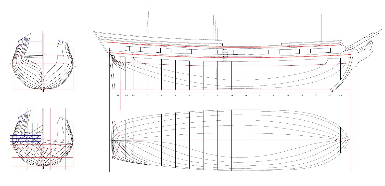
Thinking on the Forfait/Sané discussion of Java/Renommée and had an 'oh gosh' moment.The sterns of French ships were straightened up, along with the tumble home, after 1805, and things got squirrley. Been using the Rochefort draught of Justice as a model, but have some newer and more detailed draughts that I use for 'fiddly bits'. Unfortunately, I used the Erigon draught for the stern. Erigon was an 1811 Pallas class, built in Holland, and was a teensy bit out-of-school for Cornélie. So went back to the well. Took angle measurements of the Justice draught and Boudriot's Venus. Turns out the Justice was only a few degrees straighter than Venus (5 degrees), but significantly more relaxed than Erigon (10 degrees).Woof !!! So did the CAD thing and tilted everything out, and stuck an extra pane in the lights, and lined things up like they should be, and made sure there was sufficient space between the central lights to put some Egyptian columns in the filials. Ok, so here's the push: I just thought if I was going to put a classic 1800 head on her, it made sense to put a classic 1800 stern on her, as well. John
-
Frégate d'18 par Sané , la Cornélie
JohnE replied to JohnE's topic in CAD and 3D Modelling/Drafting Plans with Software
Hi, uss frolick. There were a bunch of 18pdrs built at Nantes. The yard was in the commune of Basse-Indre which was roughly 8 km downriver of Nantes. There was 1 x Lamothe, 2 x Gautiers, 3 x Forfaits, and 6 x Sanés built and launched by 1808. You would have 10 x Sanés by going to 1812. Créole, One-off design, Lamothe, launched 1797 Uranie, Clorinde - Uranie class, Gautier, launched 1800 Belle Poule, Surveillante - Virginie class, Sané, launched 1802 Gloire, Gloire class, Forfait, launched 1803 Président, Gloire class, Forfait, launched 1804 Topaze, Gloire class, Forfait, launched 1805 Pallas, Elbe, Renomeé – Pallas class, Sané, launched 1808 4 more Pallas class, Sané, launched between 1810 and 1812 Then there were some built in the commune of Paimboeuf, on the south bank, about 30 km downstream of Nantes and about 10 km upstream of St Nazaire. I include these because the yard governance was the same and they shared staff. Clorinde – Pallas class, Sané, launched 1808 4 more Pallas class, Sané, launched between 1810 and 1813 You can do a nice comparison between Sané and Forfait from the Chaumont Papers (SHD, Vincennes and Rochefort). Jean-François Chaumont was an Ingénieur, whose career extended from 1793 to 1828, at Brest, Rochefort, La Havre, ingénieur à la direction des constructions at Rochefort and Cherbourg, and directeur des constructions at Lorient. He made many of the drawings himself and they show not only the plans received by the dockyards, but also details of the yard’s implementation. They were, in effect, his ‘book’. The Forfait is of Venus and Junon; both Gloire class, like Topaze, but built at Le Havre (launched 1806). The Sané is unidentified. There’s lots of interesting things in the comparison that may help identify vessels as to ‘design style’, if not ‘designer’. Body sections are an obvious difference (‘apple’ vs ‘heart’), and the difference in bow waterline fullness is apparent on the half-breadths. The bilge area was what I was pinging on when looking at the bow oblique photo. But there’s some other differences, too. Contrary to what I have heard, Forfaits had deeper tumble-home than Sanés, at least after Sané’s 1802 Hortense class. Also (still being contrary) the rake of the stern face is darn near the same (within scale measurement limits). One really helpful aid is examining the bowsprit steeve. Forfait went early to a 20-22 degree steeve, with the bowsprit stepped on the main deck. Sané kept to the traditional 28-30 degrees, with the bowsprit stepped on the lower deck (at least till 1810 when steeve got lowered). One has to be careful with this, since the RN ‘always’ (inter alia) reduced steeve of captured French ships, so the provenance of a plan must be considered. The Forfait drawings show two different transom timbering configurations. One has vertical transom timbers (the body plan); one has traditional horizontal transom timbers (the aft profile plan). Not of interest, here, but notably, one can see his vertical stern timbering (same on both iterations) and see exactly where the 8 lights come from (clearly #1 and #8 are false). Seriously cool stuff ! The French archives are an intellectual ‘feast’, laid out in front of a starveling ! I have a bunch of Chaumont papers in my stash, but not these. I shamelessly scanned the images from my Boudriot book on French Frigates. [edit] posted more on the 'plans and research' thread. Thought it more appropriate. Ciao. John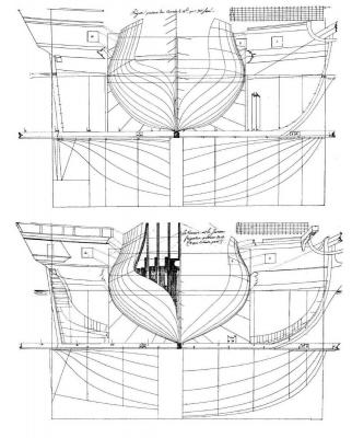
-
Frégate d'18 par Sané , la Cornélie
JohnE replied to JohnE's topic in CAD and 3D Modelling/Drafting Plans with Software
Yeah. I would love to continue this. It's kinda like meat and potatoes. I would like to participate in that. I was just doing a bit of critical thinking on what I could see on the photos. Critical thinking gives no answers. It just tends to help to keep us from ... um ... er ... well .. sticking our winkie into the windmill. Sincerely hope I did not offend. John -
Frégate d'18 par Sané , la Cornélie
JohnE replied to JohnE's topic in CAD and 3D Modelling/Drafting Plans with Software
Well, they say digression is often good for the soul, so what the hey. Went to the Museum collection and looked closely at the photos of La Renommée. Putting the good old Eyeball, Mark-1 to work, I found some things worth noting. I do believe the oblique bow photo suggests a more ‘apple’ shape than a ‘heart’ shape. There’s shadows at the turn of the bilge in the midships region. I think these shadows are more consistent with the ‘turn of the bilge curve’ of the ‘apple’ shape than with the relative straight bilge definition of the ‘heart’ shape (which would turn higher, generally in the neighborhood of the upper part of the green crud). I look at the hull and see more ‘apple’ than ‘heart’, but that’s completely subjective. Yep, the model depicts a beakhead. Bottom left, you can see (barely) the catheads and the cross piece, with the bowsprit entry below, but on the same vertical station plane as the catheads. Bottom right shows the forecastle and way up in the upper-left corner, one can see a darkish blop that is the cross piece for the catheads. You can see bollards and the first drift rail up to the fore mast, but then open space. Not consistent with a round bow. I know the ‘real’ issue has to do with her stern: 7 lights or 8 lights, and what’s-up with the angularity at the outside edges and the open railing. I’m as much at a loss as anyone on this part. But basically, the model is pretty much a Sané, in my humble opinion. John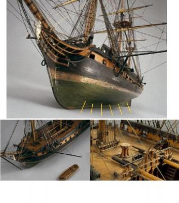
-
Frégate d'18 par Sané , la Cornélie
JohnE replied to JohnE's topic in CAD and 3D Modelling/Drafting Plans with Software
Hi. Bava, uss frolick. A while ago, uss frolick asked the question and I was getting stuff from SHD and so ordered a copy of that particular Renommee plan to see if it might be useful to him. It wasn't much help at all. Here's what it was. Your typical Sane hull outline with nothing as to stern (or anything else) detail. Sorry I couldn't be more helpful. I have no position on her provenance, except to note that she was on the lists as a Sane frigate, and the dockyard has her drawing as a Sane frigate. There is nothing to indicate otherwise except the museum model. In his books, Boudriot mentions that many models "were not as accurately identified as they could have been". Ya'll's guess is as good as mine.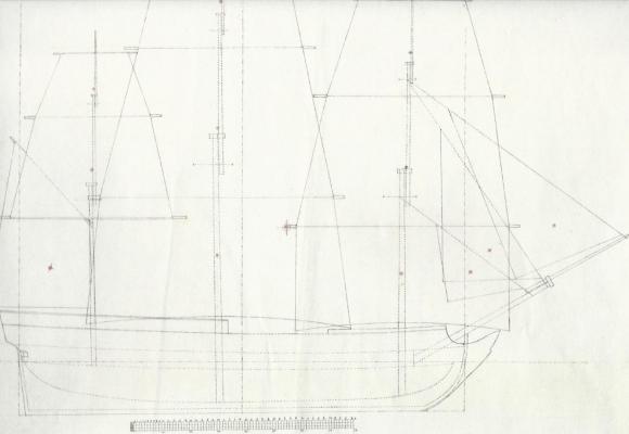
-
Frégate d'18 par Sané , la Cornélie
JohnE replied to JohnE's topic in CAD and 3D Modelling/Drafting Plans with Software
You are not wrong, Mark. There is some confusion in this and I’m afraid I am causing more. Trying to say much with few words is a recipe for disaster. Pierre Morineau and Blaise Ollivier both lobbied hard (in the 1750s) for the reintroduction of bridle ports since their fall from grace in the early 1700s. It was a local structural weakness issue that had many designers worried, but not so much some others. There were plentiful examples of vessels with bridle ports in the mid 1700s that did not exhibit worrisome structural weaknesses. Time passes slowly in the ancien régime and thirty years later … . An Instruction of April 1787, from the Ministry of Marine, inter alia, “regularized” the new gun Ordonnance of 1786, and included dimensionality, spacing and positioning of the consequent ports. It “recommended” (technically, ‘authorized”) inclusion of bridle ports in both liners and frigates, and provided a mathematical rule for positioning of a bridle port and redistribution of the others when [if] it was incorporated, clearly anticipating the alternative. It remained to be seen if the Ingenieur-constructeurs would adopt them. For example, a Ministry Instruction of 1778 ordered no more poops in frigates and dismantling of those already in place. We all know to what extent this Ministry Instruction was respected in practice. It took till the Regulation of 1807 to finally and affirmatively abolish frigate poops and roundhouses and it only did that by the expedient of adding guns (more iron 24pdr carronades) to the quarterdeck armament. The best way to think of mandates is look at a designer’s “devis” for a vessel or class. They pretty much all went with bridle ports for vaisseaux so it’s natural to think of this as a general ‘mandate’. Notably, the majority didn’t put them on frigates. The Regulation of 1807, in effect, ‘regularized’ standard practice of the preceding 20 years and put bridle ports on vaisseaux but was notably silent on frigates. Sané’s regulation of 1810 (which wasn’t really a ‘Reglement’) is quite clear that the first main deck port was positioned at, or about, forward station VI. But that was for Sané. Other designers thought and instantiated differently. Vial du Clairbois is my bible on this (particularly his 1805 reprint, with annotations) and Jean Boudriot is the modern testament. I consulted such relevant documents that I could find in the archives of SHD and SHM, Vincennes, but concentrated on 18pdr frigates. I’m certainly not saying I know anything. I’m way not that good, but I have drawn some factoids and inferences from the period sources. Any lapses, errors, or inappropriate snarkiness, is my fault alone. John -
Frégate d'18 par Sané , la Cornélie
JohnE replied to JohnE's topic in CAD and 3D Modelling/Drafting Plans with Software
Ok, think we are done. Have a special box for Monsieur Druxey's le sabord flottalt, because he is so enamored of him/her.Think it is time to move this thread to somewhere 'higher'. It's no longer a 'how-to' with CAD. Any comments are more than welcome. John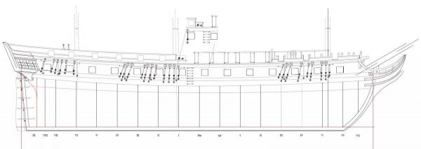
-
Frégate d'18 par Sané , la Cornélie
JohnE replied to JohnE's topic in CAD and 3D Modelling/Drafting Plans with Software
You are quite right, except I wouldn't say 'frigates'. It's a translation and usage thing. Vaisseau translates generally to vessel or ship (bateau, navire) but in the period we are talking about, 'vaisseau' had a specific meaning; a 'ship' of the line. i.e., 74 guns and up. In the period lexicon of la marine, frégates were differentiated from vaisseau. In 1787 bridle/chase ports were mandated for 'vaisseau'. Some people do the translation and think, ok, ships. Not so. Pierre Morineau lobbied for bridle ports on frégates but it didn't happen. Witness over 130 frégates built in the Revolutionary/Empire period with only a few, designer specific, instances of bridle ports. Bridle ports did not become a feature of French frégates until after the Restoration; Reglement of 1823, if I remember right.Till then, it was catch as catch can, with the vast majority living without. John -
Frégate d'18 par Sané , la Cornélie
JohnE replied to JohnE's topic in CAD and 3D Modelling/Drafting Plans with Software
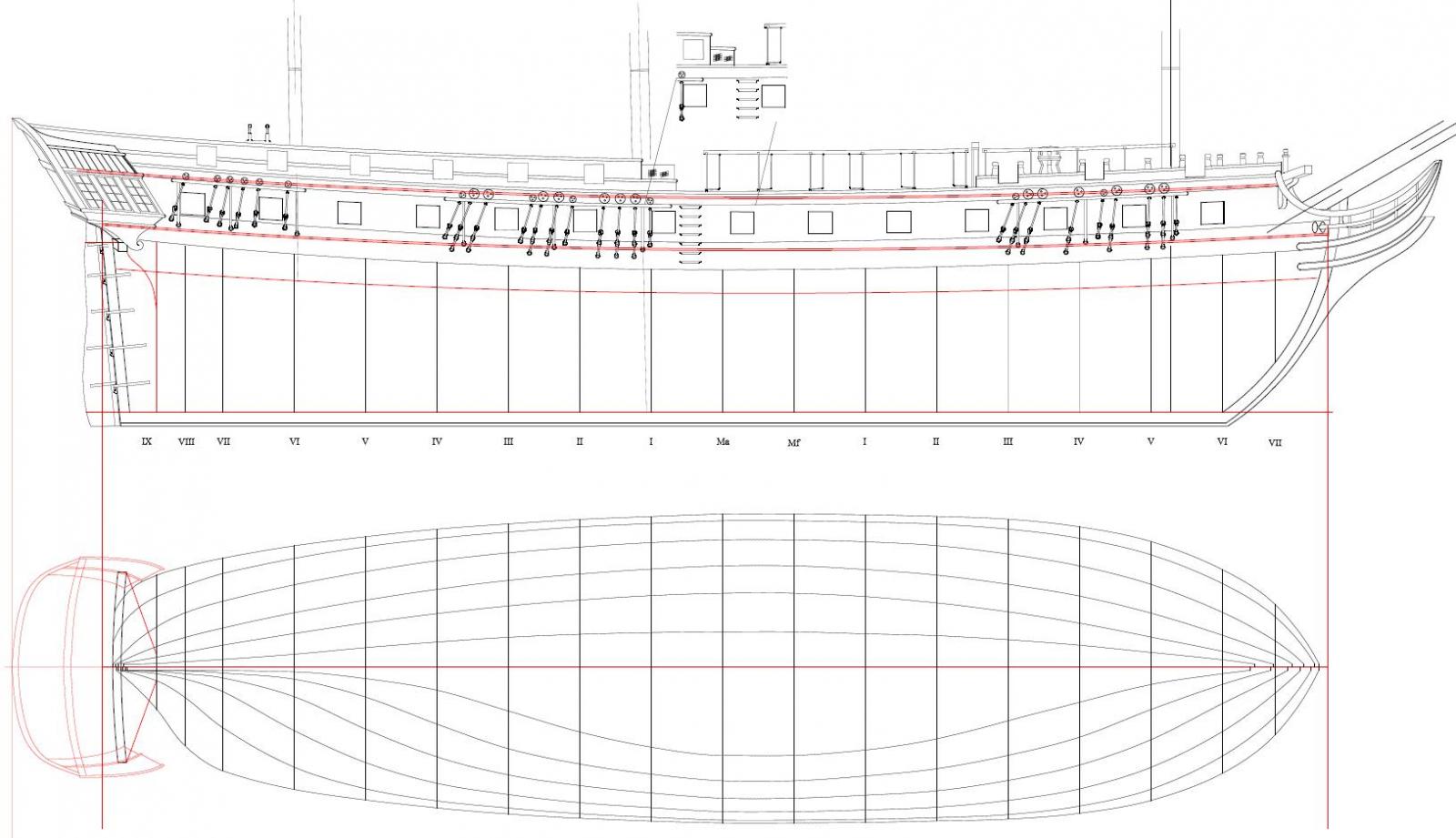
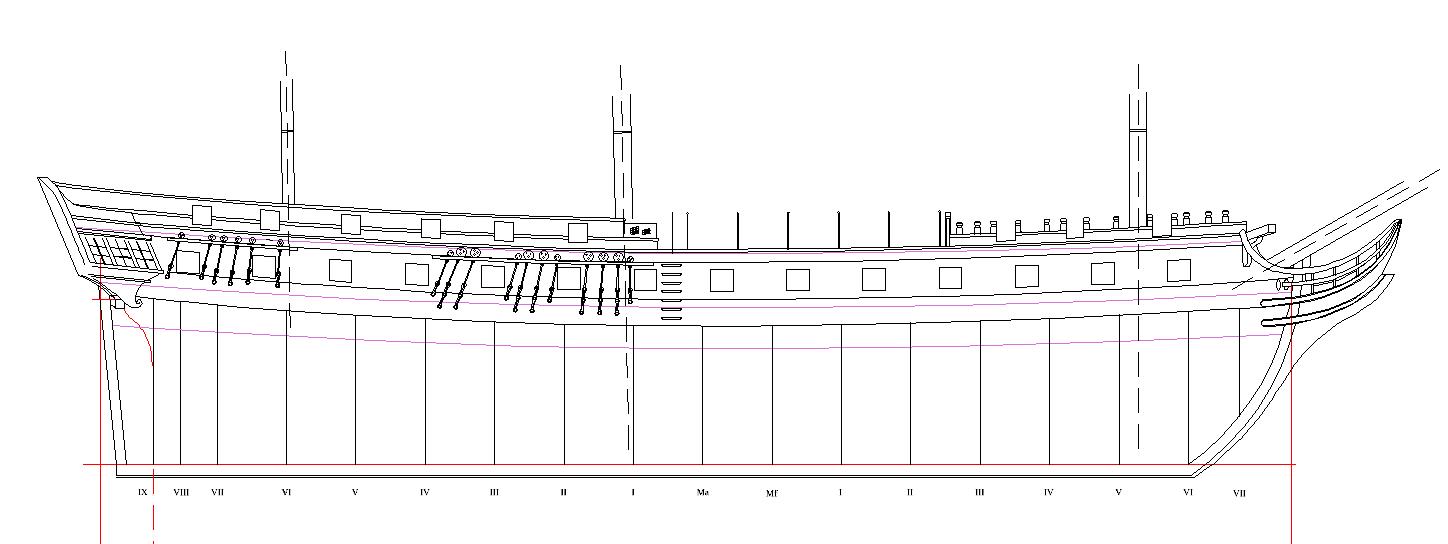
Ah ! Le sabord flottant ! It floated down to a home on the gaillards. I decided to press on with an armament suite according to the 1807 establishment. That would ideally be 6 x canons de 8 and 6 x caronades de 24 on the quarterdeck and 2 x canons de 8 and 2 x caronades de 24 on the forecastle. This armament suite was often seen before 1807 and the establishment is sometimes viewed as a unification and codification of existing practice. Even so, the ‘rule’ wasn’t hard and fast. Captains had latitude to position pieces where they wanted and even make substitutions or take on a couple more pieces if it didn’t hurt the sailing qualities too much. Position allocation depended a lot on the design (i.e., the lines). For example Forfait’s designs, while noted for their sharp deadrise, had relatively full bow waterlines. This added volume (buoyancy) in the bows and allowed a long gun to be positioned right forward if desired. In contrast, Ozanne had very Sané -like midship sections, but his bow waterlines were notably sharper. He compensated by reducing the rake of the stem, but while the designs were nice and weatherly, there remained a marked sensitivity to weight right forward. Oddly enough, it was Ozanne who commonly pierced fifteen on a side by adding an empty bridle port; one of the very few frigate designs in which this appears. Thus, after all the foregoing blithering, the quarterdeck is pierced six on a side. They were mostly (the last 4 aft) of a size for soit un canon ou une caronade. All had provision for the fighting bolt through a notch at the sill bottom edge. Technically, the two ports in way of the main chains were always armed with 8pdrs because of their muzzle extension beyond the shrouds. I’ll have 8pdr ports shown here in dotted outline, but it really is dealers choice. The forecastle has a center 8pdr port in way of the chains, ‘flanked’ by two 24pdr ports. Only one of these is filled in practice (typically the after port) but both are available if the Captain desires to move the after pair of caronades or shift a pair from the quarterdeck. The forward port is commonly kept clear to allow the crew to get at the bollards/timberheads for anchor and fore-triangle sail handling. As to ‘le sabord flottant’, there is a home for it. Some ships had a seventh port cut in the quarterdeck in the area of the tack fairleads. When this was done, the entry ladder (and hammock railings) moved forward to the line of the aft maître. Tack fairleads would have to move forward accordingly (can’t go aft because of interference with main shrouds). So, ‘le sabord flottant’ will live on. Anyway, that’s my story and I’m sticking to it. The info comes from many sources, but my main debt is to the works of Jean Boudriot. I can imagine him having a nice evening sail with Sané, Guignace, Morineau, Coulomb, Vial, et cie, and chuckling at my presumptions. Enchiladas were yummy. John -
Frégate d'18 par Sané , la Cornélie
JohnE replied to JohnE's topic in CAD and 3D Modelling/Drafting Plans with Software
Ok, more progress. Lions and tigers and chains, oh My! Making enchilladas and the timer just went off, so will explain later. John .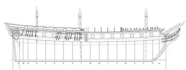
-
Frégate d'18 par Sané , la Cornélie
JohnE replied to JohnE's topic in CAD and 3D Modelling/Drafting Plans with Software
Thanks. Roll Tide !!! Et, Bonne Année à tous. Hey War Eagles, next year wil be better. I promise. Rooting hard for the Tide, but wearing an orange shirt. John -
Frégate d'18 par Sané , la Cornélie
JohnE replied to JohnE's topic in CAD and 3D Modelling/Drafting Plans with Software
Been thinking and there’s no reason at all not to do two separate profile details. Although individual ships were tricked out (armed) in various fashions, there were only two official “systems” in use, allocated in accord with several ‘reglements’. This, in turn, determined where and how the ports were pierced, and distribution of the corresponding chains/shrouds. The main early armament suite was on the 1790 ‘reglement’ using the 1786 gun ‘system’. This comprised: 28 x 18pdrs with vessels nominally pierced 14 ports per side, but some (notably Forfait designs) having a 15th (empty) bridle port. The bridle port was made functional by shifting a broadside gun. 10 x 8pdrs nominally disposed 8 on the quarterdeck (4 per side) and 2 on the forecastle. The forecastle was pierced (structured, actually) for 4 guns, but due to concern for bow weight and inertial moments, only 2 were ‘authorized’ and carried in practice. 4 x 36pdr sea-howitzers disposed on the quarterdeck (2 per side) ‘aft’ of the 8pdrs. Provisionally, one pair of these might be installed in the forward-most of the two sabord positions of the forecastle. Note-1. The crews (gunners) hated the howitzers. They were a direct copy of the land pattern and designed to fire shell. The gunners found that modality more dangerous to themselves than the enemy, so the sea-howitzers were provided with solid shot and canister. Good for the gunners, absolutely lousy for accuracy and, thus, effectivity. Note-2. Several vessels (notably Forfait designs) went with 12 x 8pdrs and no howitzers. Because Forfait’s model was so fine in bow and stern sections, these were primarily short pattern 8pdrs which were 325pds lighter than the long pattern (2056 vs 2382). That’s 25,000 lbs vs 27,000 lbs (including the howitzers) for the nominal armament, i.e., a practical difference of the weight of 1 gun. Oh yes, the French were very concerned with weights and moments and metacentrics. The main later armament suite was the 1807 ‘reglement’ using the 1804 ‘system’ which comprised the 1786 pattern guns and the 24pdr and 36pdr iron ‘carronades in place of the brass howitzers. This comprised: 28 x 18pdrs with vessels again nominally pierced 14 ports per side, but some (again notably Forfait designs) having a 15th (empty) bridle port. The bridle port was still made functional by shifting a broadside gun. 8 x 8pdrs nominally disposed 6 on the quarterdeck (3 per side) and 2 on the forecastle. 8 x 24pdr carronades divided between 2 pairs on the quarterdeck, again ‘aft of the 8pdrs, and 2 pairs on the forecastle ‘bracketing’ the central 8pdr long gun. Gaillard piercing was the same (except in certain dimensions) as in the 1790 ‘reglement, except for an additional carronade sabord at the after end of the forecastle. Note-1. The initial 1804 ‘system’ had 36pdr carronades, but their weight was found to be excessive (2232 vs 1543 for 24 pdrs). They were replaced with 24pdr weapons in the 1807 ‘reglement’ and were no longer manufactured by 1810. Woof, didn’t know I knew all that till I had to write it down. John -
Frégate d'18 par Sané , la Cornélie
JohnE replied to JohnE's topic in CAD and 3D Modelling/Drafting Plans with Software
I like your thinking uss frolick, since I'm working off an 1810 devis of a 1795 original. I think I would rather have her fitted out in a mid-Napoleonic suite. This is quickly becoming a Frégate d'18 par Sané et modifié par Mr. la Drague (moi). Oh, yes, chains and shrouds and bears, oh my !! That's the purpose of the question, because it defines all those fiddly-bits for the profile plan. I know Brits love him, but I take James with more than a cup of Kosher salt. He is supremely arrogant and nationalistic and gives me rectal infarctions. Like Teddy Roosevelt, I don't trust a word he says once he launches into his "why we won (or lost)" stuff. His armament crap is just that. Sorry, but .... I would much rather go with official French sources and journals of the captains, than anything that man has written. John -
Frégate d'18 par Sané , la Cornélie
JohnE replied to JohnE's topic in CAD and 3D Modelling/Drafting Plans with Software
Ah, yes, the famous flottant sabord.. Guaranteed to twist your kilt. Have a little problem, though. In early days, armament was different from later days, on the identically same ships. Just before the Revolution, a frigate would nominally have 28 x 18pdrs on the main deck and 8 - 10 x 8pdrs on the gaillards. French didn't rate ships on number of guns, but rather caliber of the main battery. That's why you see French frigates rated as 36s or 38s or 40s or 44s, all on identical hulls.. The 1793 devis of the original Cornélie lists her with 28 x 18pdrs on main deck, 10 x 8pdrs on gaillards, and 4 x 36pdr "caronades", specifically "sur le gaillard d'arriere". Life goes on and in 1807 there was a 'Reglement' that set an 8x 8pdr and 8x x 36pdr standard. Who did what to whom and when is entirely unknown, but the regulation is out there. Period records talk about ships having a pair of 8prds, flanked by "caronades" on the forecastle. Ok, so that's 2 x 8pdrs and 4 x 36pdrs on the bow and 6 x 8 pdrs and 4 x 36 pdrs on the quarterdeck. So what do I choose? I have my predelictions, but would rather rather have input from 'higher'. Ya'll got any? John -
Frégate d'18 par Sané , la Cornélie
JohnE replied to JohnE's topic in CAD and 3D Modelling/Drafting Plans with Software
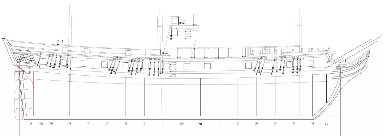
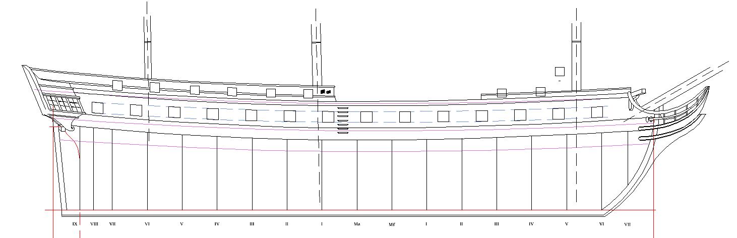
Thank you very much, druxey. Your appreciation warms the cockles of my heart. Again, thank you. So, off to prettiness. Here's a work in progress Profile Plan. Lots to do, still, Have to do projections of frames up to top-timbers on the forecastle for bollards and the actual placement of the sabords dans les galliards. And then there's midship rails, and such, Mostly later model additions, so will be in dotted-lines. Yep, rudder will be included along with fixturing. Anybody else out there that wants to see something? I been mostly talking with the Pros-From-Dover, but welcome and encourage input from anyone.. John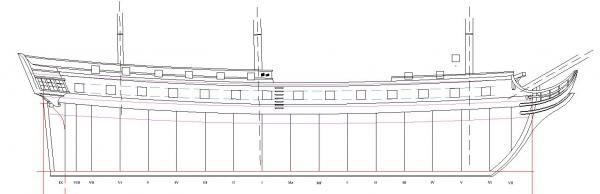
-
Hello Tom. Yes, Ancre will help you. So too will Gerard Delacroix at Marine et Modelisme D’Arsenal - http://gerard.delacroix.pagesperso-orange.fr I have found that French warships were much of a muchness, as regards fittings. A frigate would have many of the same boats as a 74, excluding the larger barges. Jean Boudriot has a nice section on ship’s boats in his volumes on the 74 gun ship. It’s available in English and Italian but, unfortunately not in German. There are rigging treatises, with info just like Steele, but they are in French. Small interest by the English speaking world means most have not been translated. Boudriot has a section on rope-work in his volumes on the 74 gun ship. These will scale to a ship of the frigate class very easily. John
-
Frégate d'18 par Sané , la Cornélie
JohnE replied to JohnE's topic in CAD and 3D Modelling/Drafting Plans with Software
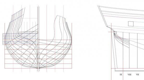
Thank you very much, druxey, but the thumbnail doesn't really do it justice. I did some cleanup and polishing with my old trusty Eppler Keel Analysis program and got things a teensy bit tighter (and prettier). This sub-forum is about using CAD, after all. Made a nicer capture that avoids the reduction blivets. Hope you like.