JohnE
-
Posts
309 -
Joined
-
Last visited
Content Type
Profiles
Forums
Gallery
Events
Everything posted by JohnE
-
Frégate d'18 par Sané , la Cornélie
JohnE replied to JohnE's topic in CAD and 3D Modelling/Drafting Plans with Software
I’m satisfied with the lines, so off to part deux: disposition of frame. First though, I want to put the outline of the stern elevation on the body plan and add the stern pieces/outlines to the half-breadth plan, but I’m afraid of making them too busy. There’s a ton of extraneous lines/marks on them already. Am thinking of just doing a simplified, curves only, body plan with the stern elevation outlines. Same with the half breadth; I’ll reproduce it up to the aft maître and only show half the waterlines. That should keep things clean enough for the stern portions to show up clearly. Ya’ll think that’s ok? My artistic skills are somewhat (totally) deficient, so the stern elevation will be empty. The wood between the windows is carved as roman columns, I can do those, but you must imagine some fancy scroll work below the windows and a spray of open rose buds along the horseshoe. That won’t take long, so I’ll work on it in tandem with the disposition of frame. When I get bored/frustrated with one, I’ll just switch off. John -
Hi Mark. Just catching up myself, after a hiatus. Was laughing pretty hard at some of the posts. Yeah, been there, done that. Nice thing about having some other languages is you can cuss a blue streak as loud as you want and the Admiral just says 'ok, I guess that means you want the tuna salad?'. Keep on keeping on. John
-
Frégate d'18 par Sané , la Cornélie
JohnE replied to JohnE's topic in CAD and 3D Modelling/Drafting Plans with Software
Bava. You have the right idea. Looking at it in 3D is definitely a good way to go. Pictures are indeed worth many words. Vial's drawings, in posts 41 and 47, are very good, but the ability to rotate an object and visualize in 3D is often priceless. He should have taken the oportunity to upgrade to TurboCAD 18 at the special introductory price . There are several pages of sailing qualities description in the Cornélie devis, but I haven't slogged through all of it, just hit the high points. Her captain, Villemaurin, was apparently a superb example of a highly trained, experienced, intelligent, and scientific sailor. He set up the trials to gauge performance at various trim and loading conditions. The devis has Sané’s tables of the conclusions, with marginal notations. Villemaurin also messed with rake and sail combinations but, unfortunately, his tableaux des voiles has not come down to us. Under best conditions of trim and load, she was quick in stays, neither griping nor making undue leeway; her roll was slow and relaxed (not stiff) but not too deep (not tender, either) making her an excellent gun platform. She wasn’t exceptionally fast at any point of sail, but she was ‘more than adequate’ at all of them. She was very weatherly in all breezes up to a ‘strong breeze’ (because everyone had different words for wind strength, I’m using Beaufort’s description of 1838 – strong breeze, 22 – 27 knots, i.e., force 6). Up to 25 knots, she held her gunports high and did not ‘wet her wales on the roll’. The sense I get is that, when correctly trimmed, she was quick, lively, and responsive in every degree. She had no blemishes. A sleek, lithe, graceful, beauty that Villemaurin loved and caressed and made into a swan. Sorry, got carried away there. John btw, edited the drawing in post 50, and made a note therein. -
Frégate d'18 par Sané , la Cornélie
JohnE replied to JohnE's topic in CAD and 3D Modelling/Drafting Plans with Software
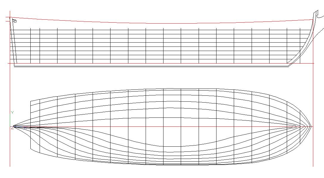
Ok, lines are done. Just have to do one more profile plan with the buttock-bows. These are very useful for planking purposes, but also for analysing the speed/length ratios, if you are looking at these hull forms with a modern naval architectural eye. Chapelle gives an excelent take on straightness of buttock-bow lines when crossing LwL. Given our modern understanding of form induced turbulence, he found a shorthand for a first-order rule that satisfies Froude very nicely. Druxey - You asked about this a while back, so the very lazy s curve in the aft end of the profile plan is the aft edge of the fashion piece when viewed from right orthogonal to Mr Keel. The angled lines, aft, in the top-down plan view are the cant-angle lines for the center of the fashion piece; viewed vertically, it is a canted frame, viewed horizontally, it defines a double curvature lazy s. Plot this puppy on a body plan (or even think about it for a second) and you will quickly understand why that last little curve, in the aft body plan, isn't a 'station', but a "projection" of a rotated/canted compound curve. Woof !! [ed] Oops, noticed a blivet. Replaced the drawing with the correct one. The 5th and 6th diagonals (4e and 5e lisses) were adjusted to terminate on the wing transom rabbet. Another Homer Simpson moment. John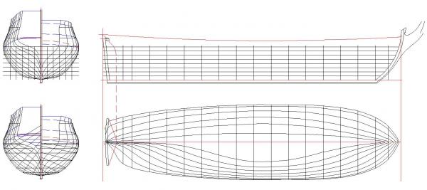
-
Frégate d'18 par Sané , la Cornélie
JohnE replied to JohnE's topic in CAD and 3D Modelling/Drafting Plans with Software
Horray. Eye patch came off this morning. Can see in 3D again and play with curves and such, so back to work on the lines plans. Never realized how hard it was to get a good sense of drawings with just one eye. Guess that’s why the old-timey pirates like John Silver always lost their treasure, even with a map. Aaarrgh !!! John -
Frégate d'18 par Sané , la Cornélie
JohnE replied to JohnE's topic in CAD and 3D Modelling/Drafting Plans with Software
Truer words were never spoken, druxey. I've been trying to model the stern (estain and ecussons) in 3D and then identify a plane and rotate things so they are rectilinear and I can take offsets. Woof ! Painful ! So I was rereading Vial and rediscovered the rest of his entire section on designing the stern. Was so intent on the wonderful hors-d'oeuvres, or the fish entrée, I neglected the perfectly cooked leg of lamb, plat principal. There's lengths, angles, detail up the wazoo, along with a nice description as to how it will project on a 3-view and an even nicer description as to the effects on a ship's lines by moving certain of the marks in-or-out, up-or down, fore-or aft. Dude, can you say Homer Simpson moment? Du' Ohh ! Moving along, Vial's stuff is for a 74, but the concept is still good for a frigate with some adaptation as to to scale. Will be paying more attention to Monsieur Vial in the future. John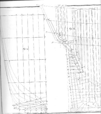

-
Igor, I am reminded that Siddhartha, too, was only a student. What you have created is truly magnificent. Not just the ship, but the shape of the bottle, the rocks, the setting, the perspective, the gestalt, and coup d'oeil. I think you have created a true work of art. John
-
Thank you for the pictures of sailmaking, Tadeusz. 50 years ago I would work my high school summers on the cutting floor at Hood Sailmakers in Tampa. The thread was a Dacron, but it was also heavily waxed. I used exactly the same glove, although we called it a sailmaker’s ‘palm’. It was used in the same way, to drive a big needle through multiple layers of sailcloth, including maybe a leather chafe piece. Even today, there is a need for heavy piece work and sailmakers still use this ‘palm’ along with waxed thread. Funny how some things never change. John
-
Frégate d'18 par Sané , la Cornélie
JohnE replied to JohnE's topic in CAD and 3D Modelling/Drafting Plans with Software
Wing transom is 13 pi thick, top-to-bottom, and 11.5 pi fore-and-aft. This is from Morineau and a bit old; but Vial tends to agree 30 years later (13 x 12 pi). It rounds aft by 1/3 of its length, reduced to inches, making the round-aft about 7.5 pouces (7.33 pouces according to another methodology). It rounds up as for beams, in proportion to its length. This would have the wing transom round up about 5 po (4 po, 7 li according to another methodology). I went with 7 po, 6 li, for round-aft, and 5 po round-up. Know exactly where the wing transom went (according to the devis), so plop it in. Sane has 4 filling transoms (early ships may have had 3, c.f., Virginie), Forfait used 5 thinner ones (c.f., Amazone), where he didn’t use vertical transom timbers (c.f., Junon). Sane’s cant angle was typically 20 degrees. From Morineau and Vial, we have the different displacement angles of the filling transoms and their lengths (their spans actually, ouverture in French terms), so we can do the line of curvature on the profile plan, and use a 20 degree cant line. Everything is working very nicely. Lines coming soon. Thank goodness for CAD ! John -
A loooong time ago I sailed with Dennis on Freedom for the quals, as trimmer. Anything to do with the old America's Cup boats makes me perk up and take notice. I've seen lots of J-Class boat models, but never one that can sit on your fingertip. I do not have the words. John
-
Good to see her getting some clothes on . Watching, listening, learning. Like Carl, I'm waiting for the sanded version. Top stuff. John
-
Frégate d'18 par Sané , la Cornélie
JohnE replied to JohnE's topic in CAD and 3D Modelling/Drafting Plans with Software
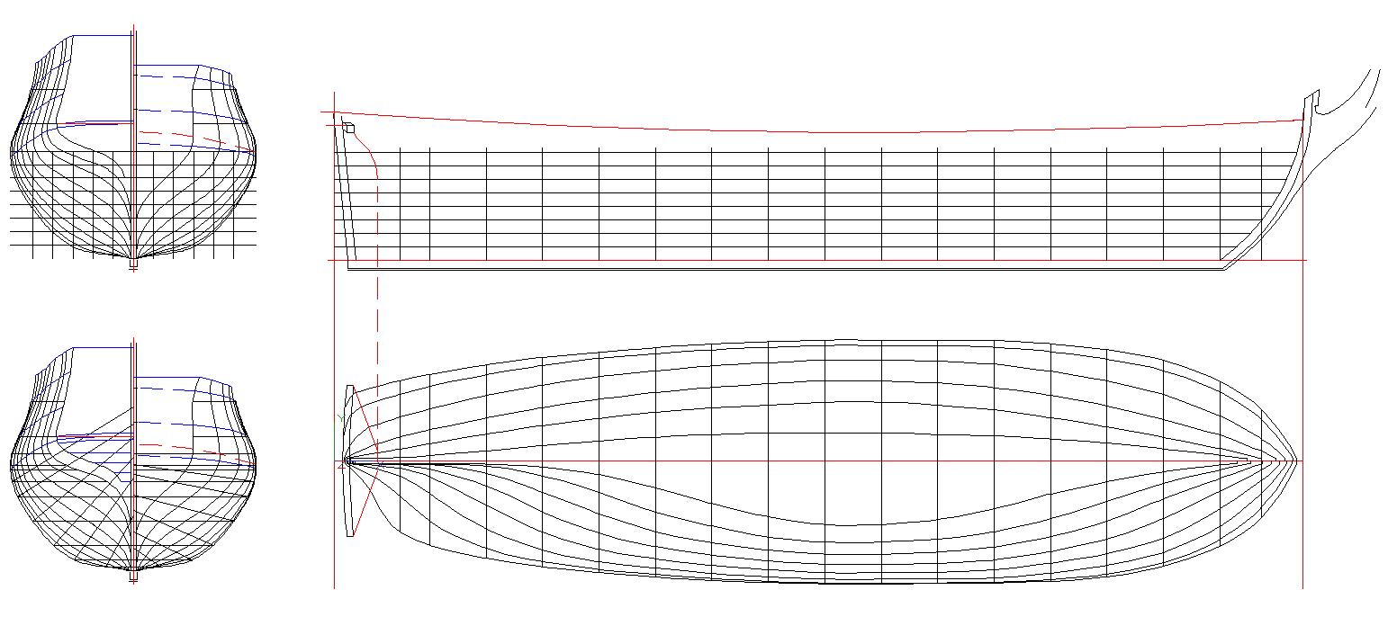
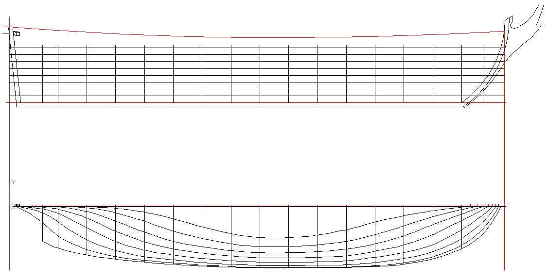
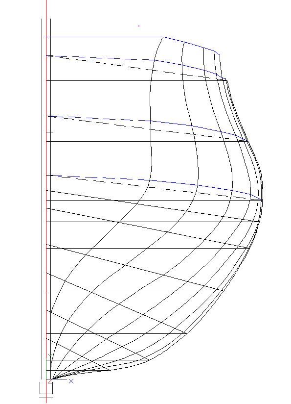
More progress. Here's the half-breadth; waterlines below, diagonals above. Diagonals look really fair. No hard spots at all. Easy planking. Going to have to loft the stern assembly in order to finish the lines, but they are good to go as far as they extend. I could just copy the buttocks and fake it, but I would rather put in the work to make them as consistent and faithful to the original devis as all the other lines. That's another reason for adding buttock-bow lines to the draught. You end up with a rational 3-view space, having definite orthogonal, cartesian, entry points. The buttocks can be modeled in a relatively straight forward parallelogram. Interior boundary points are from the specs of the wing transom, and all the filling transoms. Lines for planking runs can be superposed over endpoints. Where there is discontinuity, or impossible hardpoints, perhaps the stern timbers could be adjusted a bit (Oh ! The Horror !) to make things a skoosh smoother? Well, I did say I would be doing this like a yard dog would go about it. Can't imagine them mindlessly hewing to the instructions if it meant the sacrément bordé wouldn't take the curve. Happy Days. John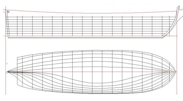
-
Frégate d'18 par Sané , la Cornélie
JohnE replied to JohnE's topic in CAD and 3D Modelling/Drafting Plans with Software
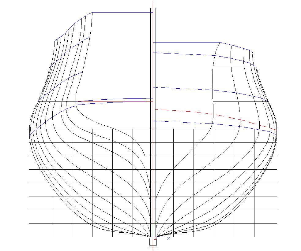
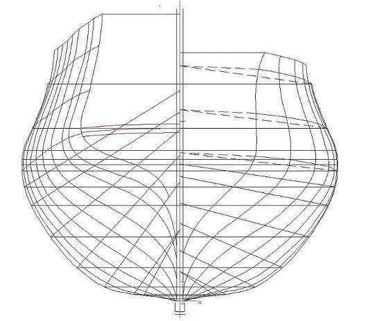
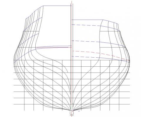
Druxy, it's kinda, sorta, the reverse. The upper part kinda, sorta, conventionally cants; it's a straight line, but the bottom is angled forward, and the whole magilla is canted - the top more than the bottom. The lower part has compound curvature in two major planes and has an angular offset, besides. Woof !! The next few days/weeks will hopefully make this clearer. Progress. Have waterlines for the little darling. They are horizontal, parallel to the keel, and spaced-apart by 2 French feet. They actually look pretty good. Diagonals are coming soon. I'm departing from French practice by defining a series of 5 buttock-bow lines, spaced-apart by 3 French feet, starting at the vertical centerline. I am reminded that the point of the exercise is to develop a plan set that can be used by modelers to actually construct one of these. Anyway, Mistress Cornelia, in her latest suit of clothes. And just for reference, here's the body plan with the marks. If there's one thing I have learned in this project it's discipline, encore la discipline, et toujours discipline. Ok, the lines get done back to the lisse d'hourdy and l'estain. Major project to loft the stern and get things righteous. Things will be good up to that point, and will get adaptively tweaked as life rolls on. Ciao. John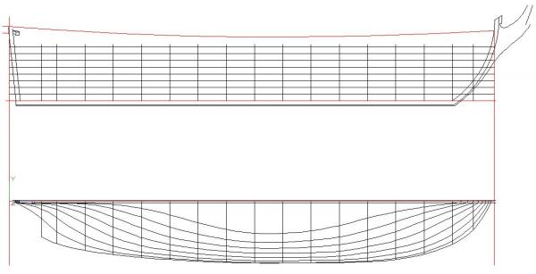
-
Frégate d'18 par Sané , la Cornélie
JohnE replied to JohnE's topic in CAD and 3D Modelling/Drafting Plans with Software
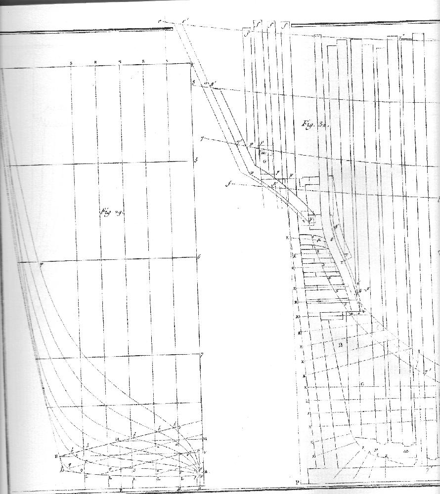
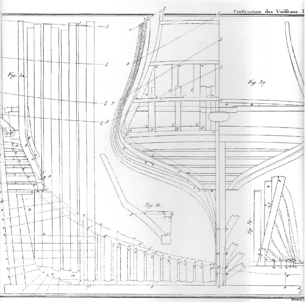
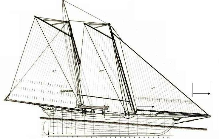
OK, got it working (sort of). You can see, from Bava's post, just how far off vertical the lines are in one direction, but you still can't see how canted they are fore and aft; that's the drawing in the bottom right and the subject of an entire figure in Vial's treatise that has circles and arrows and other evidence that will be used against us. Oh, by the way, all them little marks and lines and such are used in the design process. Vial has many figures of geometric tablature and extensive explanatory text sections. A very nice feature is that items in Vial have names that correspond, one-to-one, with items in the Devis’. The French did a lot with mathematics and it’s very apparent in Vial. Actually, it’s perfect for one using CAD to reproduce lines. Happy days. John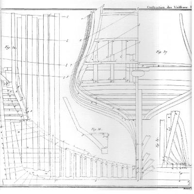
-
Frégate d'18 par Sané , la Cornélie
JohnE replied to JohnE's topic in CAD and 3D Modelling/Drafting Plans with Software
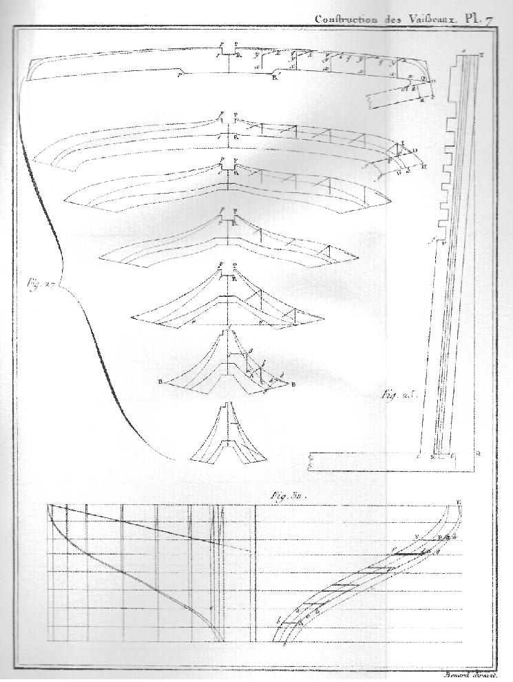
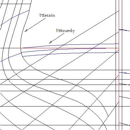
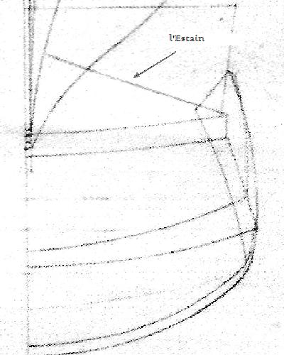
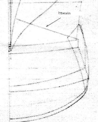
Bava, you did not derail, You make an excellent point that is right in line with the discussion. Please keep on contributing. Yes indeed, Druxey, it’s a projection. Bava’s post shows some of the ‘whys and wherefores’. Vial has a very nice section in his treatise about “Des Estains”, where he notes this and gives a caution . "Les estains sont les pieces de membrures auxquelles aboutissant les barres dont nous venons de parler (ed - Des Barres d’Ecusson) ; on voit l'un d'eux projete sur un plan horizontal en E e … . Aucune de ces projections n'en donne le contour au vrai, parce qu'ils ne sont, dans aucun de ces dessins, dans le plan du tableau." (Rough: The estains are the frames that abut the transom pieces. We see one projected on the horizontal (elevation and vertical) plan at E. None of these projections give a true outline because they aren’t in the plane of the design drawing.) All the other body plan lines are taken from vertical stations. When it comes to frigates, the French did not use cant framing and all of their "couples" were "square", from tip ta tail. However, although shown as a design curve on the body plan, l’estain is far from square and very far from vertical. This makes modeling the lines in the buttock region very exciting, when depending solely on the traditional plans. Here’s a scan from one of Vial’s Plates showing stern construction for a 74. You can see the two planes of cant, as well as the compound curvature at the base. Clearly, if the curved section were angled forward a bit more, the buttock planking run would be a bit more relaxed. Conversely, if it were viewed as more vertical, the buttock planking run would have an exceptionally hard edge to overcome. Woof !!! for some reason, the image won't load. I'll try again later. John -
Frégate d'18 par Sané , la Cornélie
JohnE replied to JohnE's topic in CAD and 3D Modelling/Drafting Plans with Software
Boy, howdy, am I learning about French ship design. A word of caution about the aft end of French ships. Station VIII is a vertical station, but station IX is not. Station IX is l’Estain, which is the trace of the lower portion of the fashion pieces of the stern. L’Estain is a compound piece: it is canted inward (lateral), but also canted forward (vertical). It is routinely shown in French plans, but as a guide, not necessarily as a line model. L’Estain is on traditional French Body plans; yes, but only as an aid – a projection of the exterior shape of a multi curved object expressed in rectilinear space. People more familiar with the British system of measurement can easily get confused with the French paradigm, particularly where ‘other’ measurement stations are adapted to National technical practice. People who use l’Estain as a vertical section will end up with impossible buttock curves. Realizing the lines are way more relaxed, both horizontally and vertically, can only help. There is a reason Monsieur Boudriot put his special buttock lines (a, b, c, d) in both his 74 Gun Ship and his Venus. John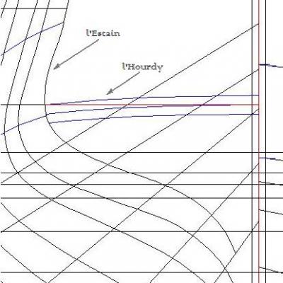
-
THE 74-GUN SHIP by Jeronimo
JohnE replied to Jeronimo's topic in - Build logs for subjects built 1751 - 1800
Me too, but I must add .. "exquisite". Jno -
Frégate d'18 par Sané , la Cornélie
JohnE replied to JohnE's topic in CAD and 3D Modelling/Drafting Plans with Software
The paradigm worked so well, I just had to show it. Ta Da, the Body Plan of my Cornélie. I was really afraid when it was time to put in the final marks, after doing the section curves. I dropped in the "lisse d'Hourdy" stuff from the devis and my hands were shaking, I almost couldn't click enter. Damn ! if it wasn't almost perfect !!!!! two tenth's of an inch after flowing in from the master couple, eighteen feet away. I am feeling very comfortable about my body plan. Actually, it's the body plan from the "Devis d'exécution des frégates La Justice et La Cornélie", dated March 1810 and signed by Jacques-Noël Sané, along with some visual assistance from a possible plan of this version of La Justice maintained by SHD Rochefort. Detailed references available on request. The Sané Frégate d'18 of the règlement, took its lines from the Virginie Class frigates Justice and Cornélie, built at Brest and launched in 1794 and 1797, respectively. So the lines of the paradigmatic "Justice" should work equally well for Cornélie. In an ahistorical note, the original ships had that abortion of a poop. I hate it. Jean Boudriot didn't like it either, but was kinder and just called it unaesthetic. The devis and the Rochefort draught profile plan are without this 'feature', and necessarily require some adjustment in the Rabattue and lines of l'Estain. So my Cornélie will have more flowing lines in the aft profile. John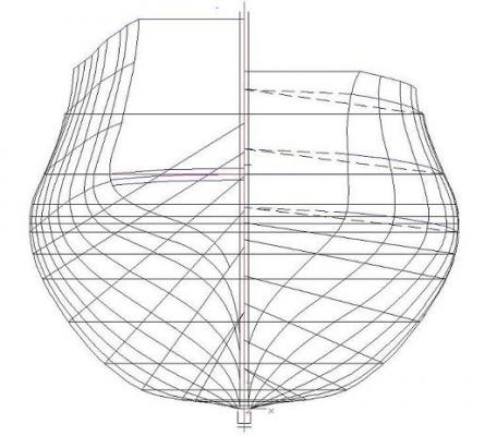
-
Frégate d'18 par Sané , la Cornélie
JohnE replied to JohnE's topic in CAD and 3D Modelling/Drafting Plans with Software
Ok, stopped widdlin’ and got to fiddlin’. Appended is the bow section body plan with construction marks and diagonals. If these ain’t the official plans they, sure as shoot, oughta be. Am in the midst of the stern sections and the paradigm is working perfectly. As a further check, I’m running a rolling half-breadth plan just to make sure that the body lines plot fair. I’m anticipating another day or two to complete the entire body plan. I should have a fair diagonal half-breadth plan when finished. Will post. Given this, a waterline half-breadth is a no brainer. I’m plotting at 1:12 with 4 sig figs behind the decimal. Boy, oh boy, does this project have a ton of Excel files !! Thank you Henri-Louis Duhamel du Monceau, Honoré-Sébastien Vial Du Clairbois, and Gérard Delacroix and Hervé Sasso who brought us all together and who provided exceptional assistance just when I needed it most. John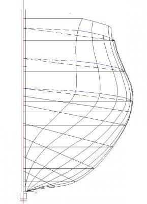
-
Yes, Sir. A jackline is an elegant solution. Thank you for posting that. I almost always find that them "old" folks had practical solutions that turn out to be "elegant", while we moderns grunt through the problem with tech. Given the prevalence of sails hoisted on 'horses' over decades and decades, I should not have been at all surprised. Thank you again for a most informative post. John
-
Have to start by saying I have no direct experience with this. Only boom or club footed sails I have used are staysails in cruising cutter rigs. They don’t have the problem you describe, so this is a by guess and by golly sort of comment. Deltrot beat me to it, but back in the 60s, Goudy and Stevens built a 130’ megayacht that was much of a muchness with America; a replica as best they could make it. It had two foretriangle rig options – a double headed, with jib and staysail, and the 1851 style, boomed, full area jib. What they did was attach the foot of the sail to the boom with hoops around the boom and attached to the sail through a cringle or grommet. The luff is attached by the usual hanks. To drop the sail, one eases the outhaul (or unhooks the clew snapshackle) allowing the foot of the sail to simply slide forward along the boom, making nice pleats cringle-by-cringle. But that was now, and this is then. There’s a contemporary French plan, undated, but titled “America” construit par Mr. Geo Steers that shows her with reef points on the jib. In order to take in a reef, they would have had to solve your geometry problem and let the clew forward by the same luff offset. This little factoid requires the conclusion that she had an adjustable outhaul with 15-20’ of tail. Then there’s a model by Dick Arpin/Dean Derusha/Milt Thrasher that shows a possible solution. The foot is secured to the boom by a rolling lash through foot grommets/cringles. Presuming a decent outhaul fetch, the rolling lash would function just like the Goudy and Stevens foot hoops when the outhaul is eased. Recall your force vectors on a jib/genoa. The foot is ‘relatively’ benign, so this stuff ‘could’ be done even while under way. Tucking her away for the night might make the crew sweat, but should pose no difficulties. I know this is not dispositive, but hope it helps the discussion. John

-
Frégate d'18 par Sané , la Cornélie
JohnE replied to JohnE's topic in CAD and 3D Modelling/Drafting Plans with Software
LOL. That sounds like something that Cartman would have said to Nero (sorry, a bit of South Park humour there) Found several places where I screwed up. Getting meticulous over all the data. My program is outputting some very pretty major arcs. The reconciling curves are fitting into place on the diagonals. Boy, oh, boy, am I learning a ton about French period naval architecture. Am happy with the bow sections in the body plan so far. Breathing a large sigh of relief, I'm off to do the stern sections using the same paradigm. If this works like I hope, then one more day will see a half-breadth of the diagonals, and one more will see a half-breadth of horizontal waterlines. Hootz, gazootz !! Anticipating the question from Gaetan, Gerard, and others, I am paying particular attention to "dehors des membres" and "dehors des bordages" data entry notes. John -
Frégate d'18 par Sané , la Cornélie
JohnE replied to JohnE's topic in CAD and 3D Modelling/Drafting Plans with Software
uss frolick, you are so right. The draughts are from somewhere else. However, the tablature is almost identical in every signifigant respect, so I have to wonder about those nice plans. Venus and the first Justice were very much of a muchness.They should show identical on an overlay. The second Justice (March 1810 devis) was Sane's definitive expression of the fregate de 18. He used the lines of the first Justice, and only tweaked the topsides. The devis of the Pallas class is identical in every respect to the 1810 Justice devis, except for 2-3 lignes in 2 places (2/12-3/12 of a French inch). A French friend sent me a monster plan and the devis, of Armide, a Pallas class laid down before the end of the war, but not launched till 1821. Her tablature, below the 6th ribband, is identical to the plan/tablature of the Justice from the Rochefort draught/devis. Their station plans overlay perfectly. So, as you say, to heck with published draughts. Sane wrote these devis, and some of them have notations in Sane's own hand, so you know it was his work. Don't know where the other plans come from. At this point, I don't care. Going forward. John -
Frégate d'18 par Sané , la Cornélie
JohnE replied to JohnE's topic in CAD and 3D Modelling/Drafting Plans with Software
Thank you Mark, but I have the Venus body plans in the plates of Boudriot's book. I only meant that they aren't quite in the same ballpark as the other two. John -
Frégate d'18 par Sané , la Cornélie
JohnE replied to JohnE's topic in CAD and 3D Modelling/Drafting Plans with Software
Oh, jeez. You know what they say about plans and the enemy? I screwed up. Then I did what Mark suggested, and made a spread sheet with calculations. I have French values (in decimal for easy entry into the drafting program) and metric. One can easily get from metric to English. Then I decided to stop beating away the alligators and drain the darn swamp; fired up my yacht design software, entered the offsets, and let her rip. It does multiple circular (elliptical) arcs where it finds them, and one only need delete a minor arc to get a reconciling arc substituted. And it exports in a TurboCAD compatible format. So we’ll see. From all the data I have, the body plans of the Venus are different (they aren’t in it). Needs must when the Devil drives, so my body and half-breadth plans will be taken from the historical documented offset values of the “Justice” and “Pallas” devis’ d’execution. Sorry for the confusion.