JohnE
-
Posts
309 -
Joined
-
Last visited
Content Type
Profiles
Forums
Gallery
Events
Everything posted by JohnE
-
Frégate d'18 par Sané , la Cornélie
JohnE replied to JohnE's topic in CAD and 3D Modelling/Drafting Plans with Software
Oh, golly, start in with l’estain and it just don’t quit (not that I mind, it’s just too legit). Ok, then, top down view: fashion frame was two pieces (in effect, a couple), the fashion frame was itself but had a forward support frame. The heel of forward fashion support frame sat on, and flowed into, the aft frame of the aftermost ‘square’ couple set (Bourdiot’s FF). The heel of the fashion frame itself might be viewed as also flowing into the line of FF, but down at the bottom, everything flowed into the deadwood (le massif). Notably, and unlike the station sections, the body plan line of the fashion frame (l’estain) is the after edge of the timbering (the red line). The body plan lines of station sections are taken from the center seam of the corresponding couple. The position of FF, in the image, is totally arbitrary. Its actual location and individual timber thicknesses will depend on design definitions of frame, room and space, and what the yard dogs had for breakfast. Anyway, this is the top-down view of the diagonals, based on everything else. The lines are now reconciled orthogonal to the other views. Please forgive my earlier attempts I was trying to replicate something that just didn’t fit within this paradigm. Sorry. I’ll get this into the plan set, as well. John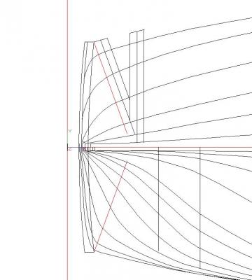
-
Frégate d'18 par Sané , la Cornélie
JohnE replied to JohnE's topic in CAD and 3D Modelling/Drafting Plans with Software
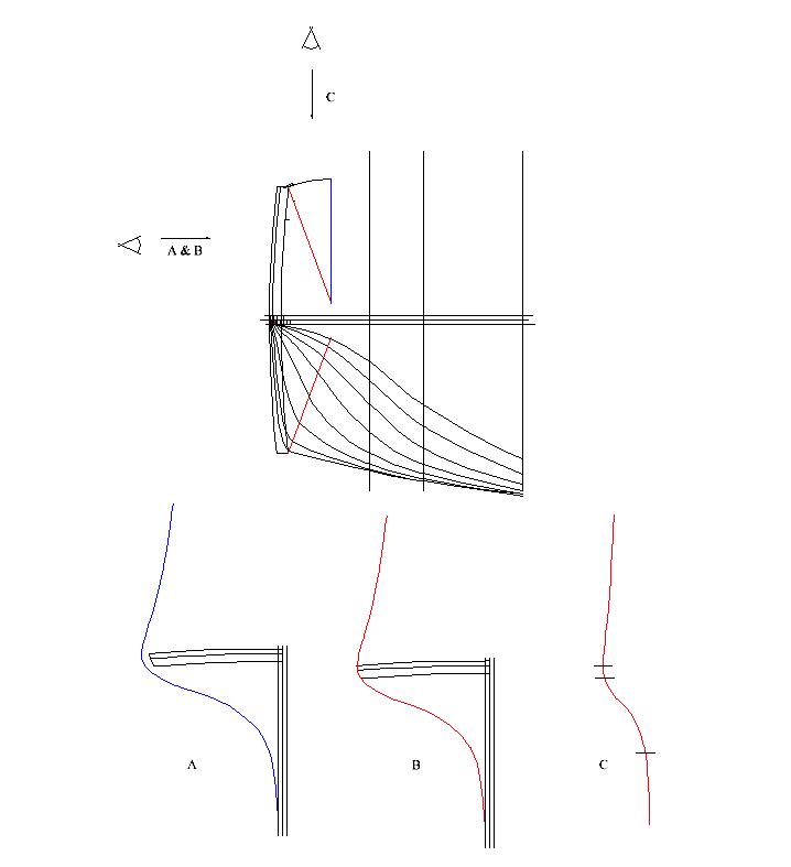
Hi Bava. The outside red line on the halfbreadth of the profile file is the line of gun/main deck. The inside red line is the line of gaillards.I have a little problem with l'estain, too. I feel your pain. Boy, oh boy; l’estain is a pain, yeah? Ok, some quick explanation. The fashion frame is simply a ‘cant’ frame, but expressed in the French fashion. It is ‘square’ in concept, but rotated aft by 20 degrees (or thereabouts). It was built super thick so that it could accommodate the compound (double twist) beveling from top to bottom (French were very profligate with wood). Diagram shows two view directions and what they give. “A” indicates l’estain, if erected ‘square’. “B” indicates l’estain after rotation through 20 degrees. Curve “B” is what is projected on the body plan. It’s basically a lateral scale of cos(20) – 0.9397 applied to the ‘square’ curve. Curve “C” is the lazy ‘s’ curve of l’estain that appears on the profile plan. The profile curve is snipped at pertinent parts and the ‘square’ curve is scaled laterally by sin(20) – 0.34202. That pretty much reconciles the two orthogonal views (body and profile). I’ll make sure this gets done in the plan set. Diagonals are another matter, entirely, and deserve a separate post with yet more illustrations and explanations. This is good. I would have to have done something like this in explanatory text for the plan set, but this is a better venue and allows for better organization of the final views. Please do not hesitate to comment. John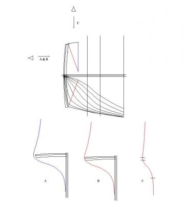
-
Frégate d'18 par Sané , la Cornélie
JohnE replied to JohnE's topic in CAD and 3D Modelling/Drafting Plans with Software
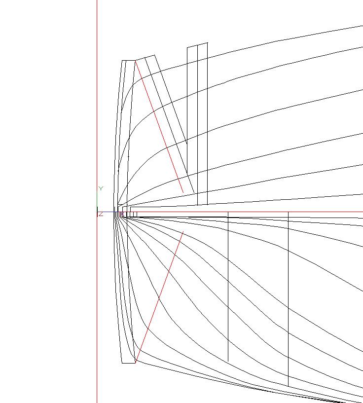
Reconciliation is going very well. I’m keeping extensive notes so when I have a senior moment, I can look up how I did something and why. So far, so good. However, I note some inconsistencies in the buttock region of the diagonals of the half-breadth. They are due primarily to “angular projection” of the fashion frame, the periodicity and center of the last ‘square’ couple (after VIII, but before fillers) and, most importantly, the perspective “view”. Buttocks of French ships are the least well described, and most often frustrating, portions of a model. French plans are rather inconsistent in their depiction of diagonal “view” as a function of other 3-space elements. Even the original sources, like Vial, pass it off. “Mediocrity will never do.” French had their own paradigms for plotting these lines, but that is of interest to historians. Model builders need something more substantive and determinative. So I went back to the well; back to the loaf of bread, actually. Chapelle (and Wayne Kempson) put it succinctly; just slice a bread loaf. Slice along the plane of a diagonal and you get ‘options’. First of all, that plane is not orthogonal to any specific point. It is vertically skewed in accordance with the design rule, so the diagonal line will ‘project’ accordingly. If you do an accurate top-down view, accepting the angular plane-of-cut, you will get one set of curves. These will be ugly in the buttock region, and not in accordance with French practice. Alternatively, once you get a diagonal “slice”, you can lay it down on the horizontal plane (making due allowance for stern to bow vertical shift). This gives another aspect to potential planking bend/flow in this critical area. I know this isn’t how the French did it, neither did the English. But this is the best I can do to present the plans of a representative French frigate in a way that modelers can understand and reproduce. Ok, so another half-breadth with another paradigm and buttock detail after VIII. It seems like my life has zeroed down to massaging French buttocks. That’s ok ‘cause my Admiral is a Chillena and has the perkiest buttocks in the world. John -
Frégate d'18 par Sané , la Cornélie
JohnE replied to JohnE's topic in CAD and 3D Modelling/Drafting Plans with Software
Ok, finished up the first pass at tweaking. Was reminded of what I have to do by something I saw on SawdustDave’s SoS thread quoting modelshipwright Bill. “Mediocrity will never do. You are capable of something better” – Gordon Hinckley. Darn good advice. I’ve been on Hinckleys. There may be a few other tweaks, depending on what people find and how the buttock line sets project in 3D, but I’m comfy with this as a basic set of lines. Basic plans are 1:48, English/US measure; have gotten pretty good with scaling algorithms, so can also do Pieds du Roi, Pies de Burgos, or metric. Now the fun/hard part begins.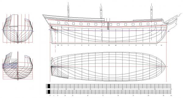
-
Seeking information on determining load waterline
JohnE replied to trippwj's topic in Nautical/Naval History
My friend, they used logarithms. They memorized the table of logs. A modern sliderule is nothing but a replacement for memorization. They used pen/pencil, paper, and their brains, along with a book of tables, if necessary. This was the age of d'Alembert, Bernouli, Euler, Fourier, Laplace, Lagrange, Gauss, Rolle, and a bit earlier Newton, Descartes, and Fermat. Mathemeticians that we moderns are, frankly, unable to comprehend without an "advanced" degree; and it took 358 years to solve Fermat's last, the proof of which he declined to put in the margin because it was a 'bit' too long. Don't ever make the mistake of thinking these people weren't "accurate" just because they didn't have computers or Exel. They had more practical math sense than I could ever hope to have, and I'm a physicist and naval architect. John -
I looked them up. https://bateauxminiatureslucleclerc.wordpress.com/historique/ Apparently three generations of Canadian model makers. Models in several Canadian museums and the Queen of England is noted as having one. Have no personal familiarity with the company and thus cannot comment on their model accuracy and the like, but can say that Les Bateaux Leclerc is legit. I would be comfortable purchasing their products. John
-
Frégate d'18 par Sané , la Cornélie
JohnE replied to JohnE's topic in CAD and 3D Modelling/Drafting Plans with Software
Boy, oh boy, talk about CAD being useful in design. I provided Bava, one of our forum members, with a scaled preview set of plans, so he could make a 3D model. Little did I know how interesting and valuable that would be. The plans contained some vestigial curves that were used as design aids but were not strictly part of the “official” plan lines. I simply plopped in something and used them as starting points in the iterative process of refining and reconciling body lines vs waterlines vs diagonals in the all-important but not at all well defined stern/buttock area. However, since they were only aids and weren’t part of the official plan lines, I neglected to reconcile them. Doing a hull in 3D lets one slice and dice it along any one of a multitude of planes. Stick in an unreconciled vestigial curve and it just doesn’t compute. Bava found two of those and let me know he had issues with them. I fixed one (not used, but visually informative) and deleted the other (not used) and things are now fair and the lines correspond to each other in all 3 orthogonal views. Woof! Going to have to turn on the obsessive/compulsive part of the brain and get perfectionist over every plan line regardless of its usefulness or ‘official’ character. Everything must be “correct” in 3 space. Thanks Bava. Keep them notes coming. Cornelie thanks you, too. John btw: Христос Воскресе -
Santa María, es maravilloso! Muchas gracias por publicar este fantástico libro. It is truly a fantastic work. You inspire modelers here in the US, as well. I downloaded a copy and will have it printed and bound. It goes into the library next to Boudriot, Vial du Clairbois, and Romero Landa/Julian de Retamosa. Thank you again for so graciously sharing your investigations with the community. John
-
Gun Port Framing
JohnE replied to Thistle17's topic in Building, Framing, Planking and plating a ships hull and deck
Mark P is a treasure isn't he. I see your avatar is the thistle class logo. I have sailed thistle and lightning class dinghys since I was 12; too long ago to even contemplate. Even now, in my late 60s, my biggest thrill is hopping on a dinghy and getting righteous. Oh yes, as I too have discovered, these folks offer their best to any and all. Welcome to your new extended family. -
That is beyond exquisite, Druxey. I have no words. John
- 641 replies
-
- 4
-

-
- greenwich hospital
- barge
- (and 1 more)
-
Druxey, just above, Michael Mott said it all. John
- 641 replies
-
- 2
-
-
- greenwich hospital
- barge
- (and 1 more)
-
Hi Mark. Well, you know me, I certainly agree with the others about having, and eating, your cake. But Roebuck is an inspired choice for an alternative; it juxtaposes well with the Continental Confederacy. (Tongue in cheek) Heck, you could pretty much cap off any chats with Chuck by saying "yeah, well, ok, but my ship captured your ship. arr, arr, arr." Ciao. John
-
Frégate d'18 par Sané , la Cornélie
JohnE replied to JohnE's topic in CAD and 3D Modelling/Drafting Plans with Software
Thanks, Mark. I'll adjust the waterline to represent the full-up LWL. That is probably the most useful and will help in coppering. The others will get into the principal dimensions document so people can fiddle with things a bit. They all have values for draft forward, draft aft, and draft in the middle (which is given in the records as simply half the sum of the other two). Interesting to see how the trim changes as all the different components are added. At launch she floats 10po, 7pi, 9li, midships, and draws 3pi, 11po, 6li more aft than forward. 'Ayant des bas mats', she floats 11pi, 10po, midships, and draws 3pi, 9po more aft than forward. Loaded 'moins de biscuit' she floats 16pi, 3po, 10li, midships, and only draws 1pi, 10po, 4li more aft than forward. Fully loaded she floats 16pi, 7po, midships,and only draws 1pi, 10po more aft than forward. Wow, about 50% greater draft midships and differential draft reduced by half. By 'moins de biscuit' time, her trim is pretty stable, only 1/3 of an inch of difference to make up forward, and only about 3 inches of draft left for the final 'stuff'. 'Moins de biscuit' battery height is 6pi, 5po, 6li. Cool beans. J -
Attaching a Cutter's foresail to its horse rail
JohnE replied to tkay11's topic in Masting, rigging and sails
Thanks Tony. I think a lot of the period stuff is terminology. Back then they didn't do beckets a lot, so ... Envision a short pennant terminating at both ends in a loop; the loops lined with metal collars. One end slides along the horse. The other is affixed to the 'horse block'. In the adsence of a becket on the horse block, the only way to terminate the sheet is by affixing it to the 'loop' that the horse block is attached to. It's same, same, if you look at the geometry. So 'strap of the block and seizing or dead eye' and through the thimble of the clew' is somewhat nondenominational. Again, just MHO. John -
Attaching a Cutter's foresail to its horse rail
JohnE replied to tkay11's topic in Masting, rigging and sails
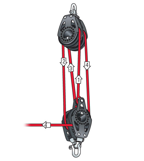
Sounds to me that pretty much like the modern way of rigging a mainsheet from the boom (your jib/foresail clew) to a traveller car running a track (your horse). The terminology is different, but here's one way of implementing this. The top block attaches to the jib clew, the bottom block attaches so as to run along the length of the horse, be it by shackles, thimbles, dead-eyes, etc.. This system is single ended and has a becket on the bottom block where the sheet begins; it reeves up, down, up, down, turn-and-out. It is easily adaptable to a double ended system by striking the becket and adding a third sheave to the bottom block. In the double ended system, you enter from 'port' and turn and go up, then down, then up, then down and turn and exit to 'starboard'. Double ended systems are a witch, because you have to worry about sheet tail lengths on both boards and keep them both secured so the sail doesn't blow the slack weather tail out of the block. I don't know how blocks were physically attached to something like a horse back then. This was the province of the bosun. I've known enough bosuns (modern equivalent) to recognize the first thing they do with their new boat (toy) is re-rig everything they can to suit their preference and proclivities. Heck, I'm as guilty of that as any crew chief. So there is a smorgasbord of period attachment fiddly-bits, any of which would be appropriate for the function given the required geometries. Just MHO. John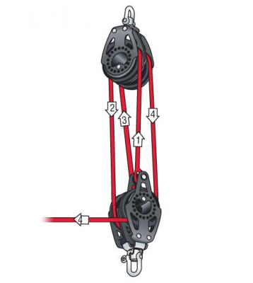
-
Johan, your work is exquisite, and your choice of music for your video is perfekt. Boccerini's Op 30, No 6 was for a string quartet. The Master & Commander people did it up as a serious duet, violin and cello. Incredible trnscription. J
-
Frégate d'18 par Sané , la Cornélie
JohnE replied to JohnE's topic in CAD and 3D Modelling/Drafting Plans with Software
I may just give the final draught set a ‘bogus’ waterline. Review of the Cornélie Devis and the sailing trials of Citoyen Villemaurin, Capitaine de Vaisseau, shows 5 different waterlines (tirants d’deu) under 5 different load conditions. First isTirant d’eau du batiment absolument: basically push her off the stocks and see how the hull floats. Next is Tirant d’eau ayant des bas mats; basically the hull with “stuff” including the lower masts. Next is something having to do with fully rigged and ballasted and perhaps armed – this page curves into the center of the volume and the text is indecipherable from the image. Next is a similar entry, but one can distinguish “moins deux, moins de biscuit”. This is the first entry that records height of battery. So I presume this is the full-boggie ship awaiting men, water, wine, and stores. Last is Tirant d’eau en charge: fully loaded, good-to-go. Notably, the Tirant d’eau en charge exhibits a height of battery of 6pi, 2po, 4li. Sané puts the battery height at 6pi, 2po, in the Reglement Devis; 1/3 of an inch, not bad. Yes, looks like all of this is empirical. It also looks like French frigates (Sané frigates) trimmed down a bit at the head. There was drag, but only half what you would expect. The documents have pages of blank entries. These were from Plan 1 to 5 of Villemaurin’s tests.Villemaurin’s journals are lost to us. His entries were never transcribed into the Devis document for Cornélie. We have lost much John -
Frégate d'18 par Sané , la Cornélie
JohnE replied to JohnE's topic in CAD and 3D Modelling/Drafting Plans with Software
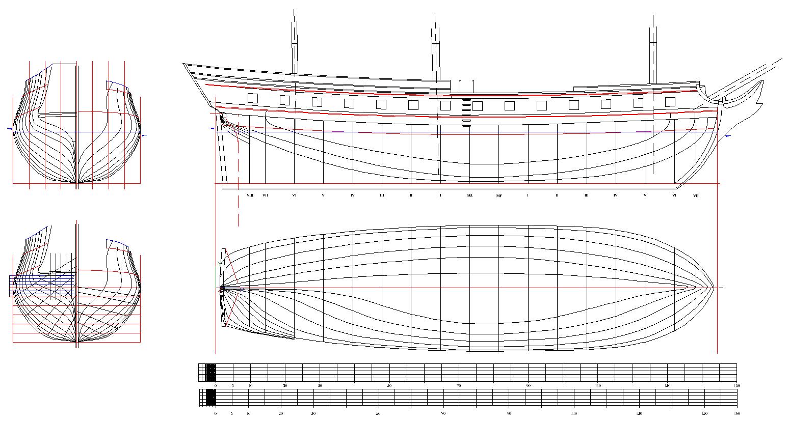
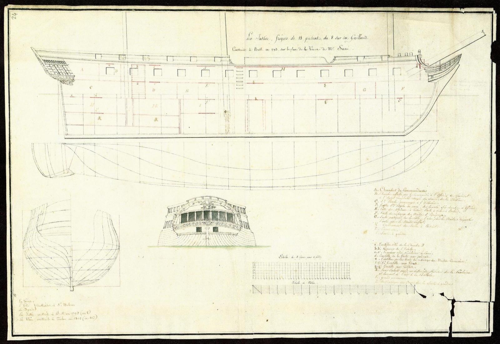
You guys crack me up. That's beautiful Bava. I especially like the wine stains, makes me feel right at home. Could have been that night when me and the Admiral were getting frisky with some new Beaujolais. Thanks for doing that. I'm going to print and frame it. Thought I would post the Rochefort plan, since I talk about it enough. Comparing the plans shows some of the anomalies I've been having to deal with. Rochefort shows her pierced 13. But the Virginie class was pierced 14 (viz, NMM plan of Virginie) as well as Boudriot's Venus. I pierced Cornélie 14 and positioned the sabords according to Sané's Devis. They follow along well and the 14th plopped right into the blank space in the Chambre du Commandant; so move the bed, Dude. The head and bow profile of the Rochefort Justice is ugly as sin; short, high, choppy, truncated, mumph. The Virginie plan shows a much different bow profile and one that is reminiscent of the Venus. The Pallas class Eregon plan has a similar elegant bow profile. Even the Armide exhibits that elongated elegance. So I followed Sané's rake and curvature rules from the gabarit d'etrave of the Devis and stuck a Virginie/Eregon proue on it. Topside details are also very much a hybrid. Mine are a mix of Justice, Venus, Eregon and Vial du Clairbois, Pl 2. There's lots more detail in the white paper that accompanies the basic plan set, about the ship and the whys and wherefores of her provenance and the departures therefrom. Guess it really is a frégate de 28 Canons de 18 en Batterie, par Johné after all. Thank you all, and Ciao. John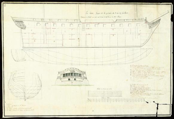
-
Frégate d'18 par Sané , la Cornélie
JohnE replied to JohnE's topic in CAD and 3D Modelling/Drafting Plans with Software
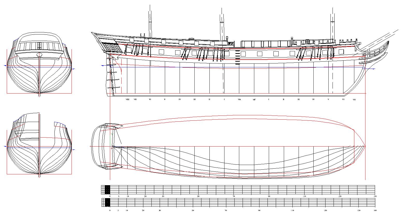
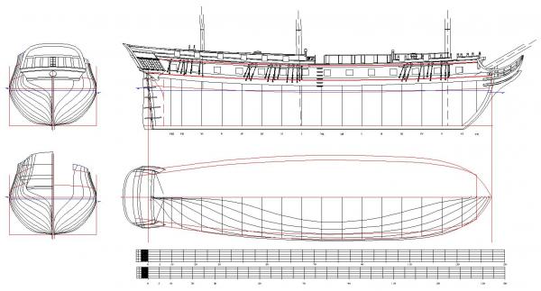
Bit more marginal progress on the profile. Added some moulding to the rails and the quarter galleries, for CaptArmstrong. It's a bit crude but he's right, it does add a skoosh of pizzaz. Showing a peek of the cabestan on the QD. I'll have that full-view on the internal profile plan. Also saw that Vial has stanchions bracketing the entry port, so I put some in there as well. Thing this plan view is getting to the diminishing returns stage, so off to the internal detail profile. Need to have something suitably close to complete for when Bava wants to do a 3D of her. Still no carving art, but have recieved an offer of assistance that can't be refused. I think she's going to be a beauty. J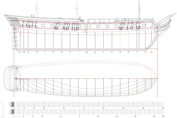
-
Great show, Bava. Wish you could do that for Cornelie. J
-
Frégate d'18 par Sané , la Cornélie
JohnE replied to JohnE's topic in CAD and 3D Modelling/Drafting Plans with Software
Thanks to everyone for your kind comments. I have only been in the modelling world for a couple, three, years, so some of my things might seem a bit rough around the edges. I am very appreciative of the interest and assistance I have received from people on the NRG forum. You folks are the tops. Just for grins, I thought it appropriate to show the source for my take on the Renommee. Having these documents is valuable, but the really cool part is reading through them and getting to the end and, ... there it is ... signé Sané. Can't imagine a bigger thrill for an amateur historian. ps. my photos of documents in SH321 and SH 325 with the kind permission of .le Service historique de la Défense. John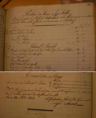
-
Frégate d'18 par Sané , la Cornélie
JohnE replied to JohnE's topic in CAD and 3D Modelling/Drafting Plans with Software
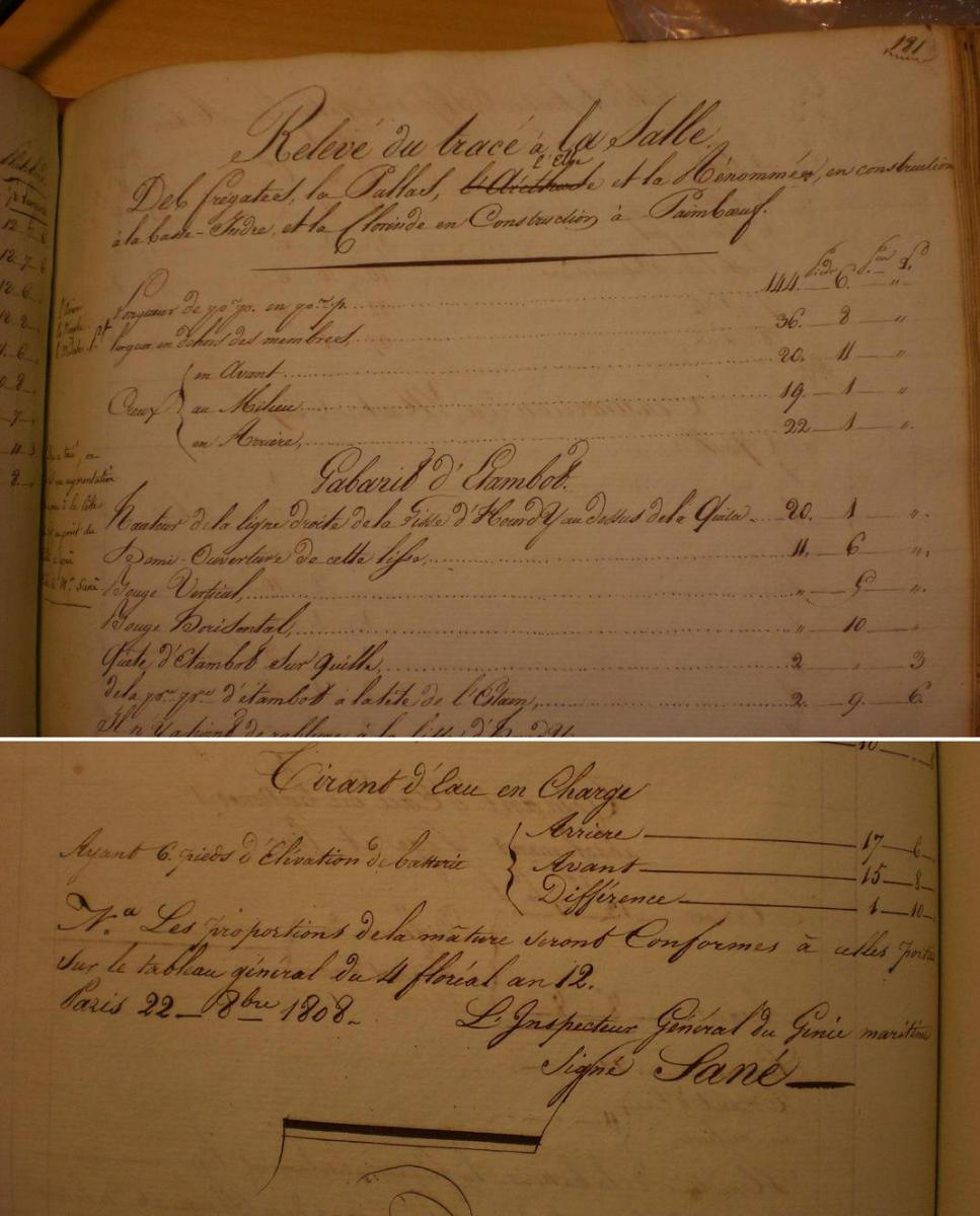
For uss frolick. I was doing some double checking of values and was looking through the devis of the Pallas, when right at the top of page 181 was the heading, in Sane’s handwriting: Releve du trace a la Salle des fregates la Pallas, l’Arethuse, et la Renommee, en construction a la basse-Indre, et la Clorinde en Construction a Paimboeuf. [l’Arethuse was lined-through and l’Elbe annotated above it] There are marginal notes, written by Sane, that specifically refer to Renommee (and Pallas, Elbe, Clorinde) and some minor departures made therefrom by the next series of Nantes vessels; Ariane, Nymphe, Meduse (1810 launches). On pages 184 and 185, there are sections entitled “Acastillage [sic] de la Proue” and “Acastillage de la Poupe”. I am confident she had a beakhead bulkhead. The bow timbers topped off at the standard location approximately 3pi 6po above the level of the main (gun) deck. Station VII (beakhead) timbers extend to the nominal drift. A beakhead bulkhead is strongly indicated. As to her transom, the Pallas class was “straightened-up”. Hard to say when this happened; maybe somewhere in the Hortense class, or perhaps with the ‘Reglement’ in the Pallas class. Earlier designs (Hebe/Venus and Virginie) had an elegant 30 degree rake to the transom. Hortense is indeterminate. Pallas had a 20 degree rake. The same things happened with steeve, sheer, and tumblehome. Stern timbering was identical to earlier vessels except for the degree of vertical rake. From all this, I am inclined to view the Renommee model as somewhat “fanciful” in its details. Pallas, Elbe, Renommee were the lead ships of the ‘Reglement’ and were built side-by-side, at basse-Indre, and launched within 3 months of one another. They were closely monitored (viz, Sane’s notes on comparison with the next launched ships), so there would not be any opportunity for changes, at least not without major annotations to the Releve. I submit that Renommee was a typical Sane frigate when she was captured and taken into British service as Java. Humbly submitted. John -
Frégate d'18 par Sané , la Cornélie
JohnE replied to JohnE's topic in CAD and 3D Modelling/Drafting Plans with Software
No, druxey, I didn't. I just checked again and there's nothing in the inbox. J -
Frégate d'18 par Sané , la Cornélie
JohnE replied to JohnE's topic in CAD and 3D Modelling/Drafting Plans with Software
Okay. Got it, CaptArmstrong. Yes, I can do that. Justice and Cornélie were both originaly built Virginie class ships, from the same yard that did Virginie (Brest). I have the NMM plans of Virginie that include much of that detail. Very similar to Boudriot's Venus, but a 10 years later class and so with particular detail differences, but substantially much of a muchness. I can use both references to advantage. Thank you. John