JohnE
-
Posts
309 -
Joined
-
Last visited
Content Type
Profiles
Forums
Gallery
Events
Everything posted by JohnE
-

Frégate d'18 par Sané , la Cornélie
JohnE replied to JohnE's topic in CAD and 3D Modelling/Drafting Plans with Software
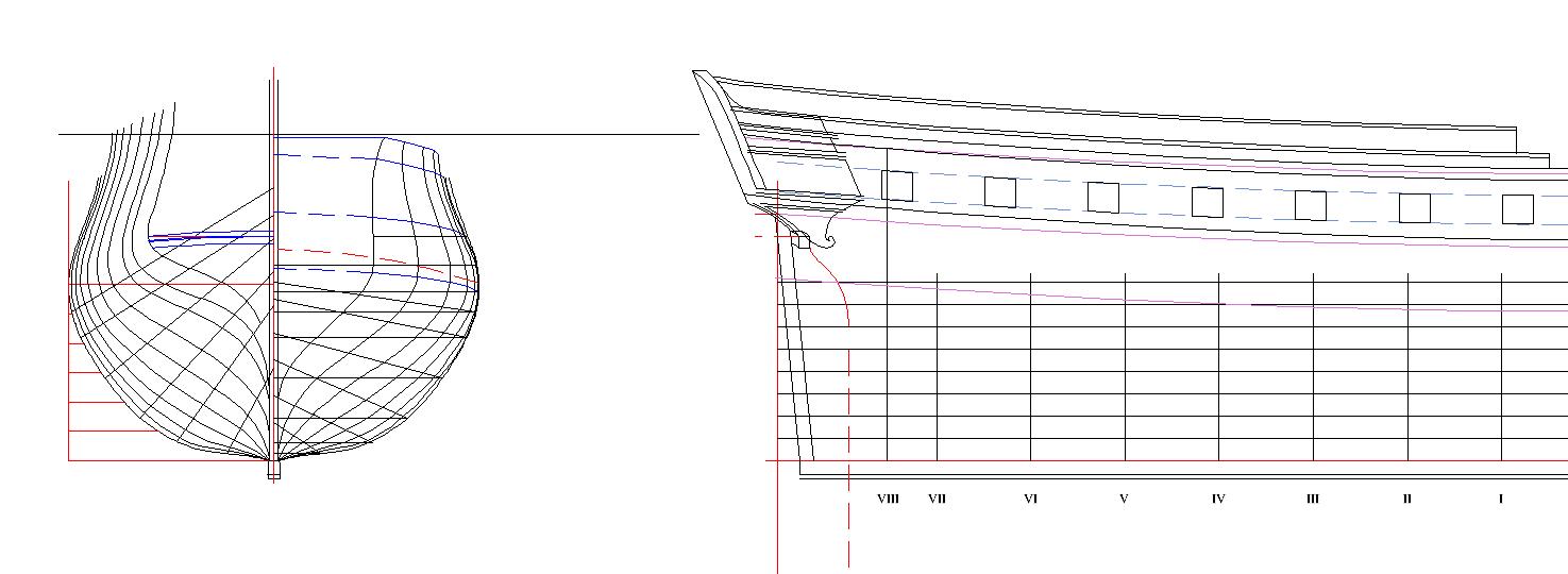
I've heard that one, but there's no one to blame but myself for this one, druxey. Ok, so do it right. Transom buttocks finished. Every point sits in the assigned spot in 3-space. All 3 orthogonal axes are satisfied. Buttocks are smooth, fair, and well rounded, just like ... um ... er ... you know. Shape and form is the elegant everything. Cannot imagine the French doing things in any other way. Ok, so the lines are a wrap. Now off to do pretty fiddly bits on the profile plan and make her look like the proud frigate that she was. More to come. John
-
Frégate d'18 par Sané , la Cornélie
JohnE replied to JohnE's topic in CAD and 3D Modelling/Drafting Plans with Software
Whoah. Do it right and look what you get. Think before you click should be written on the inside of my eyeballs. [attachment=280245:Transom Waterlines.jpg]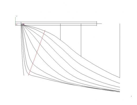
-
Frégate d'18 par Sané , la Cornélie
JohnE replied to JohnE's topic in CAD and 3D Modelling/Drafting Plans with Software
Well, every blivet is a learning experience. I'm sure Mark would agree with me on that one. I'm thankful I'm only trashing electrons and not wood; that would be a real bummer. Found out what I did; actually didn't do. Some things are easy in Corel, but counter intuitive in TC. Likewise, there's things you can do in TC that you can't do in Corel (at least not very well). Only real solution is to do some things in one, and some things in the other. Live and learn. Always measure twice before you tweak, and then measure again to make sure you tweaked it right. John -
Reading Boat Drawings
JohnE replied to Julie Mo's topic in CAD and 3D Modelling/Drafting Plans with Software
Hi Julie. I think FreeShip looks at body stuff. Keels are appendages. Ciao, John -
Frégate d'18 par Sané , la Cornélie
JohnE replied to JohnE's topic in CAD and 3D Modelling/Drafting Plans with Software
Oh, Lord. Thought I was a happy camper, but found some nastiness in the CAD program paradigm. Seems that rotation does not apply to a uniform "square" object space, but rather some rectilinear space that morphs/modifies in both x and y when rotation is performed. I have built a 'y' model of a series of 'waterlines' and then rotated it through 20 degrees. The length of the line connecting the dots, when upright, is 7.00 inches. When rotated through 20 degrees, the same line is 7.97 inches. The damn program doesn't even follow the sine rule. Gonna pull down the inset waterlines and calculate them again with Corel. Sometimes you gotta love CAD programs, sometimes you gotta hate them. Thing is, they never tell you what they are doing internally. You just have to try, and cut, and fit, and find out it's all blithering nonsense. Woof !! Ok, off to 1:1 printing and a pair of Staedtler dividers. John -
Reading Boat Drawings
JohnE replied to Julie Mo's topic in CAD and 3D Modelling/Drafting Plans with Software
Hi Julie. I'm doing much the same thing on a different model. I'm going towards wood and not 3-D, but same, same. Can help. Shoot me a pm. I routinely use Corel and TurboCAD, but AutoCAD is a no-brainer. John -
Frégate d'18 par Sané , la Cornélie
JohnE replied to JohnE's topic in CAD and 3D Modelling/Drafting Plans with Software
Ok, buttock bow lines. Sweet. They begin and terminate at the intersection point with the first (top) waterline in the body plan. Buttock lines in way of the transoms will be on an inset that goes from the lisse d'hourdy (wing transom), through the filling transoms and extending to Station VII aft (like in the waterline inset). I take back everything I said about the French being more concerned about the "perfect solid" bow and dismissing the stern. I was wrong. Mea culpa, mea culpa, mea maxima culpa. If you read Howard Chapelle carefully, he makes note of the "straightness" of the mid-line buttock as it crosses the waterline, as an indication of "potential" speed. I note that Sane's buttock lines are quite relaxed (a very good thing) and the mid-line is pretty straight as it crosses the design LWL (a very, very good thing). Looking at these with a jaundiced racing sailboat designer's eye, I am pretty impressed. When you take the run of the lines back through the transoms, it's pretty clear that there's some high velocity curvature going on above the waterline mark. If you think Chapelle, it makes a lot of sense that French ships were very sweet and quick, when loaded to the design LWL. It also makes a lot of sense why they were 'dogs' when over-loaded to typical RN standards. Boy, oh boy, this is so much fun! John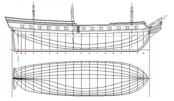
-
Hi Mark. My thoughts and prayers for Janet. French planking is a system unto itself. It has ‘rules’. Often these are honored in the breach in many cases, and they change once one gets into a ‘ship’, as opposed to a ‘frigate’ or ‘corvette’. Drawings by modelers are very nice, but often don’t capture the essence of le système de bordages. This is not a criticism, because you are far beyond that. It’s just an observation for, perhaps, “next time”. The French counted strakes from the garboard to the wale. They had a rule for ‘thinning’. In my model of a frigate, it’s about 30+ strakes, top to bottom, and thinning is from 30 to about 22. Wales are thick and 12” on the profile. There may be a second ‘wale’ strake below the first, having a ‘thick’ strake there between. The ‘thick’ strake might be 12” or 8” (yard dog choice, but mostly wale size). Below the bottom ‘wale’ strake, each successive plank is shaved down, on the bottom, by ¼ pouce, until it gets to the nominal hull plank thickness (hopefully in region of the nominal hull strake). That’s how the French did it. This is just a fyi kinda thing. Don’t expect you will be tweaking and wouldn’t want you to. We’re talking scale millimeters here and it just don’t matter. John
-
Frégate d'18 par Sané , la Cornélie
JohnE replied to JohnE's topic in CAD and 3D Modelling/Drafting Plans with Software
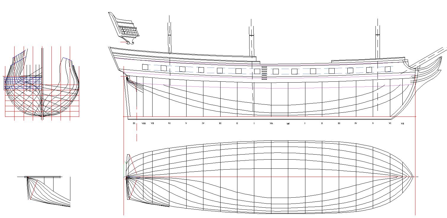
I wish to thank everyone for the 'likes' and comments. More progress. Mr handy-dandy Fashion Aide has been doing a wonderful job. Added 5 additional closely spaced (1 pied intervals) waterlines, in way of the transoms, to the half-breadth as an inset. Did several sanity checks on the results, and they pass muster (don't drool, eat flies, or howl at the moon). This should help lofting the stern. Everything is in place for a set of buttock lines, and the good old Mk-1 eyeball doesn't see any obvious glitches. So buttock lines on the profile plan; lines of decks on the half-breadth plan; and detail finish work on the profile view; chains, bitts/bollards, head, etc. and maybe I can put the basic lines plan into the can. Lots of labeling and scaling to do, but that's fun fiddly bits. Can't wait to get there. John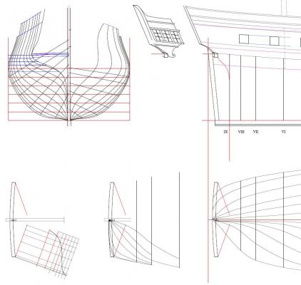
-
Frégate d'18 par Sané , la Cornélie
JohnE replied to JohnE's topic in CAD and 3D Modelling/Drafting Plans with Software
Whoah, Idaho Crackers. Is that anything like Montana Chips? You seem to be right down the road from my favorite ski place in the US in Ketchum. It's probably good to be you, at least in ski season. Not a genius, just an anal retentive plodder. Lots of other modelers do much the same for their favorites. As for the lines plans, the idea is to talk with a few people and use their input to get them into shape for publication and then give them to NRG to do with as they wish. I can hope for NRG making the files available, perhaps free to members, perhaps charging a nominal fee to others, whatever, but just getting the design plans out there is my fondest wish. John -
Frégate d'18 par Sané , la Cornélie
JohnE replied to JohnE's topic in CAD and 3D Modelling/Drafting Plans with Software
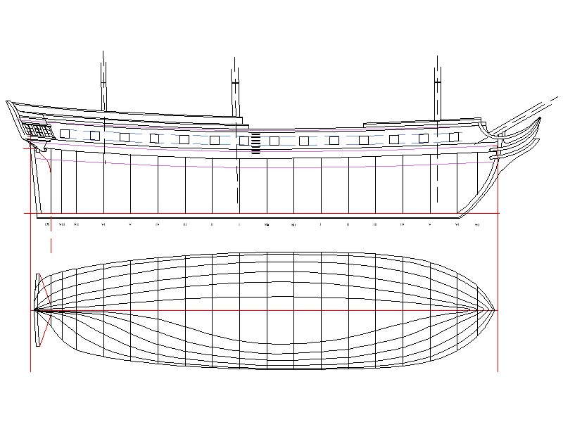
Hello, Idaho. That’s basically the plan (pun, arr, arr, arr). There aren’t any modeling plans for an Empire period Sané firgate, so I decided to make a set. It involved basically designing a vessel from first principles, using Sané’s notebooks and instructions, and a set of period treatises used as how-to manuals by the shipwrights. The thread is about CAD being an invaluable tool for getting all the arcs, curves, angles, dimensions, and projections smooth and self-consistent in all 3 views; sufficient for a building plan of the vessel. Gotta have a good lines plan, or else nothing else will fit. CAD is also good for scaling. I draw/construct at 1” = 1’ and use French feet (pieds, pouces, lignes) as the dimensionality metric because that’s what the period documents use. Once finished, it’s simply a matter of scaling up by 1.06575 to get to English feet and then scaling down to 1 : 36 or 1 : 48 to produce a useable set of plans. Those should be ready fairly soon. Once the lines plans are finished, it’s off to specifying the pieces of wood: keel/bow/stern, disposition of frame, internal hull fixtures, deck plans, cabestans, brioche ovens, wine cooler dispensers, and the like; almost everything one would need. John -
Frégate d'18 par Sané , la Cornélie
JohnE replied to JohnE's topic in CAD and 3D Modelling/Drafting Plans with Software
A prochain indeed, Mr Druxey. Lots of progress. Woof ! Starting to look like a French frigate ! Did the masts. Different from Boudriot's paradigm. He took the heel and went vertical. The Rochefort draught had the same heel position but raked the main and mizzen. so wtfo? Went to Villemaurin's reports on Cornélie and did a judicious tweak on his "sweet-spot" and the next-most upright rake angle. It's a bit less than what's shown in the Rochefort draught, but somewhat more than what Boudriot denotes. The lines look good. There may be a few small tweaks here and there, but the plots are internally self consistent and follow the nominal of several period draughts from 1797 to 1809. I'm a happy camper. John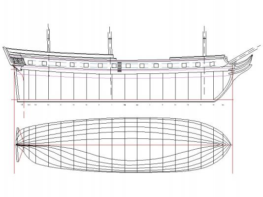
-
Frégate d'18 par Sané , la Cornélie
JohnE replied to JohnE's topic in CAD and 3D Modelling/Drafting Plans with Software
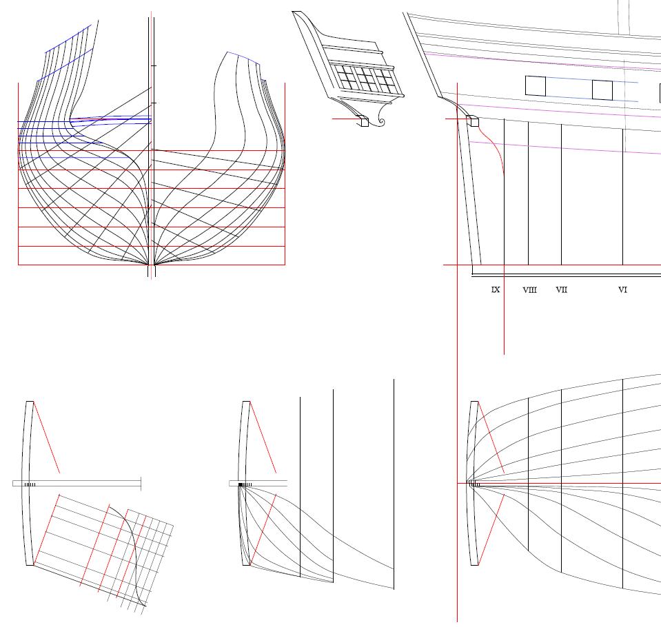
Druxey, Je vous remercie infiniment. I have this suspicion that they are laughing with me instead of at me. Yes, my French is atrocious, and yes the French are a bit arrogant. They believe if one can’t speak French, one simply isn’t civilized. But they do give a lot of points for effort. Ok, so body plan. I think the lines are exquisite. They fair perfectly on waterlines and diagonals. Next is the half-breadth, with the inset for the transoms. Beginning to be a very happy camper.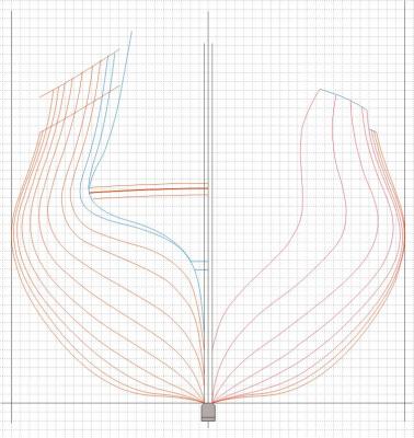
-
Frégate d'18 par Sané , la Cornélie
JohnE replied to JohnE's topic in CAD and 3D Modelling/Drafting Plans with Software
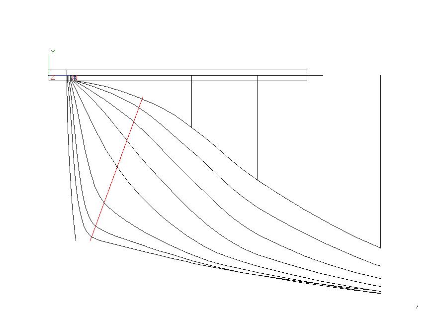
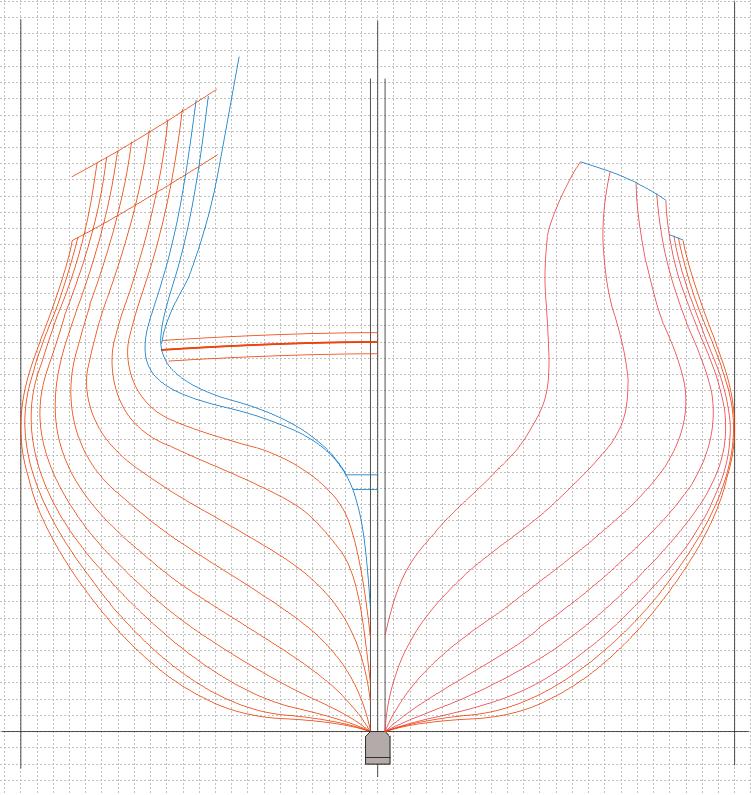
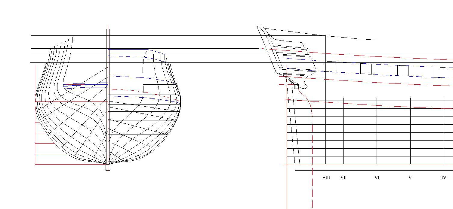
Following the rules, things are looking much better. The blue lines are the fashion profile and the profile of my bogus station IX. Station IX is only there to help adjust the waterlines where curvature gets complex. It is the last square couple in the ship. The heel of the fashion frame sits atop its after half-portion, so the lines necessarily converge. Below (abaft) the convergence is the line of the ‘massif’ (deadwood) fairing to the keel and stern post. Station IX is not ‘official’. It is user defined. Knowing frame spacing and the location of the heel of the fashion frame on the profile plan defines a location for “Station IX” in my set of drawings. Clearly, other designs will differ, but I think it a valid positional reference for a Sané designed frégate d’18. Yes, Druxey, station IX is a projection off my handy dandy Fashion Aide. I doubt I could use it for psychological projection … I’d be in a white jacket in a rubber room faster than you could say “buttock line” . When I talk to my friends in France I always apologize for mon atroce français. After reading a lot of period works, my French is getting much better but it’s français ancienne, and still atroce, so my poor friends are so confused. John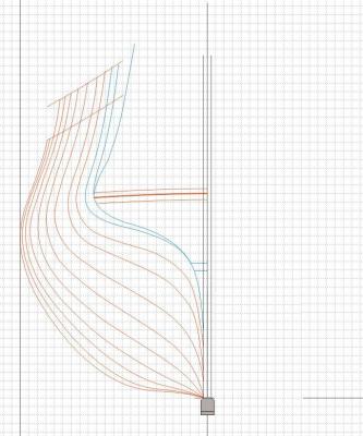
-
Frégate d'18 par Sané , la Cornélie
JohnE replied to JohnE's topic in CAD and 3D Modelling/Drafting Plans with Software
Thanks Druxey. Thirst lurks in madness. Want water, go to the well. Plowed through Vial du Clairbois and followed the bloody instructions this time. Made a little graph thingy I call the Fashion Aide. Looked a little familiar and lo-and-behold ! wouldn’t you know it, Boudriot read Vial too and put a similar figure from Vial into his book on the 74. It’s a great tool. You can develop waterlines in way of the transoms, buttock lines, tweak them back and forth till they look like what you want and then do the projection to get a profile of the fashion piece that will give you those lines. You can start at any of the three; FF profile, waterlines, or buttock lines. When you are finished, you can simply project in space and get the outside profiles of all the filling transoms, as well as their evolving bevels along their lengths. All in one simple graphical representation. They sure weren’t stupid in 1787. Woof !!!! Apparently the shipwrights read Vial too. It rarely appears in French draughts, presumably because it’s something everybody “knows”, but there’s a draught of a Pallas class Sané frigate, built at Antwerp, that has an inset to the half-breadth that shows the additional set of waterlines in way of the transoms. Since the Dutch/Belgian yard-dogs grew up in a slightly different school, perhaps they needed that extra ounce of assistance. Anyway, proof positive that the method was used and it worked. Right then, back in the boat and sailing in the right direction (hopefully). Good old CAD plots; set the scale, know and love your base coordinates, and just zoom in and read the offsets. Back to work. John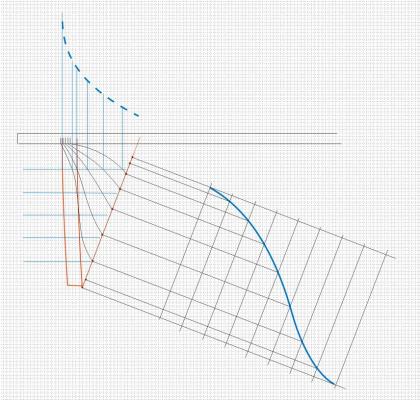
-
Frégate d'18 par Sané , la Cornélie
JohnE replied to JohnE's topic in CAD and 3D Modelling/Drafting Plans with Software
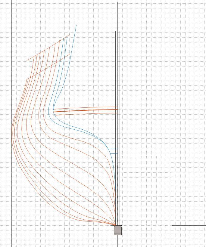
Making progress, but it’s retrograde. Trying to get efficient in lofting the stern, so added station IX, a la Boudriot. Didn’t work out and gave some really squirrely lines at the diagonals. Also pulled the breadth curves outward, somewhat for stations VII and VIII. Don’t know what Boudriot used as a gauge for station IX. There is a kinda/sorta vertical frame (the very last one), behind station VIII, but it’s disposed forward of the IX line. It is a frame and half-frame that sits right at the intersection of the bottom edge of the fashion piece. In fact, the fashion piece rests on the top of the after half-frame portion of the couple, so the ‘station’ and fashion lines should intersect at around the 5th waterline and the red dashed vertical line of the profile. Obviously, they don’t. More work needed, but have a couple of methods that should get me there. Ed Tosti writes in his book on Naiad, that the body and longitudinal lines need to be iteratively tweaked and adjusted in order to be self-consistent and fair. So, back to basics and do the lofting of the fashion piece and filling transoms in accord with with the rule. Then plot those lines. Then extend them to the station lines. Then take a slice and plot it as a ‘station’ as appropriate, and do horizontals through appropriate portions; all with simple explanations as to who, what, where, when, how, why, and who’s on first. The image is not utile. It represents what one does by following a paradigm that one does not quite understand. One must, simply must, hew to what one started with. .
-
Frégate d'18 par Sané , la Cornélie
JohnE replied to JohnE's topic in CAD and 3D Modelling/Drafting Plans with Software
I don't know if this is appropriate on the forum, if not I sincerely apologize. But since this is a French oriented thread, I simply had to say to all my French friends: Moi aussi je suis Paris. Moi aussi je suis Charlie. Dieu accordera le droit. Dans la tristesse et le plus grand respect. Dieu vous donne la paix en cette période troublée John [ed] redid this in the right thread. Thanks for the heads up Mark. -
Frégate d'18 par Sané , la Cornélie
JohnE replied to JohnE's topic in CAD and 3D Modelling/Drafting Plans with Software
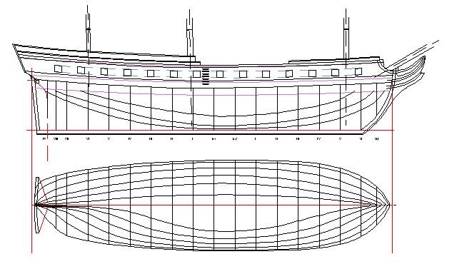
Thanks all for the likes and comments.No one was more surprised than I at the result. Here's a bit more progress; hung the top of the wales, and put in the sheer, waist, and the two quarterdeck, drift rails (did the forecastle drift, as well). Beginning to look like a ship, now. John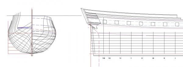
-
Frégate d'18 par Sané , la Cornélie
JohnE replied to JohnE's topic in CAD and 3D Modelling/Drafting Plans with Software
More progress. Working on the profile plan and have decks (red) and gunport lines (blue) pretty well done. Am working on the hanging of the wales and the profile of the quarterdeck rail. Got a good start. Added an outline of the stern detail to the profile plan. Angles and mulion placements are as per the specification and plans. Imagine my "war whopt, fist pumping air, God, I'm good, Antler Dance" when the decks and everything came together within a half inch (French). Yes I know, I have to tweak the tops of the lines in the body plan to be self consistent. Wayne Kempson reminded me how to do that. I owe him a lot. Happy days. John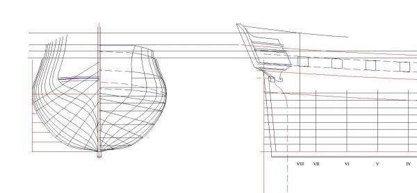
-
HMS Naiad 1797 by albert - FINISHED - 1/48
JohnE replied to albert's topic in - Build logs for subjects built 1751 - 1800
Indeed, Oh My ! You and your friend Aldo make beautiful things. John -
Oh, woof. I got a preview from my French friends and Jean-Claude Lemineur's plans and drawings are absolutely first rate. Yes, I am doing plans for an 1810 Sane frigate, but I need to work with some wood so that the plans make sense. L'Hermione is at the cusp and very clearly resembles the Revolutionary designs; more so than Le Belle Poule (sorry). I've looked at the plans and drawings, and think they will work wonders for my eventual project. Once I get the volume, I will be opening a Build Log and seriously disturbing my dog Beaudy's calm with whining saws and sprays of sawdust. John
-
Oh, Faith, Begorrah, and all the Saints in Heaven; I am sooo all over this. Ordered it. Herminoe was designed by Pierre-Henri Chevillard and constructed under the supervision of his cousin Jean-Denis Chevillard, who became Ingénieur-Constructeur en Chef at the Rochefort Dockyard a few years later in 1781. They did the Charmante 32 and Concorde 32 Classes of frigates, as well as several 74s. The Chevillards are rather neglected, but their contributions to French ship design and shipbuilding techniques, while incremental, are as innovative and interesting as those of Guignace, Coulomb, Duhamel, Forfait and Sané (in my humble opinion). This was the time of great change and evolution from early 18th century practice. Many of the new features were incorporated into the Revolutionary and Empire period ships. This was an exciting time ! Mike, Mark, if you are interested in French period ships (frigates mostly) this is a “must have” book. Imagine your historical bookshelf with empty periods. I am so glad that Editions Ancre have gone beyond Mr Boudriot’s death. Jean-Claude Lemineur is a worthy sucessor. I love his take on accuracy vs practicality. A man after my own heart. This is going to be a serious build monograph. Just saying. John
-
Frégate d'18 par Sané , la Cornélie
JohnE replied to JohnE's topic in CAD and 3D Modelling/Drafting Plans with Software
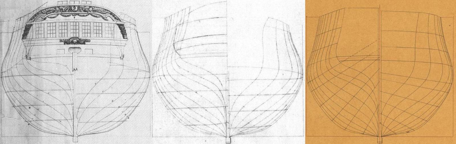
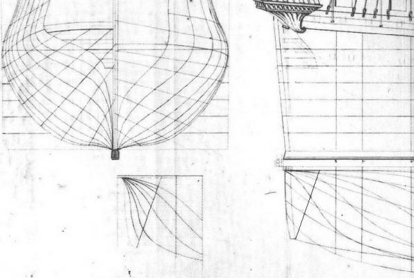
Whoah, now this is cool.! On the left is the body plan for La Virginie, taken by Portsmouth Dockyard soon after her capture in 1795 (signed by John Marshall, dated 1796). The center image is from the Rochefort plan of La Justice (looking more and more as the poster plan for Sane’s 1810 Reglement). The right side is Armide, laid down 1813 and finally launched in 1821 at Toulon. Some really serious comparisons are in order, here. Justice and Armide body plans aren’t far off. When compared to Virginie, one can see the aft frames, after station 7 taking a more relaxed aspect. Woof !! drafting lines to ‘plans’ is an exercise in frustration.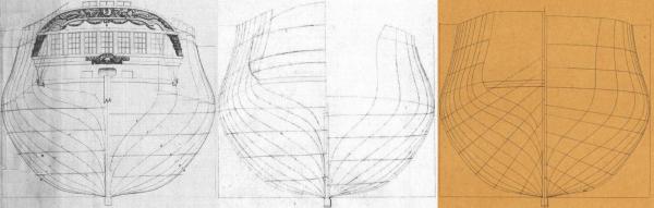
-
Frégate d'18 par Sané , la Cornélie
JohnE replied to JohnE's topic in CAD and 3D Modelling/Drafting Plans with Software
Darn. Drafting your own plans is a bit like working with the wood. The plans have to conform to the wood, so one has to leap a year or two into the future and visualize the finished piece of wood in order that the plans make sense, practically and not just theoretically; model ship builders want to build a ship, not design it. Back in the period, yards would lay the keel, the stem, stern post, and perhaps the maître couples and a few others so they could set the ribbands and such, but the true birth of the vessel was the erection of the stern. Ed Tosti calls this the most complex/troublesome but most fundamental structure of a ship. He isn’t kidding. The stern “space” is defined by three, or more, unintuitive lines in contemporary French plans. A few designers drafted buttock lines, but most did not. They relied on the shipwrights using historical, contextual, experience, as expressed in the many treatises and text books of the period. The problem for this portion of the project is in drafting/extracting/reproducing an accurate set of buttock lines such that they might be combined with the other “aspect” lines of a draft and get a good, accurate, outline (with bevels) of the stern pieces – fashion frames, filling transoms, and the like. If I can do this to my satisfaction, I will be very pleased. Don’t think there’s anything else that will present such a big speed-bump (except for the pretty, artistic, carving stuff), so this will be my total captivation for a while. John -
AUTOCAD 18 DELUXE
JohnE replied to yamsterman's topic in CAD and 3D Modelling/Drafting Plans with Software
Hello Mick. What everyone else says. But TurboCAD is a good choice if you have the desire to truly go forward. As a program, it has many layers of difficulty, like an onion. I know many people, like myself, who have started using it in its simplist form and who have gone on to its deeper and darker aspects. I use it as a tool to do drawings for patent applications; brainless, I know, but a good basic tool. But the point is it has the ability to go from grade-school to grad-school. My sister uses it to design piping runs for nuclear submarines for Electric Boat. She uses it to get it right and then ports it over to the oh so ancient, but oh so classified, 4 generations ago Navy design program. So it can be a serious professional application, too. Just don't dive in too far on the first pass. Patience, patience, patience. A program will not do "it" for you, unless you are already familiar with the paradigm and simply want validation. Garbage-in, garbage-out, is a hard and fast rule. So just relax, and open the book at page 1. It will take a bit of time, but if you are righteous, all will be revealed, in time. I'm a TurboCAD user for these sorts of applications. If you have questions, shoot me a note. I'll help best I can. John