Sheerline
-
Posts
92 -
Joined
-
Last visited
Content Type
Profiles
Forums
Gallery
Events
Everything posted by Sheerline
-
Good point - well presented! I shall make good the missing keel wood parallel with the rabbet and start over. The tapered stern post will be retro fitted after second planking. Thank you for your input, most helpful. This resource is amazing
-
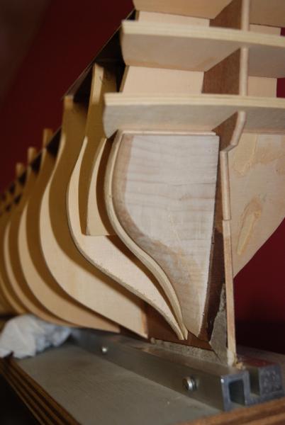
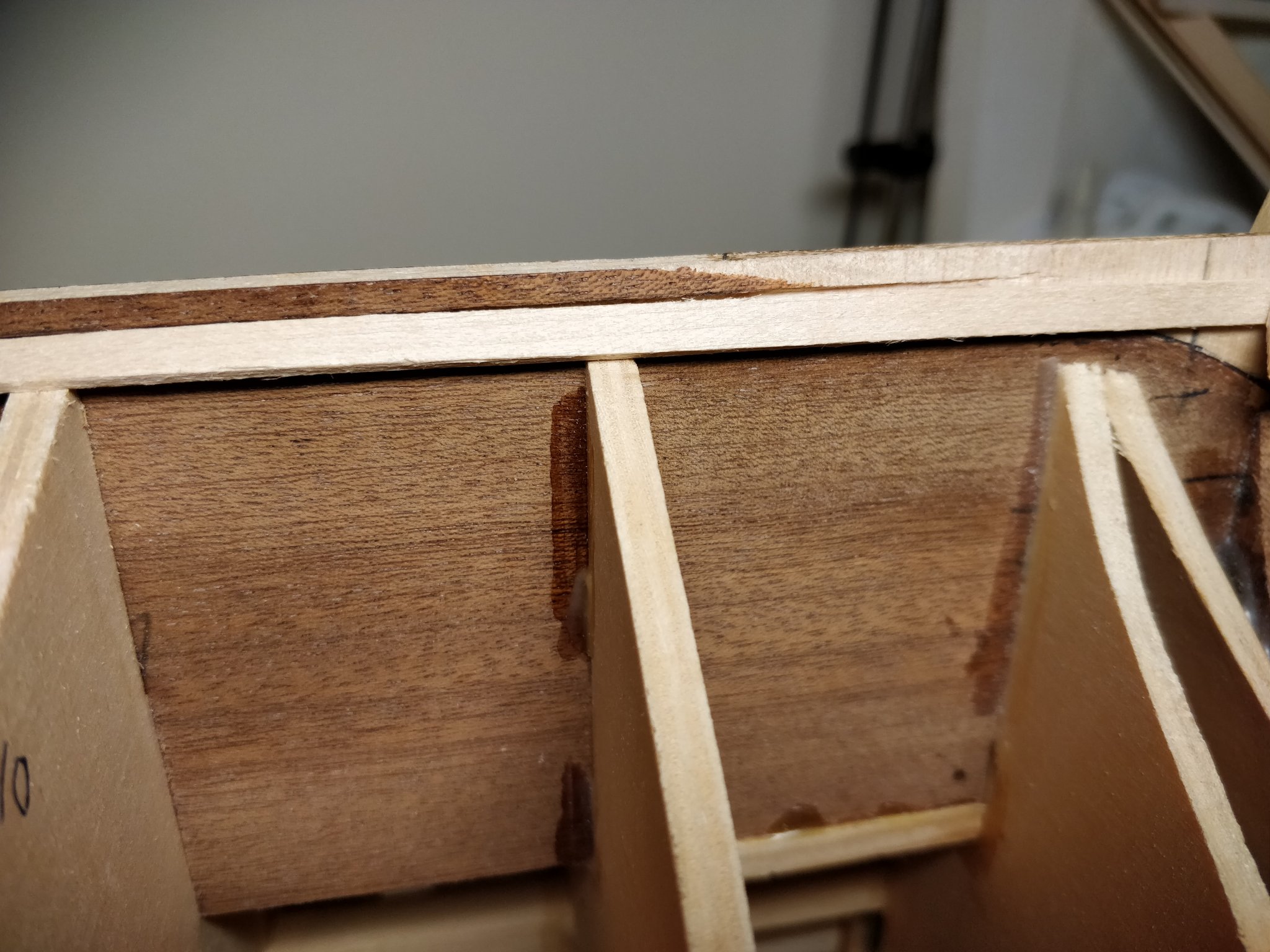
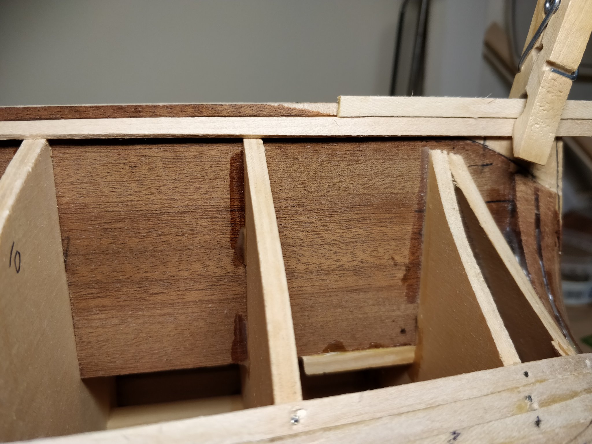
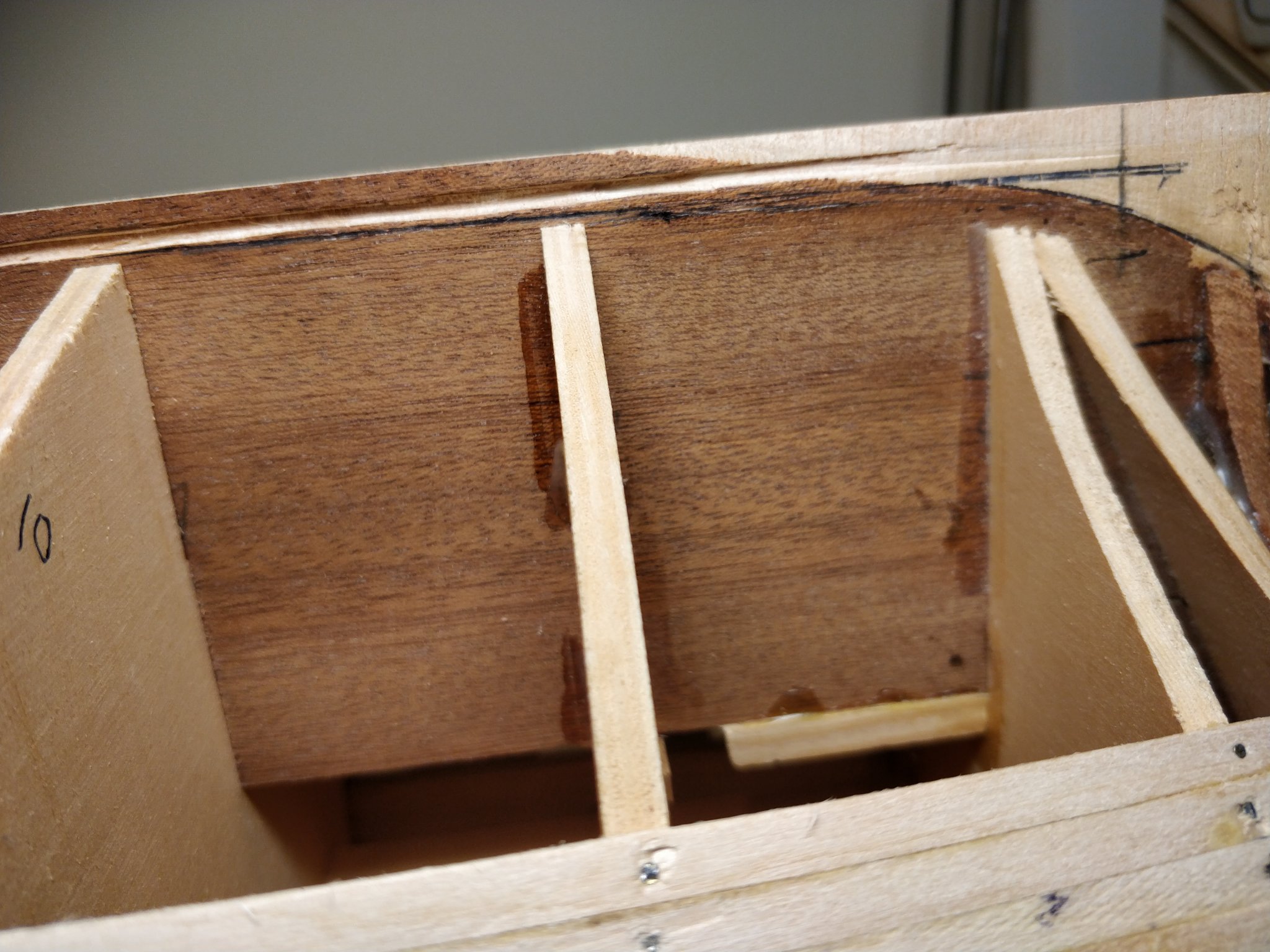
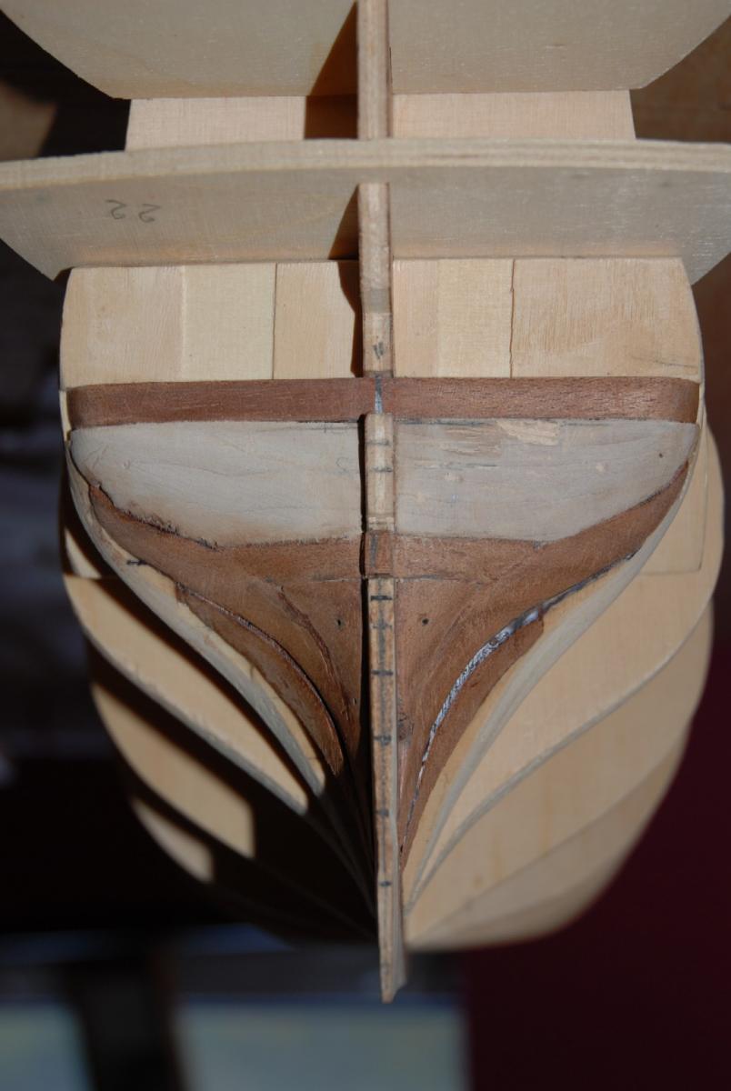
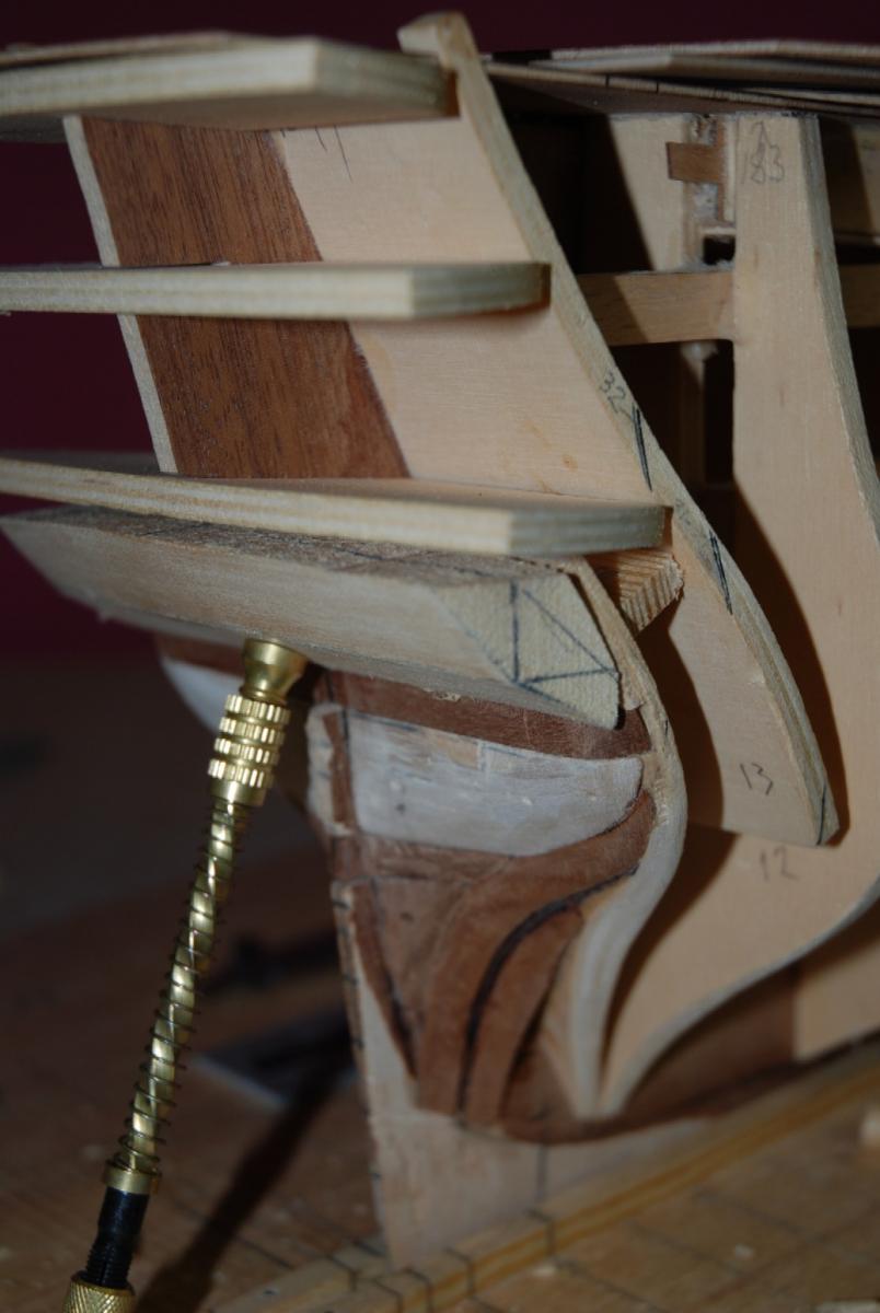
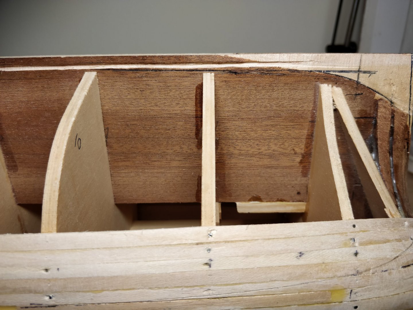
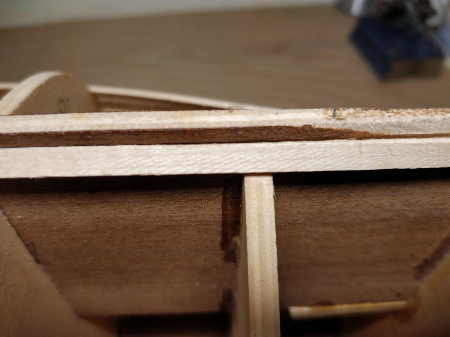
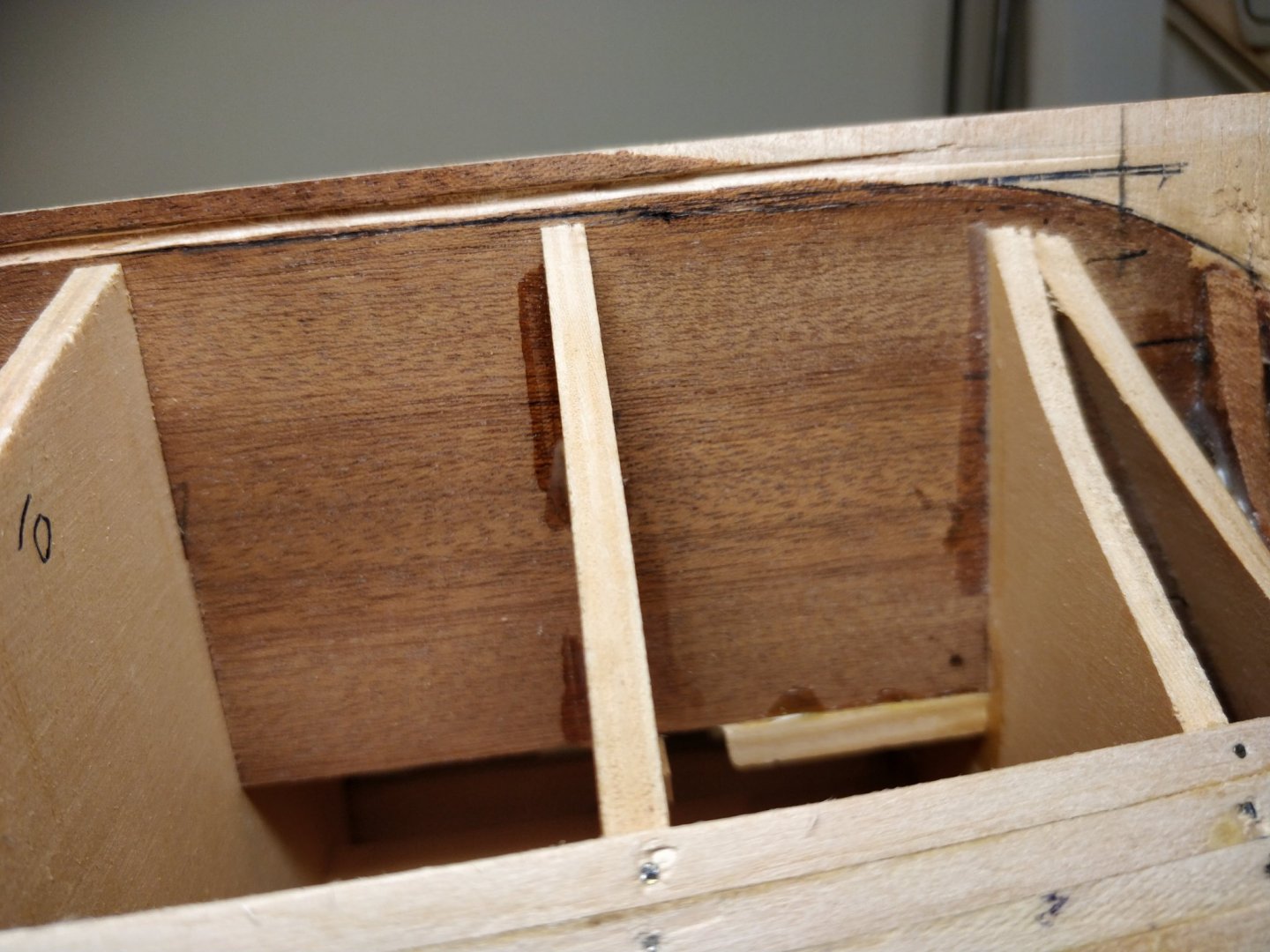
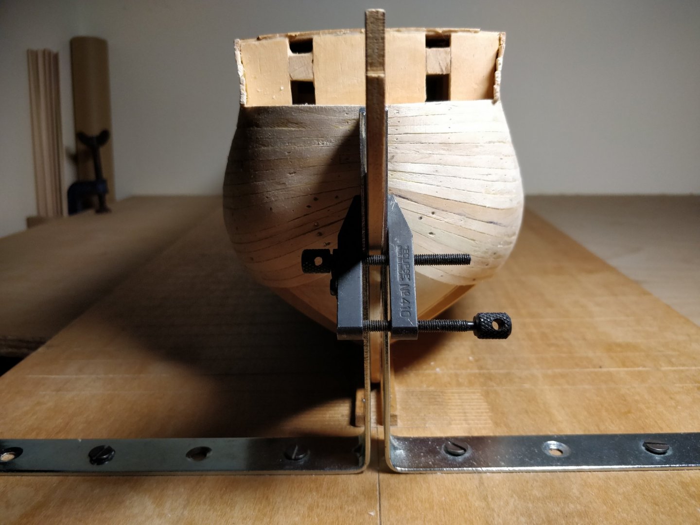
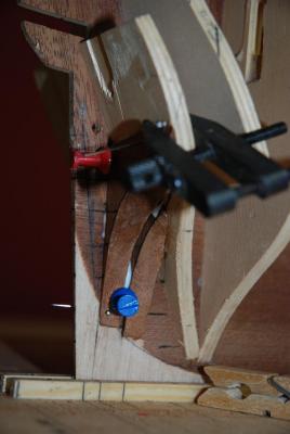
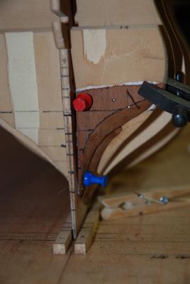
This was done deliberately and the stern post removed as seen in some texts. When the 2mm planks are on both sides and fettled it will return to 5mm thickness. Then the idea was to restablish the rabbet to take the very thin second planking. My concern really is the rate of rise in the 'deadwood' area and what kind of sweep or angle of climb it should have moving aft. My choices seem to be either to put packers on frames 10 and 11 or fettle a bit more off the rabbet to allow the plank to sit flatter?
-
Hi everyone! I need a few pointers to fit the garboard strake the correct way with the right degree of 'washout' . I've read most sources on the practical method but have possibly made a blunder when cutting the rabbit line between frames 10 and 11 aft. The bottoms of these frame don't coincide exactly with the rabbet and I'm having to force the plank over the edge of the rabbet leaving a triangle of a gap underneath. I've posted some pics which I hope indicate the problem. I was thinking of chamfering the top side of the rabbet to blend in better with the base of the frame as a way forward. Don't want to spoil the line really - if indeed that's how it's intended to be?


-
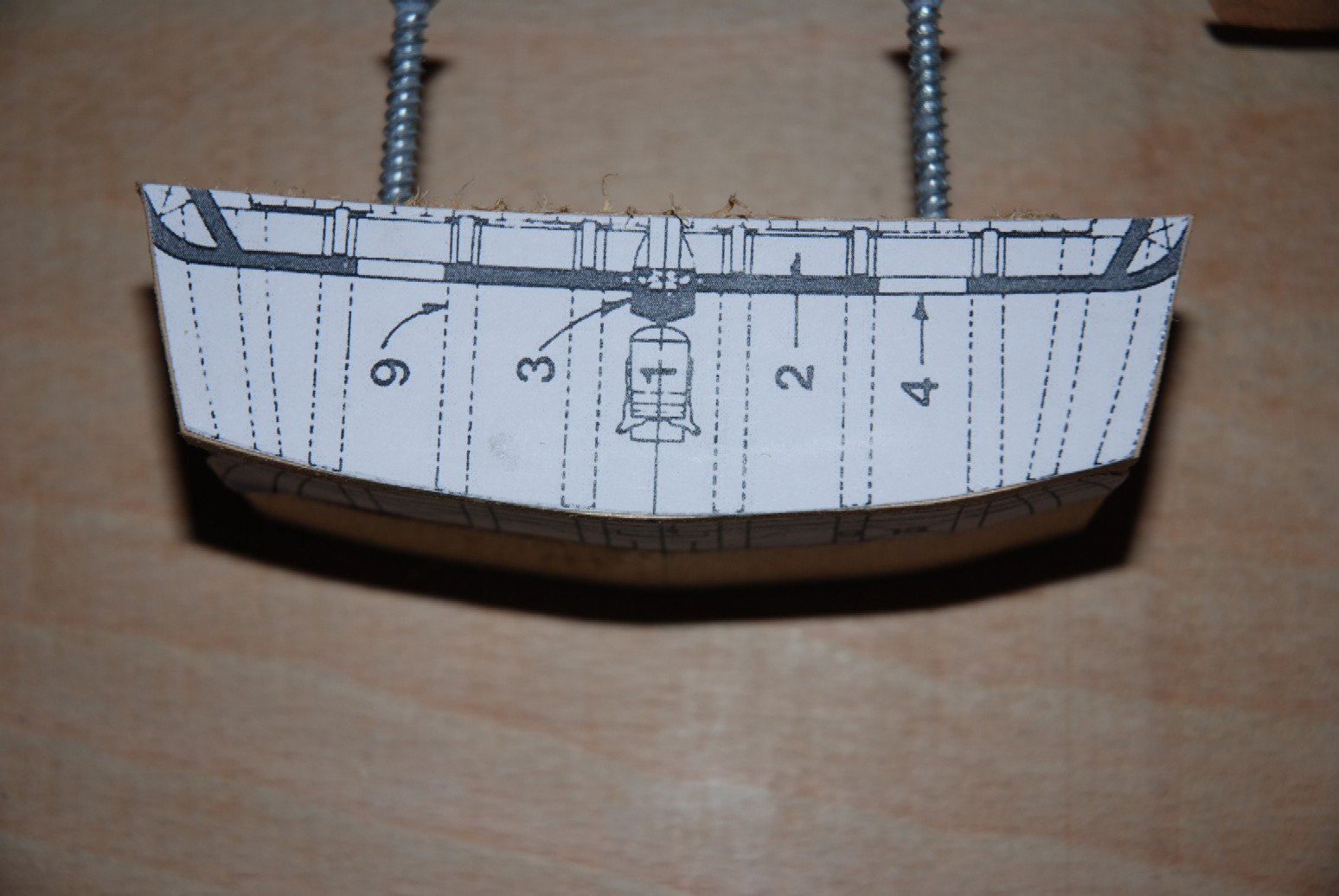
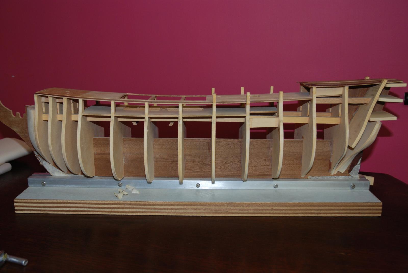
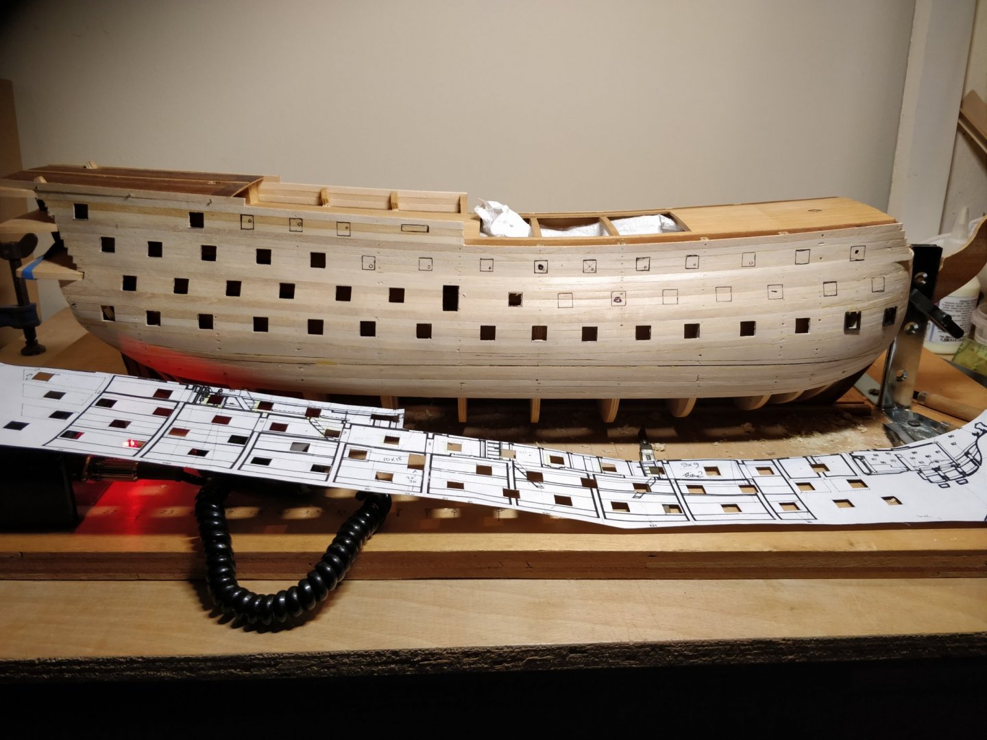
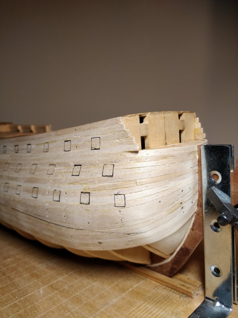
Hi everyone! I've restarted the build and got some first planks on! I've left the bottom planks off until finishing the gun port cut outs to let the debris out. I used a template to mark the ports and checked several stations from the main drawing. Each side was rechecked with a height gauge. The waterline was marked also as a reference. Had my first taste of spiling as somehow I miscalculated or moved the first few planks which were to have denoted the mid point. This was a bit extreme as each plank was full length but templates and Amati plank bender won the day. Next job will be the garboard strake and upwards only this time I'll be running stringers across to get a better view of spacings.
-
Thank you, I will have a good look around the site. It's great to see so much information from experienced modellers and novices alike. I started a build log ages ago now and must revisit it when I've got a few more planks on!
-
Does anyone know if Corel provided more up to date instructions for this build? My booklet seems dated with a paucity of information presumably because it's aimed at the more experienced than myself!
-
Gun ports
Sheerline replied to Sheerline's topic in Building, Framing, Planking and plating a ships hull and deck
Thank you everyone for the useful pointers. As a precaution prior to planking I measured from the main deck the distances at each station down to the next. Using all in combination hopefully it will come right. Think I need to assemble a gun carriage too in order to estimate the bore height above deck. Rigging seems a long way off but enjoying every minute watching the ship grow. -
Gun ports
Sheerline replied to Sheerline's topic in Building, Framing, Planking and plating a ships hull and deck
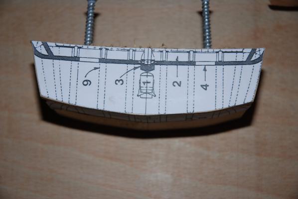
Thank you for the input. These are very useful tips which I shall employ. One thing I might do is measure out the four most distant ports from the drawing and lightly mark them on the hull. Then if I overlay a printout see if everything coincides. The hull curvature may impact upon this so will proceed with caution. It's been so long since I worked on the model I'm having to revisit lots of things! Thanks again, much appreciated. -
Hi folks, I'm a relative newbie planking up Corel Victory. When it comes to marking out the gun ports should I reference each one by measurements from the drawings or can I do a tracing and lay it alongside? Thank you in anticipation.
-
Thanks Grant, Your finished model looks terrific. I hope mine turns out nearly so good! I'm having a look at the other Corel builds at this scale to get further guidance and importantly avoid mistakes. It's nice to know others are in the same boat as it were. What a great resource MSW is. Will update when I've got some planks on. Cheers, Chris
-
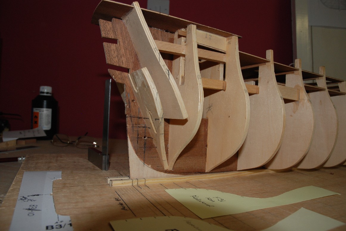
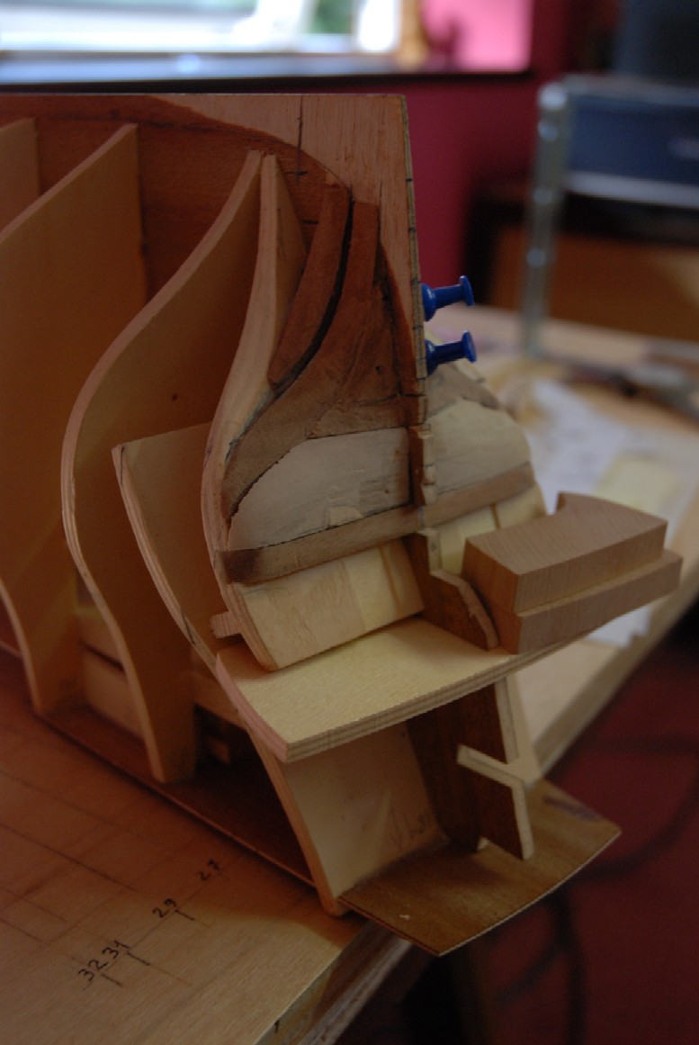
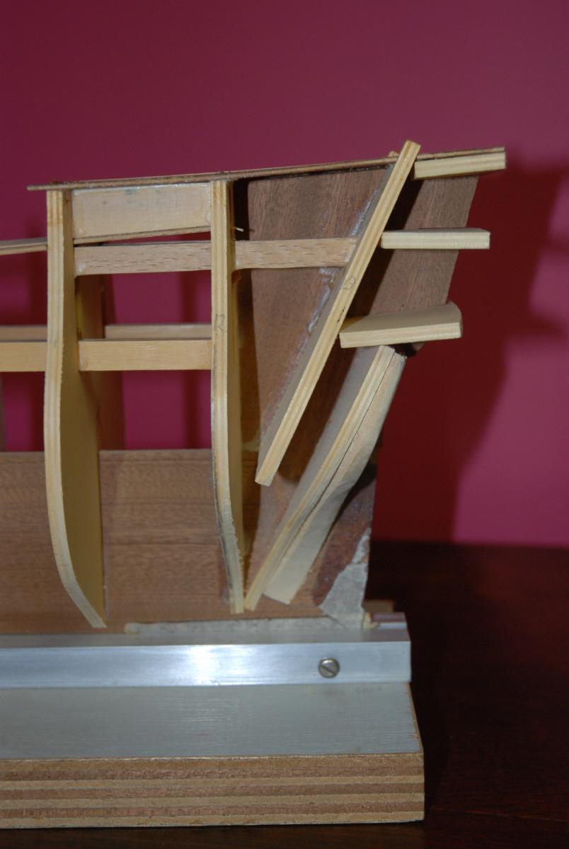
Apologies for absence recently. It must be a while since I last posted. Have had numerous domestic chores to sort out including long runs of fencing due to storm damage. Anyhow, back on the case now and I note several others are building Corel Victory 1:98 which is fantastic news. I must have a look at these later! I will attempt to post some photos of the work I did on the stern section, the fitting of a wing transom and a block made to represent the upper and lower stern transoms. I managed to complete the stern section infill blocks and profile each one, blending into the next. This seemed much simpler to me as I could sight back to the previous frame markings and chamfer to suit. Frame 14 had to have quite a bit of reprofiling done which I think is mentioned elsewhere by others. All profiles for this block were scaled up from the 1/192 drawings by McKay's book.Cut out sections were then overlaid on the wood and the main profiles jigsawed. The other lines seen were extended and the wood chisselled as shown. I think the result looks better than I personally would have obtained from items 50 and 51 in the kit. It's been quite a learning curve getting this far even, forcing me to do more research in order to get this stern section more accurate but it was worth it. Might fit items 31 next for the gun mounts/stiffeners and then run a few planks down the hull to see how they fit. Got to step the masts too before I get too far down the line! Bye for now.


-
Pics hopefully! Apologies if not in order. Chris


-
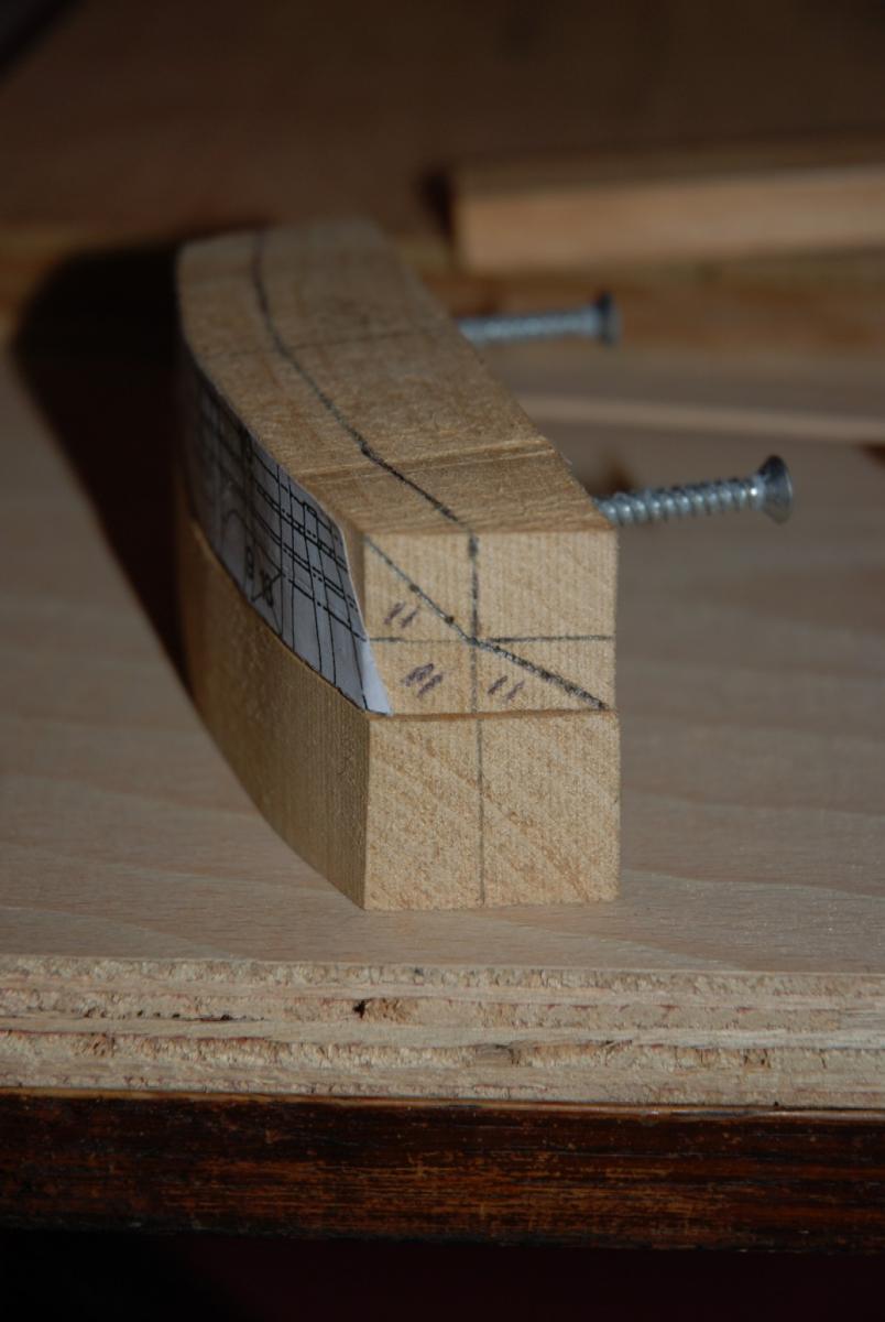
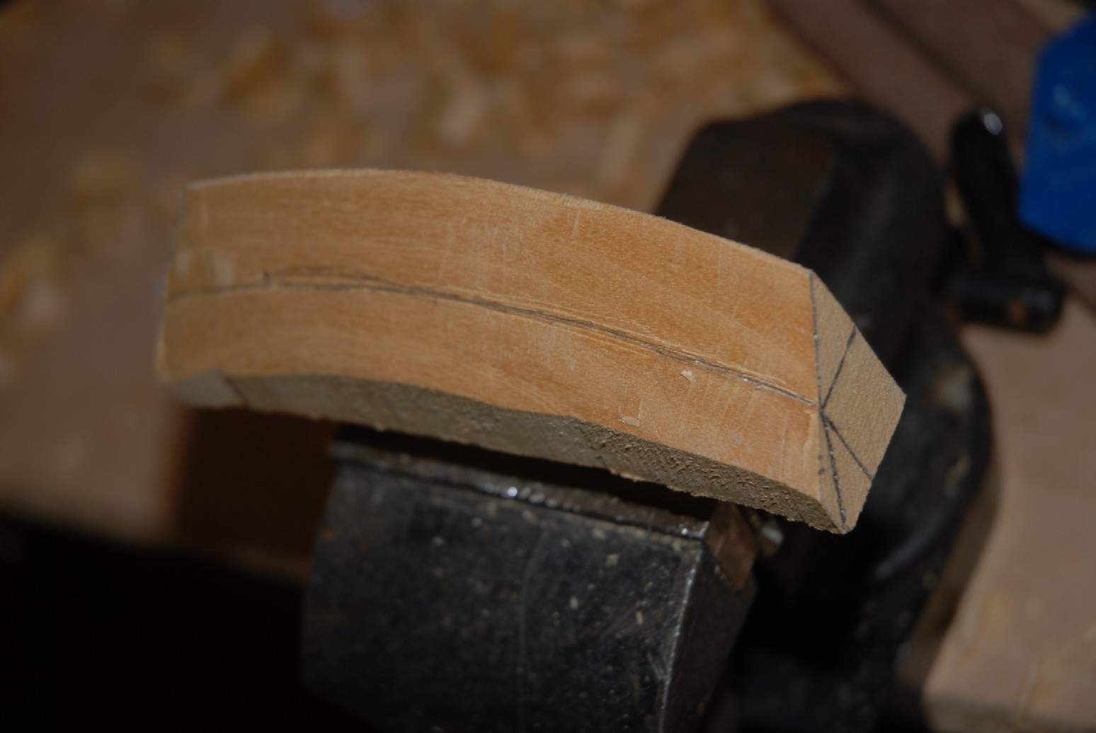
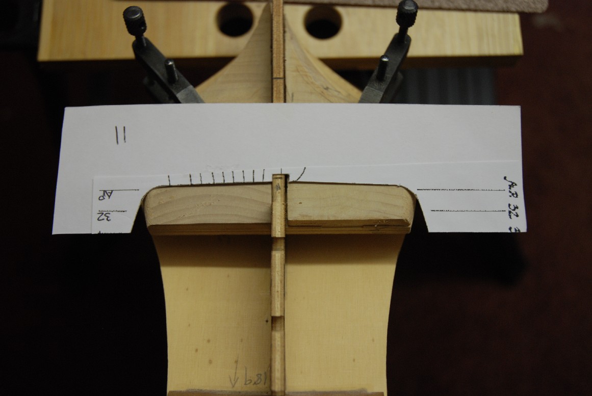
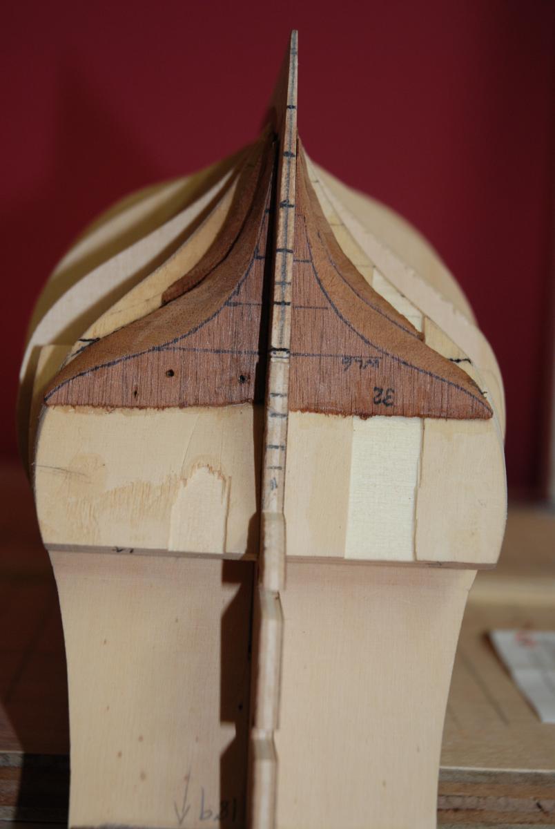
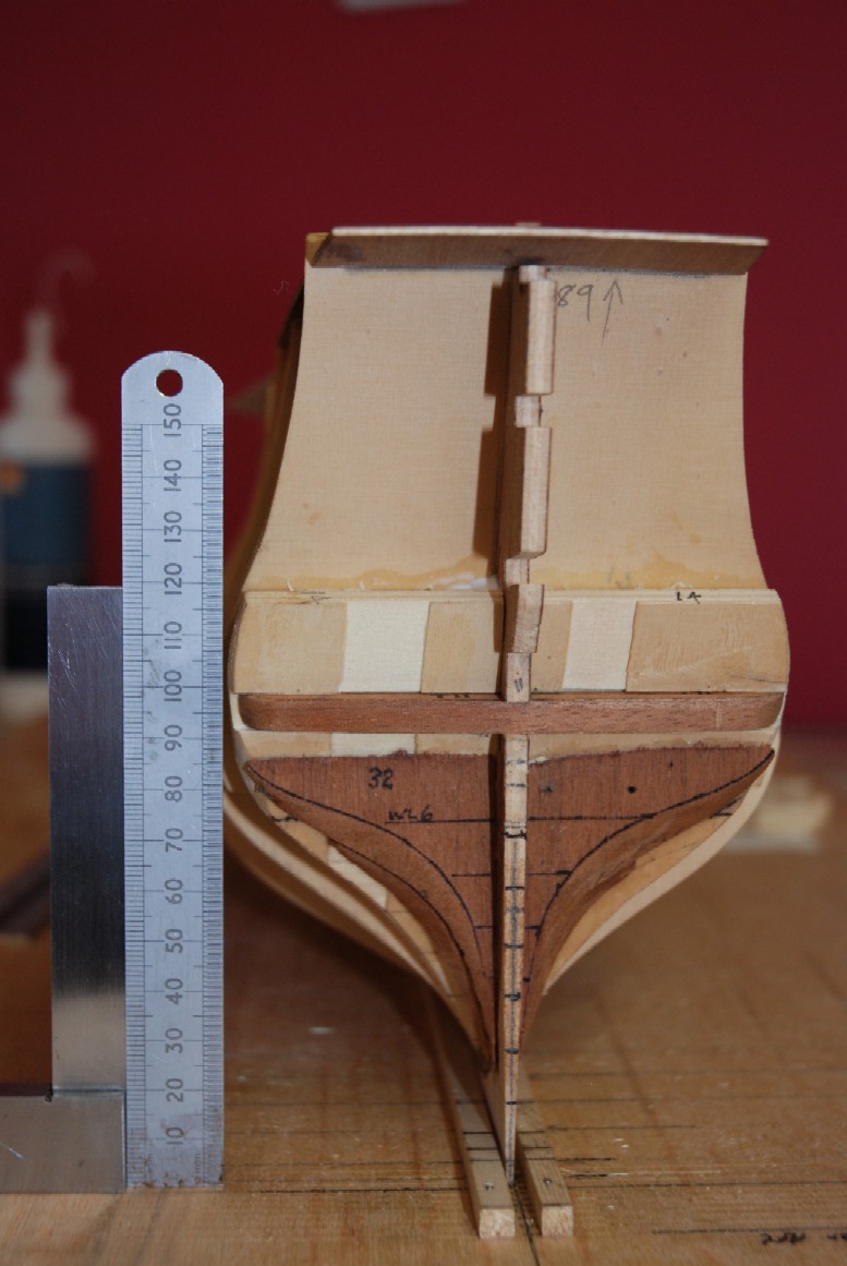
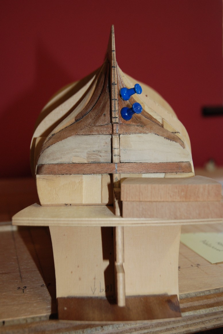
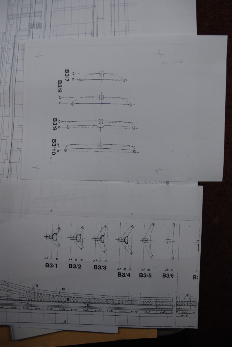
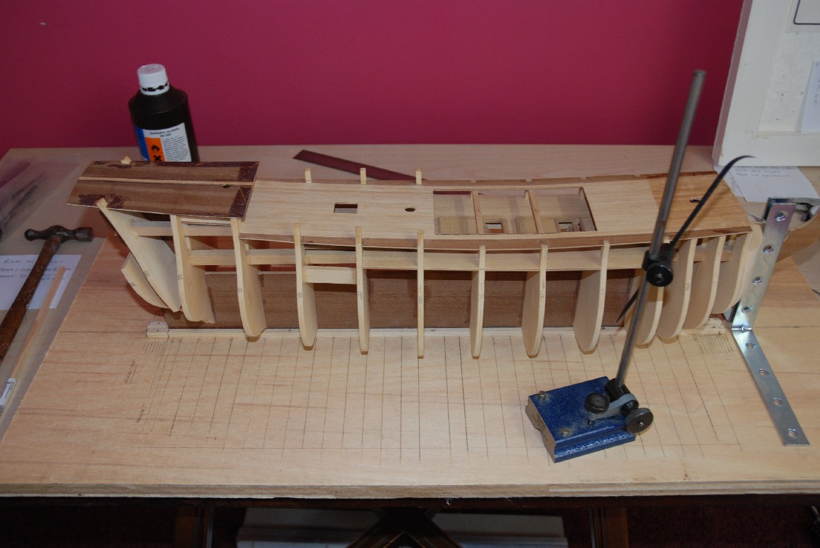
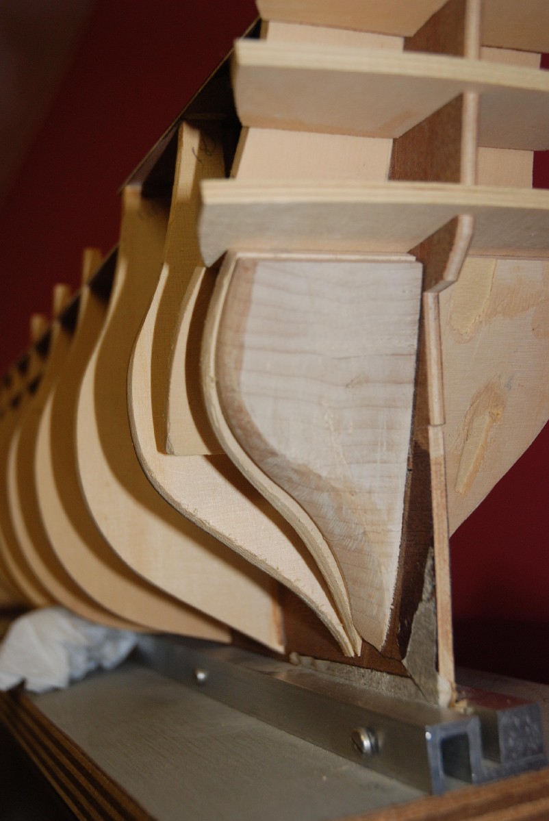
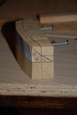
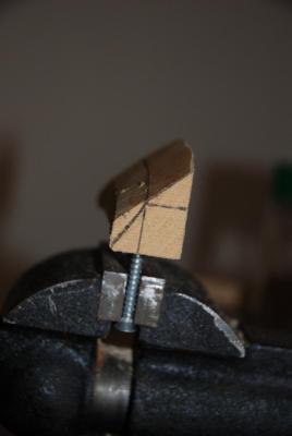
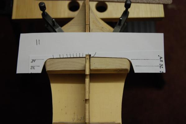
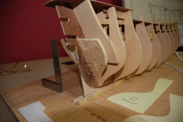
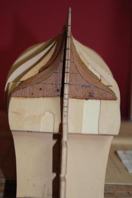
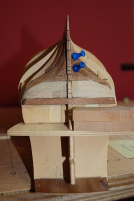
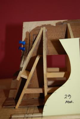
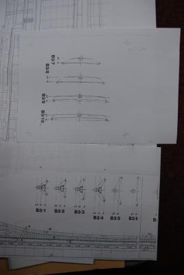
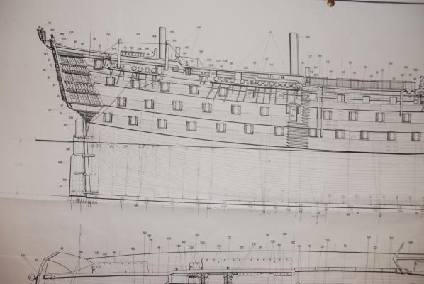
Hi all, It's catch up time not that I've done a great deal apart from fixing sheds and other domestic duties. I'm hoping the pictures will speak for themselves as I abandoned the supplied stern block filler idea and did a bit of scratching. I started by making a set of templates for frames 29,31 and 32 from reduced Admiralty sections. Added to this was McKay's sections for the transoms and bearding line. Getting the dwngs all matched up took a while but my ever patient printer is as keen as i am fortunately. I've managed to taper back the keel fore and aft, and also the sternpost section down to one lamination of the ply at it's thinnest. The notion is to thicken it up again on planking as noted in other texts. Firstly, as advised, I marked the waterlines on the stern area which gave me a much better impression of things. I have fitted station 31 and 32 profile inserts using hardwood and tracings from the drawings. These are heavily chamfered to fit to the underside of frame 14. I feel though I shall have to be a bit careful when plank fitting and drill each hole so as not to split it out. Then a channel was chisseled out of half the laminations in frame 14 to insert the transom profile transverse section.(No.11). I'm currently filling in the gaps and gently whittling away between the various parts to obtain a fair line. This time though I felt more confident because I had references to work to. It's clear (as per booklet intructions) that F14 needs more fettling to lay the planks in a smooth run! While I'm at it I'd better check the bow filler blocks I fitted by eye some years ago! To anyone following this do please bear in mind that to all intents and purposes I am a complete novice and am taking a bit of a flier at this. Bye for now, Chris PS Having ( finger trouble) uploading. Pics to follow!
-
Hi Clare, I haven't got that far yet! However, I did spot a good article on shaping this area using McKay's book which involves overlaying photocopied sections and then cutting to suit. Haven't thoroughly searched this site yet! The reference can be found at 'laukstreetshipyard.com' victory_sample-1.pdf I hope this helps somewhat, but I'm a little way off at the mo to comment further. Cheers, Chris
-
Hi grant, Still working on the below gallery stern section. I blew up and made Transom templates from McKay @1:98 to profile from stern post fwd but the angles didn't seem right. In the end I sent for admiralty ( modern version) dwngs of profile and section- non of which show buttock lines, just the waterlines. I was rather hoping I could lift off further frame profiles and bunch them up at the stern to give me a clearer idea and make it simpler to shape. I've noticed that the original filler block provided isn't really thick enough and doesn't extend to the Rabbet aft or indeed the bearding line below, hence my notion to put more frames in. I'm really tempted to rasher out the ( angled) top of frame 14 and stick my own vertical frames in aft of that point. I'm not certain if its possible to lift sections without these 'ere buttock lines though from what I've read so far. Anyway, failing that I'll stick in a bigger block and just chip away using profile 31 and 32 templates. If nothing else I am becoming more familiar with things and it's great fun making templates! Hopefully something more substantive next time I surface. Cheers, Chris
-
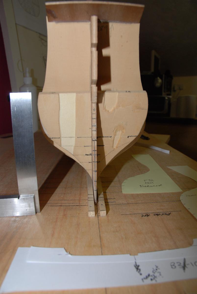
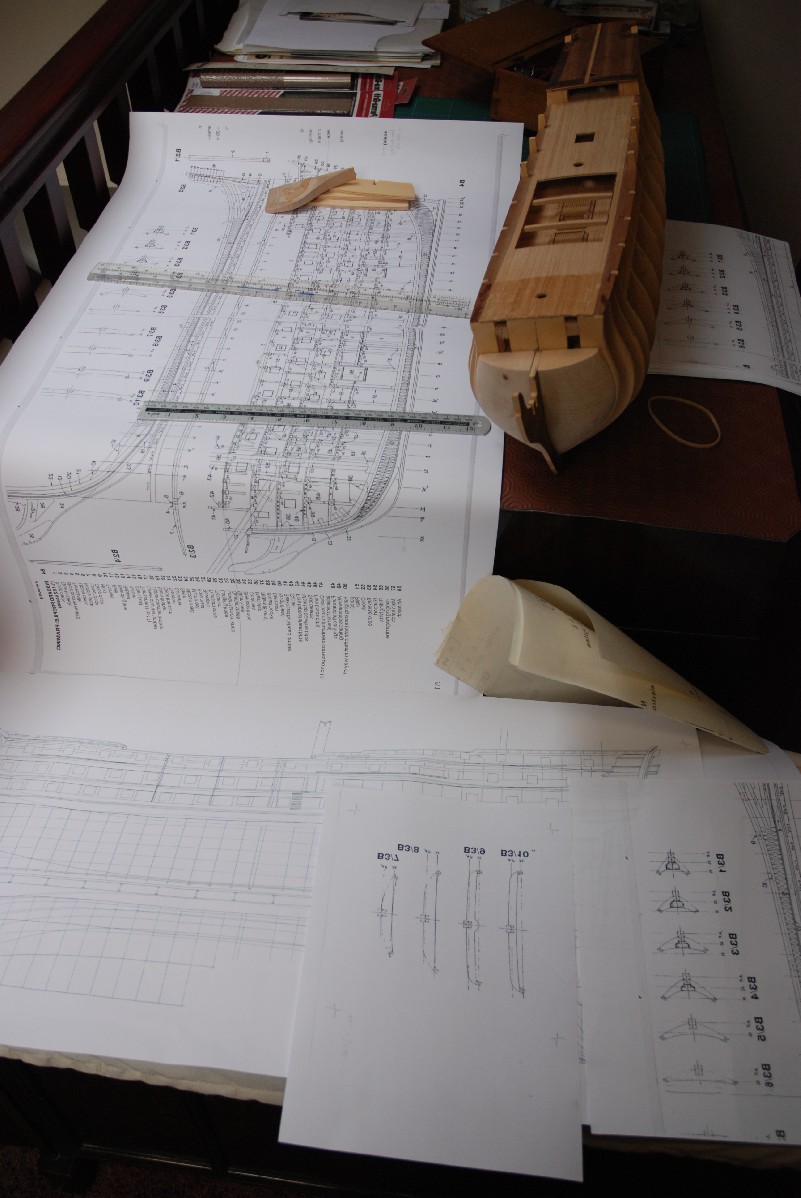
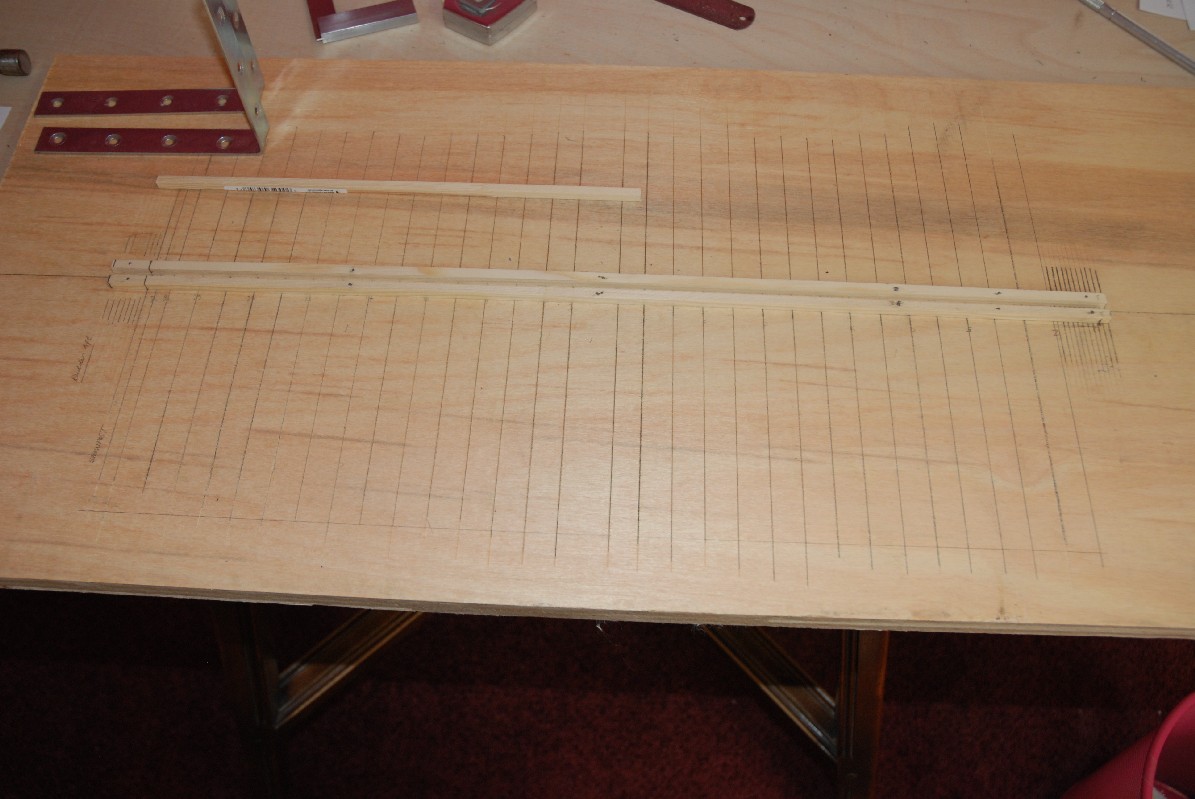
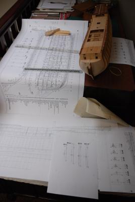
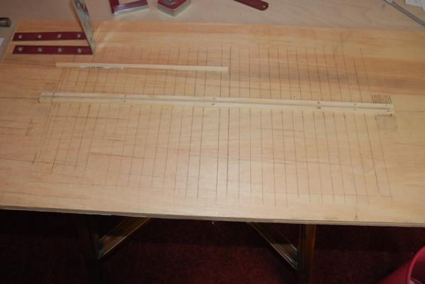
Thank you everyone for your input and encouragement. I'm not the fastest builder as you will have guessed, still only having limited time for the project. However, I have done now what I should have done right at the beginning and that is to get some proper references for the drawings supplied with the kit. Some of these have been transposed onto the original Corel drawing so I can now refer directly and also cross check where doubt exists. Sections have been copied to A4 for the purpose of making templates or possibly individual parts. I have also made a new build base board and marked it out as per drawing by scratching marks with pencil infill. The keel now rests right down on the board so vertical refs will be correct. Before, I found that needed to add on the thickness of the aluminium keel clamp which I no longer need to do. The photos (if I can upload them!) will demonstrate more than words what I've done. Next job is to make the stern templates and bite the bullet by putting tools to wood. One clanger I did make was to stick tape to some of the planking to protect it during inversion-big mistake! When removed it left lots of gunge and has stained the planking which I'm gently trying to tease off with solvent and a scraper.May have to replank it. Hopefully next post will show a nicely shaped rear end!

-
Hi Folks, This is my first time here so hopefully everything will upload correctly! This model was started nearly two decades ago but ended up in the loft due to career changes and various other factors. Primarily the build was stopped because I became petrified of ruining the stern section in the absence of any real dimensions or detail. No one will be surprised I guess that, yes, this was my first model which I got at an engineering exhibition whilst displaying some metal. At the time of purchase a guy tapped me on the shoulder and asked me that same question. He said I was looking at at least three years and in anycase shouldn't I start something simpler! His words came back to haunt me later..... Anyways, having found this wonderful website, here I am about to restart the build having found suitable drawings and other info from far and wide. My sincere thanks go to fellow member Grant Dale who started the ball rolling again and gave me the incentive to bash on. I won't say anything about the Corel drawings or the translated instructions as for more experienced people they're probably fine. My other sources now are; McKay,Longridge,Underhill,Roth and Dressel. My local printer has very patiently enlarged some 1/92 detail for me and I now have enough 1:98 drawings to check out the stern below the galleries. These were 'lifted' by the way by enlarging to 195.5% and seem spot on and agree more favourably with the Corel ones. My intention now is to make up some templates for the carving checks and take my time over getting this aspect right. I cannot honestly say how often I shall post but at each significant stage I will. Meanwhile 'management' keeps telling me they built the real one in around six years! Left hand down a bit! Cheers, Chris