Force9
-
Posts
407 -
Joined
-
Last visited
Content Type
Profiles
Forums
Gallery
Events
Everything posted by Force9
-
 Ahoy Mark... It is great to see all of the details associated with this plating kit from Maritime Models. It looks to be a terrific solution and your insights will surely help those who follow behind you... Should save lots of confusion and wasted effort for future modelers. My understanding is that some folks have come along behind and sanded down some of the prominent edges where the plates overlap to better blend everything to match the kit. I'm sure you'll be pleased with the result. Cheers, Evan
 -
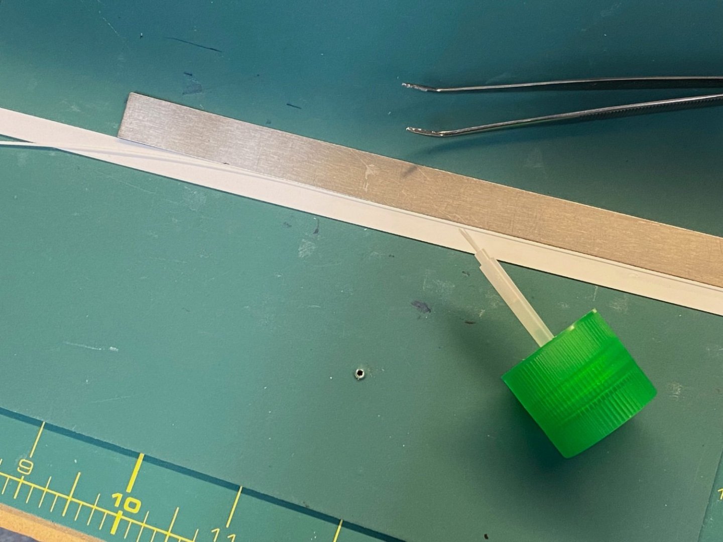
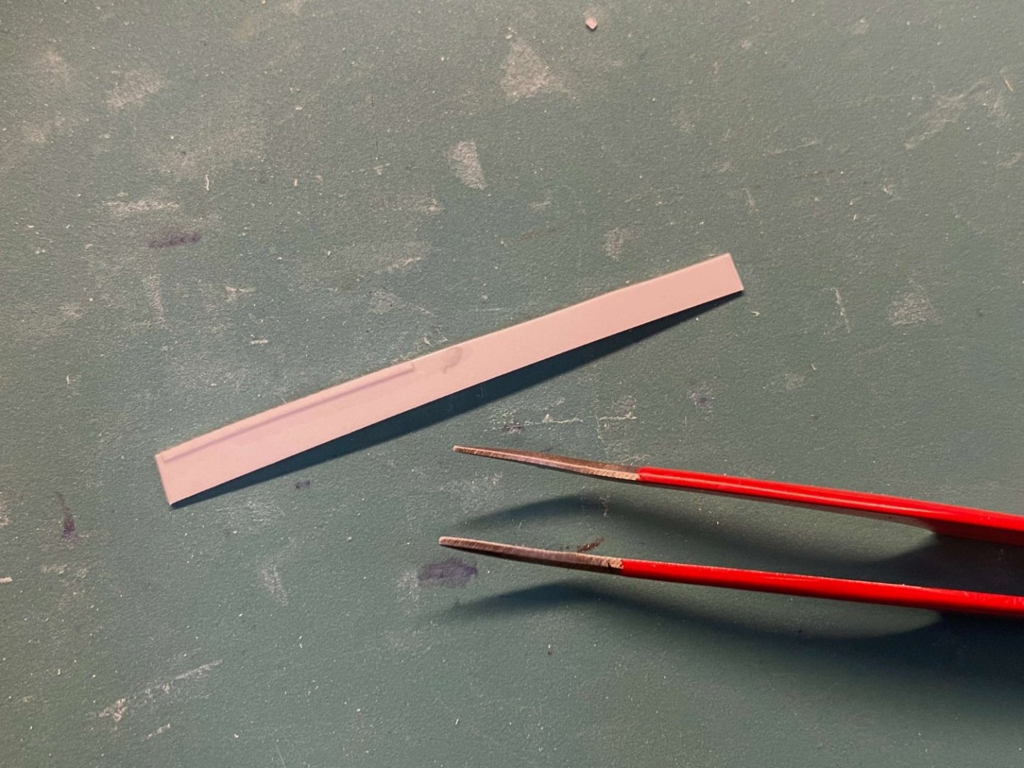
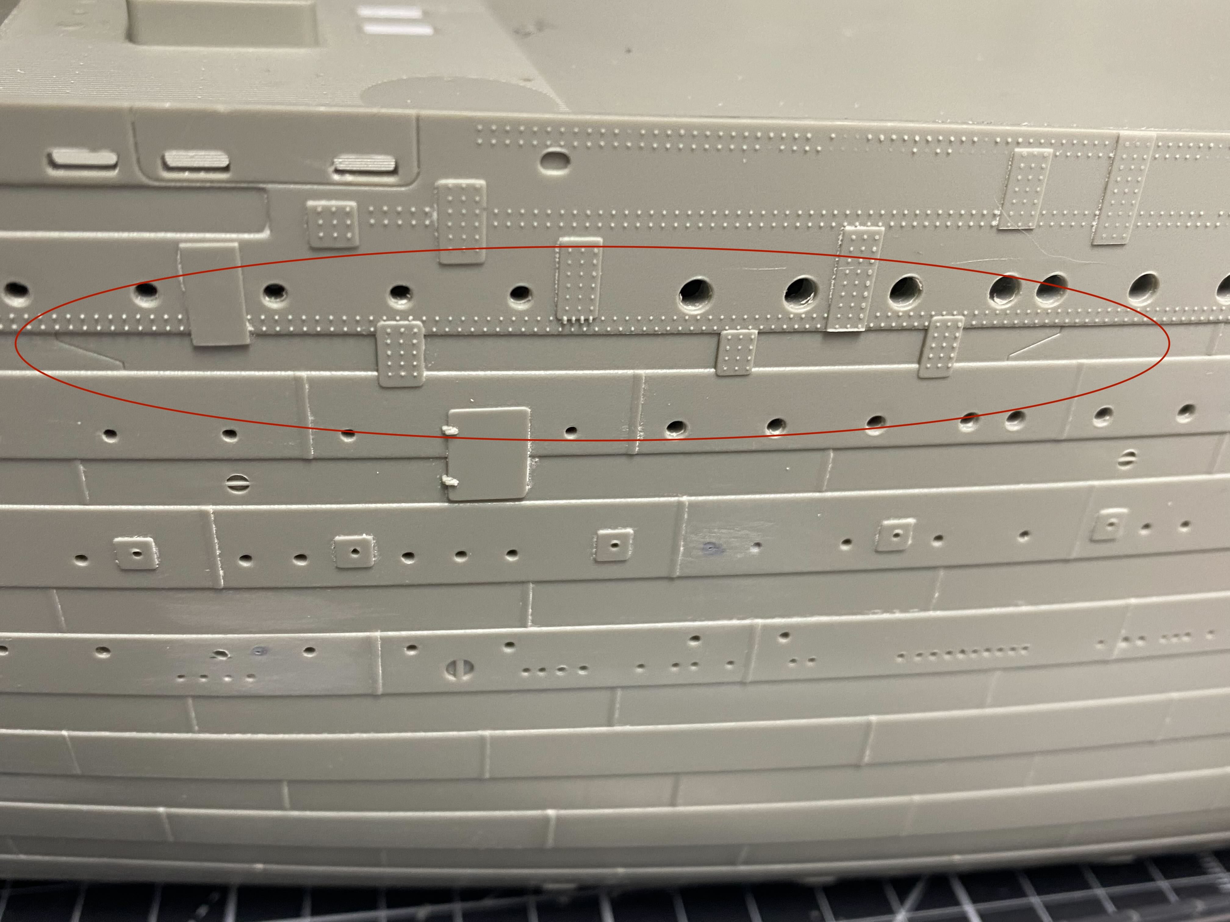
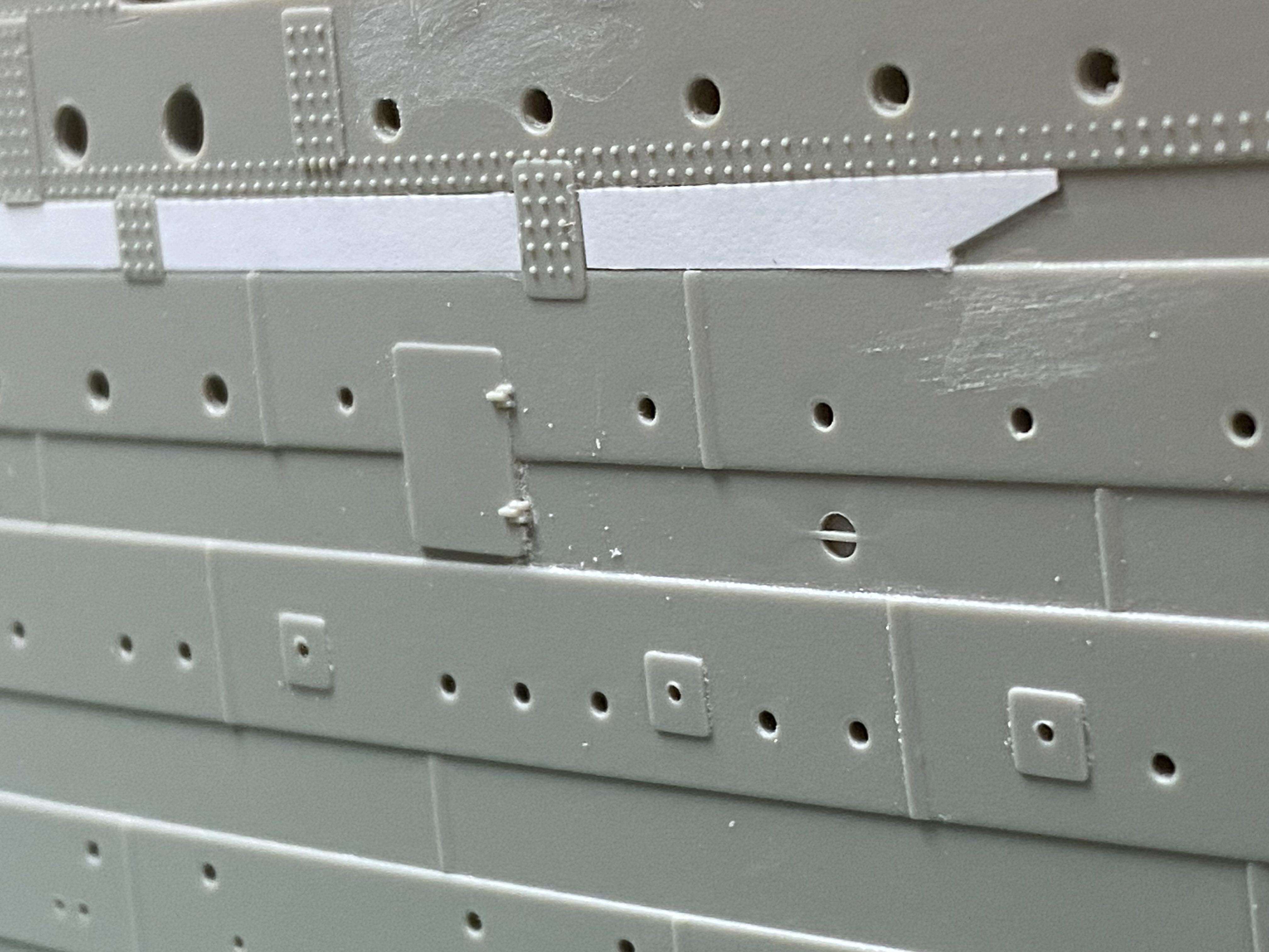
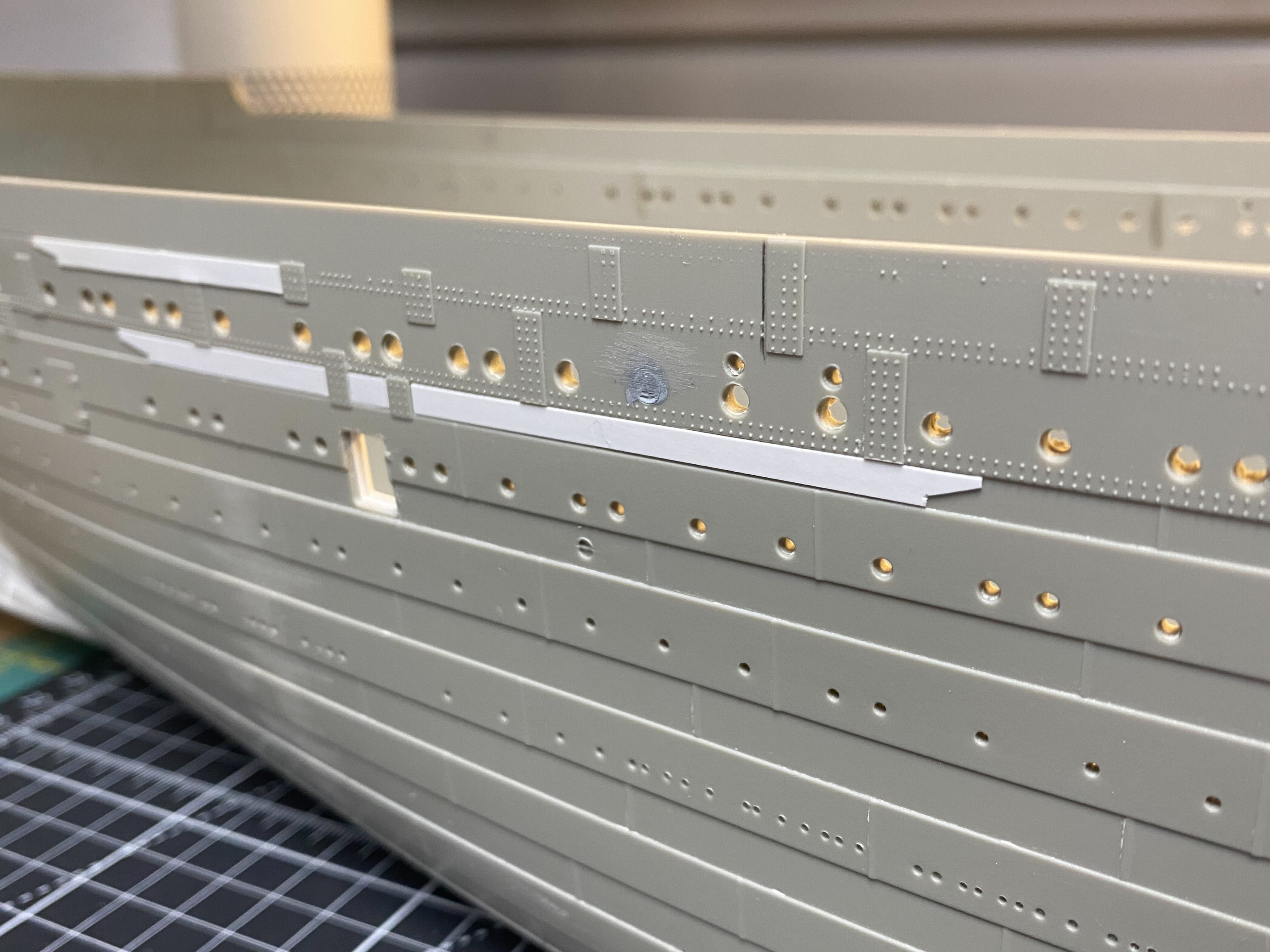
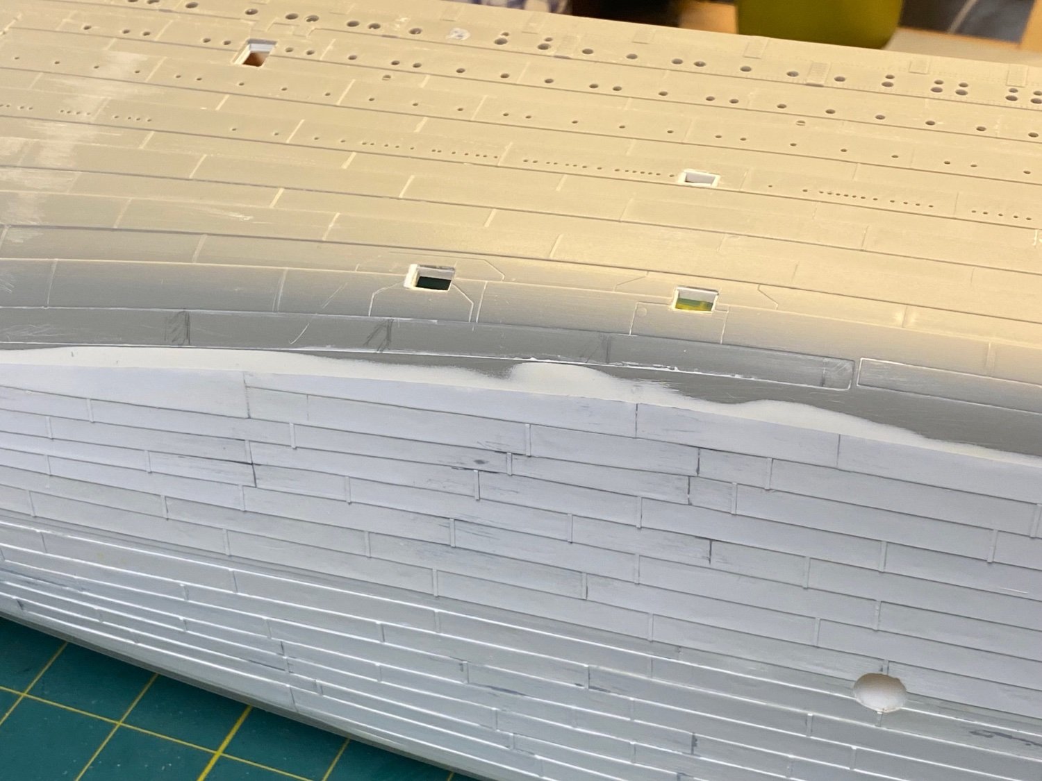
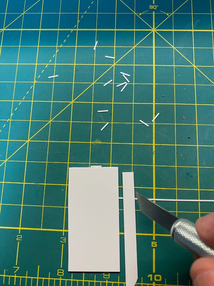
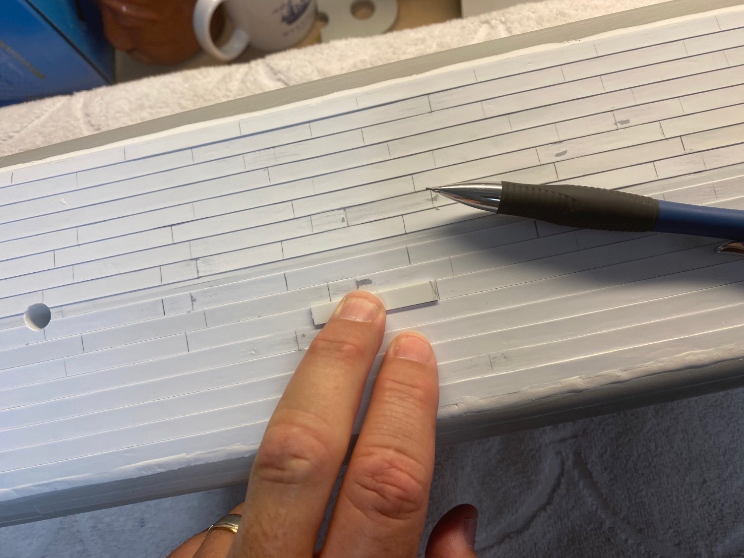
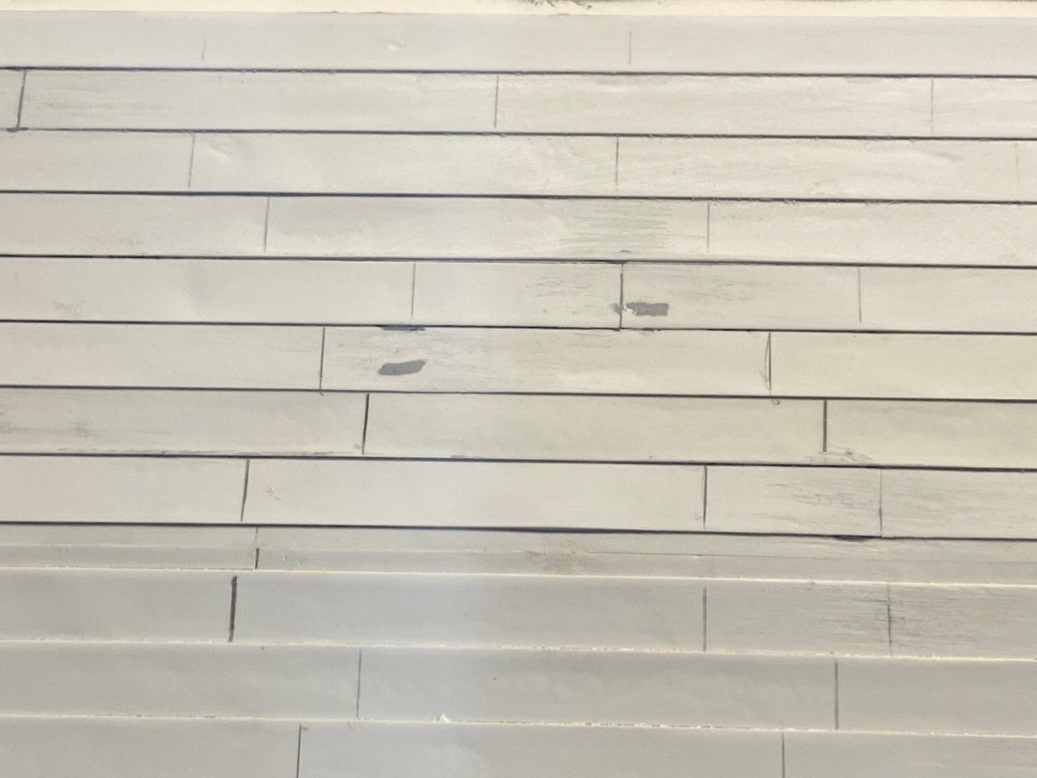
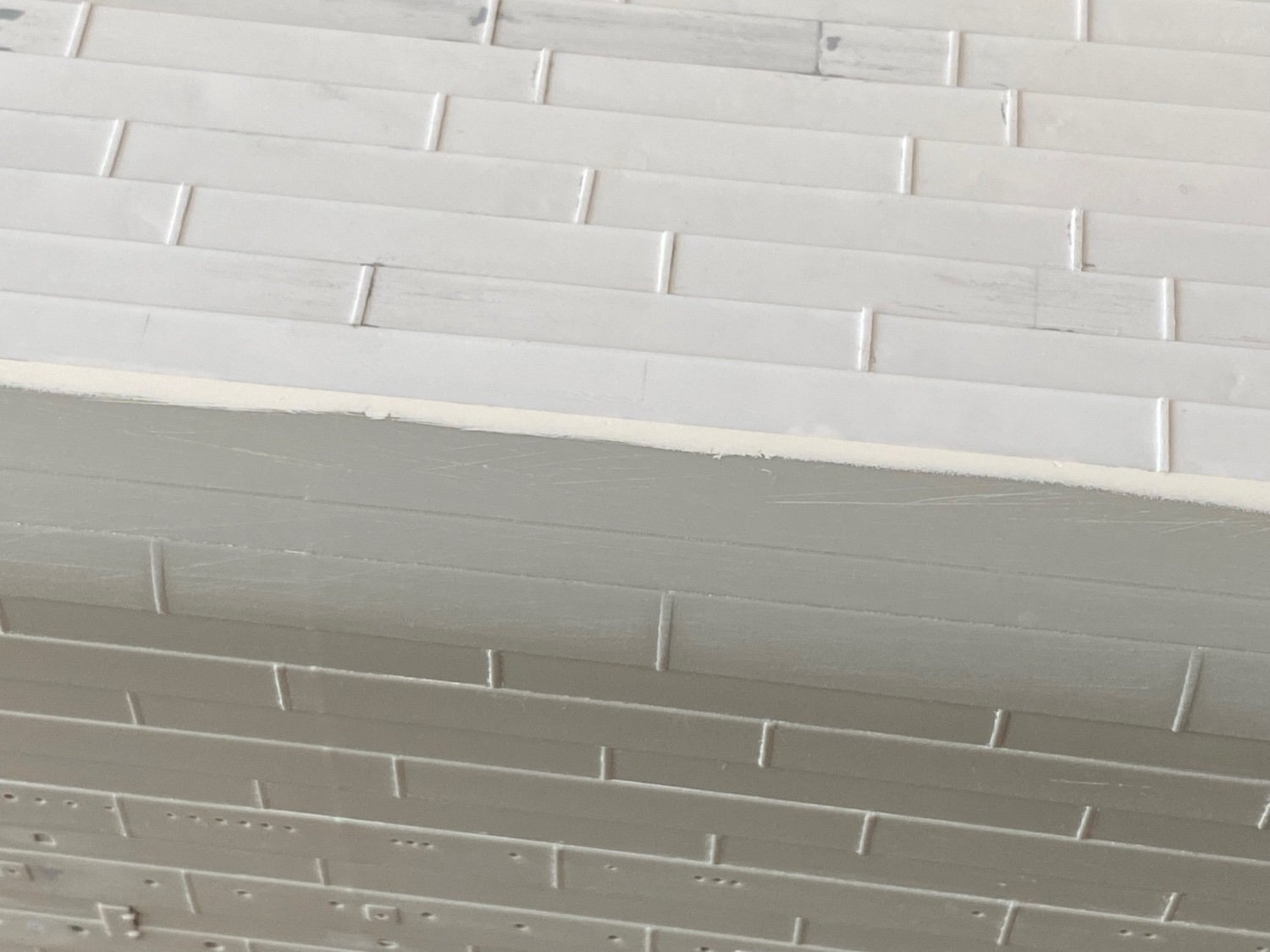
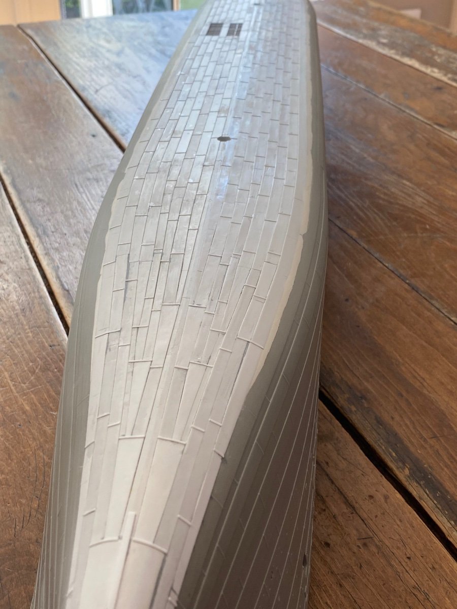
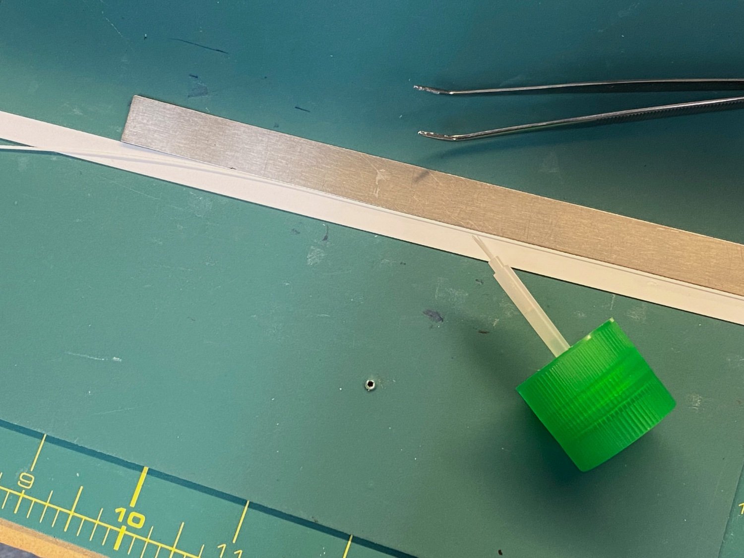
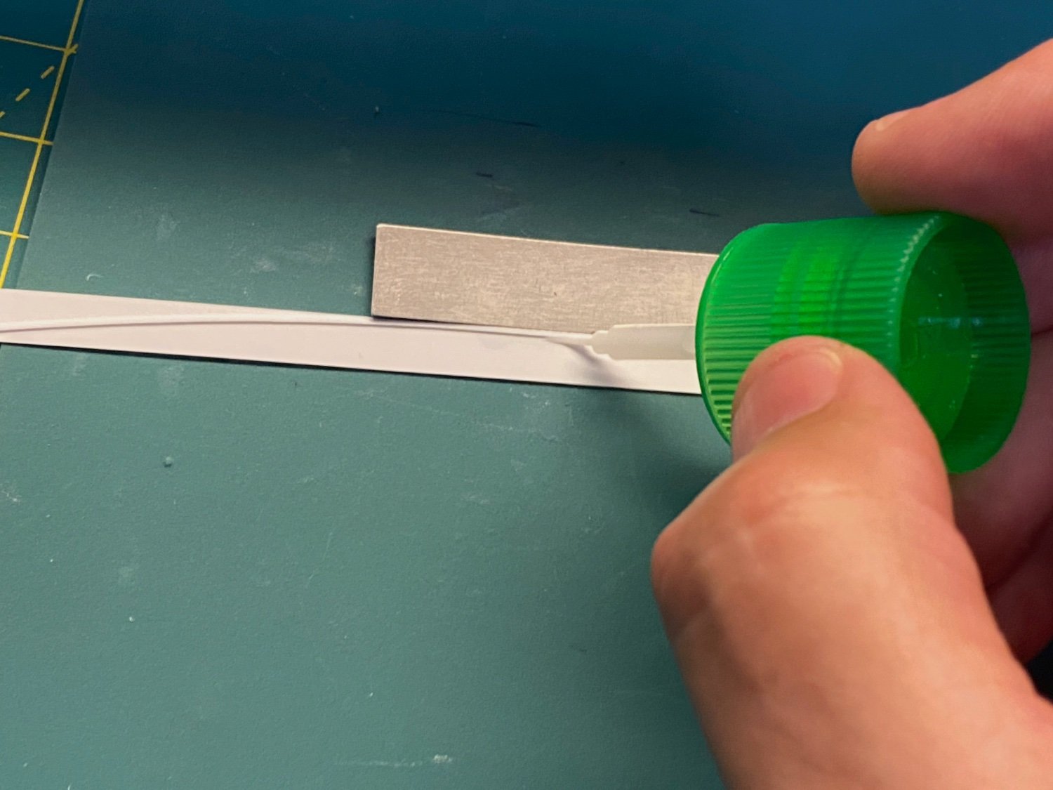
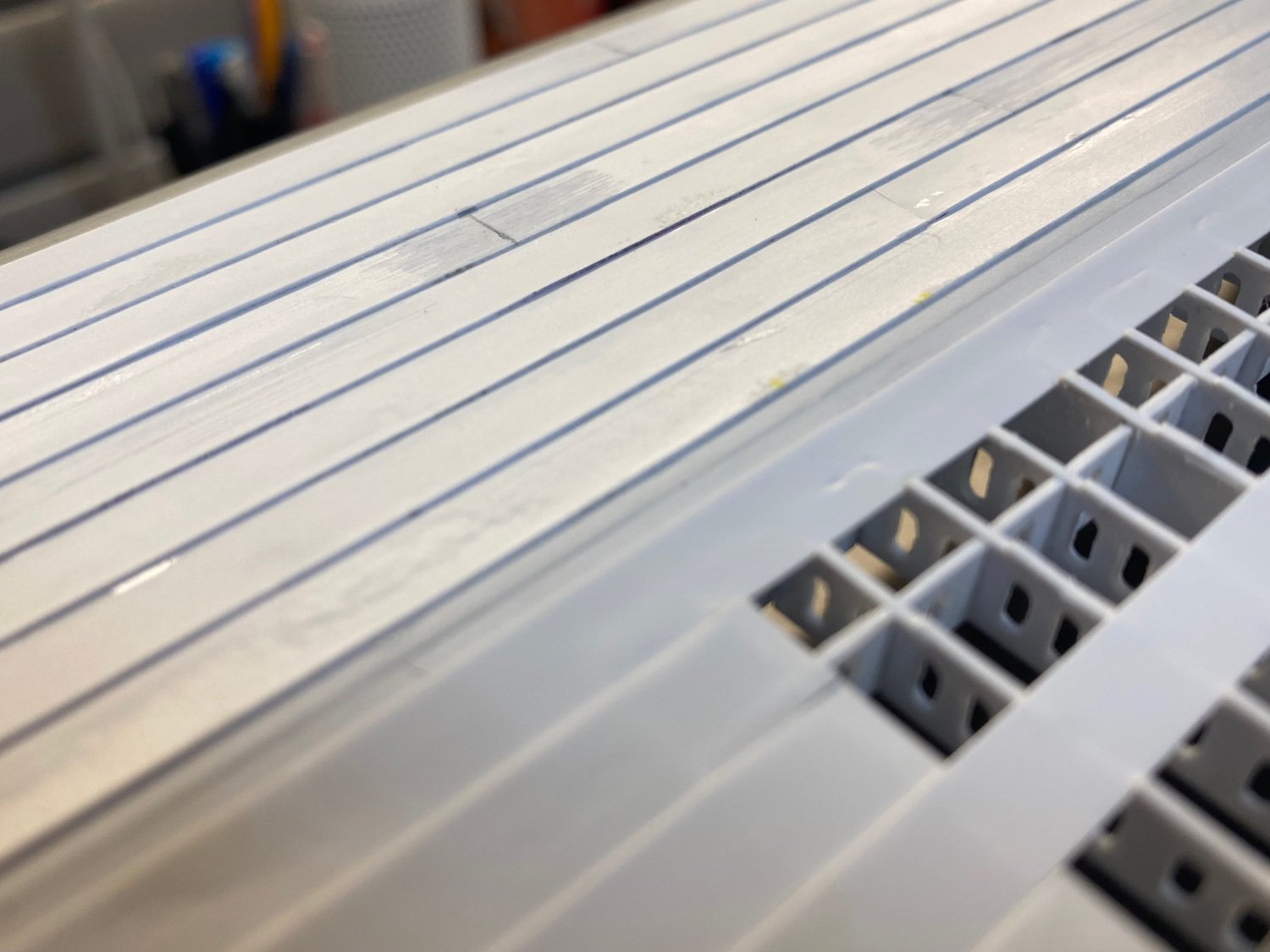
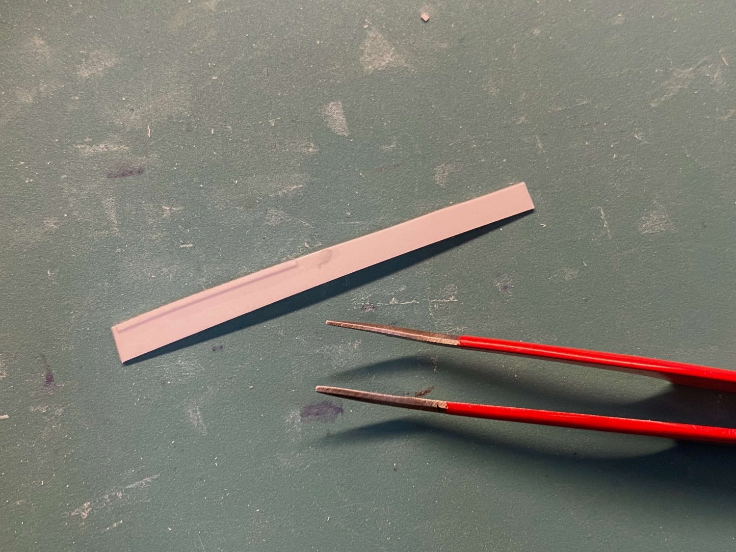
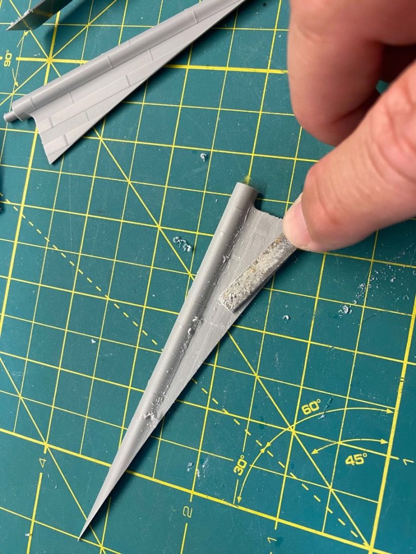
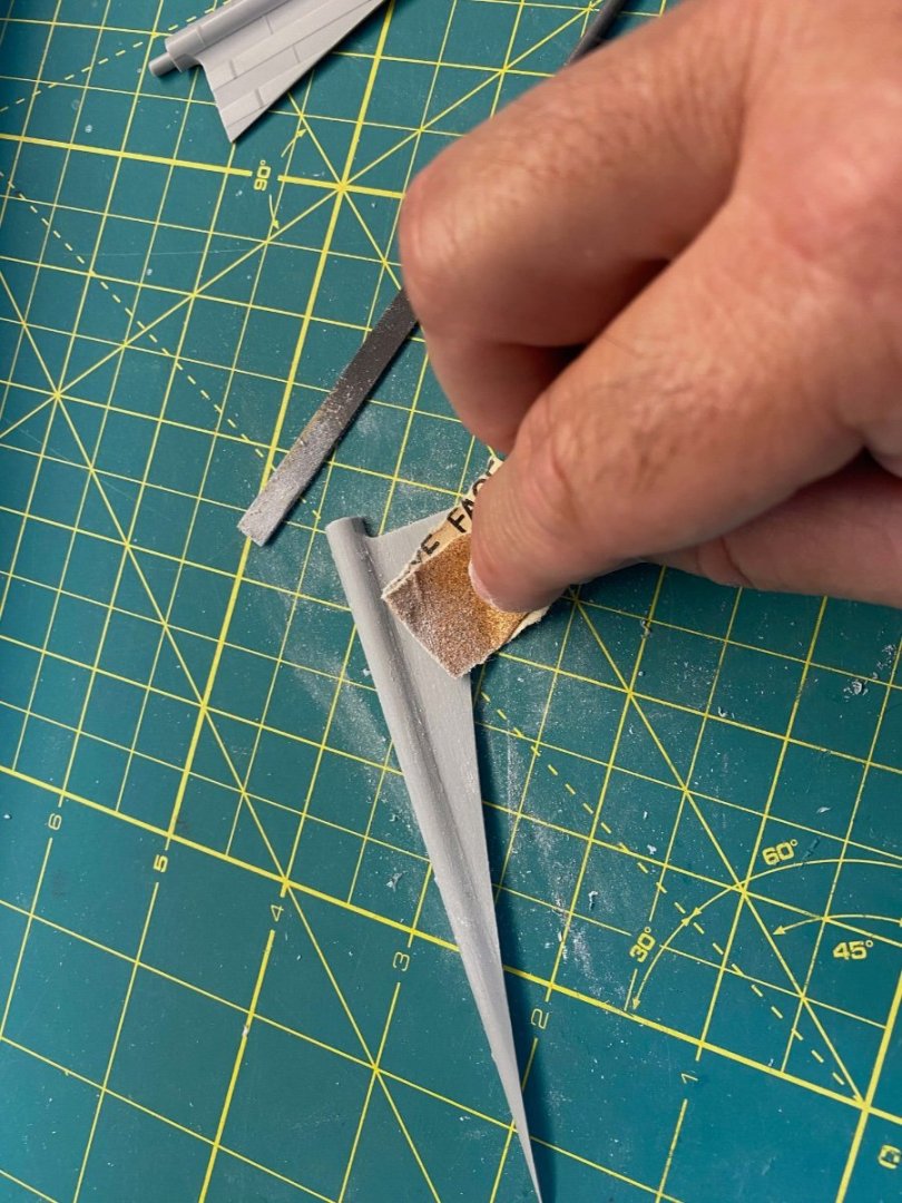
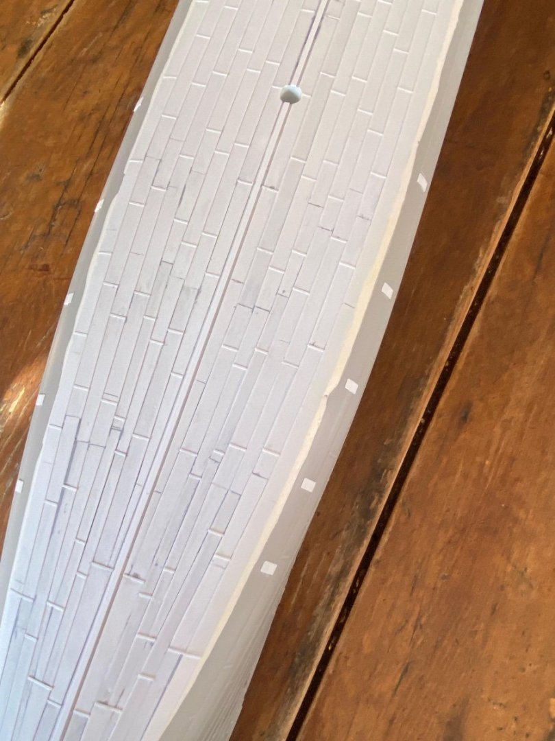
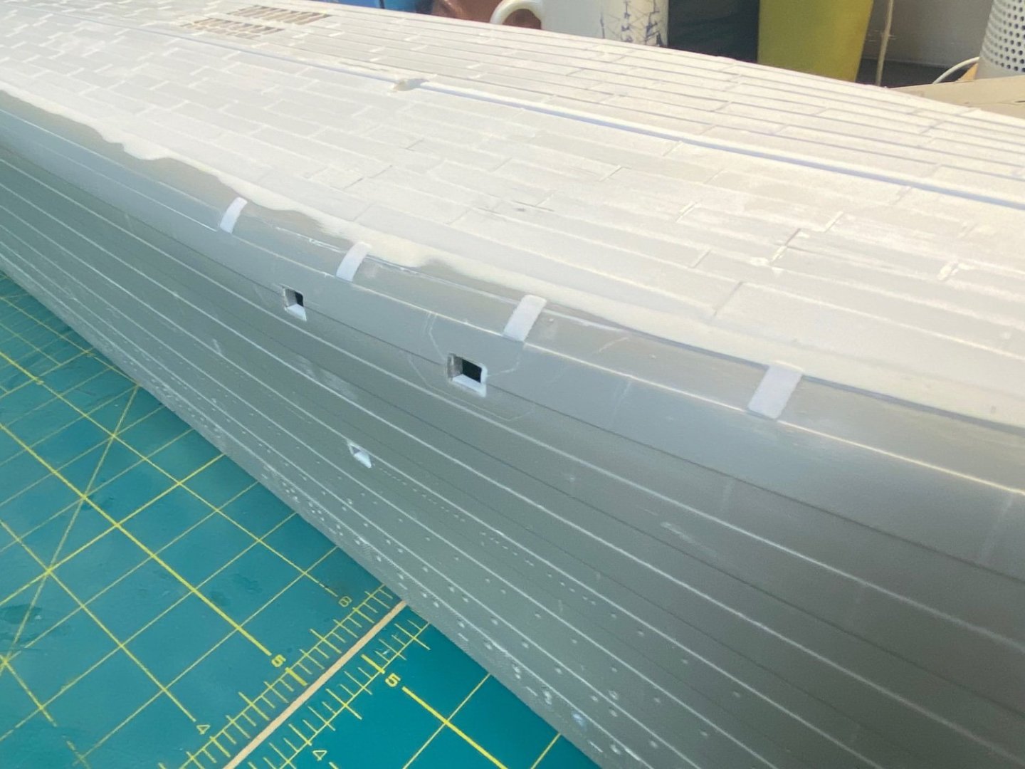
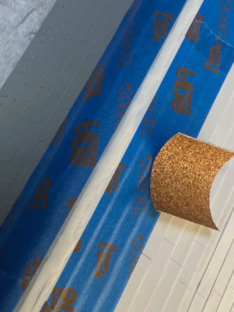
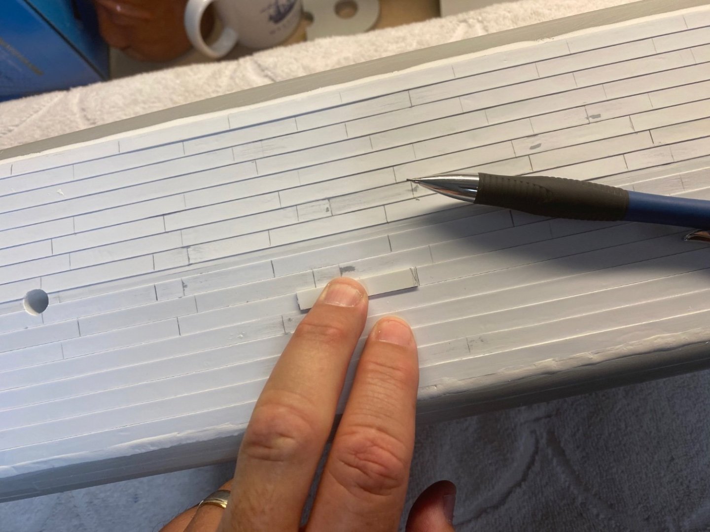
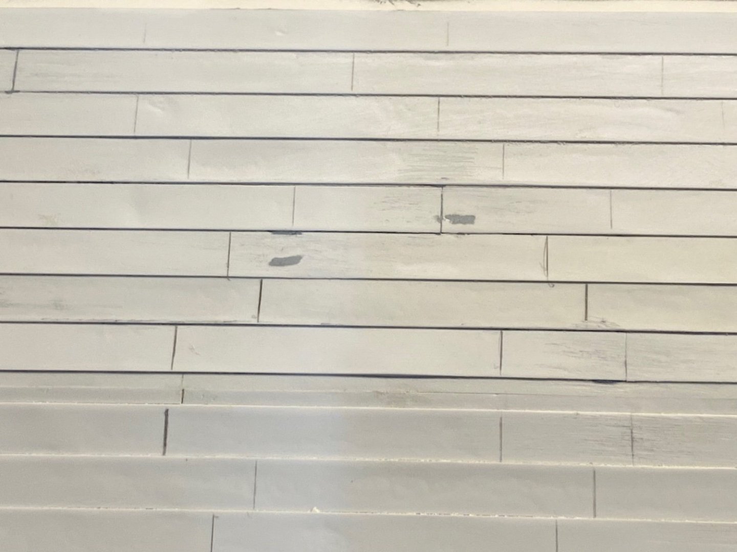
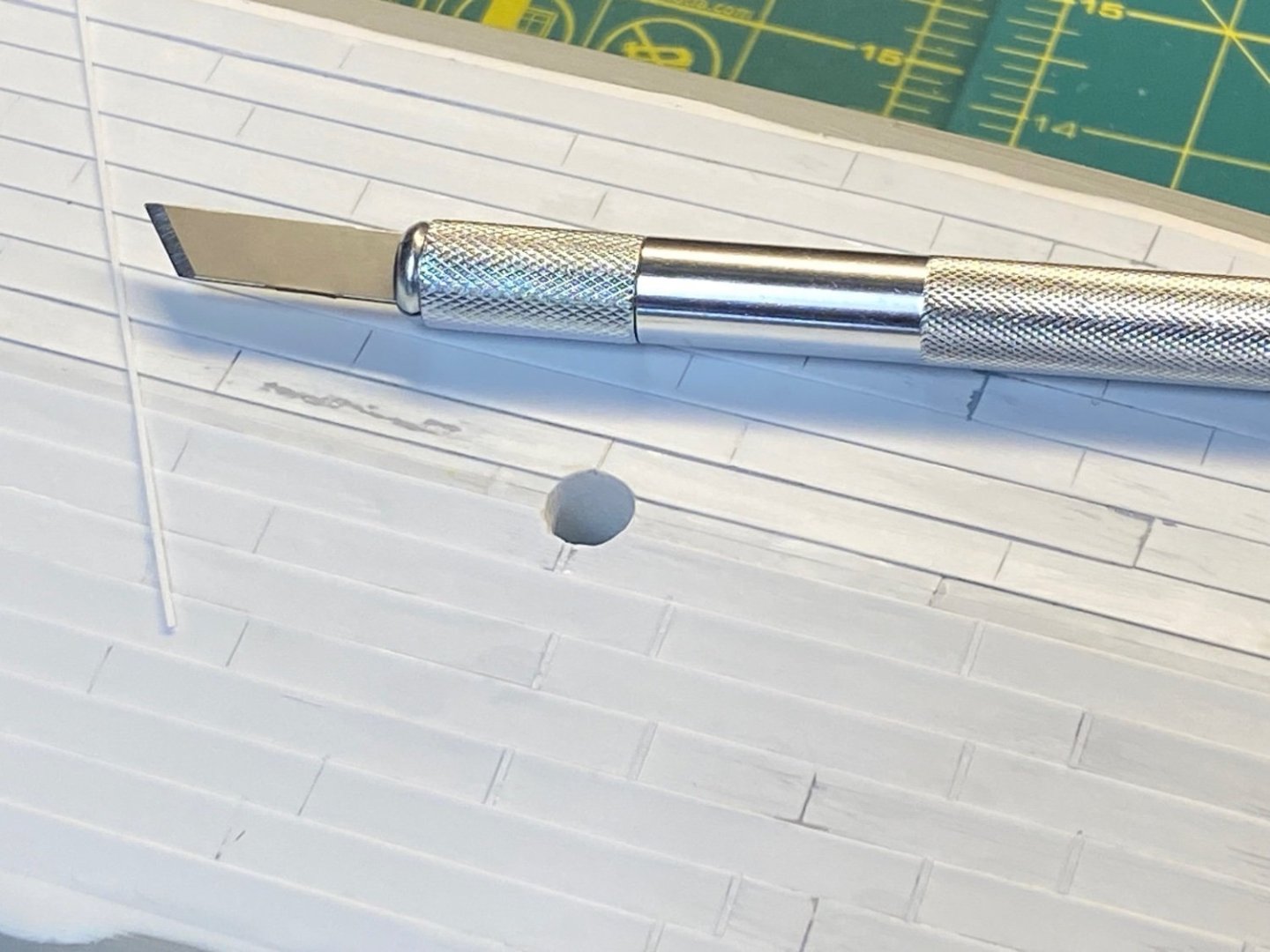
Thanks all for the likes! Double Strakes I added some styrene strips to represent the additional double strakes along the upper hull. These are only represented with faint outlines on the kit – likely a last minute addition by Trumpeter. The locations of these appear to accurately align with Robert Read’s ship profile drawings: I’ll assume that these were part of the suggestions submitted by the Titanic Honor and Glory folks and Trumpeter tried to accommodate them without completely redoing the initial plastic injection molds. I sized some strips from a sheet of .010” styrene and used a sharp blade to cut the angled shape of each end. I’ll come back along and fill the narrow gaps with thinned Tamiya Putty before priming the hull. Very simple to do and adds some good detail. Cheers, Evan

- 145 replies
-
- 10
-

-

-
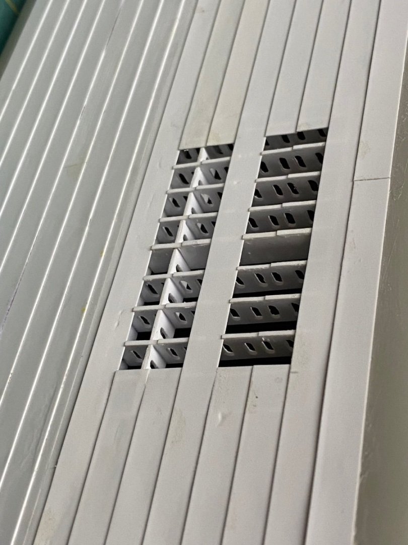
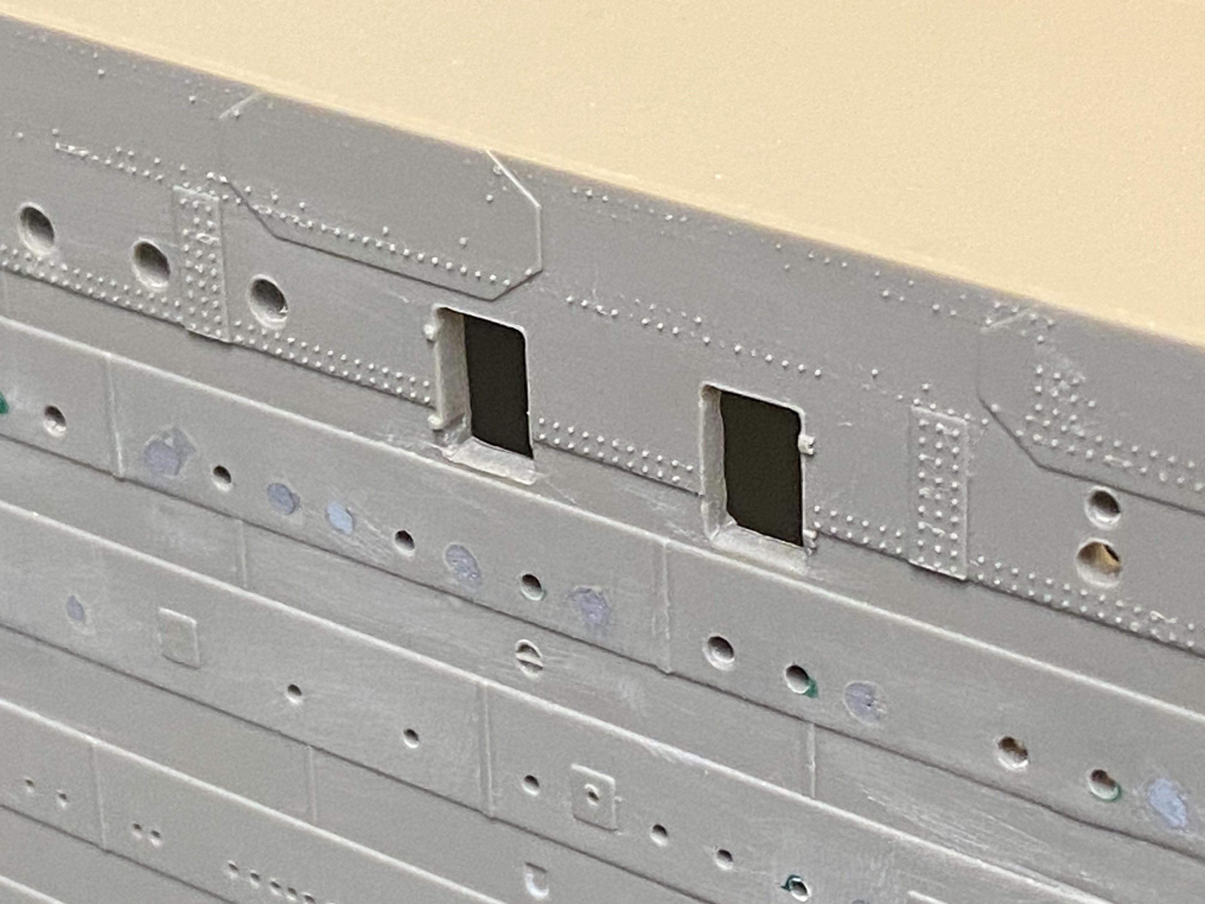
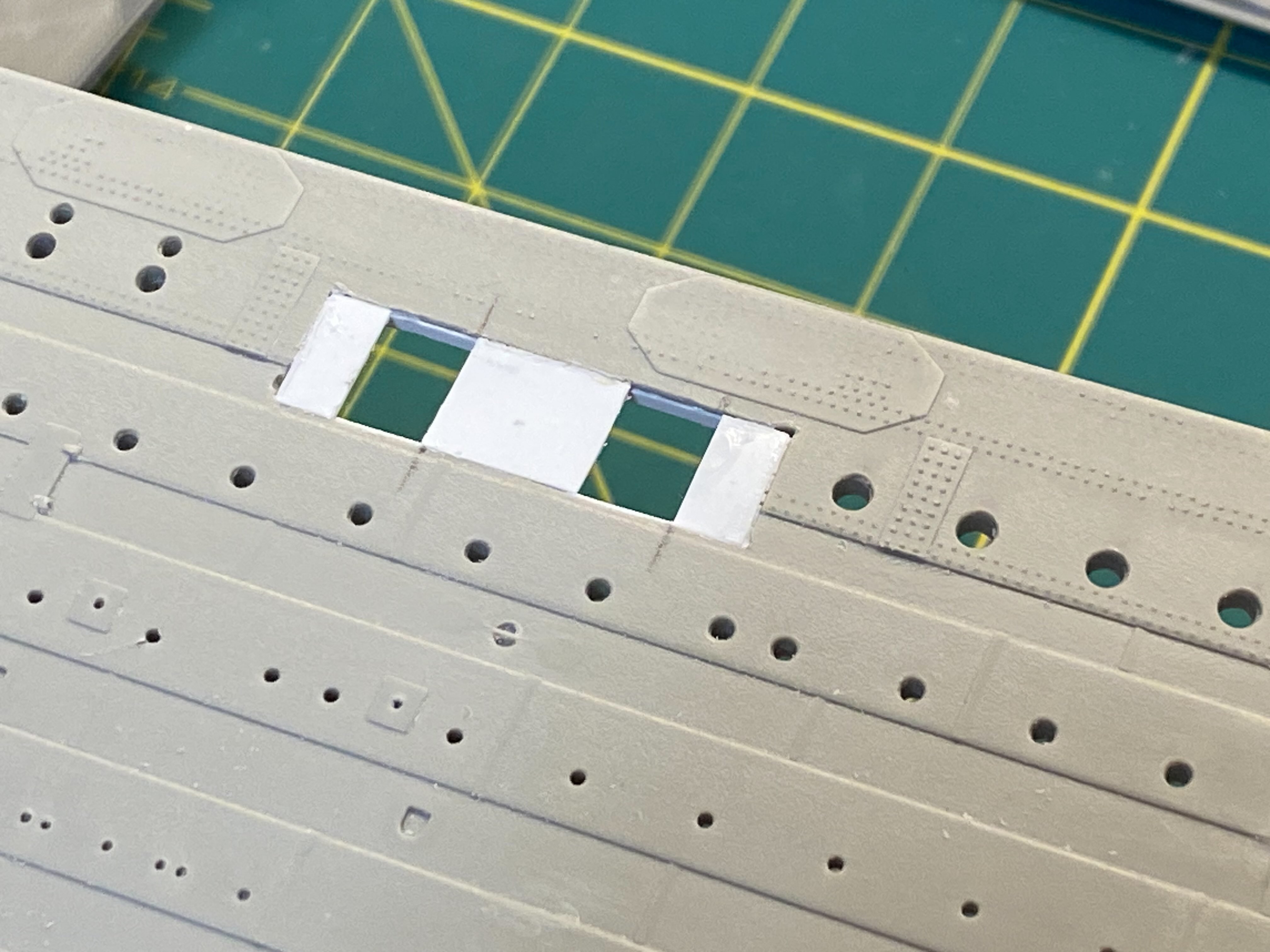
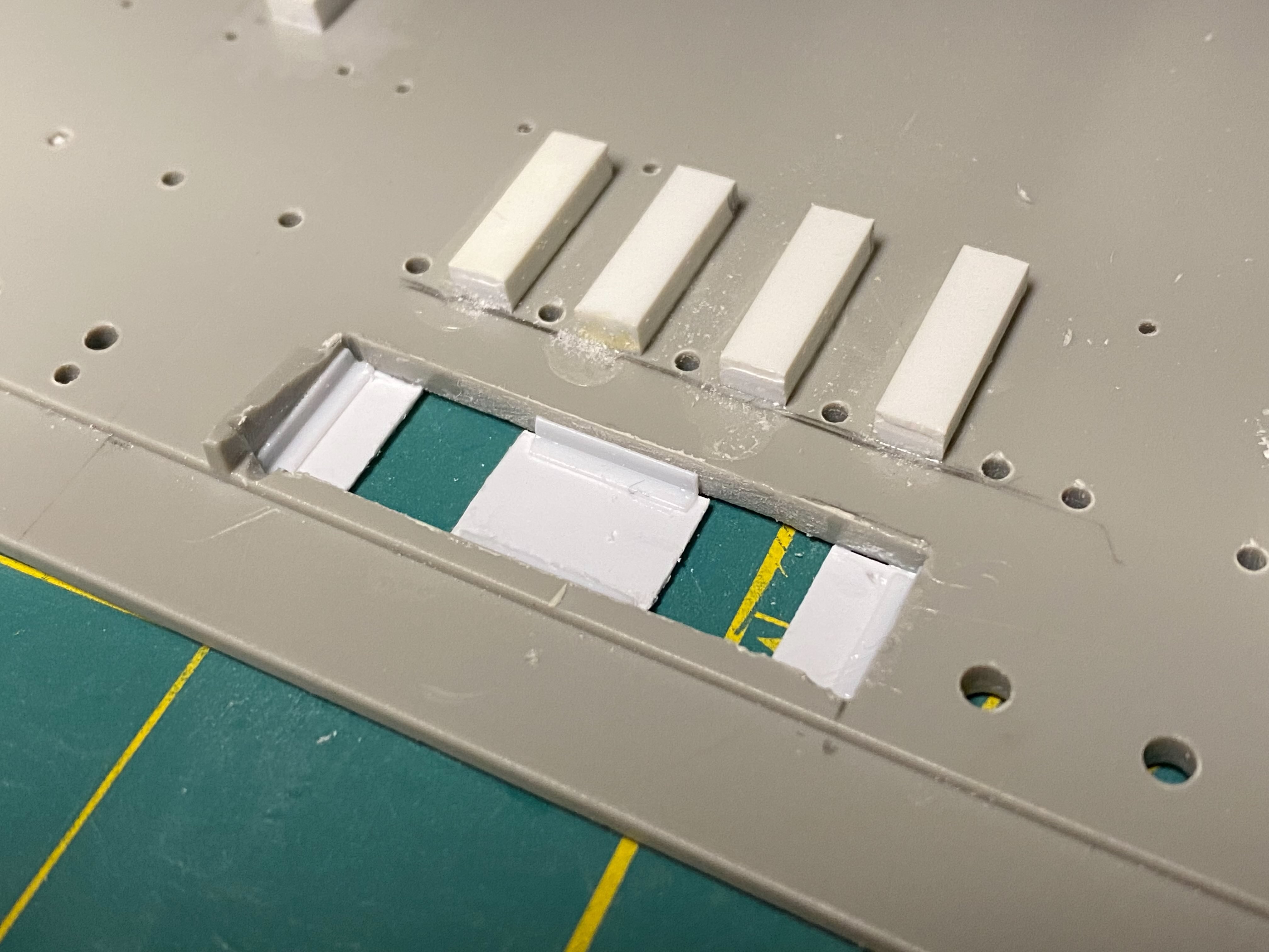
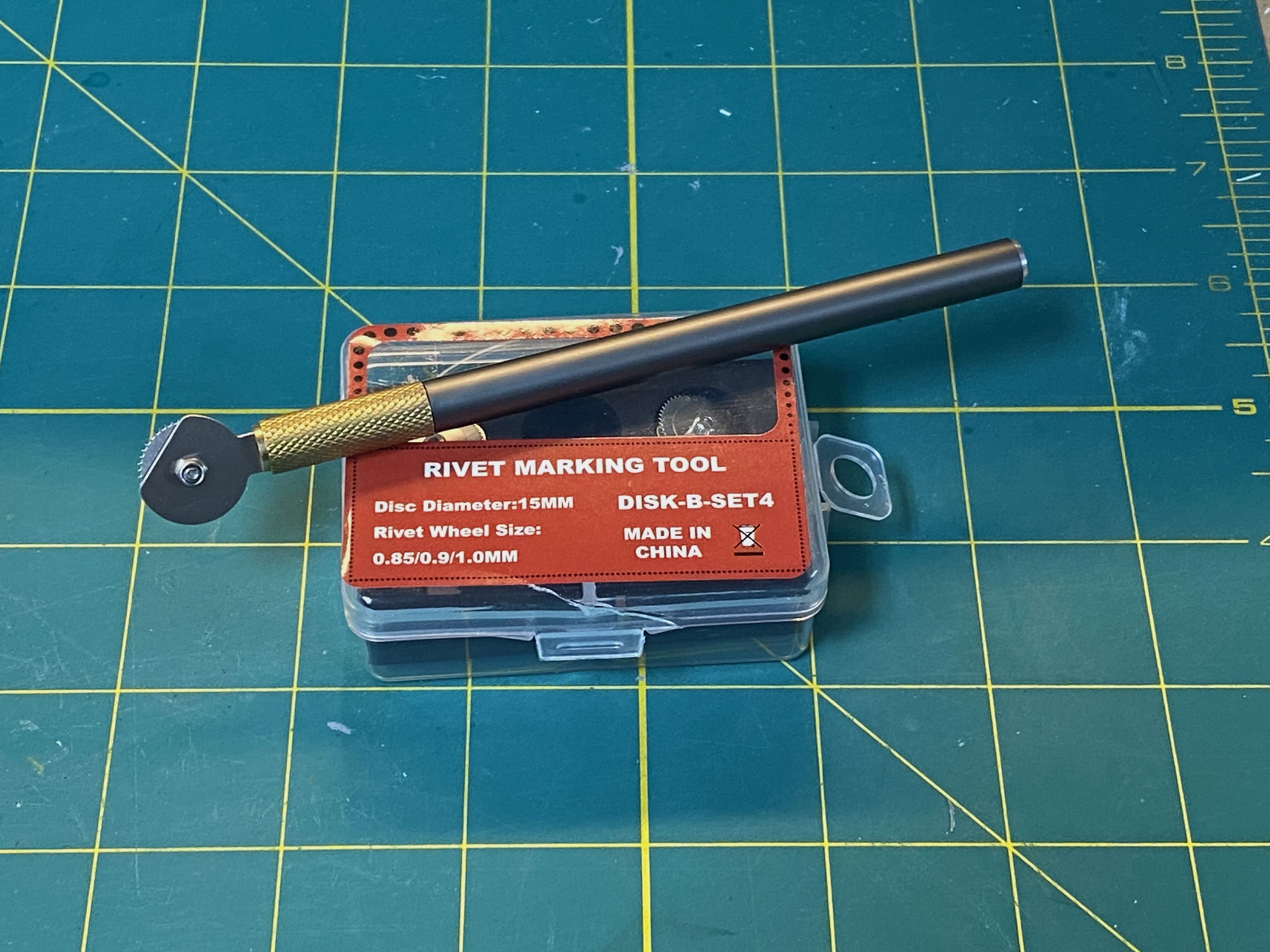
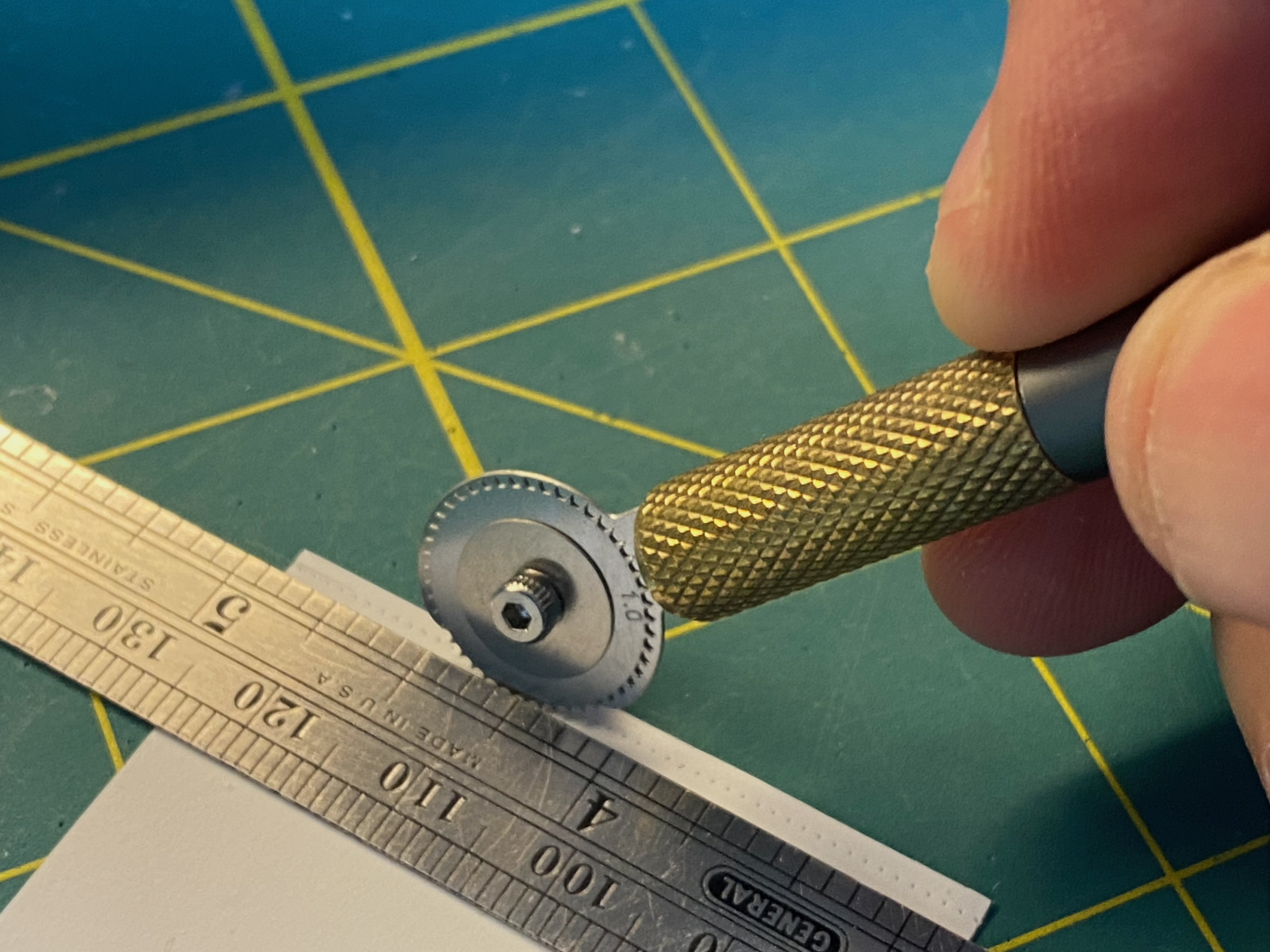
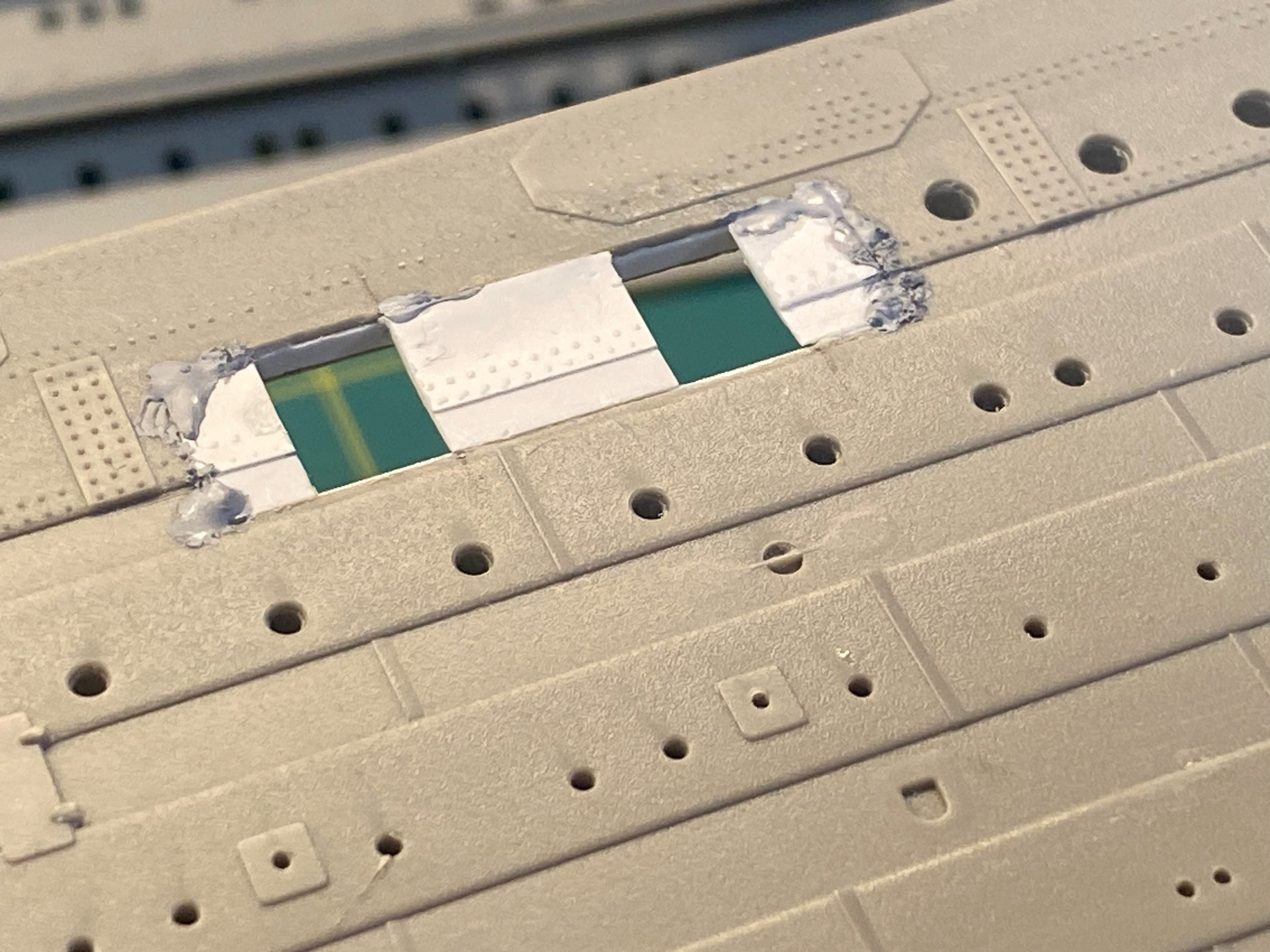
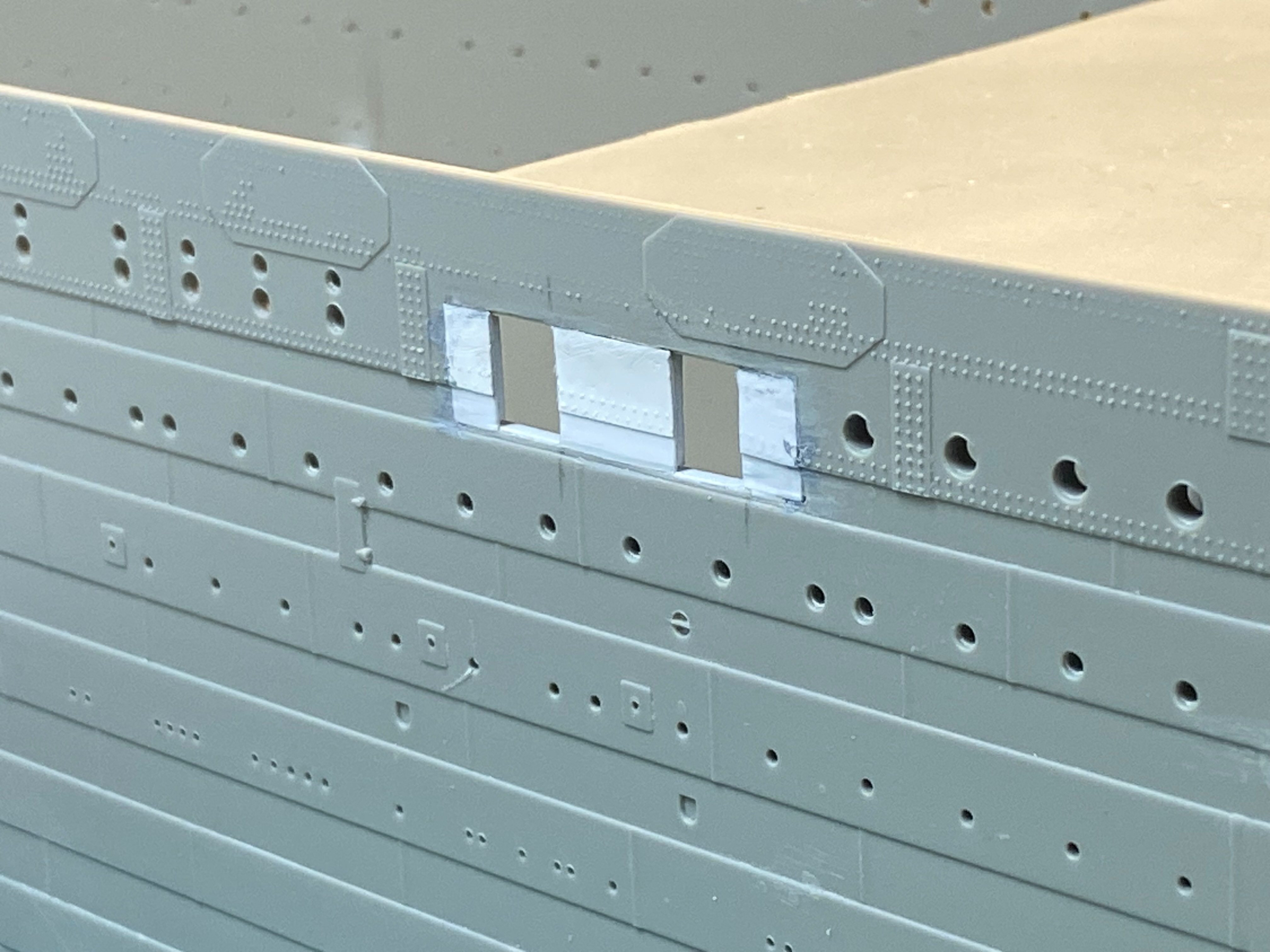
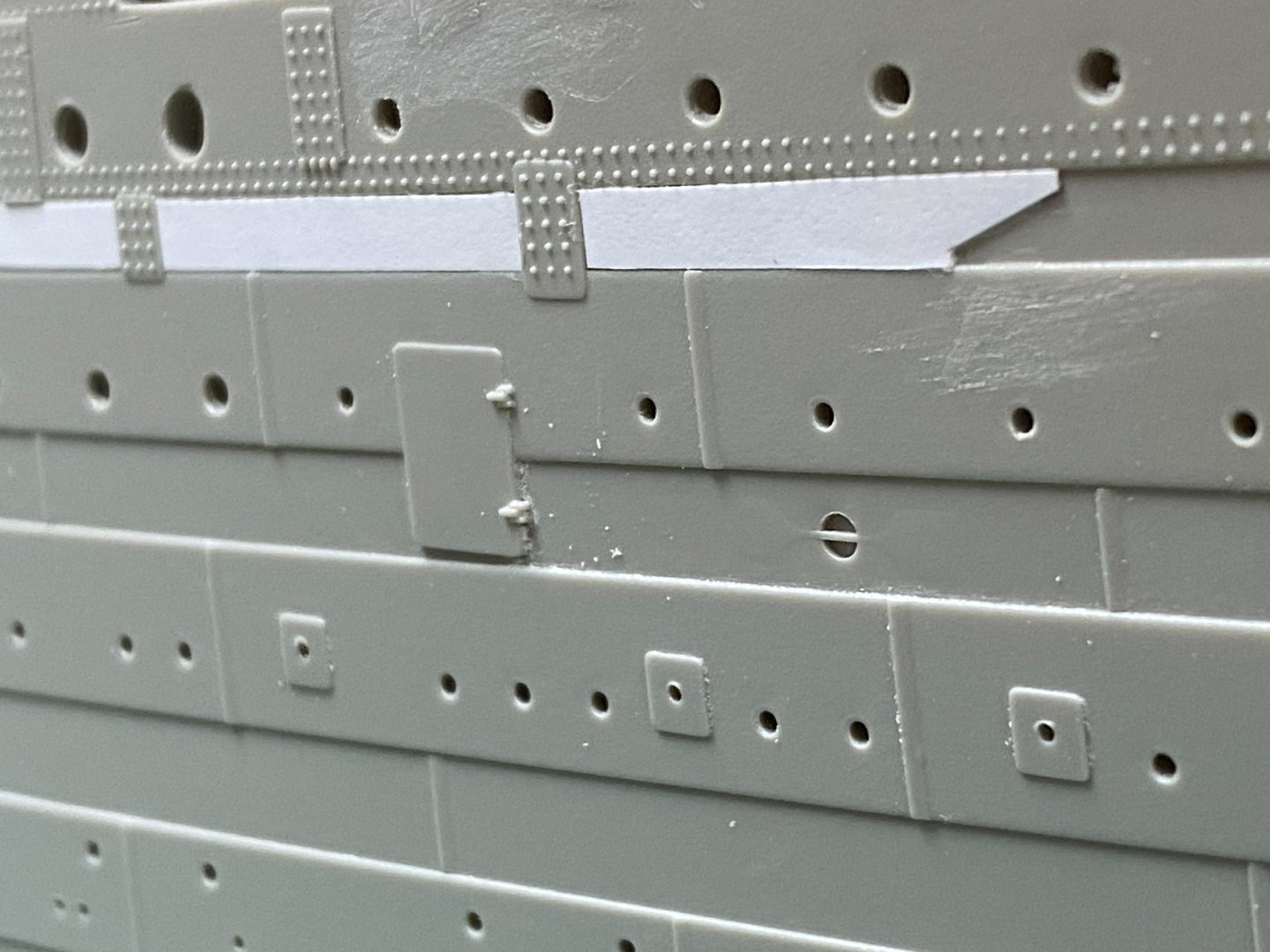
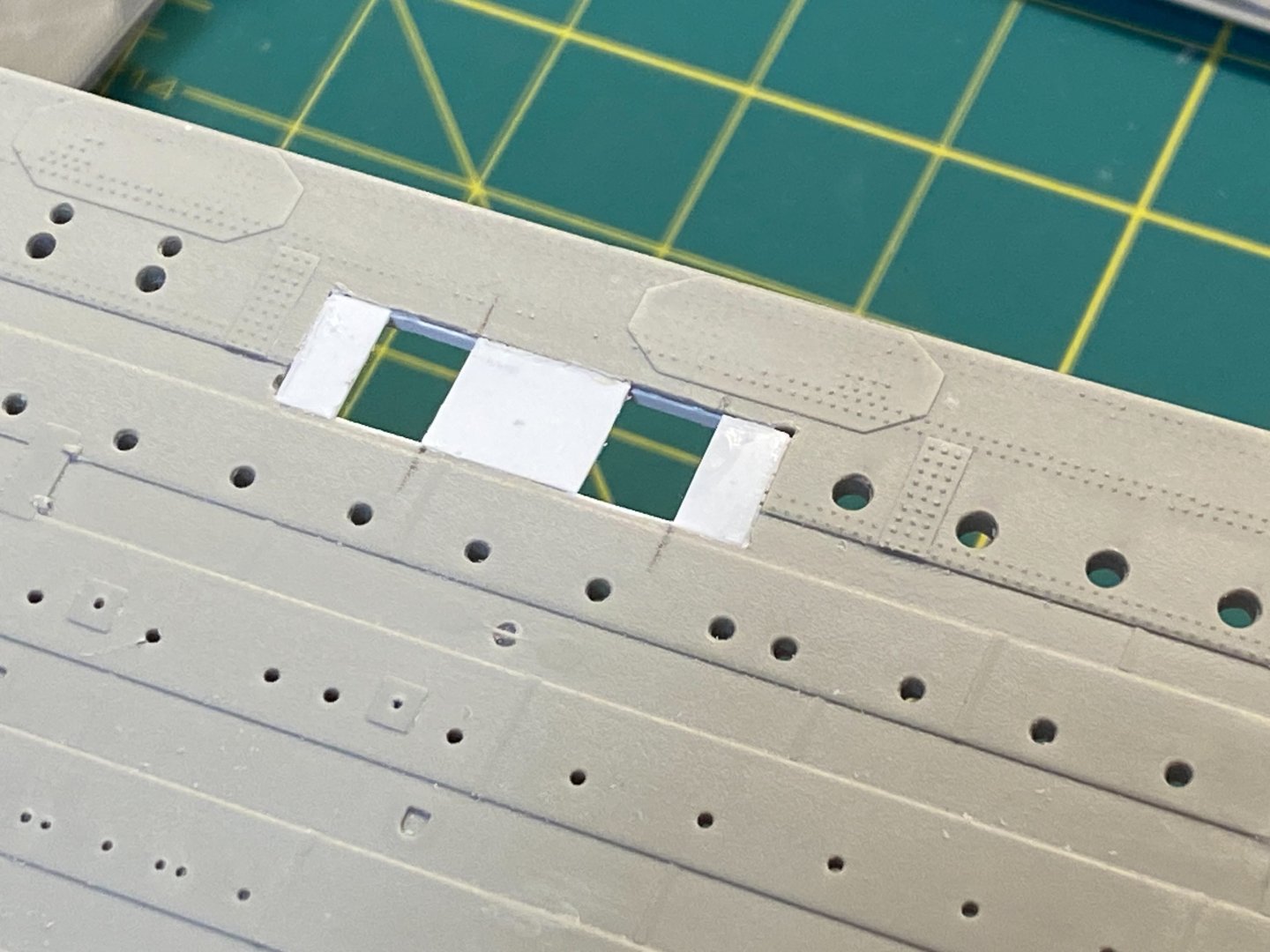
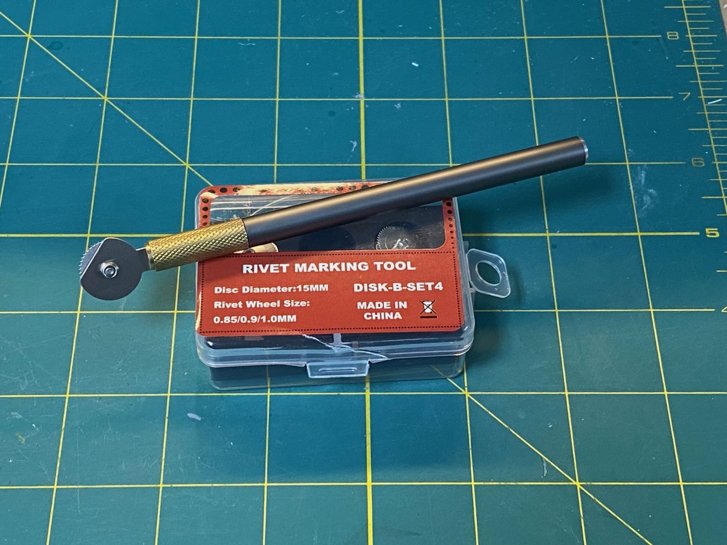
Hello Everyone... The summer heat has abated and I have been able to get back into the garage workshop and work comfortably... I've been busy. Let me start catching folks up on my project... 1st Class Lobby Entry Doors To add more “depth” to the model, I’ll be cutting open various doors and hatches to reveal some of the ship's interior. The first-class entry lobbies are a good place to start. Initially I just opened the doorways on the kit: But this exposed the thick plastic sides… Probably not a big deal for some of the other doorways I’ll open, but these doors have some ornate gates that I’d like to add, and I want to thin things out a bit… So, some surgery is needed. I used a drill to remove the area around the doors (but NOT the top or bottom edges) and filed the edges smooth. Then I carefully matched the dimensions using thin Styrene (.015”) to fill the opening and size the door openings. Everything is supported from behind with some small angle strips: Next, I used a 1.0mm Riveting wheel to replicate the rivet pattern onto the back of .005” styrene sheet and trimmed to match. Flipped it over and aligned the edges to match the kit then glued the .005” on to the underlying .015” elements. The edges weren’t perfect, so some Tamiya putty was smeared into the gaps and filed smooth. Here’s where it stands now: Likely needs some fine tuning after a coat of primer. Cheers, Evan


- 145 replies
-
- 12
-
-
Ahoy Marcus! That is a very interesting observation - a wonderful detail that I'll need to add to my model. Not sure I can add any meaningful speculation regarding the purpose... Perhaps as you suggest it would help to roll barrels or cargo up the side? Hope all is well. Cheers Evan
- 16 replies
-
- 1
-
-
- constitution
- revell
- (and 1 more)
-
Lots of traveling around this summer and the garage workshop has been too hot and stuffy to get much done in between... I have made a bit of progress and I'll catch everyone up in a few weeks. Stay tuned! Cheers Evan
-
Ahoy Mark! Catching up on your outstanding progress... I bet you're thrilled to be past all of the portholes! That guidance provided by Mr. Boyd is soooooooo helpful. I'm excited to see this build log and especially interested in the MidWest Model Shop additions on the stern counter. I think using Ben's styrene version makes a bit more sense than going with the Mini-Brass. Hopefully you'll be pleased with the result. Thank you also for the kind remarks in your intro - I do hope my build log helps others to get a running start. (as will yours!) Cheers Evan
-
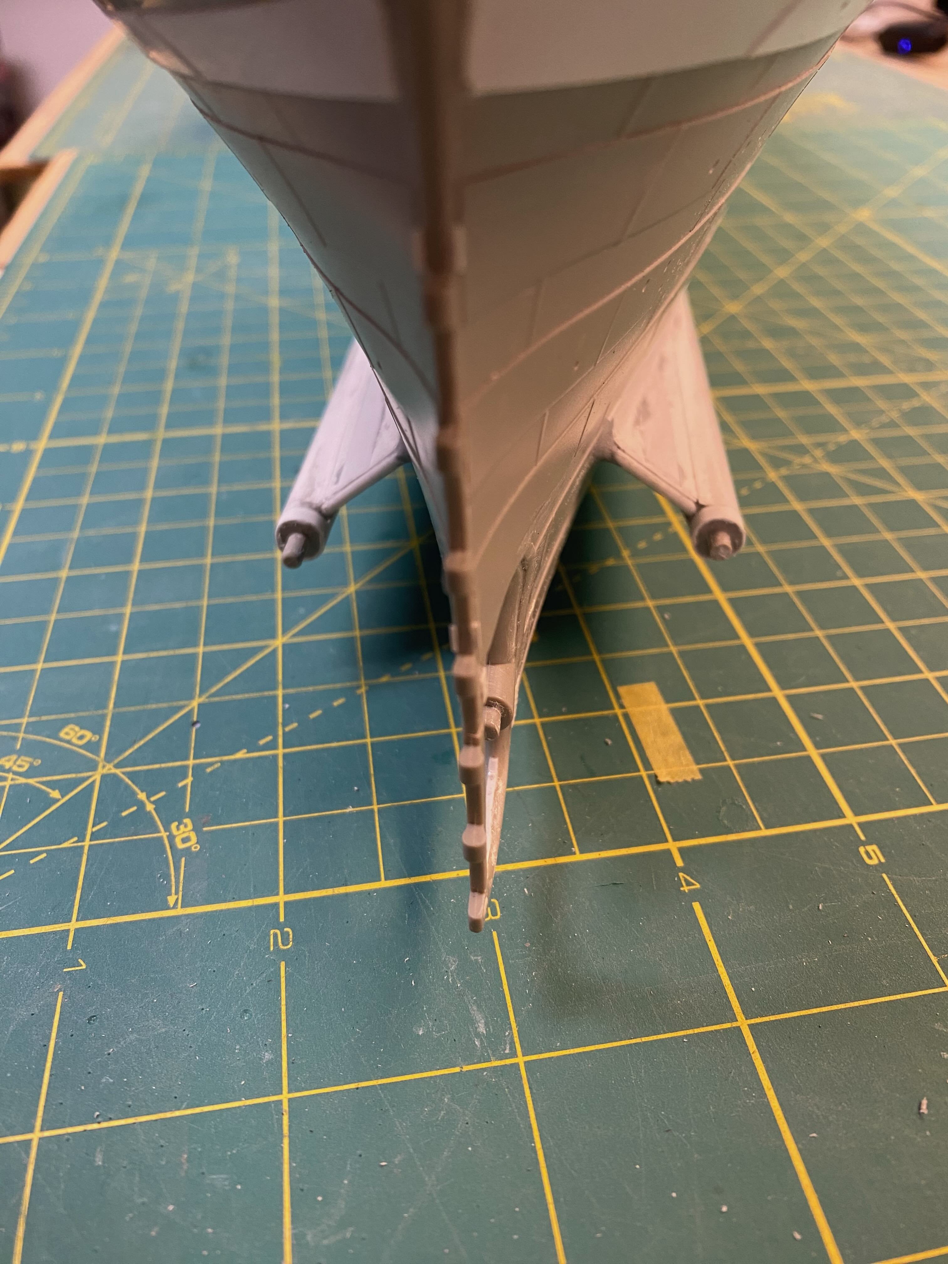
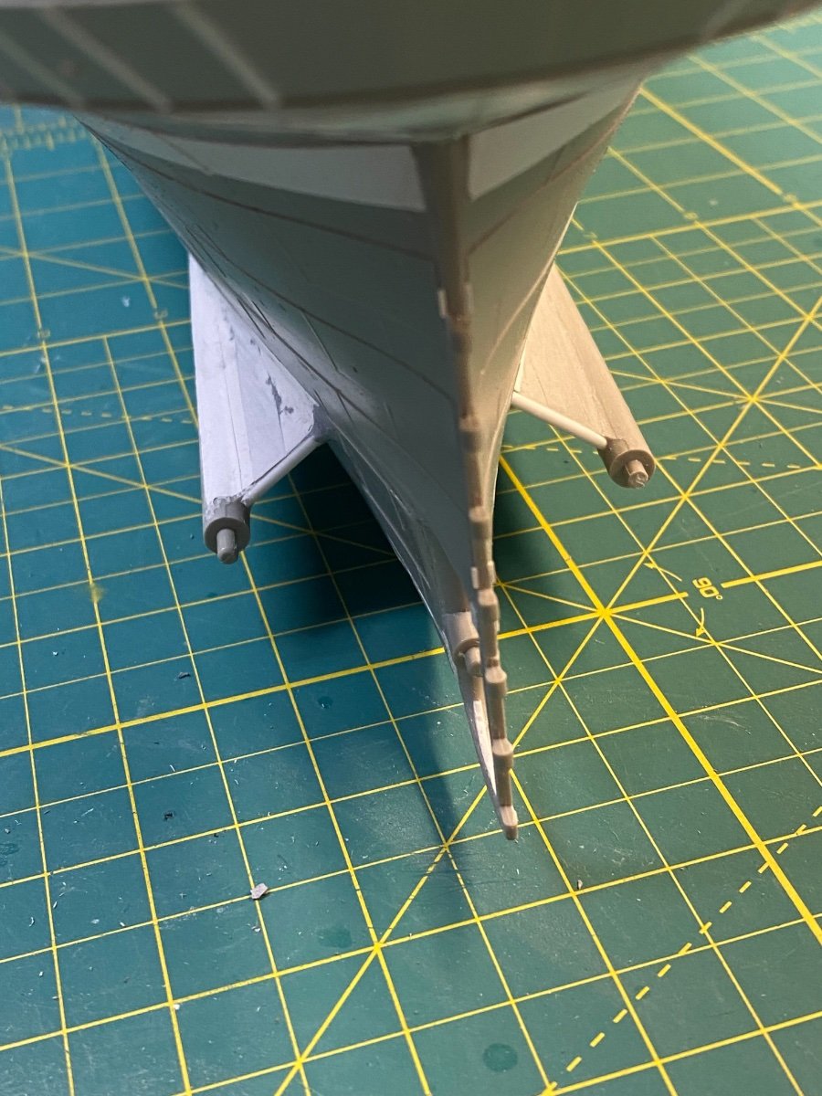
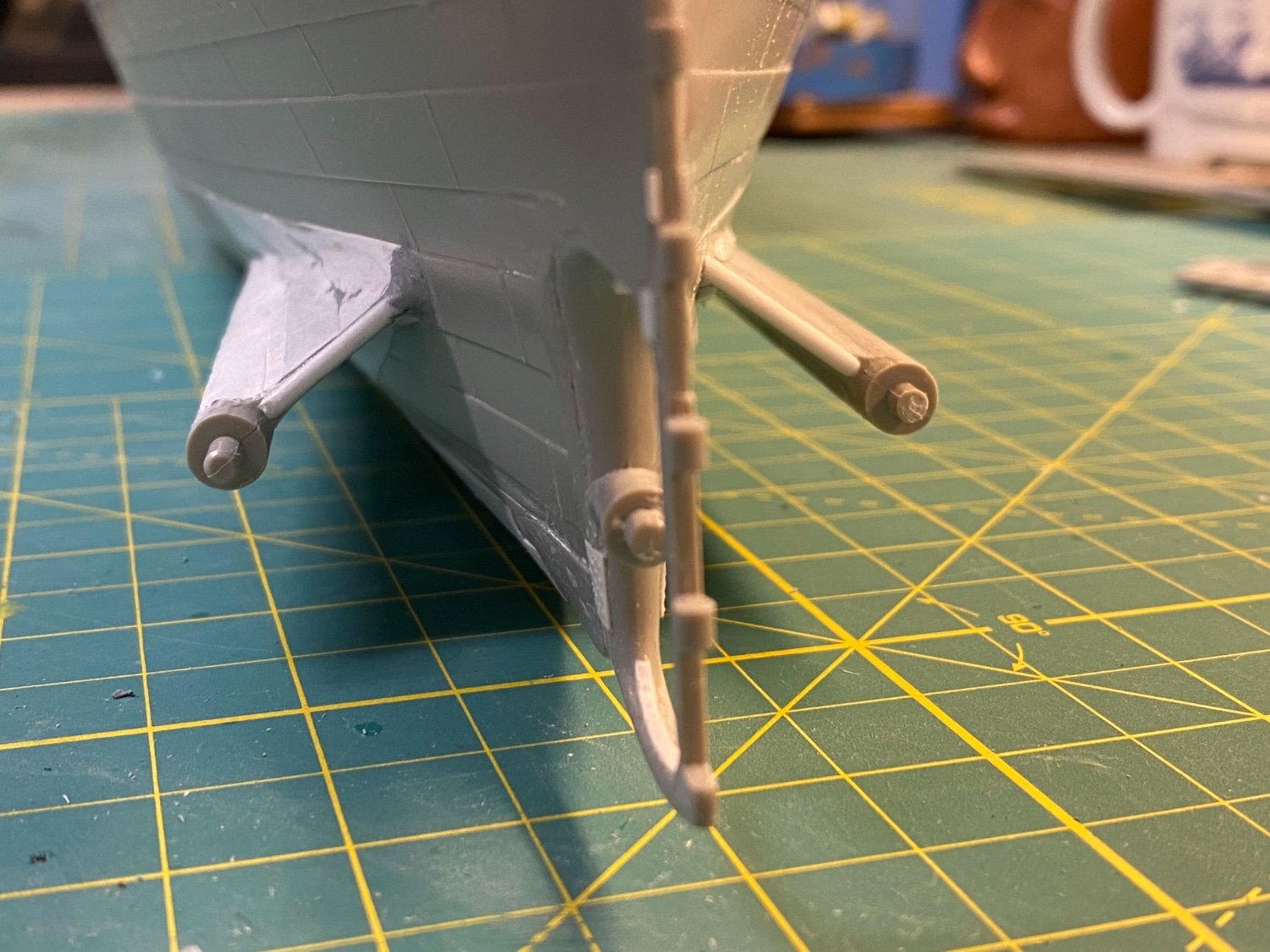
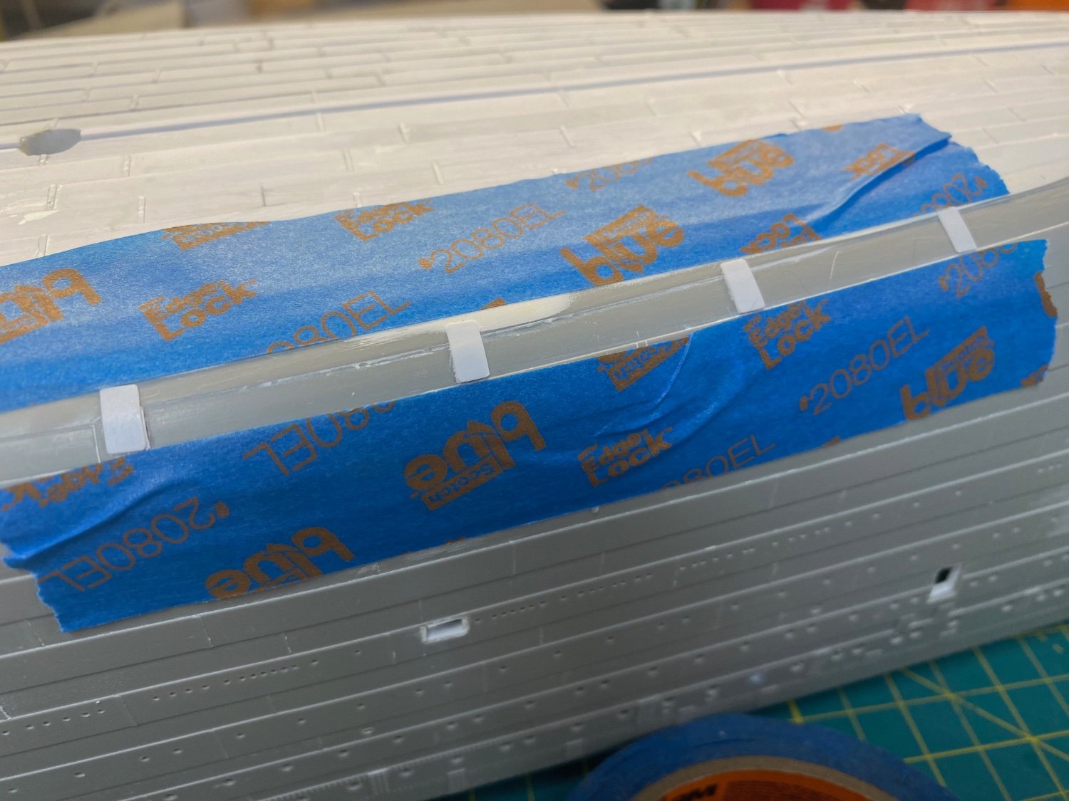
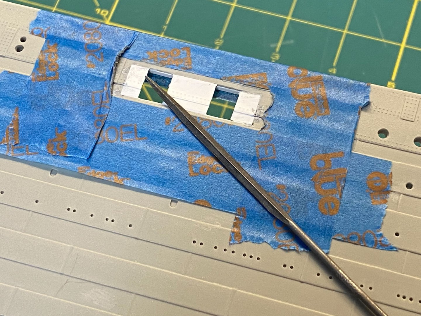
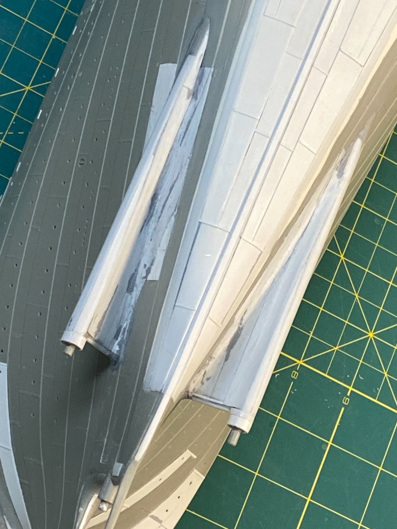
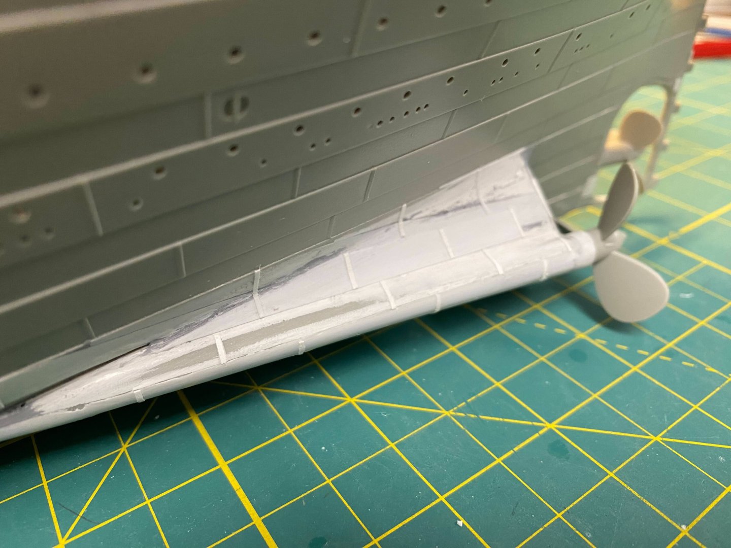
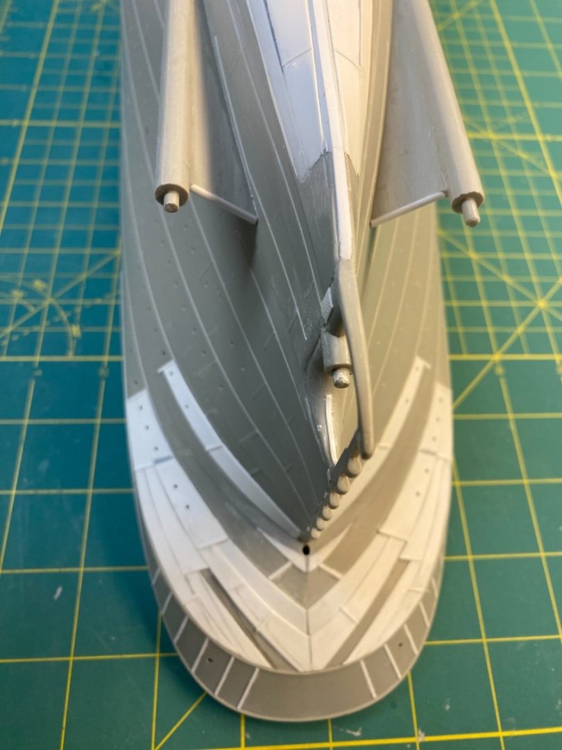
Apologies to everyone for the long delay… I spent some time across the past few months working on my US Frigate Constitution model along with a bunch of travel (including to the other coast for my daughter’s college graduation) that kept my Titanic on ice (so to speak). Let me catch you up. Propeller Wings Continued… There was still some styrene to add to the propeller wing surfaces. The top and bottom wings are now completely covered and additional styrene was bent and glued around the prop shaft/boss outer surface. Added some thin strips to represent the plate overlaps in the same manner as the underbody hull plating… Used Tamiya tape to make a template to help guide similar placement on the starboard wing to make sure it all looks equal from the stern. I won’t be utilizing the kit provided propellers, but why not slide them on to get a quick perspective with everything in place? Next up I’ll highlight my initial effort to thin out the sides of the hull around the open first-class lobby entry doors to better match the scale. Cheers, Evan
- 145 replies
-
- 12
-
-
-
Hello Jeff - You have an incredible Mikasa and your approach to her presentation looks promising. Difficult, I'm sure, to get a smooth cut to match the hull contours...! Cheers Evan
-
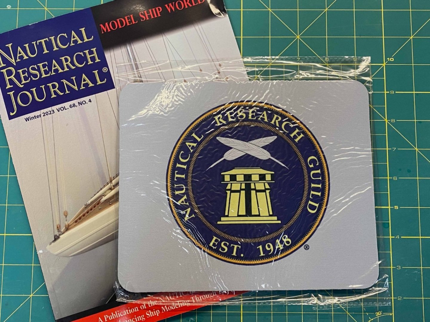
@LAHF1 Ahoy Loni... Thank you for popping in... I appreciate your interest in my Titanic. I hope you consider adding your perspective in a build log or some other format. I find that keeping some sort of log helps me to organize my approach and maintain the long view needed to make progress. Hope you had a great holiday season! @Jeff59 You have a great start on gathering some terrific enhancements for the Trumpeter kit... Good stuff. I'm being cautious about how much investment I need to make on 3rd party add-ons. At some point they can detract rather than enhance... I'll try to focus on acquiring elements that solve for issues that I can't otherwise handle with some scratch building - or at least gain significant time advantages. Model Monkey is a terrific resource - I've utilized some MM 3D prints for my Old Ironsides build. Certainly the Titanic funnels are on my radar. I do hope that my build helps with your efforts in some small way... At least serve as some sort of inspiration. @NavyShooter I checked in on your Titanic... That is a big boat. Impressive 3D printing - must've taken days to generate! Thanks again for looking in on my build. @Roger Pellett Please let us know if Naval architects do discover the necessary engineering needed in order to sailor proof anything that floats. @md1400cs I'm happy you found your way here... I suppose at some point I'll have to admit that I'm immersed enough in all of Titanica that I'm another in a long list of Titanicphiles... A fan. She is a beautiful ship and the circumstances of her end makes for compelling research in my quest to enhance the kit and move it closer to an accurate representation. To that end... I'm gonna double down on the research side of the hobby. I've decided it was time to join the club: I'm now a proud member of the Guild and have already benefitted from my first Journal issue... A great overview of a FFG build that will inform my own (eventual) kit build... An older brother served on a Perry class frigate while escorting tankers during the Persian Gulf war. Cheers Evan
-
@Roger Pellett Ahoy Roger... The book has some fascinating insights and I am learning a lot that isn't included in the normal fare that we all consumed about the Titanic over the years. I will PM you regarding the email insights. I do like the professional assessment that Naval Engineers provide about the Titanic disaster... Sure, the rivets varied in relative tensile strength and the cold temperatures of the North Atlantic may have played a part in their failure... There was a smoldering fire in a coal bunker that may have weakened the nearby bulkhead and made it vulnerable to hydrostatic failure... But ultimately the Titanic was state of the art and built to the highest standards available in that era. After extensive research and recent insight I've unearthed the TRUE reason for the tragedy of the Titanic... Psst (in whispered tones)... While steaming along at over 20 knots she sideswiped an iceberg in the North Atlantic. The rivets would've failed regardless... The internal bulkheads would ultimately fail to protect her regardless... No level of 1912 era technology would've saved her. Sure... Plowing straight into the berg might've kept her afloat with massive casualties in the forward section. But nobody then or now should advocate for Murdoch to have made that choice. I should include this stuff in my YouTube log! Cheers Evan
-
@dvm27 I am familiar with the terrific YouTube series that Ben (and Nora) put together for the Trumpeter Titanic... I especially appreciate that he acknowledge his mistakes (that we ALL make) along the way and showed his recovery process. His outline of all of the 3rd party options is extremely helpful. There are other great YouTube logs for the kit and I'm not certain that the world needs ANOTHER one... But I hope to bring a fresh perspective. In particular, I'd like to emphasize the enhancements and various corrections that I'll be including in my build to move it closer to a more accurate representation of the ship. As you've seen in my build log here, I'll also include background on my research wherever applicable... I'm not sure that what I've seen so far in the Vlogosphere does a complete job of showing WHAT is being done, HOW it is being done, and WHY it is being done. This'll be important in my YouTube approach to illustrate my scratch build elements - a key difference from other YouTube logs to date. We'll see if I can pull it off. @patrickmil Aye Patrick This group will be the first to know. I don't think I'll publicize my channel beyond this space for a few months until I gather feedback from you all... I'll always update my build log here first... It'll help me organize my thoughts/approach for my YouTube versions. Cheers Evan
-
@Roger Pellett Look what I finally found! Your book recommendation started to seem familiar to me... I searched all over for it. Turns out my daughter had it with her at college! Demonstrates her interest in all things Titanic related... I now have it bedside and am reading several chapters a night... Fascinating stuff. Great to get the perspective of Naval architect types. In the meantime... Folks - I apologize for the lack of updates. I've been stalling while I consider adding a YouTube series about this build. I need to build up the necessary equipment from scratch so I've petitioned St. Nick to add some packages under the Christmas tree. There is the sticky matter of being a "Good Boy" this year... I've done a back of the envelope calculation and I'm optimistic that on balance I have a net positive rating across the year. In the meantime, I'm getting up to speed on video editing. Stay tuned! Cheers all Evan
-
Ahoy @Niemand... Apologies for missing your note. Many thanks for the kind remarks - I really do appreciate folks stumbling on my build and finding some value... As it happens, I've started working a few elements on this project. I am hoping to get the halves fused together with the gun deck in place along with the rudder and stern details. I'd like to have it set up with pedestals mounted on a wooden plinth in the near future. Cheers Evan
- 446 replies
-
- 2
-
-
- Revell
- Constitution
- (and 1 more)
-
@GGibson Hello Gregg - Thanks for the compliment... I hope my efforts have some value to other Titanic builders and hopefully you'll reconsider and put your Titanic into the builder's yard. Cheers Evan
-
@Paul Jarman Thanks for the note... It seemed to me that there were a million portholes as I was drilling them out... Gawd forbid I have to add the rivets!!! I popped in on your build - great to see a wood kit that lets you construct a much more accurate hull underbody. @richardhd Thank you for popping in too. I appreciate any encouragement. I suspect you're not the only lurker... Unless 7 people are clicking on my build a thousand times each. I'll say that this kit can never be 100% accurate - but I will try to move things a bit closer to the historic ship where possible. Most purists would probably not take this on because of the discrepancies - or abandon ship midway thru in exasperation. Don't hold your breath awaiting paint... I'll likely put off painting the hull as long as possible. It'll become a much more fragile thing that will be susceptible to scratches, blemishes and dust... I'll avoid those risks until I absolutely have to apply paint in order to proceed. Thanks to all for the Likes and the patience between updates. Cheers Evan
-
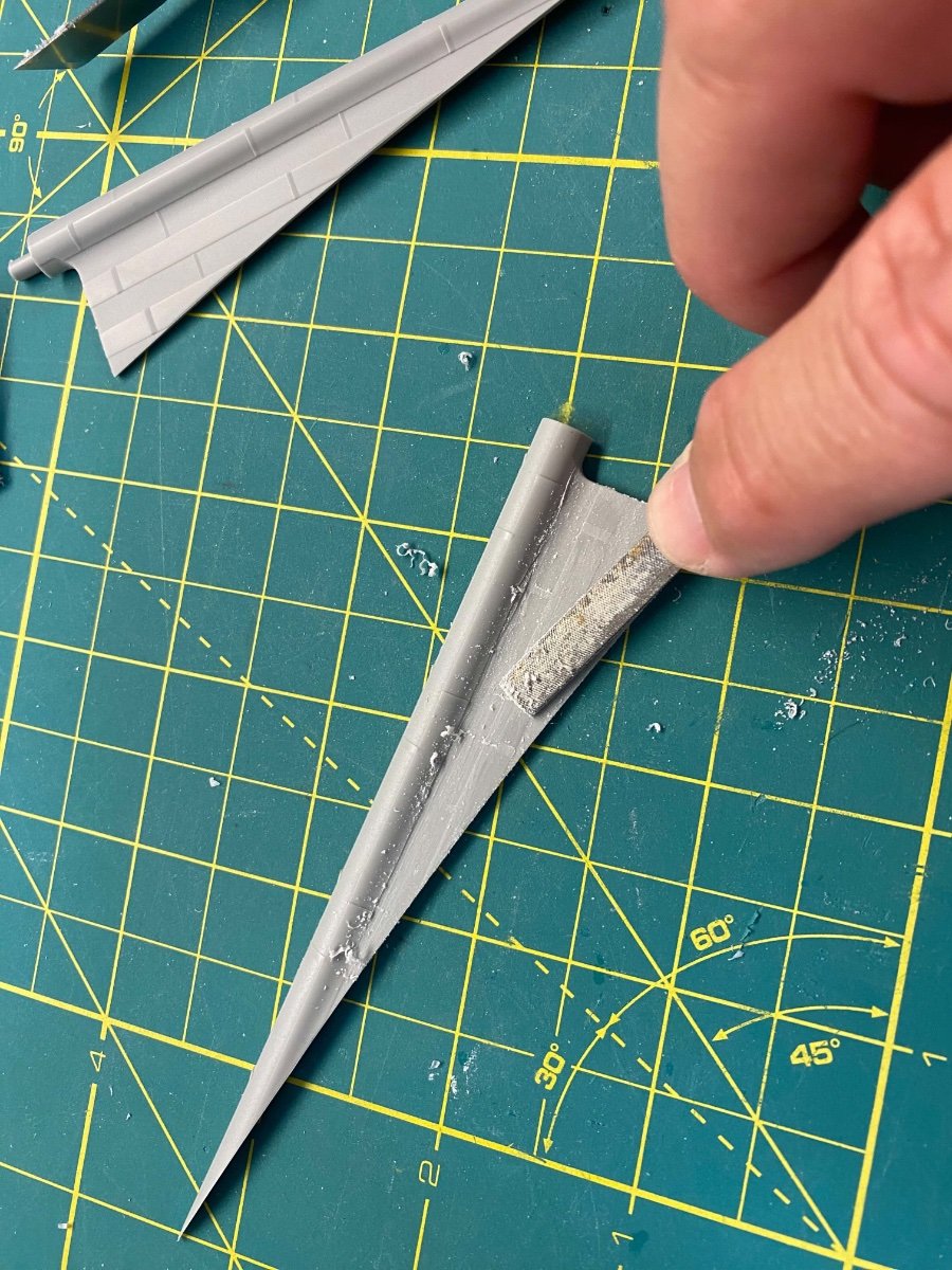
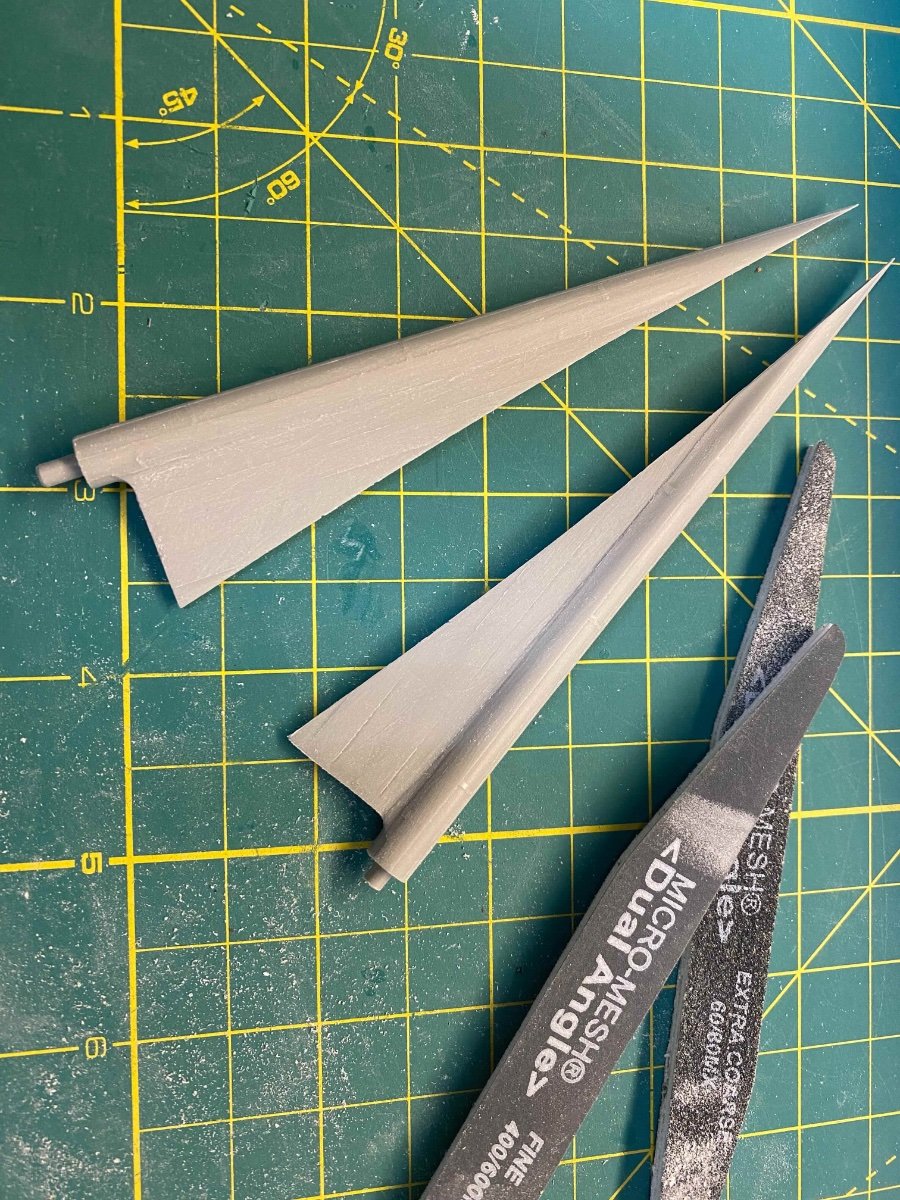
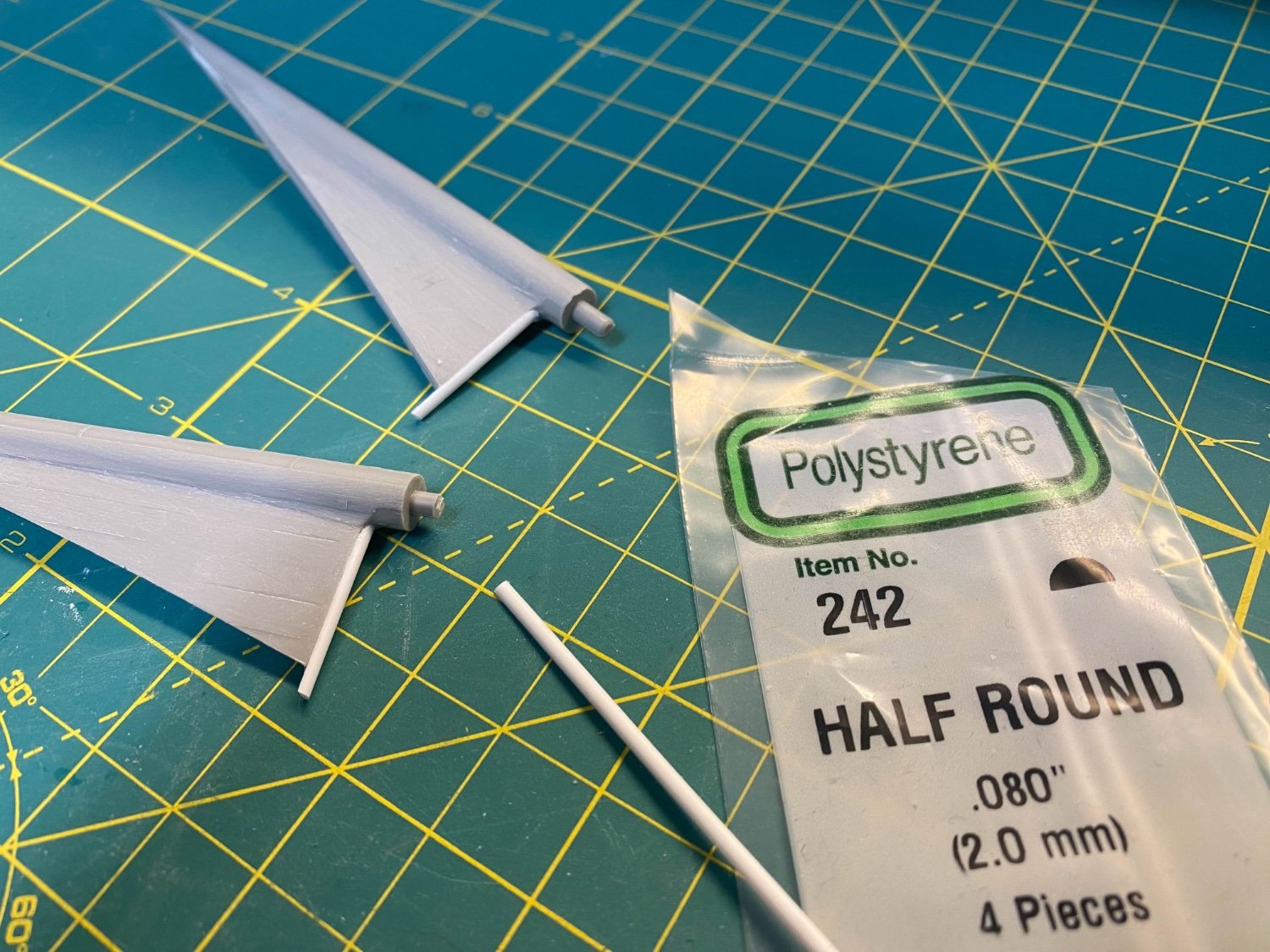
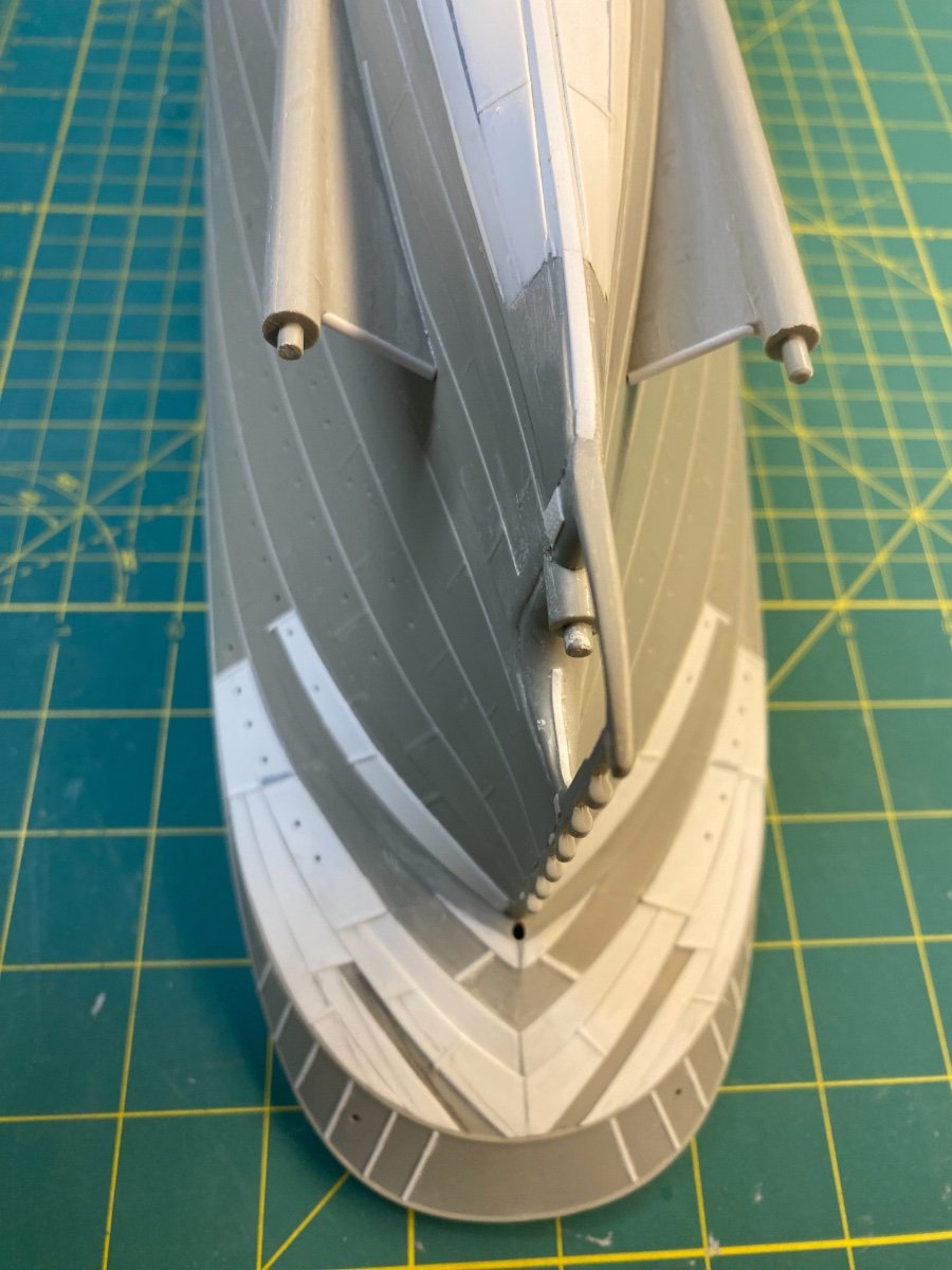
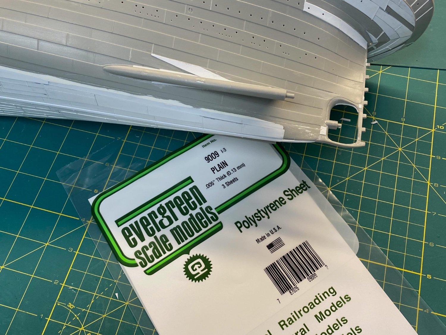
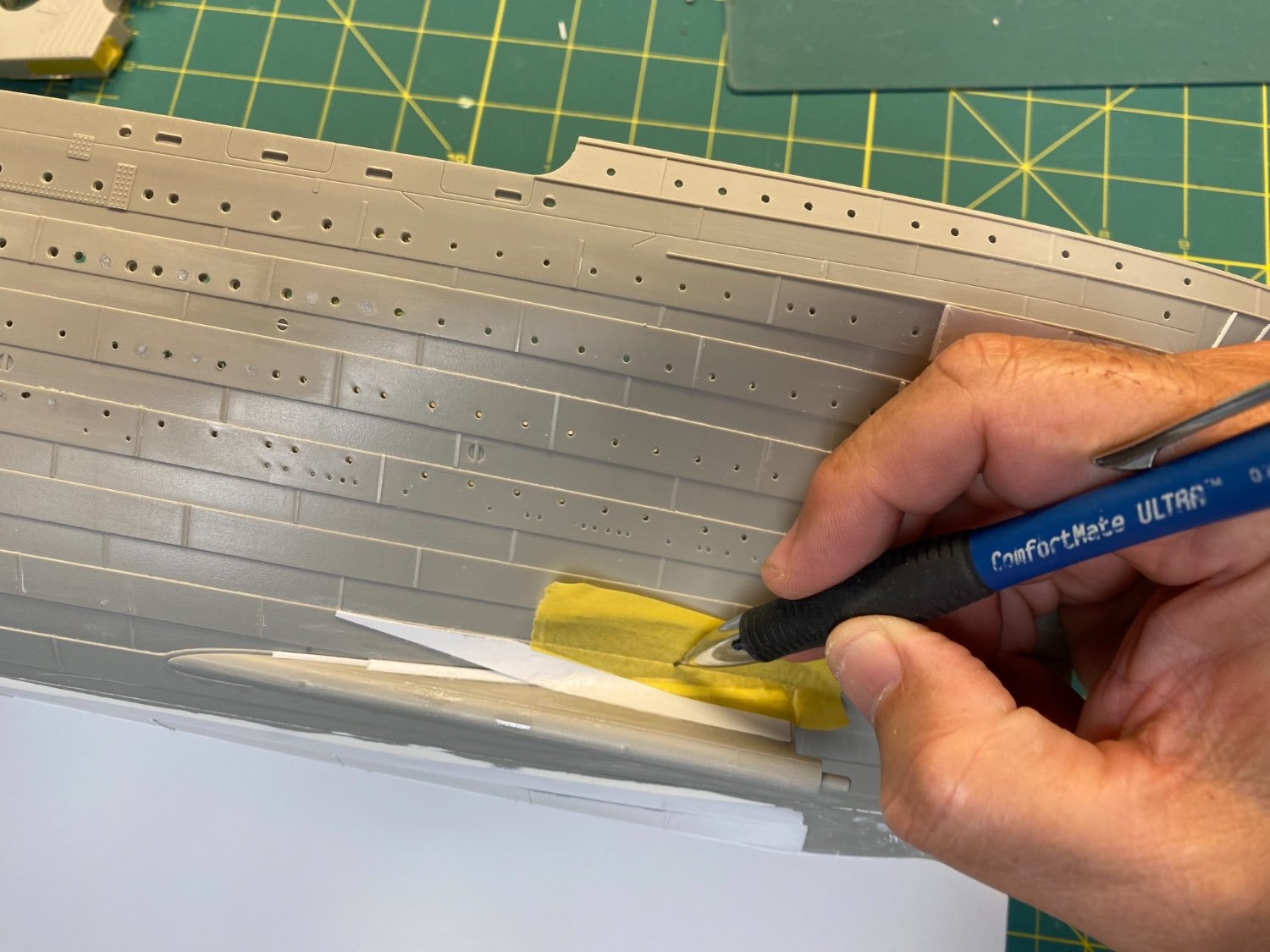
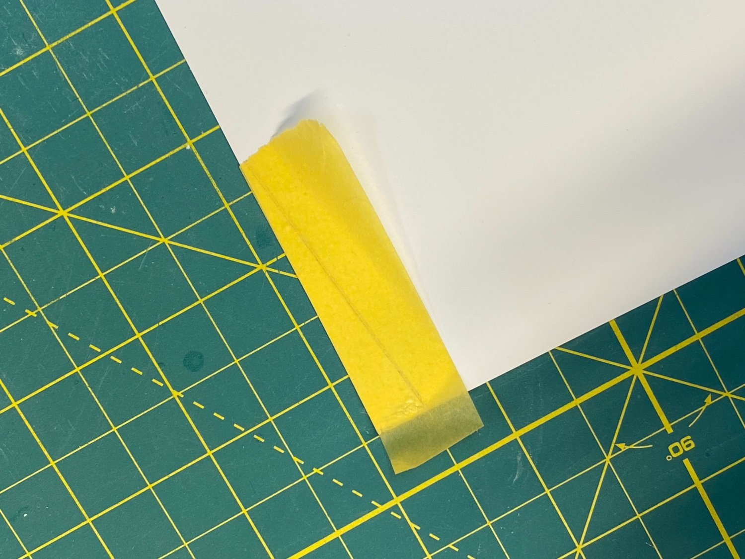
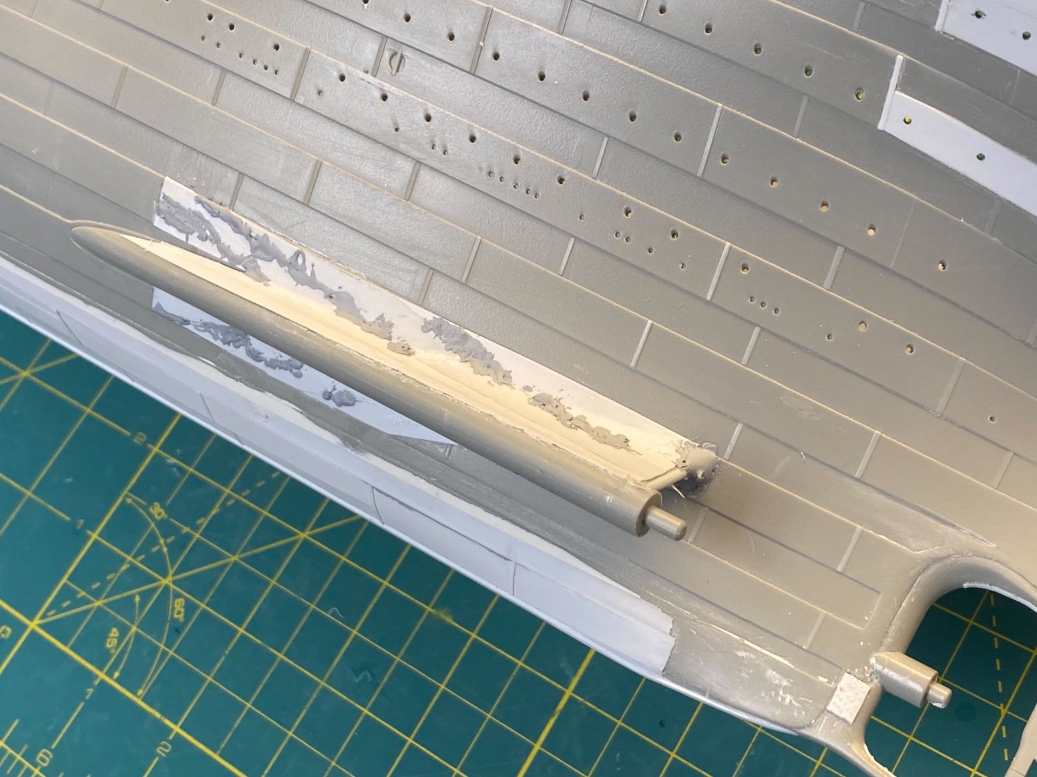
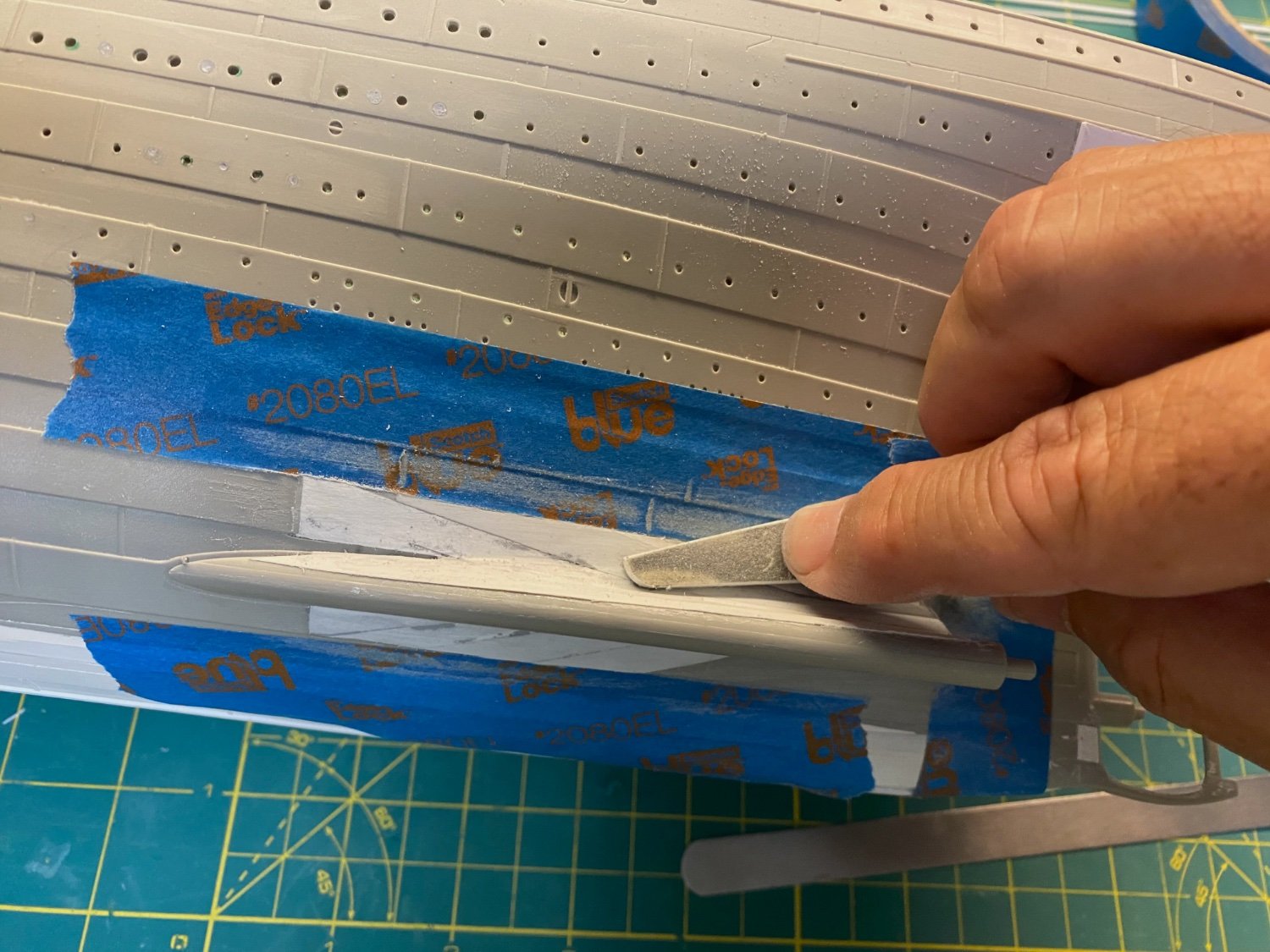
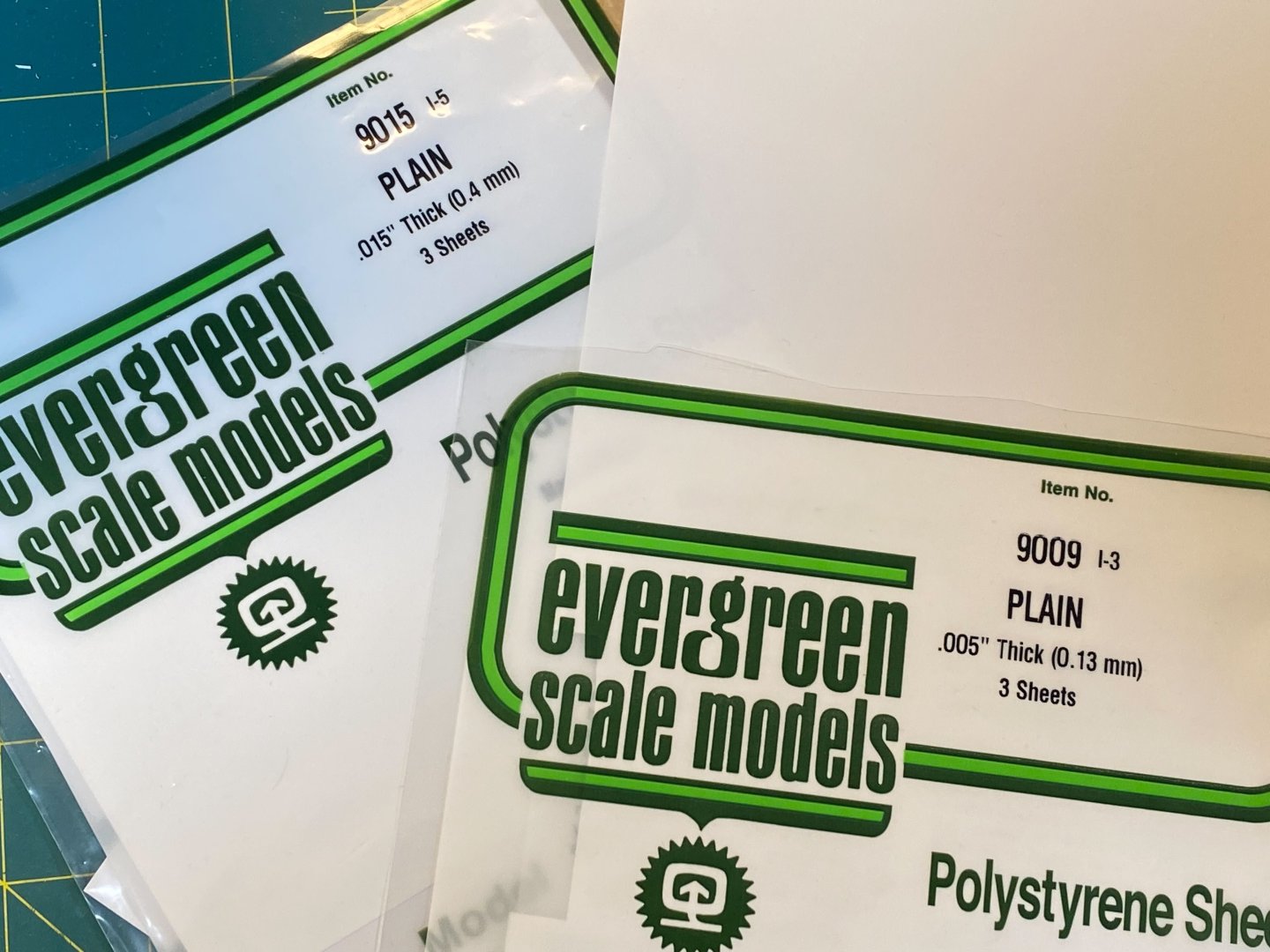
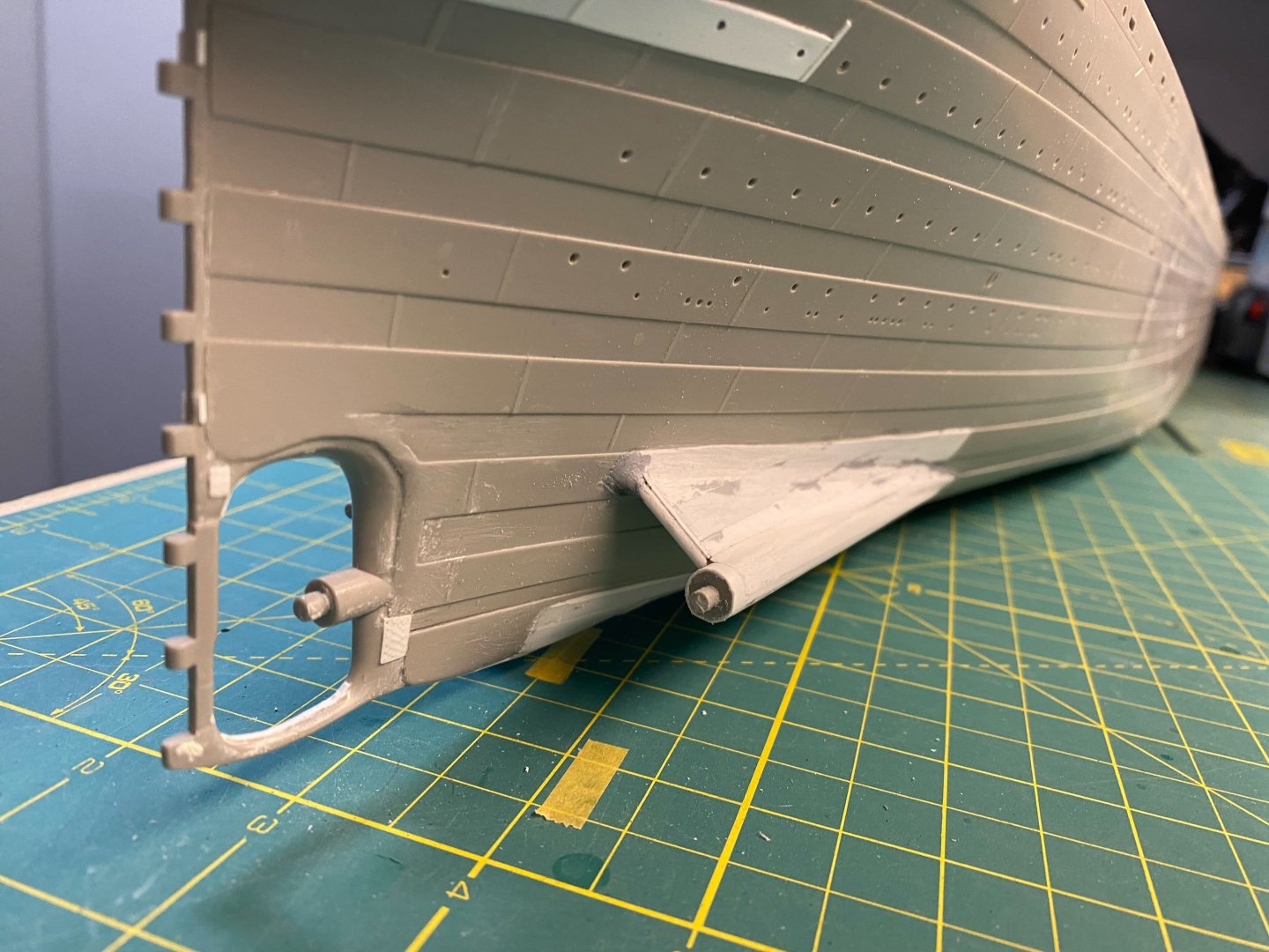
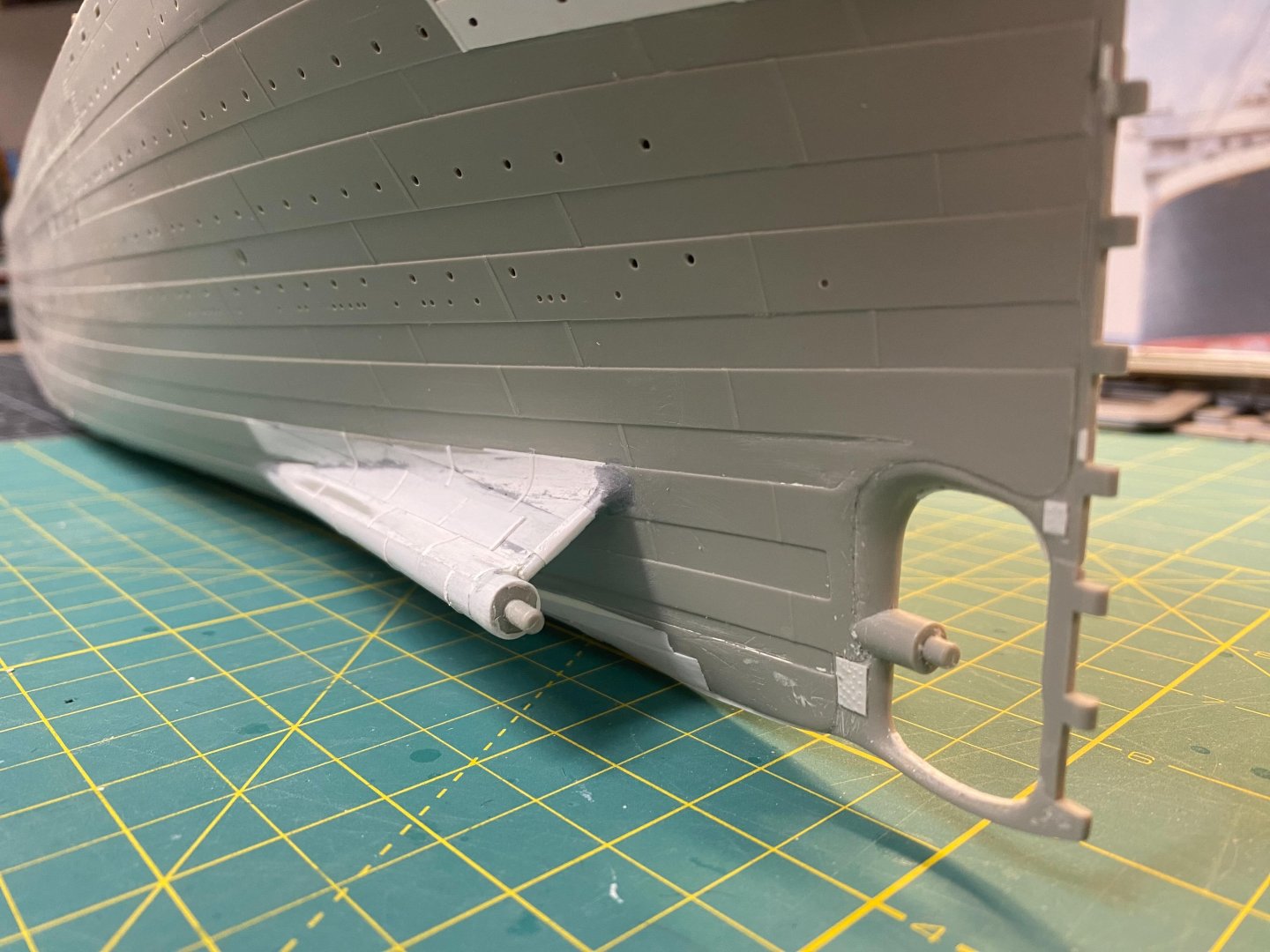
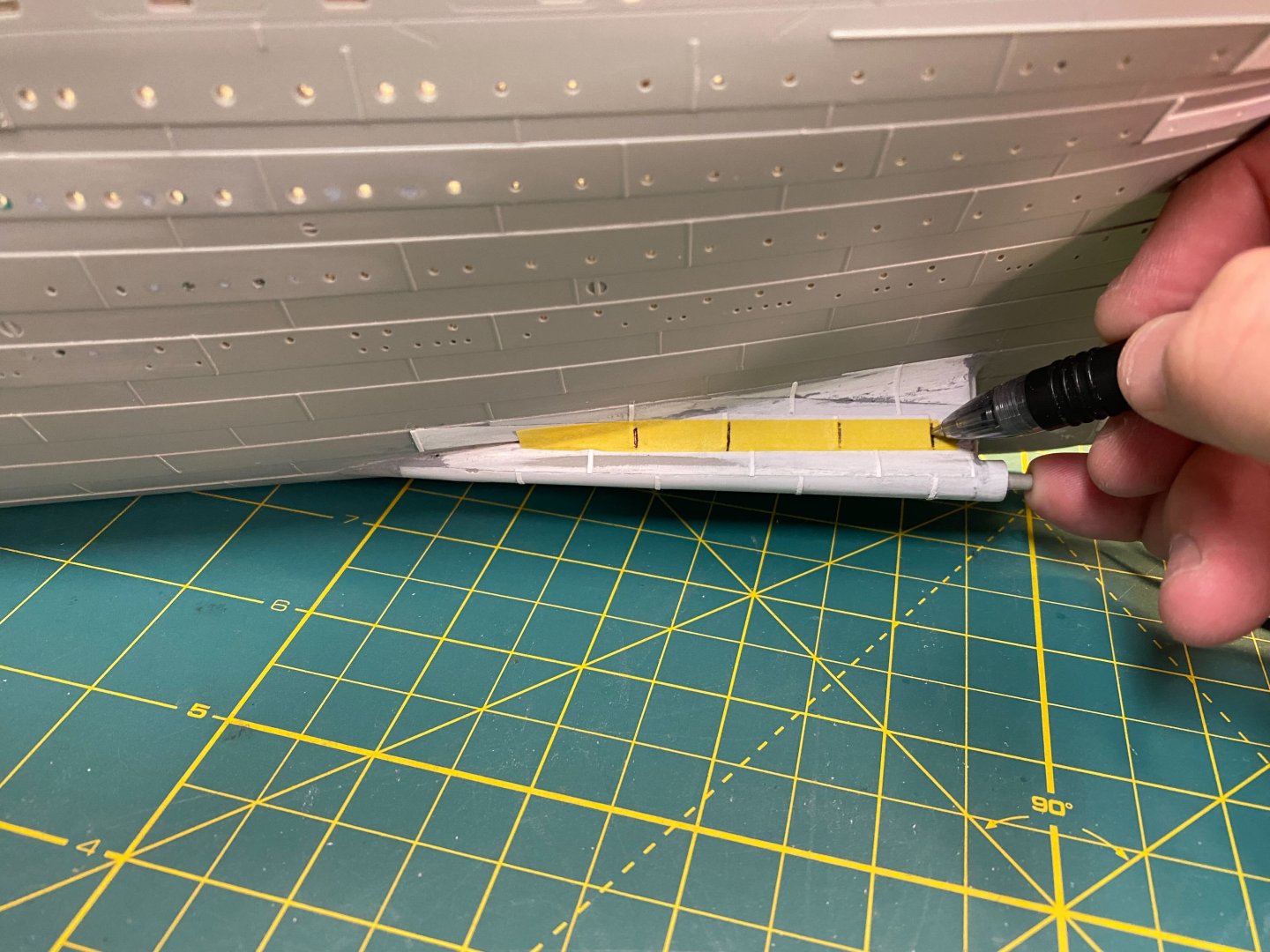
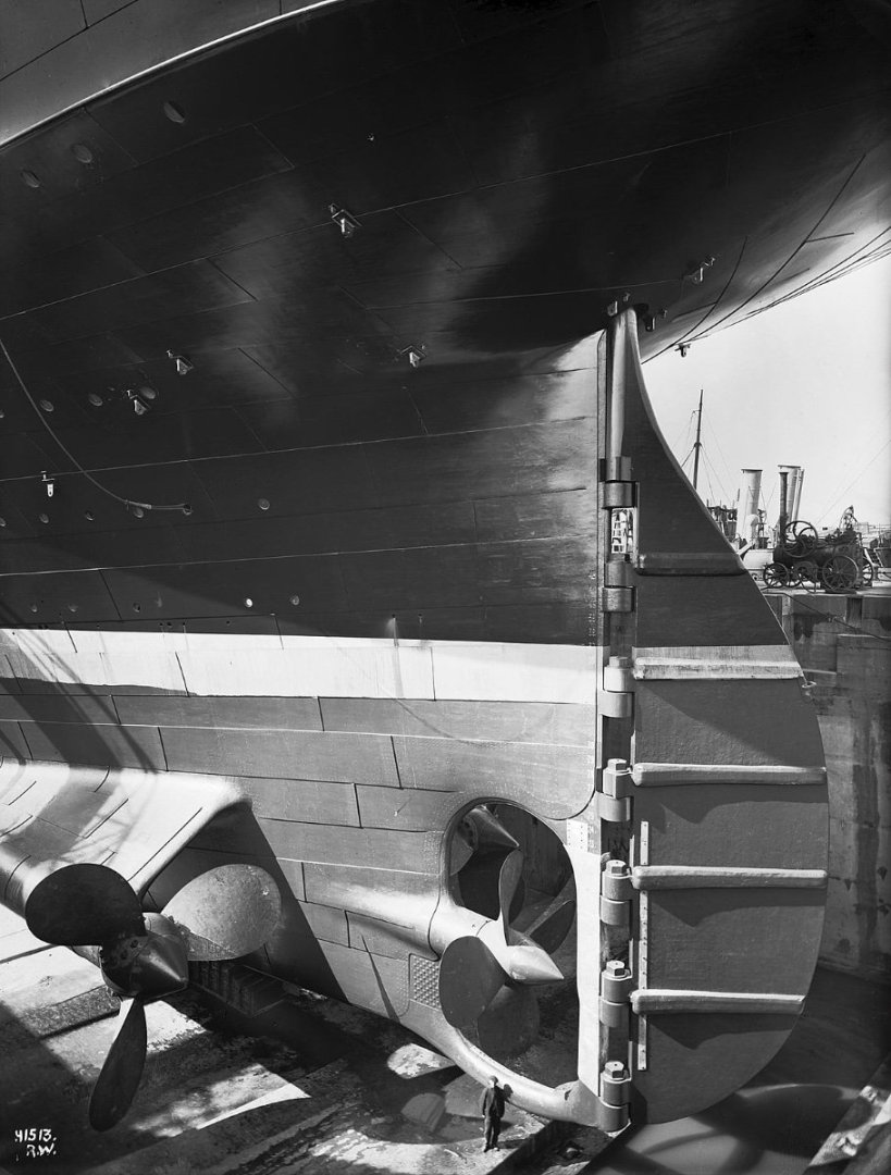
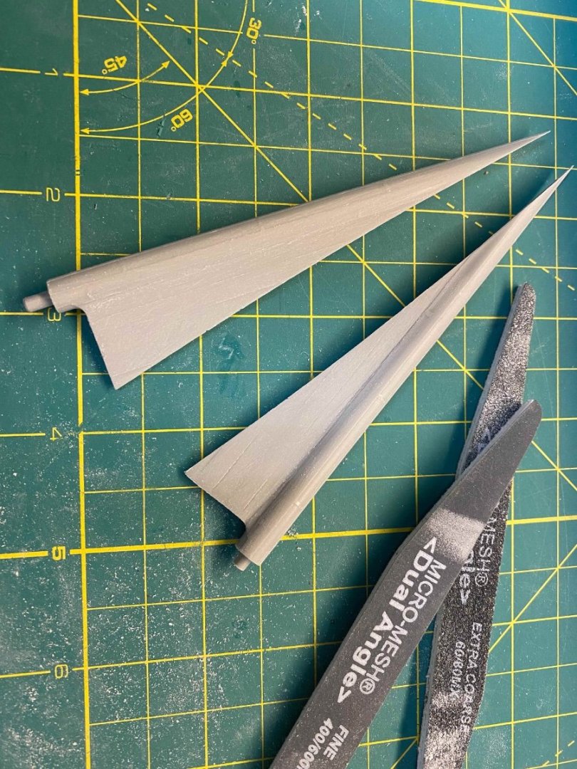
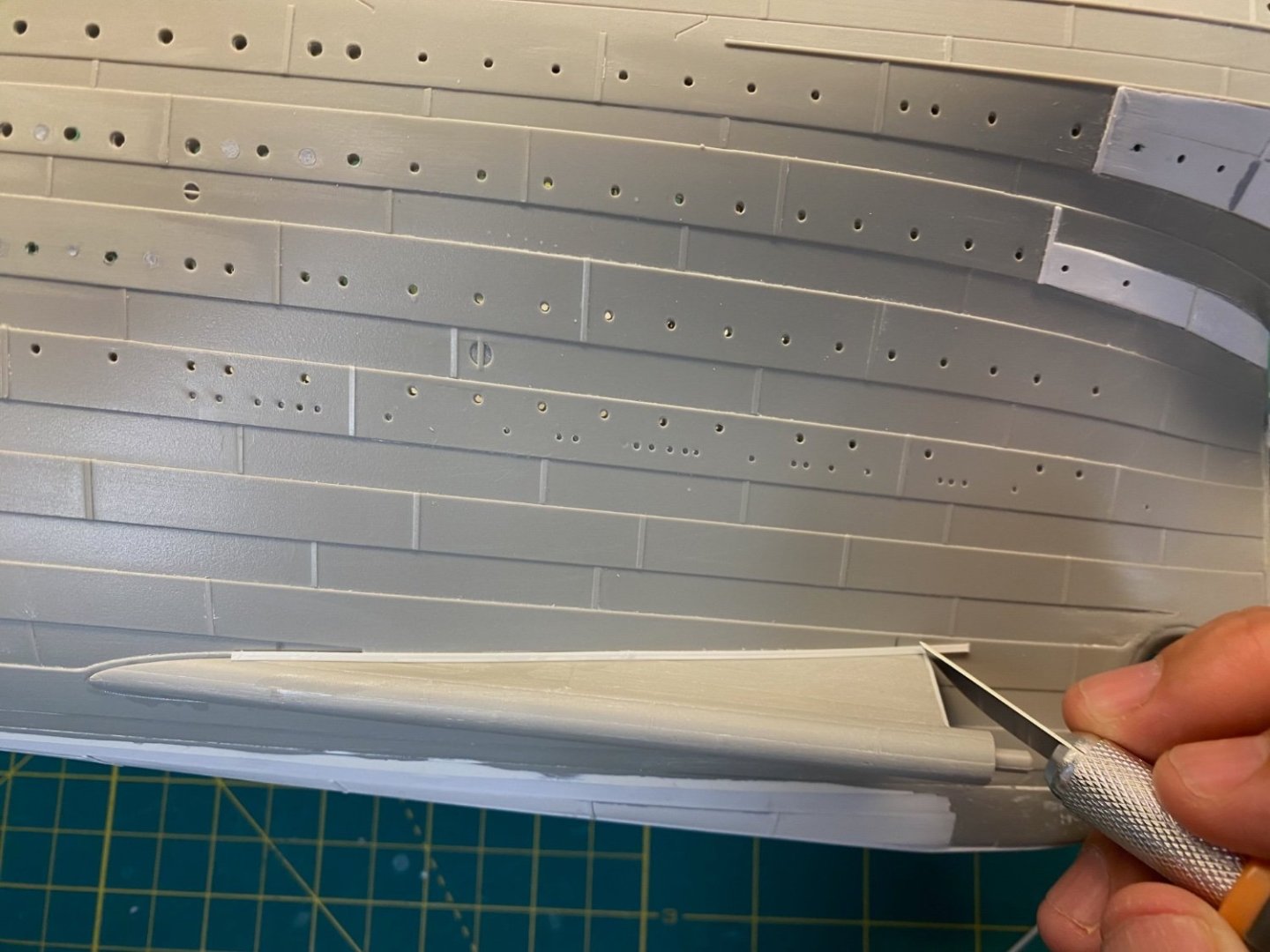
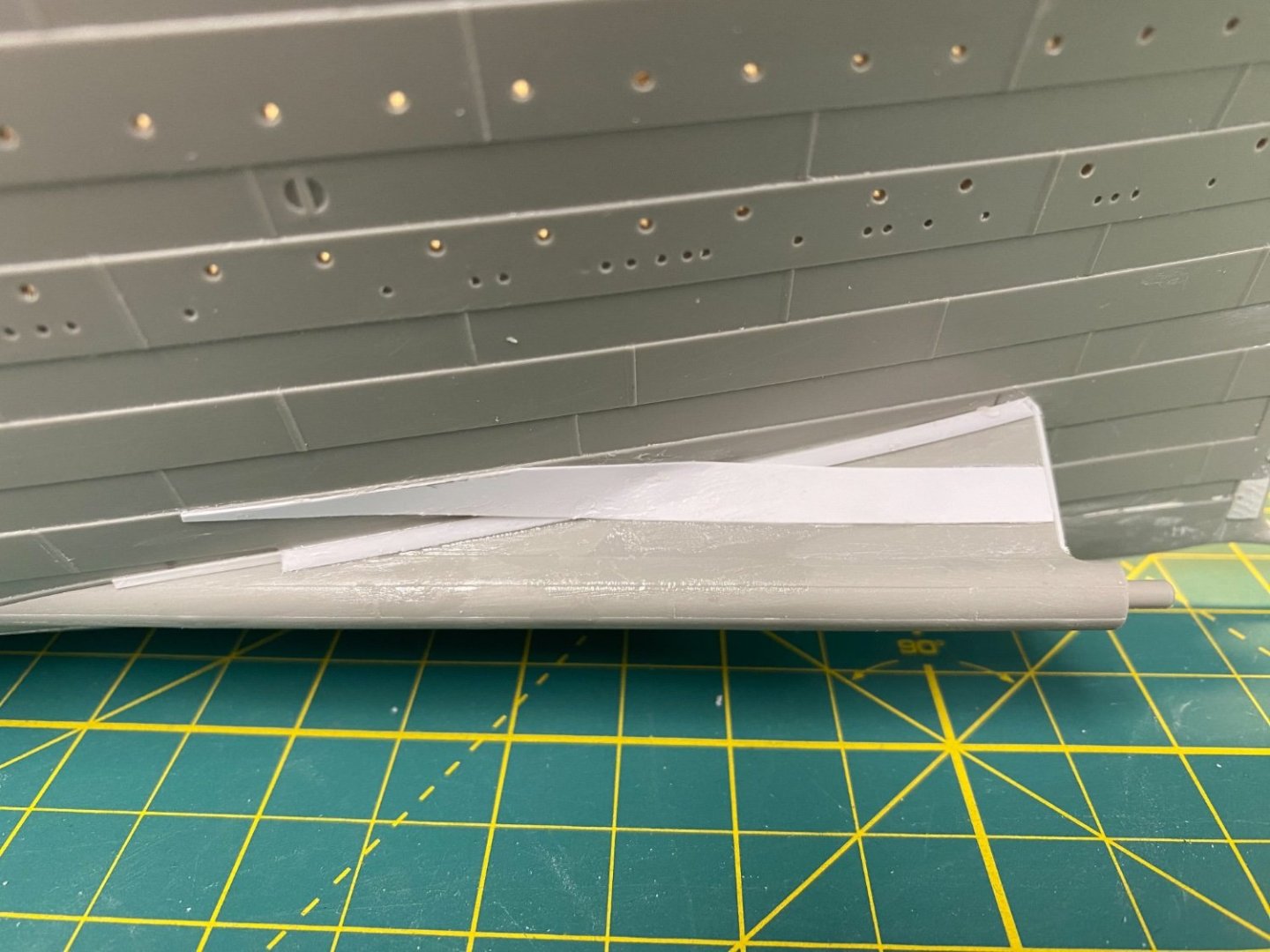
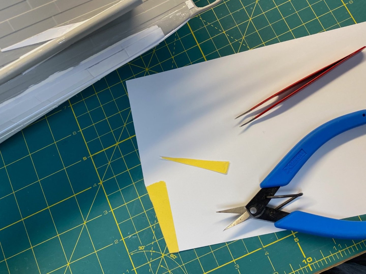
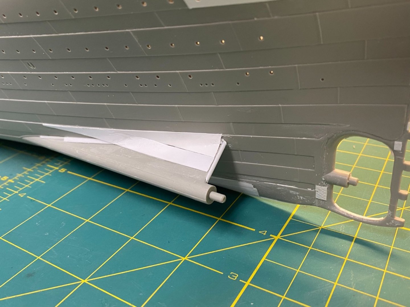
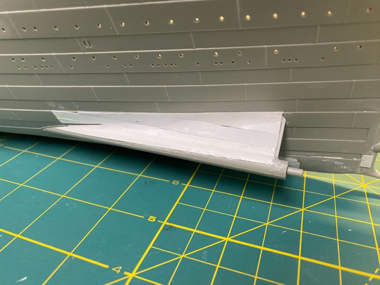
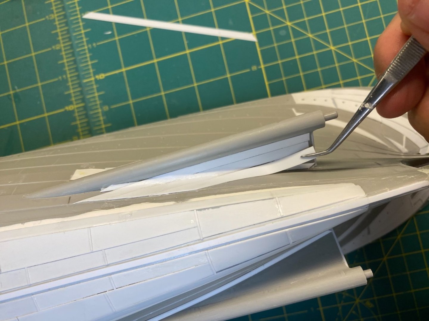
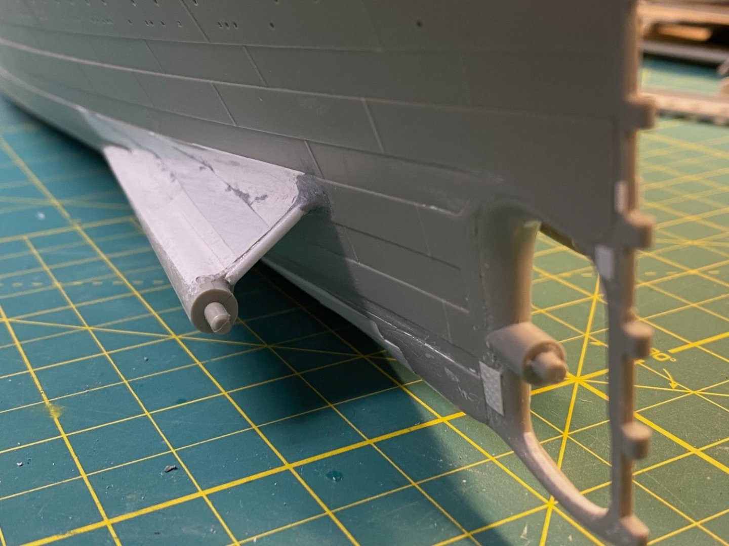
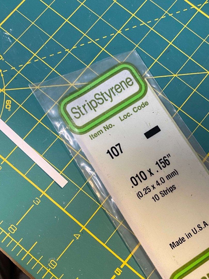
Propeller Wings The propeller wings on the Olympic class liners were graceful appendages that blended smoothly into the hull plating while supporting the massive prop shafts and propellers. The Trumpeter kit representations…not so graceful. This is one of those Trumpeter adaptations that don’t match well with the actual ship. The kit wings meet the kit hull abruptly and look a bit out of place. In fact, the Trumpeter kit has these placed a bit too low and they don’t align well to the nearby hull strakes – which are also out of alignment with what was in place on the Titanic. The detail on these pieces is subpar… The plating is wrong and a little overscale. There seem to be some 3D printed versions available online, but I think this is another case where these versions are too accurate – they’ll look out of place on the model. I’ll reach back into my bin of styrene sheets and strips and try to make the best of what the kit provides. I won’t try to correct the hull strakes and the prop wing placement, but I can add better detail and get things to blend more seamlessly. First, I’ll remove all the surface detail from the pieces: I cemented the pieces together and added half round strips to the ends: After attaching the wings to the kit, I was worried that there wasn’t enough surface contact where they meet the hull. I’ve reinforced them by adding thin half round strips into the crease where they meet the hull. The curved side faces into the kit to maximize the surface contact: Next, another larger half round strip was added above the first to fill in the gap and provide an angled surface for the styrene strips that will blend into the hull strakes. I laid the first strip on the upper surface to serve as the baseline for the other elements. This was a .010 x .156 strip that was liberally doused with cement and pressed flat. The top edge was trimmed to match the adjoining hull strake. The remaining elements were fashioned from .005” Styrene sheet that I ordered directly from Evergreen… Hard to find these thin sheets at local hobby stores or model train shops. The next “plate” was traced using Tamiya Tape to make a template for a tight fit: …then transferred to the .005 sheet. The remaining plates were added using the same process. For the underside, strips of .010 x .156 were used. The ends were all trimmed to align with the bottom edge of the nearest hull strake. Any gaps or blemishes were filled with Tamiya modeling putty and sanded smooth after drying overnight: Some sample views: Still a bit more work to do… Including the starboard side wing. I’ll define the individual plates and add final details on the next post. Cheers, Evan


- 145 replies
-
- 18
-
-
-
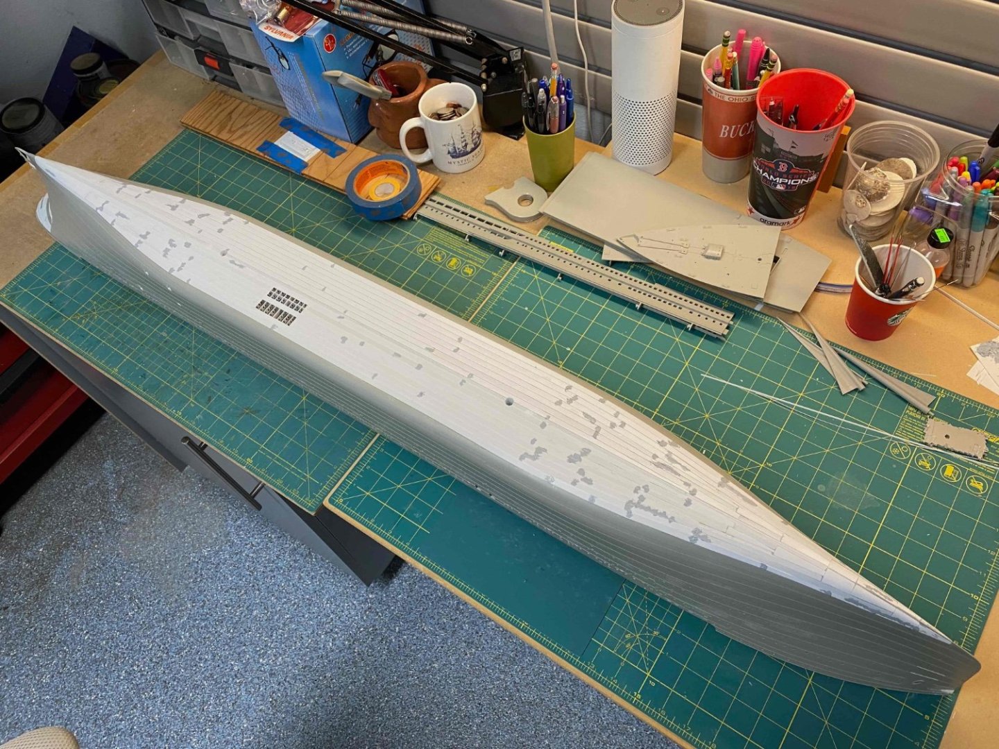
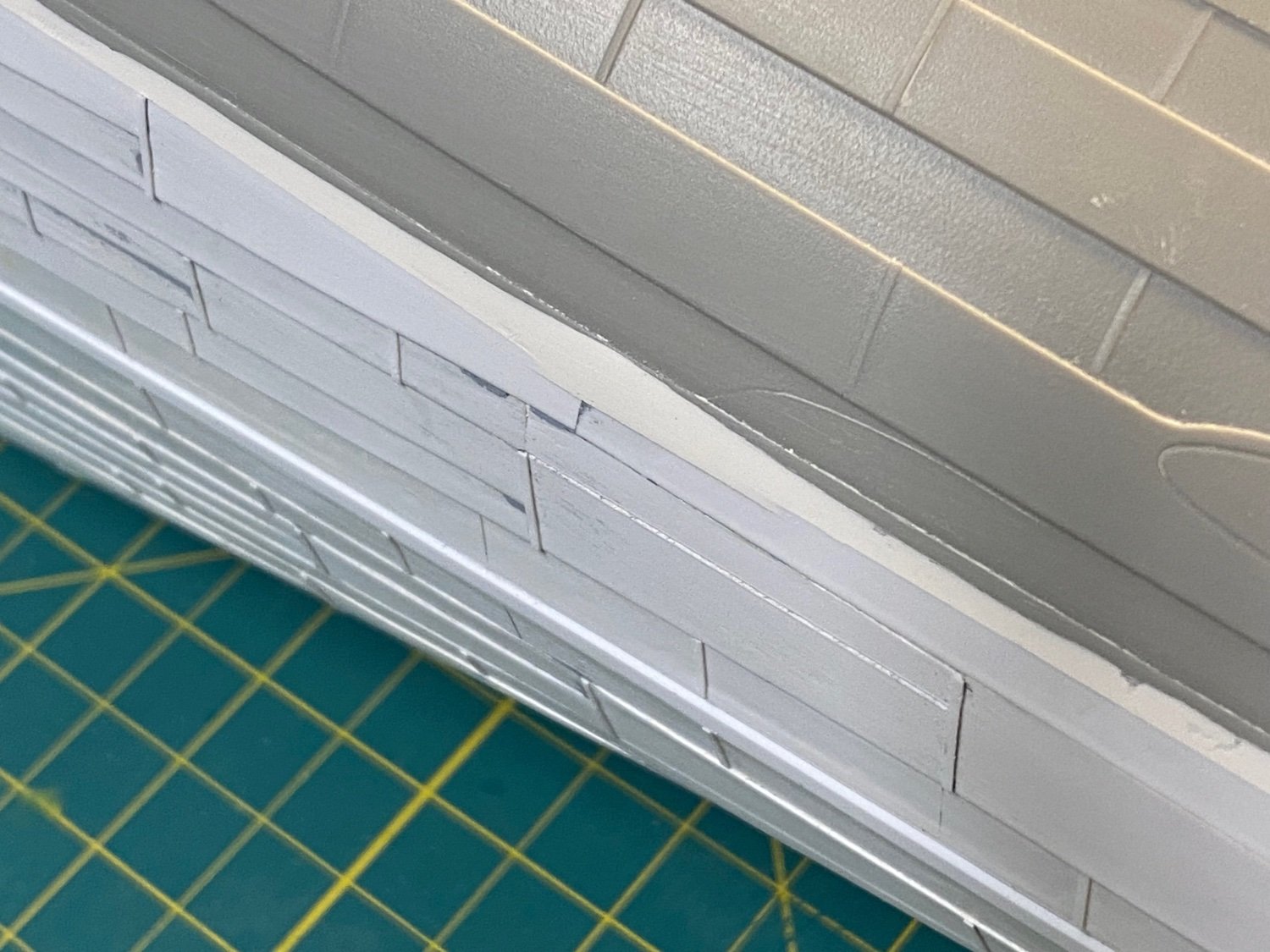
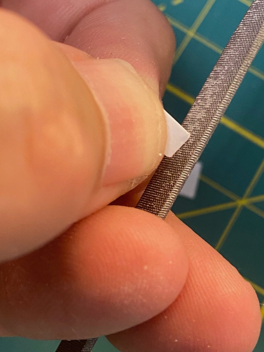
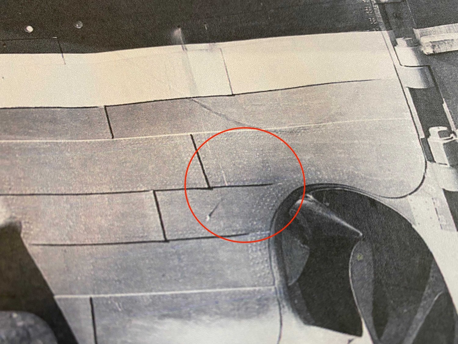
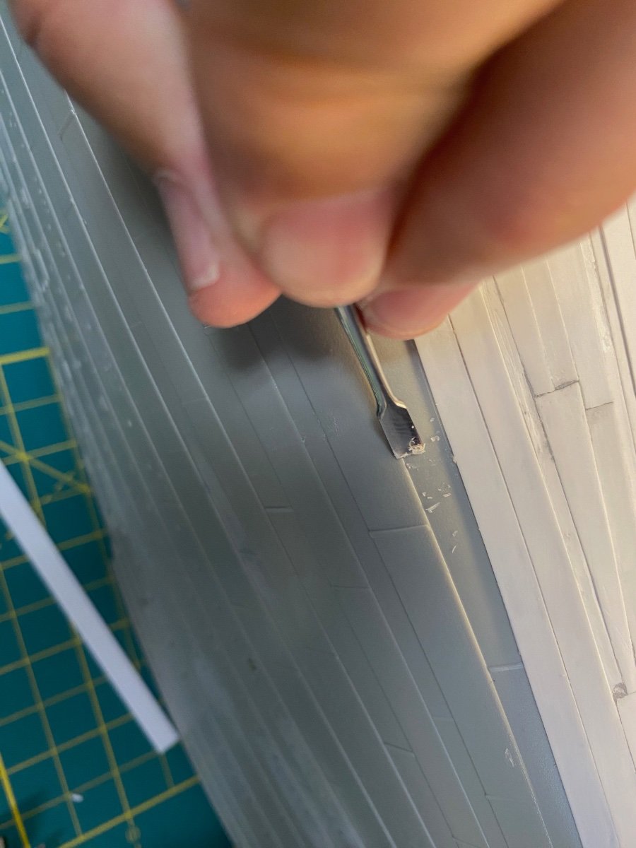
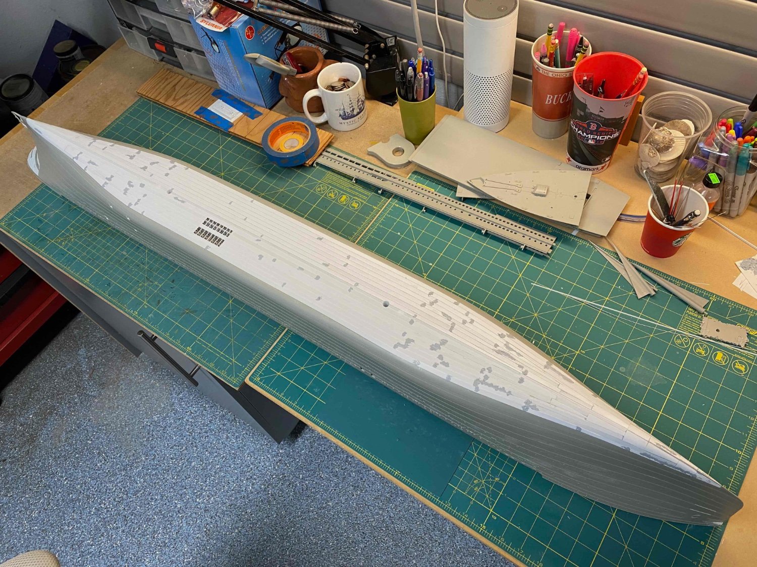
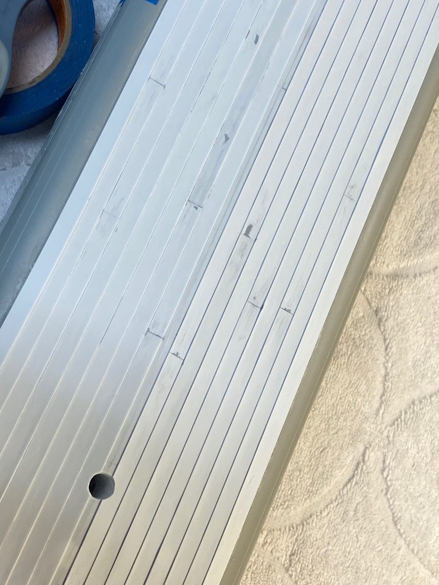
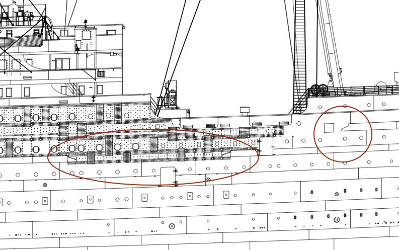
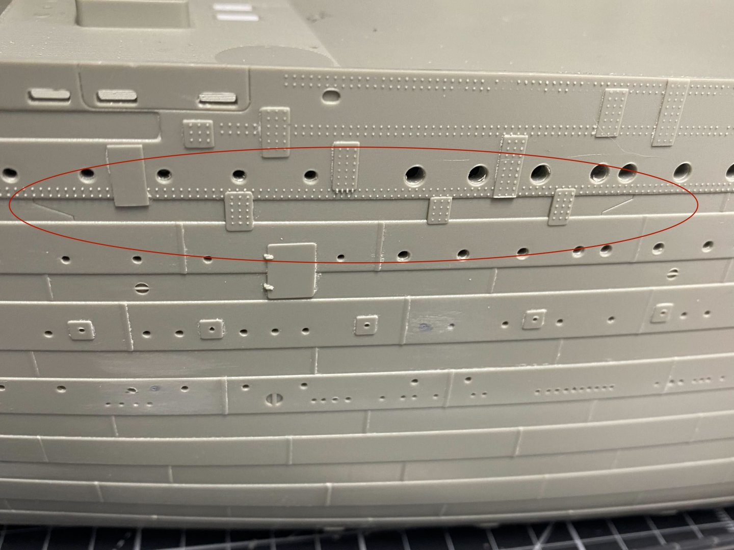
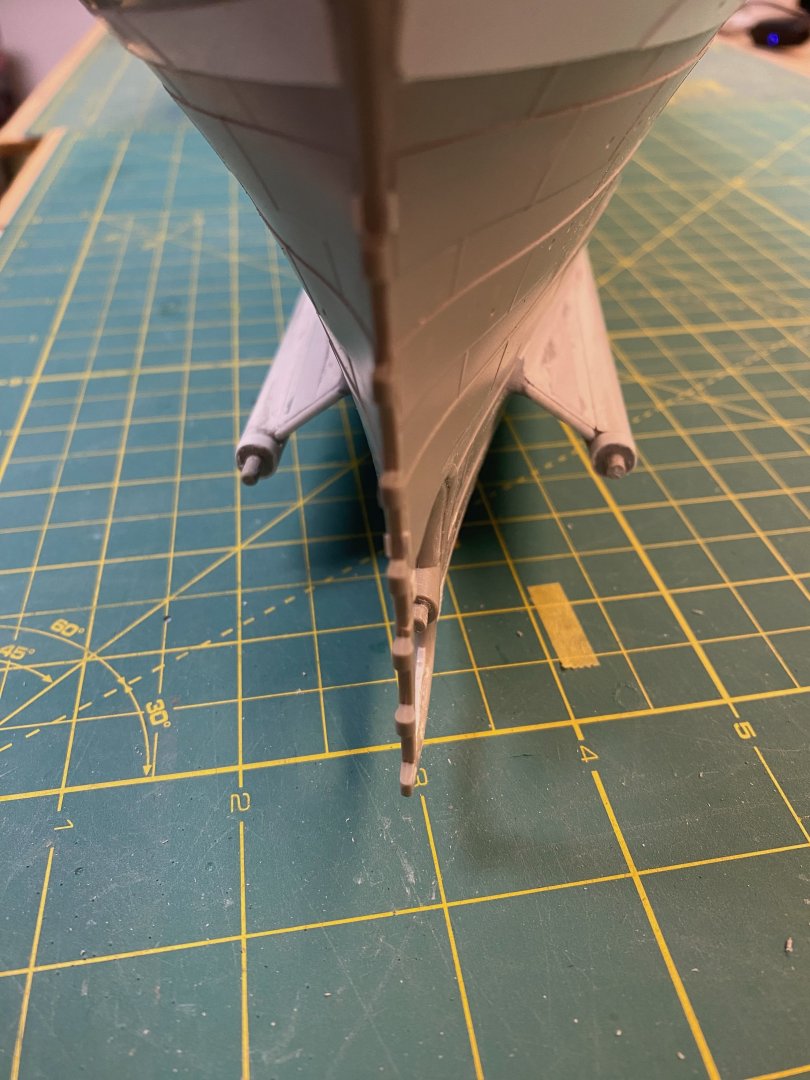
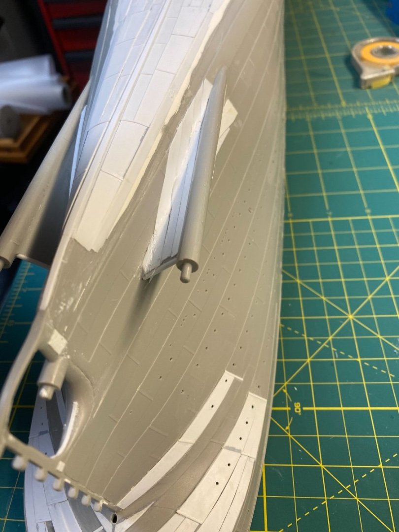
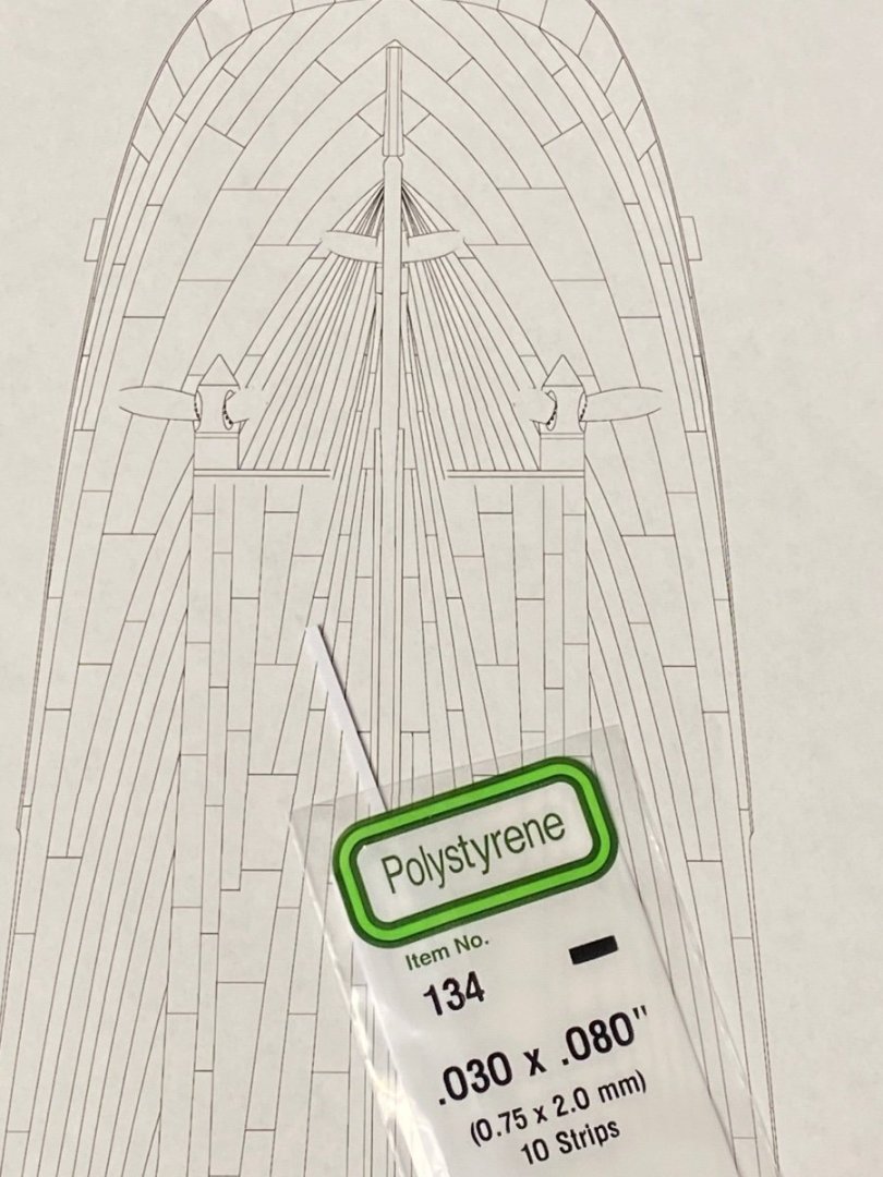
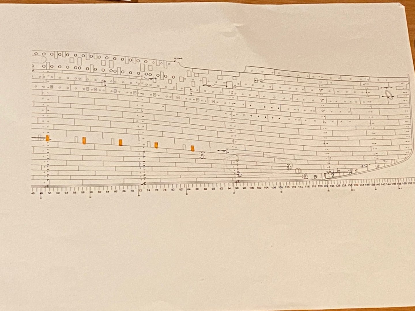
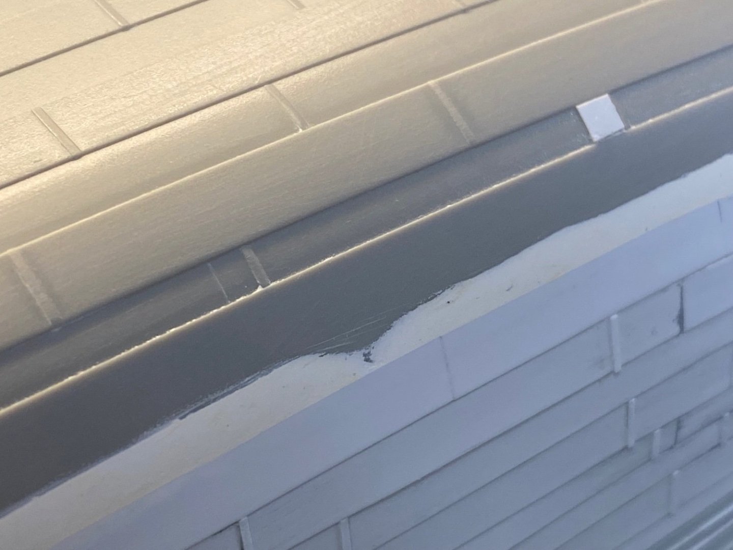
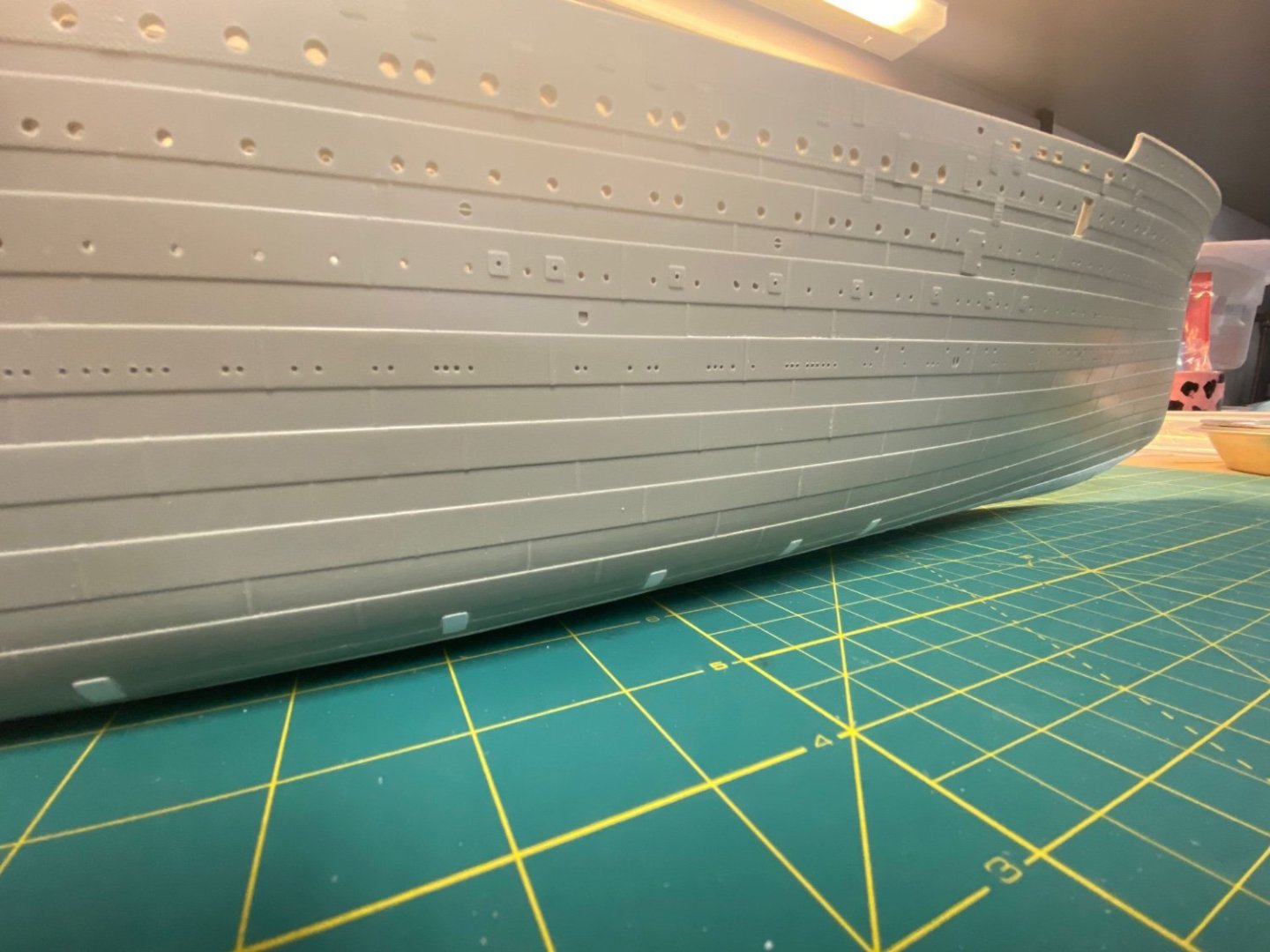
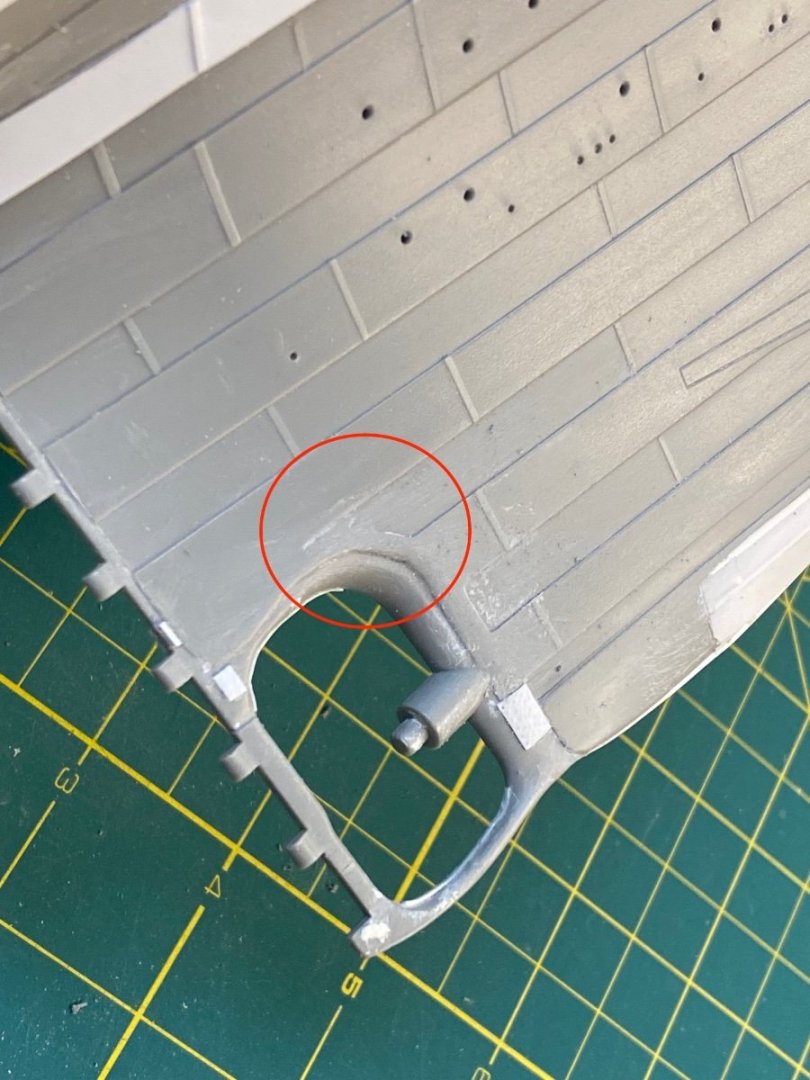
Center Keel Time to lay the keel down… Obviously this is where the actual ship began construction, but I’m only now getting to this critical element on my build. I laid the keel down in manageable sections using .030 x .080 Styrene strips. Not sure this would be exact to scale, but it closely lines up to the width shown on my 1/200 scale print of the hull bottom. The critical thing is to keep it straight all the way down the length of the underbody. I taped a straight edge against the styrene and began cementing down the aligned strip in two-inch increments – moving the straight edge along as I worked my way from bow to stern. I also had a small piece of scrap styrene that perfectly fit into the needed gap between the keel and the inner edge of the hull plating that I test fitted as I glued each strip. The forward most keel section was tapered to meet the kit keel at the bow. The stern section was angled down toward the sternpost and filed to blend. It really takes some effort to make sure that the keel stays straight and true all the way across the length of the hull. Butt Straps Generally, the hull plates were overlapped and riveted together across the length of the hull. There was, however, a section of strakes lower down in the hull that had the butt ends set flush together without the overlap. These plates were held together with “butt straps” – small plates riveted to the ends of the abutting hull plates. See my orange highlights in Bob Read’s hull plan: (Note that the port side butt straps are indicated with dotted outlines in Bob’s drawing and are offset port vs starboard.) The Trumpeter kit seems to include faint outlines of these straps in the approximately correct location forward of the bilge keels. No indication, however, on the strakes aft of the bilge keels. Bob’s drawing shows five of these forward and four aft. In a perfect world these butt straps would all line up against a single strake across the length of the kit underbody. This would include the tops of the butt straps that peek out above (and below) the bilge keels. Unfortunately, the compromises made by Trumpeter in molding the hull have made it tough to add these butt straps with all the top edges aligned against one hull strake. I’ll need to fudge things a bit to get these represented on my model. I’ll go ahead and use the kit outlined versions forward of the bilge keels for positioning my straps. Aft of the keel I’ll align them against the existing kit hull strakes - marked first with a pencil. Thin .010 x .156 strips of styrene will be used for these butt straps: These will all sit in line with the “in” strakes of the molded hull. I inserted small snips of styrene to fill the gap to create a flush surface before overlaying the butt straps: The corners of the styrene were first rounded and then cemented in place. Once put in place, I came back along and sanded down the straps to reduce the dimension – didn’t want these to stand out too proud against the hull. Tape protected the hull while I used an Emory board. Sample views: I’ve decided to hold off on adding the bilge keels for now. There is much abuse left to deliver on the hull and I think these keels will be fragile and vulnerable as I flip the hull on its side and upside down to make more modifications. I can be patient and add these (along with more butt straps) at a later stage. Miscellaneous Detail I’ve also been tending to some of the smaller details along the hull. The historic photos show a small crease near the hull stern plates: I grabbed the hobby knife and a micro chisel and went to work. Thanks again for the interest everyone has shown (and the patience between updates). Pondering next steps – probably the propeller wings. Cheers, Evan


- 145 replies
-
- 13
-
-
-
I suppose the true purpose of this tackle will remain a head scratcher... I really do think it is bowsing tackle for securing the cutters to the A-deck... Bob's theory about recovering the tangled boat falls is sketchy in my mind. I really don't see a problem there that needs his complex solution. Onward! Evan
-
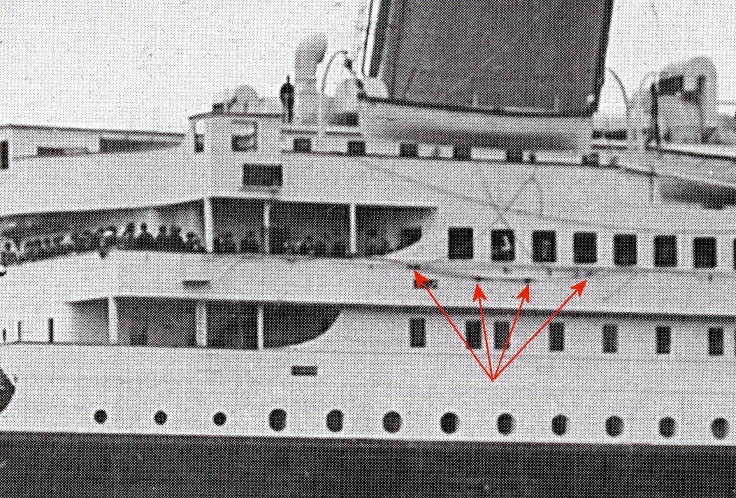
Here is Bob Read's explanation for this rig: Titanic Cutter block and tackle explanation His theory strikes me as overkill for the stated problem. I would guess that the Olympic class has a problem unique to the cutters that would call for a common and simple remedy using this tackle. Unlike the other lifeboats, the cutters have another boat stored directly underneath them and between the davits at the boat deck level. This makes loading the cutters from the boat deck awkward, cumbersome, and potentially dangerous. I suggest that it was oftentimes preferred to lower the cutters one level and have the boat crew hop aboard through an open window. What we are seeing are the Bowsing Tackles used to secure the boat to the side of the ship while loading or unloading in times of active seas or deep ocean swells. This rigging was common in 1912 and still in use today. Perhaps a Bosun mate clambers into the cutter from the boat deck, releases the gripes, unlocks the falls, and rides the boat down to the A-deck. He indicates by voice and hand signal to the davit operator to stop, reaches across with a boat hook and pulls the Bowsing Tackle inboard and secures it bow and stern. Fenders tied to the thwarts are already dangling over the side to cushion the gunwales. The tackle is pulled taut to secure the cutter to the ships side to prevent any swinging or oscillation while the oarsmen and cox’n hop on board through an open A-Deck window. The Bowsing Tackle is eased out to align the boat back under the davits, the tackle is cast off, then a signal is given to the davit operator, and the lowering proceeds to the water. I think that the explanation is straightforward… These are the Bowsing tackles pre-rigged for securing the cutters to the A-deck siding while loading (and unloading) as circumstances merit. So far, NOBODY has bought into my theory. I've got no evidence to support my thinking, and Bob Read has way more credibility in this space to get folks aligned to his ideas. Cheers Evan
-
@Roger PellettInteresting... How would that work? And if so, do we see this rig on other ships? Perhaps the pilot would board thru one of the lower level access doors on the ship's side? Cheers Evan
-
Folks - Apologies for the lack of progress on my log. A bit of travel and a bunch of honey-dos related to home projects and settling my kids back into college have kept me away. I'm back at the workbench this week and should have some small gains to share soon regarding the center keel and some of the underbody butt straps. In the meantime there has been some lively discussion on some of the Titanic FB forums regarding the purpose of the "mystery" tackle below the emergency cutters that shows in many photos: The groups are wrestling with a coherent explanation for the purpose of this rigging. Bob Read has offered an elaborate explanation involving the recovery of the twisted and tangled boat falls, but I'm skeptical. To give some quick context - this setup only shows up when Titanic (and Olympic) are putting to sea and the emergency cutters are swayed outboard in the ready position. When in port the cutters are stored inboard and this rigging is stowed. I have my own thoughts, but will hold back to not bias any opinions... Any ideas from the wider viewership?? Cheers Evan

-
@Snug Harbor Johnny Aye - one of many overlapping circumstances that collectively led to the tragedy. If we could only hop into a Time Machine and go back and tweak one or two small things...! Cheers Evan
-
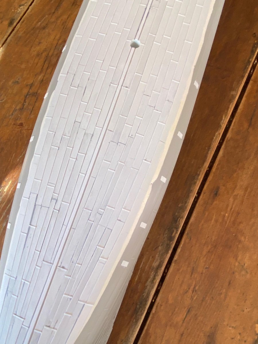
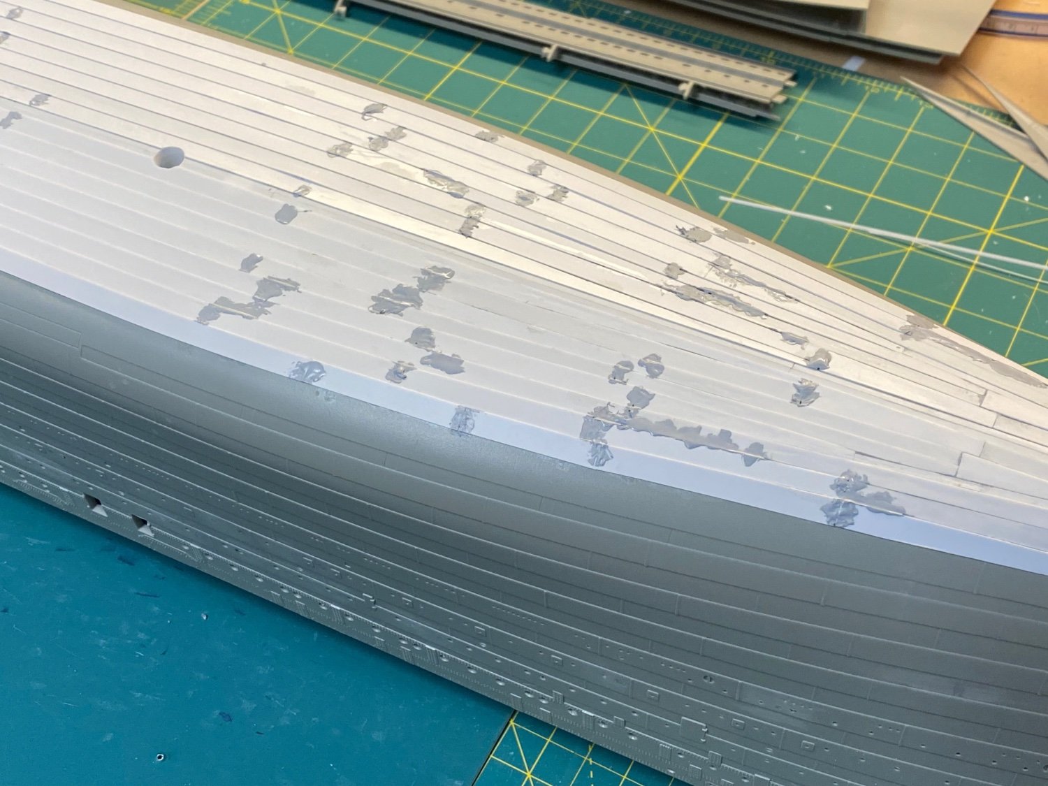
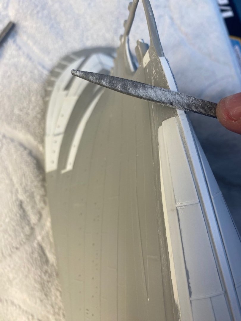
Bottom Plates Up next, I needed to blend the outer edges of the new bottom plating with the kit hull… I didn’t like having that .010 lip all around the bottom of the hull. Out came the Miliput again… After taping around a narrow band that encompassed the outer edge and enough area for a smooth transition into the kit, I mixed up a small batch of the Miliput and spread a thin coat the length of the edge – port and starboard. I was careful to keep it wet and kept smoothing it down and scraping with a scrap of styrene until it was reasonably thin and just covering the styrene edge. I then removed the tape and let it all dry overnight. Came back the next day and sanded the Miliput down using various grit sandpaper – coarse, medium, fine until it was blended into the kit surface and smooth to the touch. A lot more effort than I thought it’d be before I started! Another part of the kit that will be refined after a layer of primer. In the meantime, I cut a length of .250 wide styrene to match the general length between butt joins on the upper hull to use as a marking template. I then marked off the individual plates in pencil across the hull bottom mid-section. Adjustments were made at the bow and stern to accommodate the more complex shapes. Next, I snipped many dozens of .250 width strips of .010 x.030 styrene to approximate the kit butt joins. I used some scrap styrene as a template: These were cemented to the hull in the marked positions… It took about four days’ worth of my modeling time, but the plates are complete (except for a few on the outer edges that will wait until final tuning). Here is a view of my bottom plate butt joins along with the kit side versions: Not too far off. Some sample views: Butt Straps and bottom keel up next. Cheers, Evan


-
@Roger Pellett Perhaps it'll give me an opportunity to describe it as the little known glass bottom observation area available only to first class passengers...??!!!
-
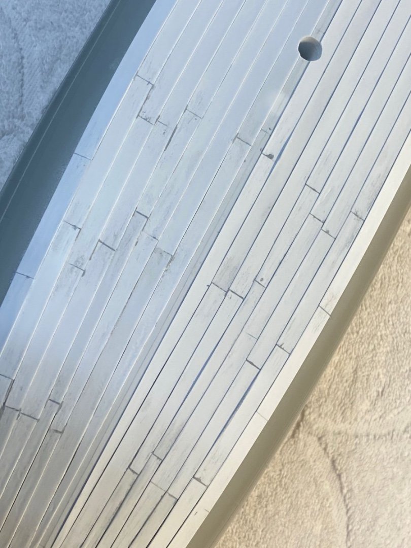
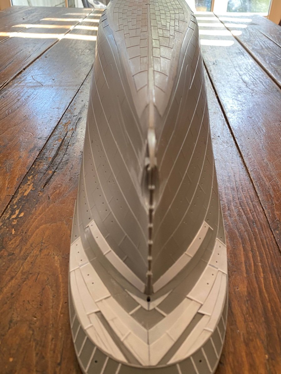
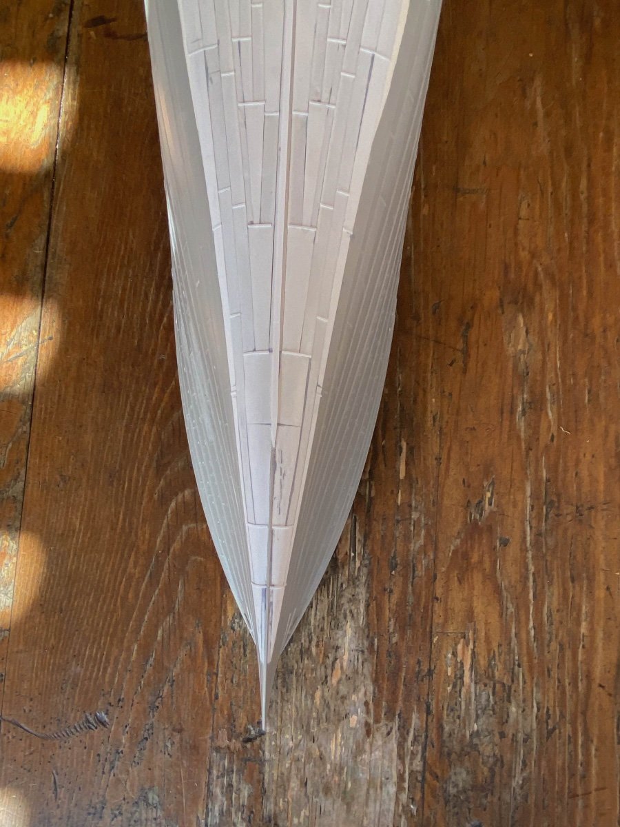
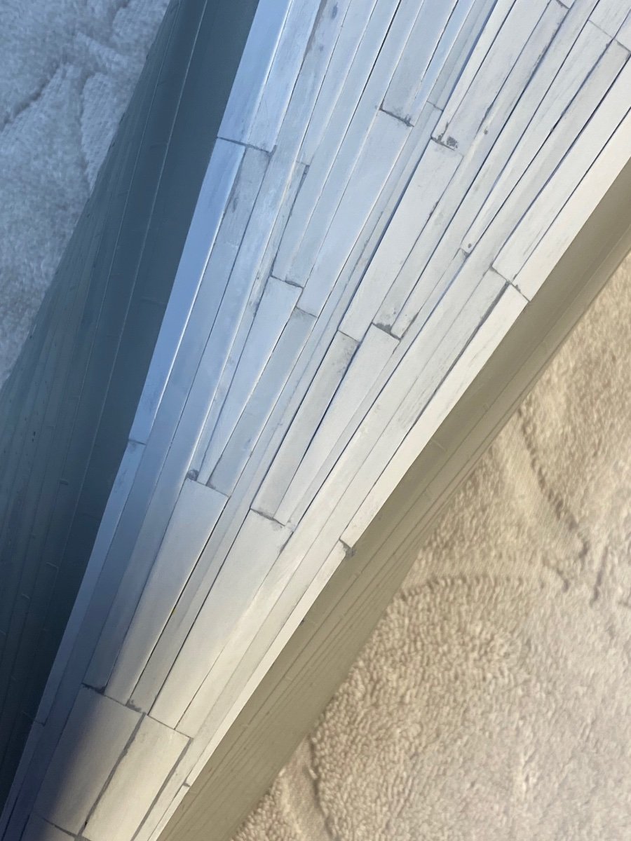
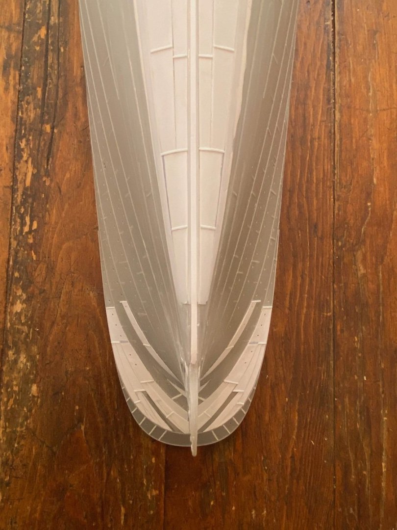
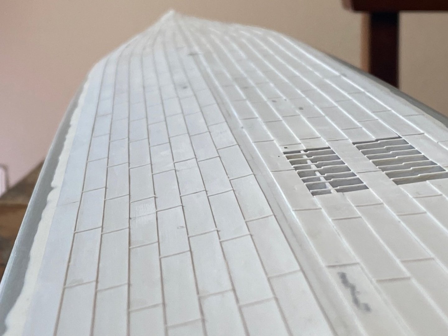
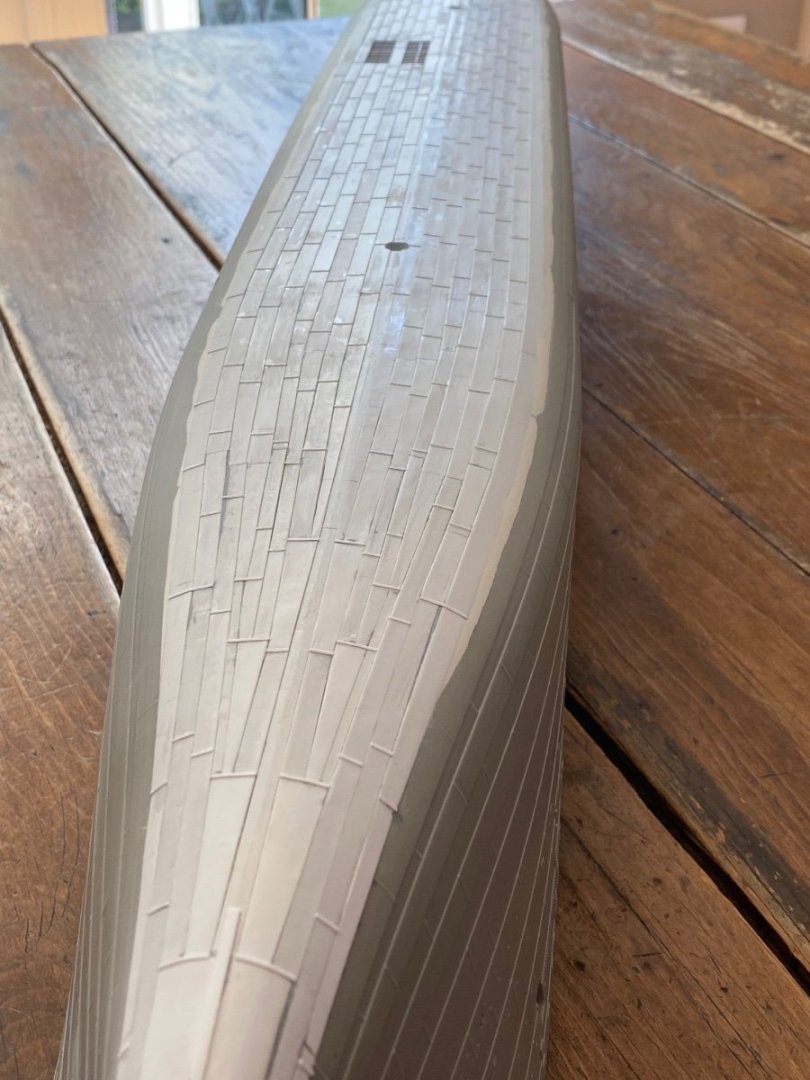
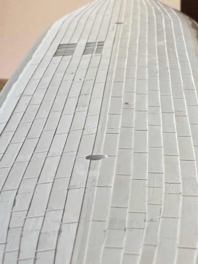
Thanks again to all who are following along... I appreciate the continued interest. Clinker Strakes I’ve already confessed to cheating on the Clinker plating… I didn’t overlap the plates on the hull bottom. Instead, I simulated the overlap by affixing a strip of .010 x .030 styrene to the underside of the adjoining edge of each .010 x.250 strake before cementing each tightly against the preceding row. This lifted the adjoining edge and provided a more consistent clinker effect across the entire underside of the ship. Very simple to do… I laid the .030 strip against a small metal ruler abutting each of the styrene strakes and laid down a bead of thin Tamiya cement along the length being careful to keep the strip tight against the ruler as I went along. The capillary action filled in along the seam and affixed the strip nicely. Then these were flipped over and cemented to the hull using Plastruct Cement as I pushed the styrene firmly against the preceding row. I could cover a lot of territory across the mid-section with a few full-length strips. Same process for the shorter strips at the bow and stern. In a few cases, I only added the .010 x.030 strip to half of the strake to help transition the plate to the ends of the ship. I filled in the recessed plate on the Trumpeter kit bow so that the bottom plating was consistent. I first scraped away the molded butt joins to get a flat surface. Once all the hull strakes were laid down, I came back along with Tamiya Putty (and occasional Sprue Goo) to fill in the seams to give a smooth and consistent surface. Here are close ups of the Bow… Transition section… Midships. And finally, a few closer views of the clinker effect: A bit more work needed to smooth out the outer edges to blend with the kit before I start adding the butt joins to establish the pattern of individual plates across the bottom. Cheers, Evan