


FSwart
-
Posts
10 -
Joined
-
Last visited
Content Type
Profiles
Forums
Gallery
Events
Posts posted by FSwart
-
-
Small Update:
Having recently acquired a CNC Mill/Router I decided to machine most parts for my Triton build. The CNC software is quite powerful, and has the ability to import toolpaths from images directly; however it does generate a few errors from the images. Maybe I’m just a perfectionist, but I decided not to use the image import function and instead redraw the plans…
I sent a PM to Chuck, just to check if redrawing the plans doesn’t violate the copyright terms, and luckily it does not.
So it was back to the drawing board (CAD workspace???)…
I use AutoCAD2012, and I know just enough to be dangerous. Fortunately I found a feature which is quite useful, more on this in just a moment.
I am not going to go into much detail about redrawing/tracing plans; Wayne has written a superb tutorial regarding this. I started using this method, first converting the PDF drawings to Jpeg images, importing into CAD and then tracing the lines, a very tedious and labour intensive process…
Now to the new (Better?- I don’t know, but it works quite well for me) method:
By chance I stumbled upon a feature in AutoCAD (Not sure if Turbo Cad etc. supports this) called PDF Underlay, which as the name suggests puts a PDF underlay into the workspace. I figured it was a bonus, now I don’t have to convert the drawings to Jpeg files first. Upon further examination however I discovered that the lines in the PDF underlay had object snaps, so now I can start a pollyline or spline at one of these snaps, and simply follow the snaps on the line I wish to trace.
I’m not going to post the entire procedure for every part being redrawn here, just show the basic steps involved. I am only posting this as I think someone might find it usefull.
First up is structuring the drawings (method borrowed from Matrim, Amphion Drafts MK3).
Second will be tracing the imported PDF file. Copy will be saved as a *.DWG file extension.
Third will be converting the file to a *.DXF for the CNC software. While the software can automatically compensate for cutter radius, it is a potential pitfall. The part to be cut will be treated as follows:
- Join all lines/splines/pollylines/arcs to form one continuous pollyline or spline.
- Offset the continuous pollyline or spline with the cutter radius towards the waste side of the wood to get the new center toolpath line.
- Checking for any gaps or crossed lines in the line.
- Scale the parts from 1:1 to 1:24.
Fourth will be importing the *.DXF into the CNC software to generate the necessary G Code.
This is the process explained with a few pictures:
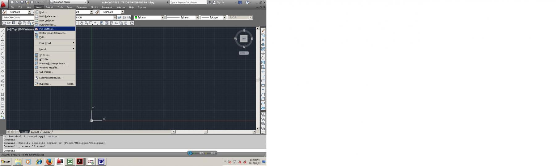
1: Inserting PDF Underlay.

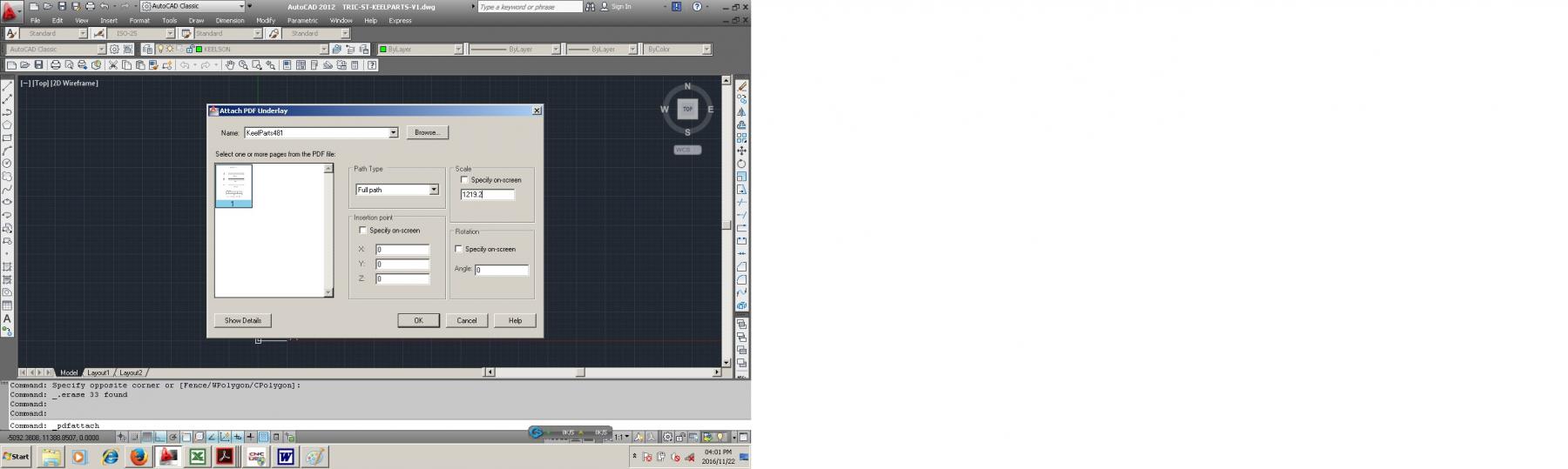
2: Scale PDF Underlay (Scale factor 1219.2 was determined by multiplying 25.4 (1 inch in mm) by 48 (Scale of drawing)).

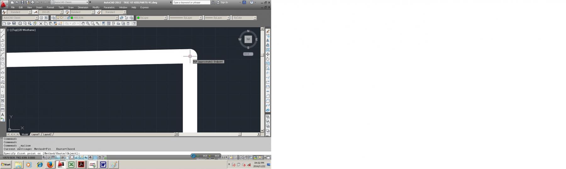
3: Start tracing at object snap.
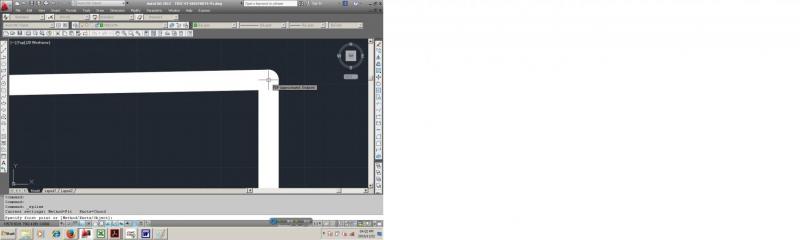
4: Continue tracing following object snaps along line.
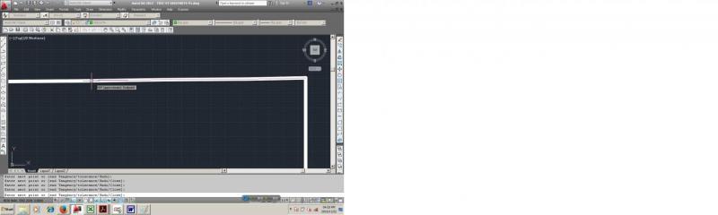
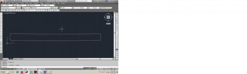
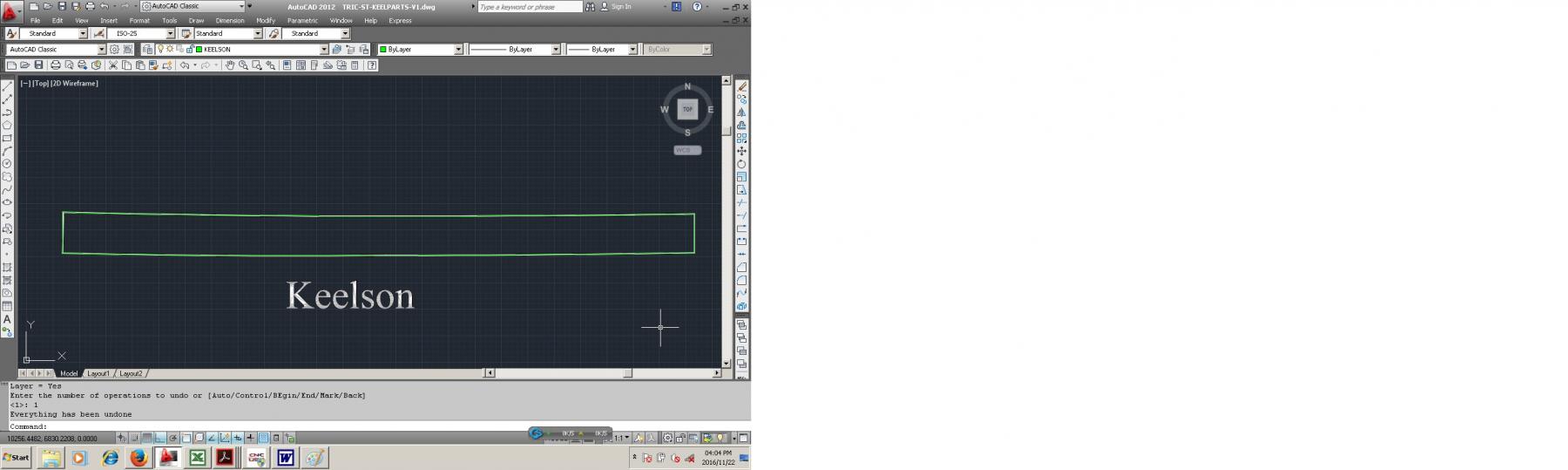
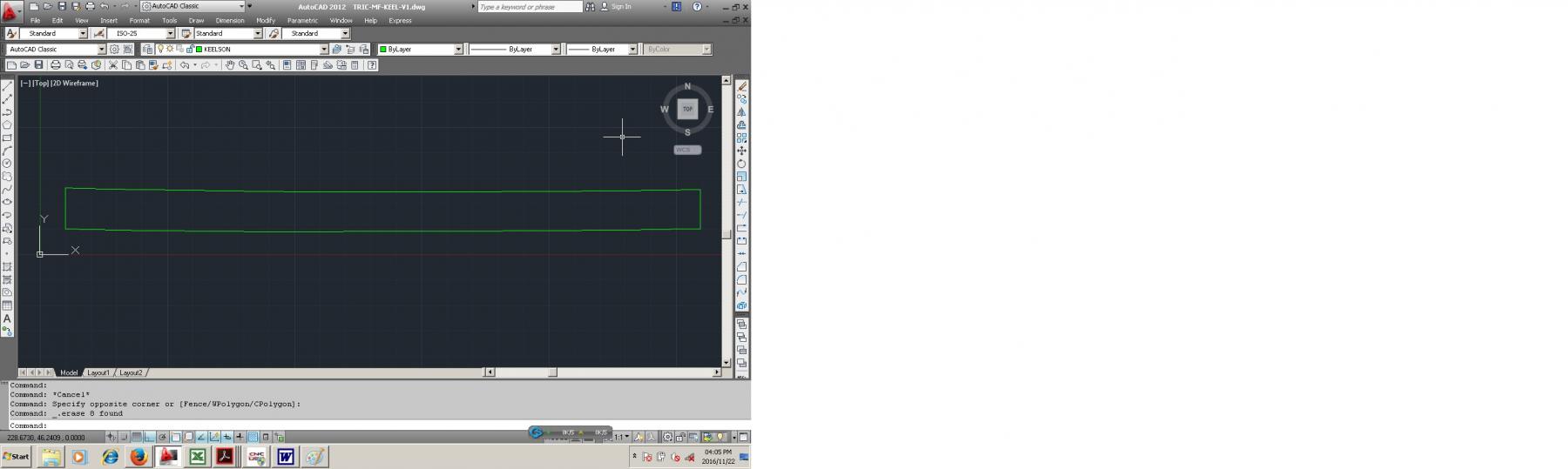
5: Result of tracing.

6: Join lines and splines.

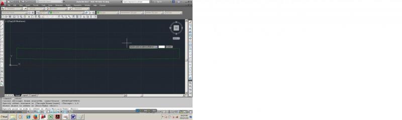
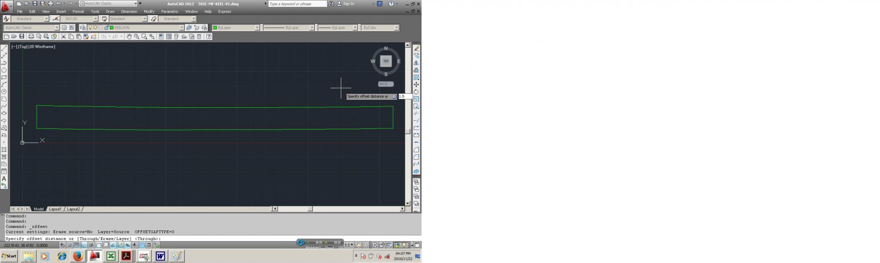
7: Offset procedure 1:
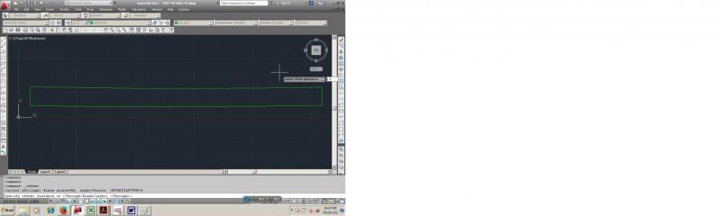
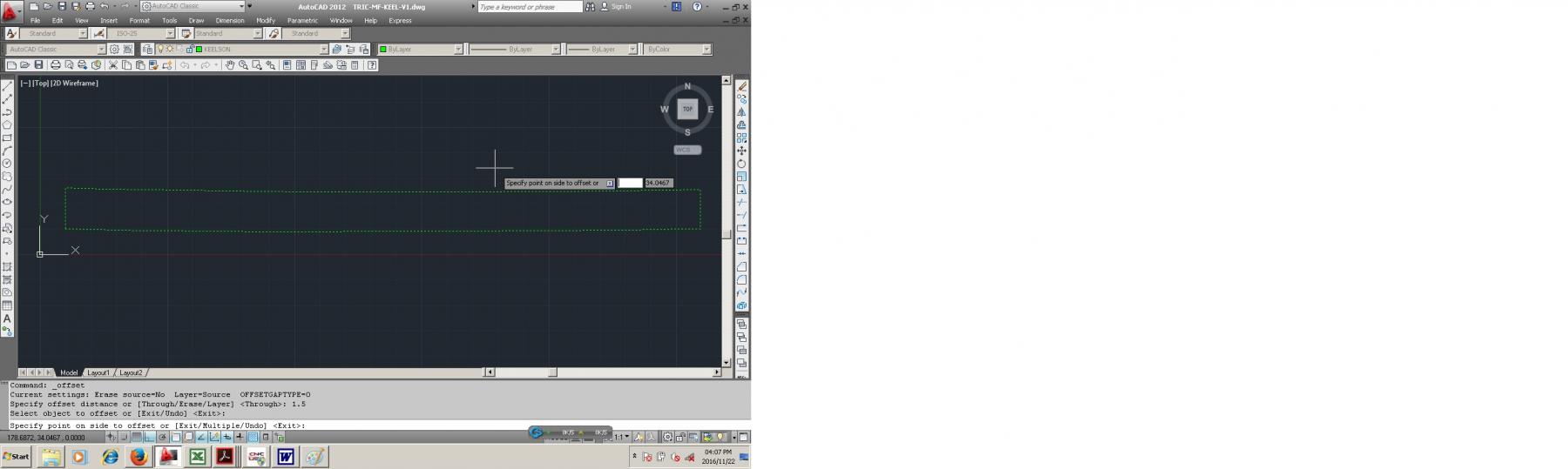
8: Offset procedure 2:
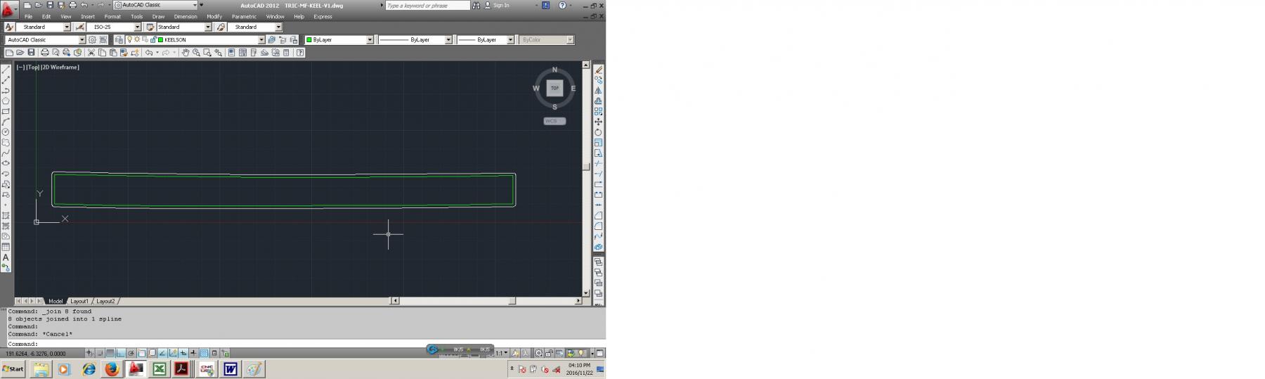
9: Offset result:

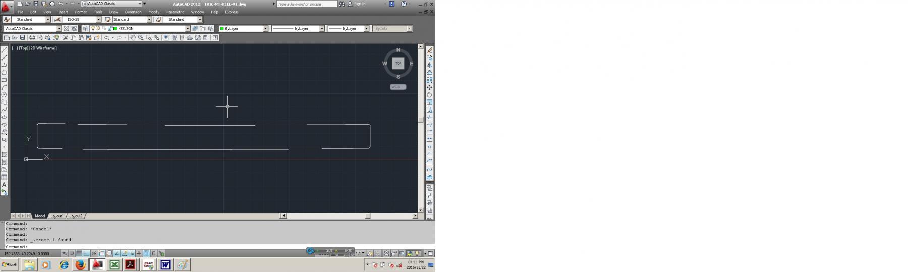
10: Change layer of new line from keelson to toolpath.

11: Delete original trace line and save as DXF.
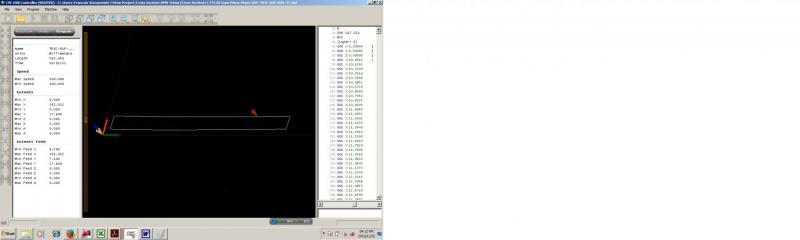
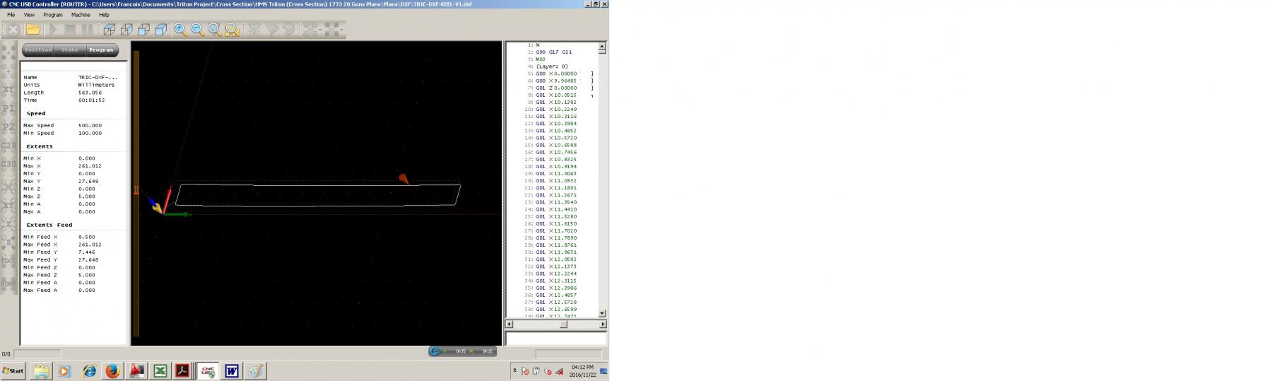
12: Import DXF into CNC software and generate G Code, note that the software calculates the length of the cut, which in this case is 563.056mm and also calculates the time for the cut, which will be the length divided by the feedrate and multiplied by a compensation factor (compensation for acceleration and deceleration which occurs at changes of direction)
-
Hi Mark,
I am no expert with CAD, I know just enough to be dangerous...
However the red rectangle you are referring to is the color of the layer you used when inserting the image. It may be possible to make that particular layer transparent. Someone who knows CAD better might be able to help with this. I think you said that you are using AutoCAD 2016LT, I use AutoCAD2012 so I am not sure if That feature is available.
Always ask google first!
Have not tested this, but it should work...
-
Greetings everyone;
Following on from all the help which I received from fatfingers (for which thank you again) I have found out one thing which may interest fellow-modellers/draughtsmen, and have a further request for any advice or help.
I am now able to insert a raster image in a drawing, on top of my background layer. This still has the white rectangle, but, if the image has been made transparent by the process outlined above by fatfingers, it is then possible, using AutoCAD's own properties menu, to turn on and off the background transparency of the inserted image. The white background disappears, leaving the image clear.
However, I am still left with the rectangular outline around the inserted object, and I wonder if any other members have an idea of how to remove this unwelcome survivor.
All the best,
Mark P
Hi Mark,
I am no expert with CAD, I know just enough to be dangerous...
However the red rectangle you are referring to is the color of the layer you used when inserting the image. It may be possible to make that particular layer transparent. Someone who knows CAD better might be able to help with this. I think you said that you are using AutoCAD 2016LT, I use AutoCAD2012 so I am not sure if That feature is available.
-
Thanks all.
Where is the cross section located on the full model? Obviously the boarding steps define the location. Does anyone have a sheer plan photo to help me locate it? The reason I ask is that there were several scarf joints in the keel and I want to see if including one is appropriate in the cross section. if I know where the section is on the sheer plan view, I can locate the scarf joints on the keel .pdf for the full Triton model. Thanks.
My preliminary wood selections are boxwood for the keel, swiss pear for the keelson, rosewood for the false keel and cherry for the hull framing.
Dave
Dave, as far as I am aware the cross section plans are a simplified version of the full build with some minor differences (I did check for curiosity sake and it is so, and there are scarph joints in that section). It might be a good idea to use the full builds keel drawing to obtain the detail that you are looking for.
-
I am currently building the Triton in 1:24 scale. (Project is currently suspended as with my other builds due to space constraints)
I just asked the print shop to print at 200%, as far as copyright goes where I live people don't care so that wasn't an issue. I also do all my builds using the metric system, so I convert everything to millimeters, just my personal preference and I grew up with the metric system. I use an app and a set of conversion tables to do the conversions, just more practical than a pen and paper or a calculator. Just my 2 (zimbabwe)cents

-
Probably also abit belated and slightly offtopic, but I have found that when attaching PE wall panels it helps to roughen up the surface. For this sandpaper will suffice, however I personally sandblast the piece.
Regarding glue I've found that security cable glue works excellent.
- mtaylor and thibaultron
-
 2
2
-
-
Good day all.
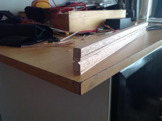
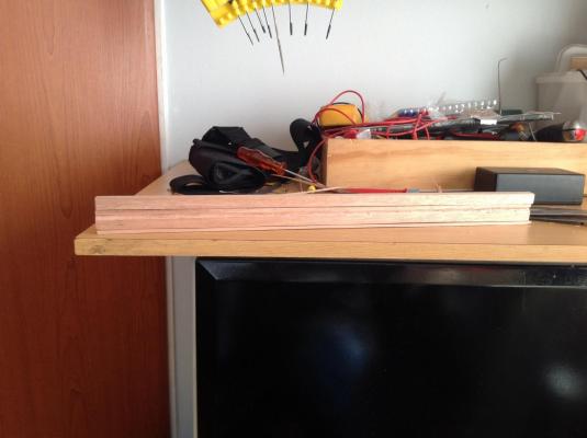
Started my build of the Triton crossection today in 1:24 scale.
This is my first attemp at scratchbuilding and also my first model from the age of sail.
May I request the moderators to grant me access to the rest of the drawings?
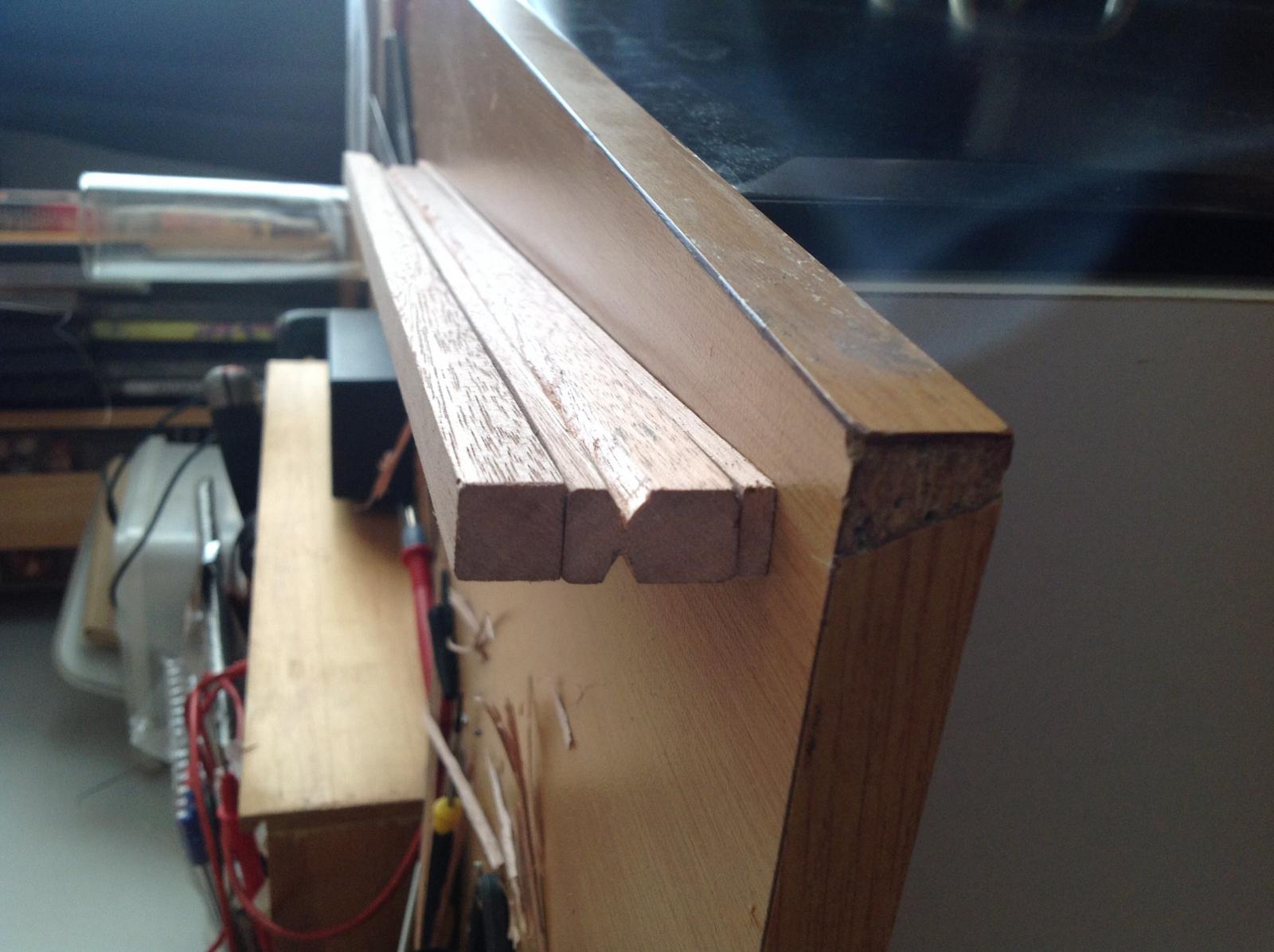
Attached are a few pictures of as things stand at the moment, with the keelson, keel and false keel cut and lightly sanded.


CA Glue & Silicone Mat
in Modeling tools and Workshop Equipment
Posted
I have not experienced this myself, however I can only comment on my experience with the materials used.
Self healing cutting mats are usually made of polyurethane rubber, which in its uncured state sticks to virtually anything that doesn't have a release agent on it. Silicone rubber on the other hand doesn't stick to anything but itself. I have not seen any cutting mats made out of silicone rubber, and as far as I know they don't have self healing properties.
So if you have a self healing cutting mat, chances are that it is made out of a polyurethane compound and CA glue will stick to it.
Hope this helps.