norm1116
-
Posts
59 -
Joined
-
Last visited
Content Type
Profiles
Forums
Gallery
Events
Everything posted by norm1116
-
 Hello all! After a lot of time, I have decided to abandon the Portland project. I lost all motivation and desire to complete it. I gave away the Portland to someone who may complete the ship. They have visited this log before and are familiar with the status of the boat. It's been great! Thanks for all of the support and I apologize for not seeing this through.
 -
I found a couple of really interesting YouTube videos of walking beam engines. These two you have to see! Video 1 Video 2 Another really nice pdf on walking beams here.
-
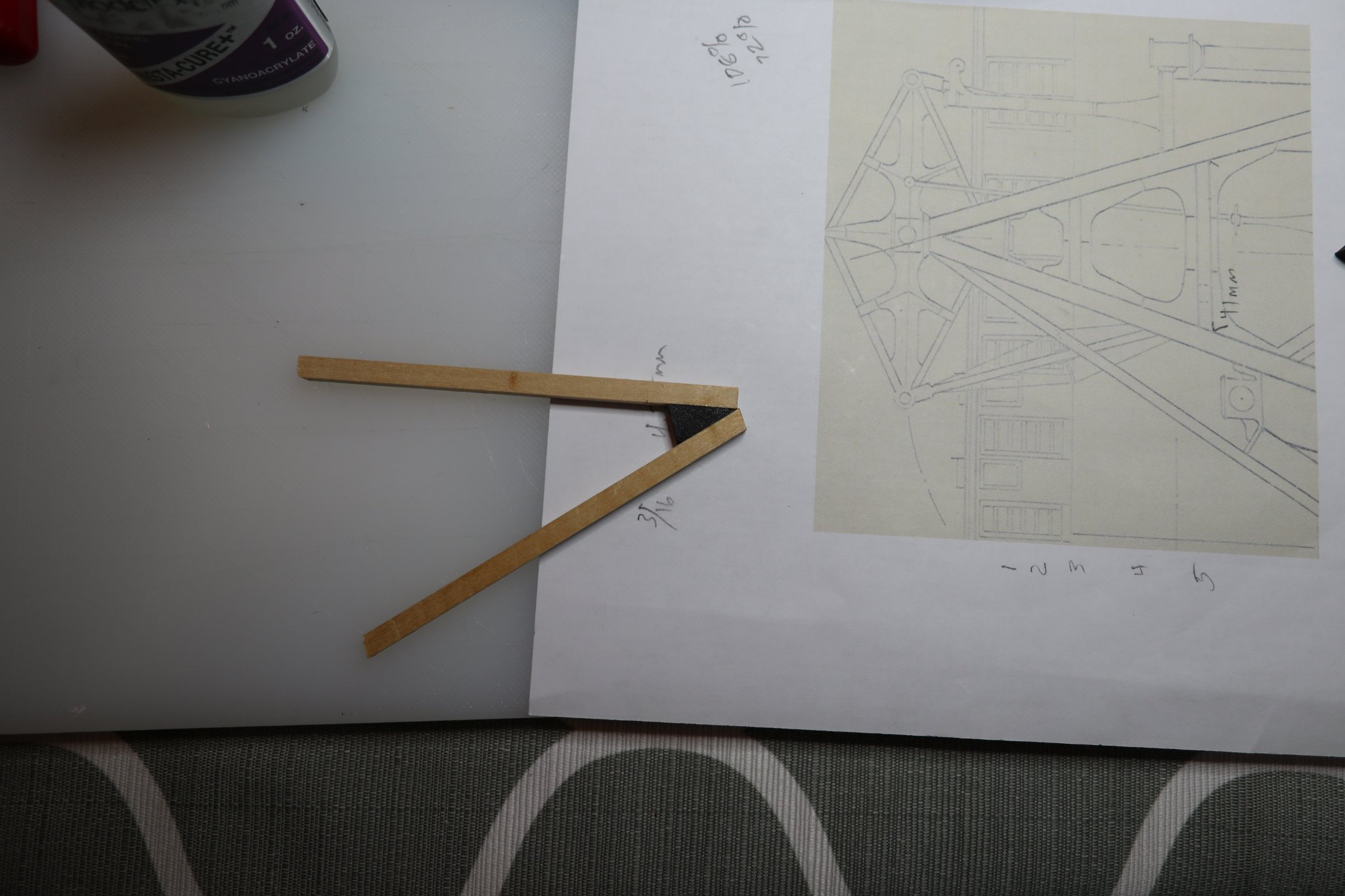
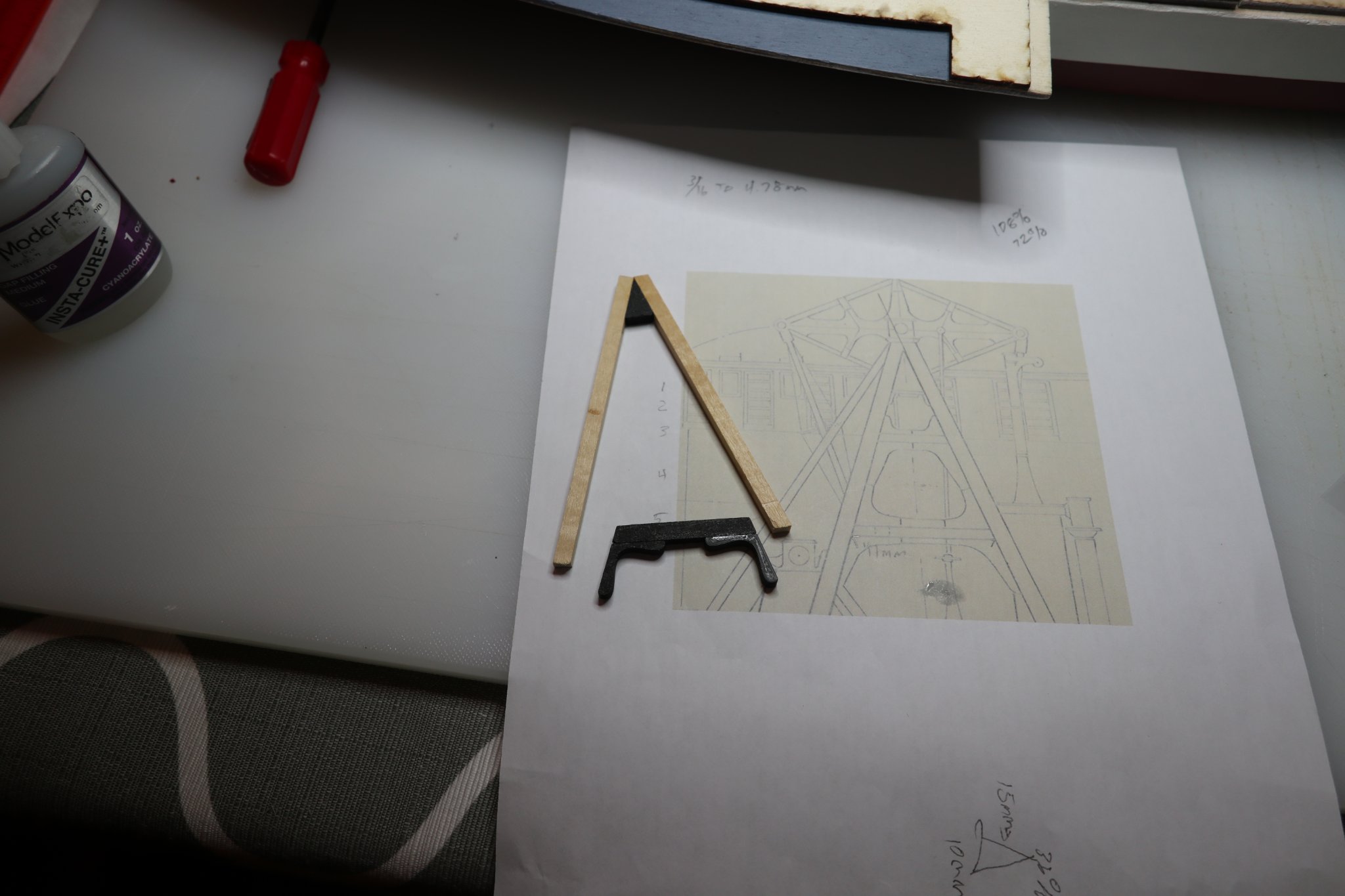
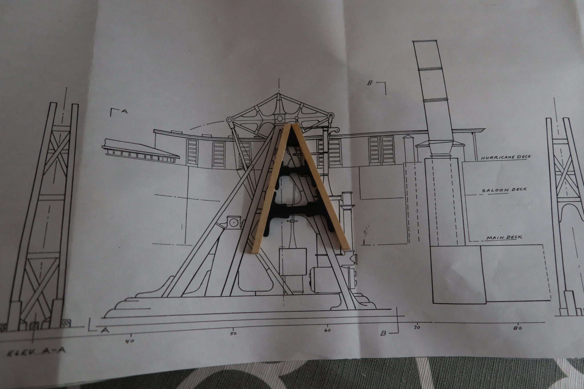
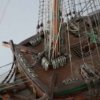
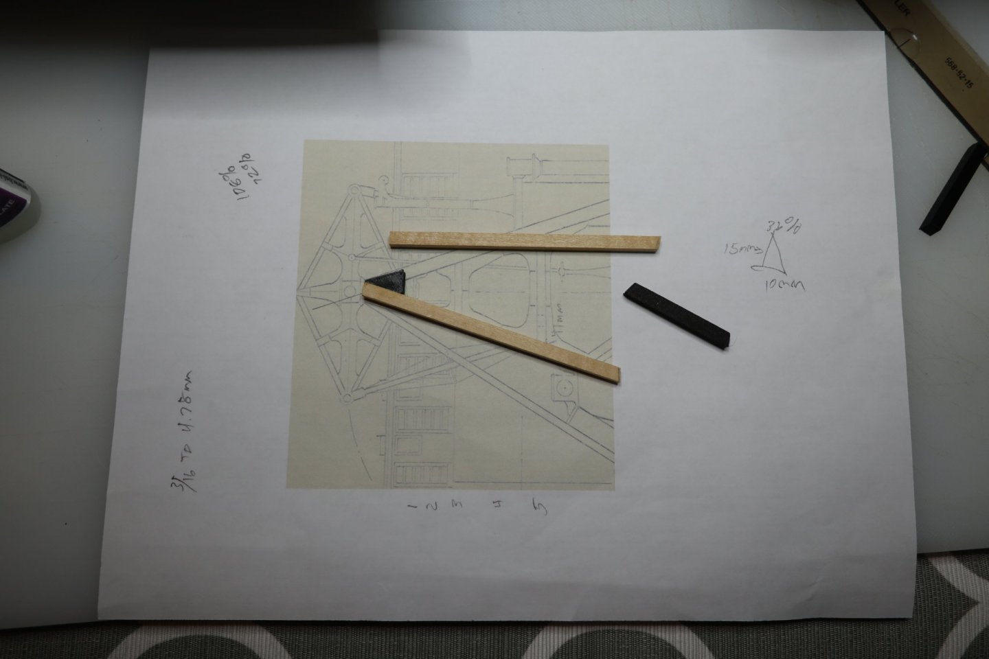
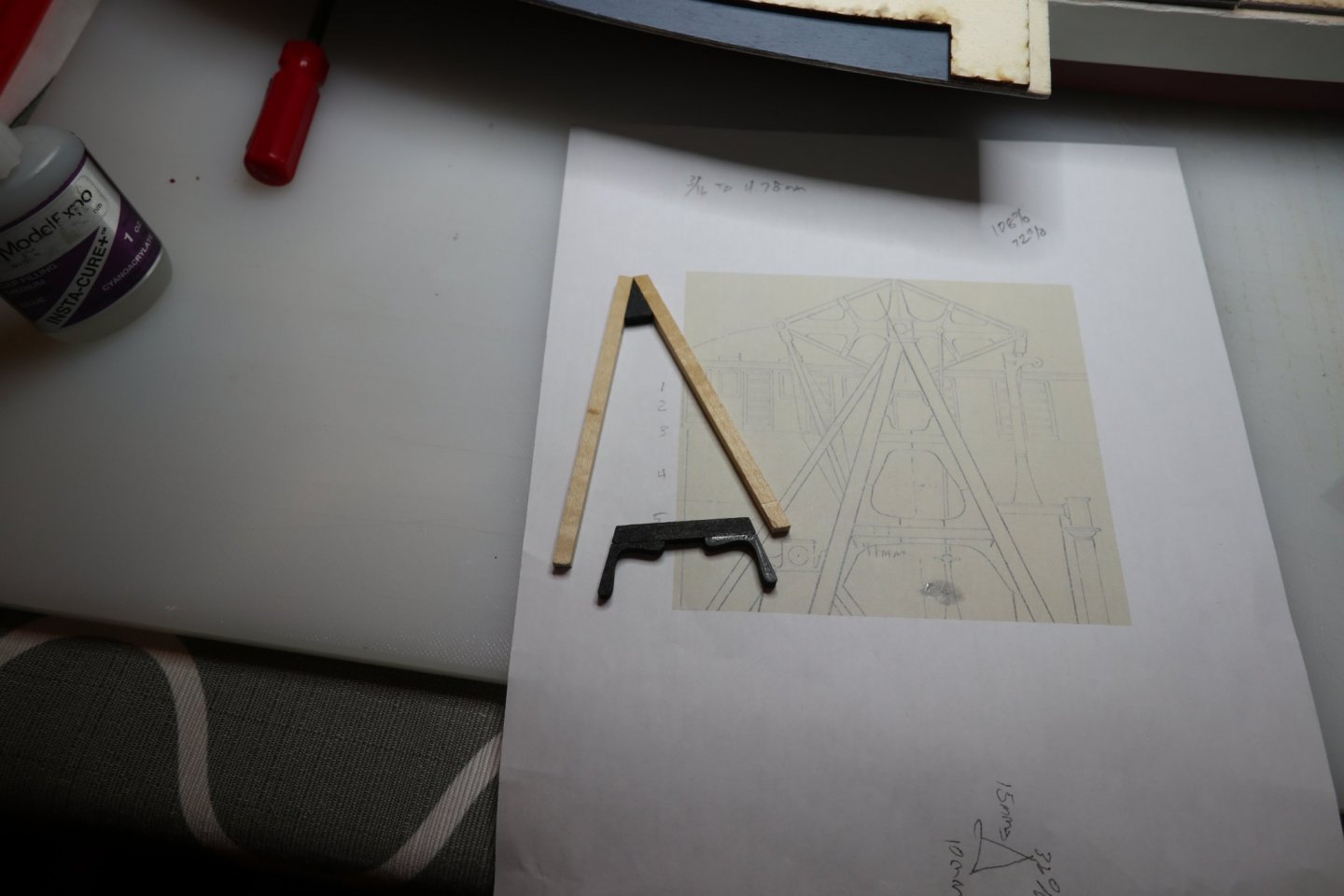
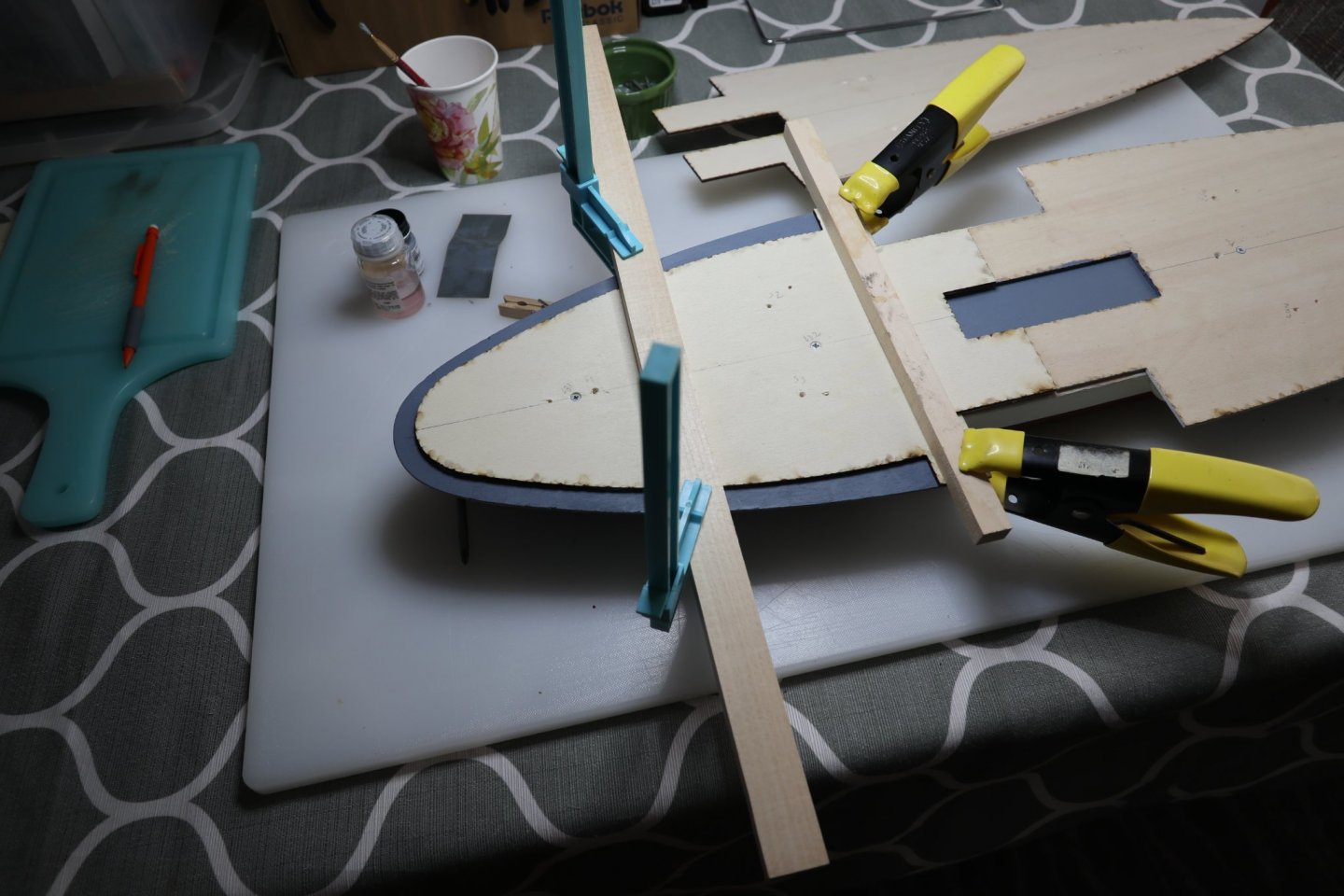
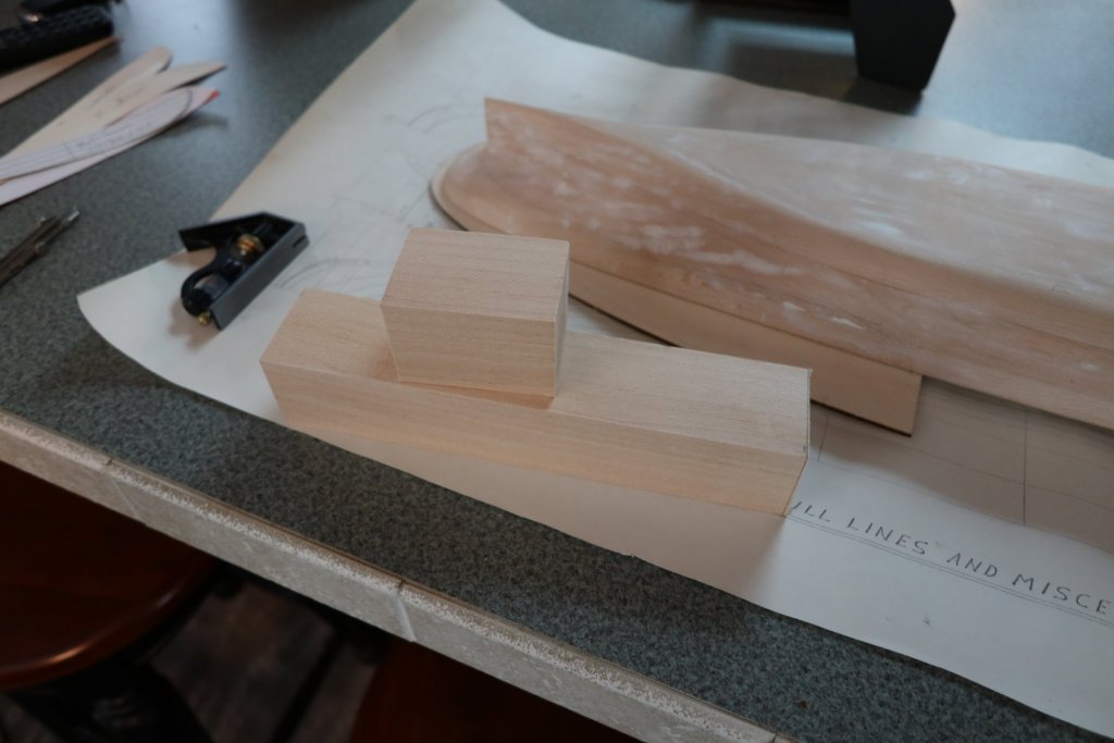
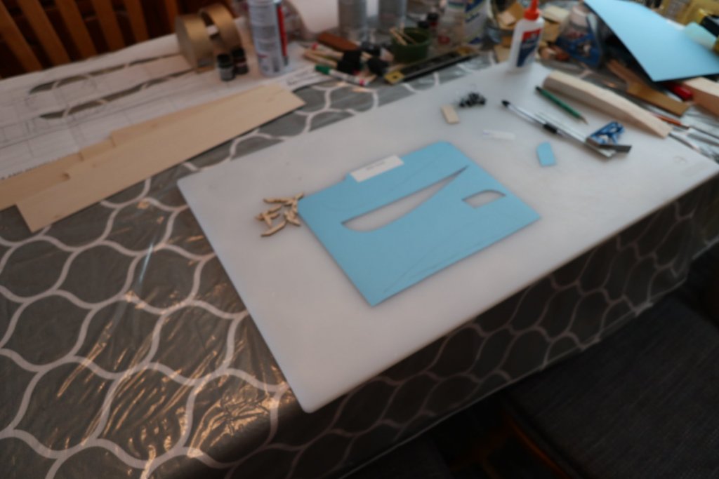
Walking Beam While reading the manual, I was thinking how I was going to handle this piece. I decided to incorporate 3D printed parts to simplify a couple of parts, so here's what I have so far. I printed the triangular piece where the 2 beams meet and glued them in place. I printed the cross beams and supports and glued all of that together. I think the two outer segments came out fairly well. I set one of the parts on the plans. The manual says that a lot of the engine is below the main deck level, which we do not have access to because of the solid hull. I thought about removing some of the material, but with my luck, I'd have to buy another kit to fix a major error. So, my engine will be my representation of whatever is above that line. I'm currently a bit confused by the cross bars on the end views, and will have something figured out in a few days. I'd love any thoughts/ideas you might have. I'm also going to take another look at Dan's engine. He did a nice job with his.


-
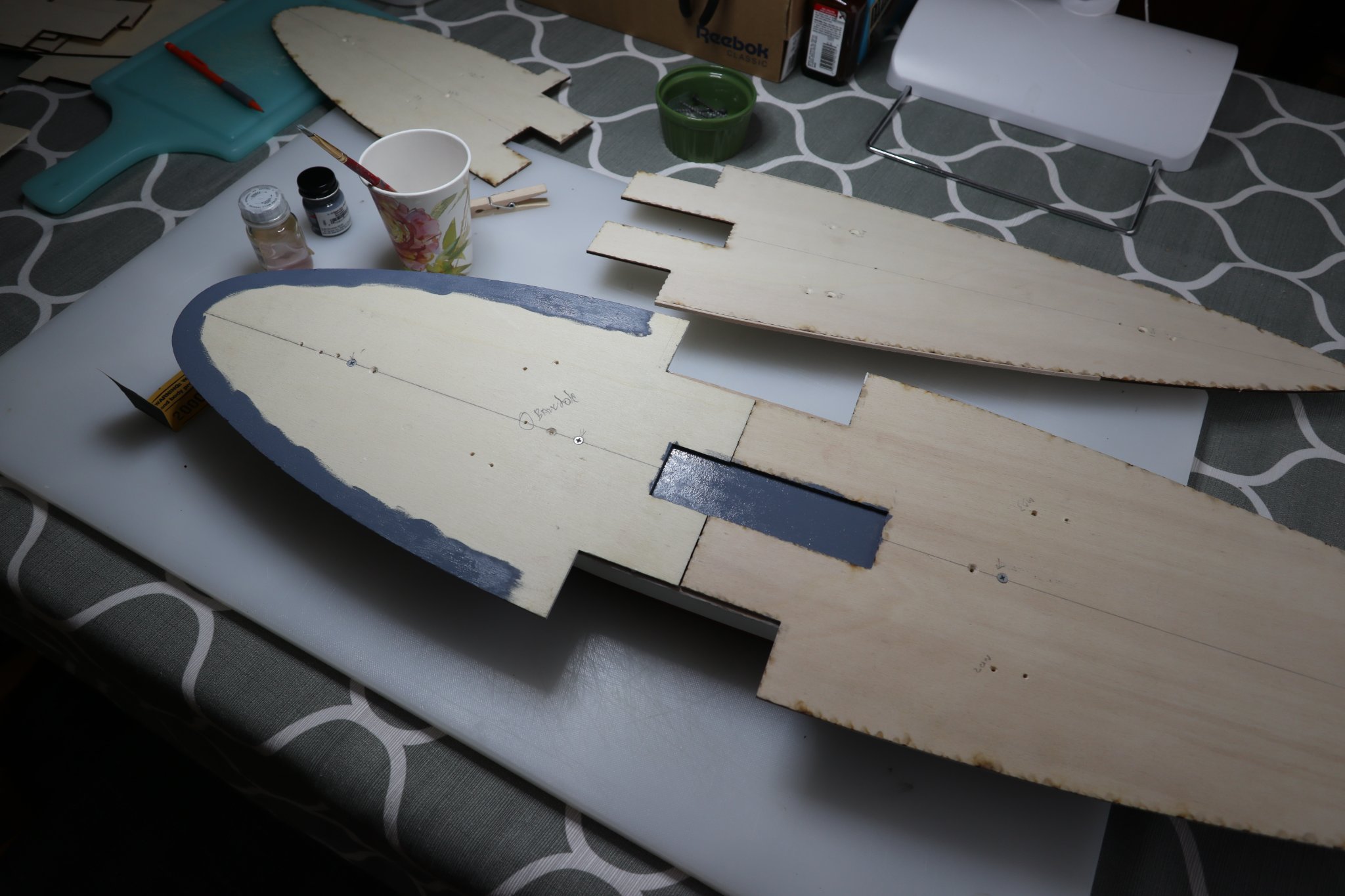
Main deck to saloon deck Sorry I was gone so long. 2020 was a drag. I hope everyone made it through the year successfully! I installed the main deck back in this post. I followed the directions to paint the outer edge of the main deck aft grey, then install the Ladies Saloon Profile, Lower. So, the first thing I did getting back to the model... I missed the center mark by a 16th or so. Glued it down off center and all. I will (hopefully) be able to make corrections if needed, so no big deal. I checked/read the manual for the 1000th time, and it said "Other structures that you may want to build at this time are..." So, I decided to take care of the 3 or 4 smaller sub assemblies then return to the decks. These decks are scaring me a bit I guess. Will return soon!

-
All, I have truly slacked this year. I let the Portland intimidate me. Every time I looked at it, I thought of how many ways I could screw it up. Everything has been on the table all year, and is getting packed up again tomorrow. I promise to get back to it in 2021 (Thanks VTHokiEE for noticing that error!). Have a great AND SAFE holiday season!
-
John, Your work looks really great!
-
John, I'm looking at your window trim work. It's incredible! I hope mine comes out that clean. You are right about the Portland, but it is one of the best looking paddlewheelers I've ever seen. I'm going to be one proud dad when this one is completed! Maybe this log will attract others to the Portland and BlueJacket.
-
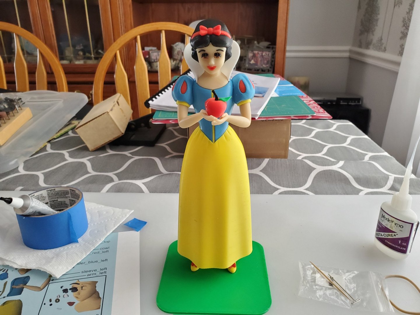
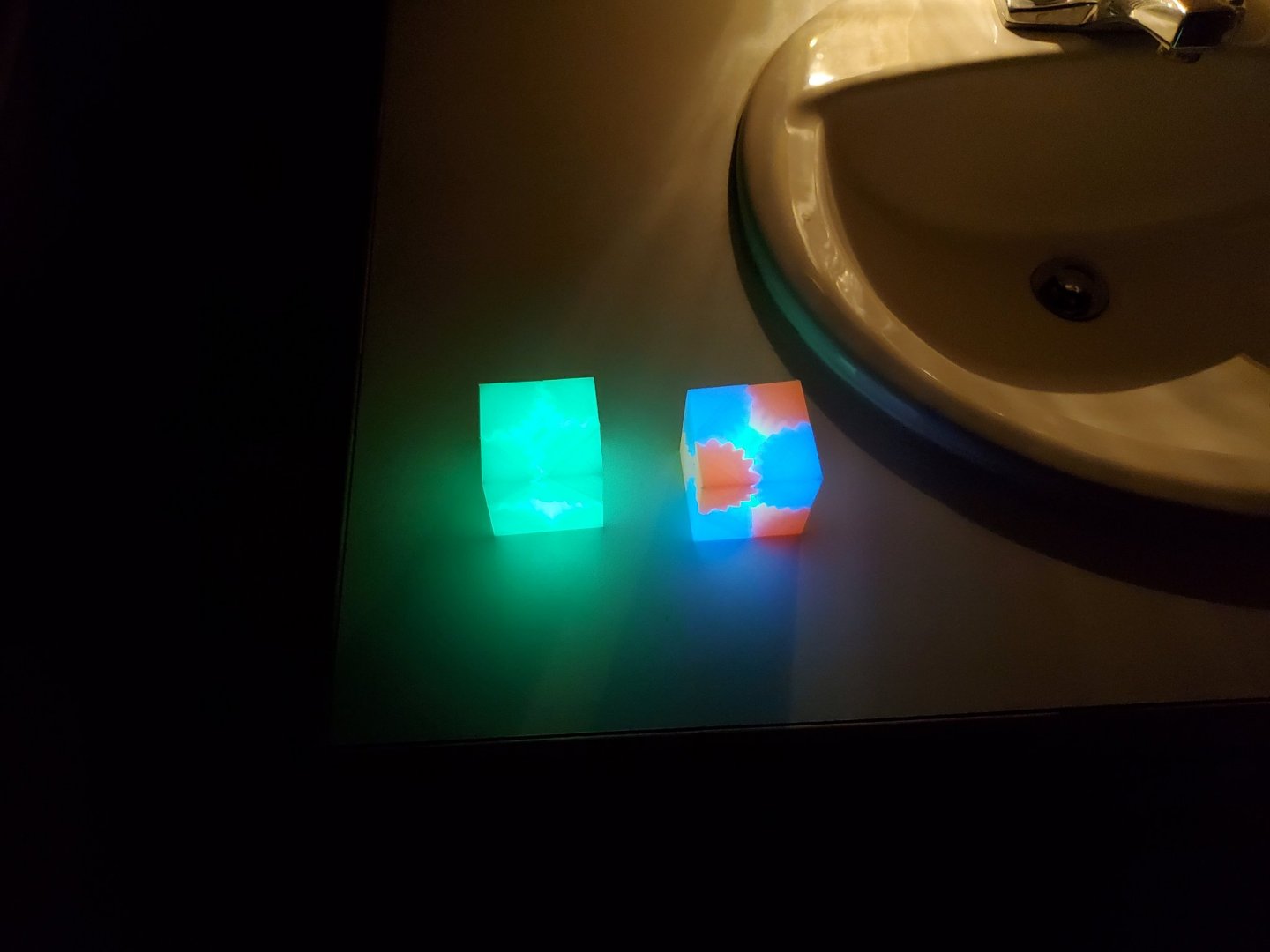
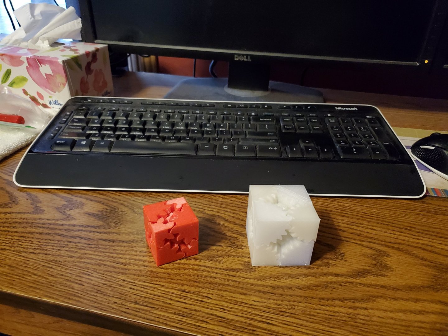
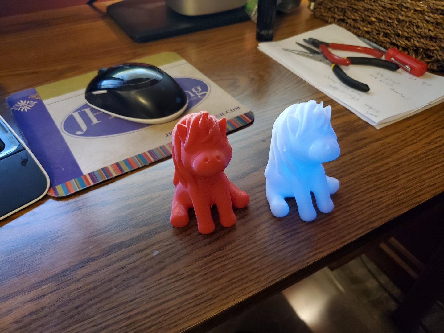
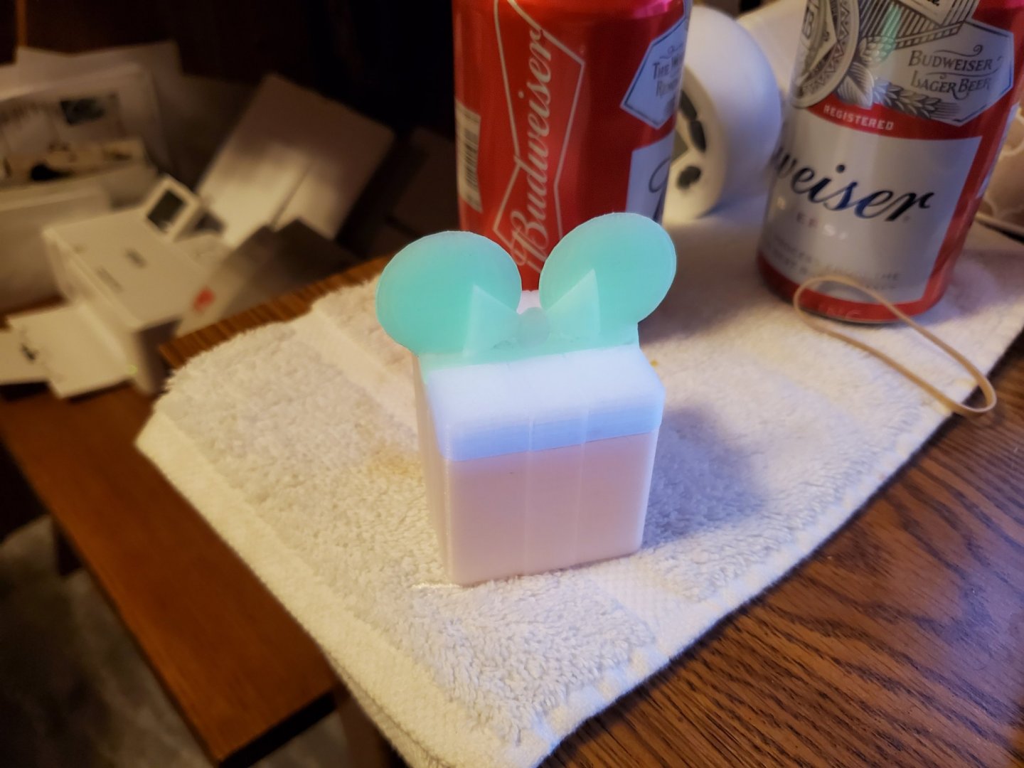
John, The skylight looks great! I've been reading the manual that came with the new model, but after reading your post, I'm going to check out the manual from the original kit. I set out all of my stuff to get back to building, but needed to be sure I wouldn't have to put it away for any Easter family gatherings. I plan on starting up again next week! I have been tying up a lot of time with a 3d printer I bought for my birthday last November! Way too much fun! I may use this printer to produce some parts for the engine.

-
That Portland is spectacular!
-
John, Take care of yourself, and get well. That trestle looks spectacular! In a million years, I might be able to produce a model half as good as what you have produced. Your train stuff is unbelievable. I wish I had the skill you show in your work!
-
Hello! Due to the holidays, we will need the dining room table back to normal, so my Portland is going into dry dock until January. Wishing everyone a great holiday season!
-
Rudder - I followed the directions for the rudder. I did have to trim things more than I expected to get it to fit, but it looks fair. I'm reading up to see what the next step is, plus I'm going to start the walking beam, so I hope to have more posts soon. There is a steering arm that will be added to the rudder at a later date. I'll put that here when I get to it.


-
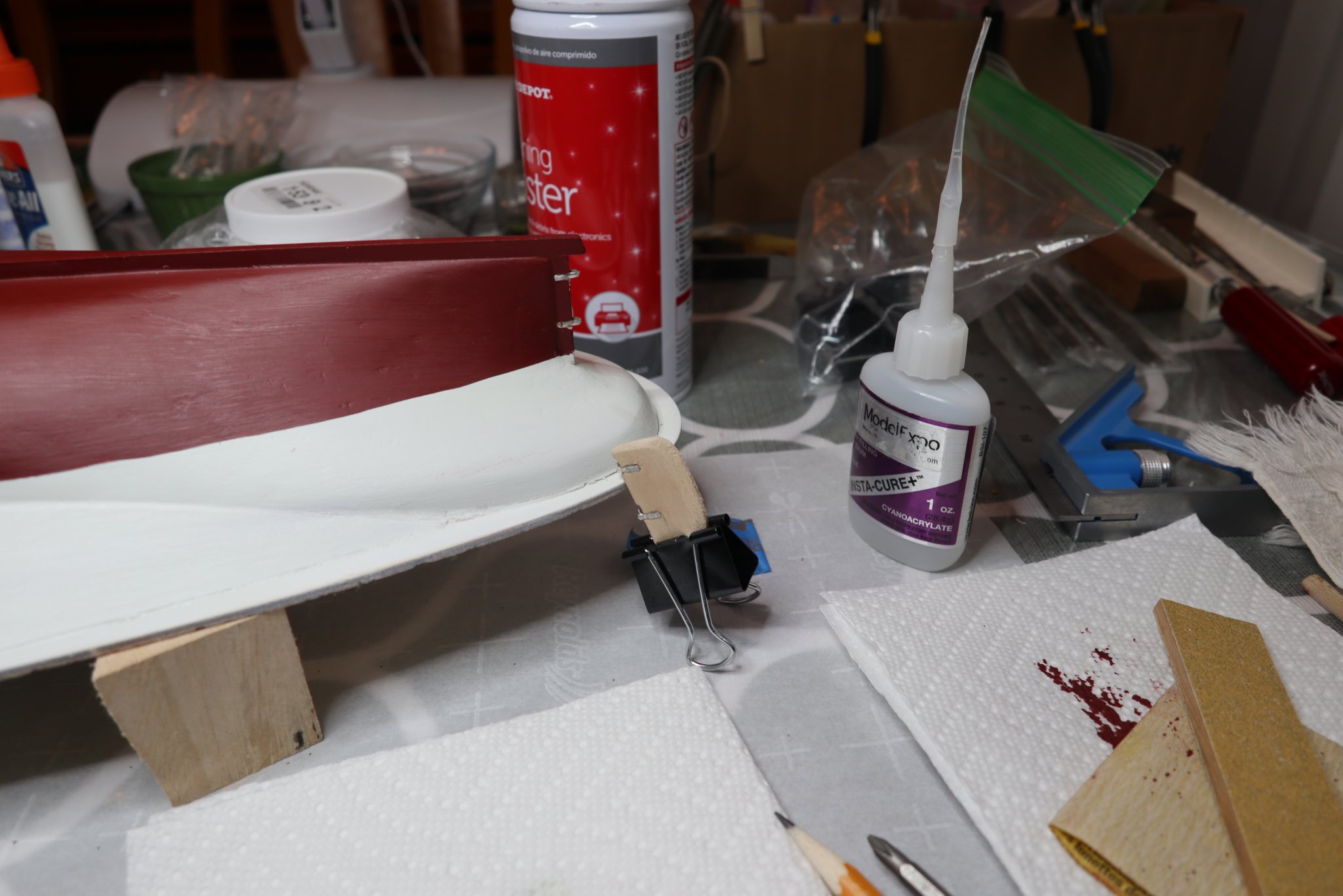
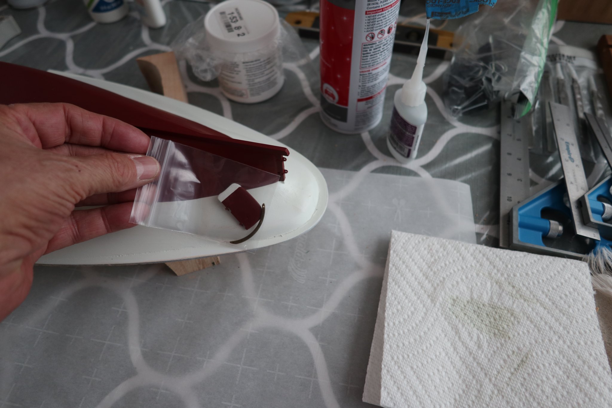
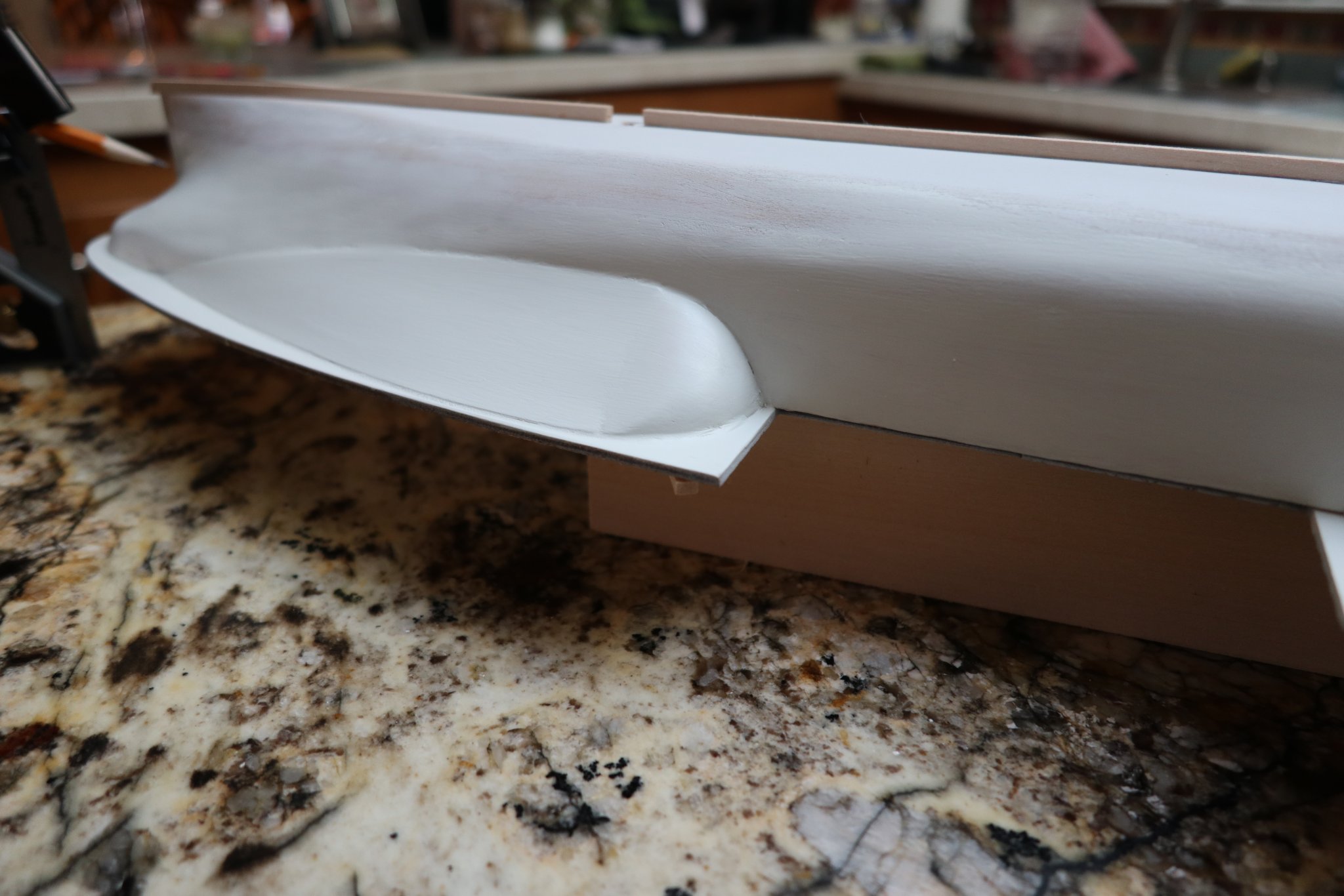
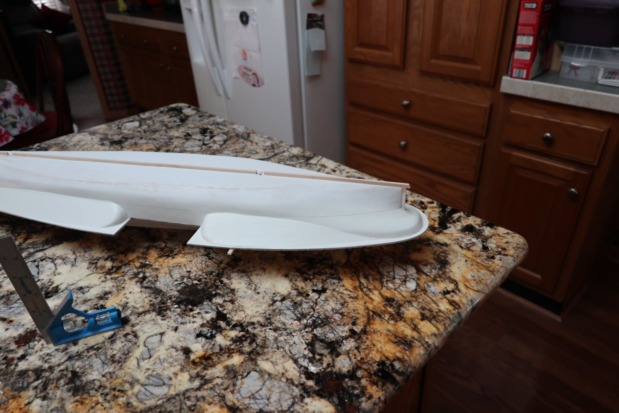
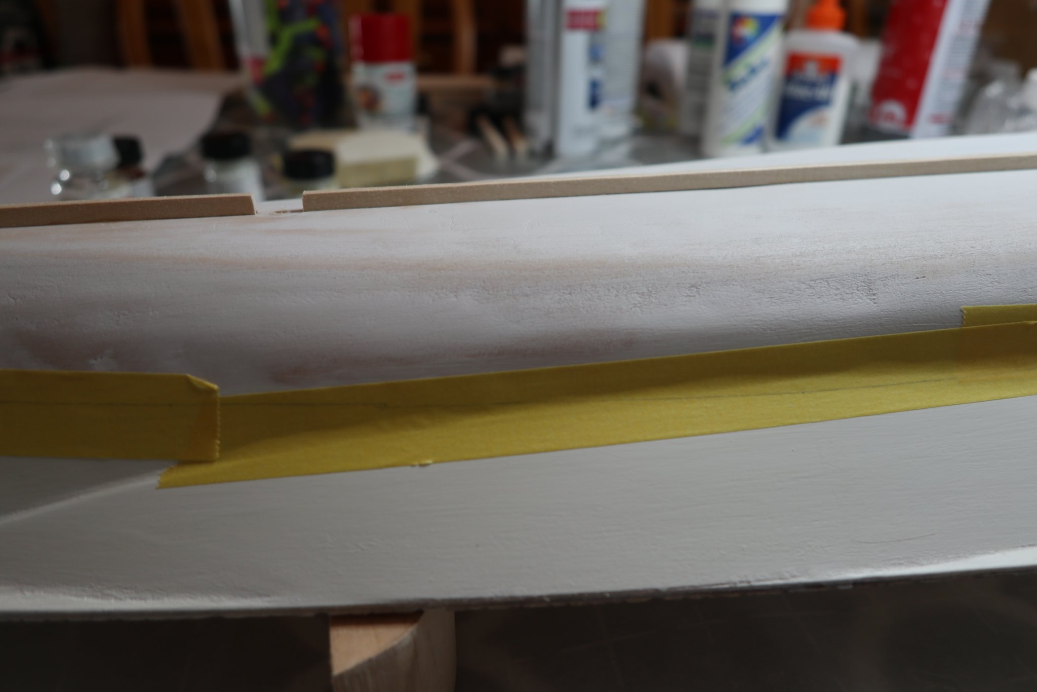
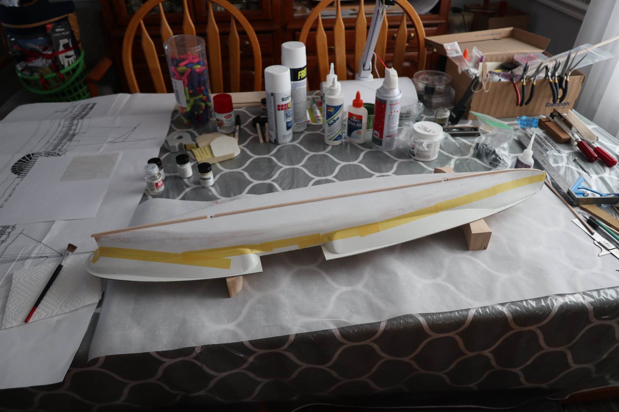
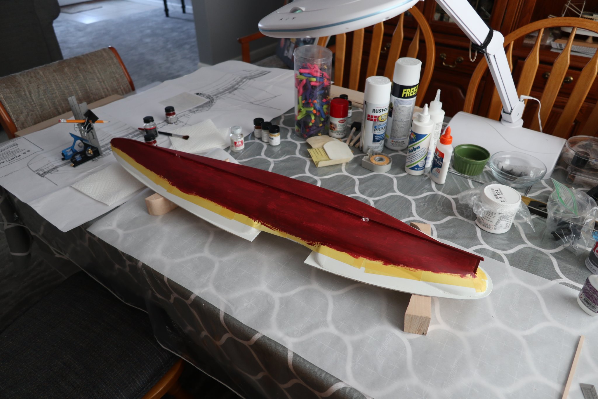
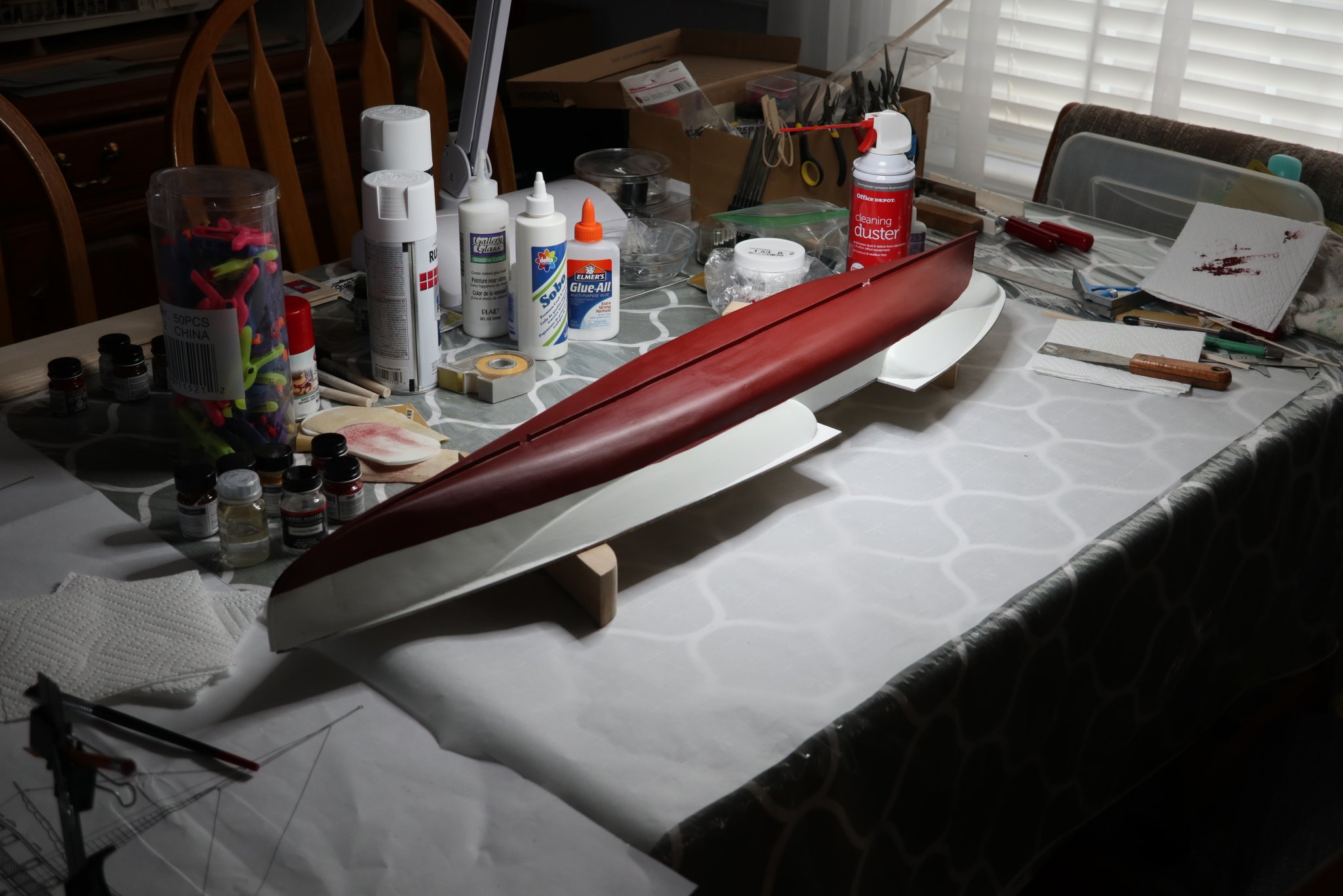
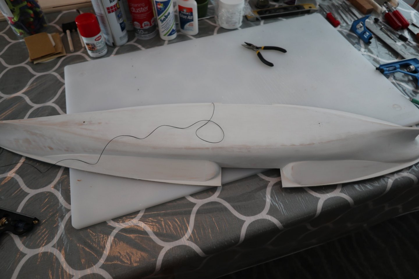
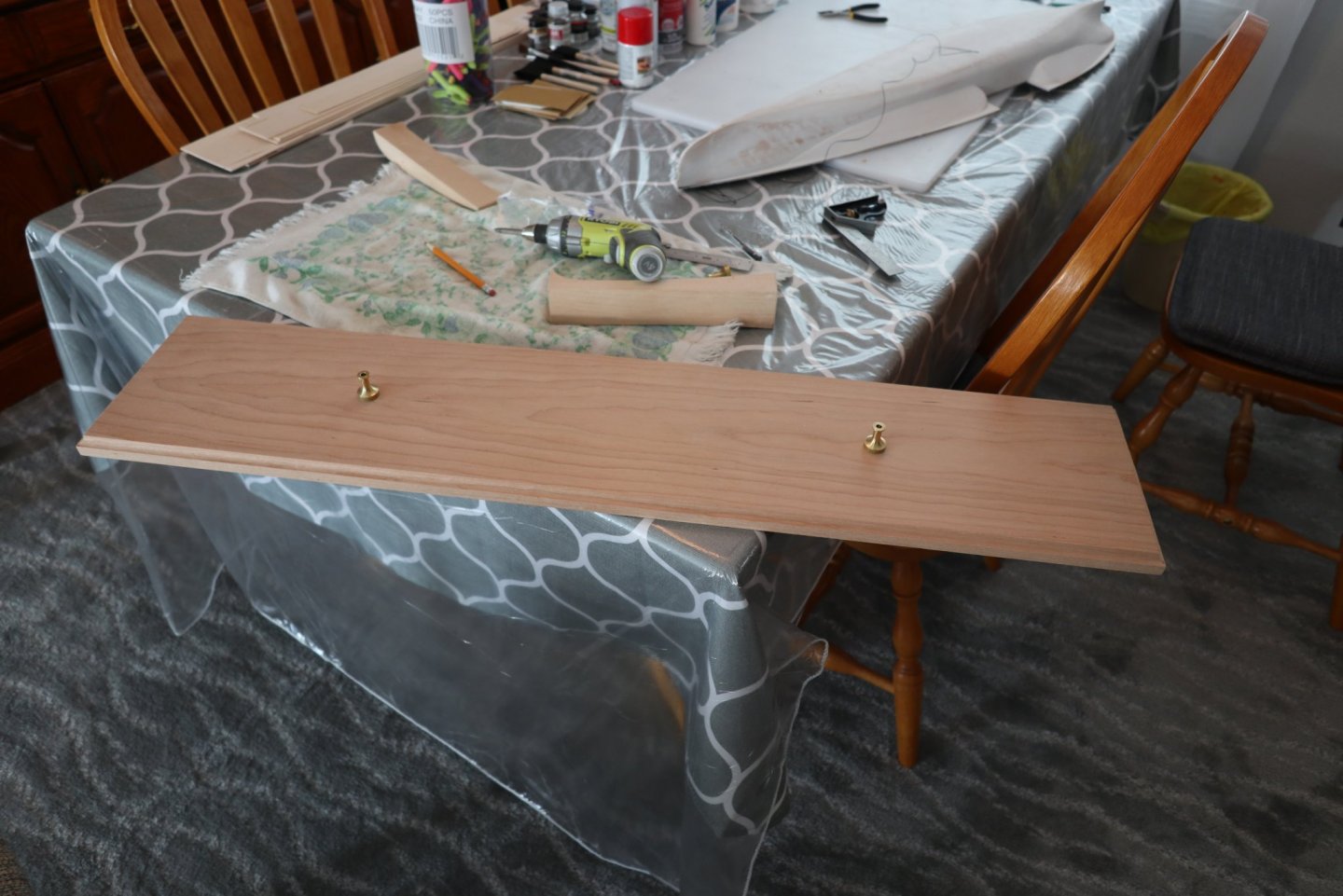
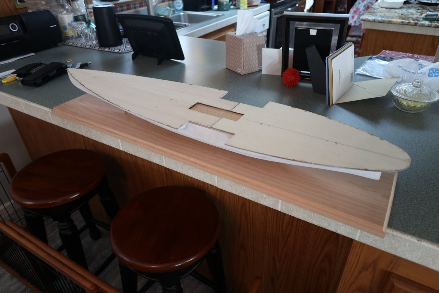
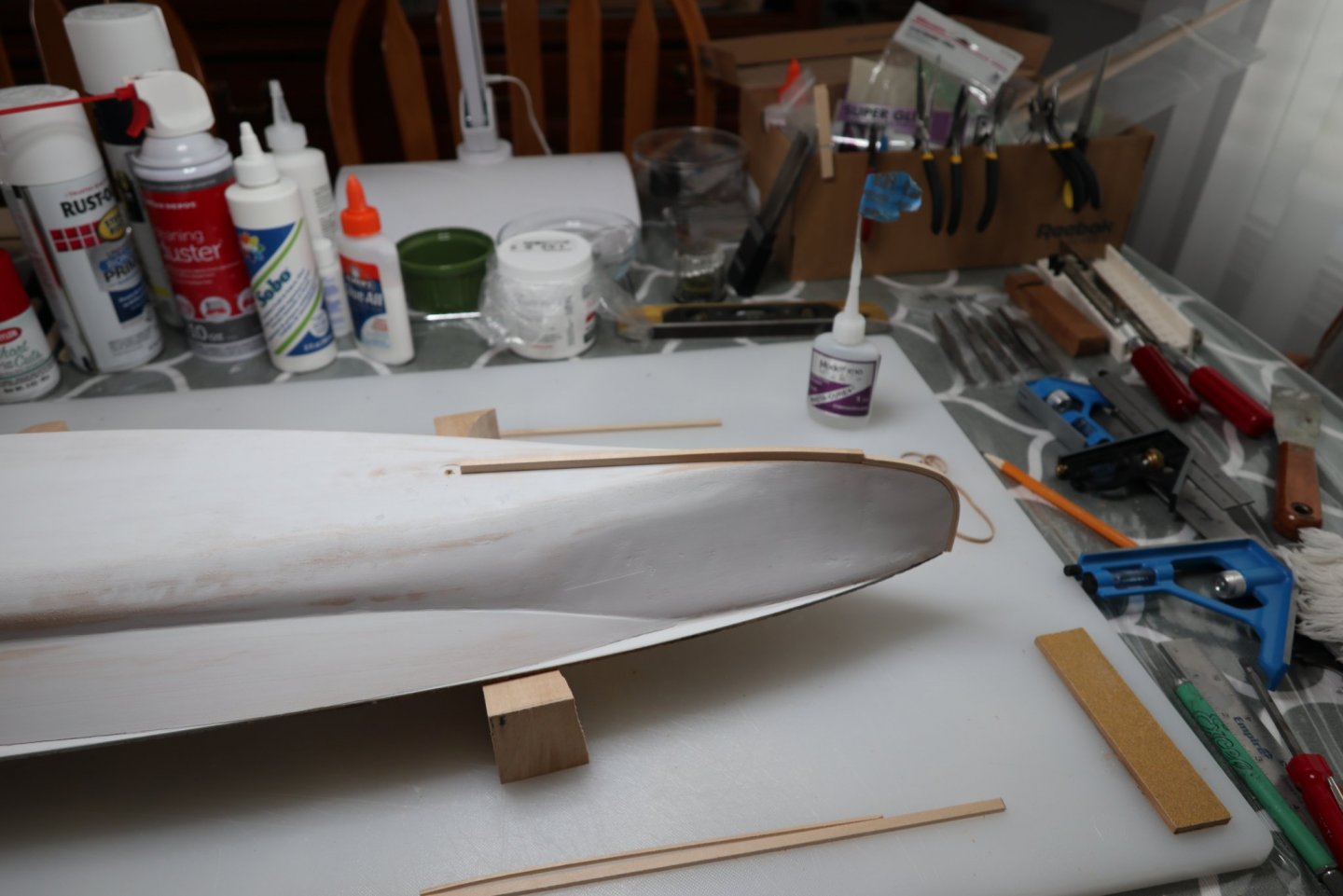
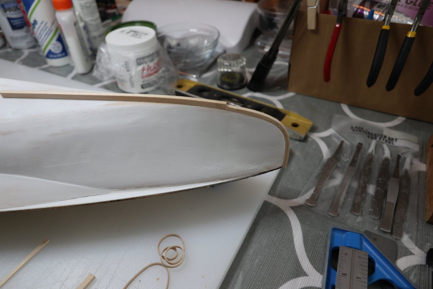
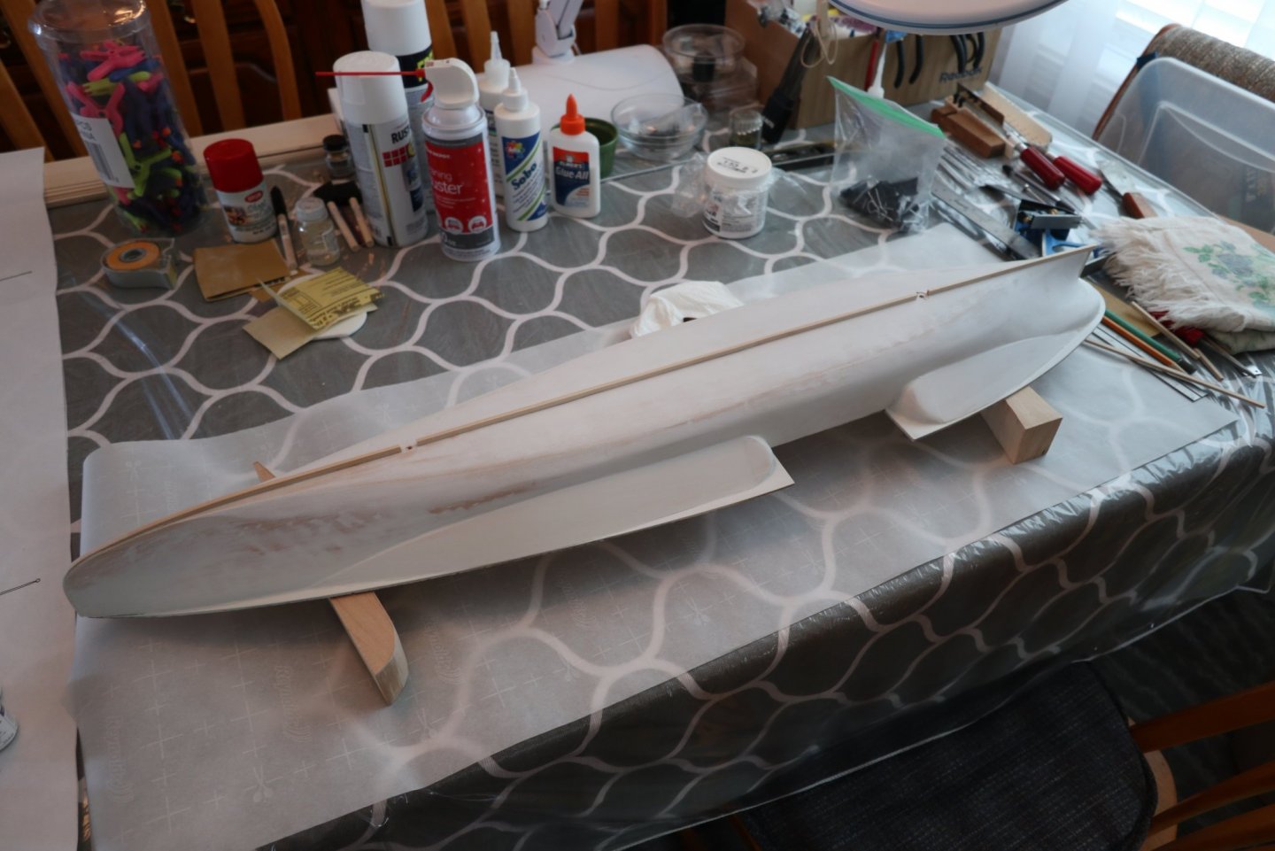
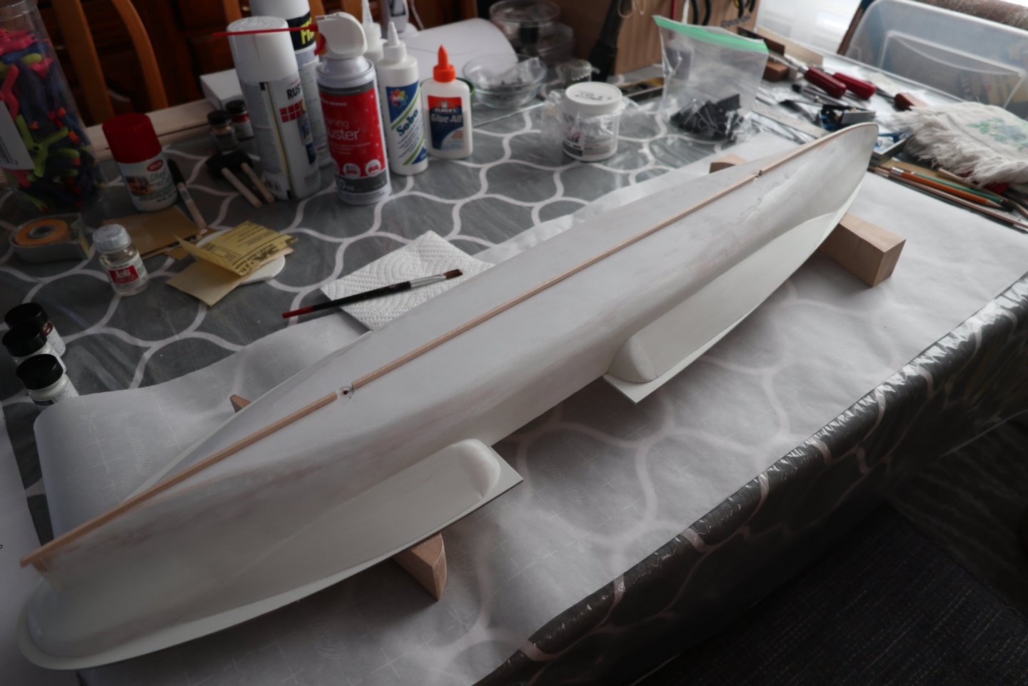
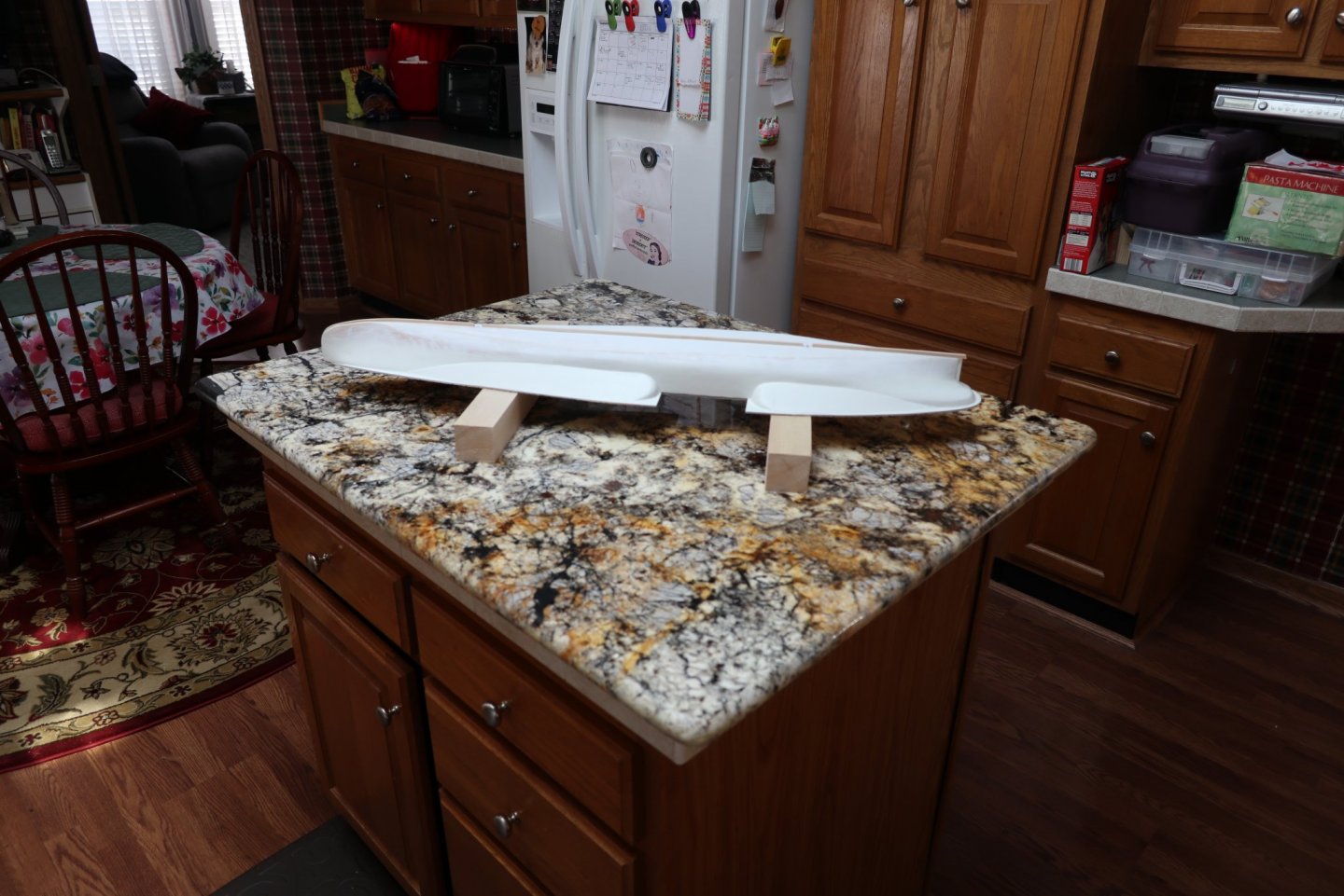
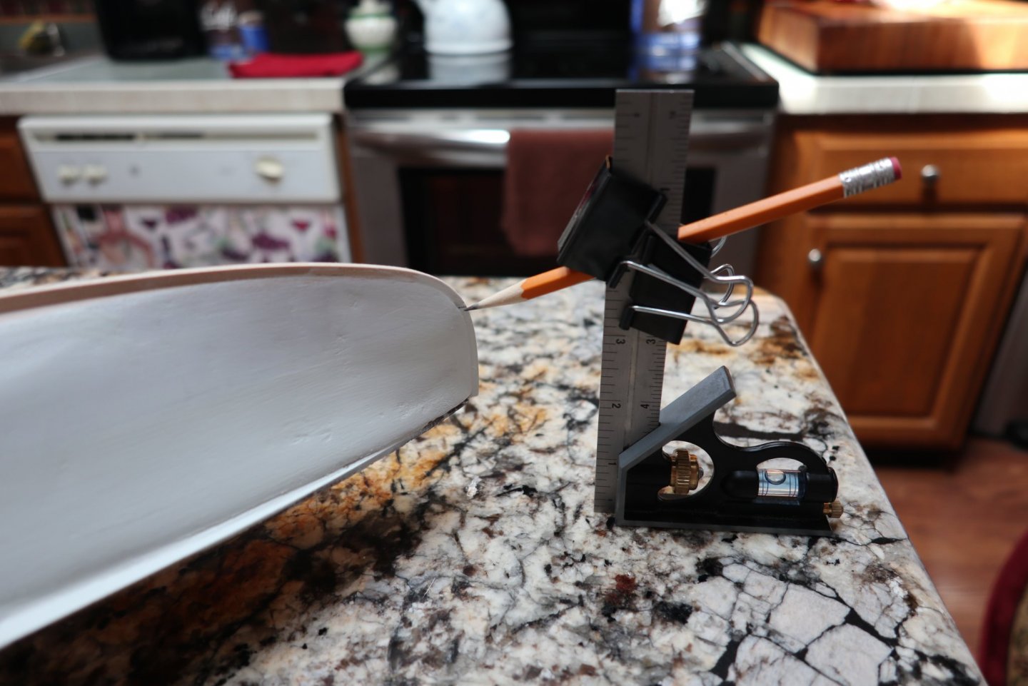
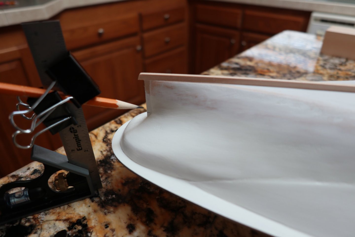
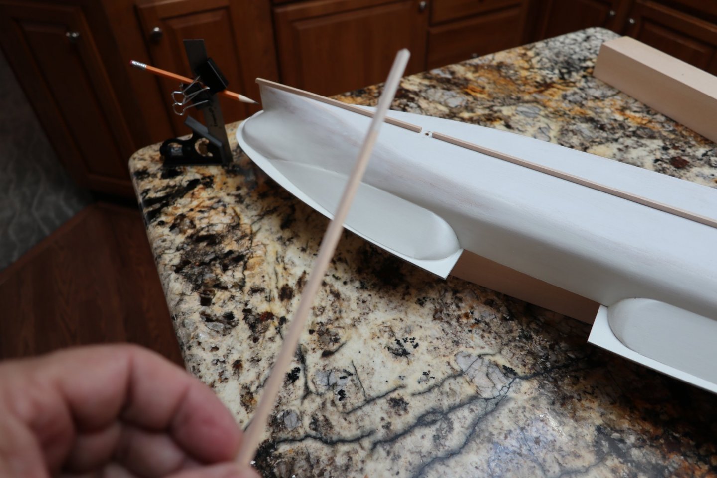
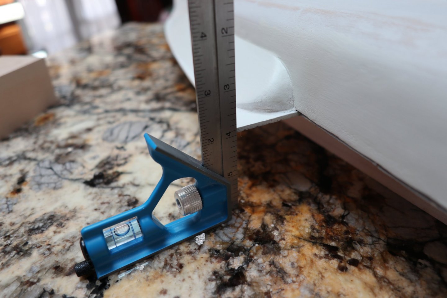
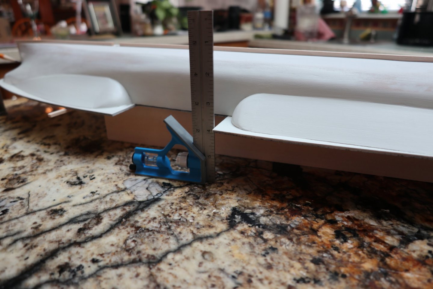
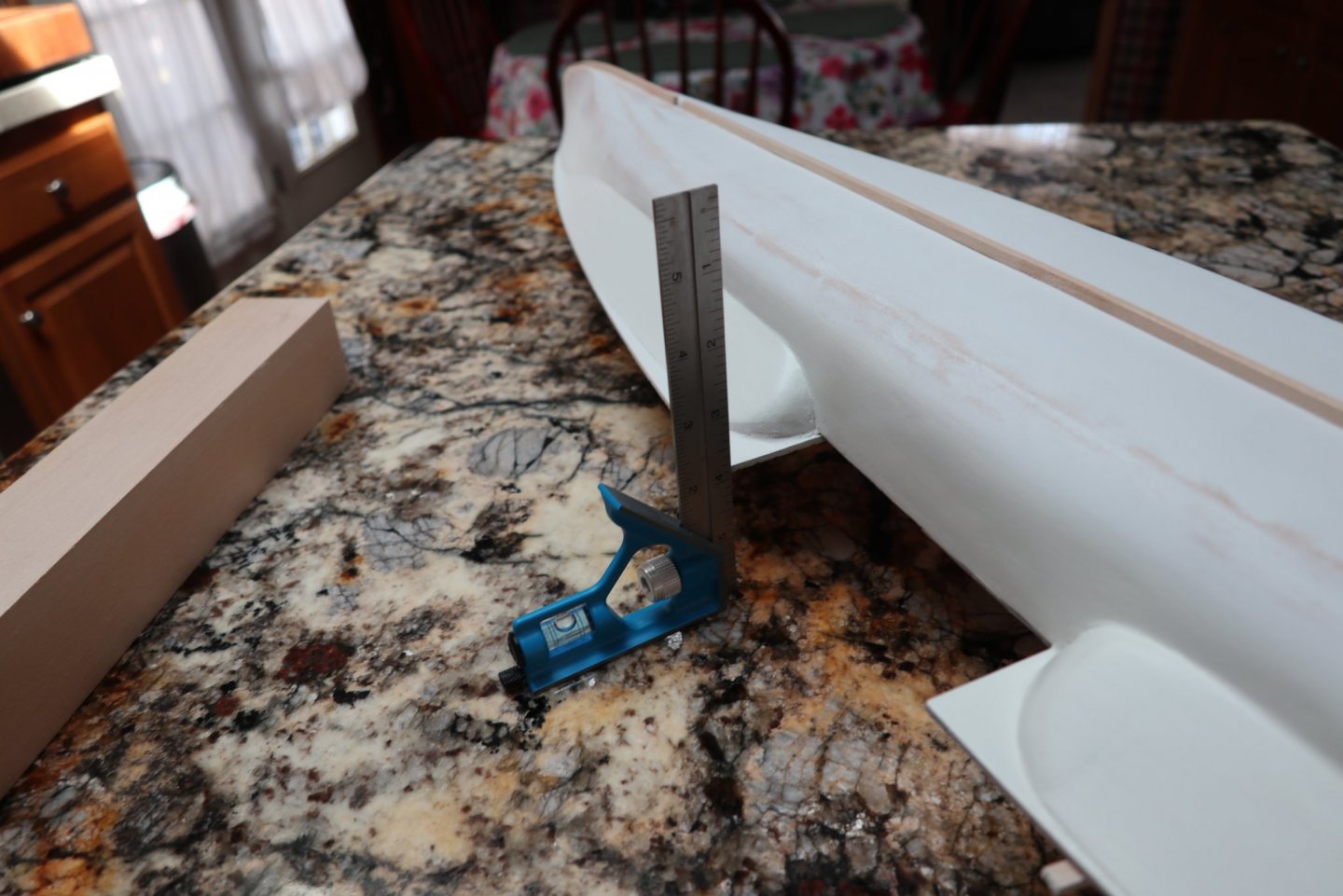
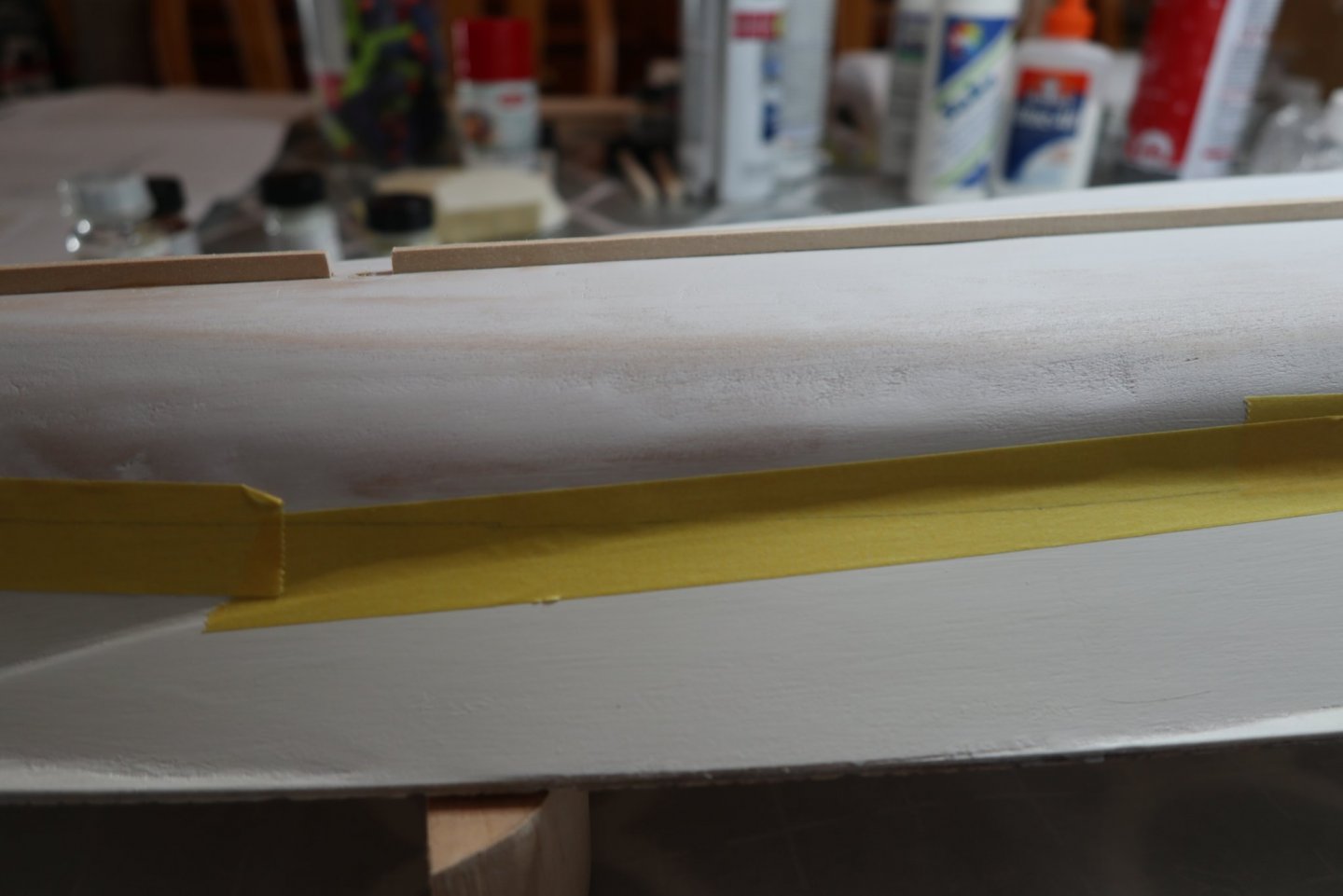
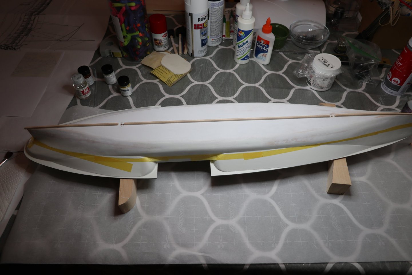
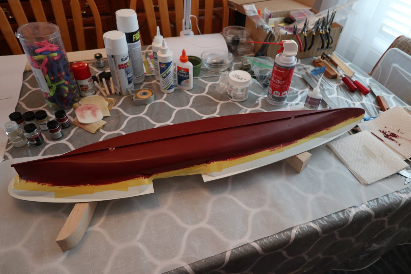
Priming, Hull Paint, Waterline, Keel, Stem Post, Stern Post I learned a lot about painting. Actually I remembered most of it from the past, but it came rushing back while painting the hull. I suck at painting. Spray, brush, you name it, I am no good at it. So here goes... I felt that I did an OK job getting the hull ready to paint. I figured after a coat of primer I'd notice a few spots to fix. Let me tell you, painting the hull showed me how wrong I was. My hull has many more imperfections than I would like to admit to. I'm letting many of them go since they will not be visible on display, but they are there! I did a couple of primer coats using a white spray primer. You may have noticed that I forgot a step. I need to refer to that manual more often. I should have installed the keel, stem post, and stern post first. To get there, I needed to take care of my display needs. I purchased the optional stanchions and display board. Both are exceptional. I knew the keel would need to be removed where the stanchions are located. They recommend and send 3 stanchions for the Portland, but I want to try only 2. My thought is I could set it up for 2 and add the third later if needed. I pulled out the display board and decided how I wanted the boat to sit on it. I drilled holes for the stanchions. I used my string to find the center of the hull. I set the boat on the stanchions where I wanted it to sit, lining up the center as close as possible. I then pushed a screw up through the stanchion to mark where the hole would need to be drilled in the hull. I drilled that 1 hole on the center line, and mounted it to the base. I aligned the 2nd hole, and marked it with the tip of a screw through the stanchion. I unscrewed the hull, adjusted the 2nd mark to the center line, and drilled the 2nd hole. I remounted it all to see the results. Check out that display board. It is really top notch. I'm sorry I didn't take any photos bending the wood around the bow, but I followed the manual and here's what I ended up with. Using the plans, I tried to have this part meet the keel where the thickness changes. I don't remember the exact measurements, but the keel is the same thickness until it approaches the bow, where it thins out a bit. I knew the keel would need to be cut out for the stanchions, so I added the first piece. I added the keel between the 2 stanchion holes, and the keel post. Using a sanding block, I sanded this area so the keel smoothly rounded the bow. I left the bow part thicker than the plans show. I may need to resand it later, but I wanted a bit if insurance just in case. You can see the final product below: I used calipers to measure where the waterline is on both ends of the boat and marked the hull at those locations. I needed a flat area to do this work, so I used the kitchen island. I liked John's use of a large mirror, but if you saw me you would understand why there are no large mirrors at my house. Using my highly professional Norm-O-Matic waterline marker, version 2.0, I lined my pencil to the mark on the bow. The pencil did not align at the stern. I added the necessary shim to raise the stern to the correct height. That did it. The next step was to make sure the port and starboard heights were the same. I used the square and made necessary adjustments. I went by the deck height. It worked out alright. I drew the line around the hull. Be careful around the sponsons. It felt tricky. If I took a photo of both sides of the boat, the waterline looks "off" a bit. But I think it's because of how I built the sponsons. Not really noticeable, but it's there. I think the first place I heard about Tamiya tape was on Dan's Portland page. Then John mentioned it also. So, I decided to buy some from Amazon. Worth every penny! I don't know how others do the waterline thing, but my thought was to use the tape to cover the line I drew, then mark the line again for cutting. It turns out that the Tamiya tape is kind of see through! So, using a fresh X-Acto blade, I carefully trimmed the tape at the marked waterline. I do not have a photo, but I added a 2nd layer of tape below the first so I wouldn't have any slip ups. So here's the first coat of red, hand painted with the paint I got from BlueJacket. Another plug for them. It is really nice paint. A bit of sanding and a 2nd coat. More sanding, a third coat, and remove the tape! I have a touch up or two to take care of, but in display mode, I'm accepting my work as it appears. Thanks as always!


-
All, Sorry things are going slowly! I got a part time job stocking shelves at my local Walmart. I could walk there if I had to. I'm working 3 days a week 4 a.m. to 1 p.m. After 21 years behind a desk and never exercising, this has been good getting me back into exercise, and I'm getting paid for it! Of course, cleaning up 21 years of sedentary fatness is a bit painful. I painted the hull, so I will post those photos today.
-
Dan, Your Portland came out great! You gave me a couple of ideas for mine. Again, the figures/lighting/tables add a lot of realism to the build, Nice job, and thanks for sharing.
- 29 replies
-
- 1
-

-
- portland
- BlueJacket Shipcrafters
- (and 1 more)
-
Thanks Dan!
-
John/Dan/other portland builders, I have a question. Reading the manual, it says that most of the walking beam engine is below the main deck. According to the blueprints, we only need to build what shows ABOVE the main deck? I'm figuring the final engine size to be 4.5 to 5 inches tall? Does that sound right? The instructions say to show as much detail as you can. It would have been fun building more of it. I'm painting my hull now. More sanding, more filler. I hope to have a new post in the next week or so. Like I said, I'm also working part time too. Any thoughts on the walking beam process?
-
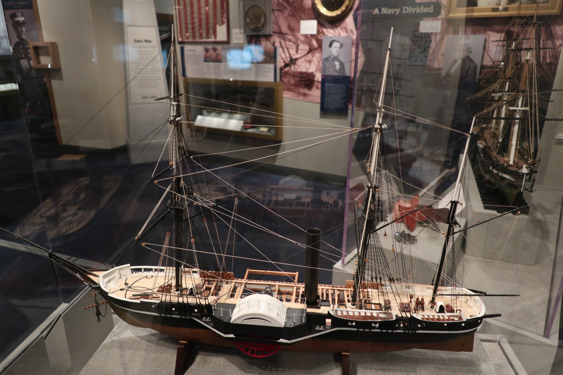
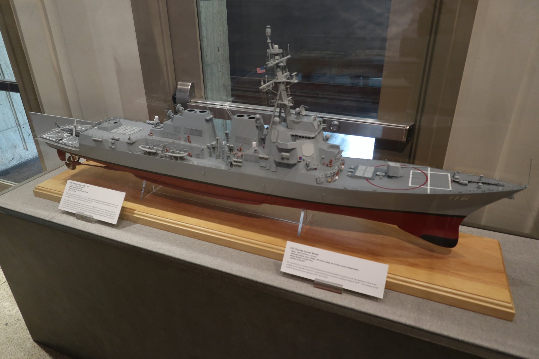
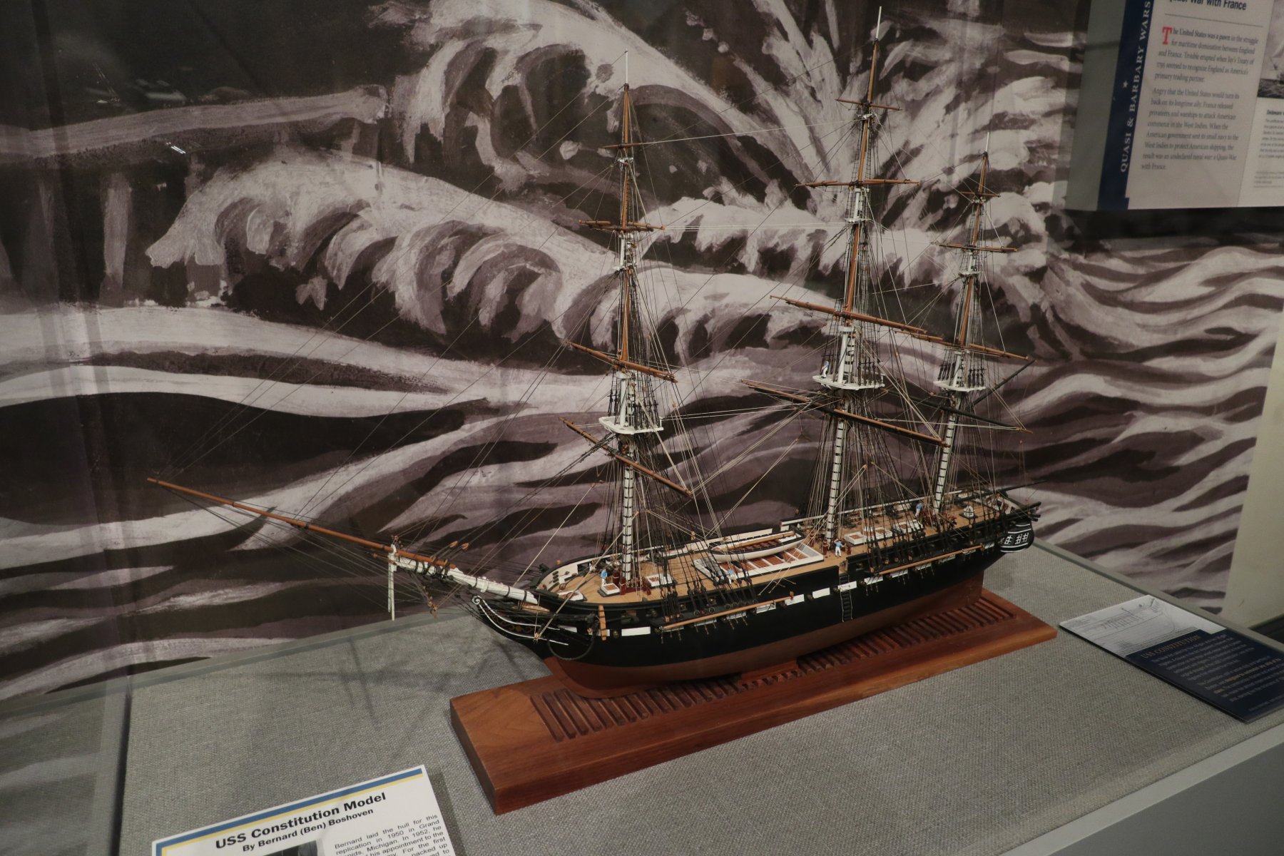
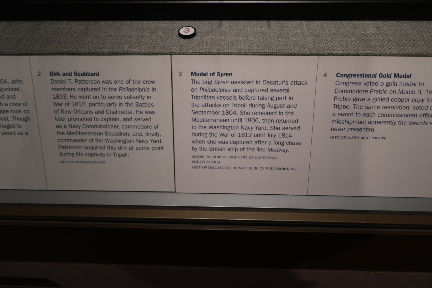
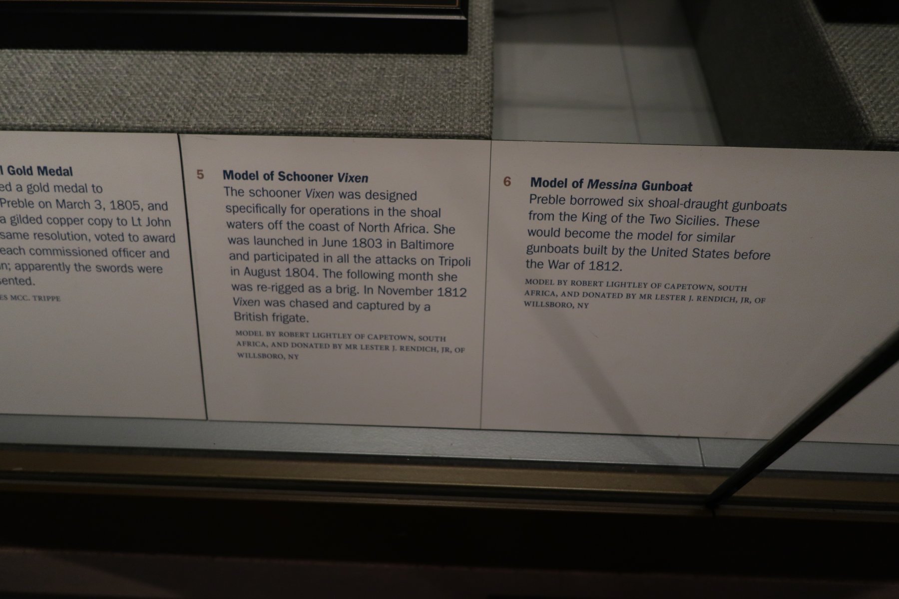
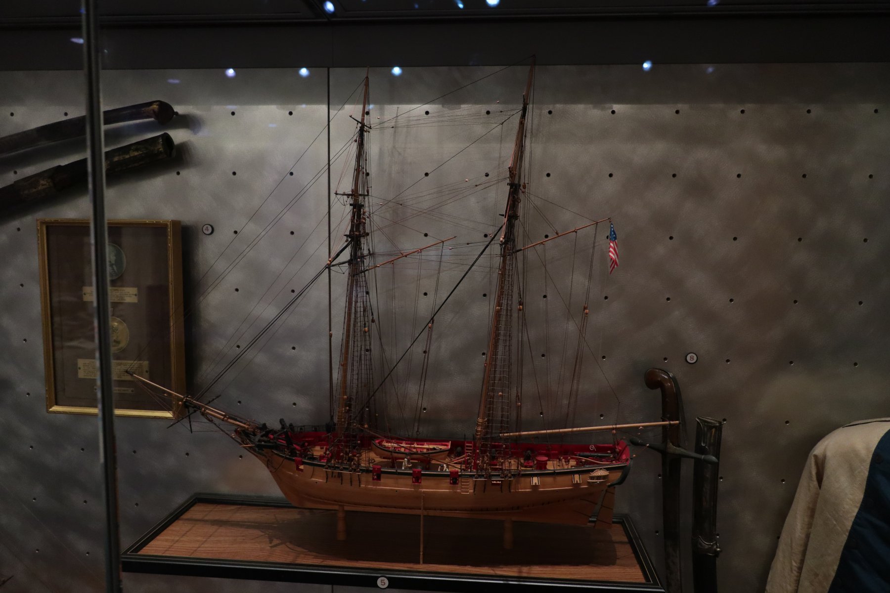
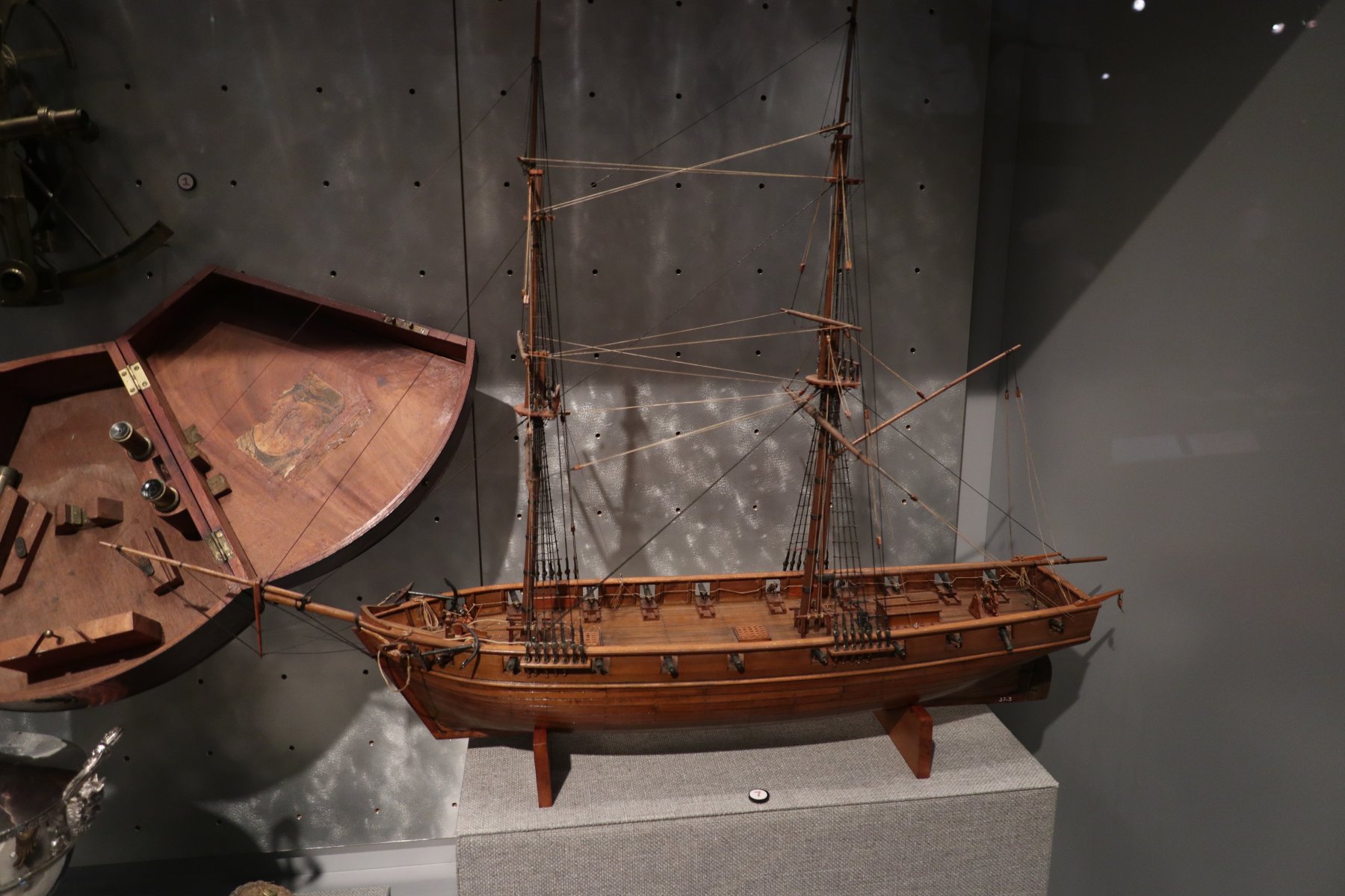
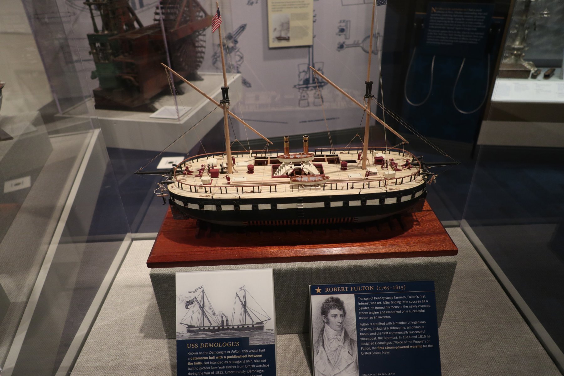
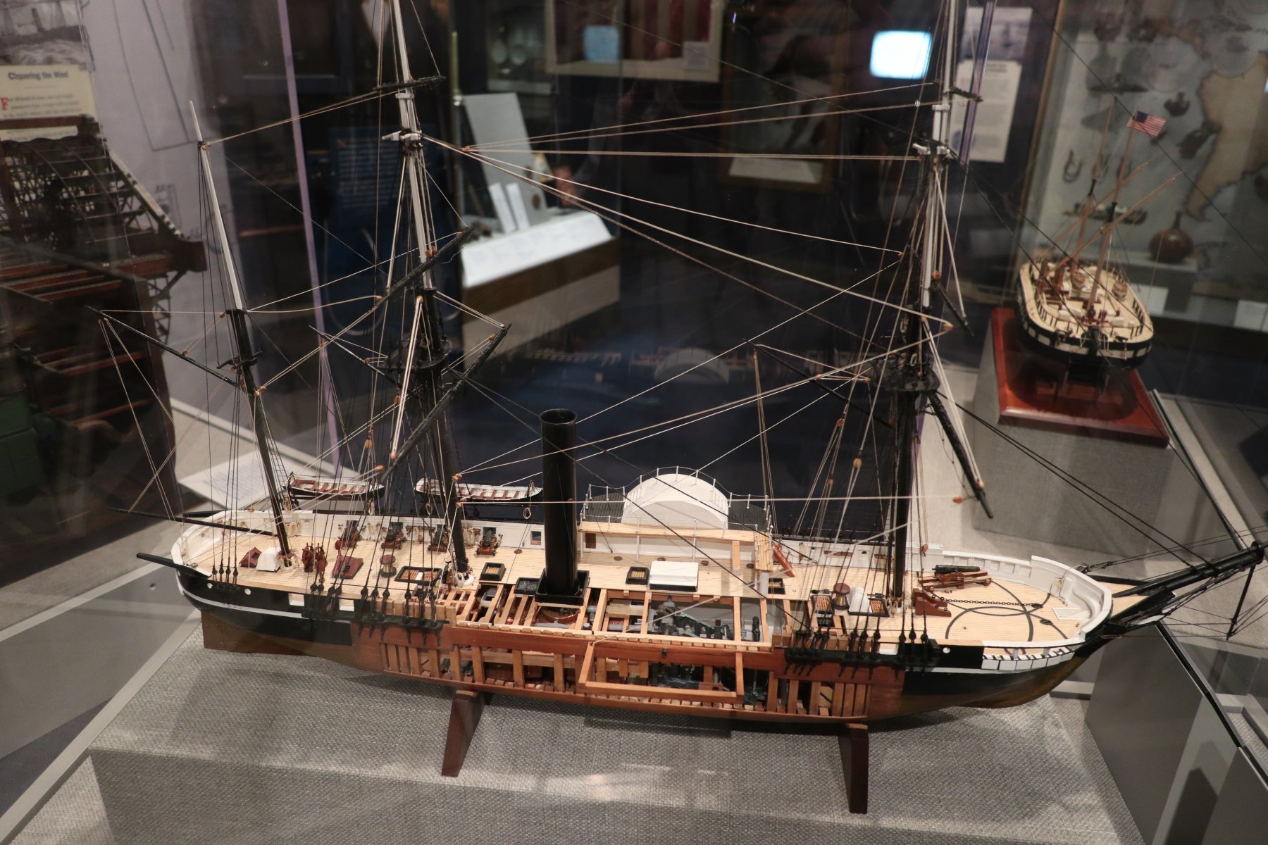
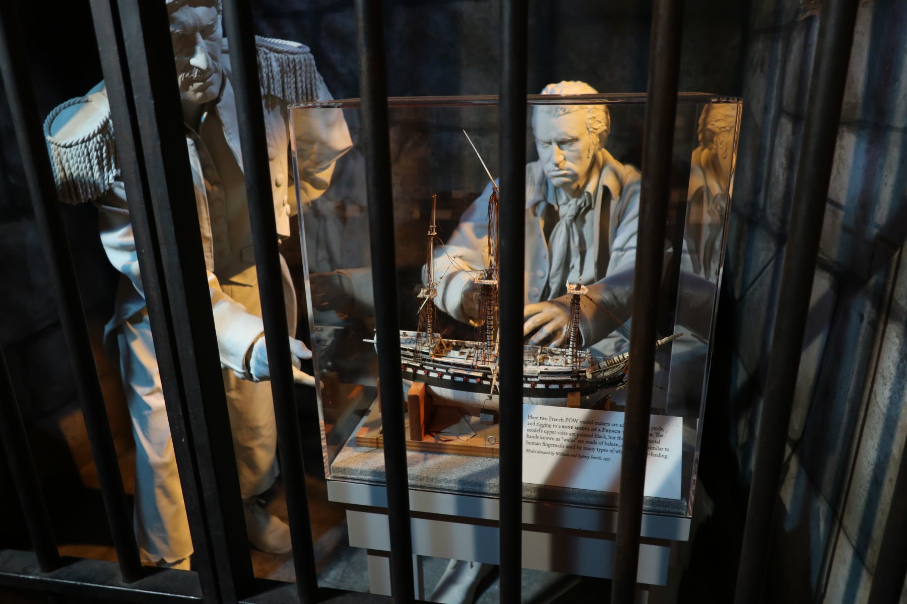
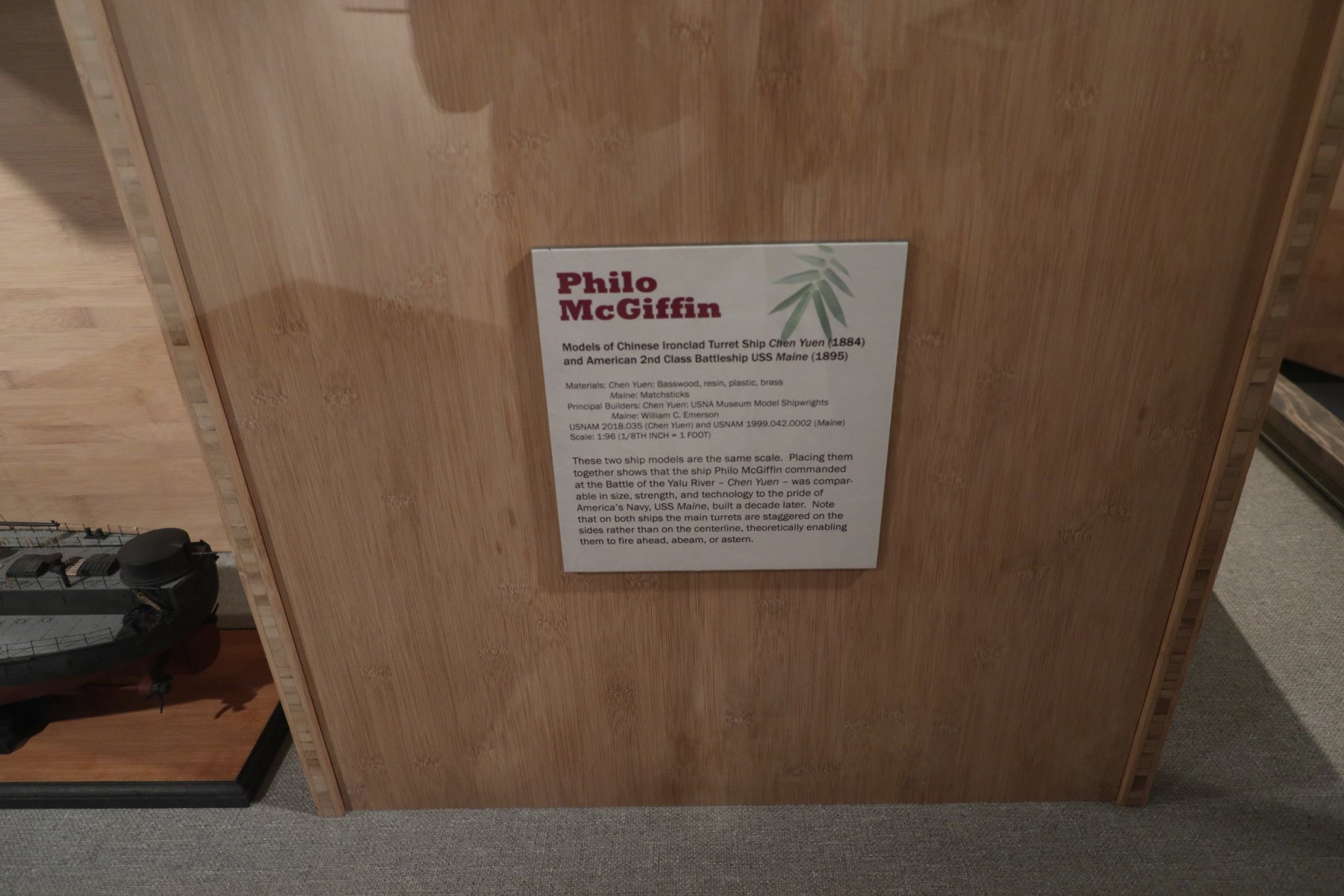
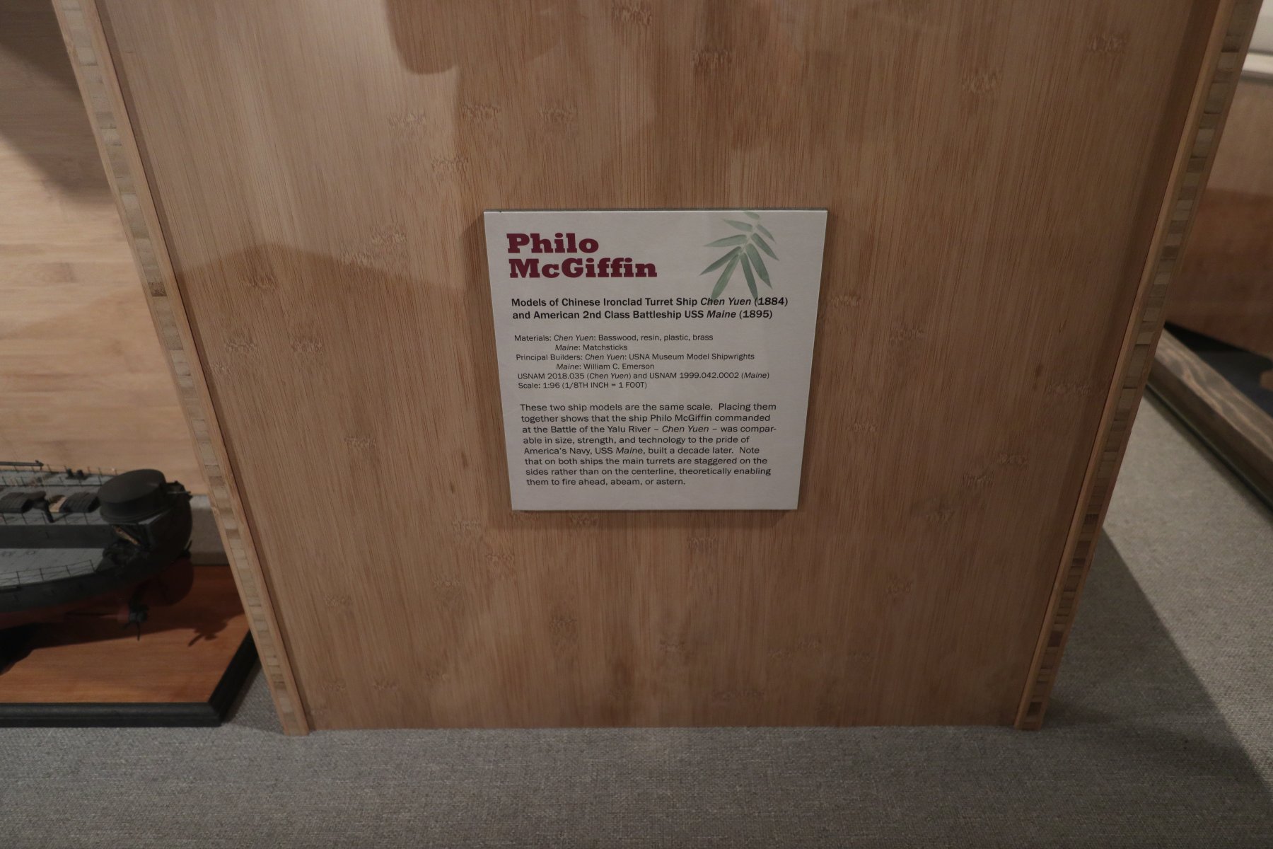
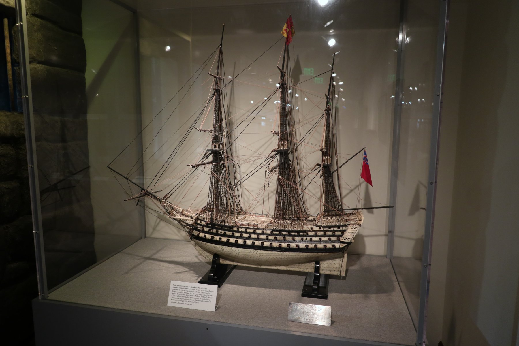
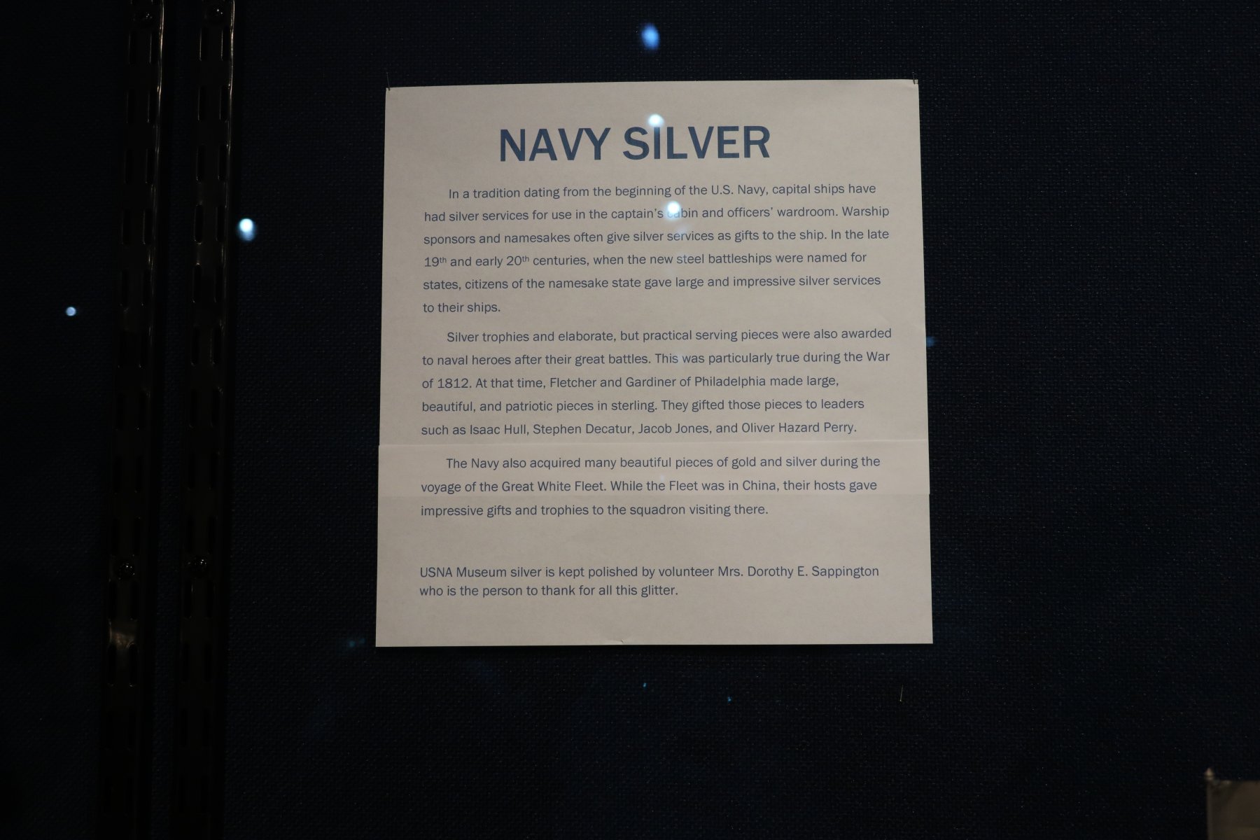
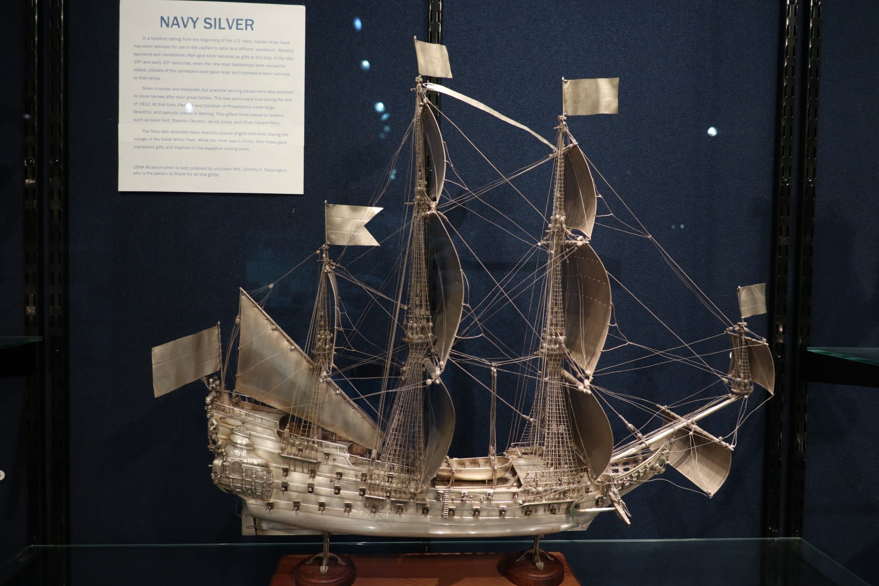
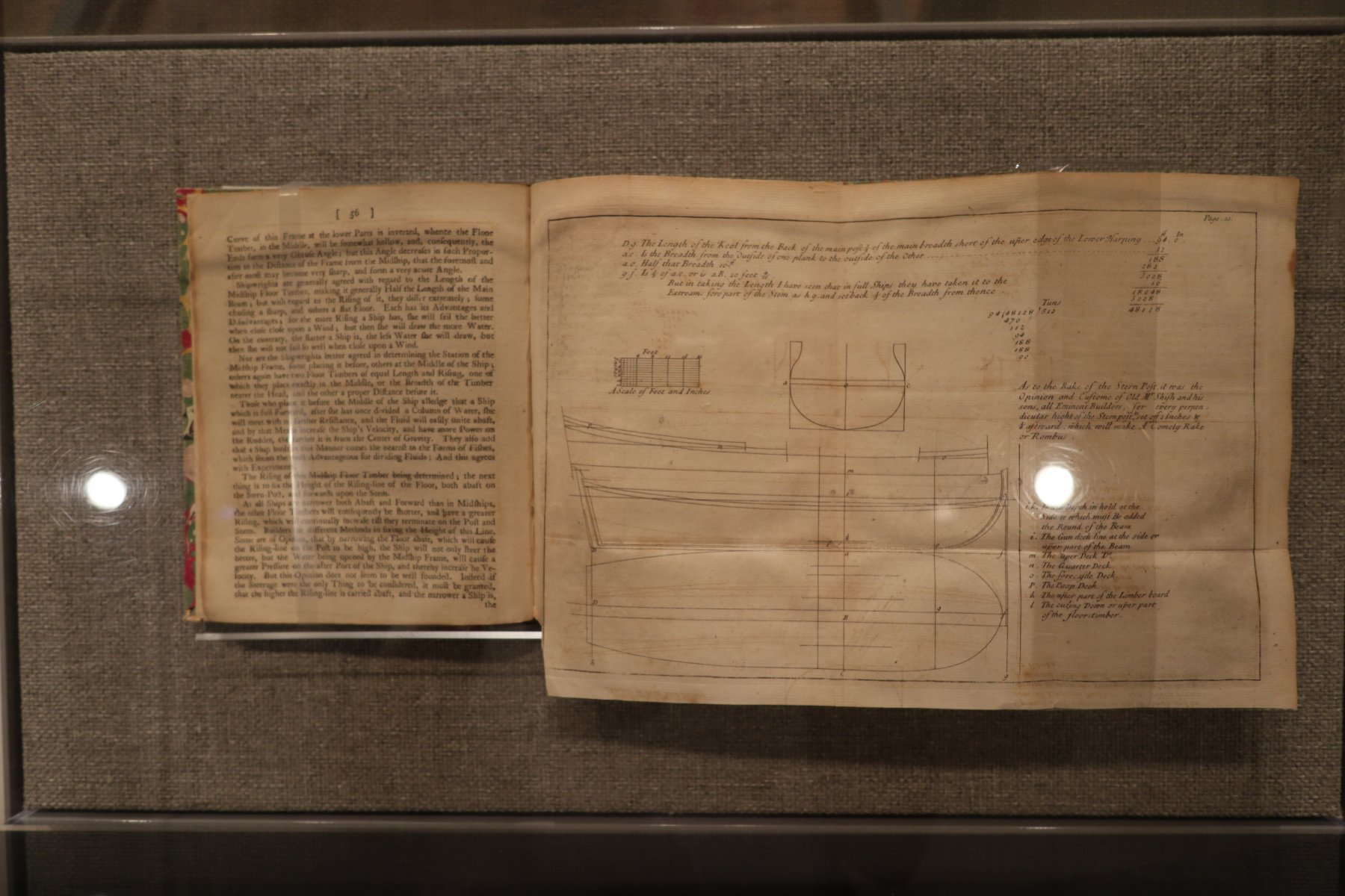
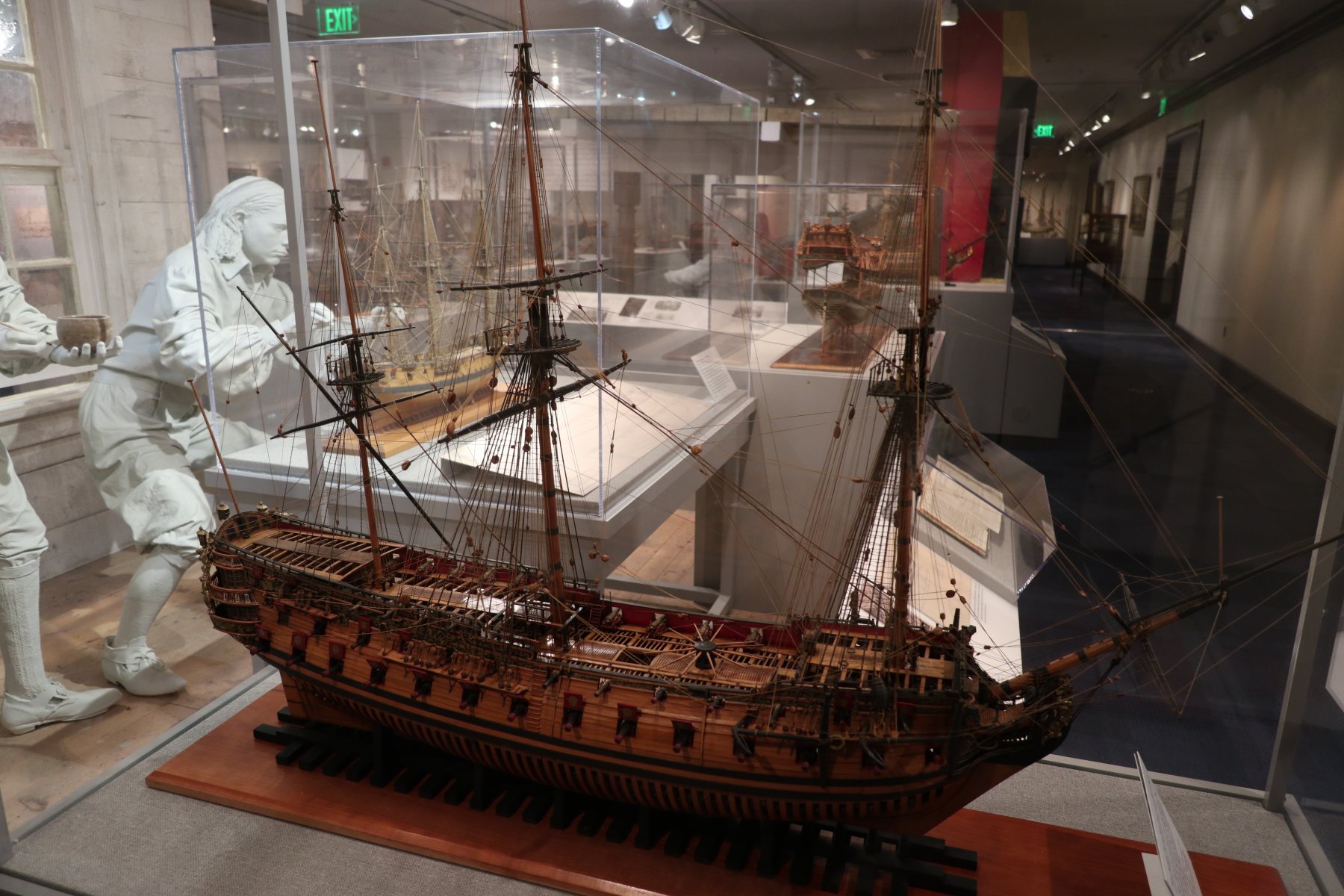
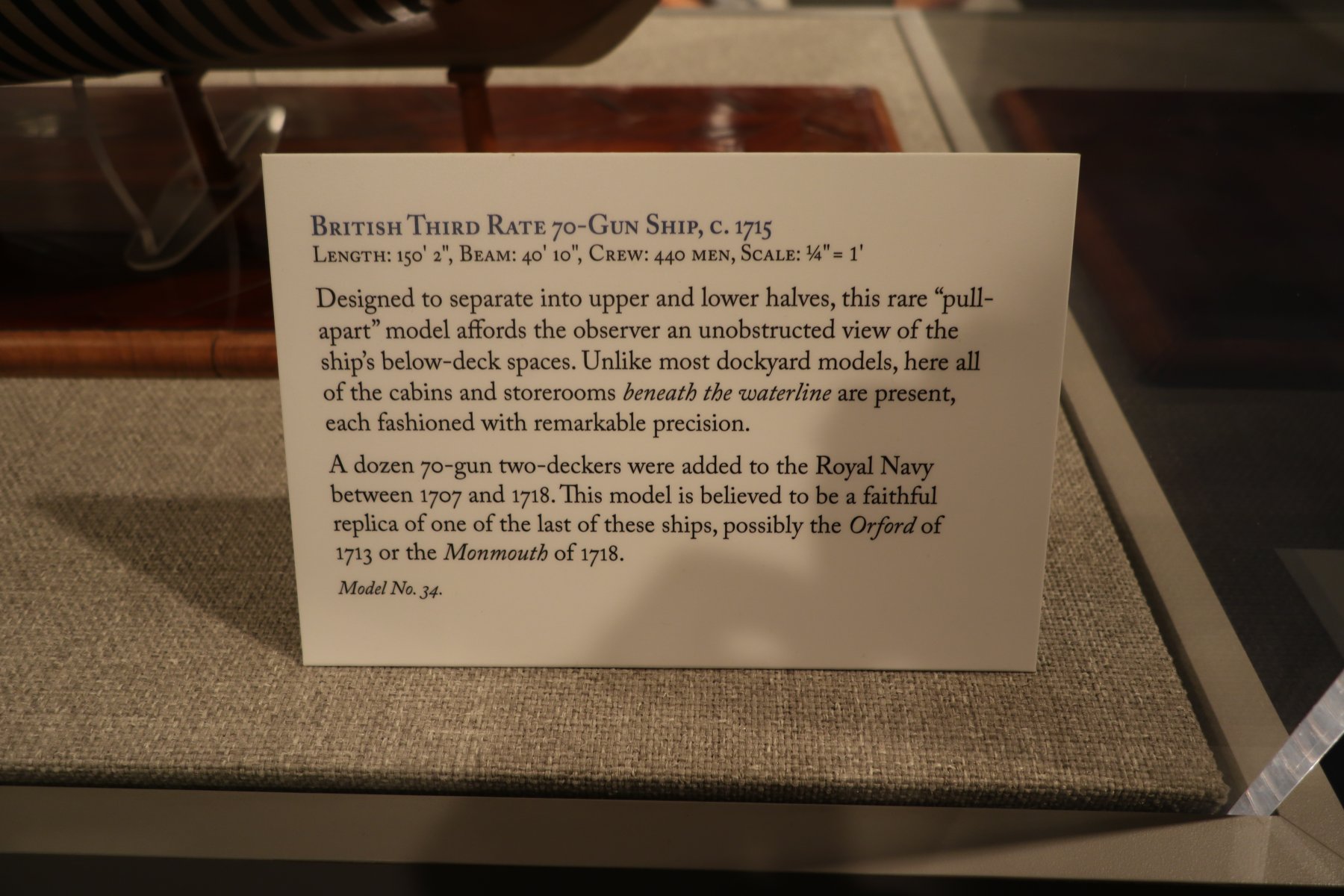
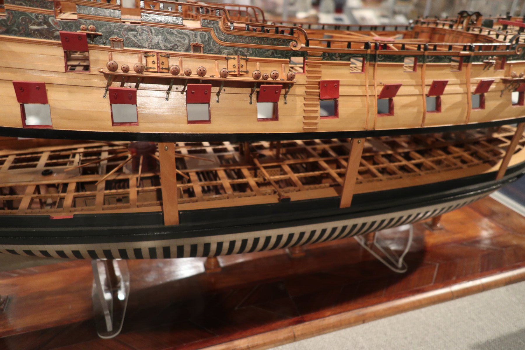
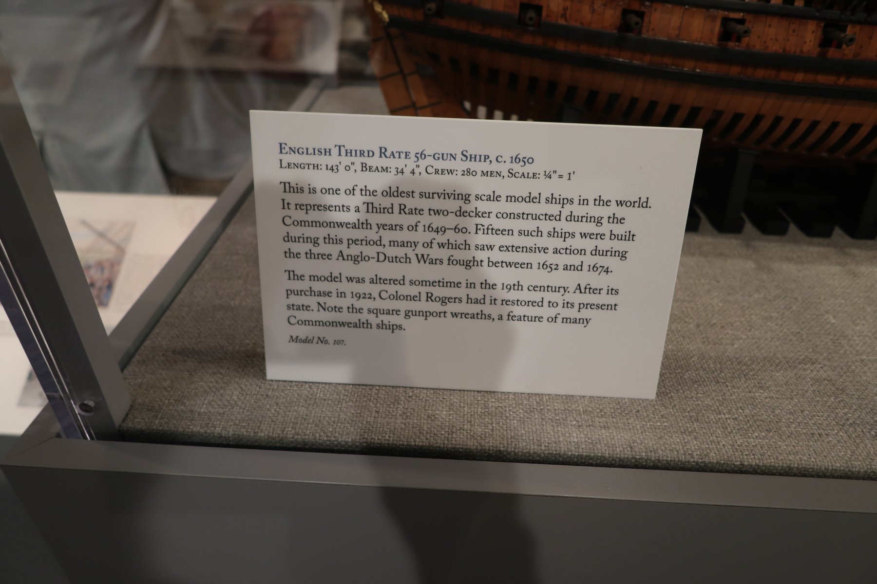
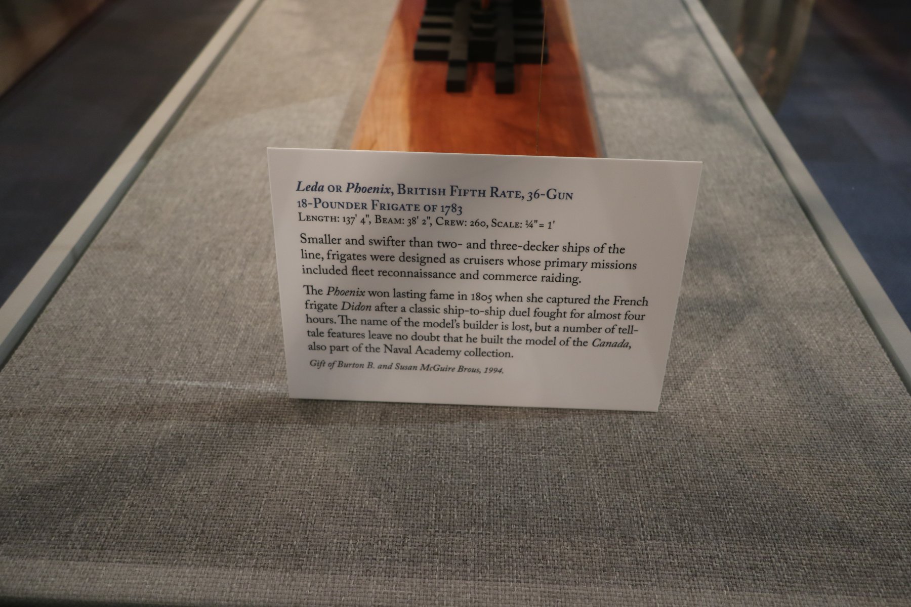
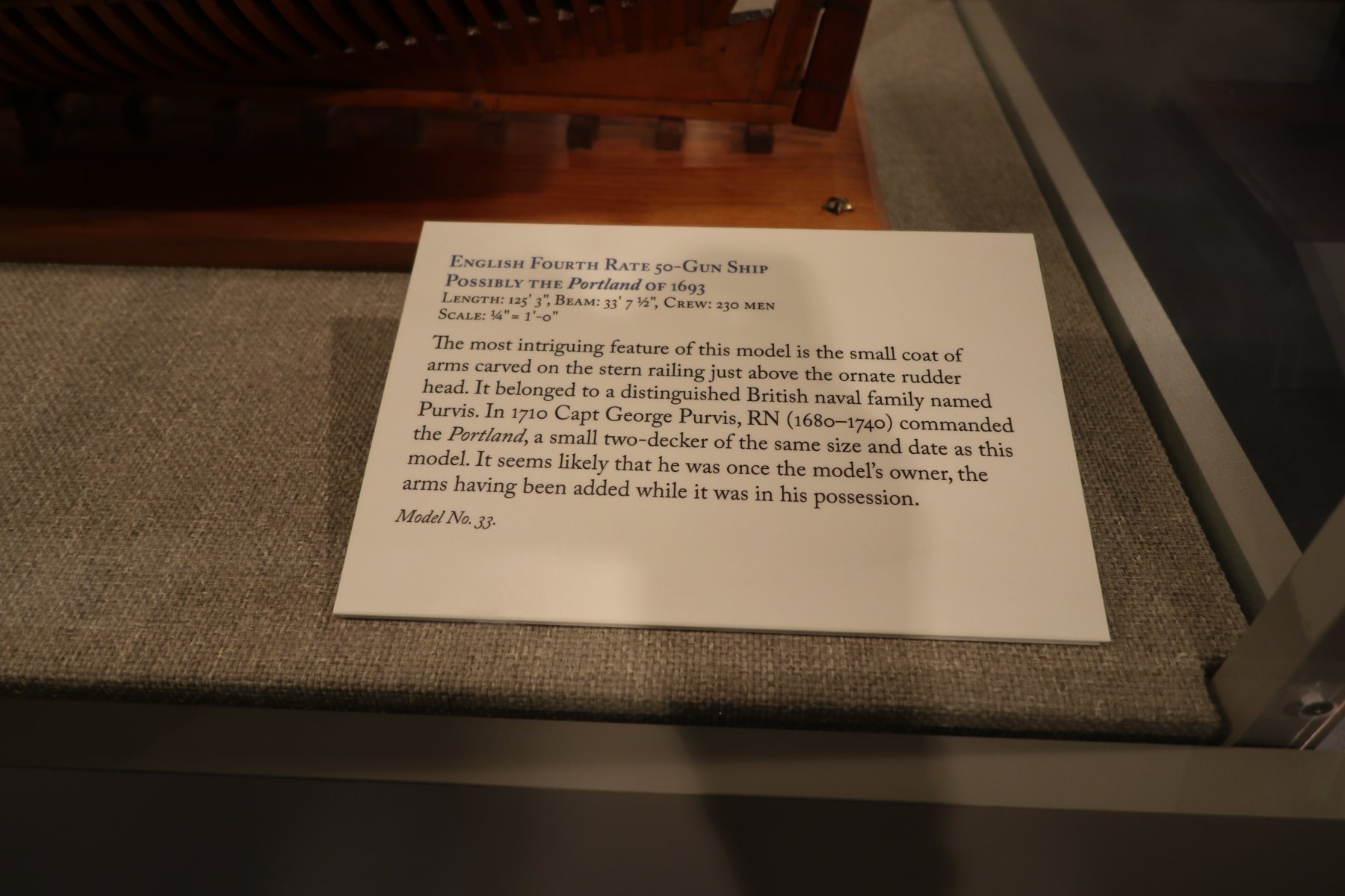
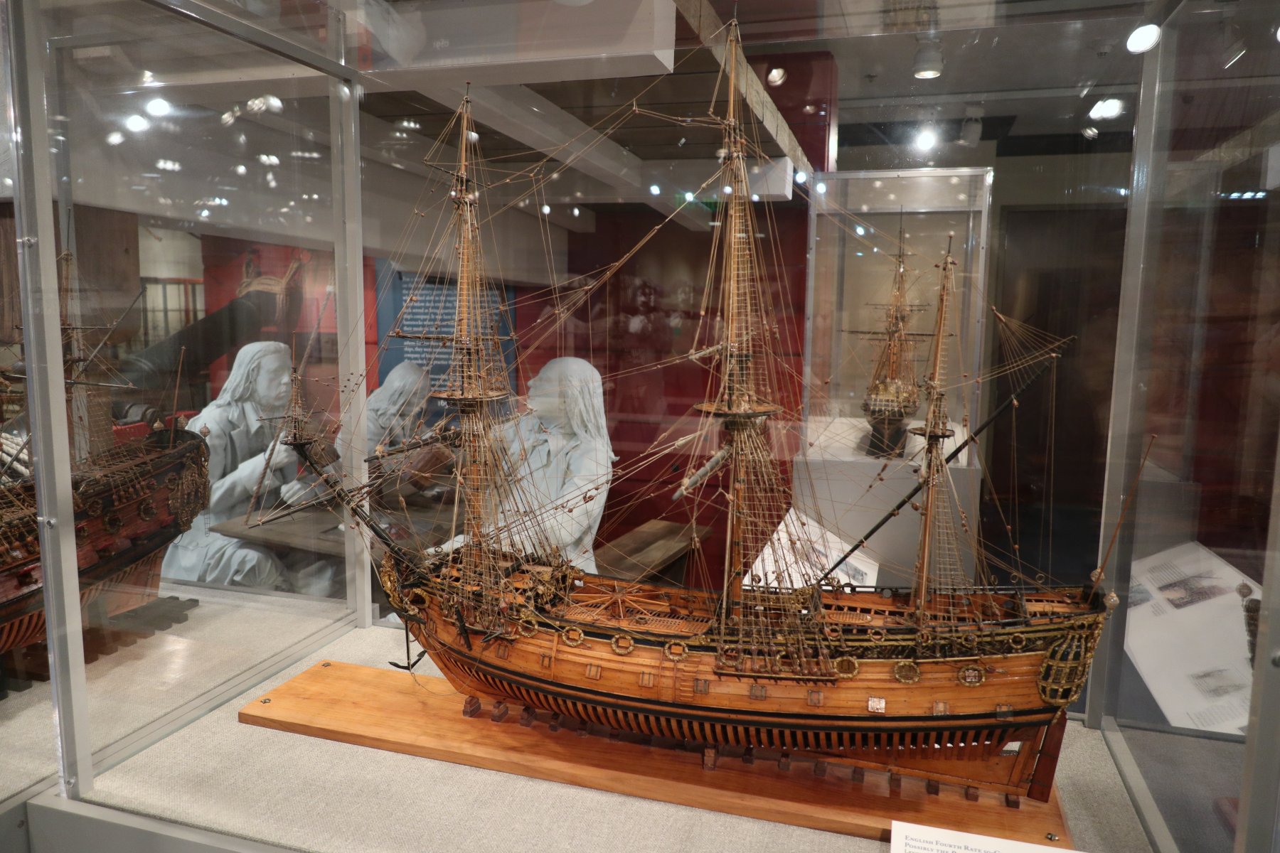
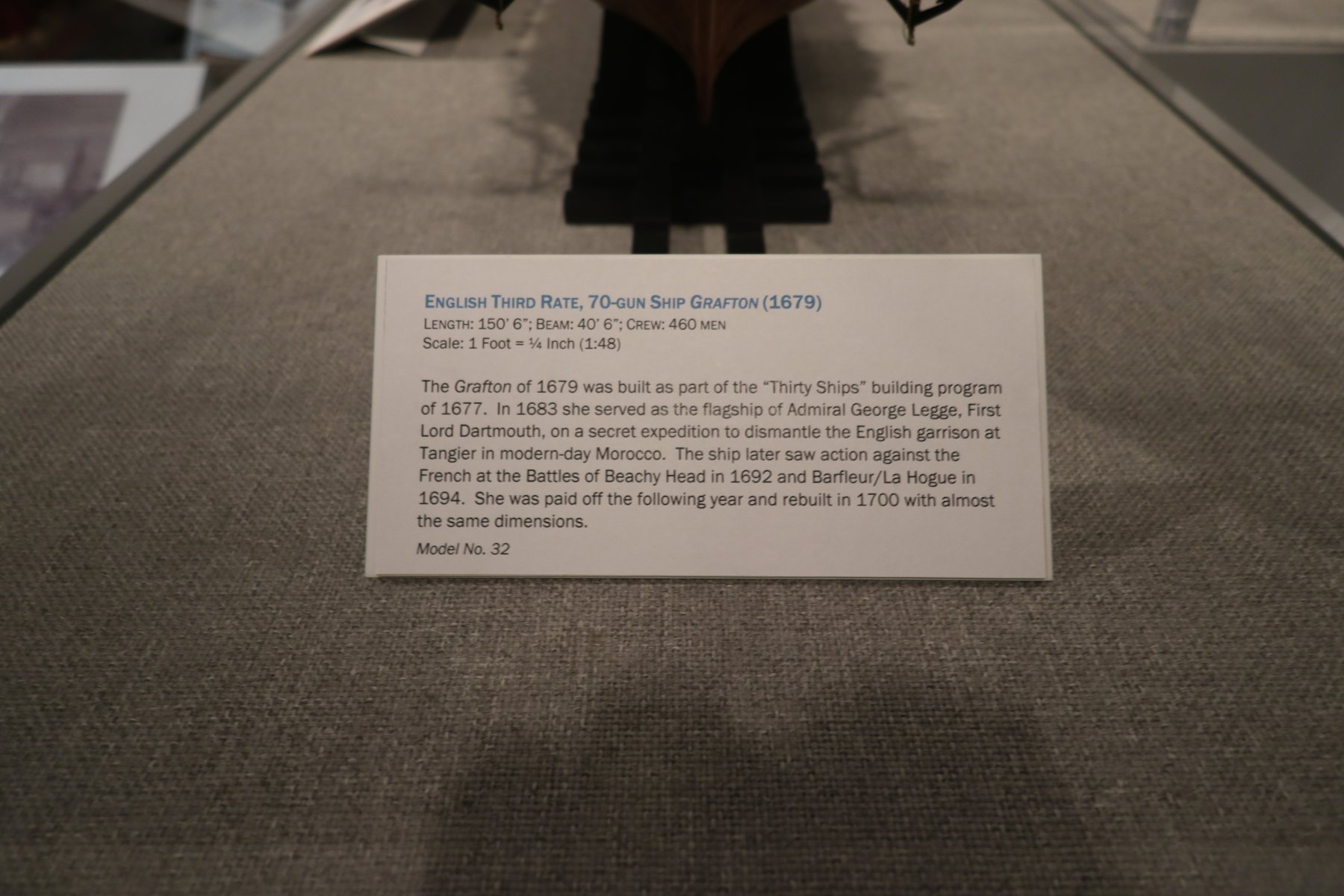
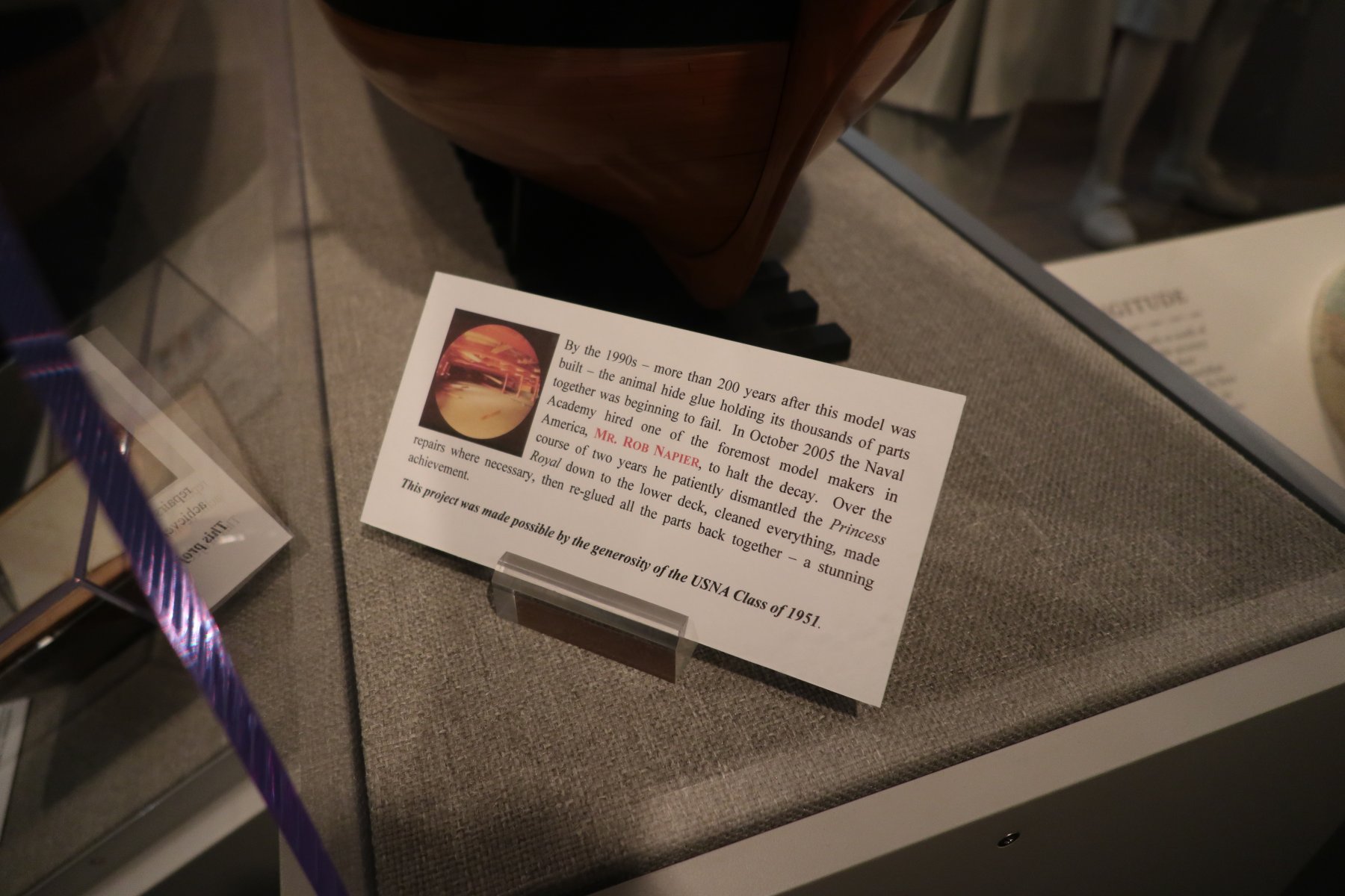
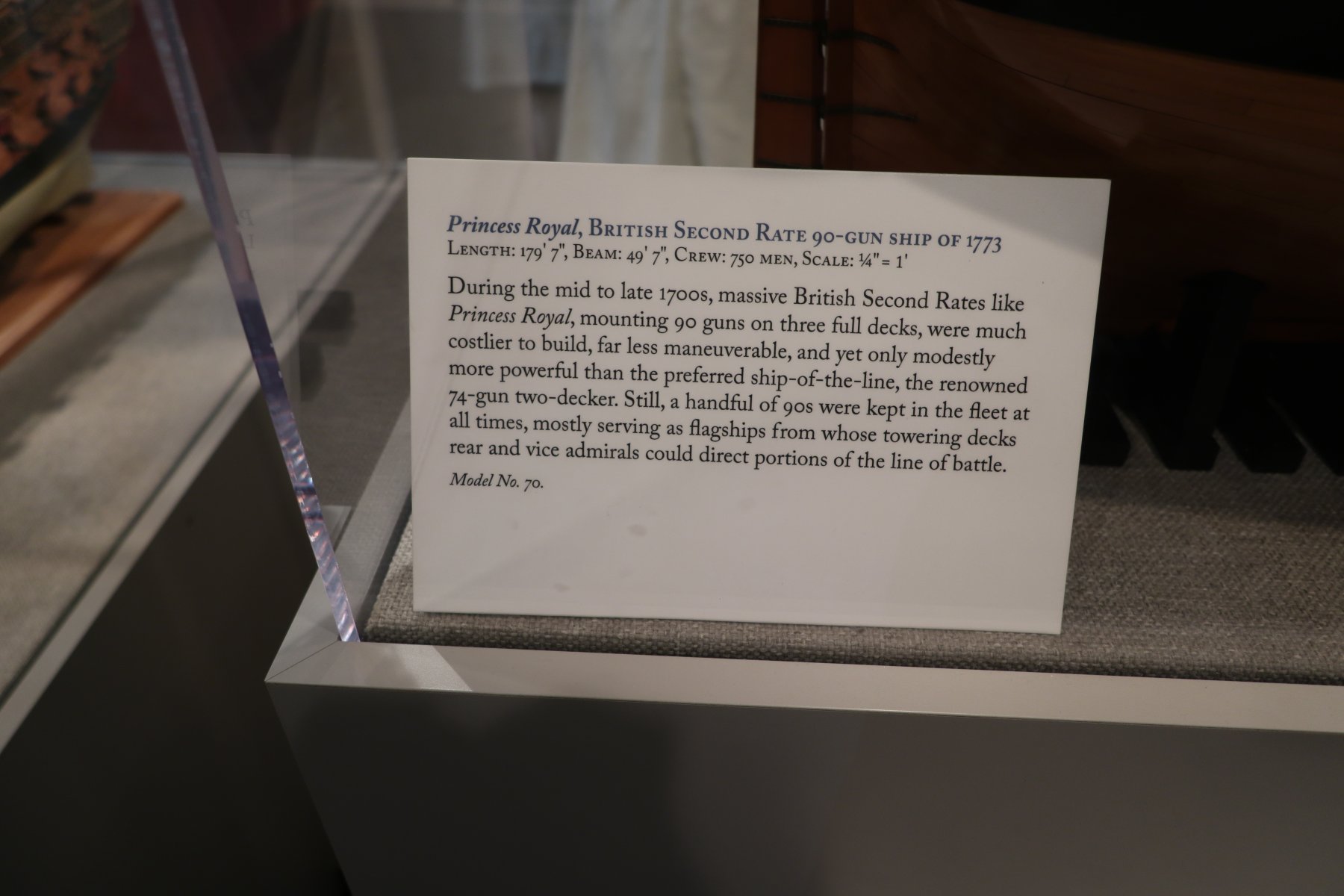
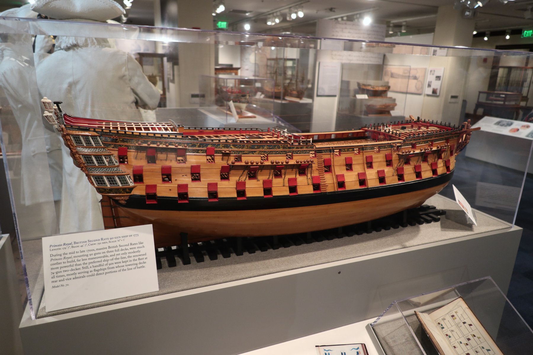
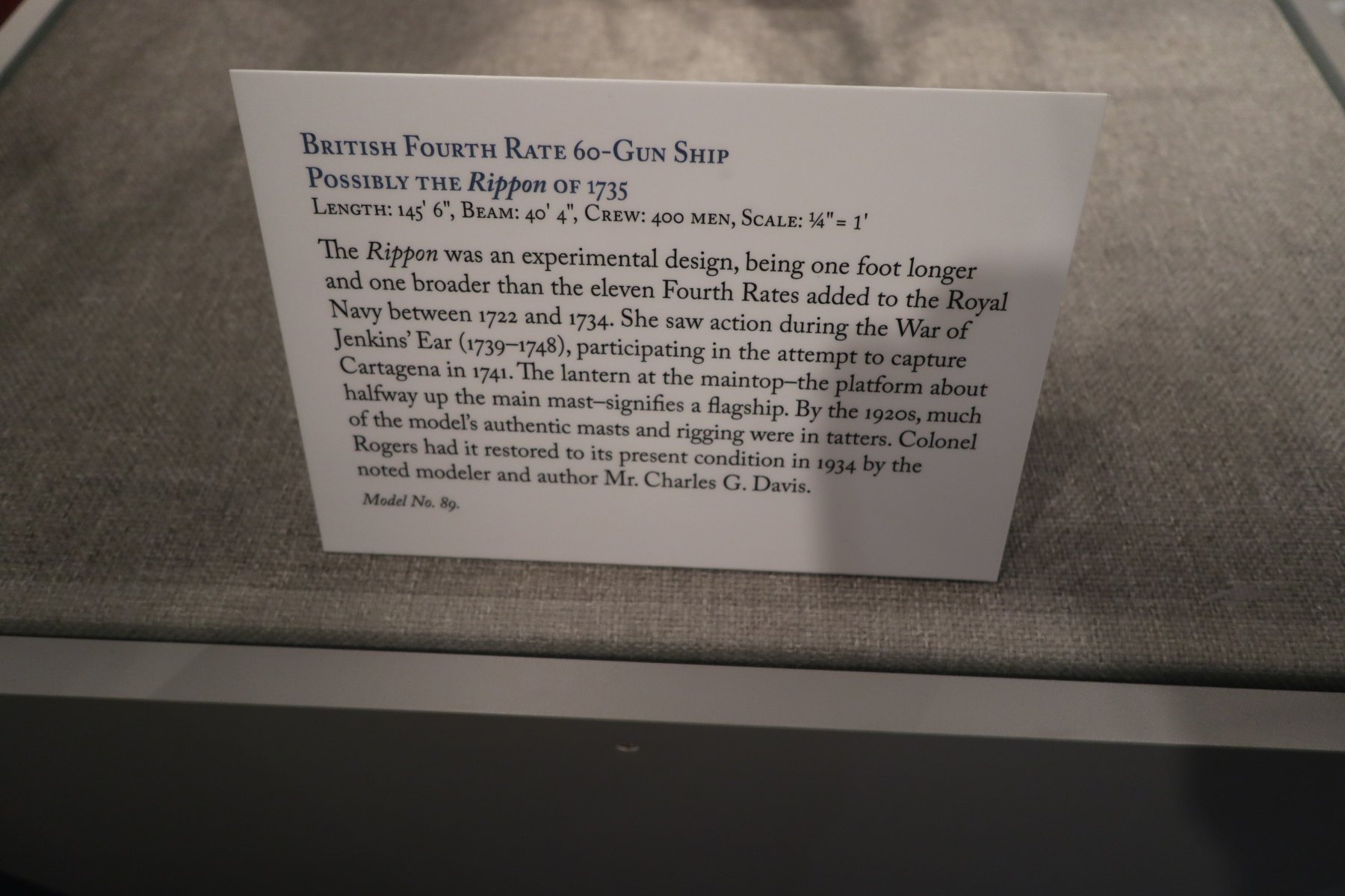
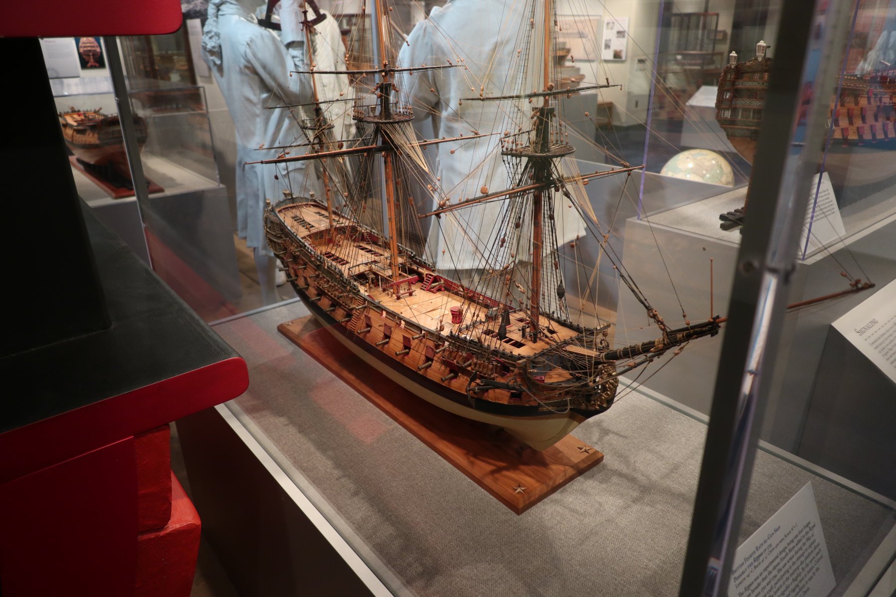
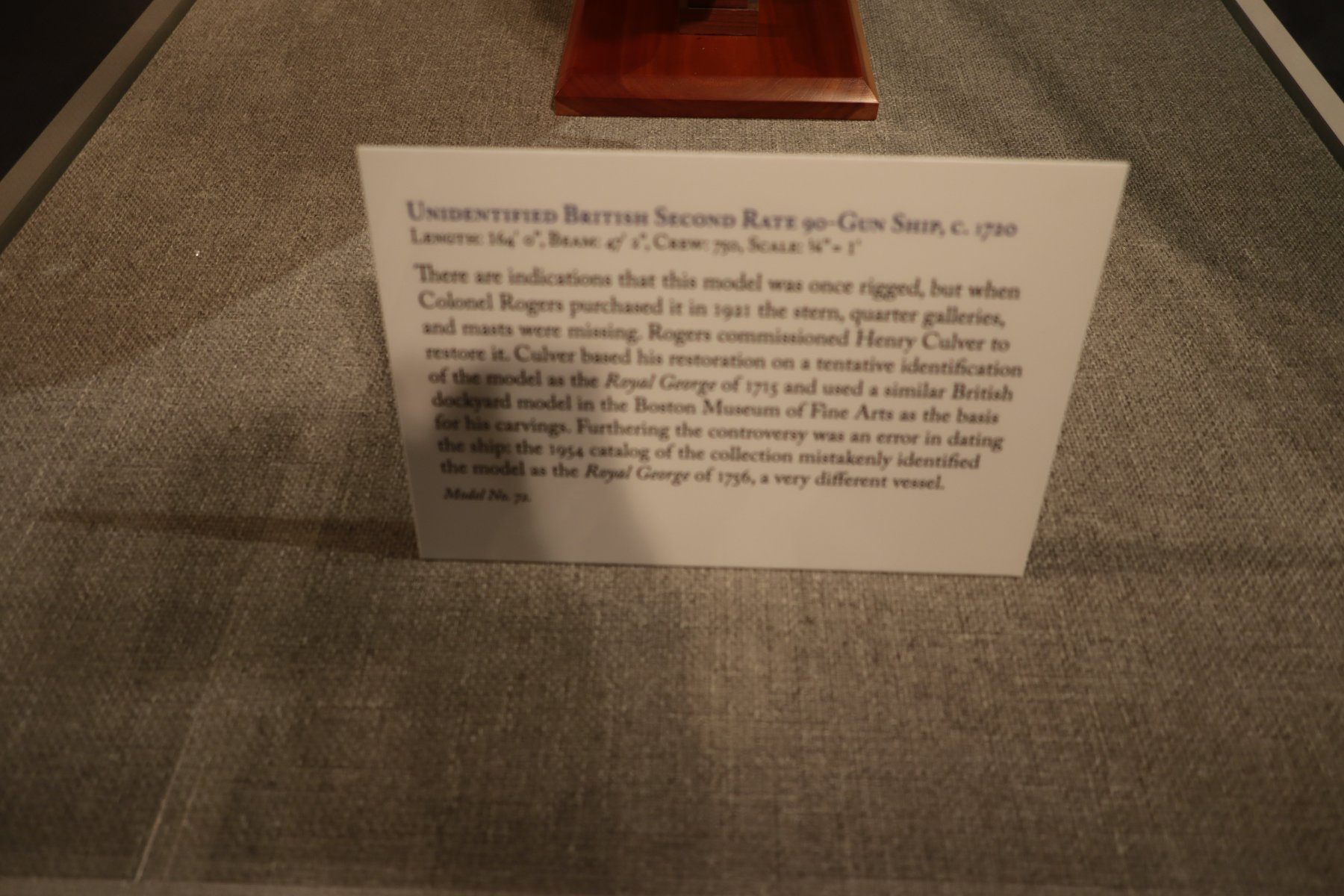
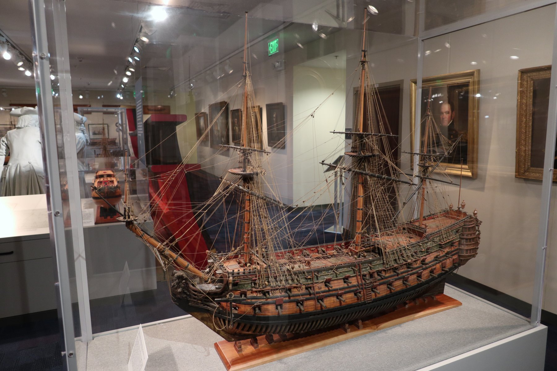
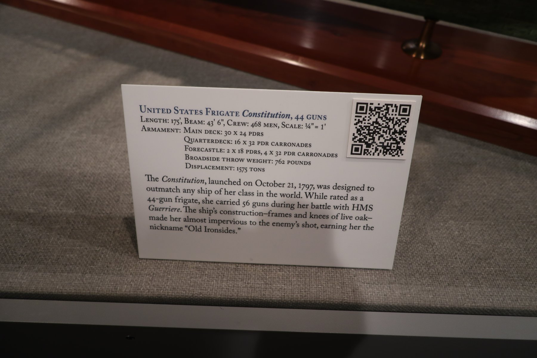
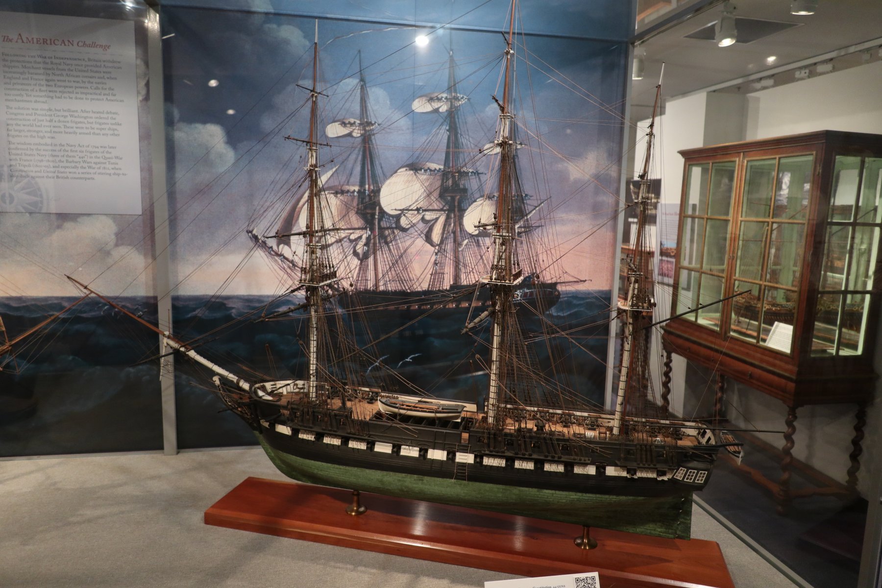
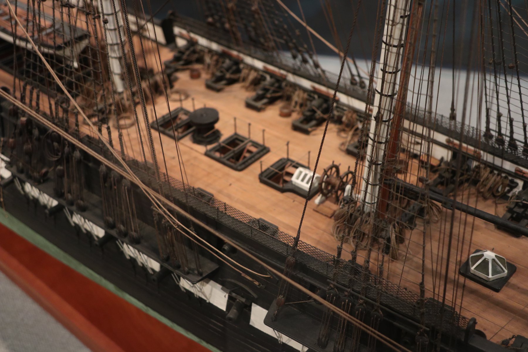
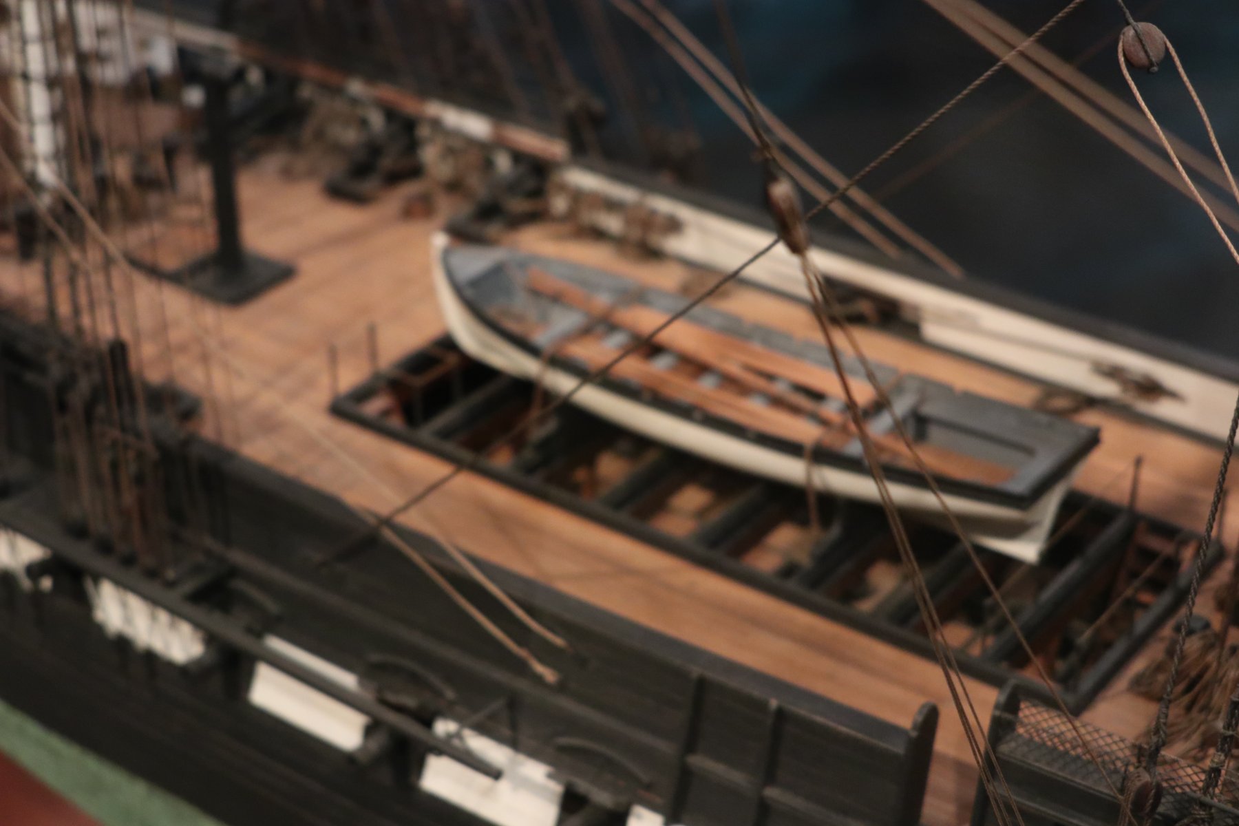
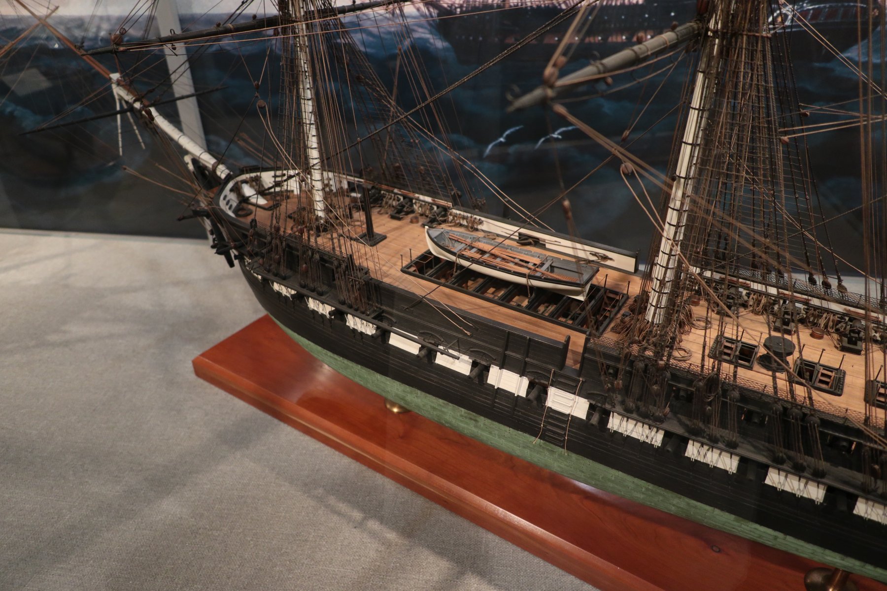
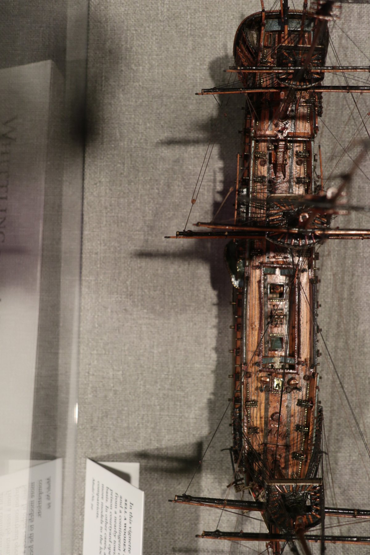
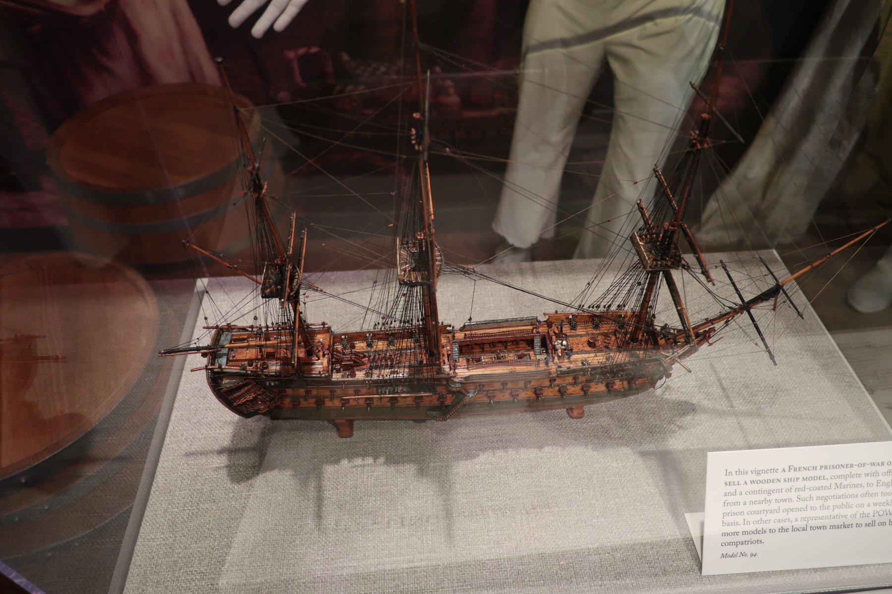
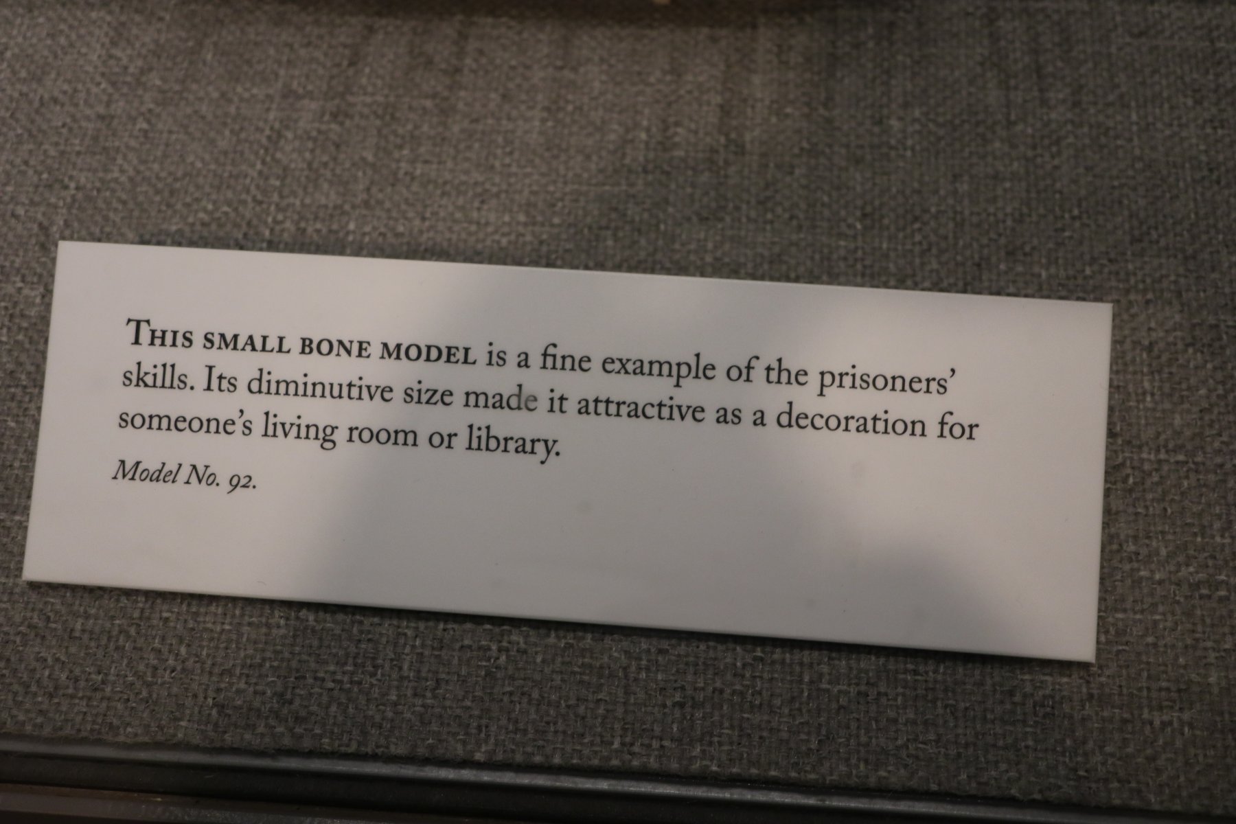
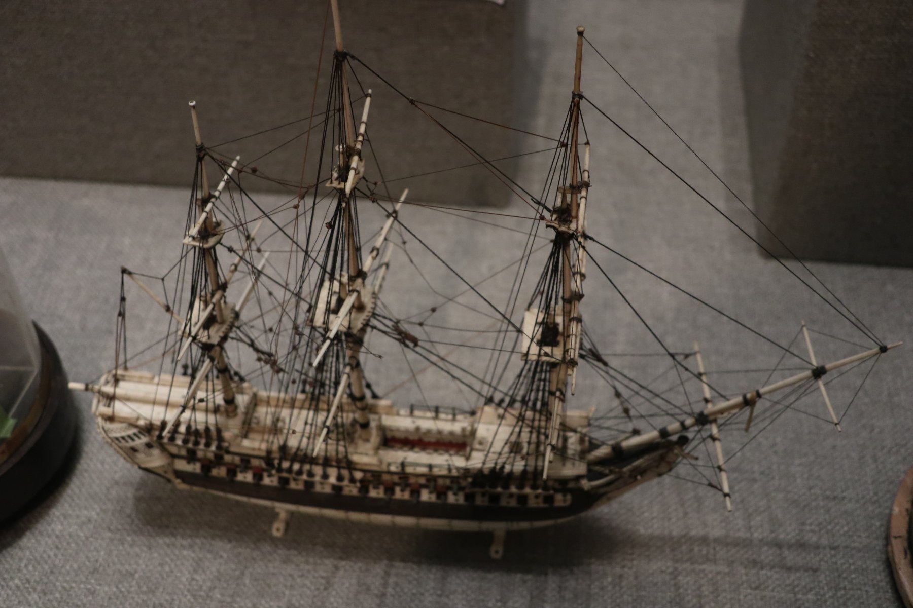
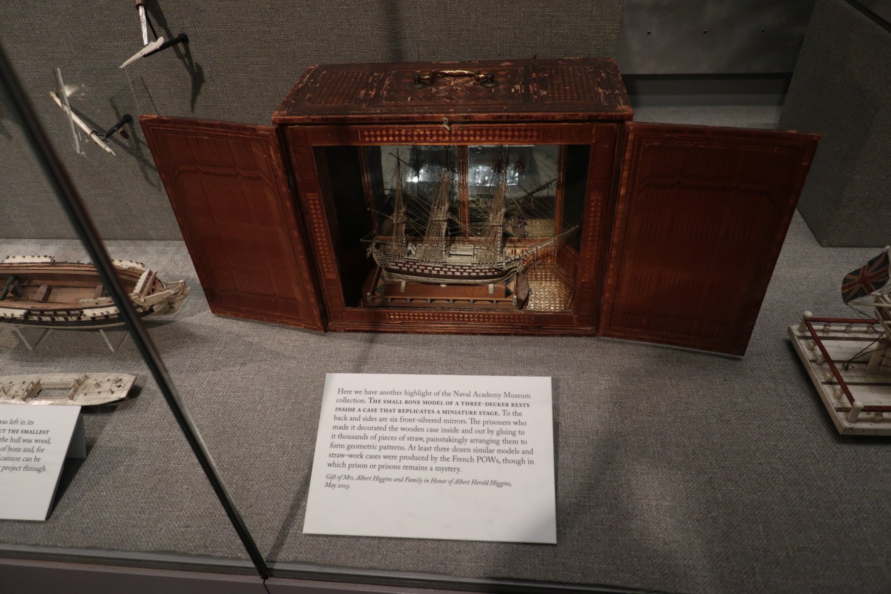
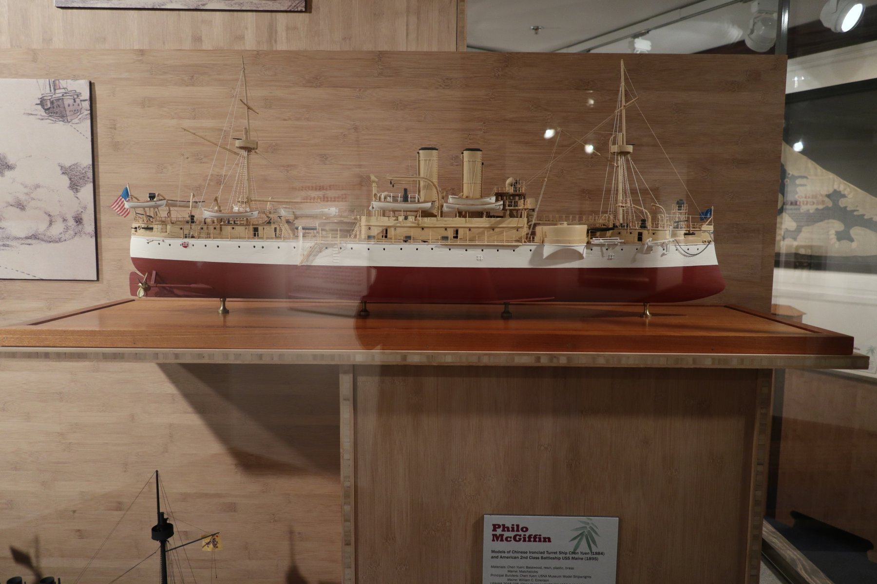
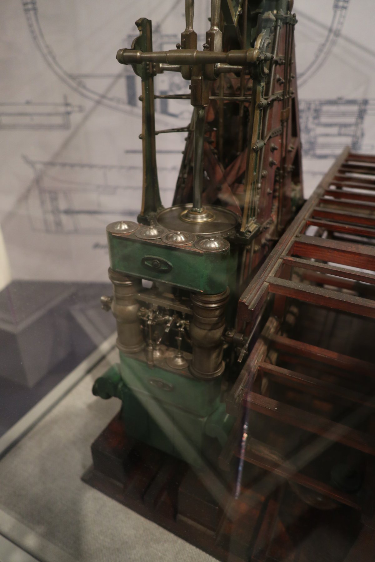
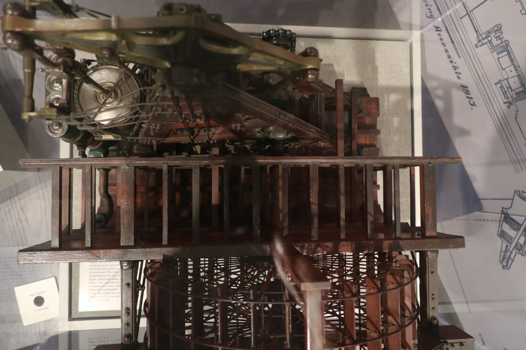
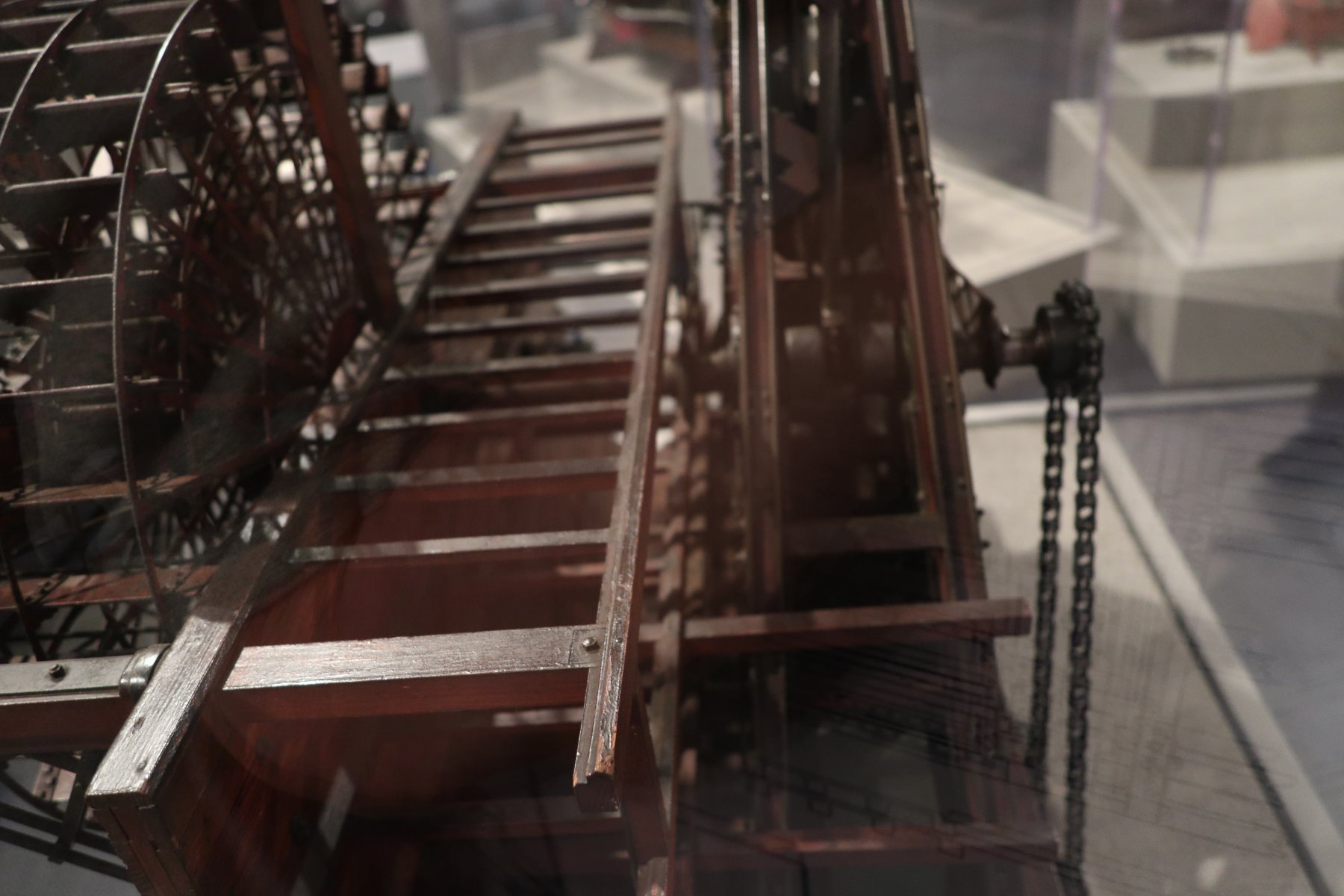
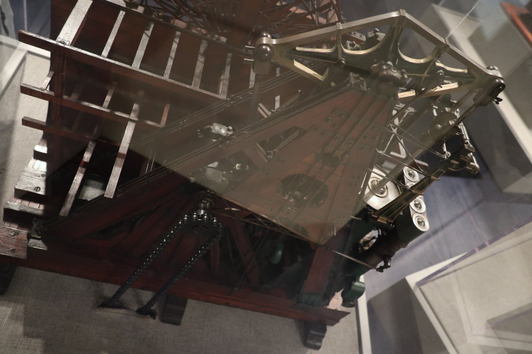
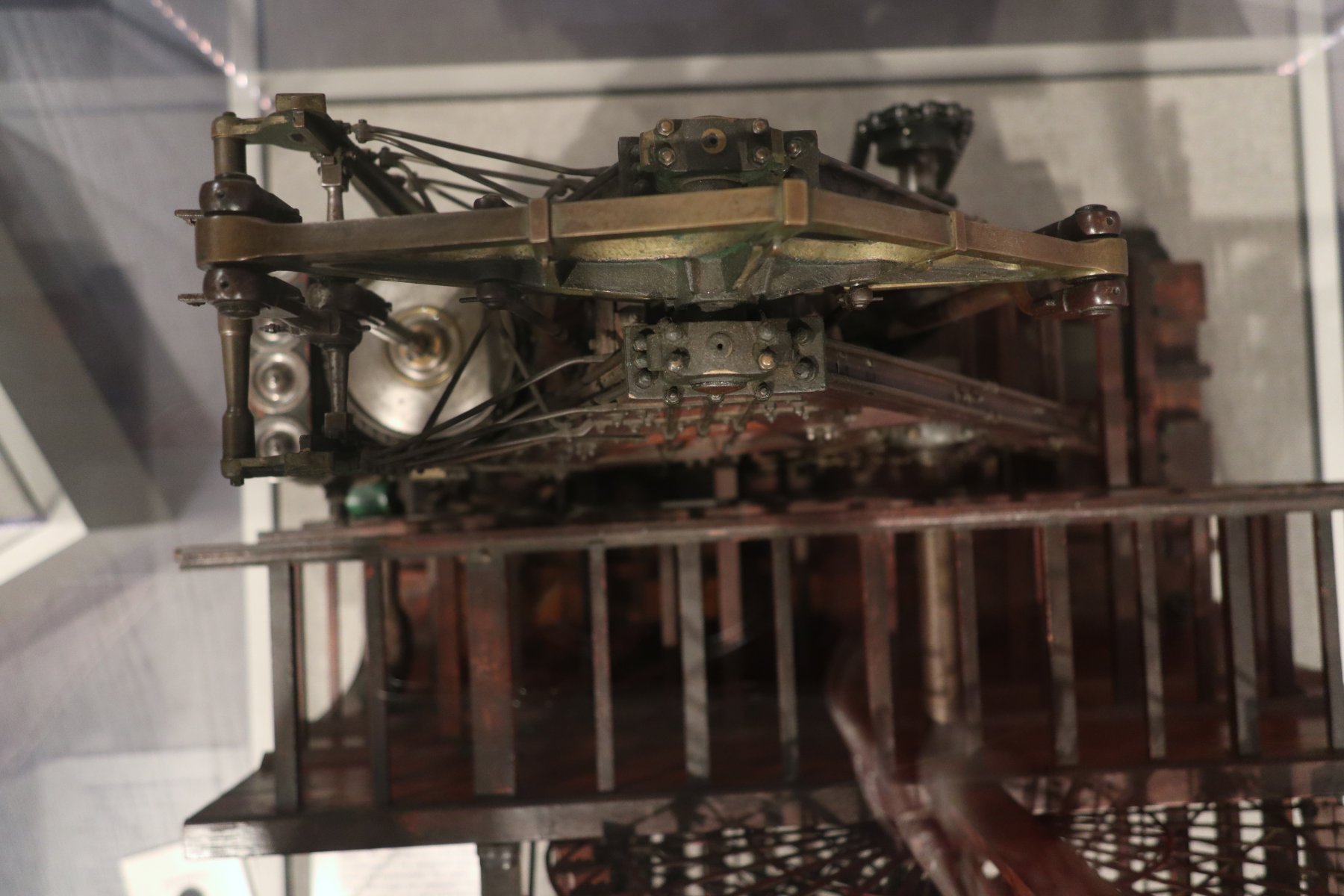
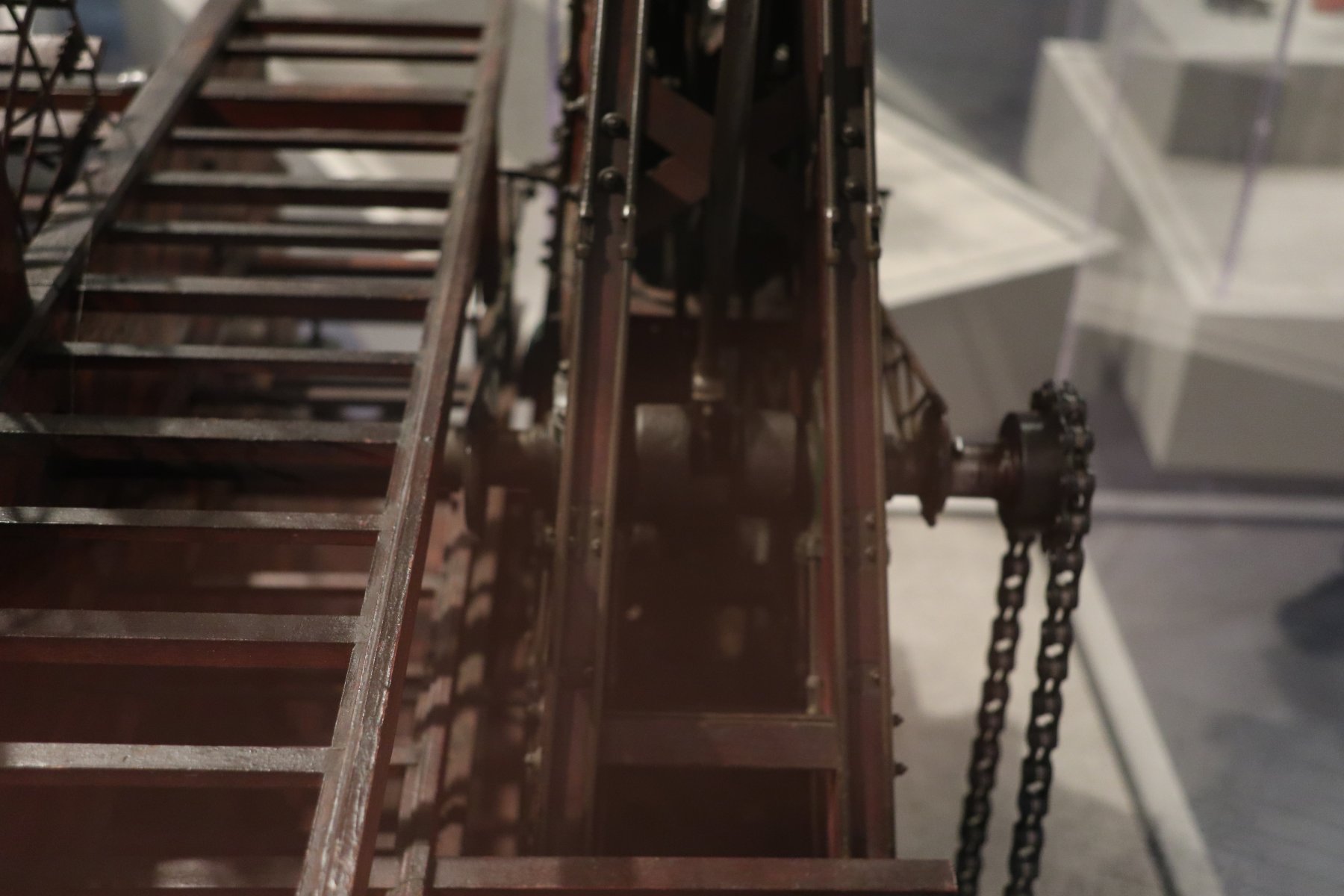
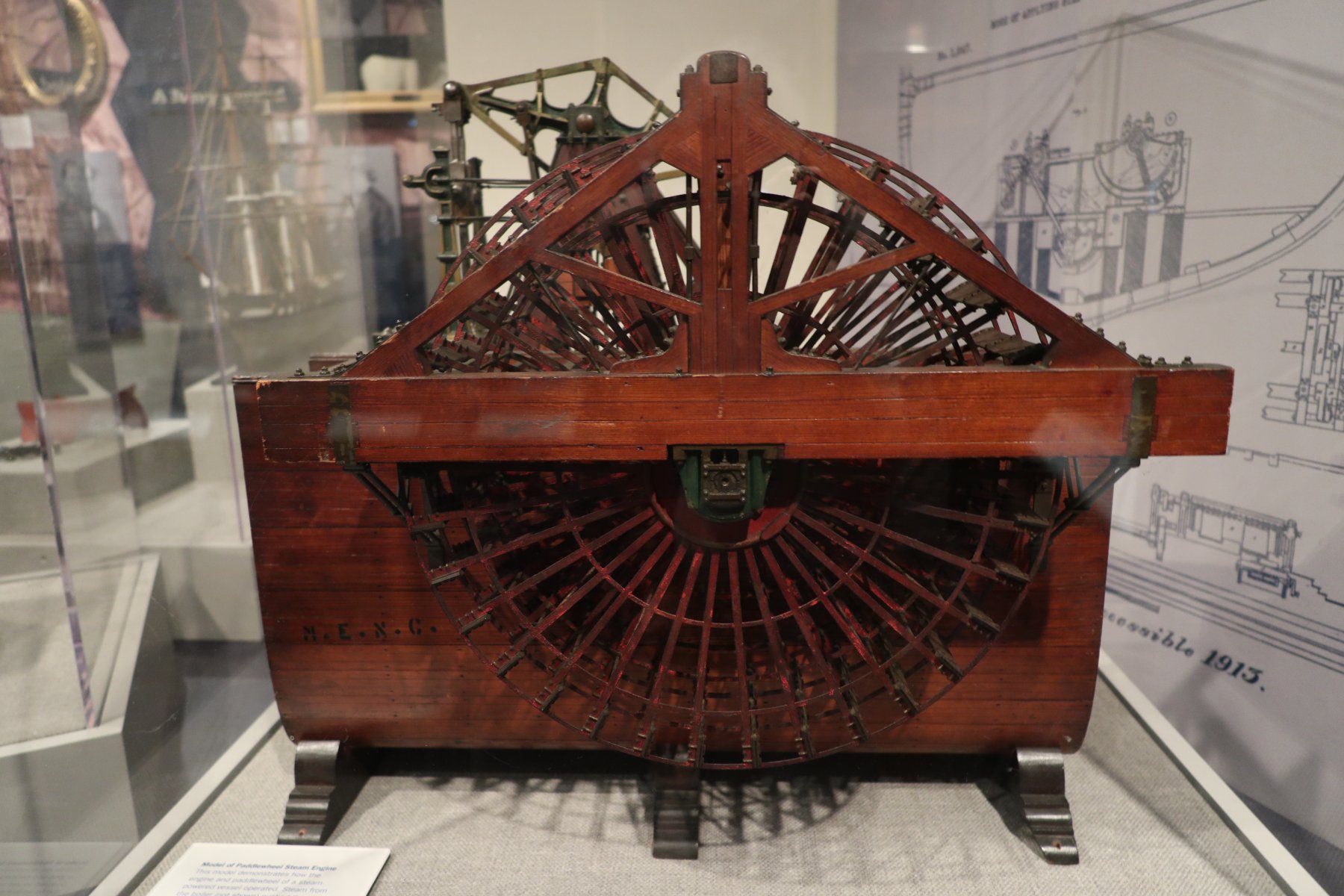
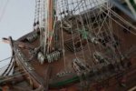
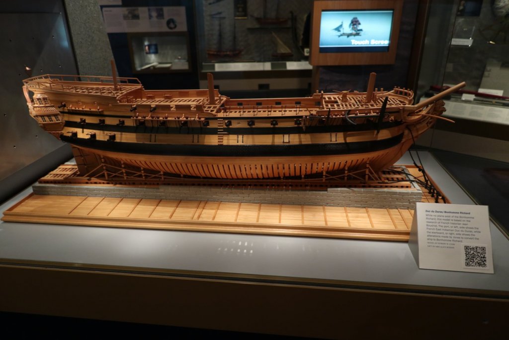
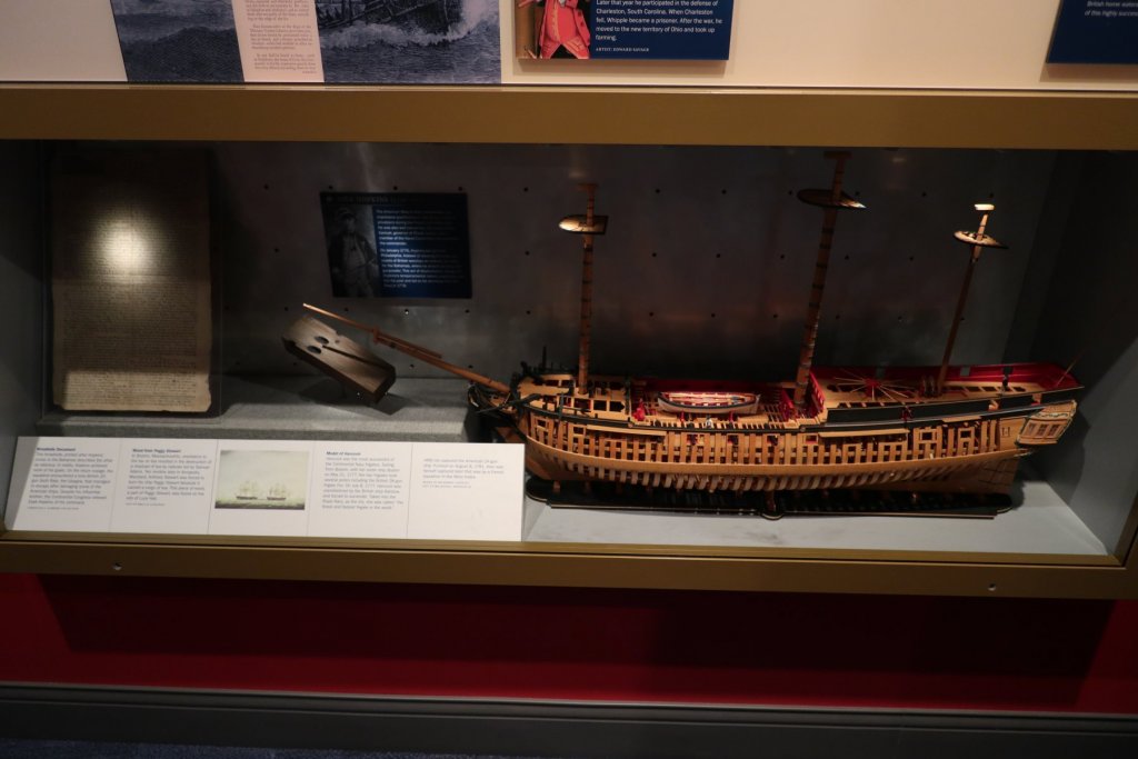
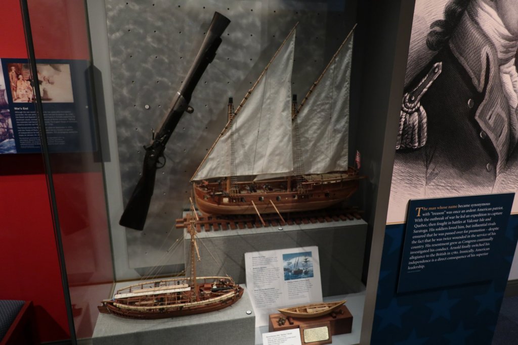
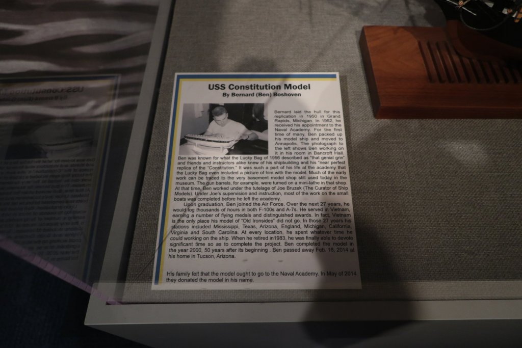
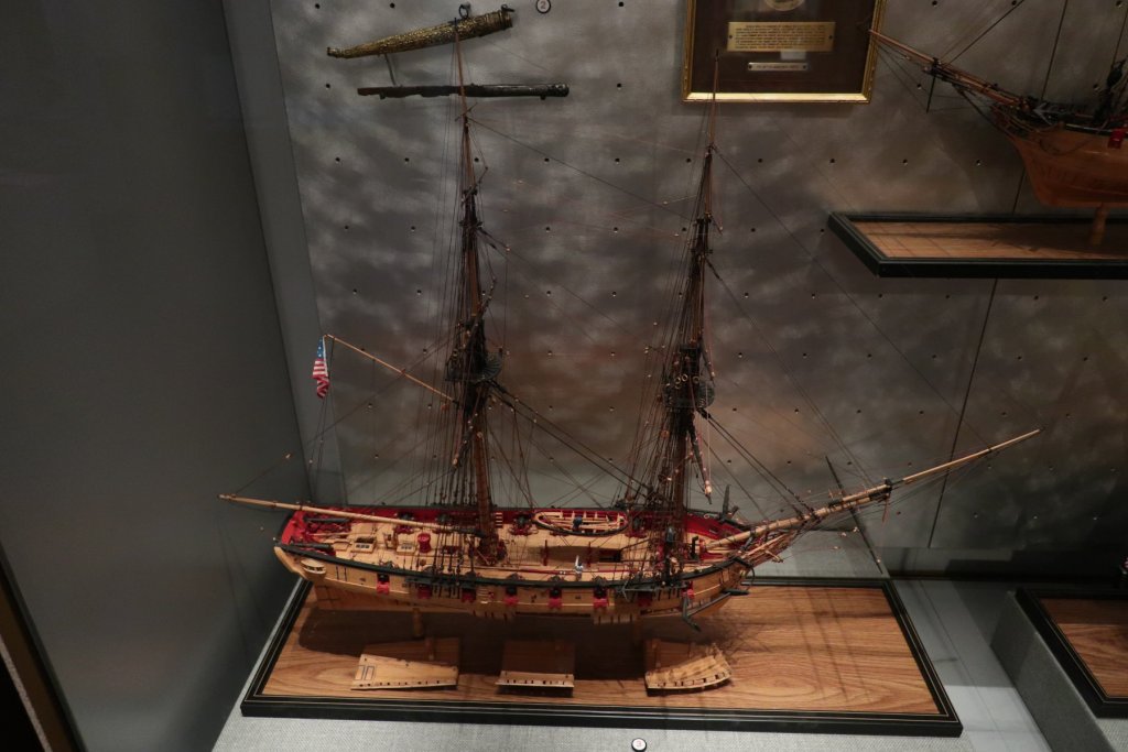
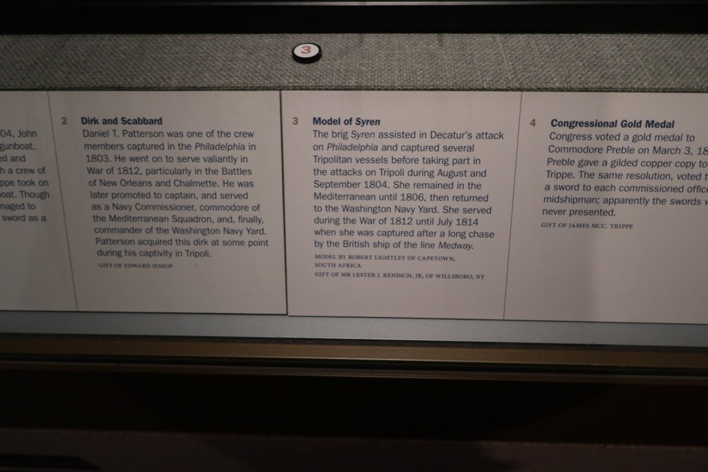
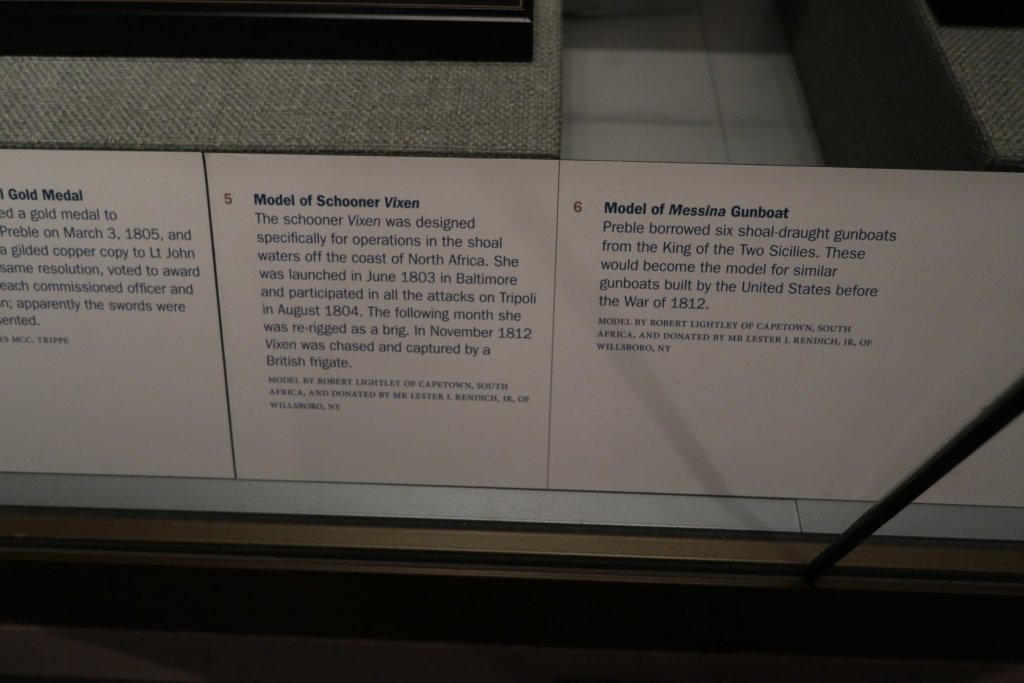
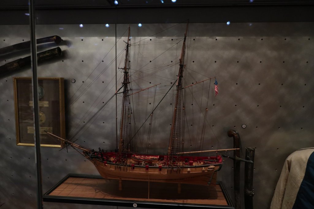
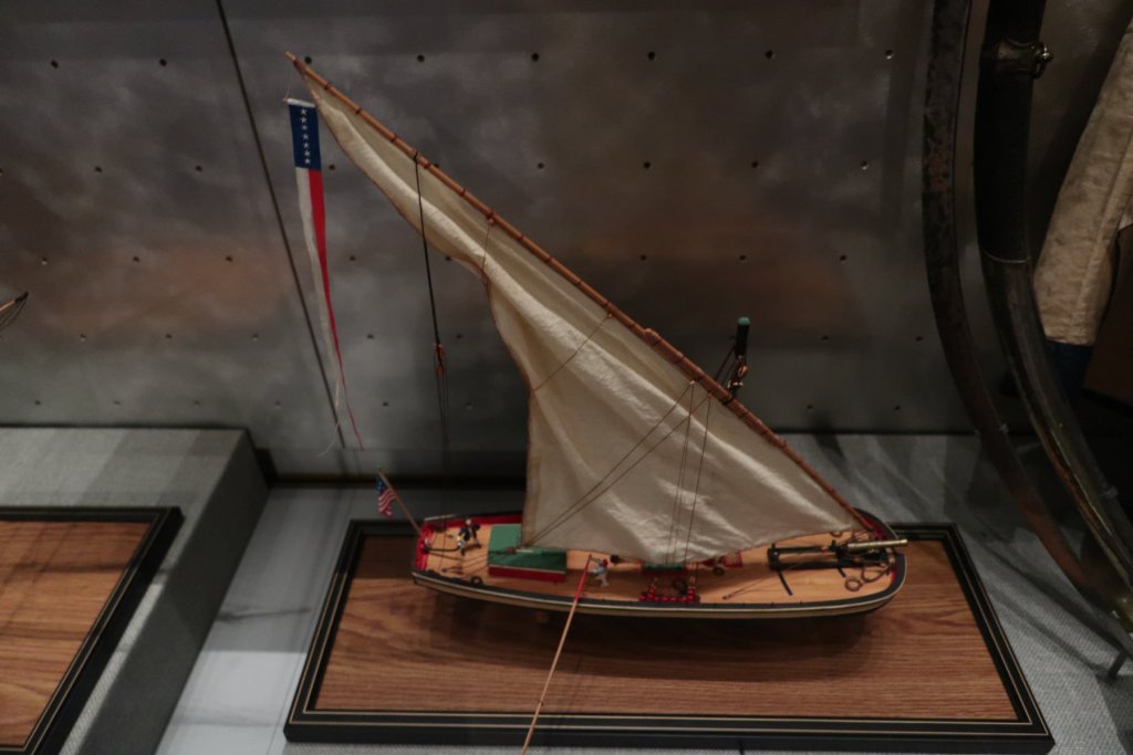
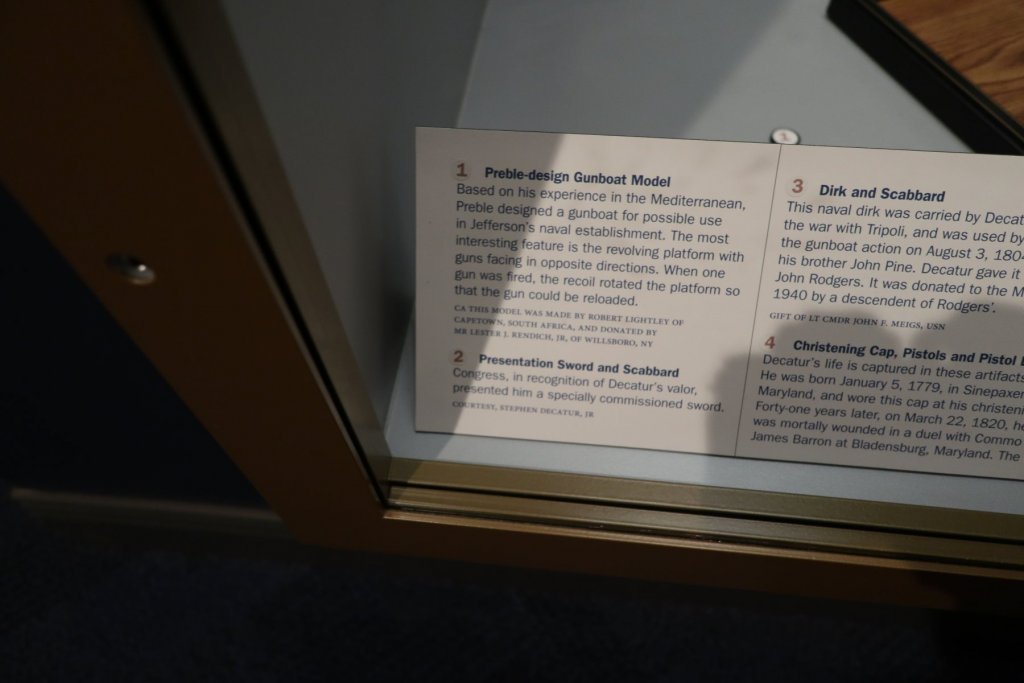
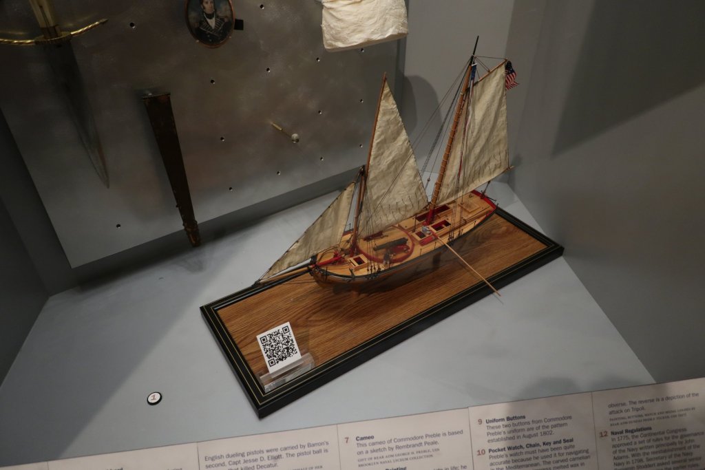
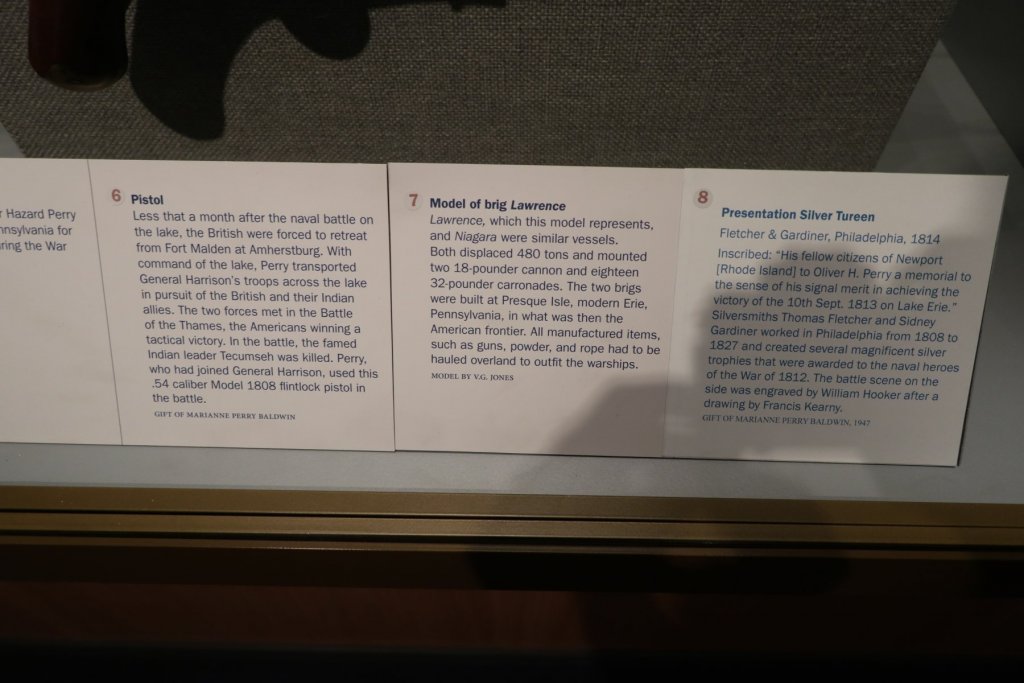
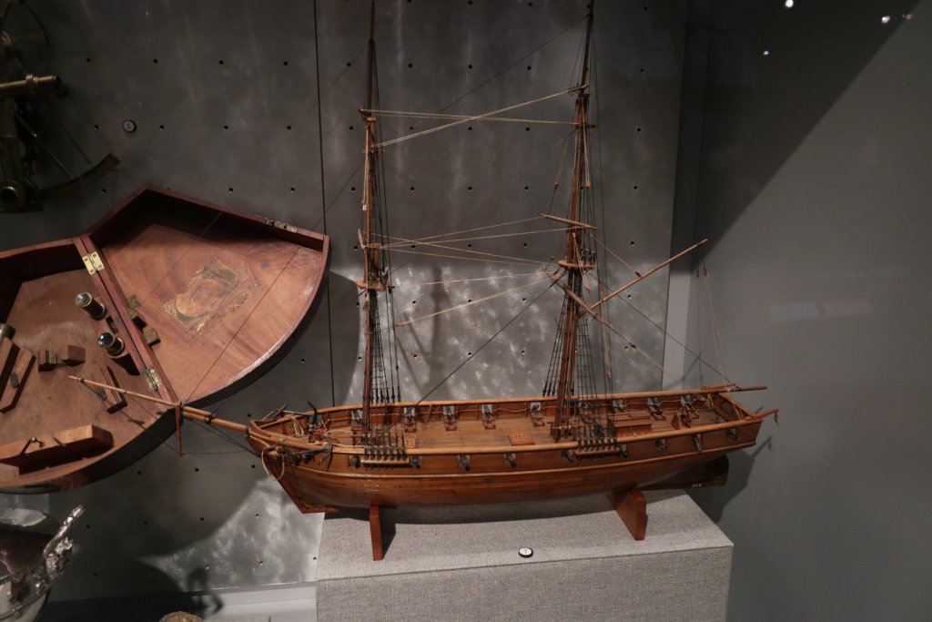
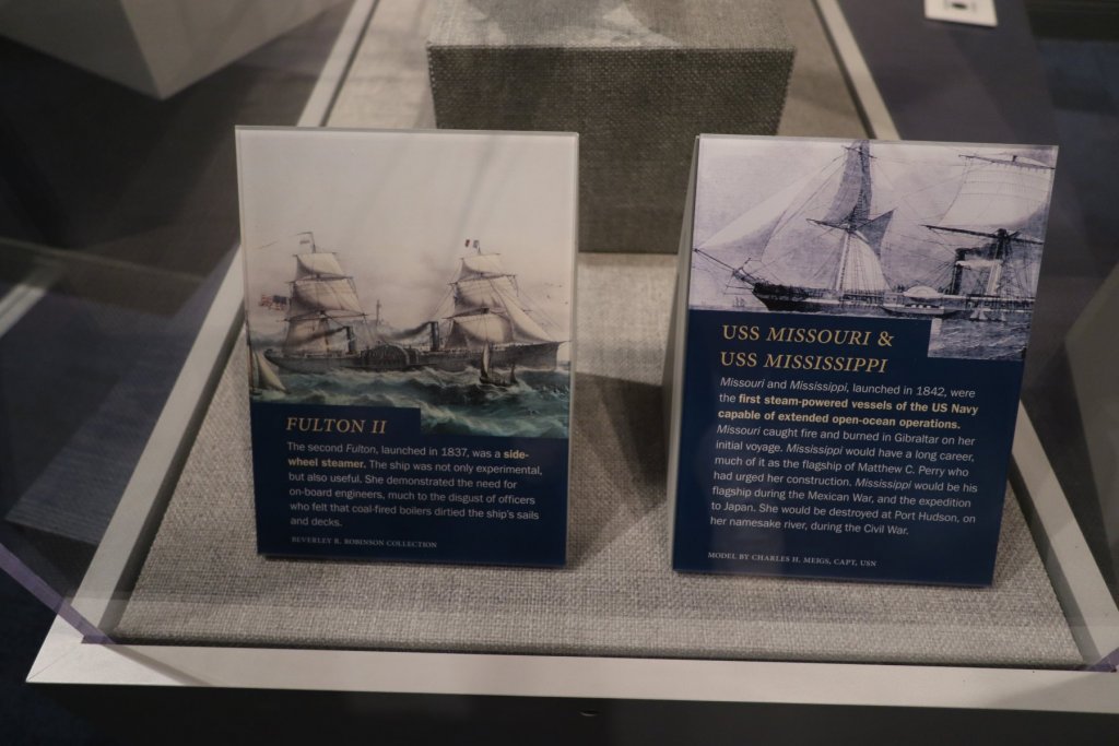
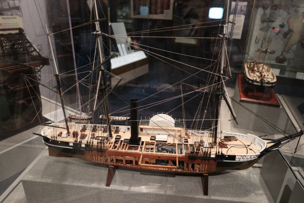
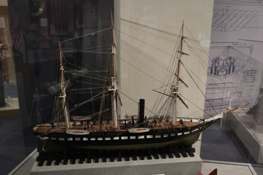
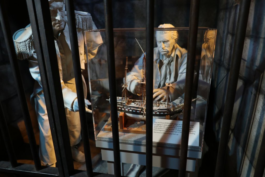
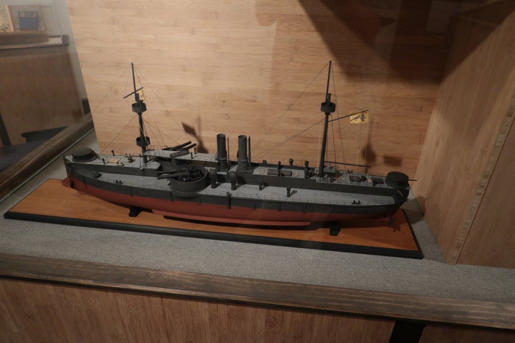
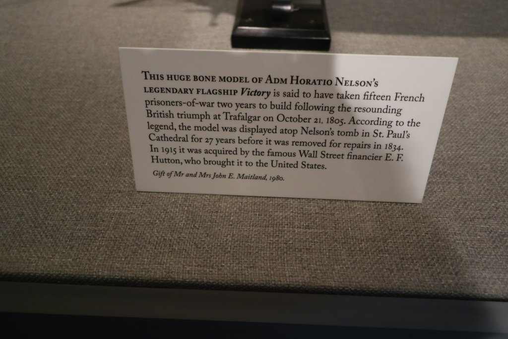
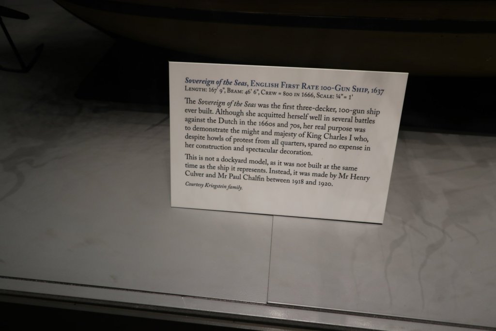
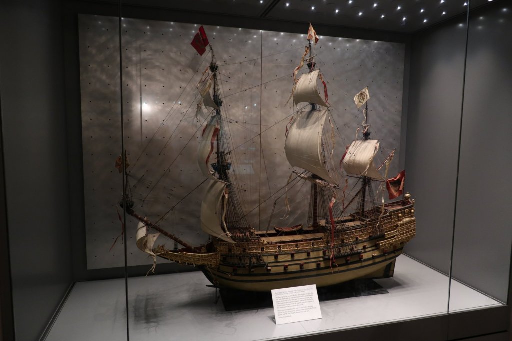
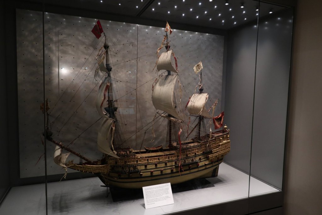
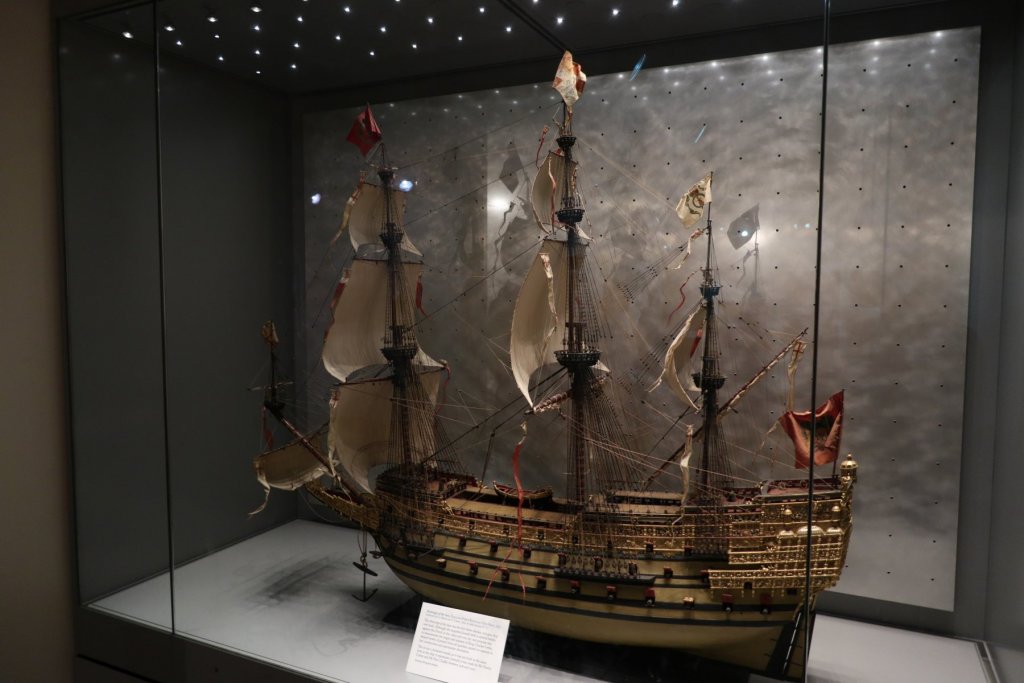
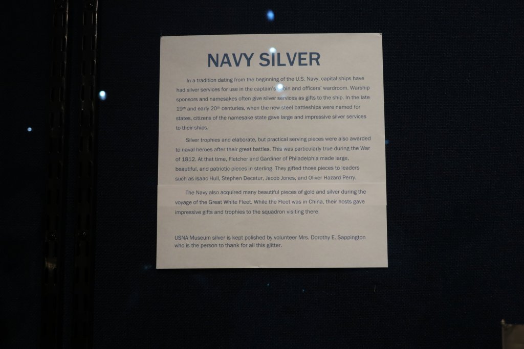
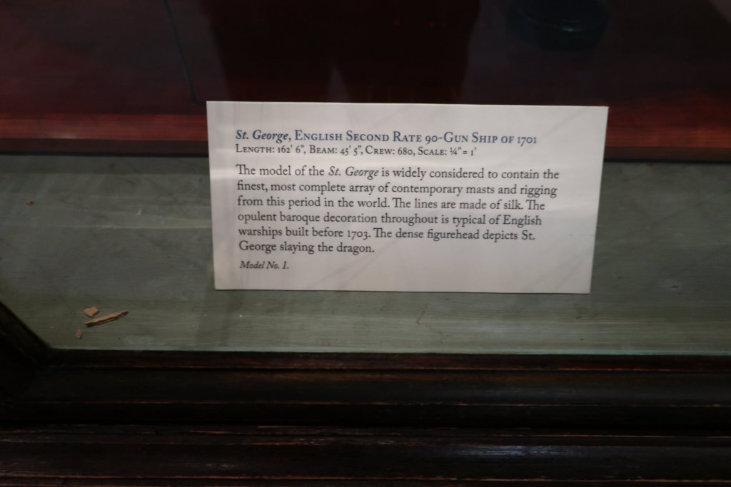
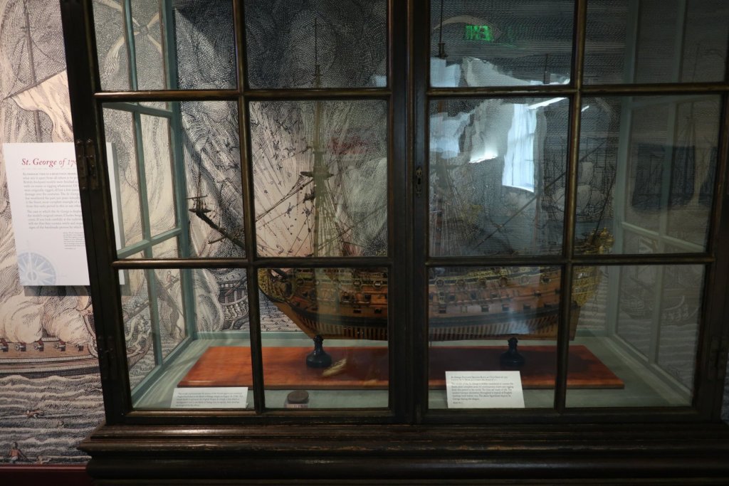
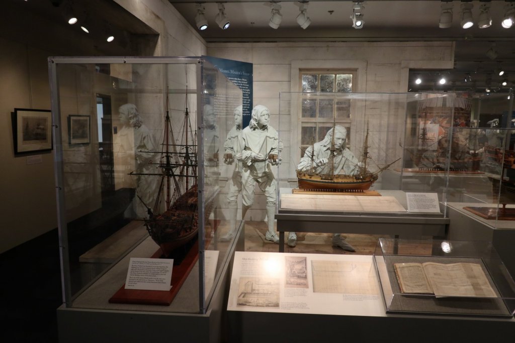
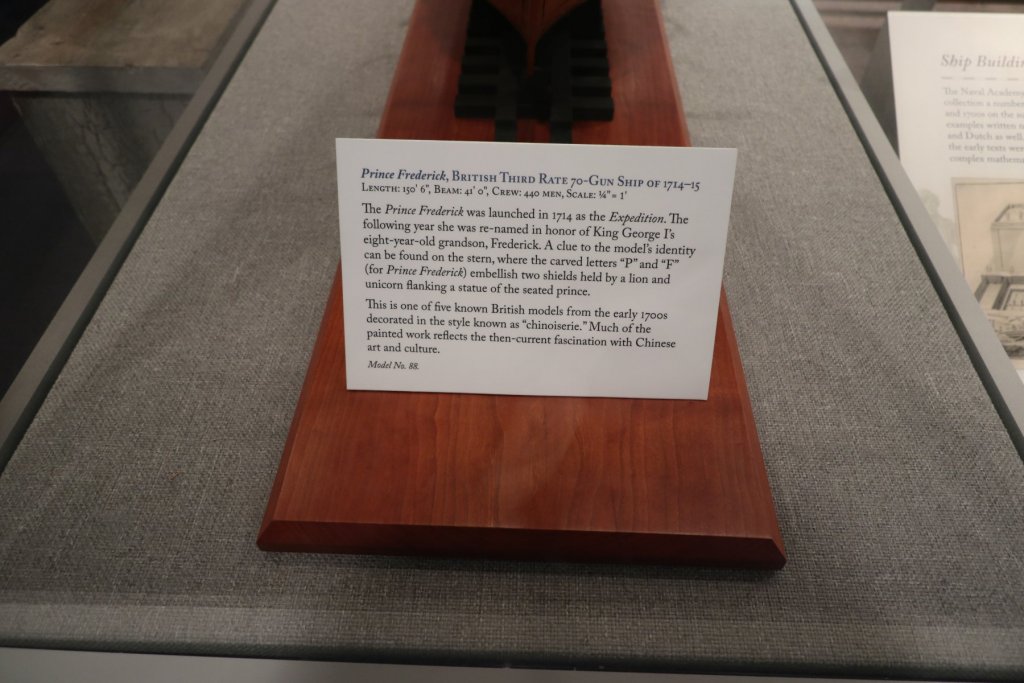
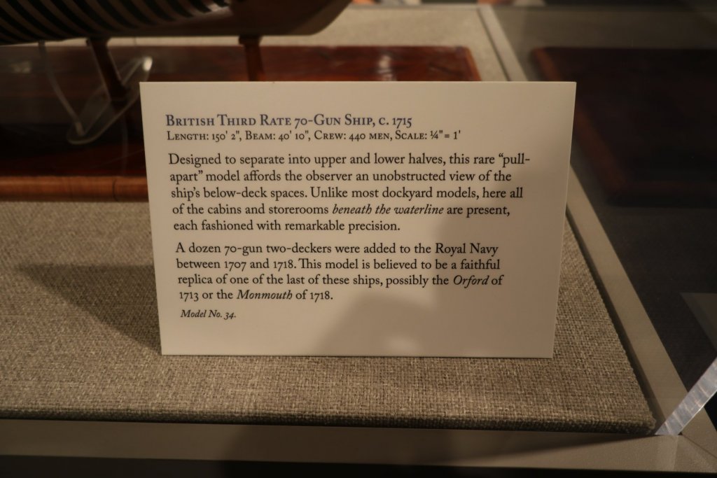
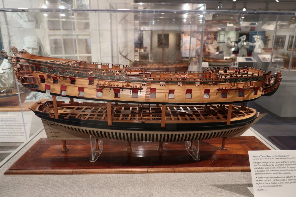
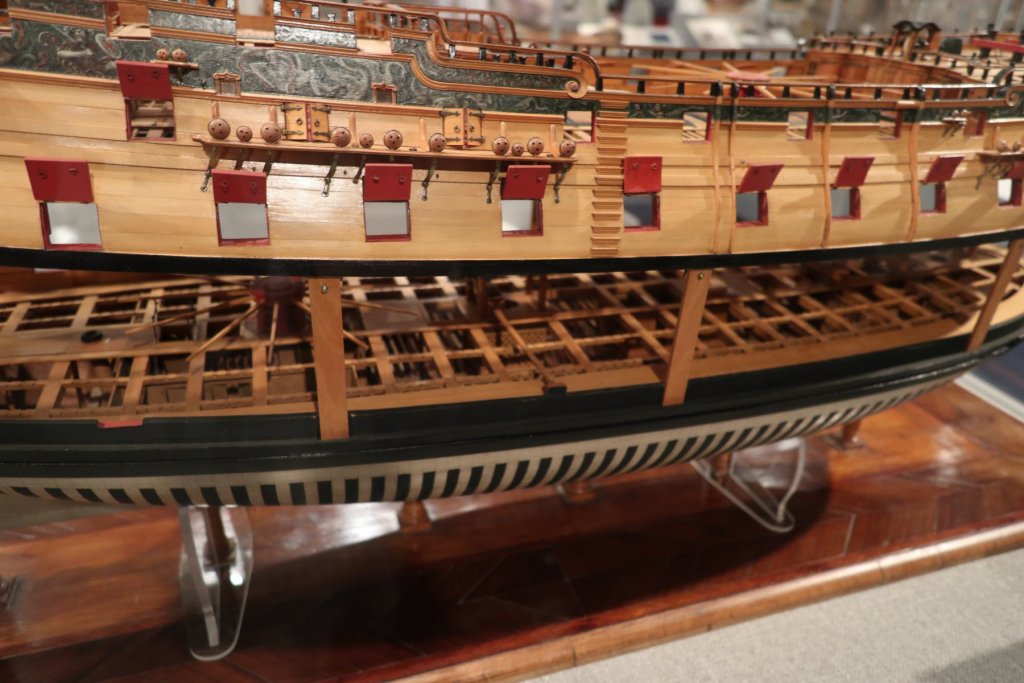
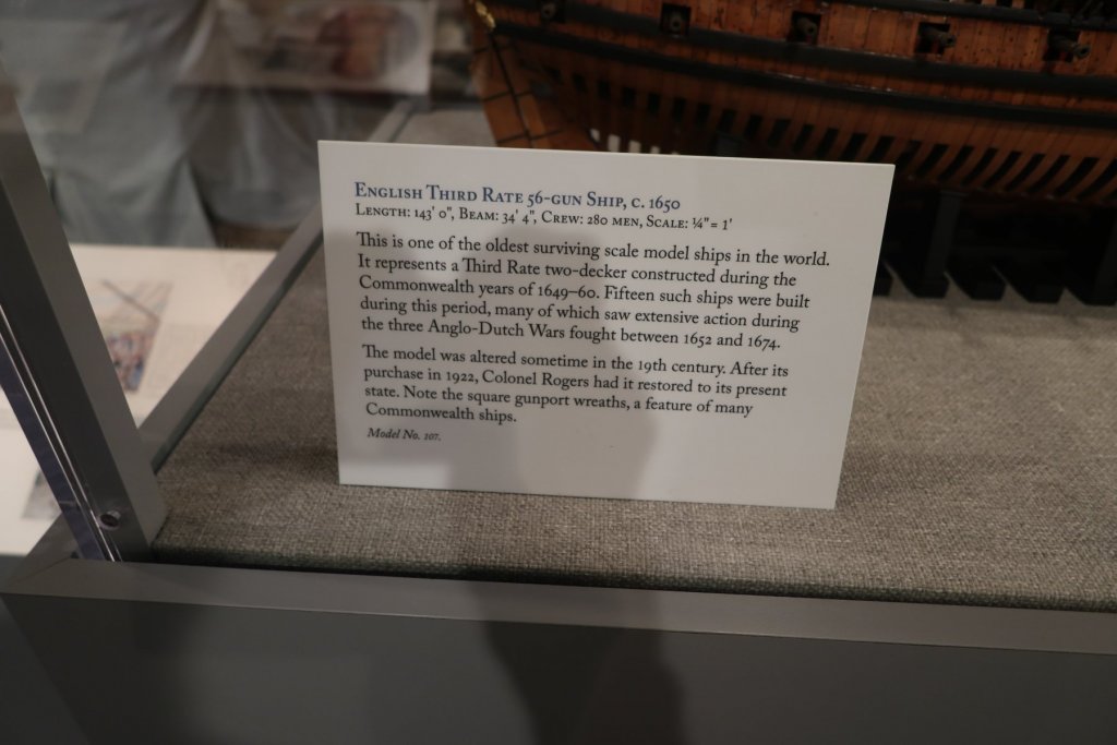
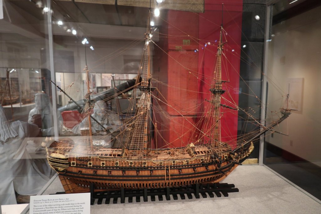
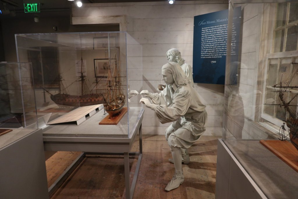
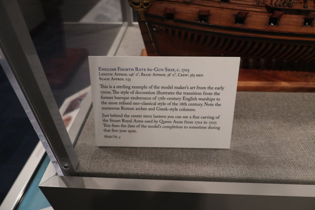
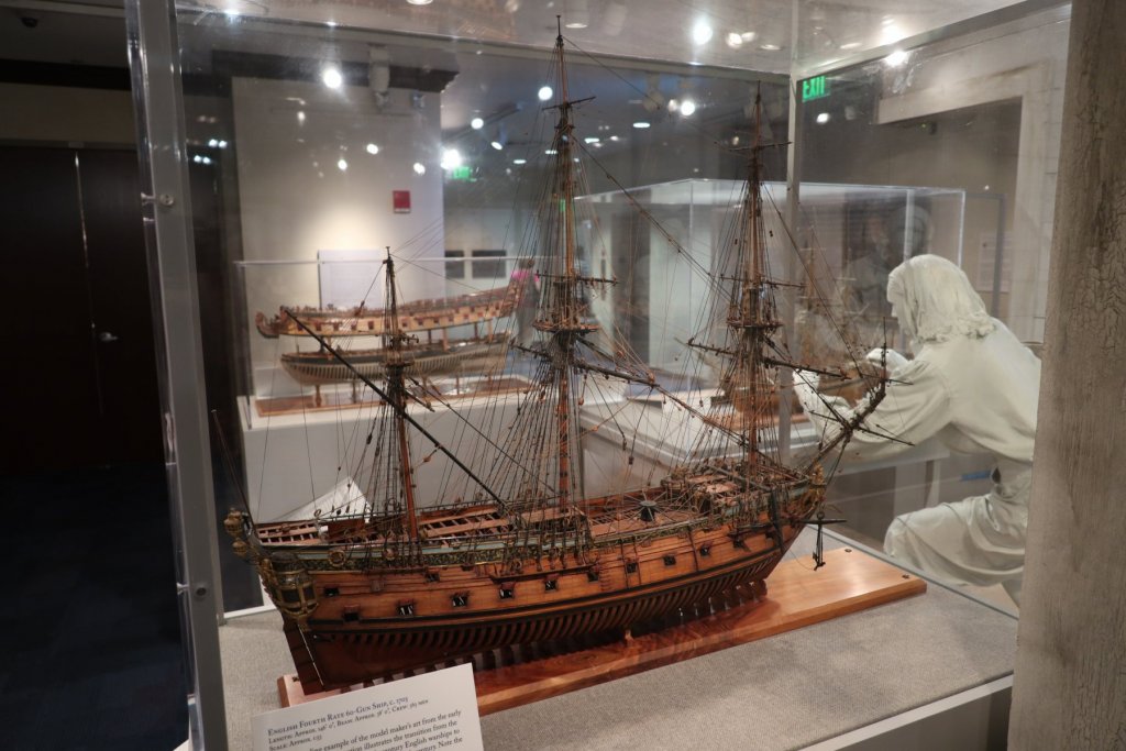
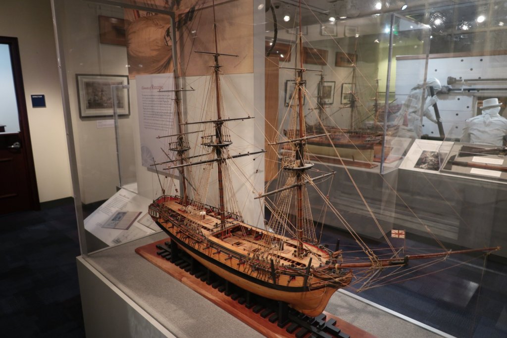
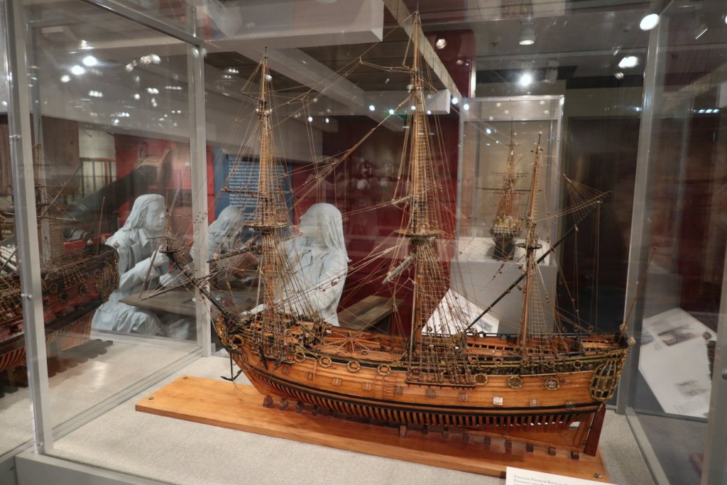
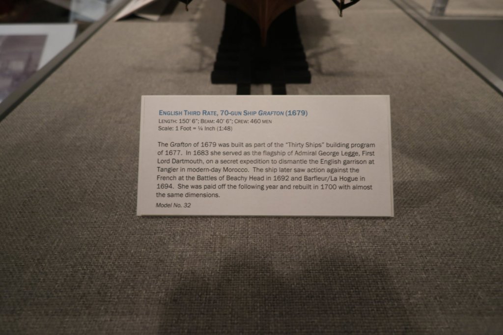
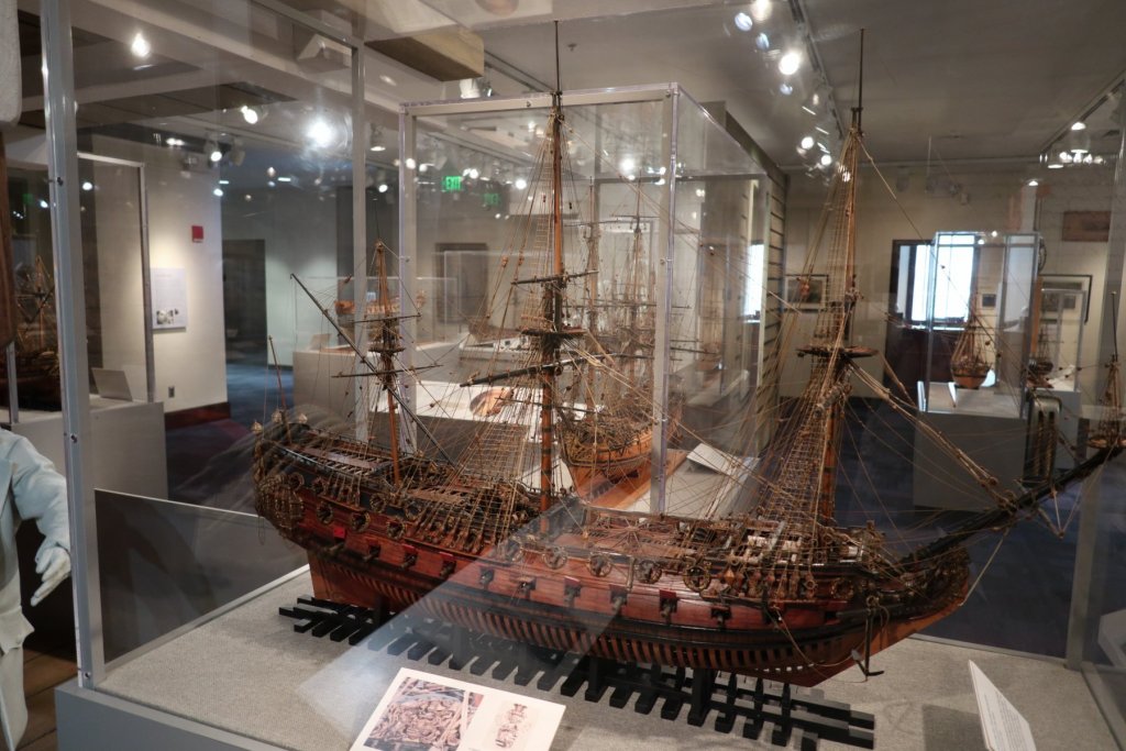
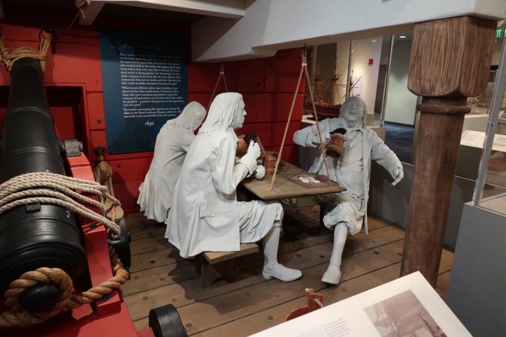
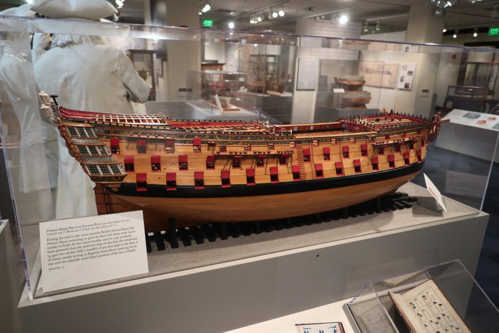
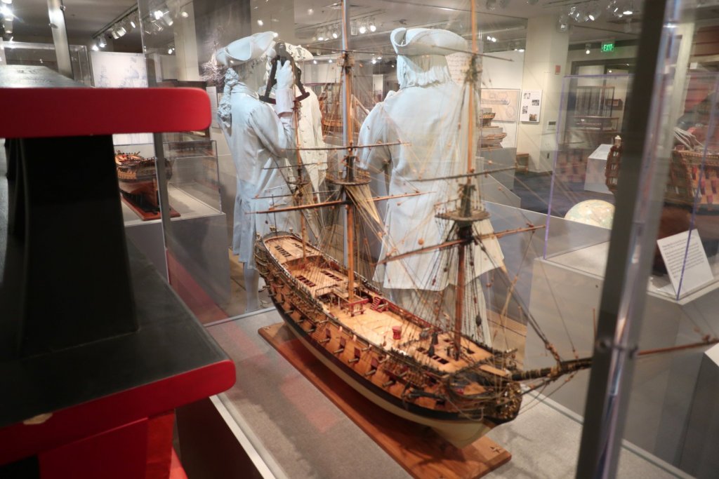
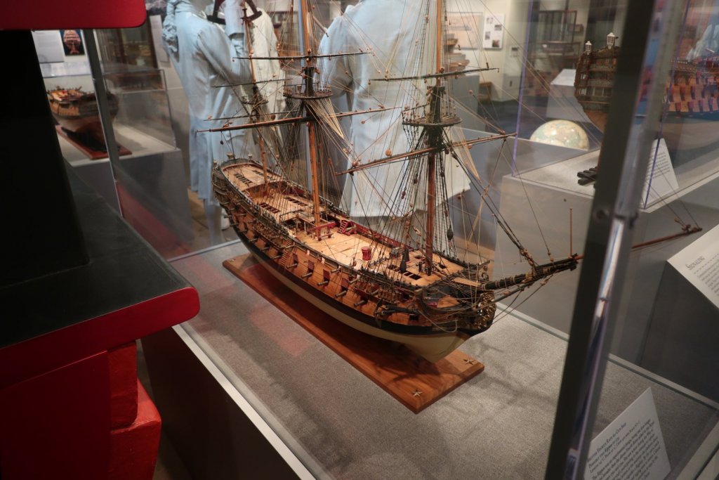
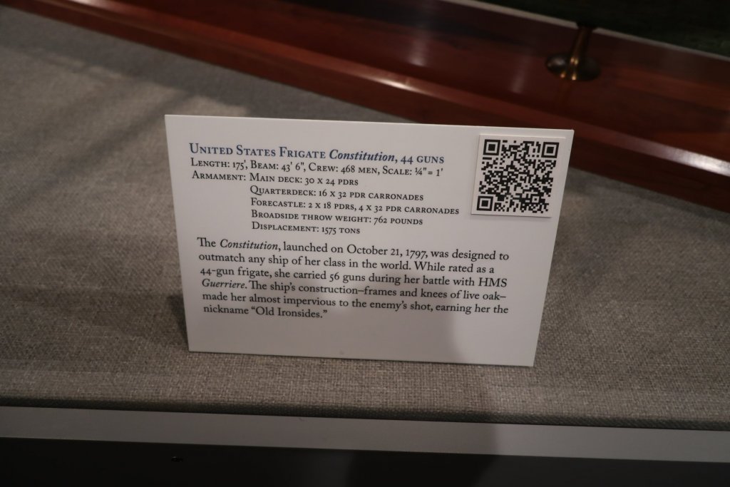
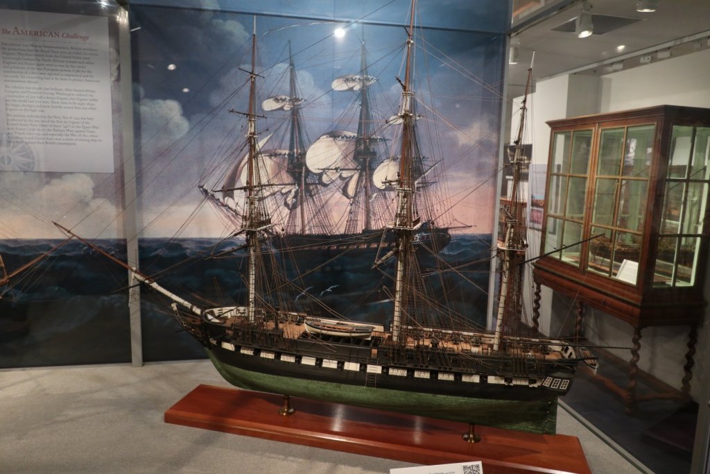
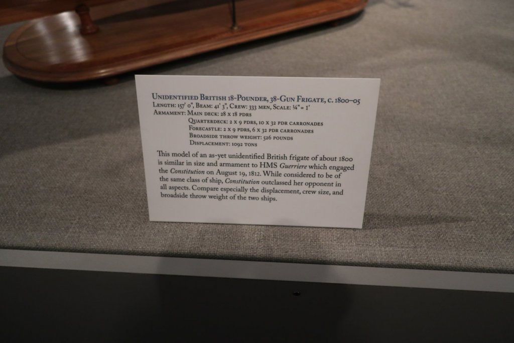
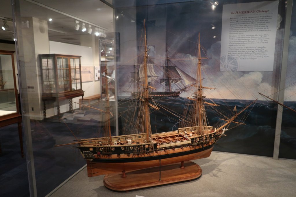
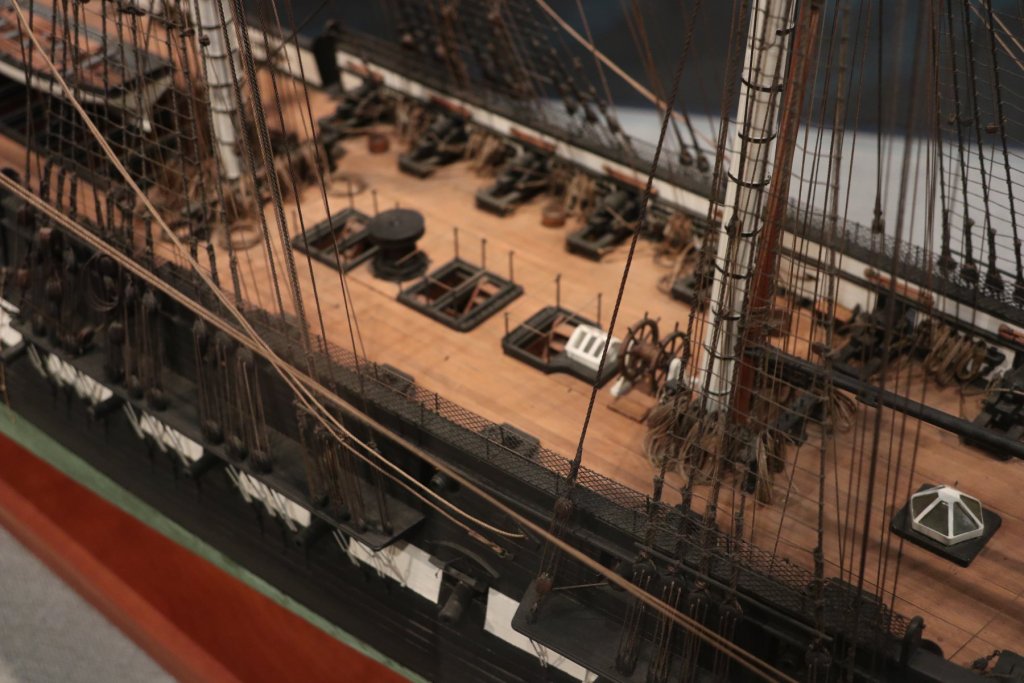
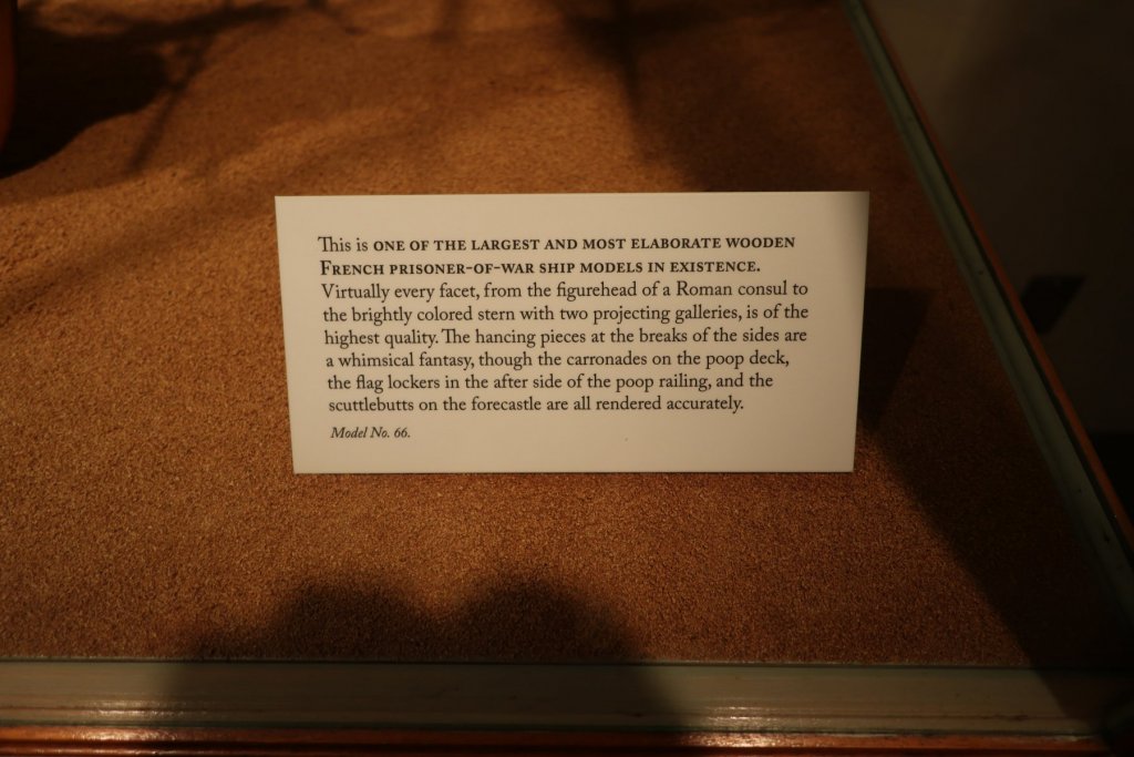
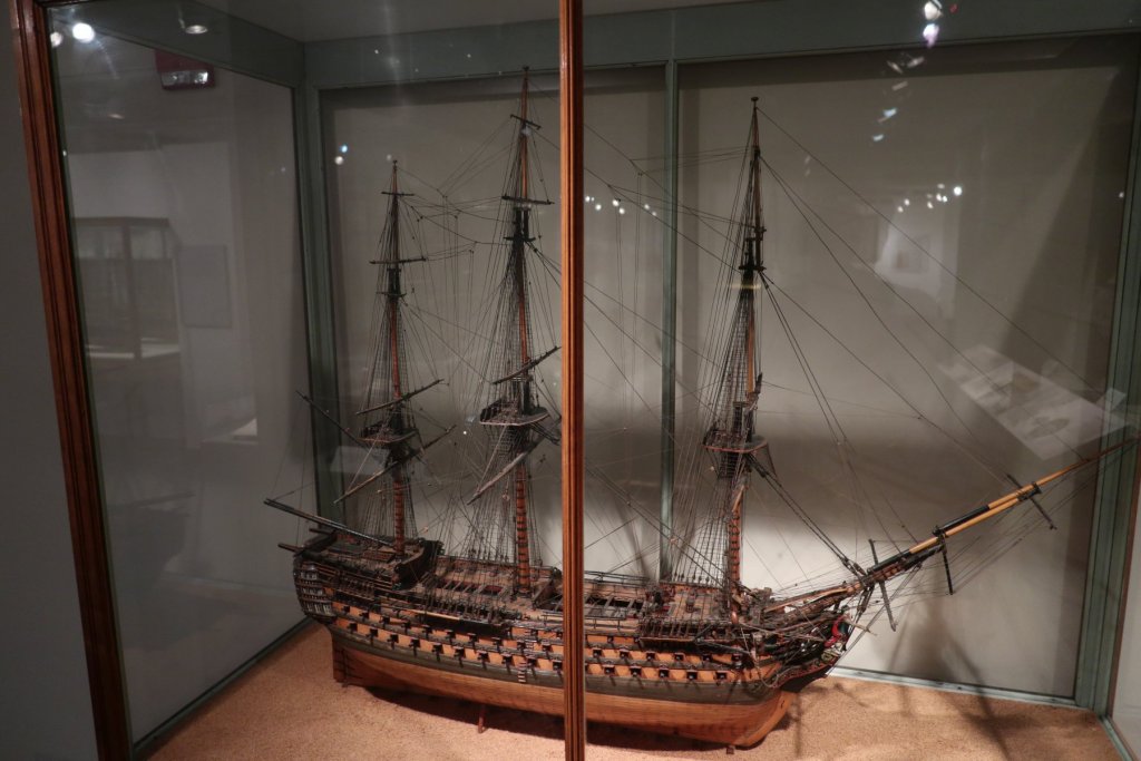
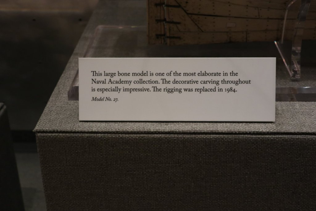
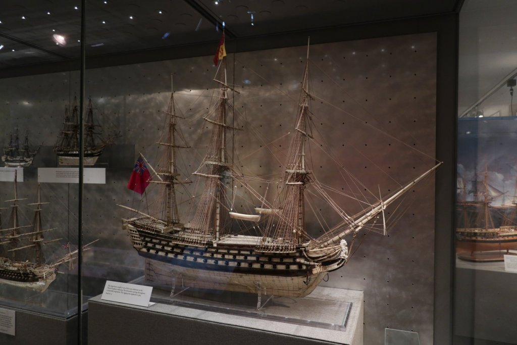
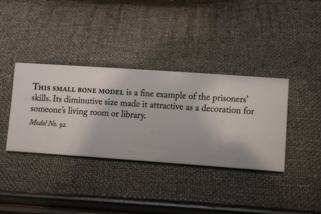
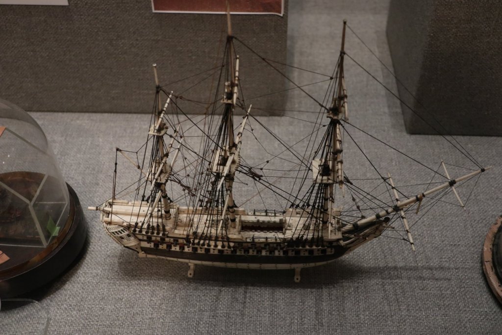
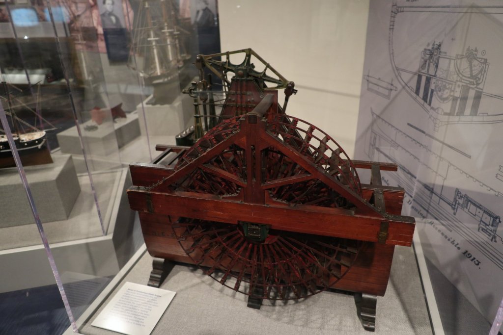
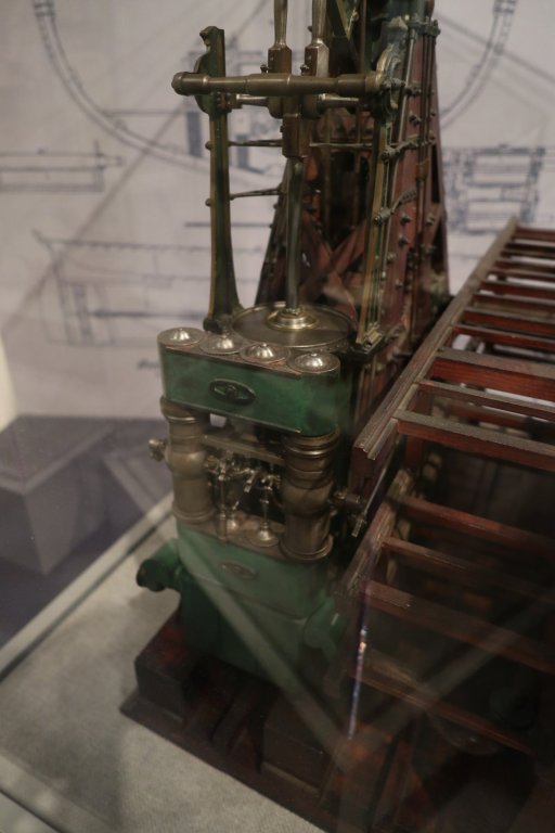
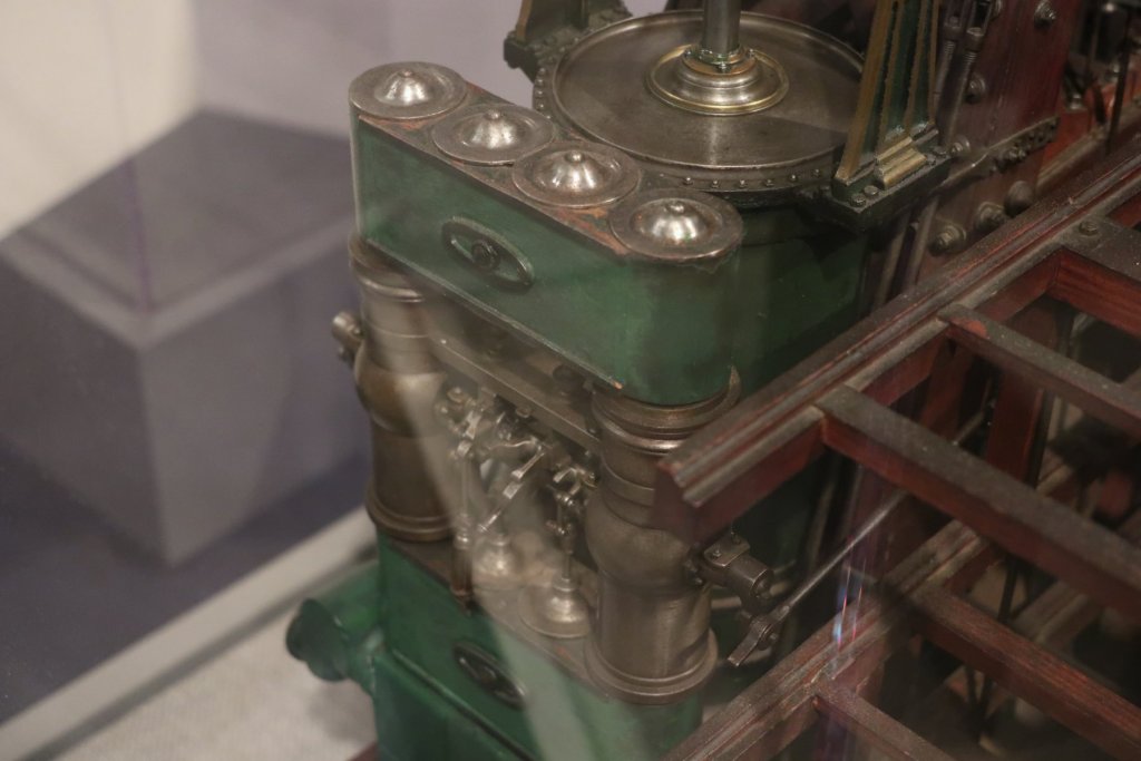
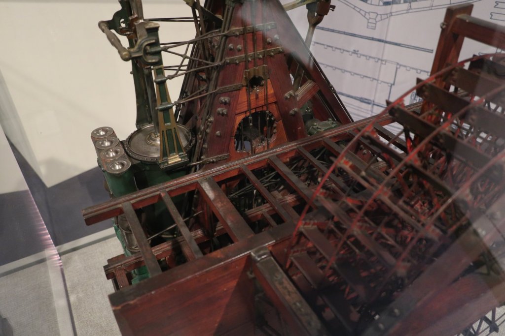
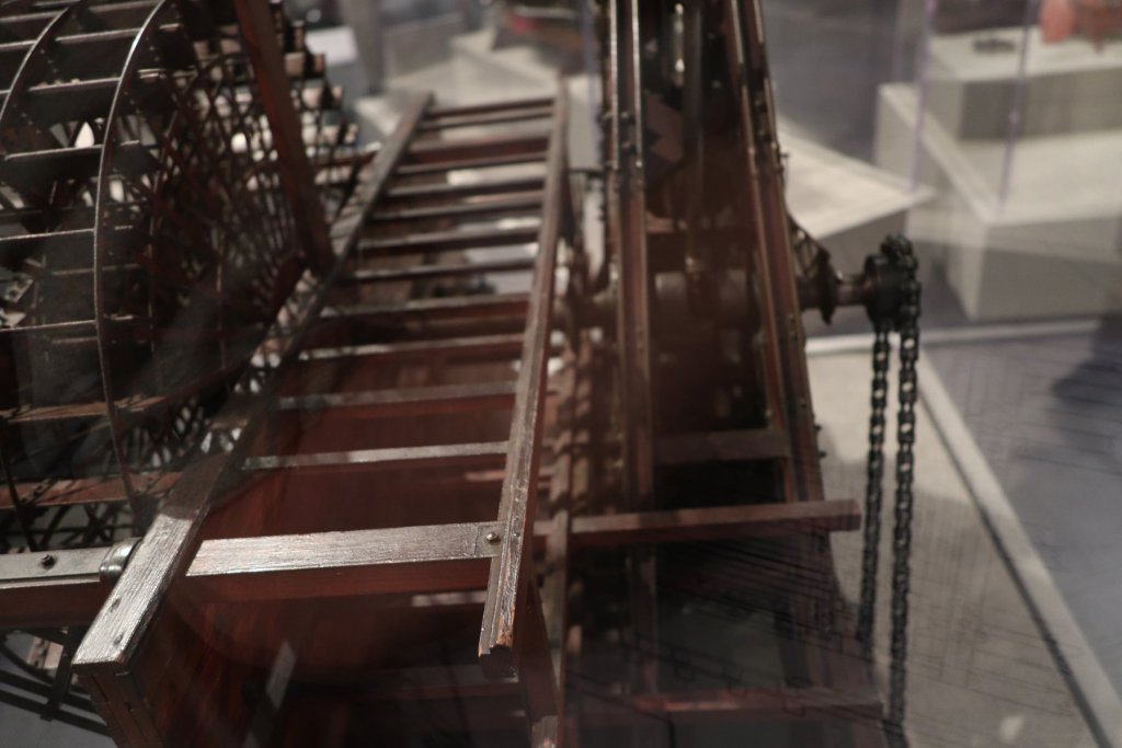
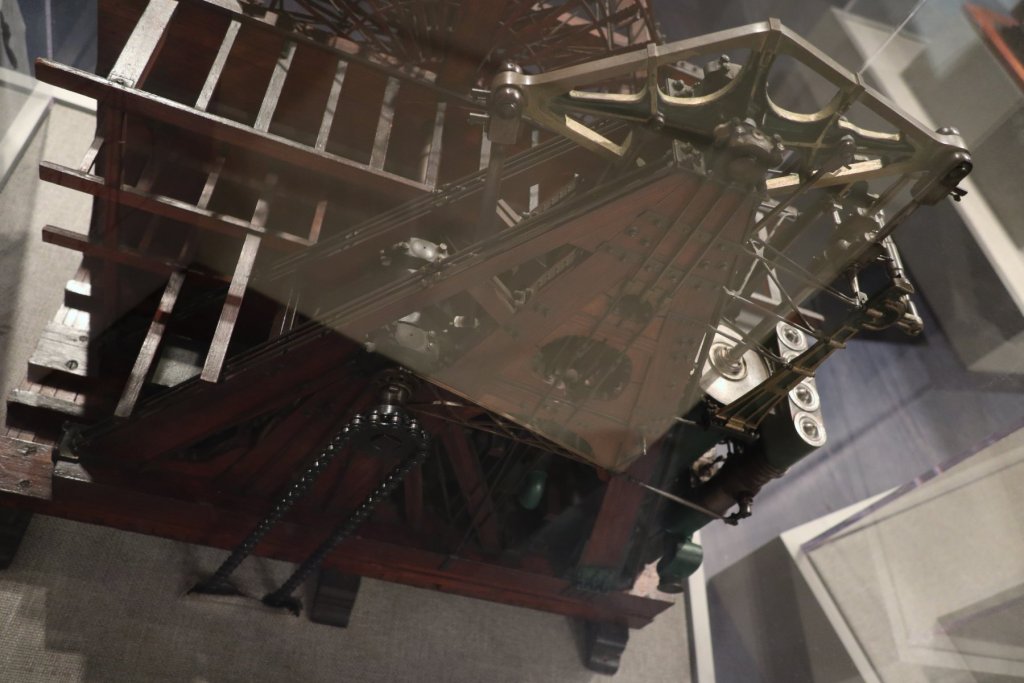
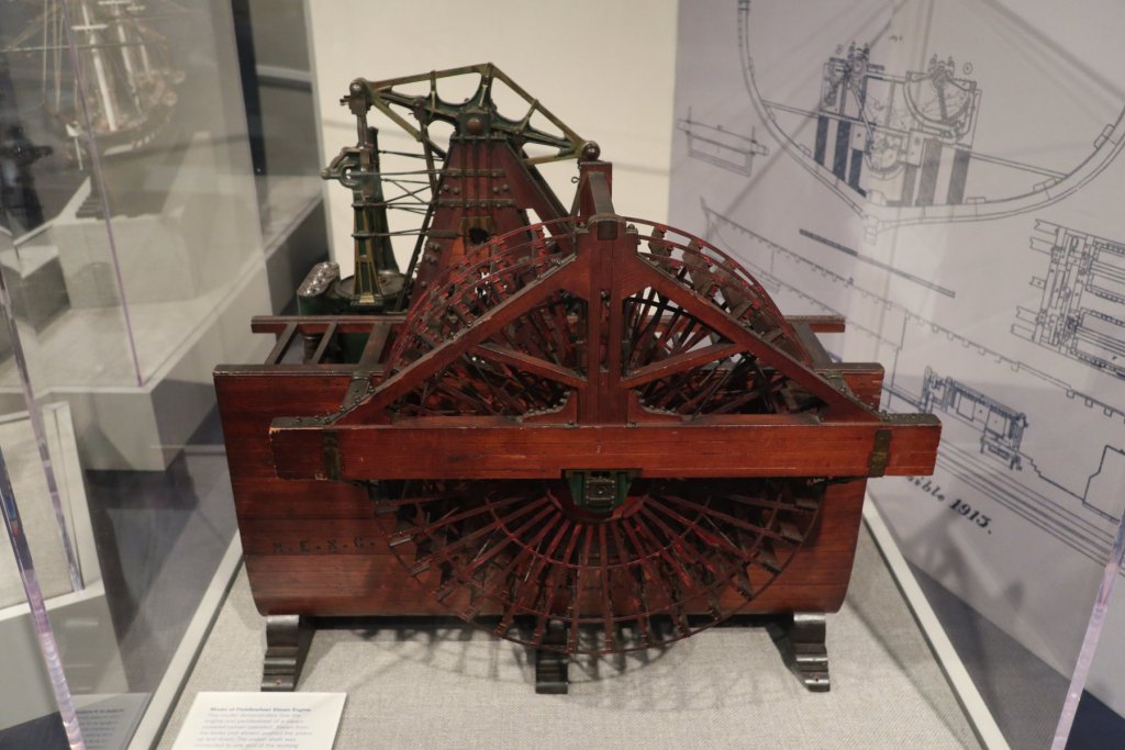
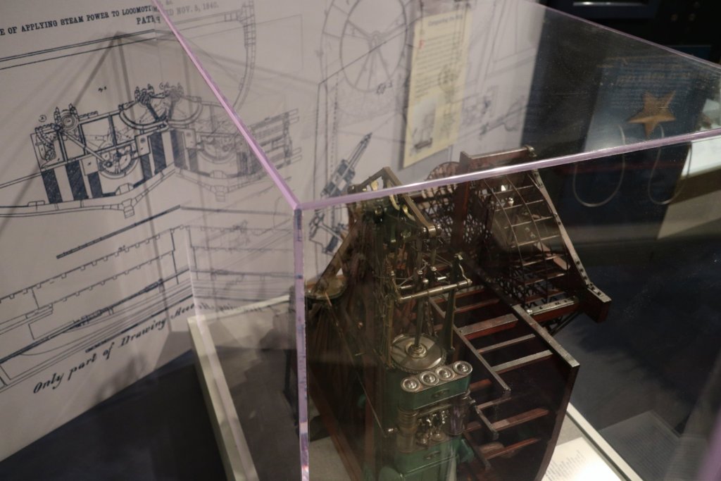
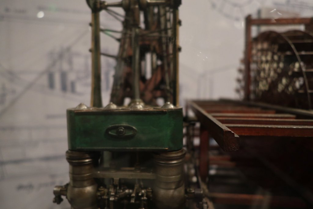
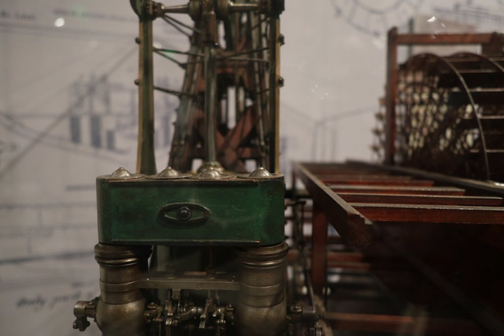
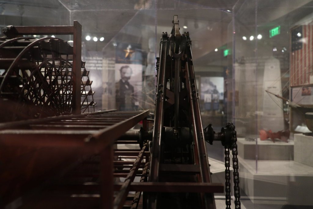
Other photos from the Annapolis Naval Academy Museum. Some of these models were 5 feet long. At least one is considered to be one of the oldest models in existence, built in 1650! If you are in Maryland and get the opportunity, try to visit the museum. I tried to keep the placard photos in line with the ship, but one or two may be out of order.


-
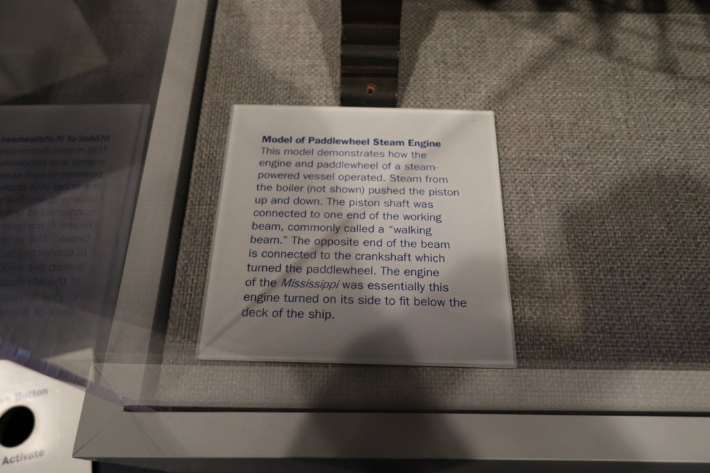
I went to Annapolis to visit the Naval Academy Museum. They have quite a collection of models and other items. Some of the models are as old as the original ships. They have a model of a walking beam engine. It is displayed in a position where it is difficult to get a shot of the back of it. Also, it is attached to an electric motor and gear so you can see how it worked. That part was out of commission, but there is a youtube video of it. Here's a video of the walking beam engine I took. If it doesn't work, message me. Walking beam video Here's a few pictures I took while I was there.


-
John, Your HO work is unbelievable! I love seeing it!
-
Here's a kit model for anyone that likes walking beam steam engines - it is 41" tall and over 175 pounds! It could be one heck of a build log! https://downrivertools.com/marine-beam-engine-castings-and-drawings-set.html (This link appears to be unavailable as of 07/18/2020. Really cool model though!) It interests me that the walking beam in the kit photo is red. I noted that Dan painted his red, and the 1996 kit has a brass walking beam with red tinting - see the brass photos in the 1996 kit section. After reading RFP's post, I went on youtube. If I read it right, there is a video of a working walking beam engine that is being used in an RC paddle wheeler. There is also a video of a walking beam model at the Naval Academy. I'm an hour away from there and will go and get some photos of it. I'm not going to go crazy, but I'd like to represent the engine as best as my skill allows. I may reconsider using the red tinted walking beam from the 1996 kit. Here's the link for the walking beam engine the builder is using in a RC paddle boat: RC paddle boat
-
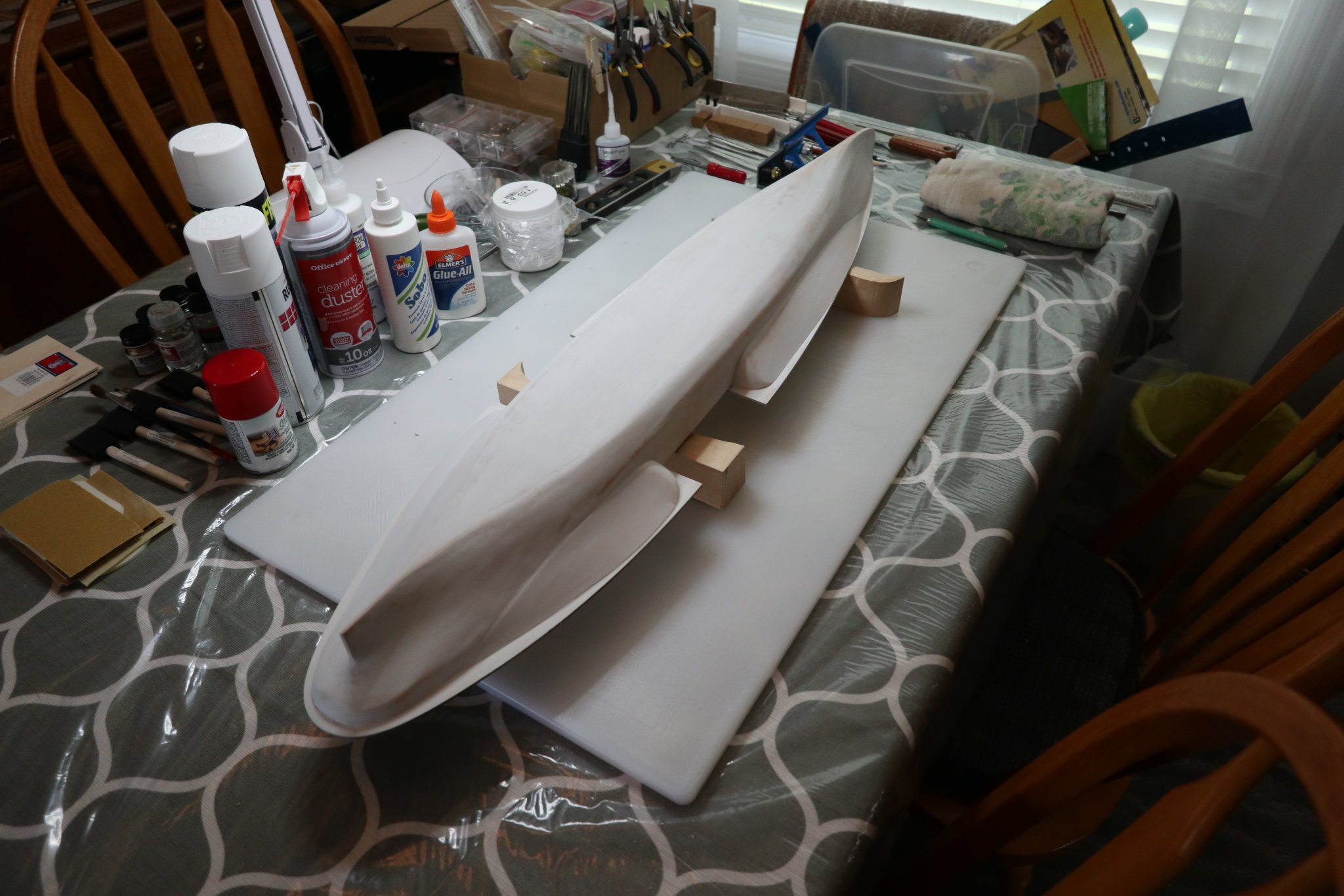
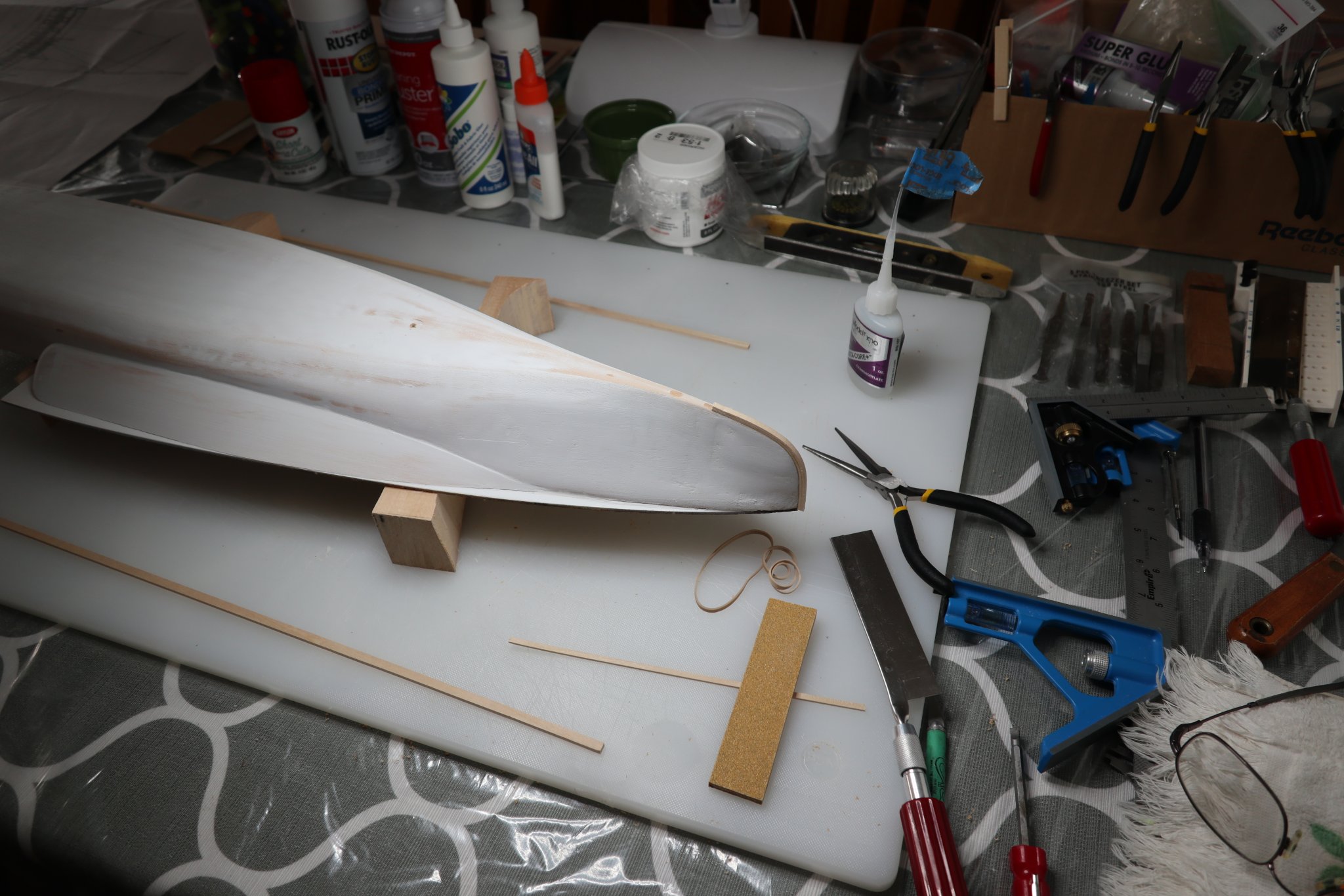
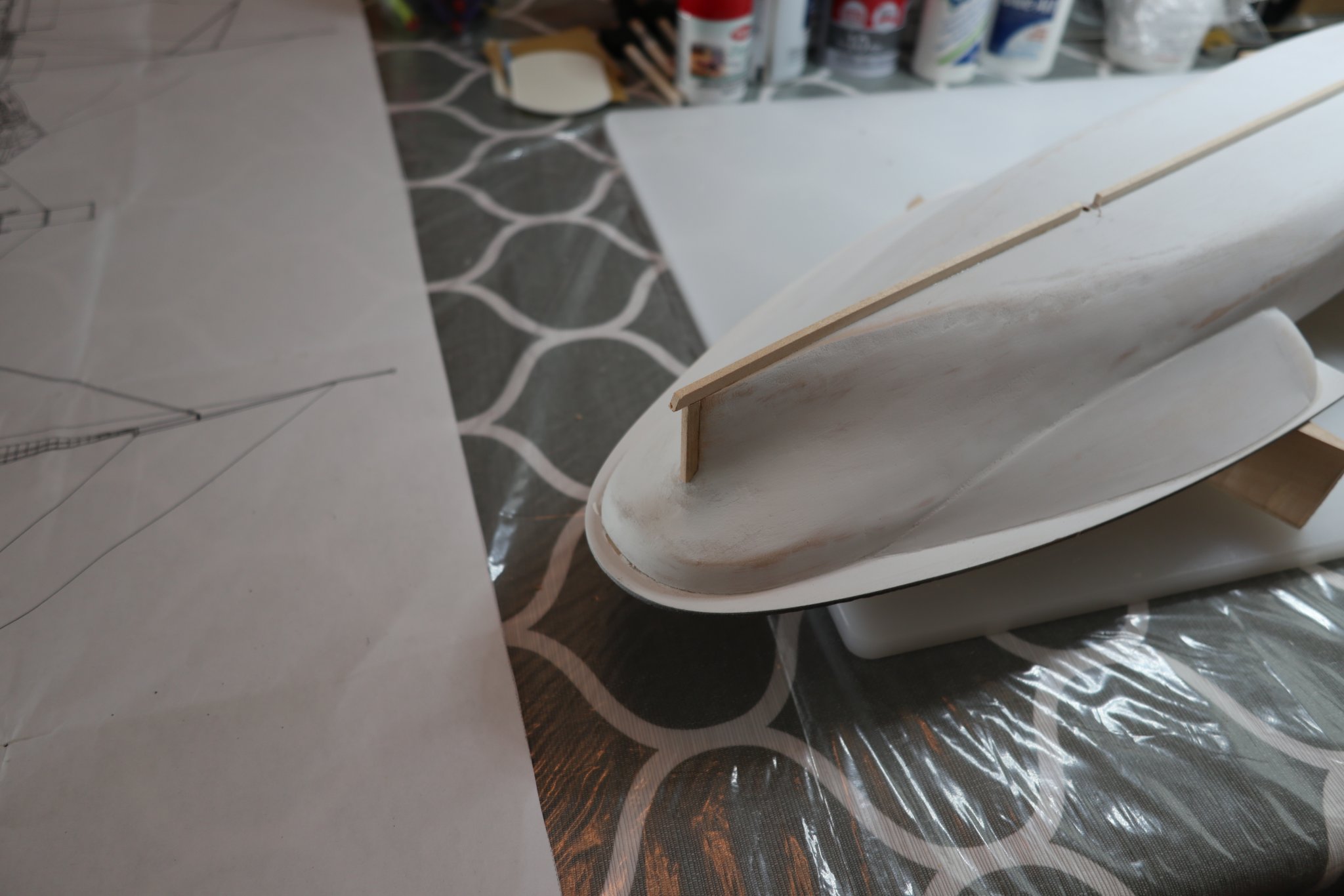
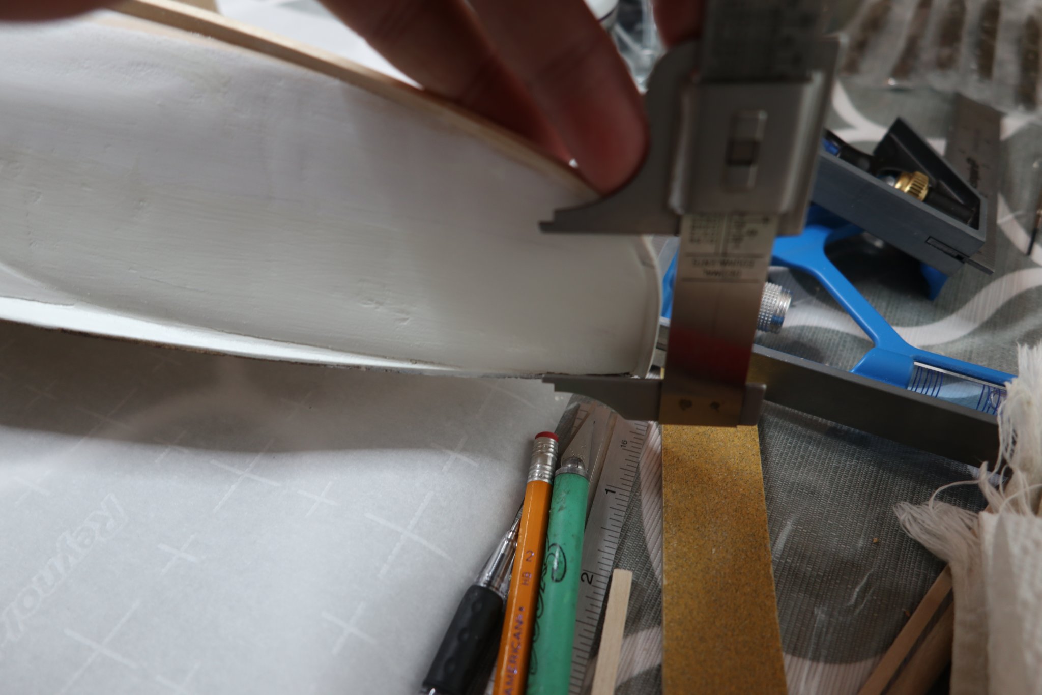
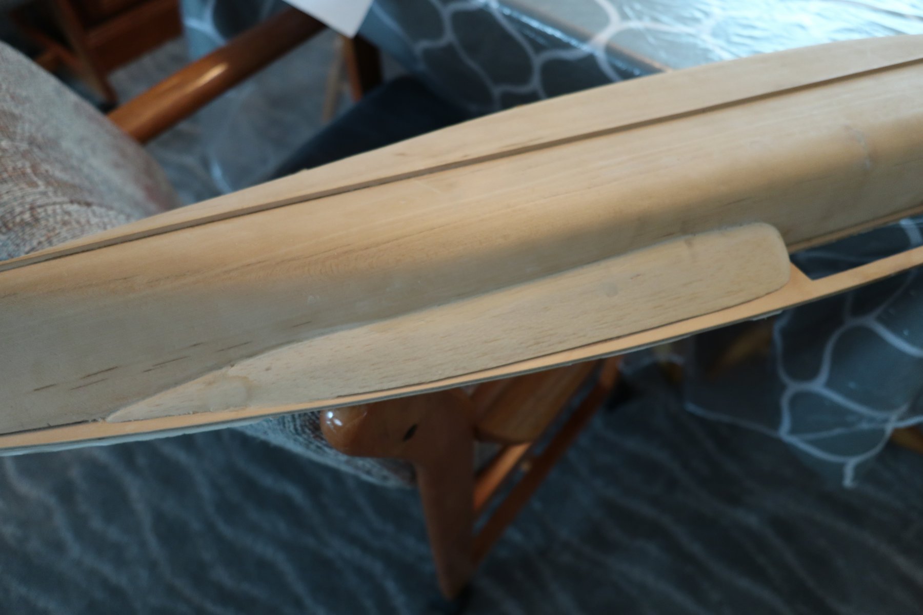
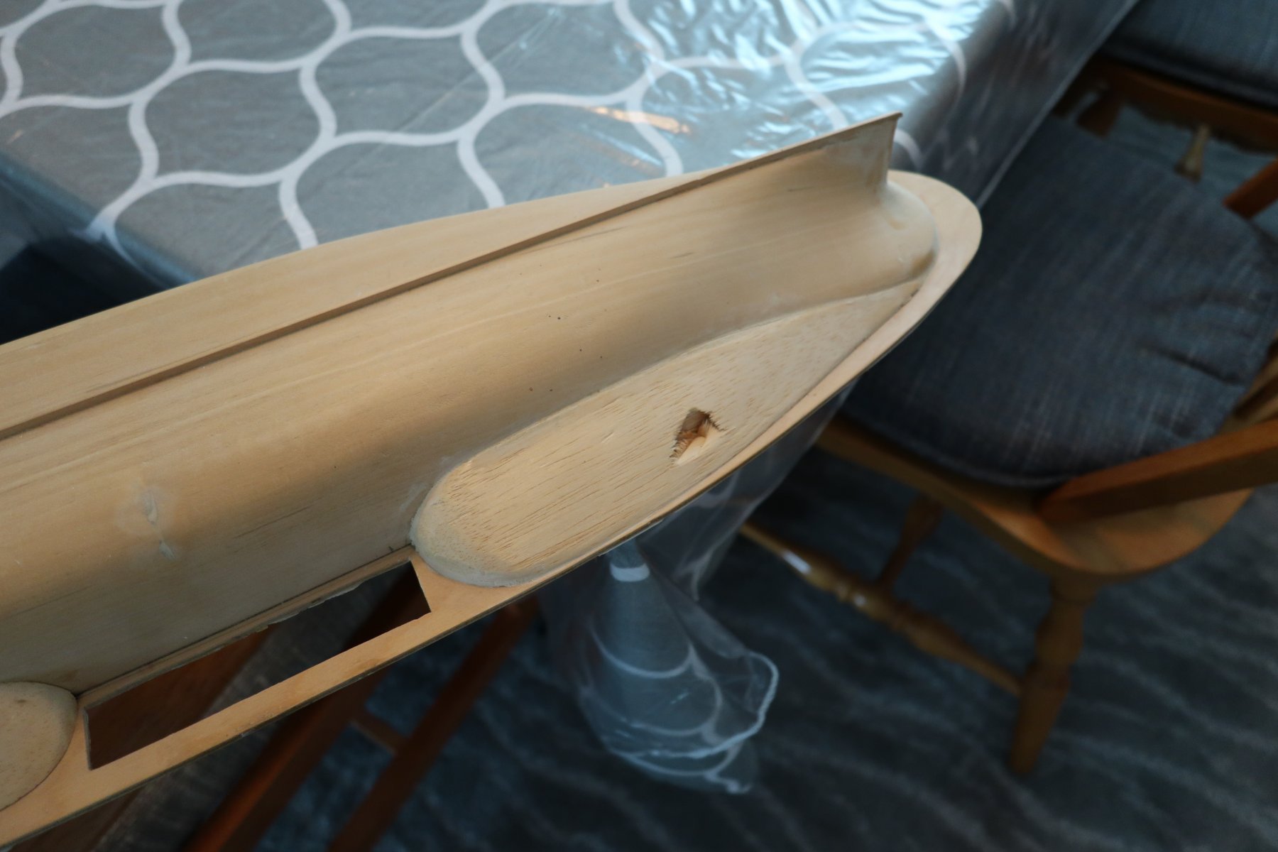
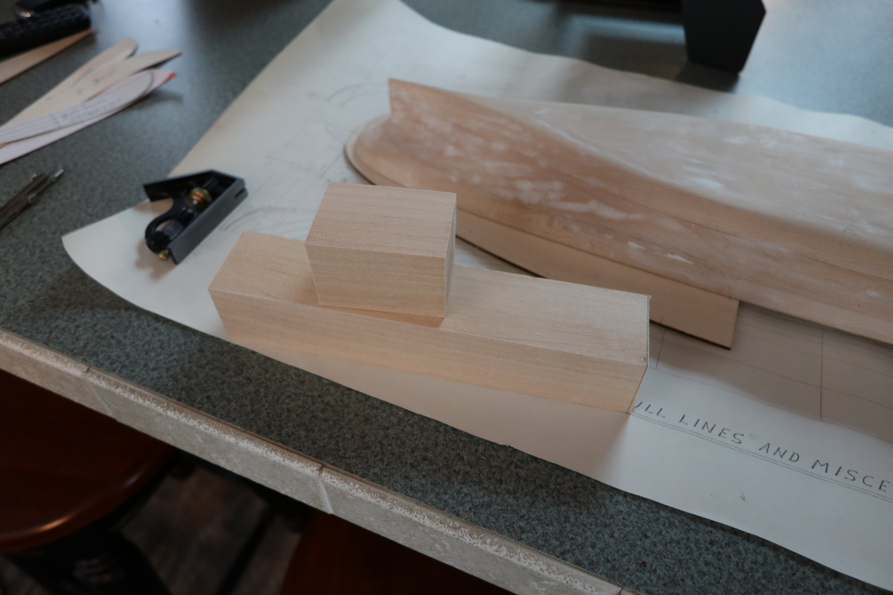
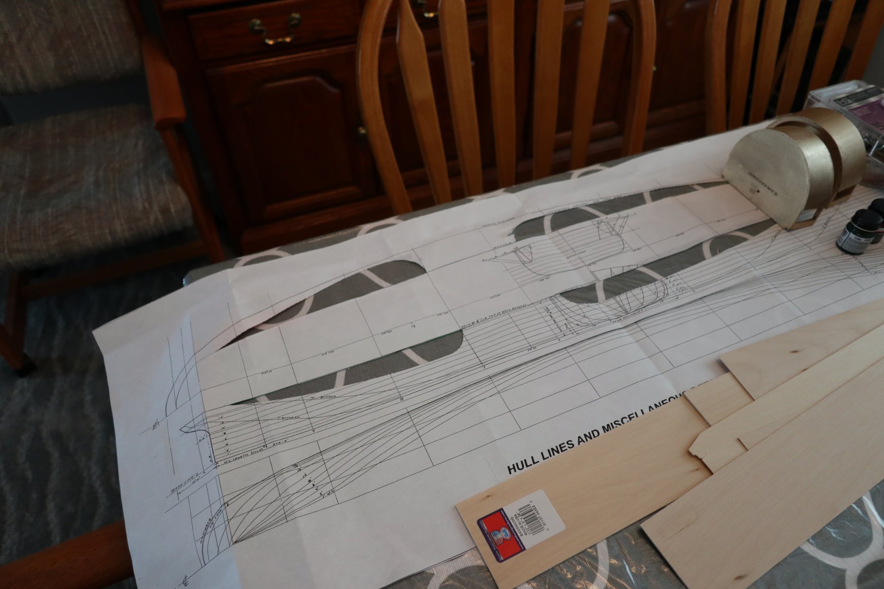
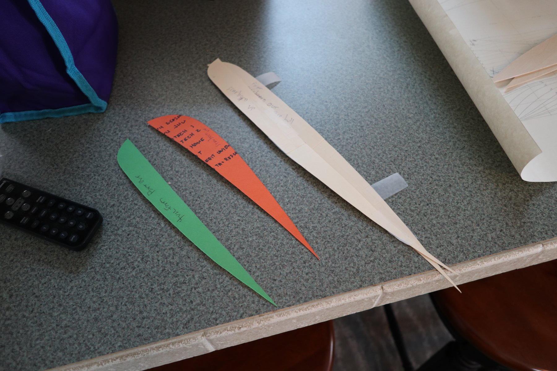
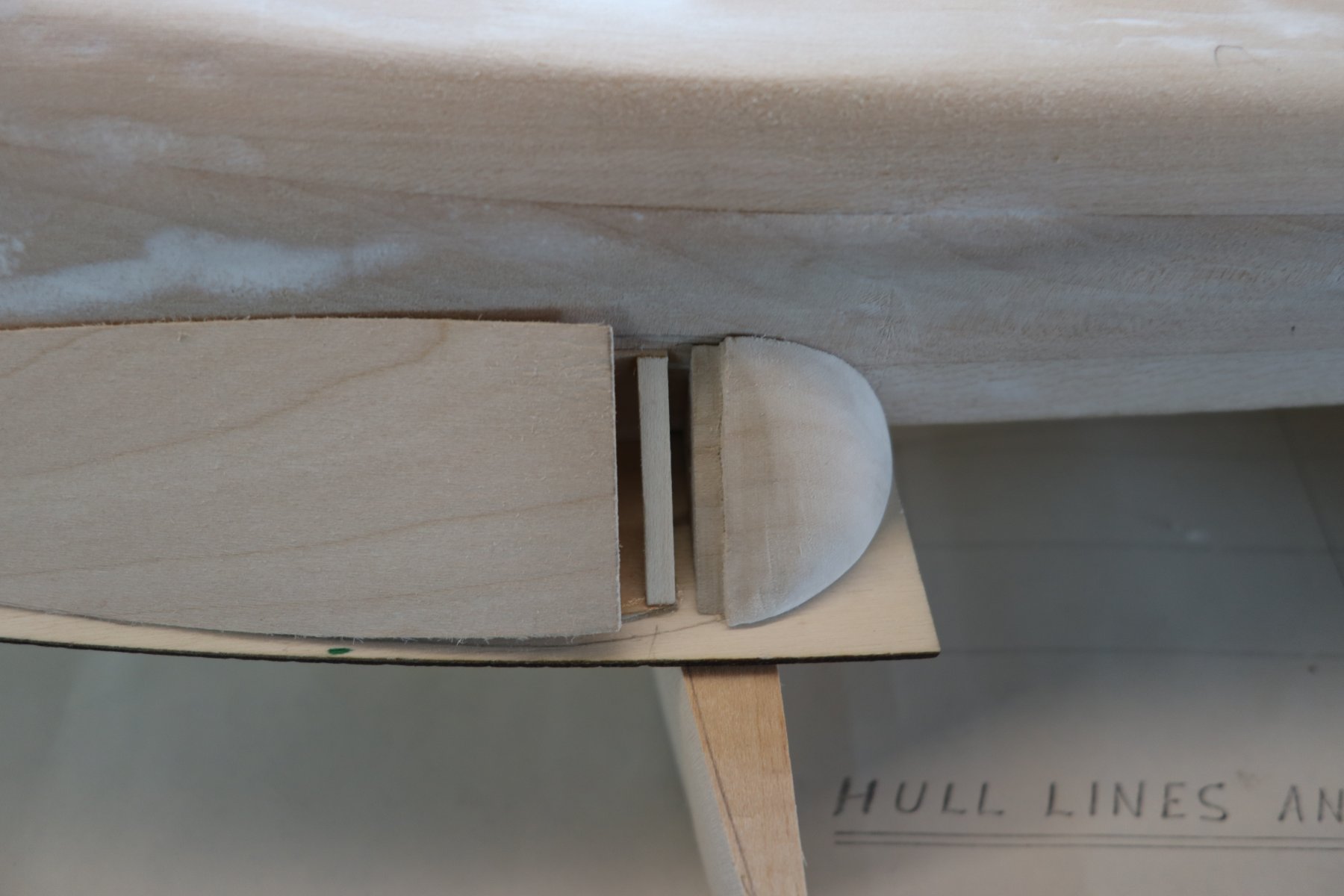
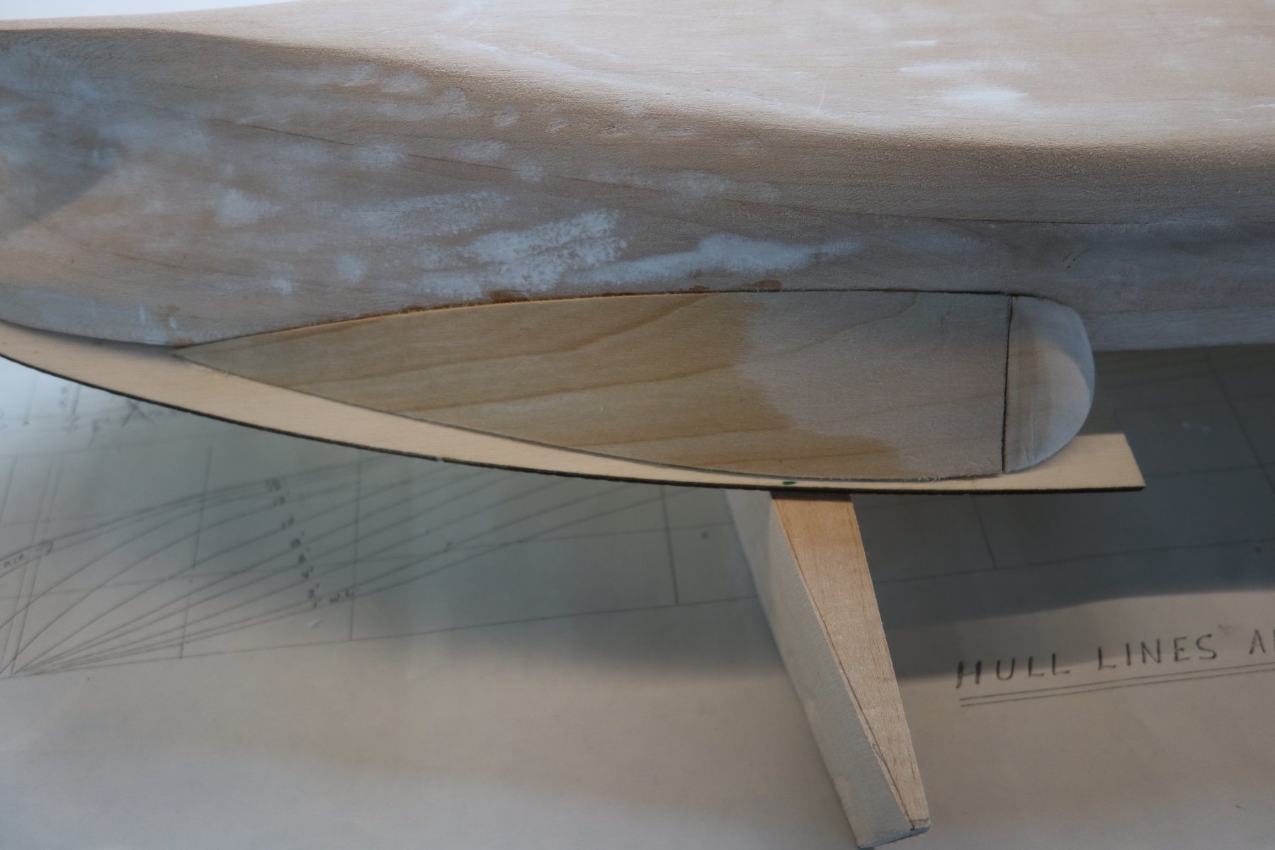
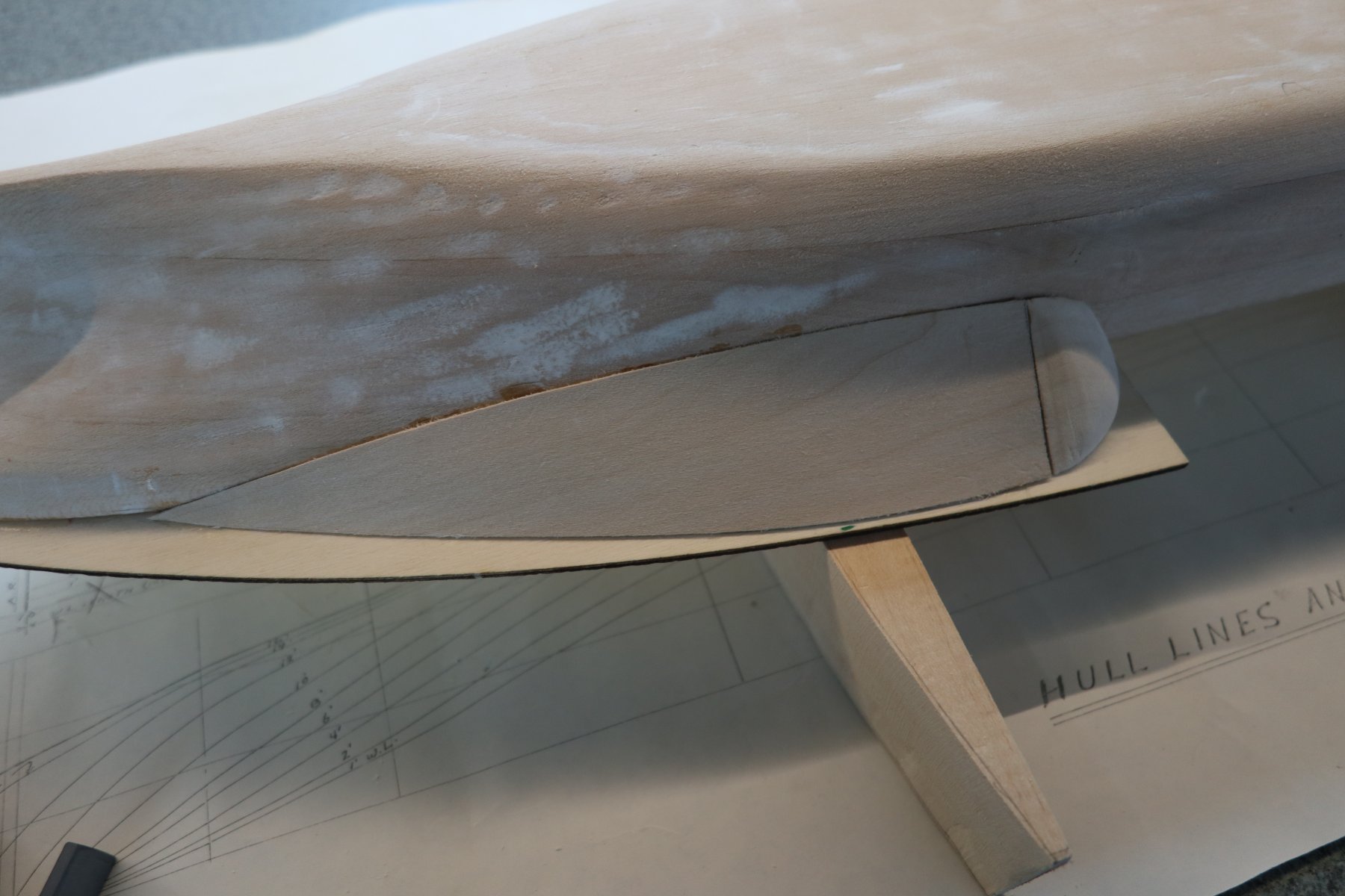
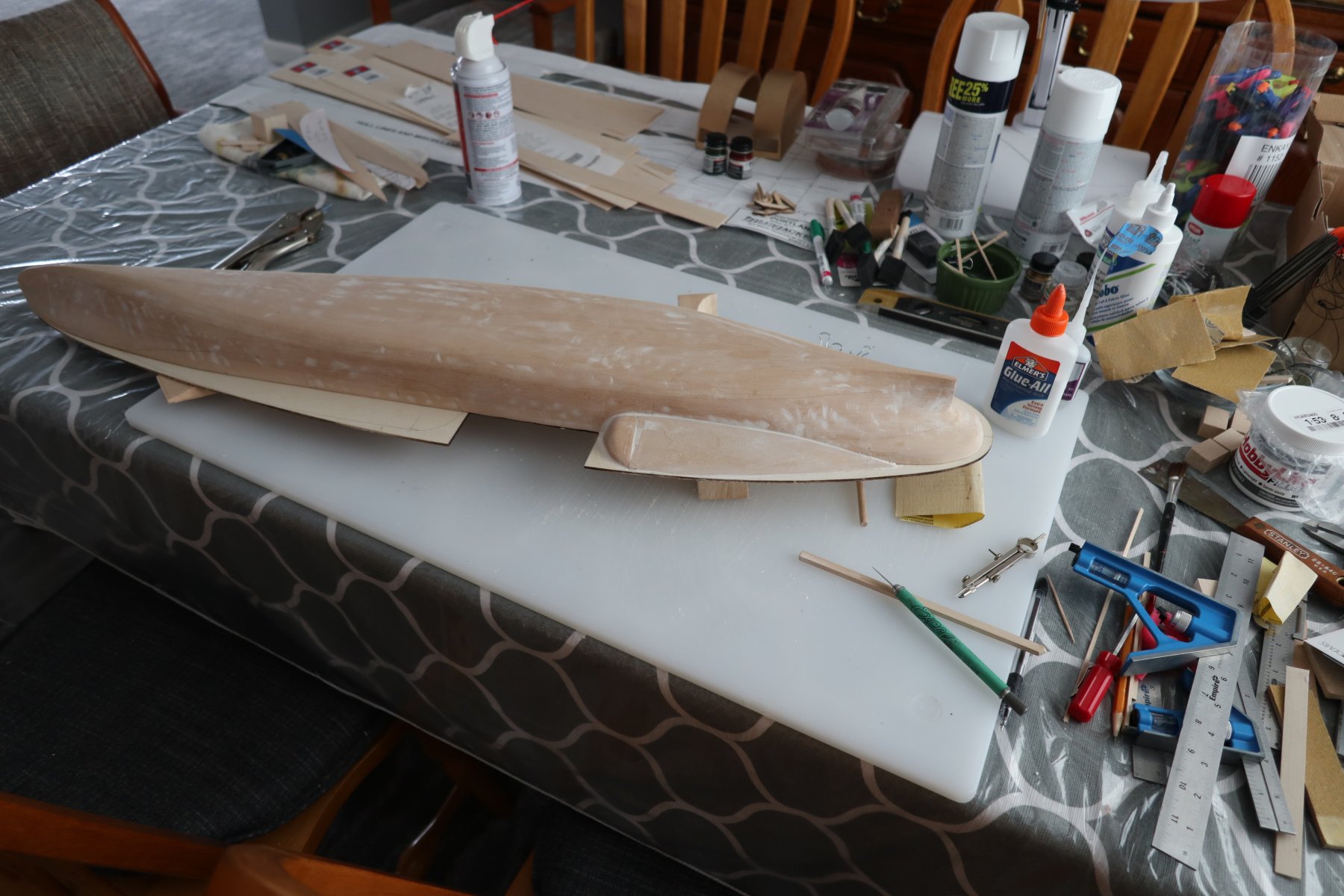
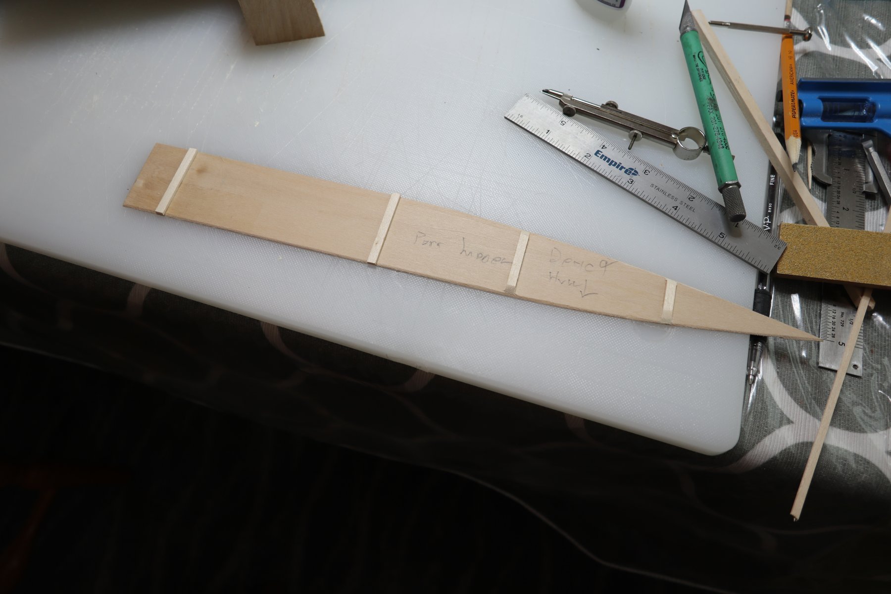
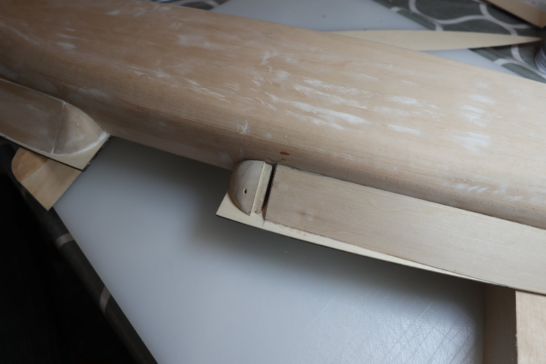
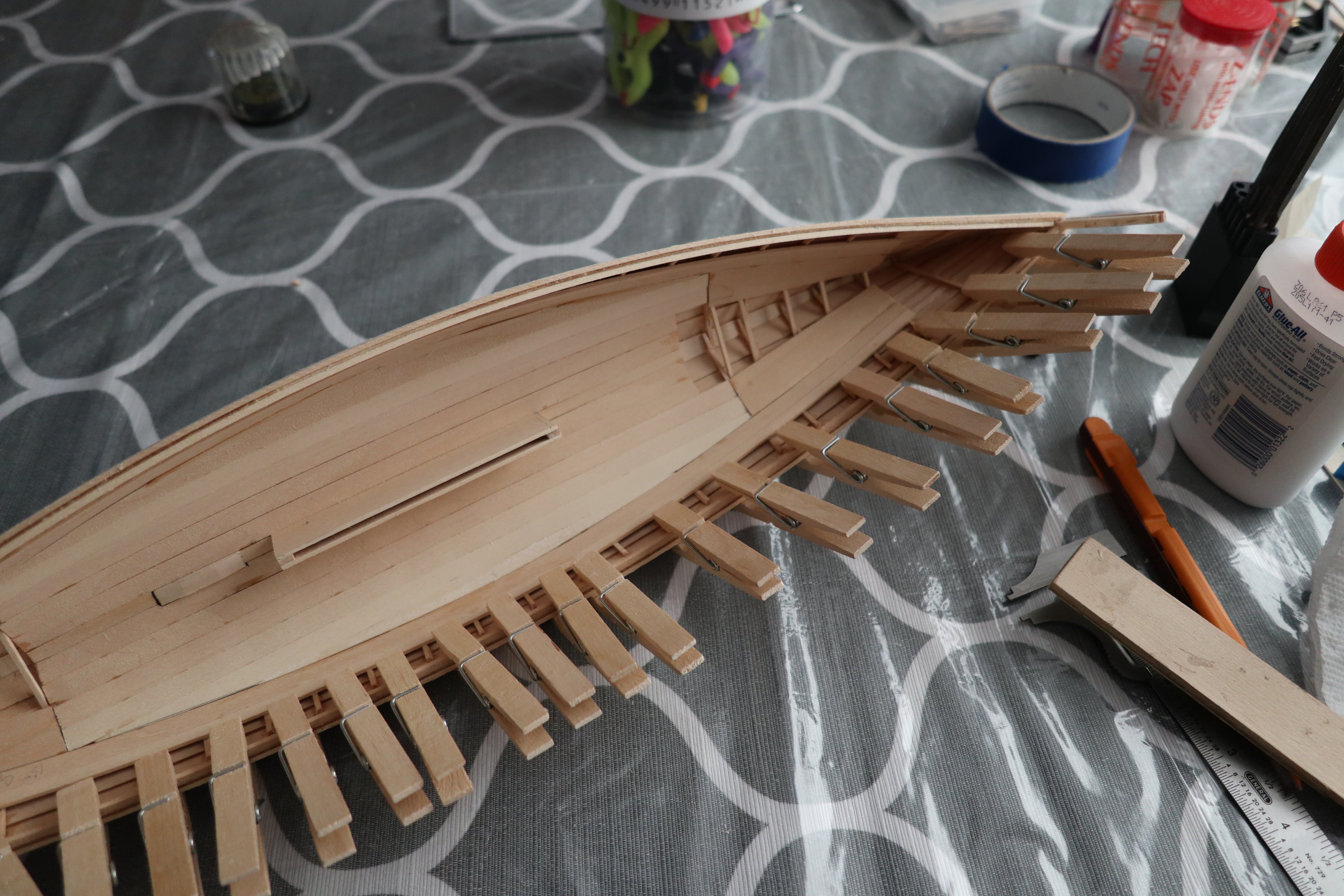
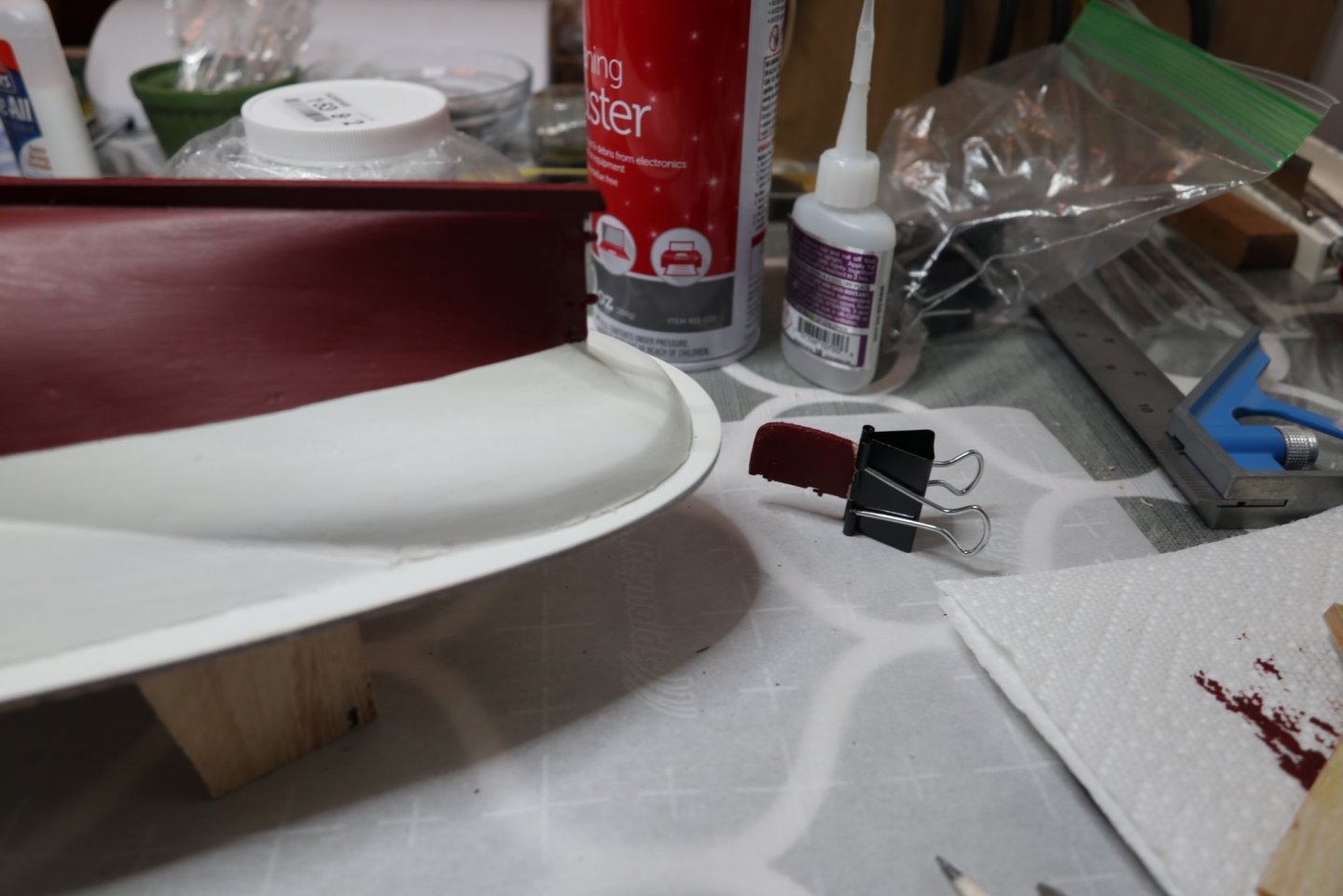
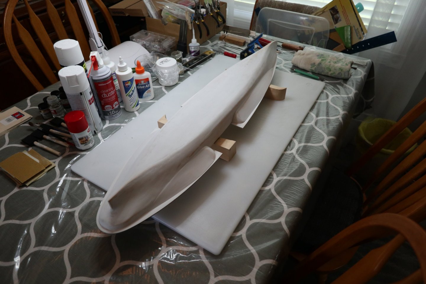
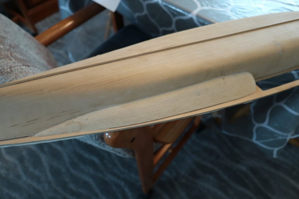
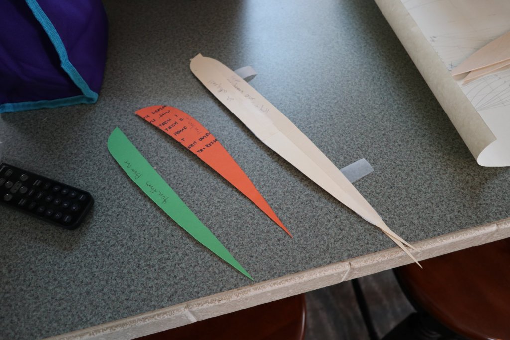
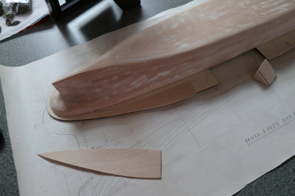
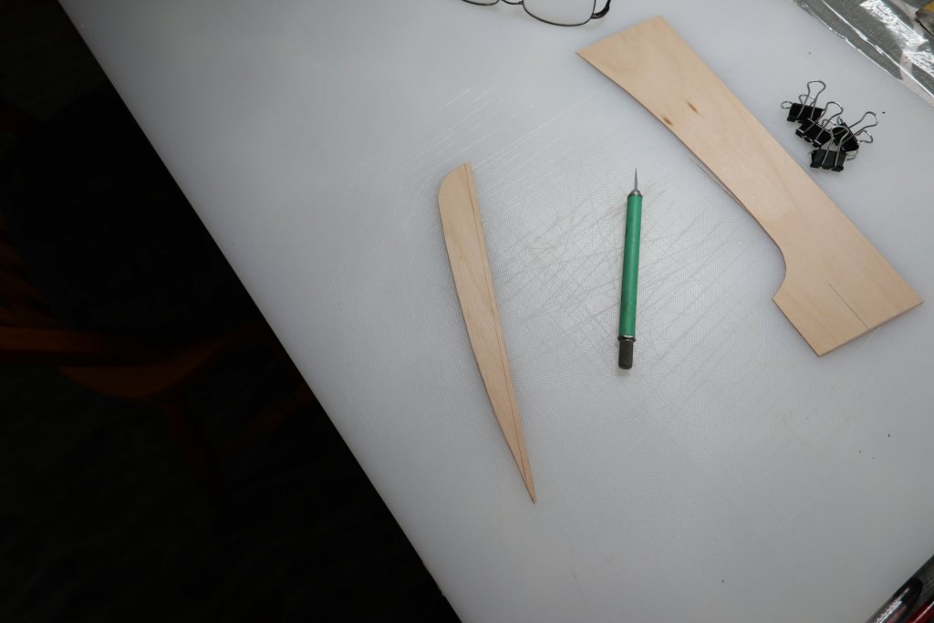
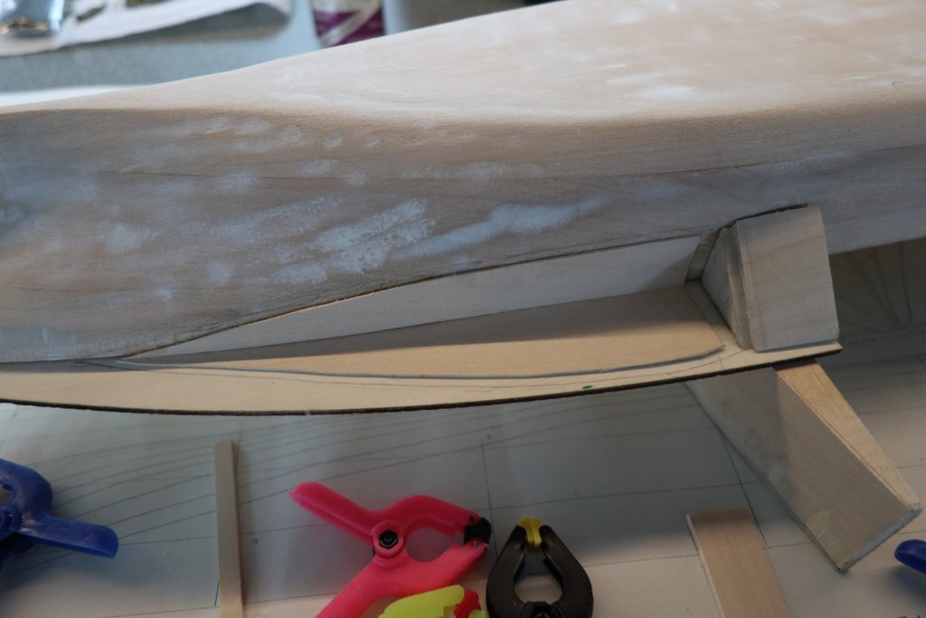
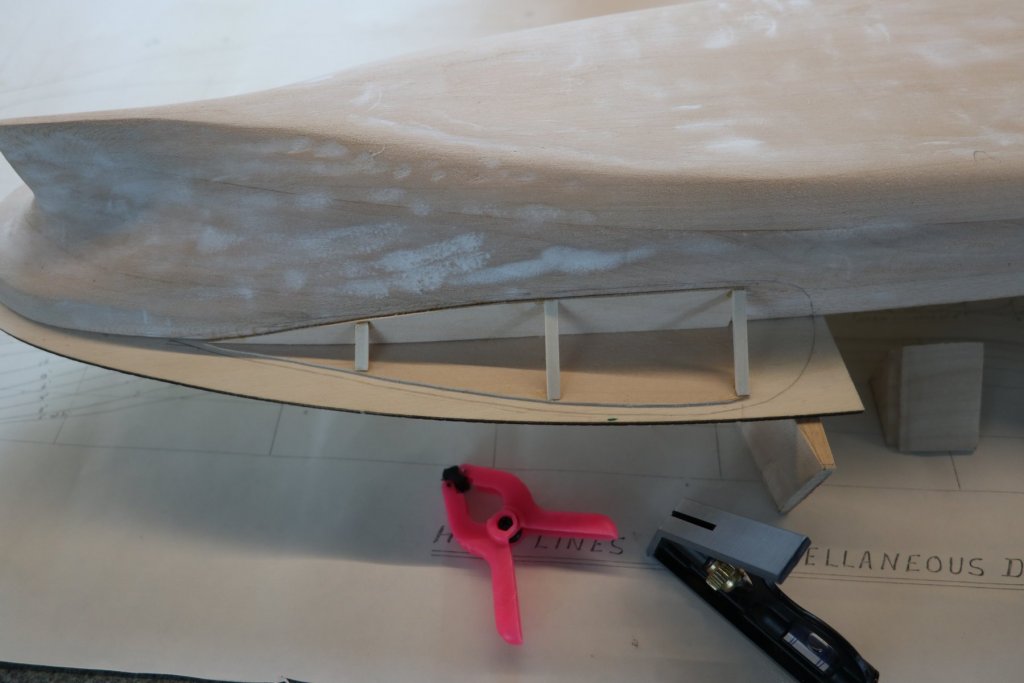
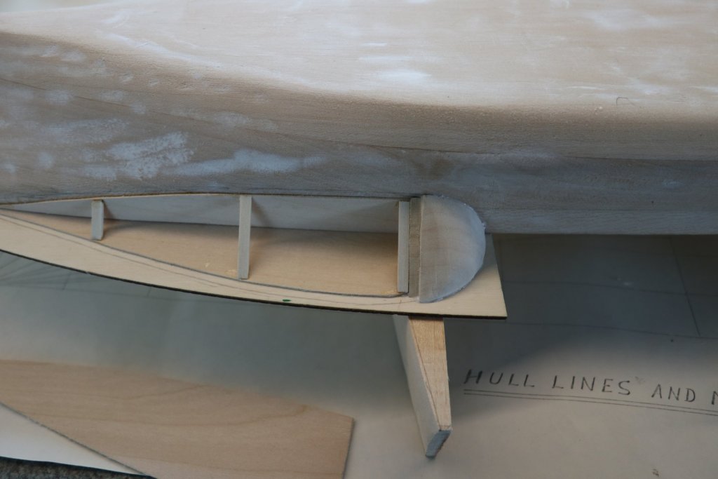
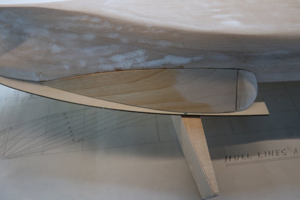
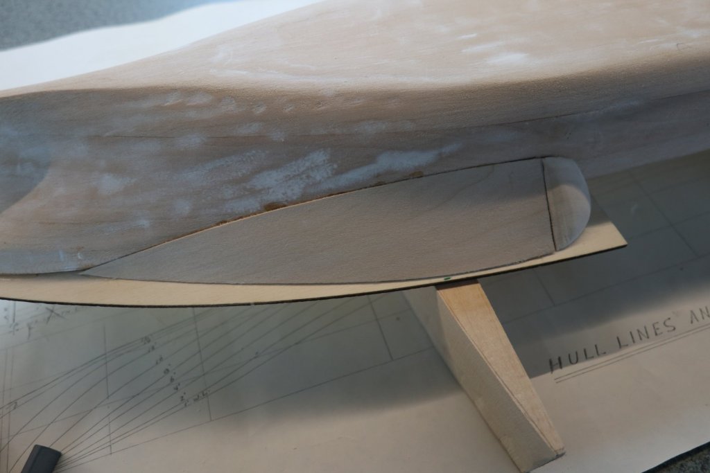
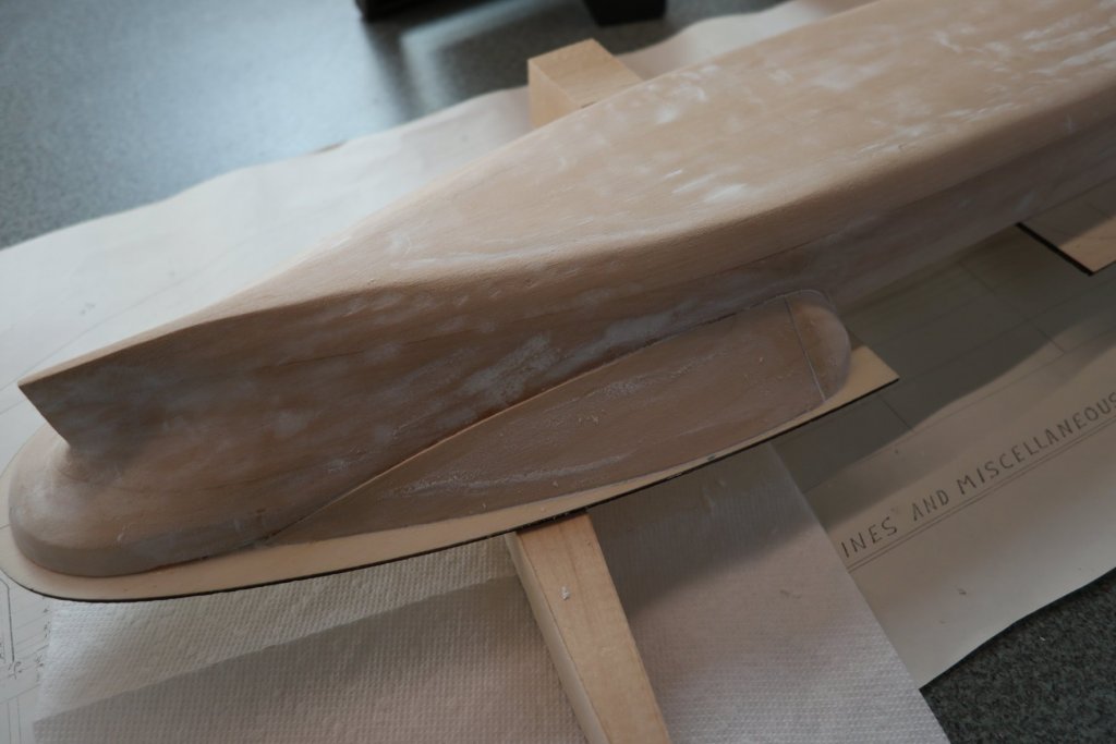
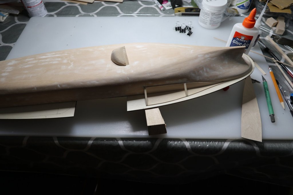
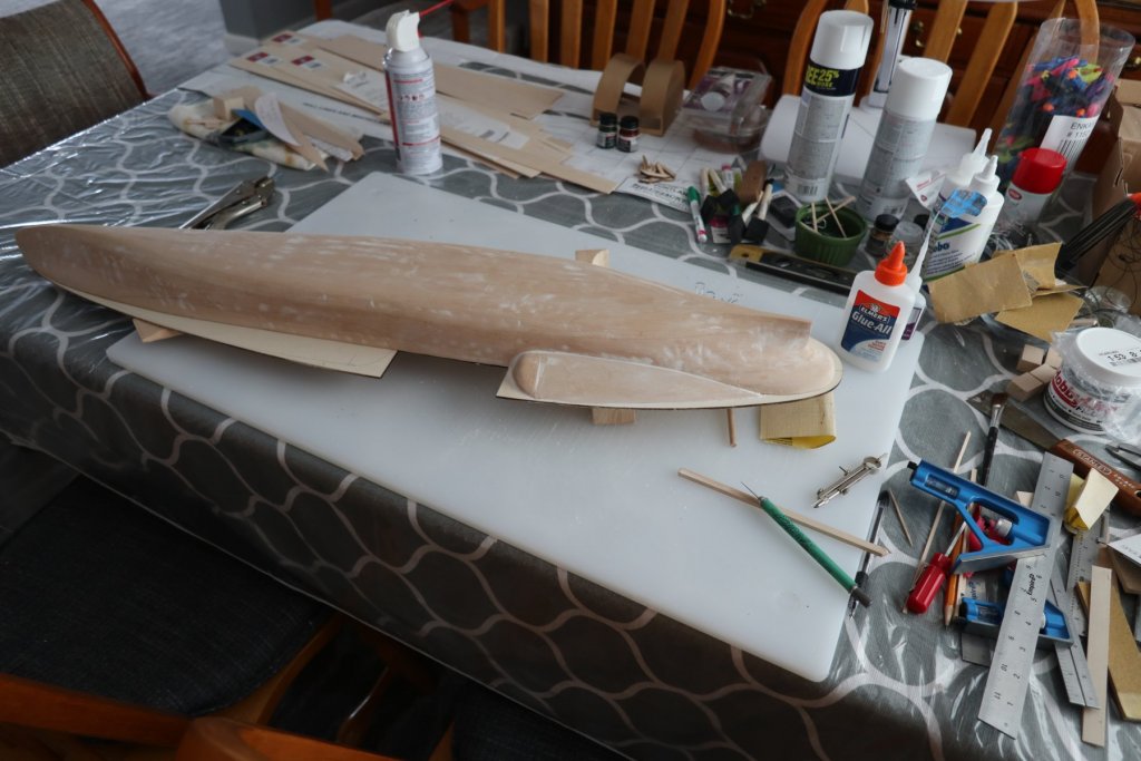
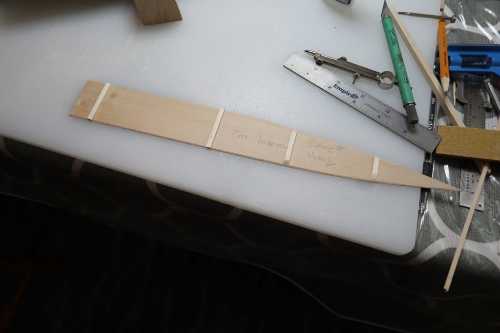
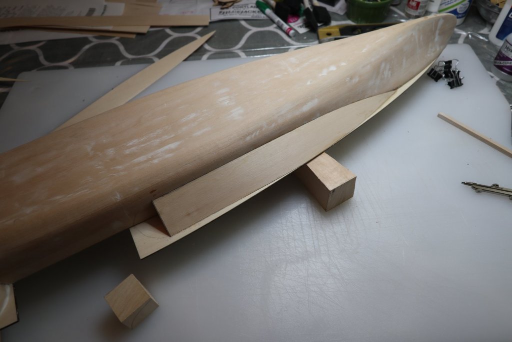
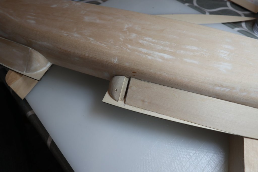
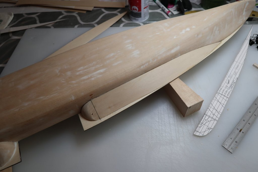
Sponsons My stepson and I got this far when he started his Portland back in 1996. At the time, the plank on frame instructions did not seem to be the best way to conquer them. I'd like to show what we did back then, then I'll show the 2019 model. In 1996, we decided to make the sponsons out of solid balsa. It actually worked out! Having stored the kit for 23 years, one of the sponsons was dented. Not bad! We only got 2 completed. That was the end of the 1996 build. I considered doing it again on the 2019 kit using basswood this time. I couldn't remember how we got the shape down so well the first time. After some consideration, I abandoned this method. I really liked John and Clarence's method described by John in his sponson post. I got everything together successfully, but didn't feel I could hold it in place to glue it down. Then I saw Dan's sponson build. He used 3 frames as a support for a one piece sponson like John's. I went one step further. Probably overkill, but It kept my brain on the right track. Using 2 sided tape, I taped the back of the plans to a 1/16th basswood sheet and cut out the sponson profiles. The stern sponson profile for under the deck was too wide. I trimmed it back so the clearance to the deck edge was the same as the plans. I cut some spare profiles out of old file folders. The additional step I took was to cut out an additional deck and hull profile out of 1/16" basswood. On the deck profile, I scribed back 3/32" to accommodate for the angle of the one piece sponson. I also cut it off where it will meet the formed rounded tip of the sponson. I glued that piece down. It's just framing. I cut out a hull profile and scribed it 5/32", 3/32 for the angle, and another 1/16" for the thickness of the other profile. Again, I cut off the rounded end where I would place the tip of the sponson. I installed 3 frame pieces. I shaped the rounded end from the basswood supplied with the kit and glued it in place. John mentioned he cut a rabbet to slip under the one piece sponson. It provides a lot of additional support and was easy to add. Thanks John! I used John's method to determine the size of the sponson. That worked perfectly. I cut out those parts. I soaked the thin end of the sponson so I could get it against the hull. I CA'd the part into place. The molds were probably overkill, but it really kept me on track. Once it dried, I started using filler. I'll sand this out and add more filler as needed. So I'm calling this "1 out of 4 done". I'll add more photos as I move through the filling/sanding, and I'll add a few photos of the remaining 3 sponsons. I'm sure it's been done successfully, but the plank on frame method does not appear to be the easiest way to go. I'd like to thank John, Clarence, and Dan for getting me where I needed to be on sponsons! Lots of filling and sanding to do, but here's the 2nd sponson. I started one of the forward sponsons today. I had made measurements per John's instructions, and cut out 2 sponsons a few weeks back. Both looked good, but I still wanted a bit more support behind them. I went a different way with this one. I glued 1/16" strips on the back of the sponson. I sanded the edges so the entire thing would sit in place correctly. I CA'd the first 3 inches, and continued until it was in place. I worked on the bull nose piece. I have plenty of filling and filing to do, but I'll do that after completing the 4th sponson. Monday 08/12 I installed the 4th sponson. I will post additional photos after the filling/filing/sanding ritual that is next.


-
Having the figures on your ship is just too cool. It looks great, and shows some serious artistry! The ship looks great so far, and thanks for sharing!
-
John, Concerning the paddle wheel boxes, I spent a while looking at the same issue. The instructions and plans are not detailed enough to figure out how long the covers should be. The new manual says the laser cut parts are 6" long. The old manual says to cut out 4" pieces for the covers. So I looked at the photos. In the new manual, photo 6 on page 24 shows the boxes in place with 5 braces, none in the bottom position, and no covers installed. Photo 11 on page 26 shows 3 braces, with two on the bottom. Also in photo 11 it shows the covers cut off above the bottom brace. Looking at it all, I don't think it would matter either way! At some point, it will all be covered up. Because I'm still not positive which direction is best, I saved the cut off parts in case I need to reattach them. I'd also like to hear what other builders did. By the end of this build log we should have a good idea which way works best!
-
Thanks John, I'll prime my paddle wheels first just in case. Got the templates ready for the sponsons and will be doing that soon! Getting ready to paint the paddle wheel boxes gold also. You have been a great wealth of information for me, and I appreciate it. Part information, part support, part "just do it", you have been instrumental in my process though this and I appreciate it!