

Jolley Roger
-
Posts
258 -
Joined
-
Last visited
Reputation Activity
-

 Jolley Roger got a reaction from Old Collingwood in J-47GE-27 Turbojet drawn in Solidworks then eventually 3D printed at 1/32nd scale...
I can smell Jet-A1 just by looking at that picture🙂
-
 Jolley Roger reacted to Egilman in J-47GE-27 Turbojet drawn in Solidworks then eventually 3D printed at 1/32nd scale...
Thank you for all the likes brothers... This was my first attempt to build this... Not good....
I've ordered better materials and will take another shot at it after they arrive, I've also ordered a Chopper II, going to be much easier to cut accurate parts with it than by eye....
This is a lot more technical than I though it was going to be....
EG
-
Jolley Roger got a reaction from Old Collingwood in J-47GE-27 Turbojet drawn in Solidworks then eventually 3D printed at 1/32nd scale...
Hi Egilman,
Your dolly sure looks the part! Is there any reason why you are not printing it instead of scratching it? Just curious as i'm no expert on 3d printing.
One other thing, as per pic below, I notice there is a 'plate' between the compressor section and the combustion chambers, assume it was to mount the engine correctly in the fuselage?
-
 Jolley Roger reacted to Egilman in J-47GE-27 Turbojet drawn in Solidworks then eventually 3D printed at 1/32nd scale...
Thank you Roger! I was trying to make it look real....
I'm not printing it cause it is nothing but a mass of plates and tubes and styrene is stronger and more forgiving than resin... (and in some ways easier to work with) Resin is very brittle when cured, Plastic is frustration safer in this application...
THANK YOU FOR THAT PIC!!! It's one I didn't have and confirmed one of my guesses, the location of the rear wheels in relation to the cross bar... I guessed correctly...
That panel you are pointing out is a bolted on firewall, it is part of the airplane and will be removed to be installed on the replacement engine... It extends the engine's firewall to the outer frames of the airplane....
Swapping one of these was just like swapping an engine in a car, some parts stay with the vehicle and some go with the powerplant...
-
Jolley Roger reacted to Egilman in J-47GE-27 Turbojet drawn in Solidworks then eventually 3D printed at 1/32nd scale...
Short update my friends...
Steering yoke starts out as a rod attached to a plate......
We then add some legs...
And then the drawbar straps...
That makes a steering yoke... pretty simple wasn't it...
Tomorrow, once this cures well, paint and final assembly....
Onwards...
{psst}.. I built the drawbar as well only three pieces so it didn't take long...
-
 Jolley Roger got a reaction from Canute in J-47GE-27 Turbojet drawn in Solidworks then eventually 3D printed at 1/32nd scale...
Hi Egilman,
Your dolly sure looks the part! Is there any reason why you are not printing it instead of scratching it? Just curious as i'm no expert on 3d printing.
One other thing, as per pic below, I notice there is a 'plate' between the compressor section and the combustion chambers, assume it was to mount the engine correctly in the fuselage?
-
Jolley Roger reacted to Egilman in J-47GE-27 Turbojet drawn in Solidworks then eventually 3D printed at 1/32nd scale...
Well, I was intending to have an update showing a completed steering yoke... Unfortunately, I found that I didn't have the right materials to build this in scale... So, I redesigned it to use the materials I have on hand... .020 & .010 Sheet Styrene... This Dolly was built using 1/2" & 1/4" plate steel and 4" tube... 1/2" in scale is 1/64" or .015"... Yes, Evergreen makes .015 sheet plastic I just don't have any and no one stocks it around here... .020 approximates 5/8ths inch and .010 approximates 5/16ths inch...
So I rebuilt it in 5/8ths & 5/16ths steel... I don't think anyone is going to notice the difference...
I also added the bump stop at the rear and the accessories box at the front to make it complete....
With the engine at 5/8th steel...
So I'm ready to start the steering yoke now...
A you can see it's a rather simple affair, mostly flat plates...
So lets see if this can be built...
Onwards....
EG
-
Jolley Roger reacted to Egilman in J-47GE-27 Turbojet drawn in Solidworks then eventually 3D printed at 1/32nd scale...
Another short update, putting hubs in the wheels...
Using the same process to build up the tires, you build up the hubs using 1/4" & 3/16ths" tube, then cut them off at 1/3rd the length of the tires...
Now the secret to this is you don't clean the edges, you leave the rough sawn edge for the next step..
Insert one of the hubs into one of the tires, the rough edges don't stop it from going into the tire and provides a bit of friction to hold the hub in place...
Flip it over and push the hub down a bit, just enough to create a relief from the hub to the tire, checking on the back side that there is a similar relief, then touch it with a bit of plastic cement to lock it in place...
Repeat for the others and your done, ready for fill and paint...
Now that wasn't too hard....
Next up the steering head....
Onwards..
-
Jolley Roger reacted to Egilman in J-47GE-27 Turbojet drawn in Solidworks then eventually 3D printed at 1/32nd scale...
Ok Brothers, Finally! back to hacking some plastic....
One M-2 Transportations Dolly for a J-47GE-27....
Now in 1/32nd scale that 4" tube frame measures up to 1/8th inch.... the 12" tires measure 3/8ths inch and the 1/2 inch plate measures 1/64th inch.... so I have to figure out a way to represent it with real world materials...
We start with the wheels using evergreen styrene tubes....
The outer tube is 3/8ths, the inner tube is 1/8th the sequence is 3/8ths, 5/16ths, 1/4, 3/16ths to 1/8th with a 1/16th brass rod to serve as the axel.... The first step is the three outer tubes to make the tires... Now I didn't have any 5/16ths tube for the first step so what I did was make some to fit...
taking a section of 3/8ths, we cut a chunk out of the sidewall....
We then use a file to smooth and enlarge the gap and make them parallel...
You keep at this until the gap is wide enough so when pinched together they will slide into the 3/8th tube...
This was a tight press fit.. The wall thickness of the tubes is 1/32nd inch representing 1" in real life so each tube is a 2" step down, three steps down and your looking at a scale 6" sidewall for a 6" hub.... When glued together and cut to length, three 12" tires in 1/32nd scale....
Next up, the hubs.....
-
Jolley Roger reacted to Egilman in J-47GE-27 Turbojet drawn in Solidworks then eventually 3D printed at 1/32nd scale...
Update...
Well, the Rear Mounts are done... I loaded the rest of the compressor to check fit.... (and it turned yellow as well)
But the design of the Transport Dolly is complete....
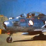
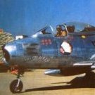
Lets see how she stacks up against the real thing, (pic taken at Suwon Korea '52or 3'ish)
A bit overexposed... {chuckle} And below...
....the mated assembly in SW......
I think I've got it, now to figure out how to build it....
Anyway, Moving forward, a bit slow but still making progress...
EG
-
Jolley Roger reacted to Egilman in J-47GE-27 Turbojet drawn in Solidworks then eventually 3D printed at 1/32nd scale...
Short update....
Forward Mounts complete...
The front compressor frame took the color of the frame when it was imported... Working on the Aft Mounts now... once those are done I'll be figuring out how to model it...
Onwards....
-
Jolley Roger reacted to Egilman in J-47GE-27 Turbojet drawn in Solidworks then eventually 3D printed at 1/32nd scale...
Ok continuing on with the plan, The engine needs something to sit on when displayed next to the aircraft.... (and a note to the boat builders, the J-47 is the engine used to power the unlimited hydroplanes when the jet era started, if your doing a Miss Budweiser or a Miss Pay n Pak or an Atlas Van Lines in 1/32nd scale, this is your ticket... I got a private question on how this applies to boat and ship building... The J-47 was used in a LOT of applications boat racing was one of them)
The only drawings I have of the M-2 Transportation Dolly comes from the J-47 Tech manual...
Empty...
Loaded..
The angle brackets you see in the unloaded image are the forward mounts... In the loaded image toy see them bolted to the engine and the circular frame and serve to hold the upper portion of the frame to the engine... The aft end of the Dolly uses the engines native motor mounts, A spherical roller bearing assembly used to slide the engine into the airframe once it is lined up...
The dolly makes use of those mounts for quickly mounting to the dolly, drop the engine into the aft mount then line up the forward bolt holes with the forward frame and you can release the engine... (interesting to note that the J-47 in the F-86 only had three mounting points, two in the center of the engine on the sides at the aft compressor frame and one top mount at the forward compressor frame... Wasn't much holding it in there)
Anyway real life images....
Museum...
In the field...
The upper brackets were designed to allow the engine to be spun around it's axis for maintenance access to the various sections of the engine, but as we can easily see were seldom installed in the field.... The Dolly was used to move the engine from the removal area to the packing area for shipping to Japan for IRAN where they would be returned to the forward field once done... (a lot cheaper than shipping them all the way back to the states)
So those are the images I have to work with... With the engine intake diameter at 36.75 inches, I should be able to scale the image and take measurements...
Onwards....
EG
-
Jolley Roger reacted to Egilman in J-47GE-27 Turbojet drawn in Solidworks then eventually 3D printed at 1/32nd scale...
Just a short update in the Dolly Progress....
Now comes the most difficult part of all, figuring out the motor mounts.....
I'm not going to do the upper halves of the rings, They didn't use them in the field so I won't be using them either...
Onwards...
-
Jolley Roger got a reaction from Canute in J-47GE-27 Turbojet drawn in Solidworks then eventually 3D printed at 1/32nd scale...
I can smell Jet-A1 just by looking at that picture🙂
-
Jolley Roger reacted to Egilman in J-47GE-27 Turbojet drawn in Solidworks then eventually 3D printed at 1/32nd scale...
Another update....
SUCCESS!!!
One complete printing!
Yay team! Now I get to create the M-2 Transportation Dolly for it so I have a place to put it once assembled... This test piece is a good example for testing the Dolly...
One builds the other....
Onwards!!!
-
Jolley Roger reacted to Egilman in J-47GE-27 Turbojet drawn in Solidworks then eventually 3D printed at 1/32nd scale...
Well, she's printed, washed and dried.... And I broke her... the Turbine Housing and Exhaust Cone was too thin to handle the clearing away of the supports.. but they did print very nice...
There you go, a 1/32nd scale J-47GE-27....
This is where she broke....
I don't think I need to redesign, just be more careful when removing the supports....
Two steps forward and one step back... {chuckle}
So 3D printing will work for this scale.... As long as your careful in cleaning them.... I may have to thicken the aft end walls a bit but that is ok, I have proof of concept...
More later, right now I need some sleep....
Onwards...
EG
-
 Jolley Roger got a reaction from lmagna in J-47GE-27 Turbojet drawn in Solidworks then eventually 3D printed at 1/32nd scale...
I can smell Jet-A1 just by looking at that picture🙂
-
 Jolley Roger got a reaction from mtaylor in J-47GE-27 Turbojet drawn in Solidworks then eventually 3D printed at 1/32nd scale...
I can smell Jet-A1 just by looking at that picture🙂
-
Jolley Roger reacted to Egilman in J-47GE-27 Turbojet drawn in Solidworks then eventually 3D printed at 1/32nd scale...
Ok Brothers, the general design is done, still a lot of details to do but the basic engine components are completed.... Will be setting them up for printing tonight....
Final part is the Exhaust Cone, it comes in two parts, the casing and thrust cone and a little tail point that glues onto the end... I had to make it in two pieces to allow a hole for the resin to drain when it prints...
Front...
Rear...
And the tail piece...
All assembled, it looks like this.... (compared to a real one)
I think it fits the bill, at least it looks the part way better than the kit parts did... Anyway I'm now doing the configuration for printing the aft portions...
I'm hoping I didn't screw it up and it goes smoothly...
Update on the printing in a bit....
EG
-
Jolley Roger reacted to Egilman in J-47GE-27 Turbojet drawn in Solidworks then eventually 3D printed at 1/32nd scale...
Another update...
Turbine section complete....
Front...
And the rear... I had to do a double loft on this one to reduce the cross section area to give it a better chance of printing successfully....
And coming up, the Exhaust Cone...
Onwards brothers....
EG
-
Jolley Roger reacted to Egilman in J-47GE-27 Turbojet drawn in Solidworks then eventually 3D printed at 1/32nd scale...
Thanks Ken, the turbine section comes next, it's fairly simple basically a can with a flange on the end.... Then a tapered cone for the exhaust... It shouldn't be too much longer before I'm printing
again... Nothing inside will be seen...
Finally got the details done on the combustor assembly, cross fire tubes are in the Alcohol/Water injection rings are on and the bolts installed... it getting easier as I get closer to the end...
Making progress....
-
Jolley Roger reacted to Egilman in J-47GE-27 Turbojet drawn in Solidworks then eventually 3D printed at 1/32nd scale...
Latest update Brothers..
I spent the day tweaking the Combustion Section Design for fit and appearance, there is still one question to decide, do I print it as one piece or as nine separate pieces... I think I'm going to try one piece first and see how it goes...
Complete section...
Still lacking some of the details, tweaking it really took all day... The cans were initially 3/8th too large leaving a gap between them of only 1/4 inch, that had to be at least an inch apart to accommodate the crossfire tubes... They now are....
The Combustion Section Frame...
Making the cans a bit smaller allowed me to maintain the indexing/attachment rings on both ends, (male/female) so they are consistent on each section from front to back... But it is clear I did have to reduce the diameter of the middle section to accommodate the burner can size... This gave it a unique ribbed look once the ring holes were punched thru... So I went ahead and filleted them to eliminate all the sharp corners and it came out with that corrugated look, it works for me, reduces the resin amount and adds strength exactly where it is needed...
Back Side...
The back flange is going to remain plain, there is nothing there which will be seen aside from the bolt pattern...
Burner Cans,,
I gave them the polished steel look which is more representative of real life.... (a nice contrast to the rest of the colors)
Back Side....
Just a couple of details to add and it will be complete....
Thanks for following and all the complements... It's greatly appreciated...
More updates later...
Onwards!
EG
-
Jolley Roger got a reaction from Old Collingwood in J-47GE-27 Turbojet drawn in Solidworks then eventually 3D printed at 1/32nd scale...
Brilliant!
-
Jolley Roger got a reaction from lmagna in J-47GE-27 Turbojet drawn in Solidworks then eventually 3D printed at 1/32nd scale...
Brilliant!
-
Jolley Roger got a reaction from Canute in J-47GE-27 Turbojet drawn in Solidworks then eventually 3D printed at 1/32nd scale...
Brilliant!