smileyjon
-
Posts
32 -
Joined
-
Last visited
Content Type
Profiles
Forums
Gallery
Events
Everything posted by smileyjon
-
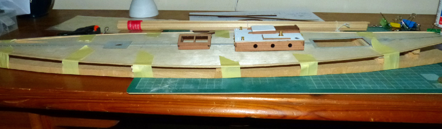
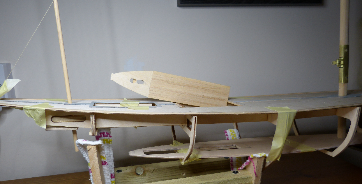
 Well it has been a while with far more thinking and planning than building . . but things have s l o w l e y progressed. Pics attached, and working from bow to stern . . the notch in the bow is to take a shaped block to offer more support for the bow top capping and a secure anchoring point for the main forestay (similar anchor point through deck for main backstay) The spare winch drum will eventually have tension springs towards the front bulkhead and will have the pull-push lines back to the winch servo for the sheets The standing rigging shroud attachments needed to be stronger (7 each side) these lead through the rail, then the decking and finally secured to side beams. The helming well at the stern will provide access to make the final connection from the steering server to the top of the rudder (pic shows the links hanging and not as they will be when connected). The floor and back wall of this well will be added at the end. So I need to install the sheet lines and tensioned pulley, then the piping for the sheet lines, the sheet lines themselves, finish the 'sailing' keel attachment bolts (and waterproofing), plank and sand the deck . . check and recheck everything, glue down the deck and glue into the hull. That's the winter sorted then ! Jon
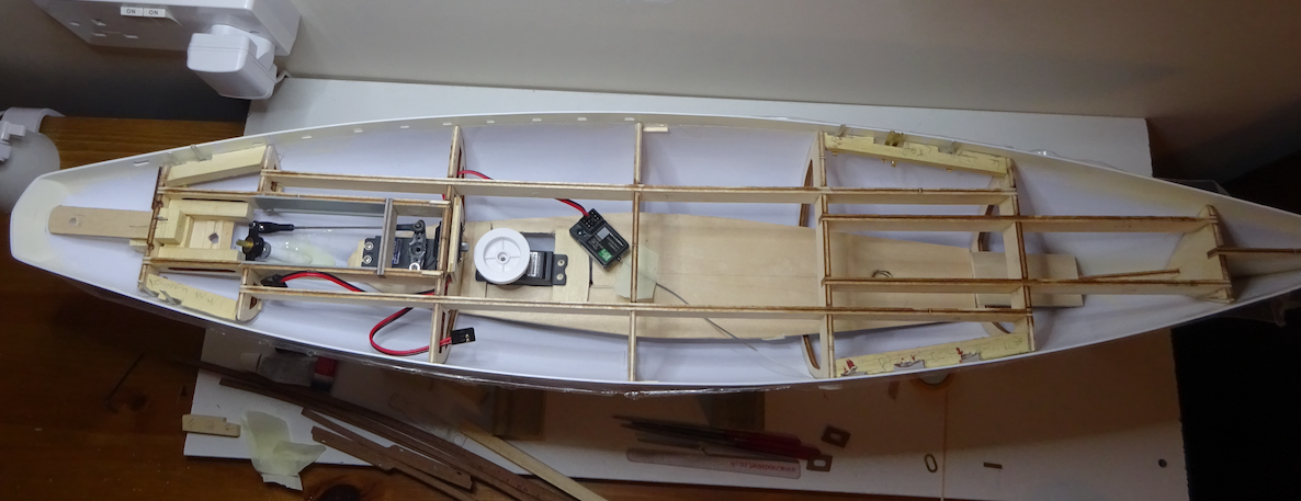
-
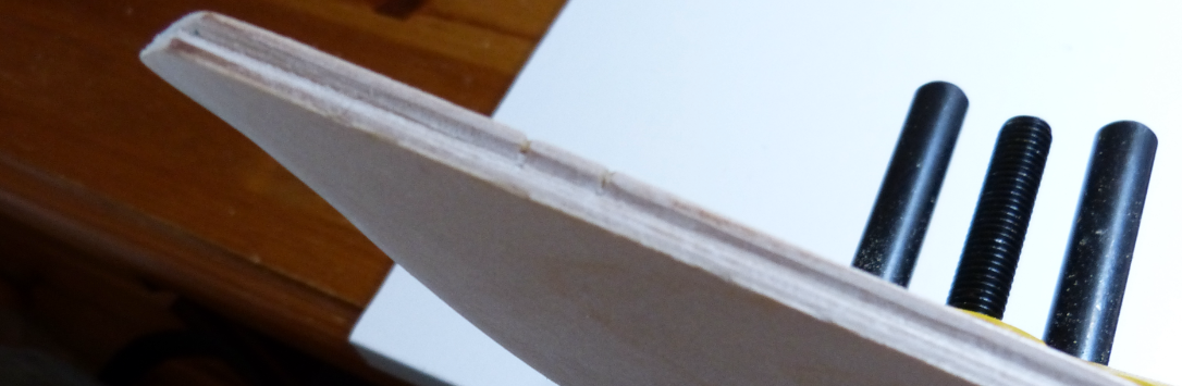
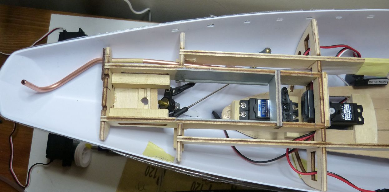
Worth a try eh . . . . . ? I bought a £13 mini pipe bender and some 4mm copper tubes with the idea of routing the below deck sheet lines to eventually line up with the winch lines A trial dry assembly of the most difficult sheet run is pictured here. Any thoughts anyone ? I've also formed a small section of timber to fit at the bow (from the frame up to the underside of the side capping) to take the strain of the main mast forstay, rather than connect it to the somewhat flimsy cap rail . . . more details later. Still working out which winch server is needed and how much travel I'd like on the 3 sheets, I've ordered a small lump of brass to 'try' and make a heel for the rudder and then assemble some of the more interesting parts The key to my plan is to get the outer hull all but ready, the internals tested (with masts) and ready, the deck planked and final test fitting . . and then all brought together . . Ha !
-
I can get them for £1 each and they are described as heavy duty ones with 150mm 'tails'
- 502 replies
-
- 1
-

-
- Quadrireme
- radio
- (and 1 more)
-
Quality build . . . I'll never build one but I'm following this !
- 502 replies
-
- 4
-
-

-
- Quadrireme
- radio
- (and 1 more)
-
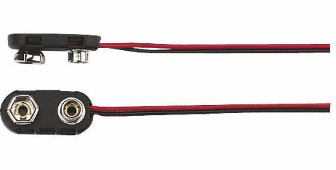
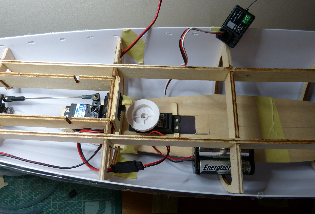
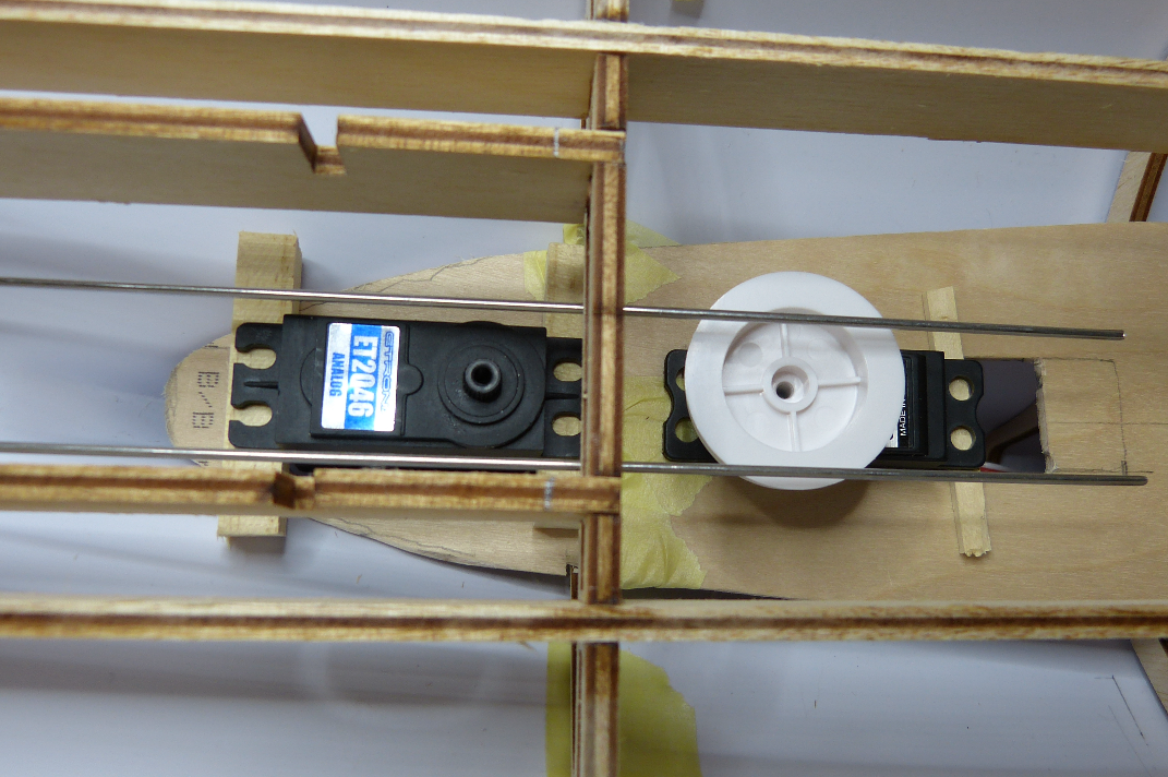
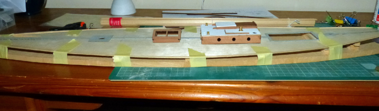
Steering mechanism and rc components positioned . . finally . . but I've still a way to go before I can begin gluing it all together and begin to create a model pond yacht. The photo shows a power lead leading aft from the on-off switch that won't be used (it's to connect to a battery charger). I'll put the battery pack in an open topped 'box' roughly where it is. The 2 servos will connect to the receiver on the port side. 2 lines will run out from the double drum winch and the 3 sheets will connect to this line. So . . has anyone ever run sheets though tubing ? getting the 2 aft sheets to the port winch line is not straightforward and they will need to go through at least 2 bends . . equally the front sheet will have to be fed back and connected (IF I HAVE THIS RIGHT ?) to the starboard winch line. I could use a wire type of thread though the tubing and connected to the winch lines . . and for show, blocks and regular rigging thread up to the booms . . . .
-
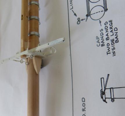
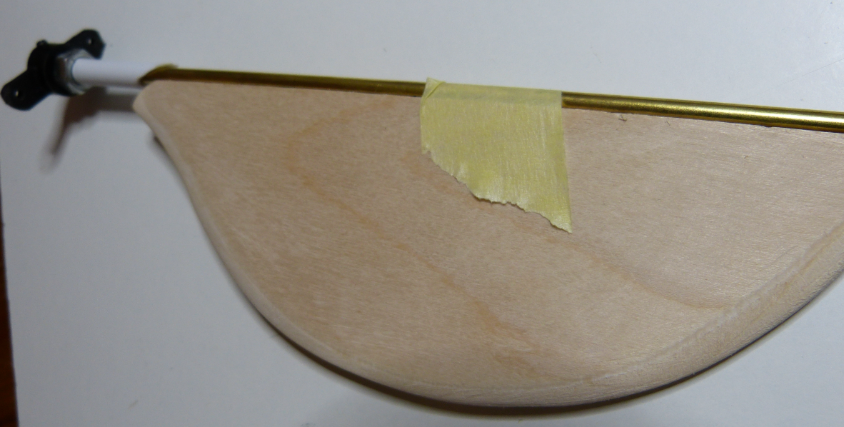
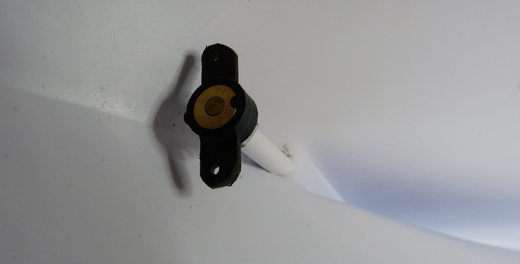
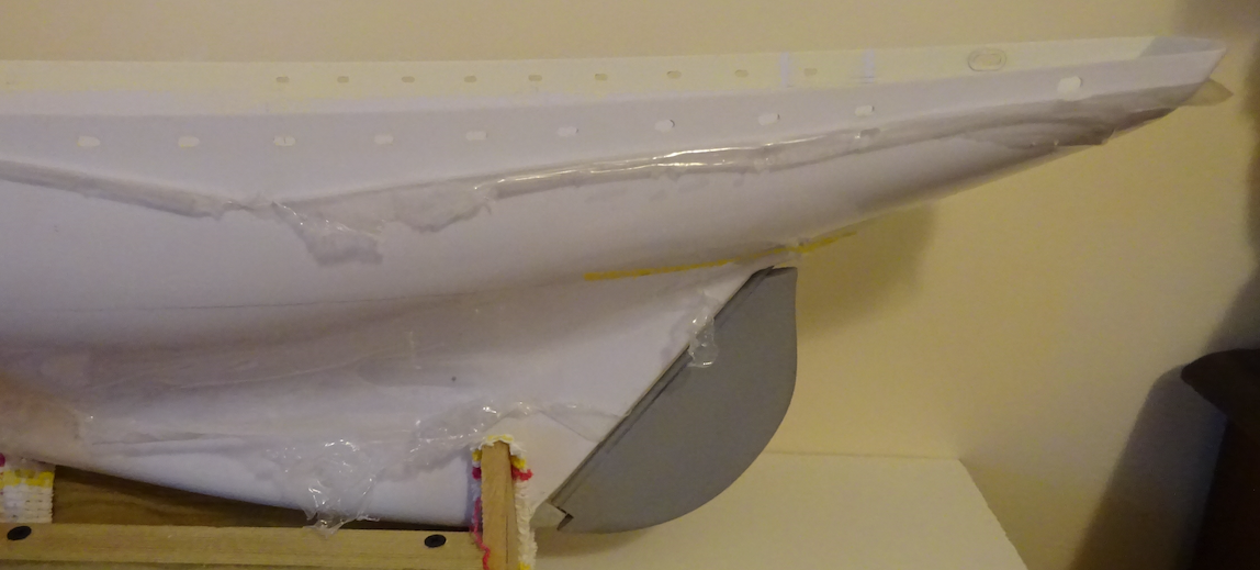
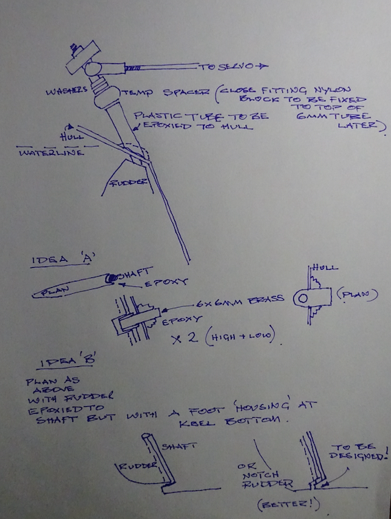
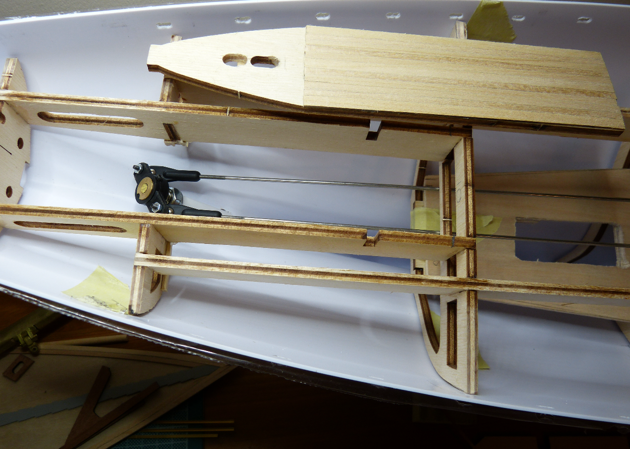
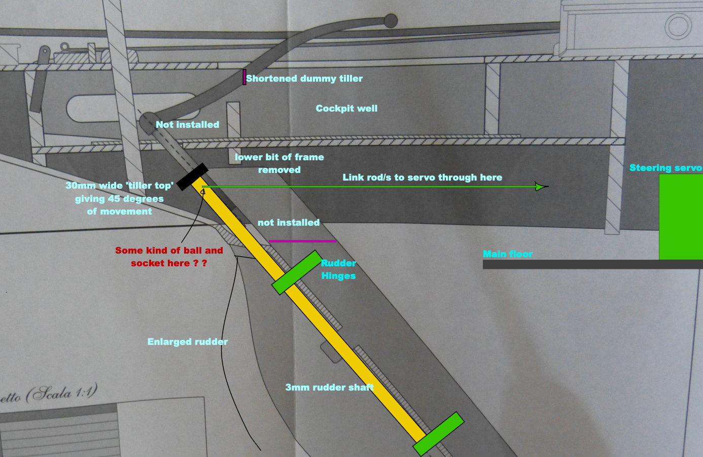
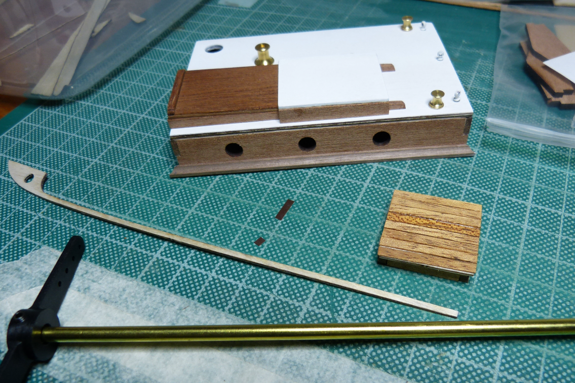
Rudder servo links under the cockpit floor have been installed and tested . . these 4 bought for £5 from a model store 1/2 a mile from my home. All I now have to do when I insert the frame assembly into the hull is drop the server ends onto the 2mm bolts from the server arm, add the nuts and a dollop of superglue as future access will be denied . . hey ho ! Back to the rudder installation then . . . I have a 3mm solid brass rod from the 'tiller' that runs down the stern to keel level (not illustrated is this rod protruding up through the the tiller held down by a frame mounted 'cap'). and the plastic sleeve perhaps should be metal. So a couple of ideas (one based on above suggestion . . thank you as always)
-
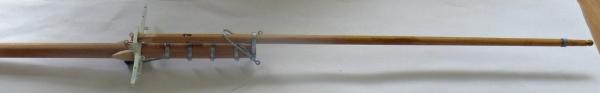
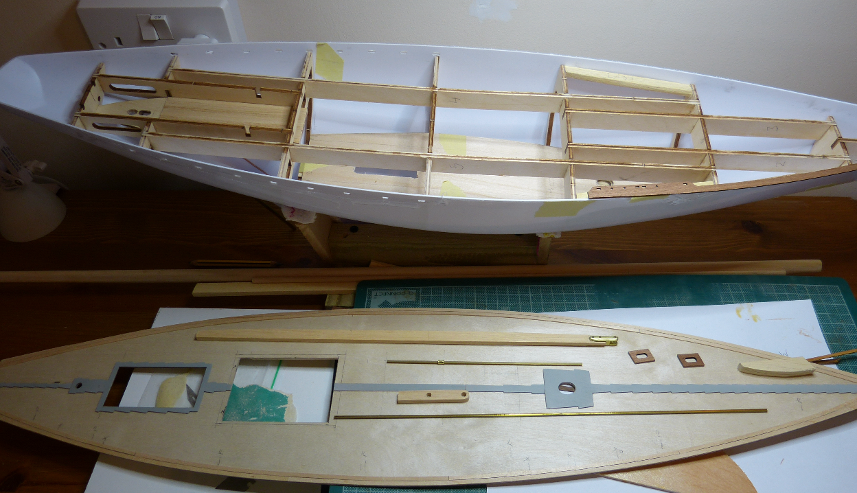
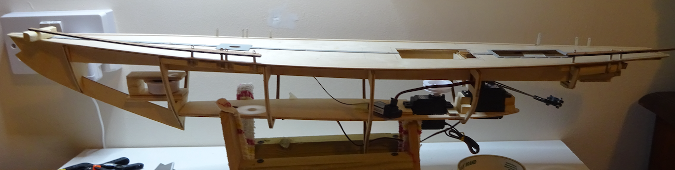
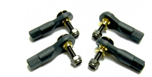
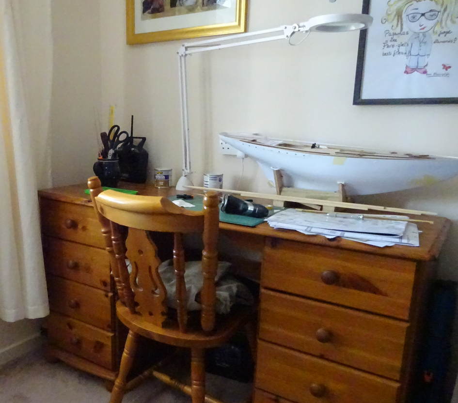
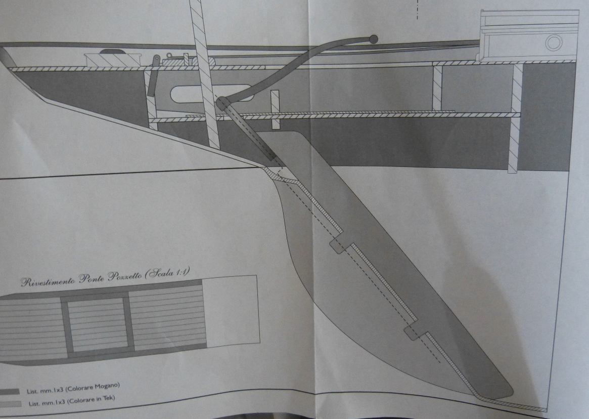
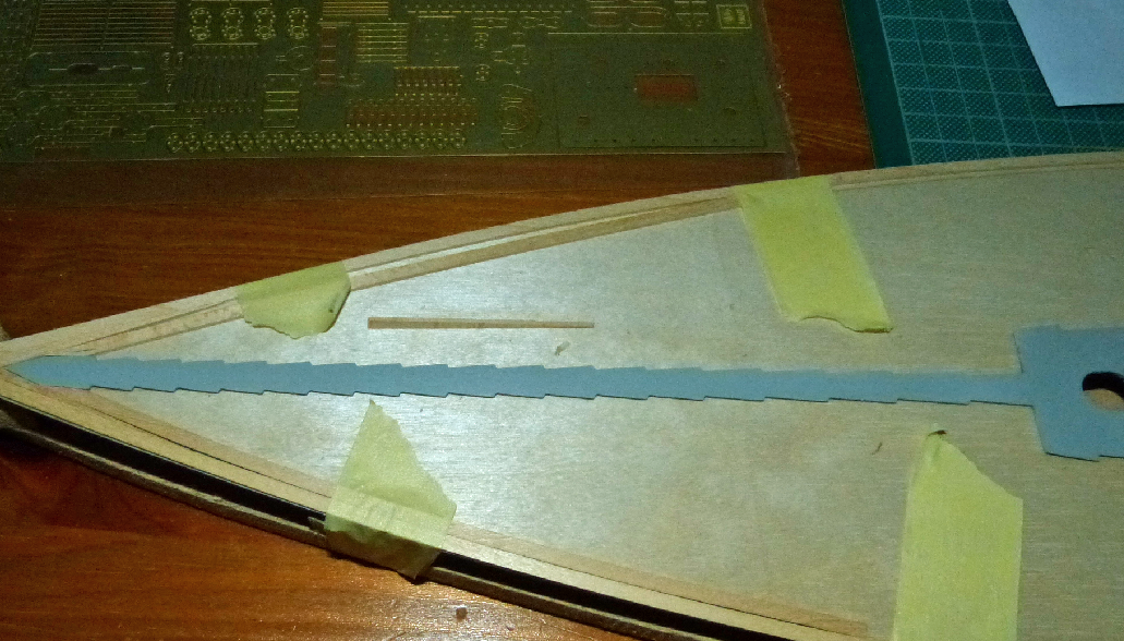
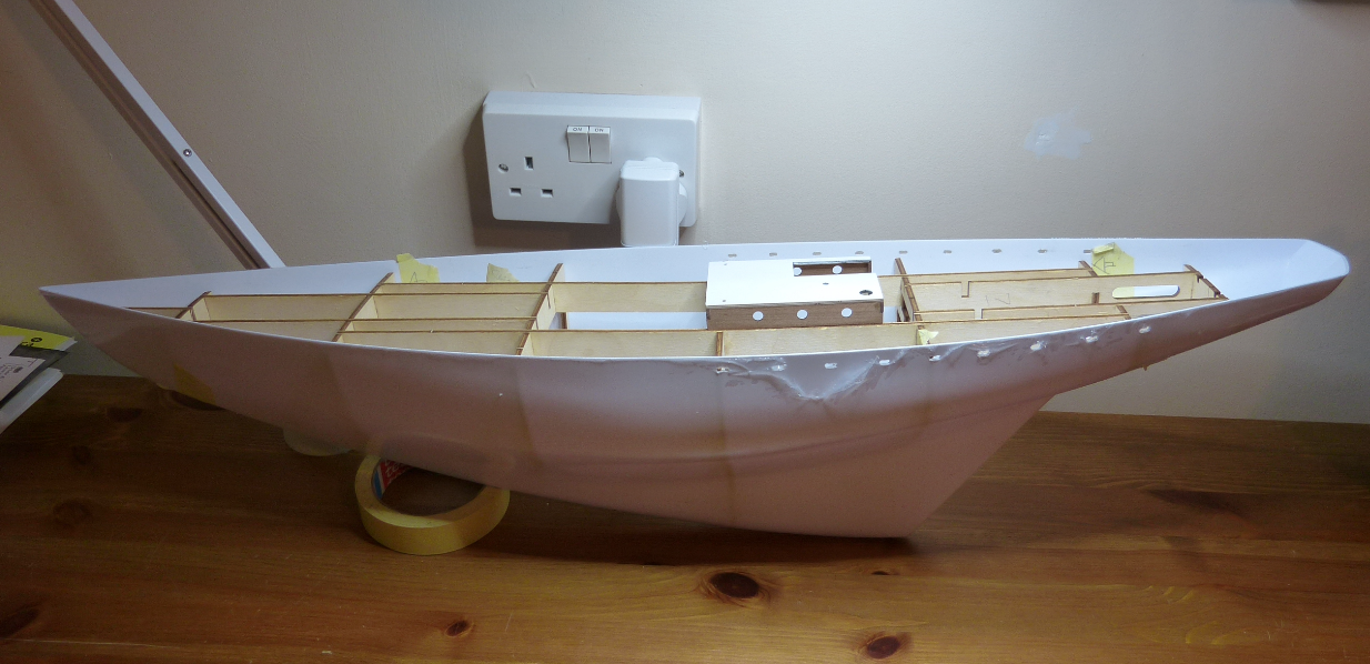
Slow progress . . much of it just thinking time . . Be careful if you build this kit as I'm finding tiny position issues with the hull framing, and should you wish to add a rudder servo . . . Latest pic of rough assembly: The cockpit floor from the kit will be cut down alongside the rear planking as the 'nib' at the end has a hole for a static rudder, and because of the steep rudder angle the linkage bar at the tip needs room to tilt as it turns. Also the hole for the mizzen foot needed moving about 2mm forward. The cockpit floor will need to be removable at some point . . and sit slightly higher to give the linkages room to twist. The 2 rectangular holes in the now extended bottom floor are for the 2 servos and the linkage will need cup and ball connections ! The standing rigging points will all need 'beefing up'. The kit says connect the deck (fully planked) to the frames and glue the whole assembly into the moulded hull . . . this now cannot be done as the rudder assembly will need to go through the stern of the hull and be connected to the servo which is in the framing . . so some tricky stages to come. Now I need to find suitable rudder hinges as most for sale are of the 'u' shaped forked kind and would look wrong if fixed to the outside of the hull.
-
I do like this idea . . model shop on Monday then ! Thank you
-
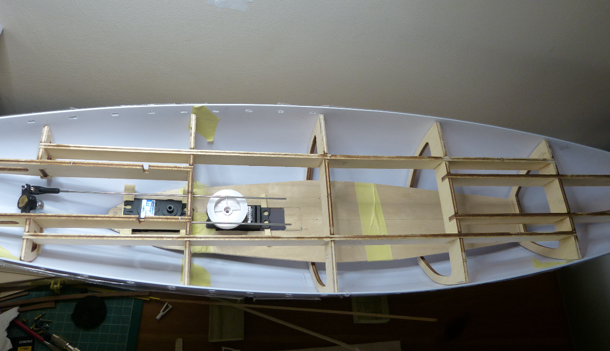
Finally . . we can begin to build ! All rough cut and taped together I've built a larger bottom floor . . slightly wider in case and extended this through the frame towards the stern to take the steering servo. Thank you Ian for the 'heads-up' on the swivel ball links, bought in the UK . . and they are perfect for overcoming the steep rudder angle. I'll order 2 more to connect the rods to the server arm. Moving the steering server back (and just under the cockpit floor) has allowed me to move the 4-turn sheet winch a couple more inches towards the stern, which in turn gives me plenty of length (up to 15 inches) to run out and back traveller wires (1 inch spool diameter x pi x 4 turns gives 12.5 inches !) Now I need to source suitable traveller cables, a small pulley for the bow end of the traveller . . probably sprung; guide tubing for the under deck sheet runs . . then space for the receiver . . and switch and little 6v battery pack which will need to be accessed . . and on and on and on . . . .
-
Bending small tubing Not sure where to post this but could anyone offer advice on bending 3 to perhaps 6mm tubing in brass, plastic or copper . . or other ideas I will have 3 sail sheets that will go through the deck of a yacht. These will need to turn through bends (at least 1 will need to go through 2 bends) which in turn to be joined to a 'traveller' line from a 4 turn winch servo. This is a one-off build so I'm trying to avoid buying equipment I will not need again. Any thoughts would be very welcome Many thanks Jon
-
Ian . . it works and probably the best fix possible . . thank you for the link to these. Limited to about 45 degrees and that'll have to do . . . but this is just a gentle pond yacht ! I've cut out the bottom of a frame and the cockpit floor may be a few mm higher but hey . .
-
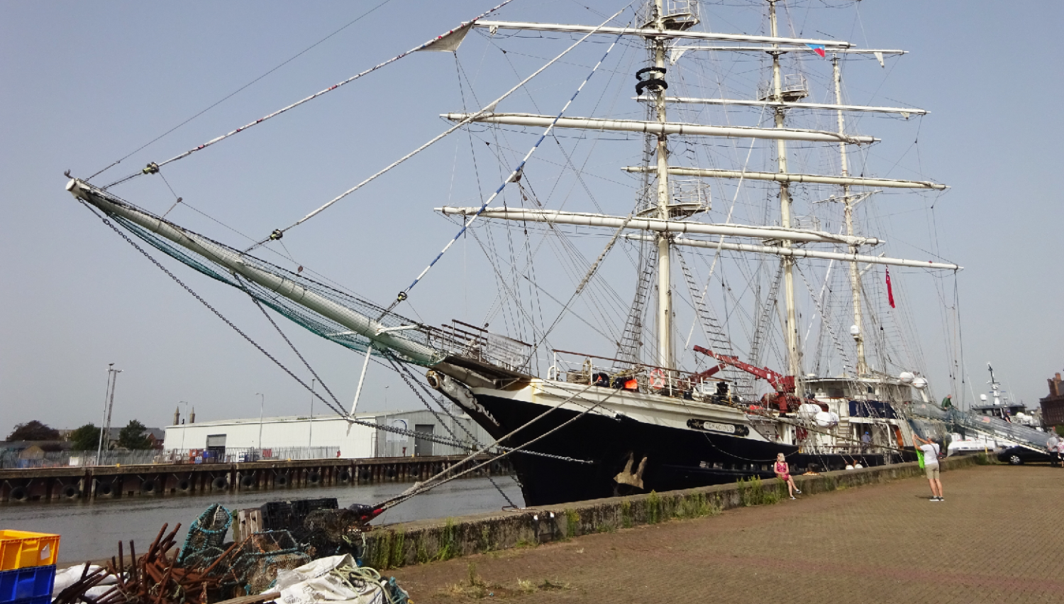
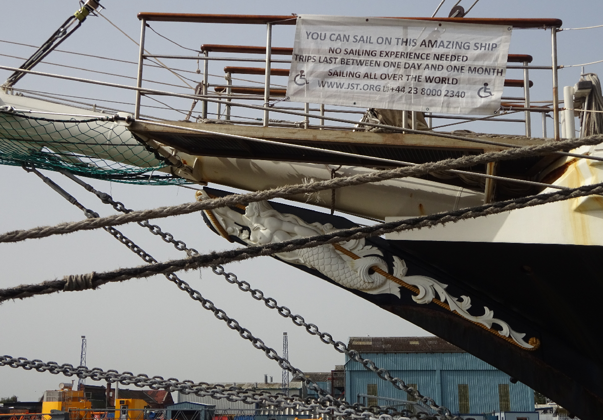
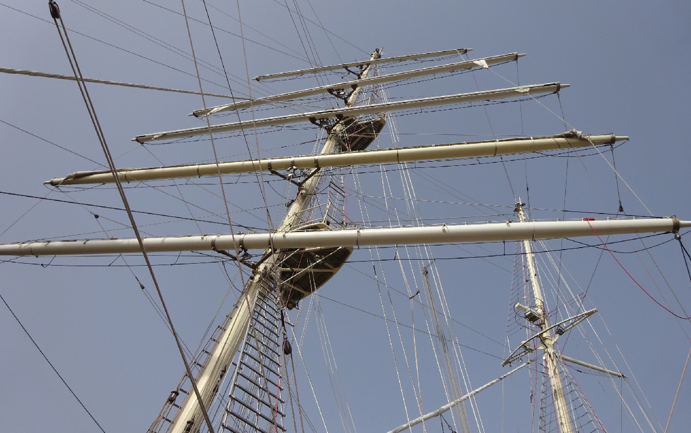
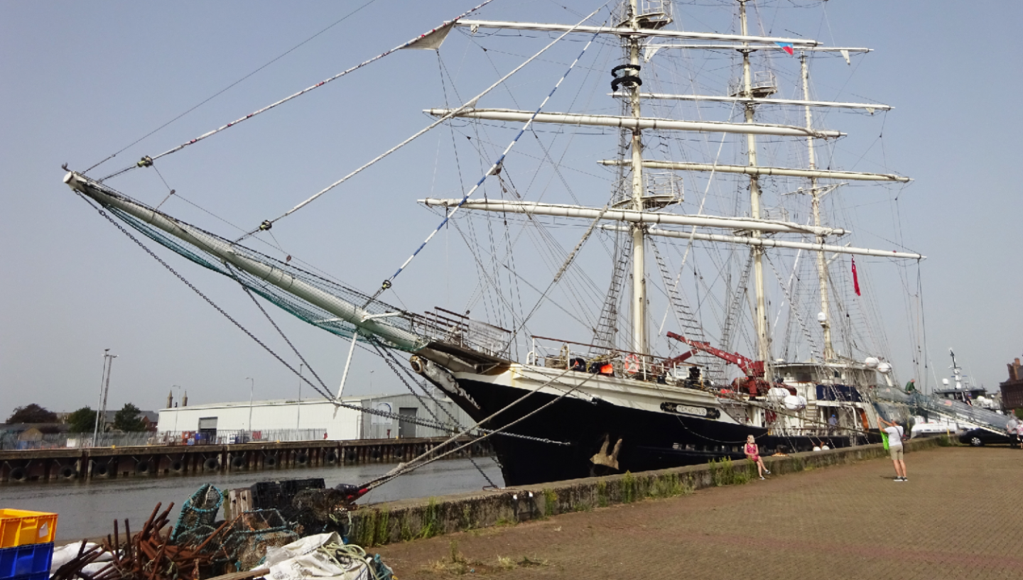
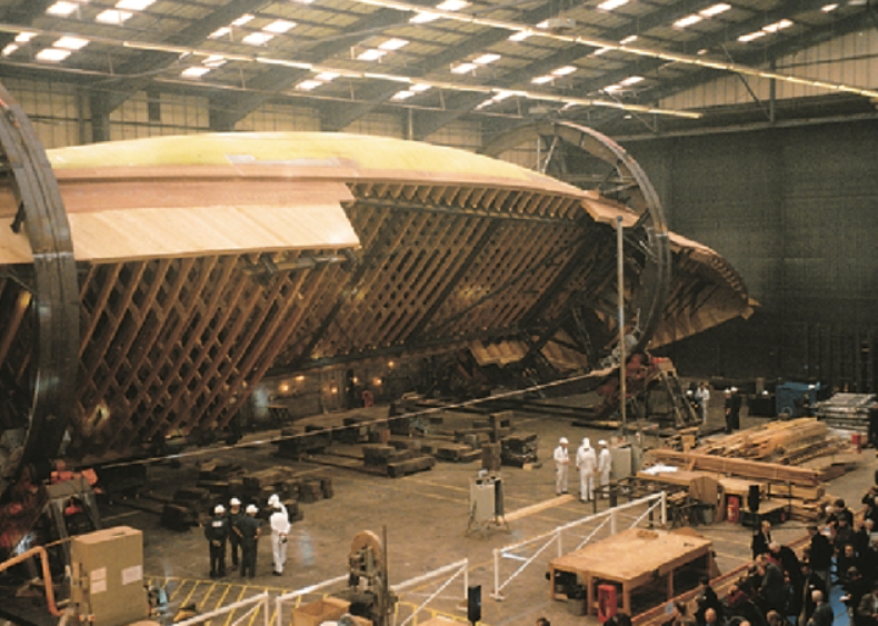
Well then . . a trip to Yarmouth to visit a 3 masted barque . . 'SV Tenacious' where we were offered a 5 day sail down to London . . . . leaving this Friday. Sadly we have several appointments next week so very very reluctantly we now plan to catch up with her in the spring when she returns from the Caribbean. She was built in Southampton (upside down I believe . . now confirmed !) by volunteers and launched 2000 . . has timber frames and planking but lots of steel and can carry 44 visitor/crew with or without disabilities. Cannot wait !
-
Many thank you's as always . . and all good ideas and well worth trying eh ! So . . I spent a while looking through your galley posts . . . my word you are up for a challenge, quite amazing and very impressive so will be following with interest. And for a future square sail build . . warship, training or full ship ? I read Eric Newbie's book and his follow up photo book on the barque Mosulu and fancied having a go at modelling this once (not r/c !) but built the trawler Maggie M and then the Model Shipways Bluenose instead. I no longer have a workshop (just an old desk area) nor much space for tools and just space for a Dremel and a clamp on vice (love your setup by the way ) . . . and I have slightly wobbly fingers and poor eyes so this build is still a challenge 😁 For now I'm going to order the ball joints and give 'em a try . . and go and spend a few hours on masts and booms . . . Again thank you so much for help and encouragement . . and ideas !!
-
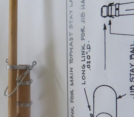
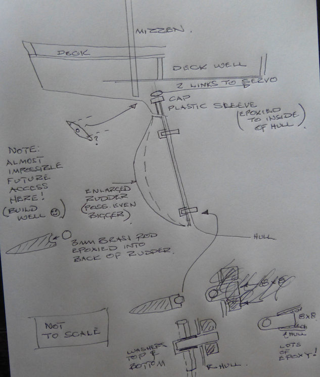
Ian . . . . sadly no pics but . . . an r/c square rigger, oh my word ! And I'll go look at the galley later . . thank you. Very slow progress . . I just want to get the basics sorted and it's kind of frustrating as I just want to get on and build the thing. A few rubbish pics Thank you as always for the ideas and info . . . Yes, I've lifted the cockpit floor a few mm and that's helped and another yes . . I'll recalc to increase the boom swing distances. Looking at my attached Corel Draw sketch . . do you know if ball and cup type connections are available anywhere to get steering links to this horridly angled rudder shaft ? ? As for future rudder access . . . not really possible so whatever I do has to be good 😄 For now I'm beefing up the below deck anchor points for the standing rigging with assorted bits of timber and I don't think the supplied rigging thread will do. That's it for now . . have a good day Jon
-
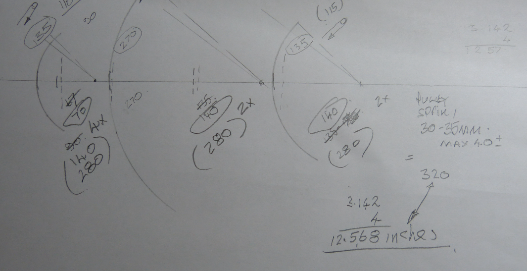
Hee hee . . I now understand what a ‘snapped sheet’ means . . thank you, and yes it is a worry and needs consideration. The darned rudder horn has become quite a problem so before implementing anything permenant I’m giving it some thinking time. I really liked it but cannot do your suggestion with the pulleys as there is but 1mm of room above the already reduced horn. Horn movement is restricted below, left and right by the hull sides and above by the decking that supports the mizzen mast heel and the cockpit floor and as the mizzen has just a couple of support shrouds and nothing fore and aft it needs to be pretty solid (see section drg) On to winches . . I’m basically going with you suggestion. I have a double-barrelled drum on the servo (line in and line out perhaps). The spool diams are 1 inch so . . . . 3.142 inches per turn gives 12.5 inches with the 4 turn servo and 6 and a bit inches with the 2 turn one. (There’s just enough room to get a clear 12.5 inch run to small pulley and spring at the bow end if I use the 4 turn servo). I have to bear in mind where the sheet lines exit to above deck due to the ‘stuff’ on the deck . . and there’s a lot of it, and rather than a reduction block below deck I could fit single blocks in an appropriate position on the jib and mizzen booms ? (note the kit build does not have a boom under the jib sail but I assume I will need one ??? and I’m only planning 1 sail at the front . . almost a genoa, a bit like yours and no flying jib I also assume that the sheets rise above deck along the centre line of said deck ? All this governs how far out the booms are allowed to go, where on the booms the sheets connect and which server is best. By my rough calc the booms would ‘play out’ to around 30-35 degrees (is this enough ?) So many questions eh . . . I’ll need to mock everything up prior to anything permanent of course ! That’s me done and sorry for asking so many questions, but before I end . . how large is your lovely yacht and do you get to sail her these days ? So . from across the water, a million thank you’s. Jon
-
Ian What a lovely reply and wonderfully useful . . and it deserves a proper answer, but not tonight as an early start for a medical appointment in the morning (getting old is rubbish sometimes !) Love your old yacht by the way. I did consider something like a J class classic but this one is going to be more display model and an occasional gentle 'pond yacht' . . we'll see eh . . . Thank you again Jon
-
Rough idea for rudder
-
Gosh, many thanks for all that Ian . . and I've clicked on 'follow' . . more thanks . . She's . . . Length: 856mm. Height: 1030mm. Width 160mm. Scale: 1:20 with the white plastic hull. A lot of internal wood as the hull is quite thin so lots of considerations and so many questions . . . . . . . . . For now I'm concentrating on the rudder and associated linkage to the servo . . (pic of kit build attached), and what a lovely angle issue to overcome especially as I need adequate support to the mizzen and I'd rather not run any 'fabricated' link rods through the 'deck well' ! Sorry no idea what 'snapped' sheet lines are, however I'm putting everything into 'trying' to get all the works below deck and improve deck access . . ha ha ! Tried test tank but not satisfactory so a dropped removable keel is planned (2 captive nuts epoxied to the inside of the model's hull). As for the winch and sheeting lines I have sleepless nights. I have both a 2 turn and 4 turn servo and a need to control 3 sails (see calc pic . . more laughs). I've worked out that the sheets need to pass through the deck along the centre line ?) . . but the servo's run for the full number of turns specified when operated and on release of the transmitter joystick immediately turn all the way back so I have no idea how you can control how much line is let out, let alone kept at any intermediate length. All or nothing it seems. And more thanks for the book suggestion Ian Best regards Jon
-
Well then, just a quickie . . .this kit and conversion to radio control is not as straightforward as I assumed, so things to consider . . Try and assemble or 'tweak' internal hull framing before gluing. The two mast step positions don't quite work when both are in position The rudder shaft on entering the hull is not in the best of places due to both framing and the cockpit area Access to any internal equipment is very important The assembled frames do not sit flush with the longitudinal timbers I have found the centre stepped strip nearest the bow doesn't quite suit the deck planking The rigging will need substantial changes . . and perhaps some under deck strengthening at the bow, shrouds etc. Take care with the 'scupper' holes in relation to deck levels I have done a very rough tank test . . too much ballast lowers the waterline . . too little reduces stability Control of all 4 sails will be complex More updates and pics soon !
-
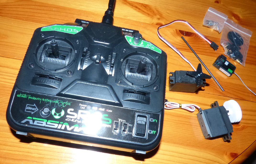
Well then . . it has begun (more details posted on another forum . . ) I've bought some r/c bits (2 channel transmitter and receiver, 4 turn winch servo and steering servo) and yet to work out what goes where let alone test things ! I'm building the deck basics on a jig that matches the frame profile and 'when' I work out how the 3 sheets are best installed I'll fit all the r/c, lines and other stuff into the framework . . then fit the framing into the hull, then add the deck and finish all the other stuff. This may change as there is so many other considerations (this is gonna be a long build) . . stronger chainplates, different rigging layout, lead sub-keel and dozens of other bits Laugh ! There are a few minor issues already . . Pics of the current mess . . . temporary jig idea, strange lecci bits, fiddling with planking as the deck length was a couple of mm out (side planking unglued in pic)
-
My second attempt at building from a kit . . this time the Amati Dorade and I'm going to try my hand at adapting it to a basic radio control for very very occasional gentle pond sailing, so . . Here we go then . . A few years ago at the ripe old age of 70, I bought Model Shipways Bluenose. A real challenge . . totally amazing drawings of the original but a lot of scratch building. (pic 1 attached and build on another forum). This kit comes with Amati's own set of drawings, lots of shiny brass, sail cloth, threads, sheets and bundles of wood. So . . internal framing part glued but not fitted, 'scuppers' rough formed, main cabin started and planked hatch under trial . . . As I've never built anything for R/C I am on a very big learning curve . . so watch this space . . at least for a laugh !
-
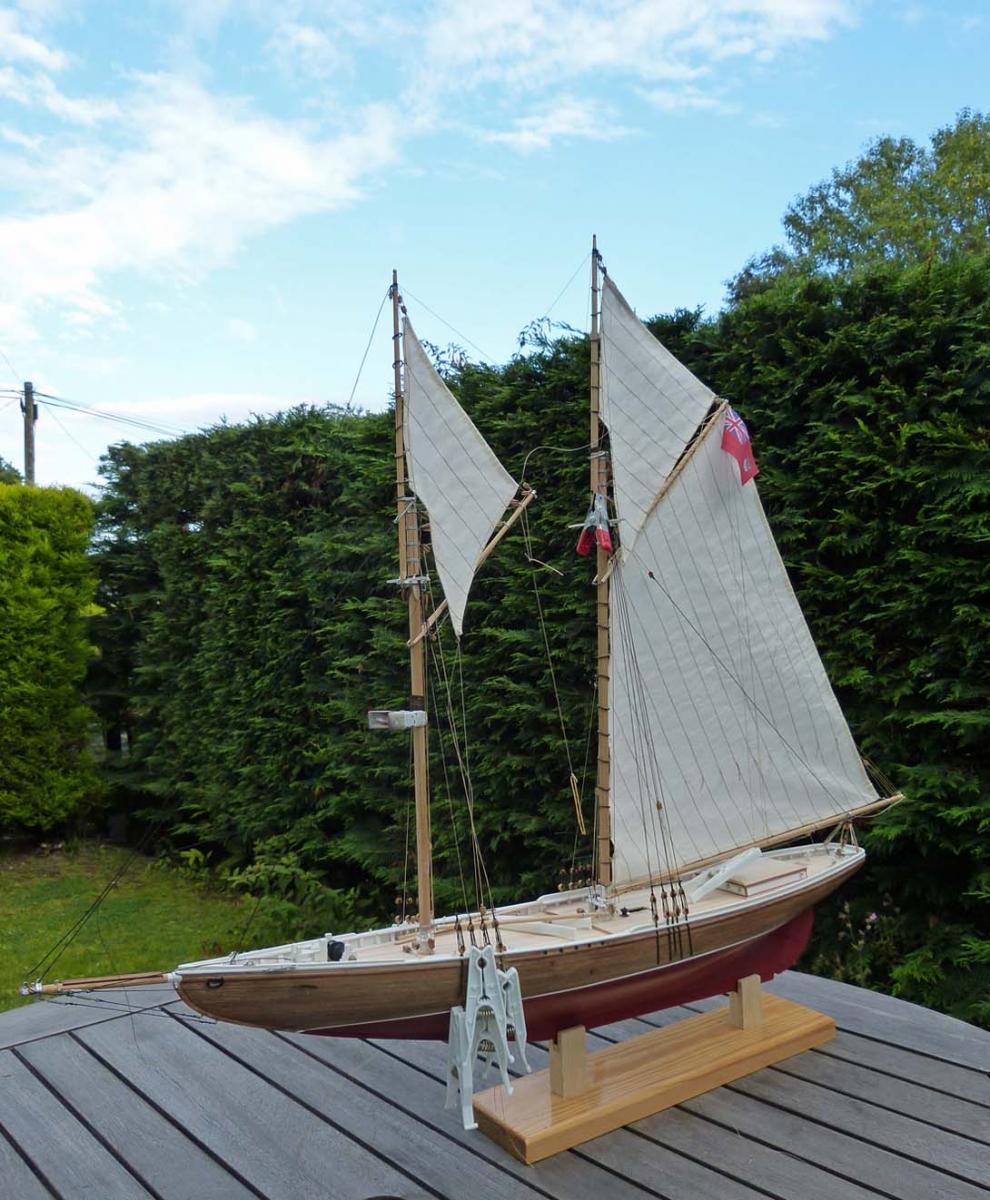
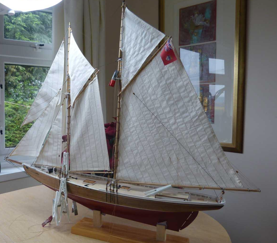
Almost there . . . 5 sails and lots of loose ends !

-
The Billings kits are very poor (sadly) compared with other makes. I had problems with this Billings 40 years ago and their issues are still the same. They just haven't improved at all in all that time . . although this is somewhat reflected in the price. However this is looking like a stunning bit of work with attention to details. I hope you continue with it and look forward to seeing it grow. I am almost through building Bluenose by Model Shipways and have a little on this site but a full workup with details and plan extracts on Model Boat Mayhem if that helps In the meantime . . well done. Jon
-
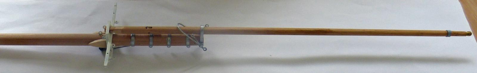
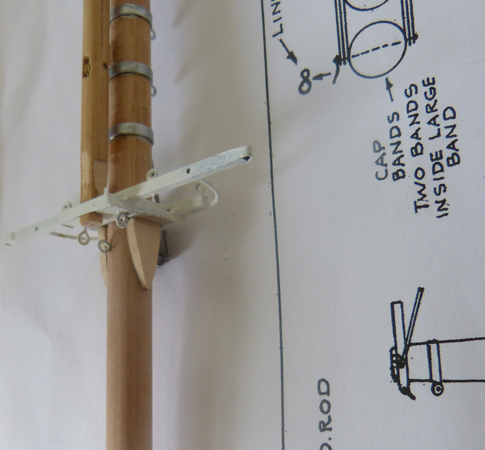
And on to the foremast . . 120 parts before I shove it down the hole in the deck and begin to step it . . . ho hum ! Work in progress obviously