HOLIDAY DONATION DRIVE - SUPPORT MSW - DO YOUR PART TO KEEP THIS GREAT FORUM GOING! (Only 24 donations so far out of 49,000 members - C'mon guys!)
×


GAW
-
Posts
183 -
Joined
-
Last visited
Content Type
Profiles
Forums
Gallery
Events
Everything posted by GAW
-
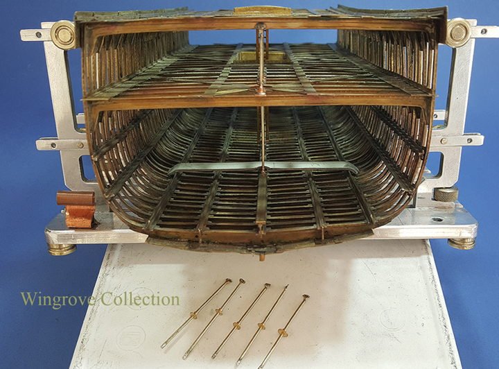
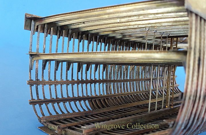
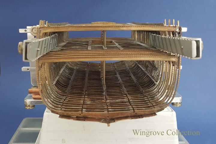
 Fig-92 -The forty centre Frames are now in place will all attachments - note Jock the riveter standing by - always useful to keep an eye on the scale of all things. The next stage is the plating of the hull.
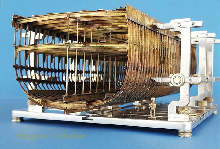
- 281 replies
-
- 17
-

-
- falls of clyde
- tanker
- (and 2 more)
-
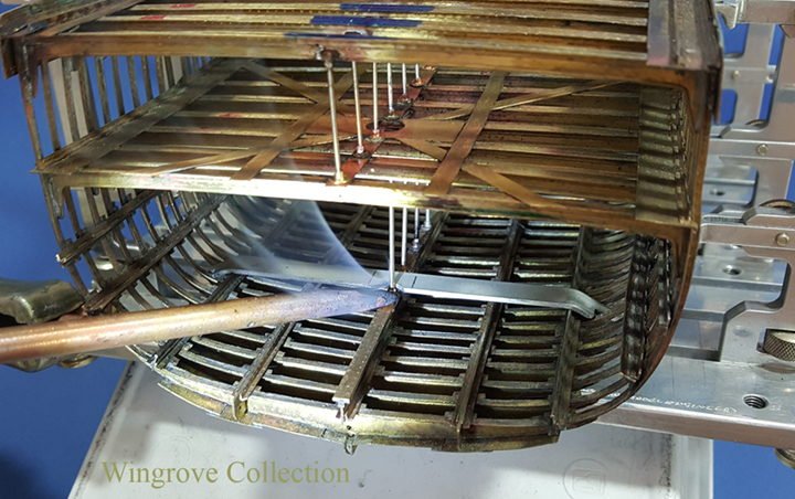
Fig-91- With the base of the Pillar correctly located in the aluminium jig fitted between the requisite two Frames, the carbon rod is again heated to complete the soldered joint.
- 281 replies
-
- 10
-
-
- falls of clyde
- tanker
- (and 2 more)
-
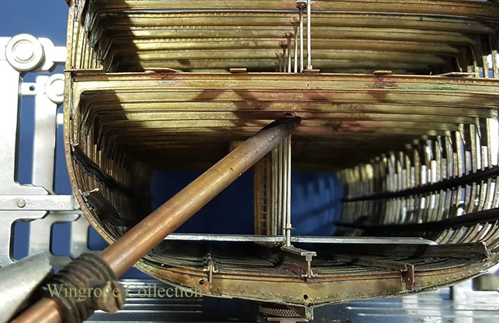
Fig-90- After fluxing the attachment point, the Pillar is first correctly located then the soft solder is melted with the carbon rod resistance soldering unit.
- 281 replies
-
- 10
-
-
- falls of clyde
- tanker
- (and 2 more)
-
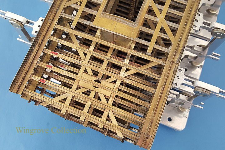
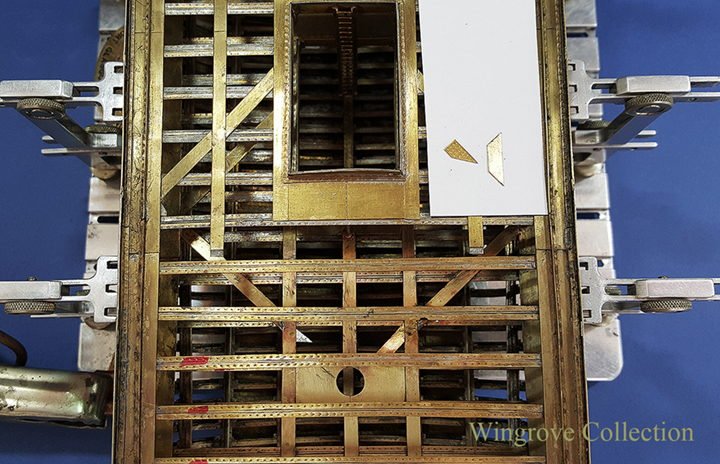
October 2017 Fig-89- With all of the Stringers in place the next task is to install the remaining Hold Beam Pillars. On the Falls of Clyde these are 3” in diameter for the tween decks and 4” in diameter for the main hold. On the model I have, as in most cases gone a little oversize for strength and convenience of available materials, and used nickel silver wire at .031” for the upper and .046” for the lower Pillars. Each Pillar has a small plate silver soldered at the top, shaped and bent to accomodate the bulb in the Bulb Iron Beams to which it is attached and supporting. Each has then had the two rivet heads formed on it at the front, and is tinned with soft solder on the back. The anchorage at the bottom is in the form of a ring and collar. The ring part being again provided with a pair pf rivet heads opposite to each other and is tinned on the underside. These are then slid onto each of the Pillars, ready for assembly into the hull. On the Tween decks this is no problem, as they are each attached to beams above and below. However locating the lower Pillars on top of the Keelson required a little jig. This consisted of an aluminium angled plate, that exactly fitted between two frames and bent to pass over the Keelson, with a small cut out above the Keelson for where the base of the Pillar is to to be attached, as with the Tween deck Pillars each of the Hold Pillars is located directly over a Frame.
- 281 replies
-
- 10
-
-
- falls of clyde
- tanker
- (and 2 more)
-
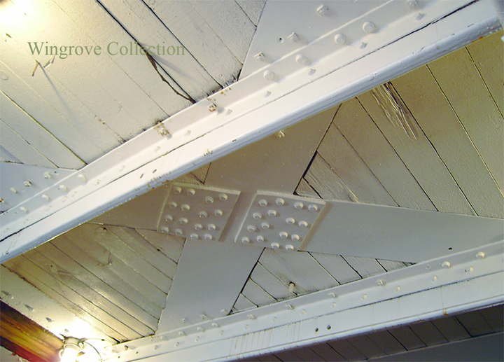
Fig-88- The Falls of Clyde main deck Stringers as seen from below. Note that although the Deck Planking sites on top of the Beams, it is recessed as it passes over the Stringers - a lot of work for the carpenters of the time.
- 281 replies
-
- 9
-
-
- falls of clyde
- tanker
- (and 2 more)
-
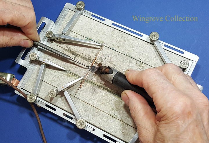
Fig-87- Heating with the carbon rod resistance soldering unit. This is switched on by a foot switch, so both hands are free to hold and manipulate the parts. The unit is also provided with a control to vary the temperature, depending on the thickness of the materials being soldered. The unit is invaluable for this type of work, where a normal soldering iron would be worst than useless, as the finish requires that no solder should be visible at the soldered joint.

- 281 replies
-
- 8
-
-
- falls of clyde
- tanker
- (and 2 more)
-
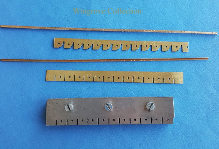
Fig-86- The Stringers have now been put into their rightful places, and where crossing a Deck Beam, have had a thin sliver of soft solder placed between them and bonded together with the aid of the resistance soldering unit - the carbon rod heating tip. To attach the riveted plates to the underside of the butting Stringers I have made use of a former dental tool, with a flat end set at an angle. Onto the flat I have placed the joining plate with the rivet heads on the under side, the top side having placed on it a tiny sliver of soft solder. With this placed under the joint, and the top heated with the carbon rod, the joint is made. Note the tiny slivers of soft solder on the white card, together with a length of the rivet headed brass strip for the jointing plates.

- 281 replies
-
- 8
-
-
- falls of clyde
- tanker
- (and 2 more)
-
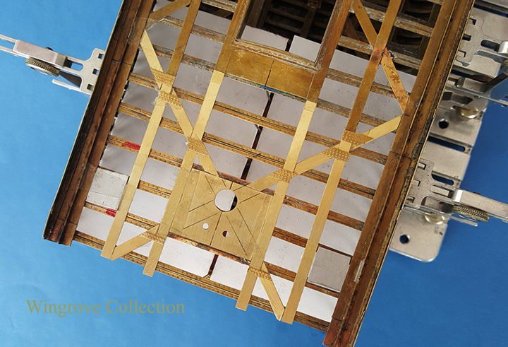
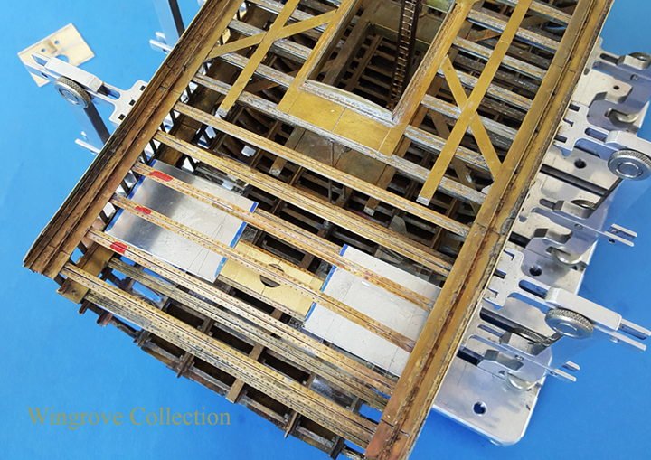
September 2017 Fig-85 - I have put white card over the tween deck Frames and Stringer, to better show the current work in progress on the main deck. Here we see assembled upside down the Stringer set for the Main Deck, and the riveted plates that hold it all together. Where Stringers pass over a Deck Beam, they are riveted to it. Where they butt up against another Stringer crossing it’s path, they are joined together with riveted plates on the underside.
- 281 replies
-
- 6
-
-
- falls of clyde
- tanker
- (and 2 more)
-
For those who found the special tools that I created for this project of interest - shown in the early stages - than you may also find of interest where the original cam design came from that was used in several of them. If so check out this months (August) contribution to my web site, < www.wworkshop.net > under ‘News and Comments’ & ‘Current Project’ to reveal all.
- 281 replies
-
- 3
-
-
- falls of clyde
- tanker
- (and 2 more)
-
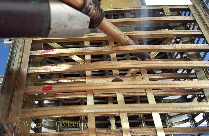
Fig-83 - The resistance soldering unit, carbon rod being used to heat one of the many stringer joints on the tween deck. A paper tube wrapped around the carbon rod was found very effective in preventing unwanted contact between the carbon rod the main deck beams.
- 281 replies
-
- 6
-
-
- falls of clyde
- tanker
- (and 2 more)
-
Fig-82 - The tween deck cross stringers cut and placed ready for soldering to the deck beams, a tiny sliver of soft solder being placed under each, between the beam and stringer for the purpose. On the white card can be seen two of the many short sections of cut plate, provided with rivet heads on one side, and tinned with soft solder on the other. These are used where ever the stringers meet to rivet them together. Note that there are not only cross stringers, but longitudinal stringers at the Bulwarks, plus two others running the full length of the hull on the tween deck, that join together the deck beams. Where ever stingers meet, they are butt jointed together, with riveted plates on the underside. On the main deck there are four of these longitudinal stringers riveted to the main deck beams running down the centre.
- 281 replies
-
- 7
-
-
- falls of clyde
- tanker
- (and 2 more)
-
Aug 2017 Fig-81 - Here we see the split plates from the tween deck of the Falls of Clyde, although this is actually the underside of the main deck where the Mizzen Mast passes through. The plates rest on the beams and are riveted to them. Note the cross Stringers that also cross the deck beams and are riveted to them also, but are butted up to the Mast plates and provided with plates on the underside to join all the parts together.
- 281 replies
-
- 4
-
-
- falls of clyde
- tanker
- (and 2 more)
-
Not yet Druxey, but at 83 this year, I am well on the way - and it is my aim - always good to have an aim in life.
- 281 replies
-
- 7
-
-
- falls of clyde
- tanker
- (and 2 more)
-
Fig- 80 - We move now to the deck Stringers and plating. As can be seen the centre 20 Frames have already been linked together with the cross Stingers, so we are dealing with just the Stringers for the 10 Frames at each end. In this way one can see what is being done, and how it is at the same time. Here we see the two plates - actually one with an engraved line across and a hole in the centre - that forms the area where the Main Mast passes through the tween deck. Again aluminium plates are used to exactly locate the brass plate for soft soldering to the Deck beams. In all of my writings, be it on the car miniatures or the ships, my aim is not to show how to build this or that subject, but to show the techniques that can be used to build any subject, hence moving along a seemingly half built model, rather than going from A to Z, which would mean a great deal of rapidity in the writing.
- 281 replies
-
- 16
-
-
- falls of clyde
- tanker
- (and 2 more)
-
Fig- 79 - The Hull section with all of the longitudinal members in place. Here we can see the newly fitted side Stringers, the 4 rivet heads and the additional bracket at each junction of Frame and Stringer. Having viewed it again now, I can see that I forgot to remove the corners of each of those brackets, however with the plating in place, these are all but invisible, one can forever improves one's work. These are the brackets that can be seen in Fig-40, in front of Jock the Riveter, together with the Guillotine that produced them.
- 281 replies
-
- 10
-
-
- falls of clyde
- tanker
- (and 2 more)
-
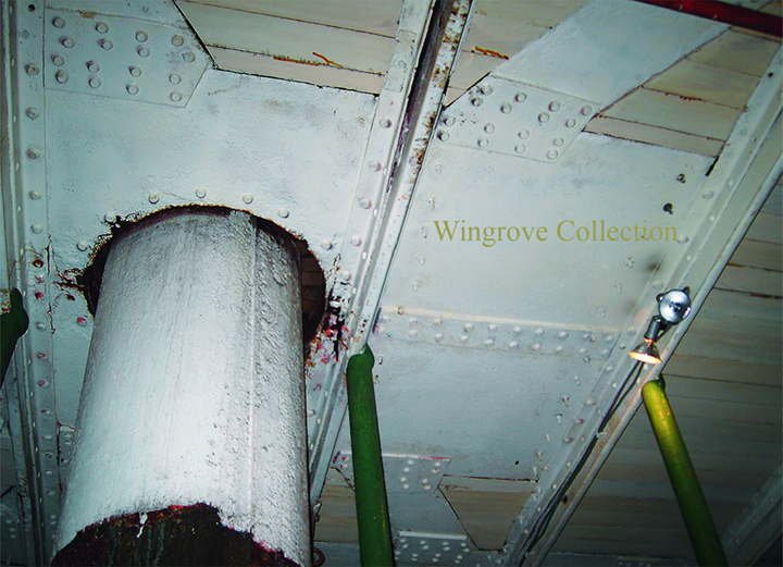
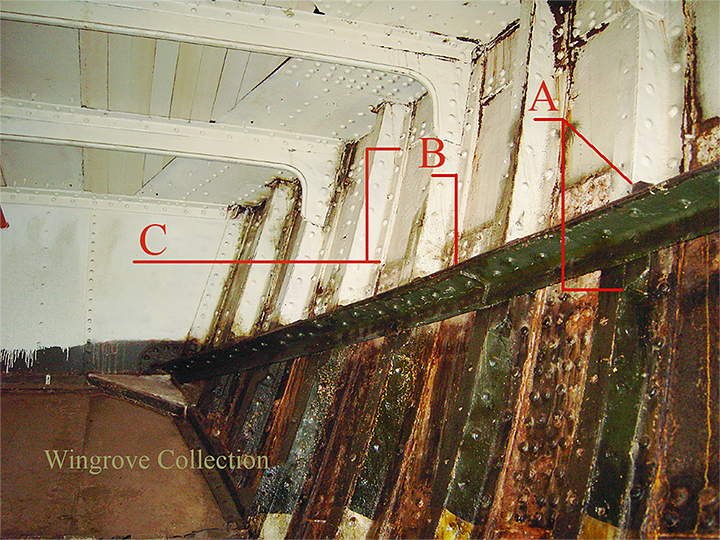
Fig- 78 - This is the inside of the Falls of Clyde hull - and shows the very good condition that she is in for the best part of her, being then, when I took the photos 130 year of age. At ‘A’ we can see the Stringer passing over a Frame, and the additional short bracket riveted to the back of the Frame and to the Stringer. At ‘B’ we see a joint on the lower of the two angle iron sections that form the Stringer. Note that you can actually see then end of the angle iron, this indicates that the joint is ‘Joggled’. I used licence at this point and made my joints as end to end or Butt joints, the reason being the making of yet another tool to form the Joggle, on something that on the model, will be next to impossible to see. However one can see why the Joggle joints was used, even though in the ship yard it made for much additional work. A Joggle is where the - in this case - the lower angle is double bent to ride over the one that it is to be jointed to. Thus the rivet here passes through three thicknesses of angle iron to form a solid structure. With a Butt joint the strength of the joint would be just that of the upper angle iron, for the lower one would be brocken. In later steel built ships the frames were put thought large machines to Joggle them to accomodate, the Out Plating, as would be the case at ‘C’. However as we will see at a later stage, and can be seen here, a narrow strip of iron plate is used as a filler piece to accomodate the Out plate, thus giving a firm foundation for riveting the Frame to the Plating, but more on that when we get to the plating.
- 281 replies
-
- 7
-
-
- falls of clyde
- tanker
- (and 2 more)
-
July 2017 Fig- 77- The side Stringers, two on each side, are each formed from two lengths of angle iron riveted together, and run the whole length of the ship. For the model these have all been run though the modified Single Rivet Head Maker (SRHM) see Fig-39, so that the rivets line up with the Frames. With double angle iron for the Stringer, and an additional short length of angle iron riveted to the side of each Frame where the Stringer crosses it, the connection provides for four rivets at each point. To assist in the location of the Stringer in the model, a short length of aluminium sheet is cut to represent the spacing and laid against the Bilge Keelson, while soldering the Stringer in place. Another is used against this to locate the second Stringer higher up the side of the hull until it is soldered in place using the carbon rod resistance soldering unit.
- 281 replies
-
- 12
-
-
- falls of clyde
- tanker
- (and 2 more)
-
Thank you Bill for your generous comments, welcome aboard, hope you enjoy the rest of the trip.
- 281 replies
-
- 3
-
-
- falls of clyde
- tanker
- (and 2 more)
-
Fig- 76 - The Keelson, Side Keelsons and Bilge Keelsons in place, ready for the side Stringers to be assembled.
- 281 replies
-
- 19
-
-
- falls of clyde
- tanker
- (and 2 more)
-
Fig- 75 - Here can be seen the benefit of the Carbon Rod soldering unit at work, as against the end bit of the modified soldering iron. With this unit only the very tip is heated and that for the split second necessary to make the previously tinned joint. It was improved still further at a later stage by making a simple tube of paper, to slip over the exposed part of the rod to insulate it from the rest of the model. Even with the modified soldering iron bit, it took forever to heat up, and was very cumbersome in such a confined space, with always the possibility of heating and unseating other parts in the process. At each point where a longitudinal member, crosses a Frame, a small length of angle iron is riveted to the frame, so the cross member can be held in place by 4 rivets to each frame. These, it may be remembered were soldered in place while the Frames were being individually made up (Fig-41)
- 281 replies
-
- 11
-
-
- falls of clyde
- tanker
- (and 2 more)
-
Fig- 74 -The Side Keelsons are made up from two lengths of angle iron, riveted to the tops of the frames, and in between these are riveted a series of plates called Intercoastal Plates. I have used licence here, in that I have made them as a single length cut to match the Frames, egg-box fashion, as it was a very convenient way of spacing the frames at the start. Short sections are now added to complete the assembly, the original brass angles being removed and replaced with longer ones butt joined to match the standard practice. In full size practice the Intercoastal Plates, would have had short lengths of angle iron cut for riveting them to the Frames on both sides and the ships plating at the bottom, so making a very strong assembly. As it was impossible to solder these in place, they were not fitted, also they would not have been seen in the finished model.
- 281 replies
-
- 7
-
-
- falls of clyde
- tanker
- (and 2 more)
-
Fig- 73 - I did mention some time back that if I were to build this again, then I would not start in the centre, but at one end and work out from there. It is at this stage that we see the reason why. Iron construction, consists of joining lengths of iron together, be it plate, bulb iron or angle iron, the lengths, other than for plate, being of about 40 feet long. The practice is that there is a minimum distance between these butt joins, in the main it is the distance of two frames, or 4 feet, scale size half an inch. With the Middle Line Keelson we have on the Falls of Clyde, made up of 4 lengths of angle iron, a centre plate, and a top plate, called a rider plate, each being for the angle irons 40 foot lengths, that of the plates, probably 20 foot long, and each section butt jointed together. However each joint being 4 feet from the next, as no two joints should be opposite each other, one can see a slight complexity becoming apparent. Add to this the fact that I started with the centre twenty Frames, which amount to 40 feet, then adding a further 10 Frames - 20 feet - to each end, it would have needed some planning had I thought of it at the start. However my concern was to get the Frames together, so a short length of Keelson was made up to do just that, then when all 40 Frames were in place, I remove this to make up the full length. As also with the Side Keelson and the Stringers. The parts are first tinned, then assembled on the Live Soldering Table, and heated with the Carbon Rod soldering unit to make the joints.
- 281 replies
-
- 5
-
-
- falls of clyde
- tanker
- (and 2 more)
-
June 2017 Thank you Druxey, one has to stop somewhere, otherwise one would have a complete hull, and see nothing. The aim of the project, is to show iron construction, and I considered the centre 40 frames ideal for this, as it encompasses the Main and Mizzen masts, a deck house and the pumps, together with sufficient of the structure to show how it all holds together.
- 281 replies
-
- 3
-
-
- falls of clyde
- tanker
- (and 2 more)
-
Fig- 72 - With the last Frames in place the Comb Clamps are attached to aline the tops of the frames, and make final adjustments to the deck beams where required, so that the deck Stringers can be soldered in place, thus now forming a single unit, that will hold it’s self together.
- 281 replies
-
- 19
-
-
- falls of clyde
- tanker
- (and 2 more)