
HOLIDAY DONATION DRIVE - SUPPORT MSW - DO YOUR PART TO KEEP THIS GREAT FORUM GOING! (Only 24 donations so far out of 49,000 members - C'mon guys!)
×


GAW
-
Posts
183 -
Joined
-
Last visited
Content Type
Profiles
Forums
Gallery
Events
Everything posted by GAW
-
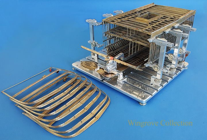
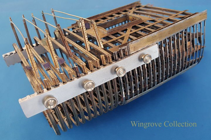
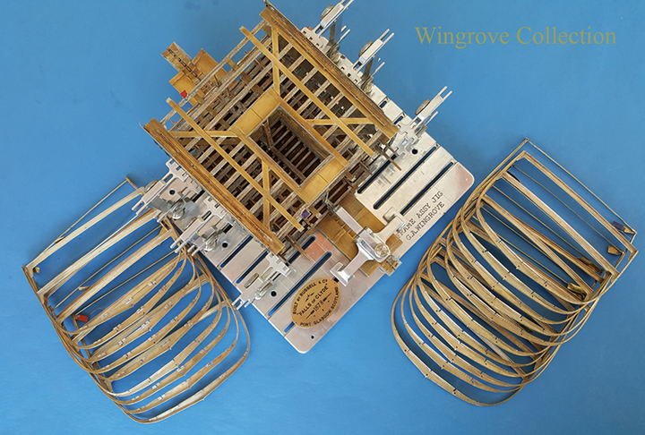
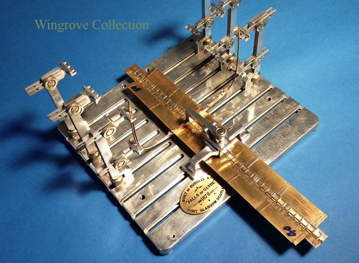
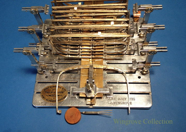
 Fig- 71 - As each frame is soldered in place at the bottom the assembly is moved through the assembly jig, here the last has taken it’s place. Forty frames in all was the aim of this project from Frame 40 to Frame 80. This includes the Main and Mizzen Masts, Crew accommodation and Galley, together with the Main Hatch and Bilge Pumps.
- 281 replies
-
- 13
-

-
- falls of clyde
- tanker
- (and 2 more)
-
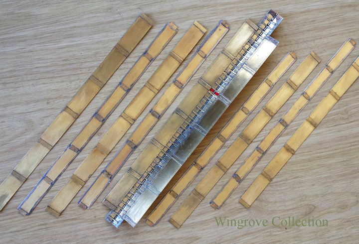
Fig- 70 - the final nine frames for this project, each tagged and numbered, eight on the left and the ninth in the assembly jig ready to be soldered in place.
- 281 replies
-
- 10
-
-
- falls of clyde
- tanker
- (and 2 more)
-
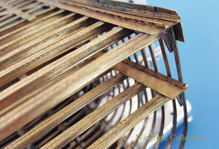
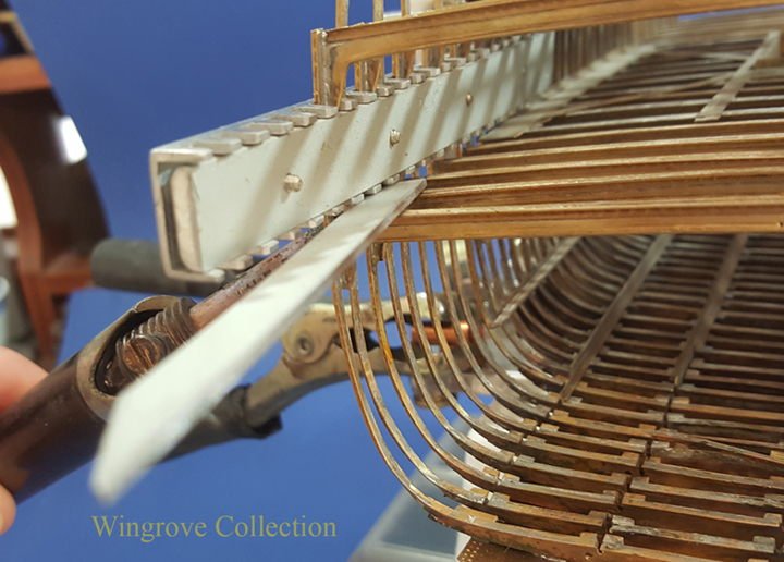
Fig- 69 - Here we see the Stringer plate in place on the Tween deck, together with an angle iron that would be riveted to that and each of the Frames. Note on the main deck a second angle is riveted to the main deck Stringer plate, the gap between the two being the Scuppers, with the deck planking butting against the other side.
- 281 replies
-
- 9
-
-
- falls of clyde
- tanker
- (and 2 more)
-
May 2017 Yes Rob you are slightly mistaken, by that I mean that many of the processes and stages have had to be done a second time, as the first has not always worked out, as is my usual practice - still learning about model making, one should never stop - however the overall creation is still the same one, hopefully improving all the time. My belief is that there are no such things as problems, what ever you are presented with is a series of answers, the tricky bit is finding the right one the first time. Some time one can see it as plain as day, but other times one needs to tread slowly in that direction, before finding it is a dead end - which is why one should always tread with care.
- 281 replies
-
- 3
-
-
- falls of clyde
- tanker
- (and 2 more)
-
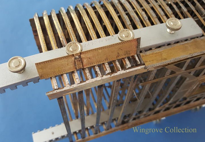
Fig- 68 - A brass angle, provided with the required rivet heads is soft soldered to the out side edge of the main deck stringer plating, this being soldered to the tops of the main deck beams. The vertical portion of the angle is then soldered to the top plate of the hull plating called the Sheerstrake, but not at the top, but a double row of rived heads below the top. The Sheerstrake plating connects - by rivets on the full size hull - each of the frames, to the main deck beams, via the Stringer Plates, and also to the Bulwarks above, hence the two rows of rivet heads above the Stringer Plate and angle. On a riveted hull such as this, there are IN plates and OUT plates. The Sheerstrake is an IN plate, meaning that it is riveted directly to the frames. The one below and the Bulwarks above being OUT plates. More on this later.
- 281 replies
-
- 11
-
-
- falls of clyde
- tanker
- (and 2 more)
-
Fig- 67 - Around the edge of the two decks are plates called stringers, on the tween deck, these are notched so that they fit around the frames. This is very useful in the construction, as it is a positive location for the upper portion of the frames, when the comb clamps are removed. The plates are soldered to the tops of the tween deck beams. Stringer plates are also fitted around the edge of the main deck, but as the frames do not extent above this, they sit on top of the frames and are soldered to the tops of the main deck beams.

- 281 replies
-
- 8
-
-
- falls of clyde
- tanker
- (and 2 more)
-
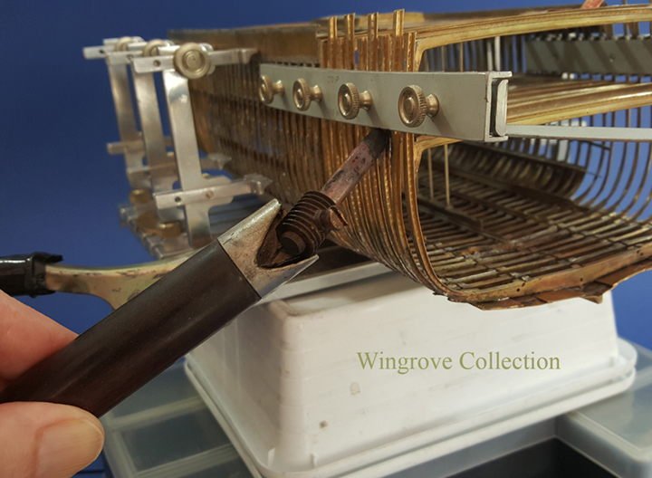
Fig- 66 - The slight adjustment of the deck beams here is accomplished by inserting a short length of aluminium bar, between the top of the beam and the underside of the comb clamp, and then applying heat to the soldered joint with the aid of the resistance soldering tip. With care this can be so set that it will soften the solder sufficient to slide the end of the beam to the right position. and then eyeing the result so all line up correctly. In full size practice the beam would have been held in place at each side with a couple of bolts, when the correct position was confirmed the riveting would have been completed.
- 281 replies
-
- 8
-
-
- falls of clyde
- tanker
- (and 2 more)
-
April 2017 Thank you both, your comments are appreciated - patients Druxey, all will be revealed in due time, I still need to prove to myself that they can be made to work, ie, can be tensioned, and for that I need the standing rigging - we have a long way to go yet. We will be jumping about a bit from time to time as to the sequence of operations and their description of the construction, as we are in this stage. There are two reasons for this: One - Because it being a first time subject, and the first attempt at some of the particular problems were not always the best, and the second attempt is the one demonstrated and recommended. Two - Because this is a staged model, four stages in all - the centre 20 frames, followed by an additional ten frames added to each end, and the fourth stage being the plating of the lot. This being so, in some cases it can be better showing and describing a particular part in the second or third stage, rather than the first. Fig- 65 - With the set of frames assembled to the keel, and the comb clamps attached to the top of the frames, and all aligned as to the radius at the bottoms and sides of the frames, it was found that some slight adjustment was necessary to adjust the position of the deck beams to perfectly aline them, with those already in position. This was a normal practice in the ship yards of the time, after all they were working and assembling enormous iron frames, that had been built up to match chalk marks on the loft floor, that had them selves been marked out from a 1/4” to the foot half model. Having read that for the first time, I did not feel too bad, having to adjust a couple of mine. In full size practice, these were all set out to the good eye of the yard foreman, slight adjustments to the frame shape to match it’s neighbours was dealt with by the use of a heavy sledge hammer in the appropriate place.
- 281 replies
-
- 9
-
-
- falls of clyde
- tanker
- (and 2 more)
-
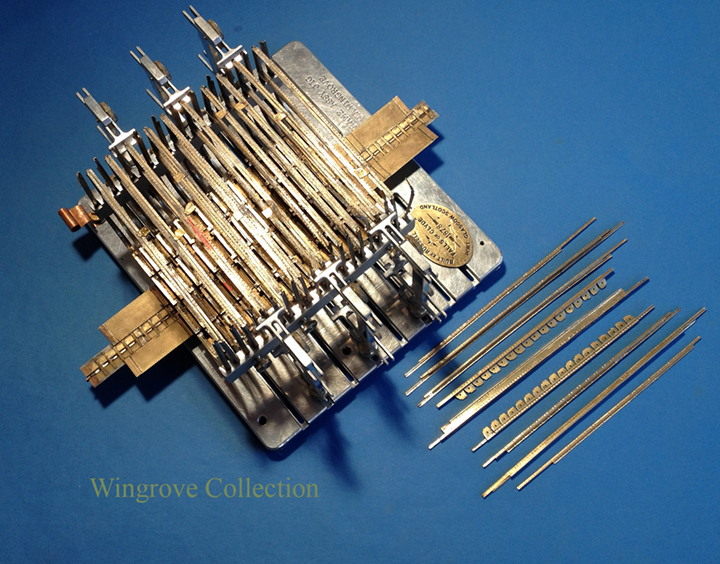
Fig- 64 - The Comb Clamps used to hold the Frame set in position, while the tops of the Frames are cut to the required hight. Each alternate Frame is fitted with two Deck beams that assist in keeping it’s shape after removing from the Frame Making jig. The other Frames, I have made extra long - high - and soft soldered a bar across the top, to help them stay in shape. Once they have been attached to the Keel and the lower Plating, and the Stringers soldered in place - that is about to take place here, the surplus above the main deck level is removed. As mentioned at the start of this project, when completed it will consist of three models of the Falls of Clyde. The Half Model, that we have already seen - The centre section being covered here - and a fully rigged waterline model showing her in all her glory, as originally built, a light grey hull, topped in white at the Forecastle and Poop, with the deck houses and detail painted white framed in mast colour - a dark sandy yellow. For those interested, this third model that I will cover here in due time, was stated a month ago, the first stages of which can for the next 4 weeks be seen on my web site, at ‘News & Comments’: < http://www.wworkshop.net/Home_Page_/News%26_Comments.html > For those who winced at all of the tool making required to build this model, the good news is that, other than using my standard model making workshop tools and machines, no new special purpose tooling have so far been required. In fact I see none, excepting possibly one for tensioning the wire standing rigging, but having got this far with the rigging screws, although they lack threads, I do see a simple way of setting a tension on them. This is one of the main reasons for making a sample of the possible problem corners before starting on the model it’s self. Once an item has been made and is sitting in front of you, it will show you a store of possibilities - or not, that cannot - for me at least - be seen with out making an example first.
- 281 replies
-
- 15
-
-
- falls of clyde
- tanker
- (and 2 more)
-
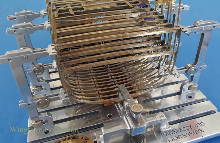
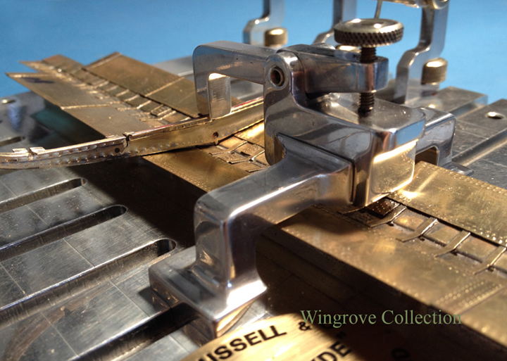
Fig- 63 - Eleven new frames in place and the assembly moved though the Frame Assembly Jig.
- 281 replies
-
- 12
-
-
- falls of clyde
- tanker
- (and 2 more)
-
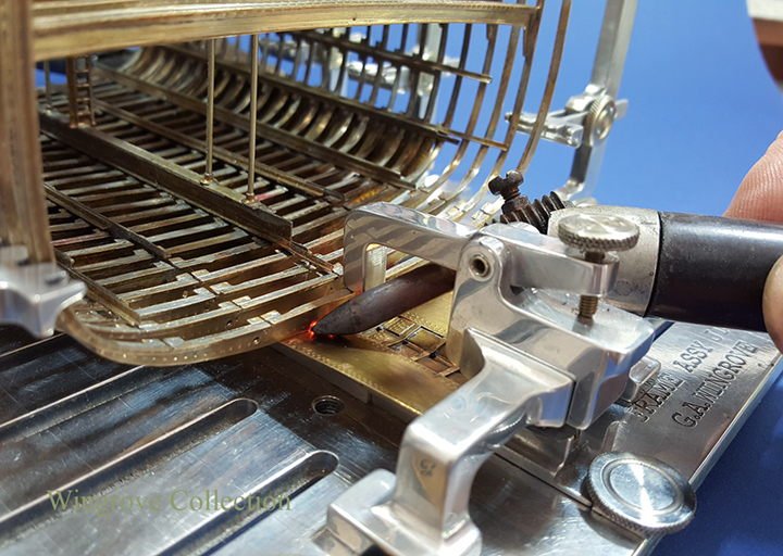
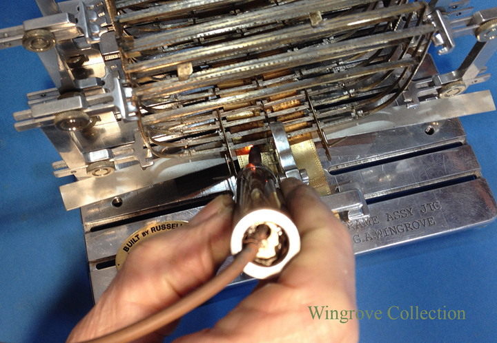
Fig- 62 - The Frame Clamp and resistance soldering carbon rod being used to melt the fragment of soft solder placed between the Frame and Plating.
- 281 replies
-
- 11
-
-
- falls of clyde
- tanker
- (and 2 more)
-
March 2017 Fig- 61 - Here we have the second batch of 20 frames, all made up in the same was as the first batch, excepting that each will have been formed to match it’s own particular aluminium pattern.
- 281 replies
-
- 10
-
-
- falls of clyde
- tanker
- (and 2 more)
-
To answer you Rob, he would need to be wealthy indeed, and I have met a lot of wealthy clients with the car models, they paid for my bread and butter for 40 years, classic cars are one things and Windjammers another. Consider that last year I completed a 1/15th scale Alfa Monza, a sister (full size) car to the original I used for the model sold last year for $11,990,000.00. While those trying to save the Falls of Clyde from a watery grave after surviving for 138 years and being unique in the world today, can hardly scratch together, so far, $150,000, of the 1.5 million needed to save her. The 1/96th scale Falls of Clyde - all three models of the series, just the first two here so far - I am making for my own entertainment, but when finished, and I need the room for the next project, will be donated to the Clyde Maritime Trust for display in the 3 masted Barque Glenlee, now fully restored, on the Clyde in Scotland. If we can get the Falls of Clyde back to her birth place on the Clyde, I live in hope - then the models and tools will be located in her. So one way or another, there WILL be a Falls of Clyde back on the Clyde for the public to see what a fantastic family of ships were once created there.
- 281 replies
-
- 11
-
-
- falls of clyde
- tanker
- (and 2 more)
-
Thank you folks, so pleased to have your interest, for more info on the tooling Michael, check out the pages on my web site, where each of the tools is broken down < http://www.wworkshop.net/Falls_of_Clyde/Menu.html> as also the aim of the project. I have not included it here, as I thought the aspect of building the actual ship model to be more in keeping with the web site content. The making of the tools took about nine weeks to design and create from scratch before any work was started on the model. Each of the tools has a particular function with respect to producing/modifying the parts for an iron ship, and as such could be used to build any iron or steel ship. The difference between building an iron ship and a wooden one, is that with timber each item is cut and shaped from a solid block. With iron the material is already of the required shape - flat - angle iron - and/or bulb iron, but a considerable number of tools are needed to manipulate them to form the parts of an iron ship's hull. The 20 frame centre section model, took about 11 months to complete, working perhaps on average about 5 or 6 hours a day.
- 281 replies
-
- 6
-
-
- falls of clyde
- tanker
- (and 2 more)
-
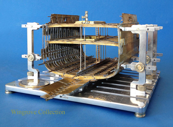
Fig- 60 The first 20 Frames in place, complete with Pillars, Ladder, Keel and Stringers and some Plating, which we will cover a little later in the proceedings. As may be imagined, having got to this stage - half way - I was very keen to see if I was on the right track with creating this model centre section, so added some Plating right up to and including a short section of the Bulwarks, stays and all - and it looked to me to be OK, I was on the right road. However, because I had started in the centre and so from now on had to work both fore and aft by adding another ten Frames to each end, most of this Plating became more of a problem than an asset, and was later removed, as we shall see, and refitted in longer lengths. We learn as we proceed. You may note also that the main hatch is also present on both the Main Deck and Tween-Deck. This was also removed and remade, and will be covered later, together with the reasons why - a cautionary tale.
- 281 replies
-
- 23
-
-

-
- falls of clyde
- tanker
- (and 2 more)
-
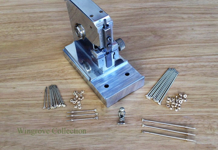
Fig- 59 Here we have the SRHM, set up for single rivet heads, two side by side for the top of the Pillar, and two - one on each side of the flange/collar that forms the base of the Pillar. On the model Pillar, a small brass plate is silver soldered to one end of a nickel silver rod, filed to shape, bent to accomodate the bulb iron of the beam and provided with two rivet heads, after which it is tined with a little soft solder, ready to be attached to the beam. Short Pillars for the Main Deck to the Tween- Deck, and longer ones between the Tween-Deck and the Keel, note Jock the riveter, alway useful to have him around to remind one of the scale.
- 281 replies
-
- 10
-
-
- falls of clyde
- tanker
- (and 2 more)
-
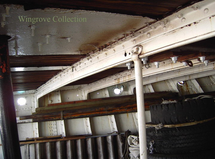
Fig- 58 The Photo was taken on the Falls of Clyde, showing a Deck Beam and the Pillar that supports it in the centre. Of note is the flat forging of the top, that wraps around the bulb iron of the beam, to which it is then riveted with two rivets. At the foot is a ring in the form of a collar and flange, the flange being attached to the angle iron of the beam below with a further two rivets
- 281 replies
-
- 7
-
-
- falls of clyde
- tanker
- (and 2 more)
-
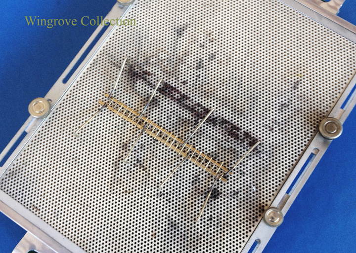
February 2017 Fig-57 We have the Main Deck, the Tween Deck, and the Hold Floor. Logicality told me that there had to be a Ladder somewhere to join them all together, so made one and fitted it to the Main Hatch. Who knows if it ever was there, but I felt that it does serve it’s purpose of joining the three levels together. As can be seen it consists of two lengths of brass angle, drilled to take 020” pins for the steps. A bit oversize making them two inches in diameter full size, but for me when getting down to this size and detail, if things start to disappear because they are so fine, one will miss them, so better to go a little oversize to show they are there. A personal feeling in this work. This is a question one has to ask oneself all the time in scratch building. In this case I feel it is permissible, but had other items been very close by to show up the ‘licence’, then maybe I would have made them more actual scale size - ’010” one inch in diameter. The pins were silver soldered in place, pin ends filed flush and the angle flat reduced to half it’s width. This detail was removed from the ship when the tanks were fitted, but there is a ladder down the face of the watertight bulkhead, forward, that looked much like this. For fitting it was provided with a spot of soft solder at the top and bottom together with where it passed through the Tween Deck Hatchway, and soldered in place with the carbon rod soldering unit.
- 281 replies
-
- 7
-
-
- falls of clyde
- tanker
- (and 2 more)
-
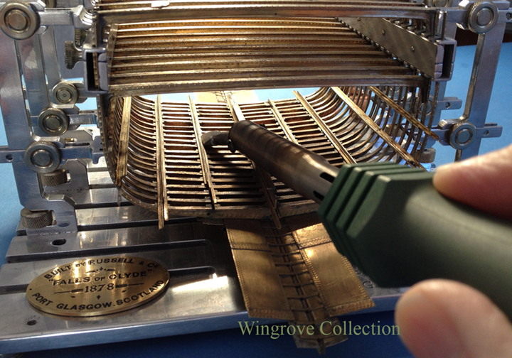
Fig- 56 With all the parts ready tinned and slotted in place, it was just a matter to run the heat along each side to fix/melt the solder and fix them in place. Here I have modified a copper soldering iron bit to give me a short length of hot iron. However I did find that it took forever to heat up enough to do the job, and finally resorted to filing up to the same shape, to the end of a carbon rod and using that. In use, one needed to make contact with the parts with the tip of the rod, then with the foot switch, switch on a low power, and just slide the heating carbon tip along the top of the pre- tinned angle, then switch off and remove the carbon tip. My concern in not using the carbon rod at this stage, was the shorting of the rod against the other metal parts deep down in the hull should I inadvertently touch them - easy done. Shorting is the only danger with the use of the resistance soldering unit, if the live rod does touch another part, one will get ‘spark erosion’ ie a hole in that part. However some further experiments, showed that all I needed was a thin tube of paper - any paper - around the rod with just the tip showing to solve the problem, as will be seen later in the project. The heating at the tip is not on long enough to set the paper on fire, but even if it did, it would course less damage than ‘spark erosion’. As I remarked earlier, this is flying my the seat of your pants, you learn as you go along, hopefully doing as little damage as possible in the process. Note that the end of the Comb Clamps can be seen at the top on the assembly on each side at the tween deck level.
- 281 replies
-
- 11
-
-
- falls of clyde
- tanker
- (and 2 more)
-
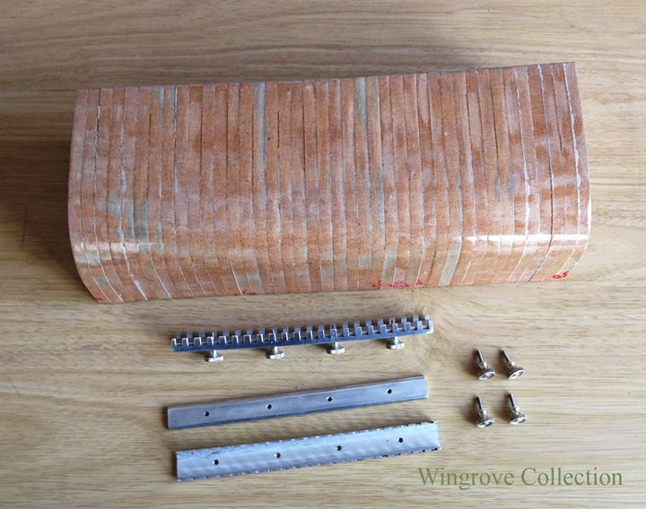
Fig- 55 Here we see a pair of clamps machined from an aluminium ‘U’; section, the slots corresponding with the spacing of the frames. It is made in two parts, the outside being the ‘U; section, while the inside is a flat aluminium plate. After machining the slots and assembling the inner plate, secured with four knurled screws, it was bent on two planes, to match the assembled middle Frame Master Patterns, to copy the slight curve of the deck and also the very slight curve of the out side of the hull in the centre section. The adjustable uprights on the Ship Yard can locate and accomodate 9 Frames, OK for assembling them on the Keel, and allowing the Hull to pass through the Ship Yard, but not good enough to locate sufficient Frames for assembling the longitudinal members in their rightful places with precision . These Comb Clamps, as I call them, will hold 21 Frames at the tween deck level, in exactly the correct place for fitting all of the Stringer Plates and most of the ships plating.
- 281 replies
-
- 7
-
-
- falls of clyde
- tanker
- (and 2 more)
-
Fig- 54 - These are the parts shown in Fig-43 being assembled on the soldering table, shown here, bottom right, ready to be assembled into the centre 20 frames. They consist of the Keelson - properly called a ‘Middle Line Single Plate Keelson’, made up of a centre plate, with two angles riveted at the top and two at the bottom, and a second plate riveted on the top called a Rider plate. Next out on each side are the Intercoastal Side Keelsons, one on each side, consisting of a series of plates joined together at the top with an angle on each side. Then follows further out, the Bilge Keelson, comprising of a length of Bulb iron, with an angle riveted to each side. The final longitudinal item is the Bilge Stringer, that consists of just two lengths pf angle irons riveted together, at which point we are now starting up the side of the inside of the hull. All of these are directly riveted to the frames where they cross. NOTE substitute soft solder where you see riveted, one is real life the other ‘in miniature’. The Intercoastal Keelson, in fact consists of a series of plates set between the frames at this point, each of the plates is riveted to the Frame fore and aft with a small angle bracket, and also to the ships Plating below. The tops are joined together longitudinally with a length of angle iron on each side, all riveted together. This is where I have used licence, and not followed standard practice, adjusting the parts to meet my needs. These being to make the plates as a single length, but slotted, to fit slots in the frames, so as to assemble them egg box fashion. With the slots precision cut, it allowed the frames to be placed at the bottom level exactly were needed and squared off to the Keel. I did not fit each plate with brackets to the frames fore and aft - (1) because it was almost impossible to get to them with a heating device to solder them in place at each station, and (2) they could not be seen in the model when finished if I had included that detail.
- 281 replies
-
- 9
-
-
- falls of clyde
- tanker
- (and 2 more)
-
Fig- 53 - Using the resistance carbon rod tip to heat the parts to melt the sliver of soft solder between the frame and the garboard strake of plating that can be seen going together in the Fig-52.
- 281 replies
-
- 7
-
-
- falls of clyde
- tanker
- (and 2 more)
-
January 2017, A Happy, Healthy and Productive new year to you all, and thank you for the comments and advice, we never (should) stop learning - and no Mike Y, no place for Welding Robots in a ship yard of 1878 that is why you will find Jock the riveter, turning up from time to time here, as in Fig 40. Yes Mirabell61, the tools are basic, ie, made to do a job, if the project is a riveted iron or steel ship, then these tool could be used to make it. I should point out here, that the tools were all made before the model was even started - I brain stormed for 9 weeks, to imagine my self through the project, building the tools as I went. Now at this end of the completed project, I and perhaps your good selves, can see more simple ways of doing these things. But the other side of that, is that I am finding some of the tools very useful in other modelling field as well.
- 281 replies
-
- 3
-
-
- falls of clyde
- tanker
- (and 2 more)
-
Seems the photos have come over in the wrong order again - they arrive correct for the preview, then get mixed - if some one could adjust the order at your end, I would be most grateful.
- 281 replies
-
- 1
-
-
- falls of clyde
- tanker
- (and 2 more)
-
December 2016 Fig- 49 - Please bare in mind that there is a big BIG learning curve for me in this build - a first time for me, and as no one that I know of has written anything on the subject of building an iron ship in miniature, it is called flying-by-the-seat-of-your-pants, so many mistakes on the way, most of which will be shown as is. Here we see the first stage in making up the ships plating - Sets of six plates, complete with rivet heads and Butt Straps, ready to be assembled/attached/soft soldered to the Garboard Strake. The mistake is that although the first couple of strikes of plating will be in a straight line, there after, there will be a very slight curve in them. At the 4th -&- 5th strakes it is very slight indeed, but if ignored, can give big problems later on. It is still possible to make up the plating in lengths of several plate such as this, but we will see later, a very simple way to finely adjust that all important curve in laying up the plates. Note the small strap across the Bar Keel between the first strake of Plating on each side, at the point of contact for each Frame. The Frame must be in contact with the ships Plating at all points to be able to be riveted to it. As the Plating is in the form of One in and One out, a filler piece is required between the ‘Out Plate’ and the Frame at each point of contact. Fig- 50 - The ‘Ship Yard’ - the last of the tools. This consist of a precision machined aluminium plate with grooves to hold columns on which are mounted a series of arms to hold the frames in place and vertical while they are assembled to form the ships hull. Six columns are provided each of the columns has two arms, with three fingers at the end of each. These correspond to the spacing of the Frames. All of the parts are fully adjustable at all points, so could accomodate the Falls of Clyde hull for it’s full length. Although the plate will only hold 24 Frames at one time, the Hull, as we will see, can be moved through the ‘Yard’ as the build progresses. The centre of the plate has a groove down the full length that contains a carriage, to which the Bar Keel and Garboard Strake assembly is held in place with a clamp. Over this is a mechanism/clamp, also fully adjustable, to hold the individual frame in place while it is soft soldered to the assembly below, the top of the Frame being supported at two points on each side, by the fingered arms on the columns as can be seen, The columns and the frame clamp can be relocated to any position on the base plate to suit the job in hand. Provision is also made to make the whole assembly live, when connected to the resistant soldering unit, the essential means by which all of the soft soldering is undertaken on the hull assembly Fig- 51 - The Frame Clamp set up with a Frame under the business end, while the sides of the frame is held perfectly vertical by the fingered arms attached to the columns on each side. Note the PIP at the bottom of the Floor in the centre, which is set over a corresponding hole in the Bar Keel made to take it, and so locate the frame in its correct position. The next step is to flux the area to be soldered, slip in between the Frame and the Keel assembly a small sliver of flattened soft solder, adjust the clamp to press the parts together, and apply heat to the precise area with the live carbon tip to fuse the parts together. Fig- 52 - Here we see the first series of frames being assembled to the keel, with the next Frame ready to Go-Up. The fingers on the column will then be slid in and be locked in place, once the frame is lined up with it’s neighbours, a solder tab slid in place at the bottom, clamp applied, heat applied, assembly moved forward and process then repeated until all the required Frames are in place. Note that it is only alternate Frames that have deck beams, and that each is provided with a tag holding it’s number. With twenty Frames made and ready for assembly at the centre section of the hull, all seemingly of the same shape and size - which they are not - big problems are there for the unweary. Note also the seeming disk at the bottom of the photos. This is in fact a reel of soft solder that has been passed through the flat rollers of the RHM to make it paper thin, then trimmed to three fingers. These are snipped off as required and used to sit between fluxed and tinned parts to be soft soldered together. Apart from the use of tinning parts - applying a thin layer of soft solder to the part - the soldering iron is not used at all in the assembly of the hull. The reason being that it will of necessity leave a solder residue after it’s use. Here the soft solder is used in place of the actual rivets, so none should be visible in/on the finished joint. The only way - that I have found - is to use a minimum amount on each surface - tinning - and place a very small - tab/sliver - of solder between the parts. Then hold the parts together and apply heat - in this case with the tip of the resistance soldering carbon rod.
- 281 replies
-
- 15
-
-
- falls of clyde
- tanker
- (and 2 more)