HOLIDAY DONATION DRIVE - SUPPORT MSW - DO YOUR PART TO KEEP THIS GREAT FORUM GOING! (Only 24 donations so far out of 49,000 members - C'mon guys!)
×


GAW
-
Posts
183 -
Joined
-
Last visited
Content Type
Profiles
Forums
Gallery
Events
Everything posted by GAW
-
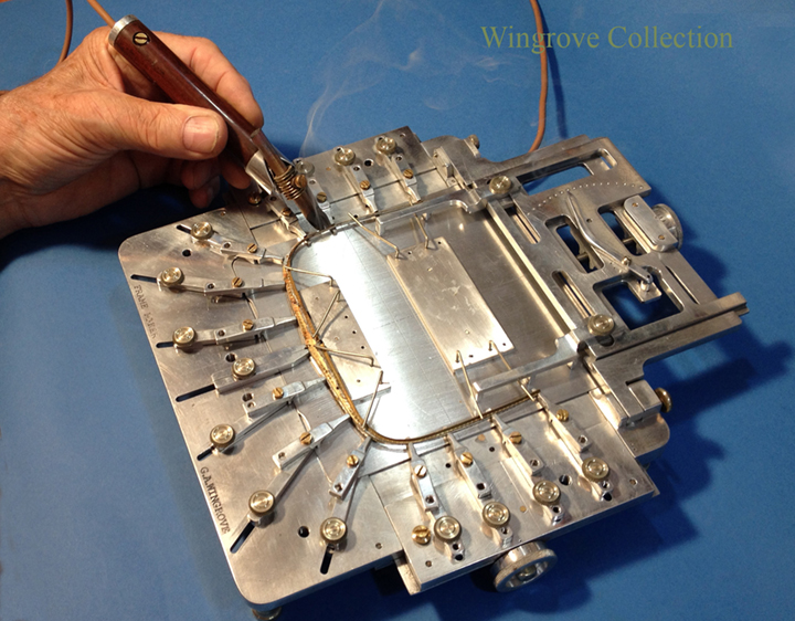
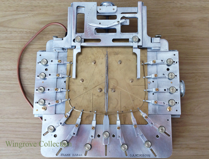
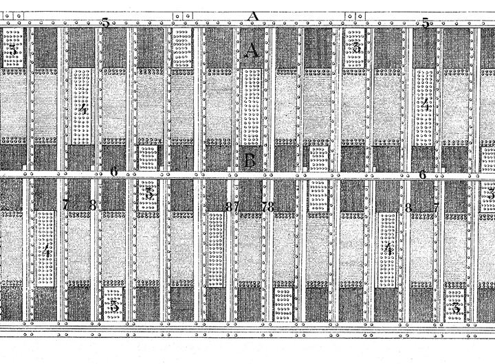
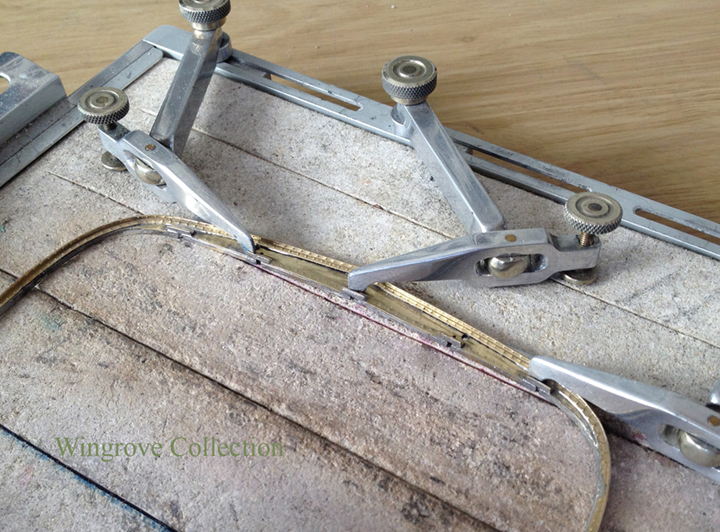
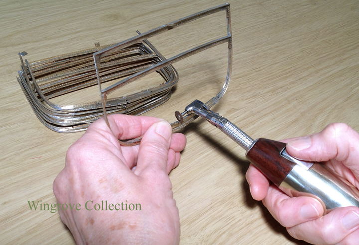
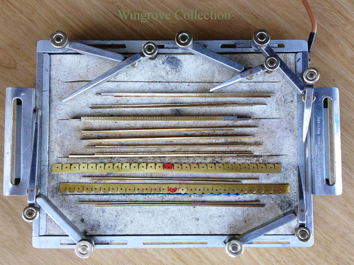
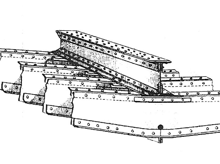
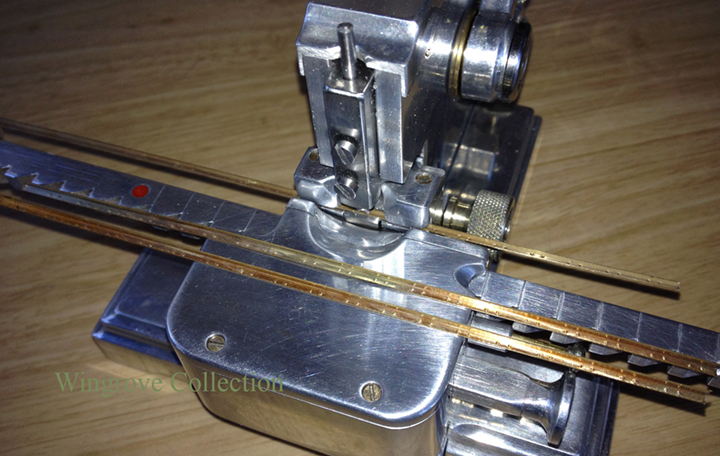
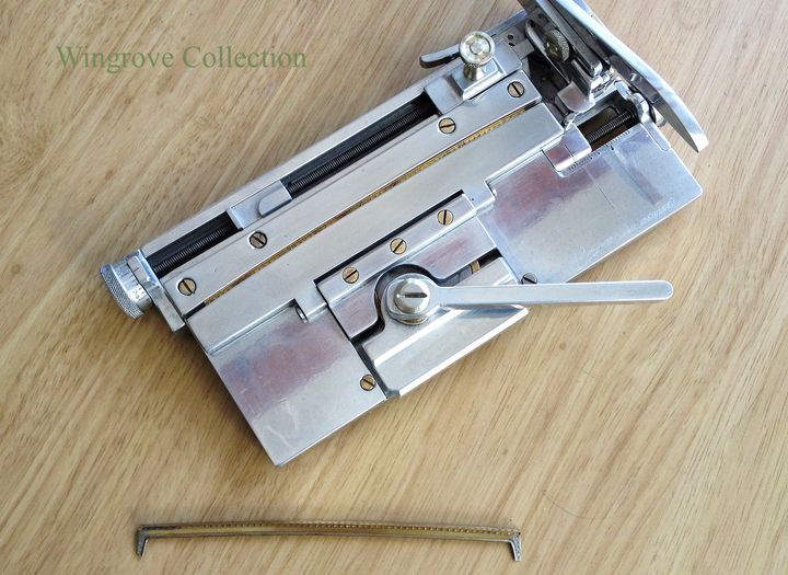
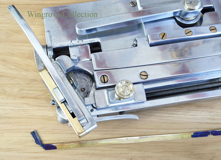
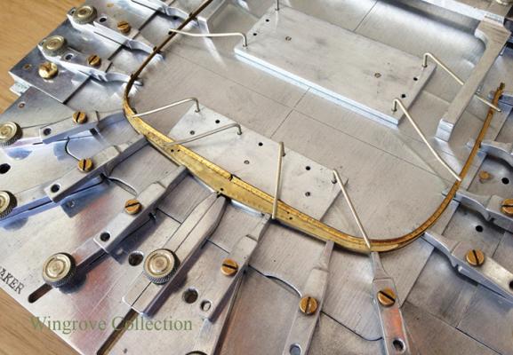
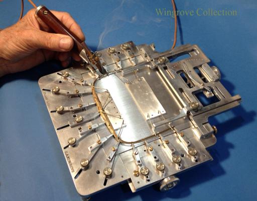
 November 2016 Fig- 45 - Here we see the Garboard plates being soft soldered to the Bar Keel, held firmly in an aluminium jig, that is it’s self clamped to the live soldering table. The cage on the top can be slid along the plates, as the soldering progresses. This is again the resistance soldering unit in action, that I feel is paramount in this sort of work, where a soldered joint is required, with out visible soldered - or nearly so, depending on your skill. Fig- 46 - Now we come to the ships plating in general and the first thing of note is the ‘B’ in the centre, and the frames on either side. This represents the centre of the riveted iron hull. Note that the rivet heads are on each side of this opening between the frames, whereas fore and aft of this point, they are on the aft side forward of this point, and on the forward side aft of this point. To understand the reason for this we need to go right forward and right aft to see what happens to the frames as they bring the plating to the stem and stern posts. In the centre of the hull the out side flat flange of the angle iron frame is at right angles to the frame. As we move fore and aft of the centre line, an ever increasing angle has to be formed on this flange, relative to the frame across the hull. As we move forward for example this angle becomes very acute, such that if the flange was forward of the frame it would be impossible to attache the rivets to it as the angle becomes less with each frame. By having the flange aft of the frame , the angle increases, so allowing more room for the riveters to do their work. And the same for the rear frames of the hull, with the flat forward of the frame, the riveter has the maximum space in which to work. This would appear to not make a great deal of difference with regard to building the model, as the rivet line - flange of the angle iron - are still placed two feet apart. However in making the Floors, I did leave a small pip at the bottom of each, to assist in locating the frames to the Bar Keel. This means that at this centre point all frames forward are reversed, thus requiring the Floors to be on the opposite side of the frame, so the locating holes for the Floors, needed to be plus one angle iron width further apart at the centre. This is why there is a red mark on the bar keel, each side of which these two holes are located, showing the centre of the model hull. Fig- 47 - The Bar Keel is now assembled with the Garboard Strake of plating on each side and awaiting the Butt Straps to be riveted/soldered across the joints where the plates butt against each other. One big mistake is visible here, and was something that had to be watched for at every stage of the construction and that is, that the Bar Keel has ended at the same place as the Garboard Strake plating. This is a fatal error as all joins in plating, stringers keel parts, should be at least five frames from the next, as it weakens the structure. In this case it should have been places in the centre of the Garboard Strake and not at the end. This was amended later, but it was a problem having decided to start construction at the centre of the hull. If I were to remake this model, it would be started at one end and work through to the other, but this is a learning curve, and I was still at the bottom of it. Fig- 48 - The RHM is now being used to provide the rivet heads on the ships plating, together with strips, later cut to length for the Butt Straps. With the adjustments built into the tool it is possible to run any number of rows of rivet heads as required, and with a little practice to have them all start at the same point. Although looking at the riveting on the inside of the hull on the actual ‘Falls of Clyde’, they ware not so accurately placed as one might imagine. The rivet heads are only visible on the inside of the hull as the heads were counter sunk on the out side, to give a smooth flow to the water around the hull, an important consideration when all you have is the wind as your motive power.
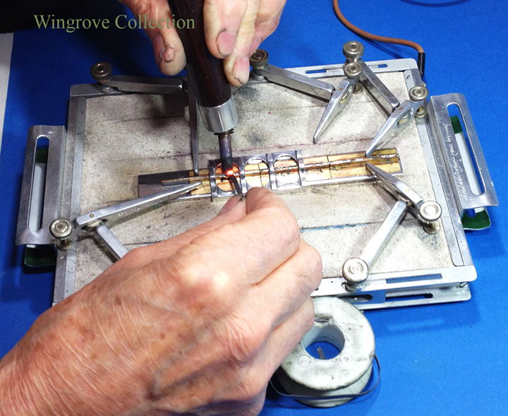
- 281 replies
-
- 13
-

-
- falls of clyde
- tanker
- (and 2 more)
-
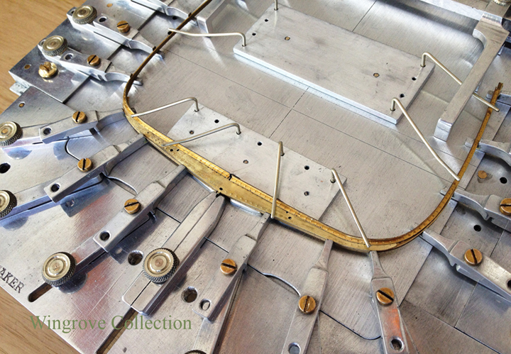
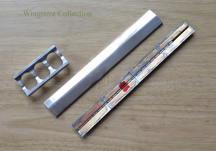
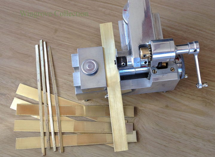
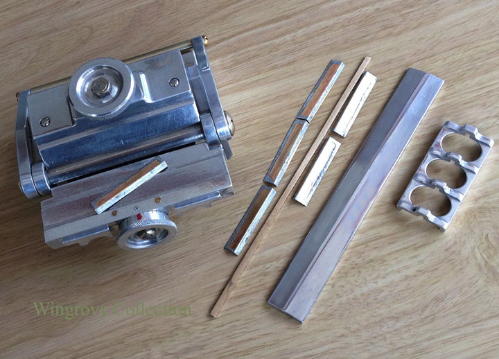
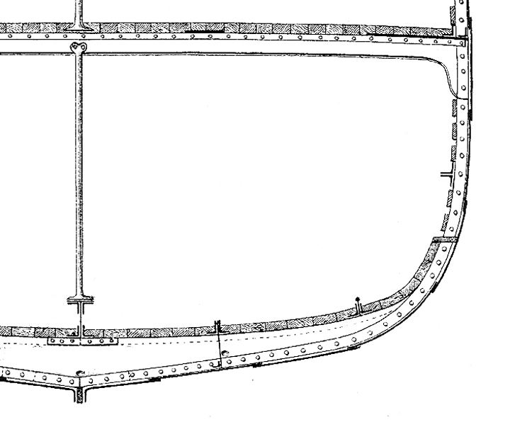
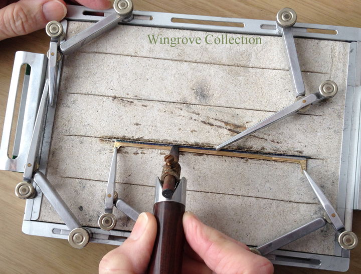
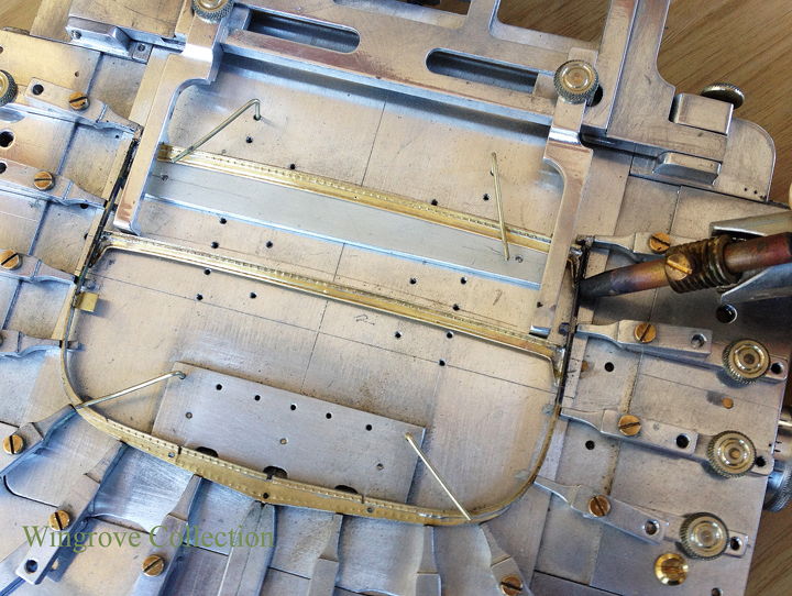
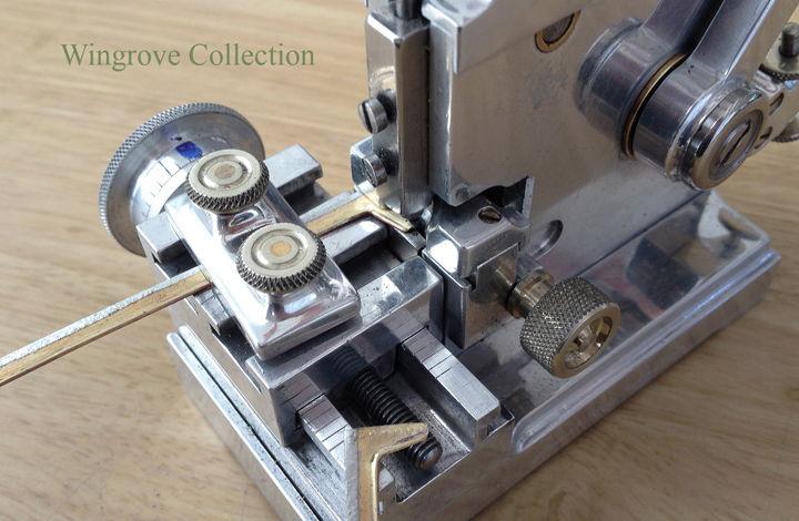
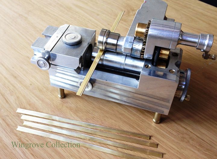
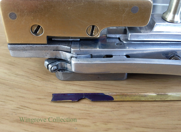
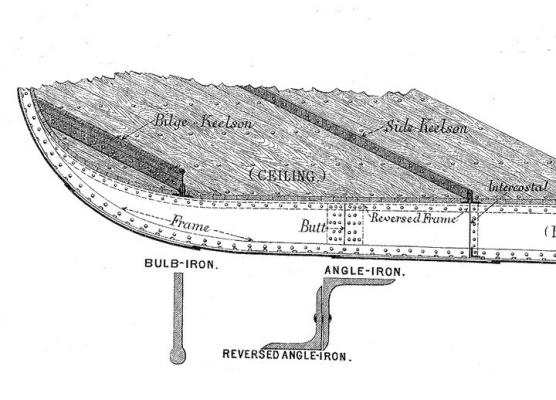
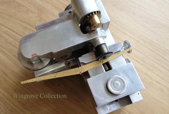
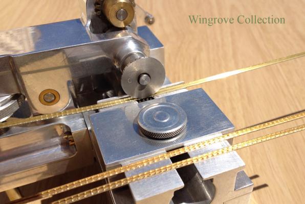
October 2016 Fig-41 - Each position on a Frame where a longitudinal member - Keelson - Side Keelson - and Stringers etc. cross it, requires a small bracket riveted to the opposite side of the Reverse Frame. At the point that we are at now, the Floor will be between the two. This allows the cross member that will be made up of a least two angle iron parts, to be riveted in four places each time is crosses a Frame. Here we see one side of the soldering table, used to hold three of these angle brackets in place. With the parts pre-tinned, and this side of the table being live - connected to the resistance soldering unit - one touch of the carbon rod at each section, is all that is needed to secure the joints. Fig-42 - In April - Fig-18 - I made mentions of my use of licence in making a small slot in the top of the Floors to assist in locating the longitudinal member in the final assembly. Here we see this locating slot extended across the small angle brackets, as also across the Reverse Frame. The slot only extends down to half the depth of the angle, so that in the final assembly the part of the Keel or stringer engaged in the slot cannot be seen, but is sufficiently deep to locate the part. Fig-43 - The longitudinal members on the inside of the hull of the Falls of Clyde consists of the Middle Line Single Plate Keelson, (Keelson for short) made up from a length of iron plate, with angle iron riveted to each side at the bottom and a further two lengths of angle iron riveted to each side at the top, and on top of this a length of flat plate riveted to the last two angle iron sections - the bottom two being riveted to the Frames, four riveted per Frame. Out side of the Keelson, on each side are the Side Keelsons, made up from two lengths of angle iron riveted to a set of plates, called an ‘Intercostal’ - these extend down between the Frames, and are riveted to the frames on each side and the Plating at the bottom by way of short lengths of angle iron. The next across the ‘Ceiling’, just to confuse you, this being the actual floor, are the Bilge Keelsons, again one on each side. These consist of two lengths of angle iron riveted together with a length of Bulb iron between. The photos shows these being assembled with soft solder on the soldering table. The two slotted lengths being for the Side Keelsons, the individual plates forming the Intercostal. These slots engage with the ‘licensed’ slots in the Floors so that the Frame assembly goes together ‘egg box fashion’ which greatly facilitates the complete assembly of the hull structure. In full size practice the ‘Intercostal’ plates would be assembled individually between each pair of Frames. The red markers is very significant and I will deal with them next month Fig-44 - Another Tool and another Jig - The lowest row of Plating on the hull is called the Garboard Strake, which attaches the Frames to the Keel - this being a substantial length of thick iron, it’s purpose is to protect the ships Plating should it run aground. - It is the Keelson on the inside of the iron hull that is the backbone of the hull construction. Each of the plates for the Garboard Strake has to be bent, with each bend being very slightly less than the last, from the centre out to the stem and stern. The Bending Tool, has micro adjustment to allow for this, although in the case of the forty centre frames for this model, the difference in angle was very slight indeed. The bar and cage jig illustrated are for the assembly of the Garboard plates to the bar Keel. The cage has a groove machined down the centre to accommodate the keel, the width of the cage being equal to the width of both plates, with the keel between. The second half of the jig consists of a length of aluminium with two flats set at the angle corresponding to that of the Frames at the centre of the hull. This served for my forty frames, with a little adjustment for the extra angle at each end. Had I intended to complete the Hull, then further jig plates would have been required to accommodate the differing angles as I proceeded fore and aft of the centre. Although in practice, once the Garboard Strake for several plate lengths were in place on the bar Keel, and this attached to the first few Frames, it was less of a problem fitting the remainder. In use the Garboard Strake plates are assembled on the aluminium bar, together with the bar Keel, with the aluminium cage over the assembly. With all parts previously tinned with soft solder, and all of the parts lined up to their intended positions, it is a simple matter to heat and melt the joints together with the Carbon Rod tip in the gaps of the cage, which can then be moved along the jig as required.
- 281 replies
-
- 12
-
-
- falls of clyde
- tanker
- (and 2 more)
-
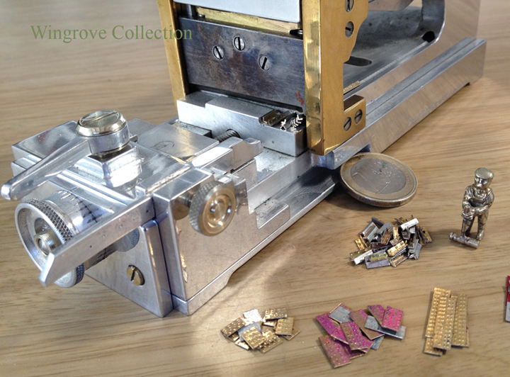
September 2016 - Apologies for the slight delay in this one, it is the holiday season after all. Thank you folks, your generous comments are much appreciated - all of the tools are designed and custom made by me for the job in hand - a workshop is a never ending delight, when ‘almost’ all things are possible. Fig-37 - So we now have a set of Ships Frames, well almost, there are still some fitting to be made and attached before we can start to assemble them, however I first needed to know what problems there could be in the process before advancing to that stage. Apart from a model ship yard - jig - required to hold all the parts together, there appeared to be two further machines required before I could get to that stage. Fig-38 - All of the Ships Frames run across the hull, for obvious reasons, but what holds these together are the Keels and Stringers, in the first place, after which the Ships Plating, which we will come to later. The Keels and Stringers presented a particular problem. The Frames are set at two feet intervals - scale size one quarter inch, indicating that rivet heads, now need to be placed very precisely on the angles at these distances, further, that two rivet heads are needed at each frame crossing, as at each such point a small angle bracket was riveted to the Frame on the opposite side to the Reverse Frame. So in the case of a Stringer made up of two Angles riveted together for their full length, where this crossed a Frame, it was riveted to it with four rivets, two to the Reverse Frame, and two to the small angle bracket. Fig-39 - The placing of the Rivet heads on the brass angles to be used to make up the Keels and Stringers, now needed to be placed exactly 1/16” apart at 1/4” intervals. I did consider a spiked wheel as with the previous rivet head maker, but the larger gap between the spikes would not allow it to work satisfactorily, so a new solution was required. This was to replace the single pin in the Single Rivet Head Maker (SRHM) with a double one with the two points formed exactly 1/16” apart. To place these at 1/4” intervals I devised a stepping mechanism that attached to the front of the SRHM, in place of the adjustable table. With the brass angle clamped to one end, this provided for twenty stops, equivalent to 40 feet of angle, which was about right for the lengths used. For those interested in the mechanism, detailed photos can be found here < http://www.wworkshop.net/Falls_of_Clyde/Gallery-12.html > Fig-40 - Before the Stringers and the Keels can be attached hundreds of very small angle brass brackets, each provided with rivet heads on both angles are required, all cut to exactly the same length, and for convenience, cut from pre tinned material. Also required further down the line are the Ships Plates together with their Butt Straps, among other parts, again all needing to be cut to an exact length, and many times over. For this I created a precision Guillotine with a hardened gauge plate cutter formed in two sections. The main form of the blade provides for a long straight cut, but on the right side the blade is formed into a small ‘V’ for cutting the angled brass, with a ‘V’ed channel running up to this, so allowing the brass angle to be cut and not deformed in the process. The Guillotine is so made that it is provided with micro adjustment of several stops, that can go down to two feet and up to 40 feet, in scale size of course. Note Jock the riveter, I made him early on as a guide to proportional size on all things, and found him very useful for the purpose. Construction details of the Guillotine can also be found on my web site.
- 281 replies
-
- 11
-
-
- falls of clyde
- tanker
- (and 2 more)
-
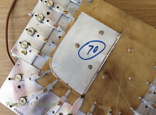
August Fig-33 - With the ships beam formed of Bulb Iron, and the brackets cut - bent -and the opening filled with a plate, originally hammer welded, but in this case silver soldered in place, we are ready to complete the beam for fitting into the Hull Frame. First the ends are trimmed to the correct length, then two brass angles - with rivet heads formed, are soft soldered to each side of the top edge, this being undertaken on the soldering table with the aid of the resistance (carbon rod) soldering unit. A thin groove is cut into the soft soldering block and one tinned brass angle placed in it. The tinned beam is placed on to this, with a second tinned brass angle placed on top of that. Care is now needed to aline all three so that they meet at the top edge of the beam for the full length, at which point the carbon rod can be applied to heat the parts, melt the solder and fix the joints. Fig-34 - Here we see the second tool, built into the ‘Beam Making Tool’ (BMT), used to form the curvature of the deck beam. It consists of a double action cam operated press. The working end consists of two thick plates, with a matching curved surface to form the camber of the deck where they meet. The lower one, next to the operating handle, being fitted with a hinge, and a groove across it’s face so that it can be turned up, to allow the finished beam to be placed into the groove. When returned to it’s lower position, the handle is pulled, thus forcing the two plates together, and forming the camber to the deck beam. All beams have the same curvature, they only difference is in their overall length Fig-35 - We now return to the FMG, the top portion of which is the beam setting tool. This consists of a hinged frame, to which are attached two adjustable fingers with cut outs to locate the two deck beams, The distance between the tween deck and the main deck will be the same for the length of the hull, but the distance between the keel and the two decks will change as we pass along the length of the hull. To accommodate this a micro adjustment has been provided to the platform holding the two fingers with the deck beam stops. Each of the original aluminium frame plate patterns is so made, that the top of the plate represents the position of the topgallant rail. With the master frame pattern in place in the FMG, a small setting block - so made to set the distance from the top to the main deck - is used to clip over the top of the pattern, so that the fingers can then be adjusted to their rightful position for the two deck beams. The pattern plate is then slid out from the top of the jig, and replaced with the aluminium soldering table. With the frame now fitted and held in place with wire dogs, the two beams are fitted in place up against the finger stops.. With the end brackets already tinned, it just needs a slight heat from the carbon rod to remelt the solder and secure both the beams in place. Fig-36 - The first set of ships frames complete with deck beams and number tags, ready for the next set of fittings before being assembly to the keel.
- 281 replies
-
- 12
-
-
- falls of clyde
- tanker
- (and 2 more)
-
For the moderator - had problems adding the photos this time, could not get them to upload in the right order, perhaps you can adjust them at your end please - Gerald
- 281 replies
-
- 1
-
-
- falls of clyde
- tanker
- (and 2 more)
-
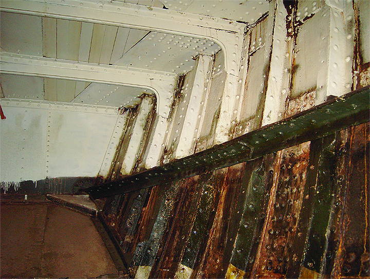
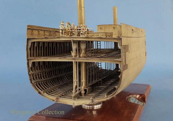
July - 2016 Fig-29 - The Beam Making Tool (BMT) - this is actually two tools in one The first I had much trouble with, attempting to copy the original method by making a cut in the end of the beam at the bend point, and then bending half to form the knee, leaving a triangular opening to be filled with a piece silver soldered in place. As I stated last month, the brass would split every time. So I ended up with converting the cutter to a clamp, which then solved the problems. The half of the BMT shown, consists of a pair of clamps. The one on the right being fixed and holds the beam in place, while the one on the left pivots to an adjustable stop. In operation the beam is first cut to length determined by it’s position in the Frame, then marked for the centre of the knees at each end. The half round cut is made before setting the beam under the clamp on the left. The lever on the right is then held firmly down to clamp the Knee section, before rotating the lever to a previously set stop. The beam is then removed, turned around and replaced under the claps, so that the second knee can be bent to the same stop. The stop is micro adjustable to accommodate any required angle for the knees. The second tool built into this unit we will see in operation at a later date. Fig-30 - When the knee is bent the half round cut out becomes an almost straight line. A touch with a file to true this up, and a scrap of flat brass silver soldered at the corners, is all that is needed to complete the beam angles at each end. These are then cleaned up with files and paper to remove evidence of the soldered joint and trimmed to the required length. The parts are held in place with the bent wire ‘Dogs’ for the silver soldering process. Fig-31 - Single Rivet Head Maker (SRHM) - There are many places in the ship construction where single rivet heads are called for, or short rows of rivet heads, that cannot be accommodated with the first RHM. The beam end brackets being a case in point. Here 6 rivet heads are called for at each end where the beam is attached to the reverse frame. This machine, with double cam action, single pointed tool, and micro adjustment of the clamping table, provided for this need. The bracket end is clamped to the table and passed under the the tool, which is then pressed down to form the rivet head, six being required as regular spaced intervals along the edge of each bracket. Fig-32 - Showing the beam ends in the main hold of the Falls of Clyde, and the six rivet heads. Note also the detail of the rivets holding the frame to the reverse frame, and the the stringers.
- 281 replies
-
- 8
-
-
- falls of clyde
- tanker
- (and 2 more)
-
Thank you for your generous comments, these things grow like topsy, one starts with a problem, one solves it, either this way or that way, which ever is the most economical in time and materials, it is only when I have the final answer, that I see what I have made, some more complicated than others, but all great fun. If you are only into working wood, your vocabulary of possibilities can be limited, even if you have the ideas. In metal, with a couple of machines - lathe & milling machine - some scraps of assorted metals and a little imagination, almost anything is possible. Thank you for your question druxey - The operative word above is 'economical' - the bulb iron - (brass) is made from .008" flat brass plate with a .020" diameter brass wire silver soldered along one edge - in profile like a golf club - my simple rolling mill moves the bulb from the side to the centre of the plate edge. I have no idea of the mathematics involved, but I would think it could be that several ton in pressure would be needed to compress a .020" thick piece of brass plate down to .008" in thickness - which is an answer to the problem, but I considered my answer to be the more economical.
- 281 replies
-
- 4
-
-
- falls of clyde
- tanker
- (and 2 more)
-
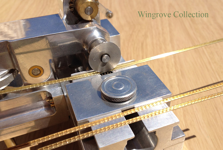
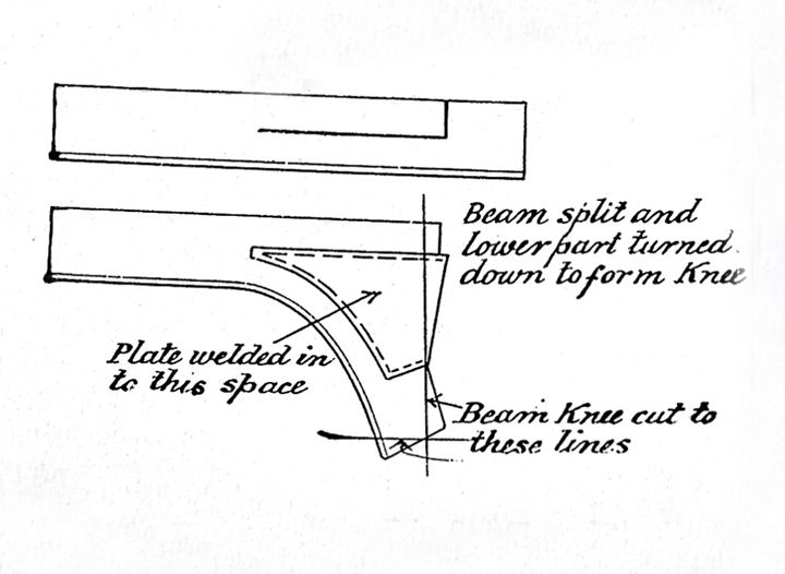
June 2016 Fig-25 - The RHM tool has been modified to produce Bulb Iron, by replacing the spike and hole wheels with a pair of rollers with matching grooves. Fig-26 - The RHM in action - The rollers are brought together with a slight pressure between them so that when the brass strip with the brass wire silver soldered along one edge, is passed between the rollers, they move the wire from one side of the plate to the centre edge of the plate - we now have in brass the Bulb Iron form. This is used for deck beams, Bilge Keelsons and Stringers, more on these when we get to them. Fig-27 - Deck Beams are made from Bulb Iron with an angled bracket at each end, called a Knee. In full size practice the Bulb Iron is cut to length, then split at each end , and the bottom half bent down, as shown and a plate of wrought iron is hammer welded in place to complete the knee. As each frame has slightly different dimensions and angles, it goes with out saying that no two beams are the same. Deck beams are fitted to alternate frames. For the centre section, two beams, one for the main deck, and one for the tween deck. For the model these had to be cut to the correct length, then the knees marked, clipped and bent to the correct angle before silver soldering the additional plate in place at each end. Fig-28 - Introducing the Beam Maker Tool (BMT) - Showing a beam end with a small half round section removed (clipped) with a rat tail file. To design and build a tool that would accommodate beams of different lengths, then cut and bend an identical knee at each end, but to a different angle for each beam - not much in the centre of the hull, but very pronounced as you progress forward and aft with the beams - was a challenge. Another challenge was how to cut (clip) the beam ends for bending. Attempting to clip it as per full size practice was a non starter, as wrought iron is much more malleable than brass. Making a cut in the brass plate and then bending it to form the knee, even after annealing the brass, the brass plate would always split back to the wire. After much trial and a lot of error, I found that a half round section removed with a small round file at the bend point of the knee, for half the depth of the plate, after annealing, would allow the plate to be bent with out splitting. When fully bent in the BMT the half round stretched out to an almost straight line with a slight point at each end. I will give further details of the BMT next month - for those wishing to see more details of the mechanism in the Beam Making Tool, they can be found at < http://www.wworkshop.net/Falls_of_Clyde/Gallery-10.html >

- 281 replies
-
- 9
-
-
- falls of clyde
- tanker
- (and 2 more)
-
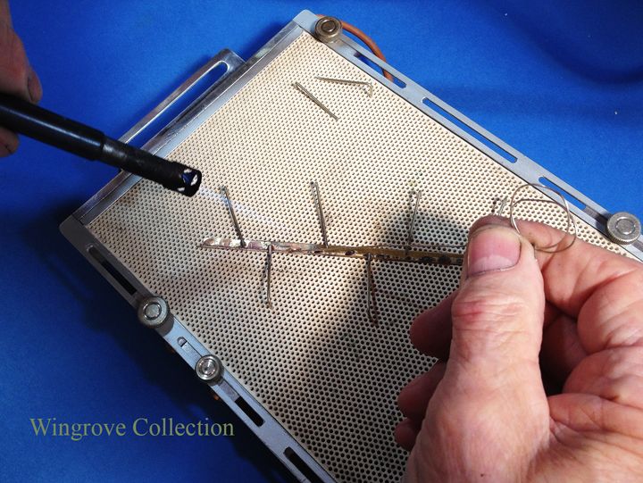
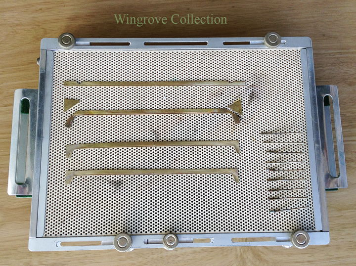
Thank you all for your comments - discussion is what it is all about, it is only when we can get a perspective from another, that we have an opportunity to see where we may improve ourselves. ------------- May - 2016 Fig-21 - The FMJ set up to solder a complete frame together. - The brass setting table was used to set all the fingers in their correct place with the aid of the aluminium half pattern. The fingers were then firmly locked, the brass table was then slid out and the aluminium soldering table slid under the fingers to replace it and locked in place with the two thumb screws at the top. This is provided with a series of holes to take bent wire arms, called Dogs. This is from full size practice, the iron frames are heated to red hot, then bent to a set of pins, and held in place with iron Dogs, it is a very simple and convenient way to hold parts together for soldering. The aluminium plate is needed to replace the brass one for the soft soldering, to avoid any chance of the soft solder fixing parts to the jig. For those not familiar with metal work, soft solder will not stick to aluminium, but will to brass. The angle of the bent frame is first clipped into the small groove on each of the finger tips, the floor is placed on this and the reverse frame placed on that. When all is set fare, the parts are removed and the contact surfaces are tinned with soft solder. As solder will only run on a clean surface, so we make it dirty where we do not want it, (on no account do you want solder on the surface with the rivet heads) and the easiest way of doing that is to run a marker pen along the parts not to be tinned. This with care will prevent the soft solder getting where it is not required. When all the soldering is completed the marker pen ink can be removed with cellulose thinners or similar. Fig-22 - The FMG is made as a live unit, being wired into a resistance soldering unit. When all the contact surfaces of the parts to be assemble have been tinned and fluxed, they are clipped back in place, then it is a simple matter to run around the edge with the carbon tip to heat the solder and complete the joints. The carbon rod has to be in contact with the parts before switching the unit on, and not removed until it is switched off, or sparking will occur that can damage the parts. Fig-23 - Bulb Iron - This illustration shows the Frame, Reverse Frame and Floor in place and Bulb Iron. I mentioned at the start that the hull of an iron ship is built from just three elements, Angle Iron, Flat Plate & Bulb Iron. The first two can be brought off the shelf for a model, as brass angle, and sheet brass, but to reproduce Bulb Iron for a miniature in brass means a little practice in the art of silver soldering. The requirement is a thin strip of brass sheet with a brass wire silver soldered along one edge. Silver solder because the Bulb Iron will be soft soldered to other parts for the deck beams in the model, so the joint has to be good and permanent. Along the edge and not on the edge, as in the finished Bulb Iron, the wire - Bulb - has to be moved from the side to the centre edge of the plate Fig-24 - Silver soldering the wire in place along the edge of the brass plate, Note the use of the wire Dogs to hold the parts in place while being heated with the gas flame and the silver solder run along the joint. The perforated plate is made from ceramic material and is called a 'platinum block' and can be obtained from the jewellery trade suppliers. As can be seen, when used with the wire Dogs, it can be extremely useful in holding parts together under a flame.

- 281 replies
-
- 12
-
-
- falls of clyde
- tanker
- (and 2 more)
-
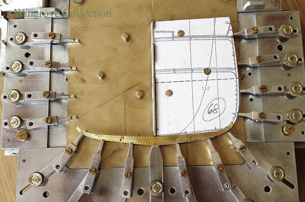
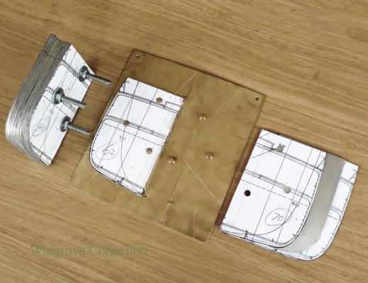
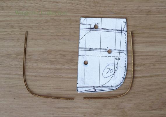
Roughed out with snips, then drilled with the aid of the master patterns for the three drain holes, then assembled with pins through these together with the two patterns and the surplus brass removed on the milling machine. This is an example of the ease of building an iron ship rather than a wooden one. Here 10 floors can be cut as one, then the ends turned - heated and bent - to match each frame. In the wooden world, each would need to be worked individually.
- 281 replies
-
- 3
-
-
- falls of clyde
- tanker
- (and 2 more)
-
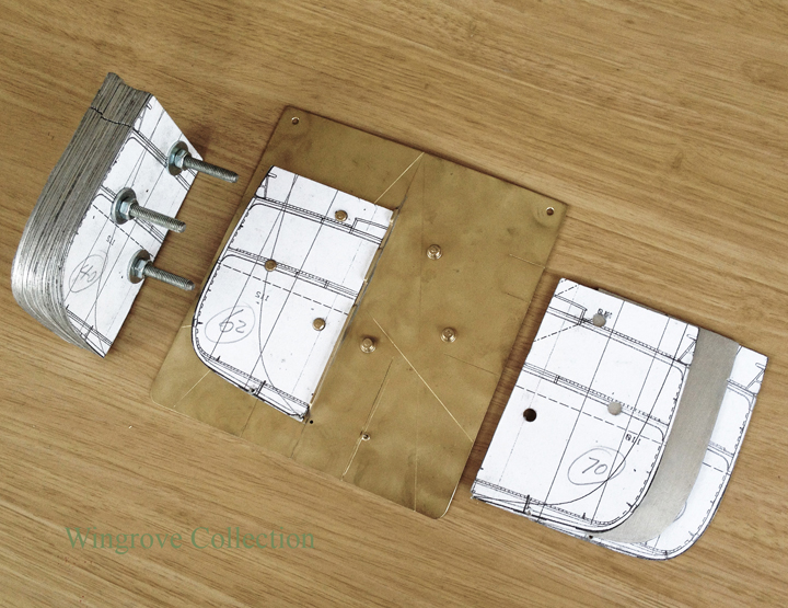
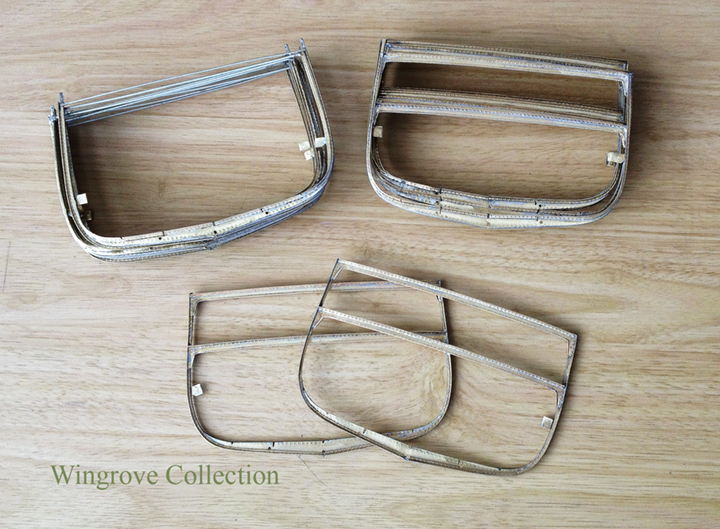
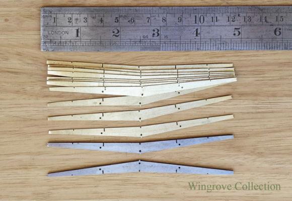
April 2016 Fig-17 - FMJ with Setting plate in place, complete with 2 half frames of angle brass set in the fingers. The top assembly is for setting the deck beams in place, to be covered that later. Fig-18 - Thin brass sheet cut and shaped for the ‘Floor’s, together with steel patterns. At full size, the Floors were cut out of sheet iron with straight edges, then bent to match the particular frames. I first made a pair of gauge plate Floor shapes - patterns - for the widest frame, and used the 3 drain holes to locate with pins, a dozen roughed out brass plates between them. Then machined the brass to match the patterns. I used ‘licence’ here to ease assembly, first by including a small pip at the bottom of each Floor plate, and secondly by providing a small slot to assist in locating the Keelson, Side Keelson, & Bilge Keelsons . When finished none of these are visible. Fig-19 - The RHM being used to proved the Floor with rivet heads, the top row on one side for the reverse frame, the bottom row on the other side for the actual frame angles. Fig-20 - FMJ with a frame master pattern, both angled brass frames in place together with the Floor, bent to match the frames. After the Floor is provided with it’s rivet heads, it is heated and annealed to soften it for bending. Some words on ‘Licence’ - Licence is when you deviate from the original - Ones hears it said that this is an exact replica or the original - in truth one uses ‘Licence’ to create the complete replica, as on a scale of less than a quarter, the very thickness of the materials cannot be scaled. For me I start on the premise that what I create is my artistic representation of the original. I try where possible to follow the practices that produced the original, but in the end if it looks right then, for me, it is right. However I will note from time to time, where gross licence has been used so solve a particular problem - the biggest of course being that the assembly is not held together by rivets, but by soft solder. However if there is an art in this at all, it is to always conceal the licence used, so that the eye is convinced it is looking at what the mind thinks it should be.

- 281 replies
-
- 13
-
-
- falls of clyde
- tanker
- (and 2 more)
-
March 2016 Fig-13 - Setting plate - Two plates were made to fit the FMJ - the setting plate, made from brass with 6 studs, 3 on each side of the centre line, precisely placed to match the 3 holes in each of the aluminium frames patterns. The second plate is made from aluminium as a soldering table, but more on that later. Both plates slide under the fingers of the FMJ and are held in place with 2 knurled screws at the top corners. Fig-14 - Rivet Head Maker - (RHM) - The requirement was to produce something resembling a rivet head of an exact size and precisely placed on the inside of angle brass section of 1.5mm X 1.5mm. The tool consists of two wheels, one with a series of spikes around it’s out side edge, the second with a matching set of fine holes, one for each spike. These are provided with a table and stop, to allow the brass angle to be precisely placed and pass between the 2 wheels, which are set so that each spike will depress a dimple of brass into it’s respective hole as the wheels are rotated. The tool will produce more than 600 dimples - rivet heads - a minute. Several sets of wheels were made to match the different spacing of the rivet heads, to accommodate both the wide spacing for the angled brass - Frame - and the finer spacing for the ships shell plating. A further set of wheels - rollers - were also made for the production of Bulb Iron, but more on that later. All parts were made micro adjustable. The difficult part was to find a way of powering both wheels that also allowed them to be fully adjustable, to control the depth of the pin in the hole - the hight of the rivet head. This was not possible with a geared drive connecting the two wheels, as that is only possible when the gears are fully engaged, otherwise the backlash when not fully engaged - in adjusting the depth - will not mesh the pins with the holes. I overcame this by using rubber ‘O’ rings as the drive between the two wheels, because of the softness of the rubber. This allows for infinite adjustment of the depth of the pin/size of rivet head, while the pin and hole, once set will always be correct relative to each other, no matter how much adjustment is made between the two. The different thickness of the brass between the wheels is a factor in having them adjustable. Fig-15 - The angle brass is first run through the RHM so that both inside faces are provided with a full set of rivet heads. These are then annealed before being bent to exactly match the out side edge of a frame pattern. Fig-16 - The frame and pattern is then placed on one side of the setting plate in the FMJ, and the fingers moved in so that the brass angle sits in the slot provided on each of the finger, that are then locked in place with the knurled locking screws. The pattern is then removed, turned over and provided with the second brass angle frame around it’s out side edge, so that the other side of the frames can also be set and the fingers locked in place. More details showing the construction of these machines can be found on my website: < http://www.wworkshop.net/Falls_of_Clyde/Menu.html > —————
- 281 replies
-
- 12
-
-
- falls of clyde
- tanker
- (and 2 more)
-
A further thought for you Michael - no need to make the elaborate tooling at all for your ships frames. The vital part is the thin half pattern plate - one for each frame - around which is bent the brass angle, frame and reverse frame. Copy the full set of frame cross section onto a piece of card, stick this on a slab or cork, cut this in half at the centre line, then stick it back together again with a thin strip of plate between, so that the half frames patterns can be placed against it. Use holes in the plates, with pins in the block - as I have, to exactly locate the half patterns to the same point. Now anneal the brass angle and bend it around the half pattern, place it on the cork board and press in pins around the edge - remove the half pattern and put pins around the inside - do the same for the other half. Bend the reverse frames to match and soft solder in place. Why did I not think of that in the first place - I am very basic, I need to see something before I can improve it. Good luck - Gerald
- 281 replies
-
- 4
-
-
- falls of clyde
- tanker
- (and 2 more)
-
Thank you Michael - passing on ideas is what it is all about - a thought for you to go with your new proposed project. Use a larger scale, maybe 1/4" to the foot so that the brass angle has some strength in it, annealed brass plating can be bent to shape and has no memory, wood planking, although it can be steamed, and may be the yacht hull will be of much finer lines, but wood still has a memory, that might give problems to the fine brass frames that I have made. You could also steam the wood and match it to the curves of the wood half model, before finally attaching it to the brass frames. Happy modelling - Gerald
- 281 replies
-
- 4
-
-
- falls of clyde
- tanker
- (and 2 more)
-
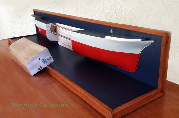
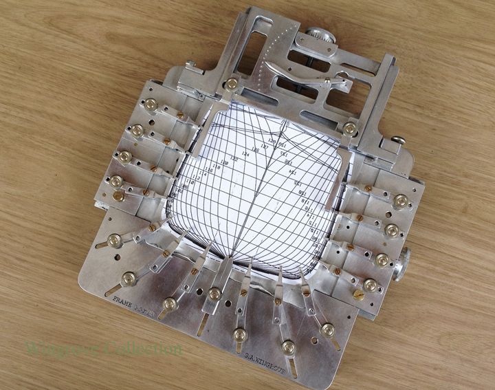
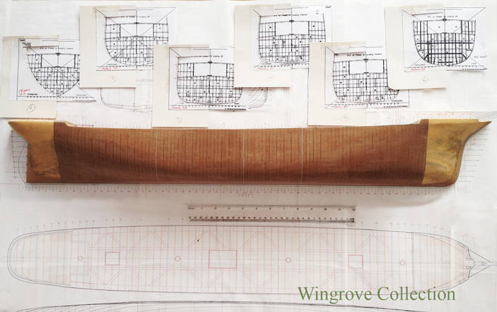
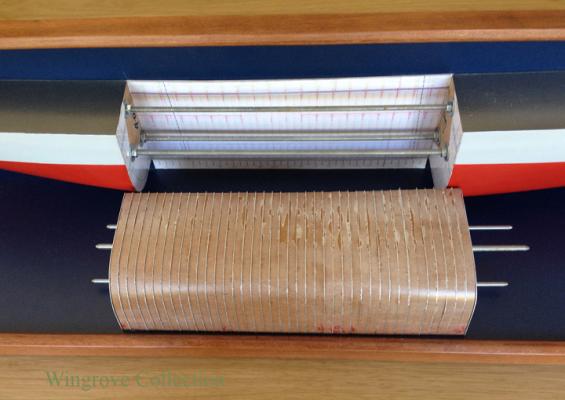
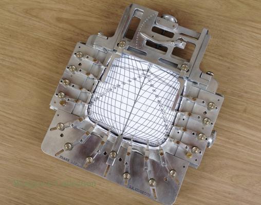
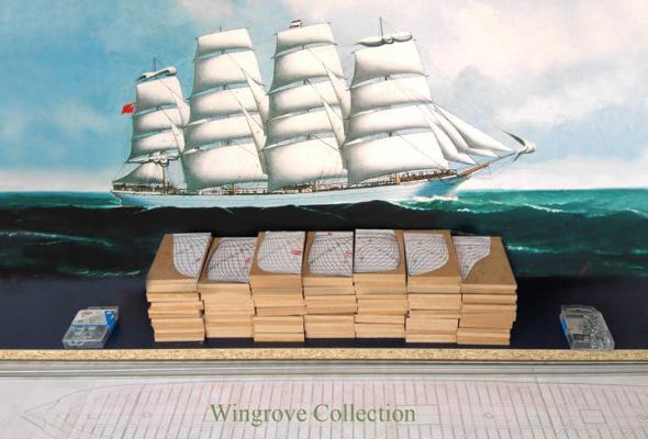
February 2016 Fig-09 - The half model painted and mounted, with the the centre 40 frame patterns removed. - At this stage I could have dumped the fore and aft ends of the hull half pattern, as they were only required to give me the centre sections true shape. However, I liked the look of it, as it started to give me inspiration for what I was about with the centre section of the ship, here she was in all her glory. So I decided to paint it up, mount it on a stand and keep it in view while working up the actual model. One can build dead-pan, like building by numbers, when all about you are pieces of wood and metal, until the project is completed, when you finally see what you have built, which is usually a dead-pan model. For me I have to have the subject in my head at all times, constantly being reminded by drawings & photos of the complete subject, so that I am substituting an imaginary part with a real part every time I complete a section however small. In this way I hope to make a miniature of the subject, rather than a model, in that it captures the character of the original, as seen through the wrong end of a telescope. Some models will always appear as models however you photograph them, others can trick the mind, in that you ask yourself when you view the photo, is this a model, or the real thing, that is when you had captured the character of the subject. This for me is only possible when I have fully researched the subject, and I constantly keep in view my research material. The figure at the break of the foc'sl is Jock the riveter, carved in nickel silver to the same scale as the model - always useful to have a scale figure around to double check what you are about - we will see him again from time to time. Fig-10 - The centre 40 frame patterns bolted together, with a thin plate of aluminium between each. - The MDF quarter inch thick frame patterns are of no use as they are, as each side of each plate will have a different shape, very minute in the centre, but more pronounced as one moves out fore and aft. For them to serve their purpose, I needed a very thin copy of each, so slipped in a drilled sheet of thin aluminium between each, bolted the pack together again and filed each to match the MDF shapes. The reason for this is that each half pattern has to provide a right and left side for each frame. the quarter inch thick MDF plate cannot do this. Fig-11 - The 40 MDF frame patterns with the 40 aluminium patterns removed. - Thus I now had a pack of thin half patterns for the 40 frames, that can be used to give two half frame shapes that will be identical, one for each side of the ships hull. Fig-12 - The frame making jig. (FMJ) - I knew nothing about iron ship building when I started the project, so read up every book that I could lay hands on on the subject. Then knowing every stage for building a full size ship, imagined each of those stages for a miniature, and the tools required to accomplish that end - then made the tools. The complete tool kit was designed and made from scratch over a 9 week period of brain storming, before starting the model. Details of the construction of each tool can be found on my web site. With some minor modifications that I will mention when we get to those stages, all of the tools worked out as planed. FMJ - The first requirement is to be able to precisely hold 4 sections of brass angle and a brass plate in one place, such that they can be soft soldered together to form a ships frame, then to exactly locate and solder in place the two deck beams. The third requirement is to be able to do that 40 times, with a slightly different shape for each frames. And should I wish to build a complete hull, to accommodate all 129 frames. My solution was a set of infinitely adjustable fingers, the tips of which are provided with a small flat and a slot to accommodate angled brass section, these being made from aluminium, to facilitate soft soldering. The basic ships frame, for the Falls of Clyde, is made up of 5 parts, 4 of which are angle iron. Two of these are bent to shape, such that a flat is on the out side, one for each side. A second pair, called reverse frames, are bent to match these, but with the flat on the inside and both are riveted together for most of their length. The fifth element is a flat plate at the bottom, riveted between the frame and reverse frame and is called the ‘Floor’

- 281 replies
-
- 14
-
-
- falls of clyde
- tanker
- (and 2 more)
-
Thank you Michaell, always good to hear from from the other side.
- 281 replies
-
- 1
-
-
- falls of clyde
- tanker
- (and 2 more)
-
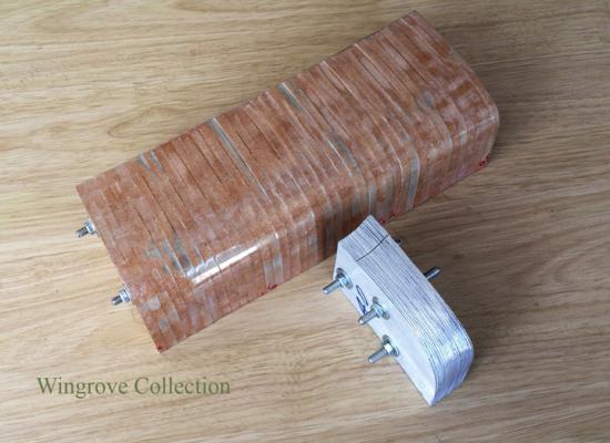
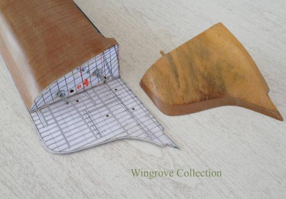
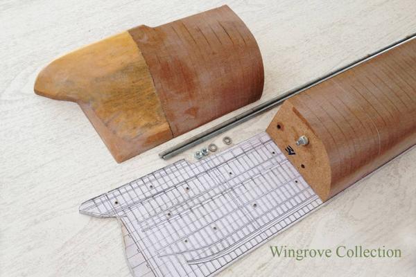
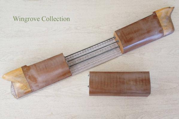
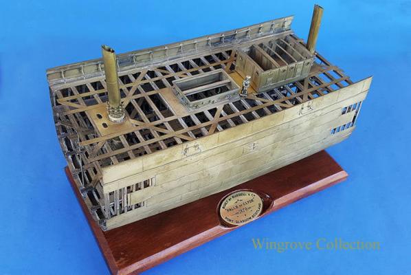
Jan-2016 Fig-05 This is the aft end of the half model with the stern end block removed to show the ends of the two screwed rods that hold it all together. Fig-06 Showing the forward end of the half model, with the stem block removed to show the threaded rods. Fig-07 Showing the third rod in the centre of the half model. Fig-08 Showing the half model with the centre 40 frame patterns removed, these are the patterns to be used for making this particular model of the centre section of the Falls of Clyde. On plans and data for iron and steel ships - One of the advantages of building models of iron and steel ships, is that they are all built in the same way to the minutest detail and to the same rules, those built in the UK, to the rules set out by Lloyds of London who insured the ships. I have been given to understand that there were similar rules and standards set in the USA and other countries. The owner would set out the capacity of the ship to be built together with certain other details, after which the builder would consult Lloyds specifications as to how to proceed with the construction. For an iron ship of a given tonnage, the distance between the frames, the thickness of the metal for those frames and the thickness of the shell plating for any given place, will all be specified by the insurer. As also the diameter of all the rivets and the spacing there-of for every part. If the mast is of this hight, then the diameter at a given place and the thickness of the plating at that place will all be listed in the insurers specification. Every detail of the construction has to comply with the insurers specification, to obtain a certificate upon which the rates of insurance can be calculated before the ship can put to sea. For the model maker this can make life easy, for if you can locate the specification for the country in questions, you have all your questions answered as to how the ship was built. This will include such things as how the shell plating was applied, not as I have seen on some models, with a butt joint at every alternate strake of plating up the side of the ship, but at every 5th strake of shell plating. To make the plating like a tiled floor or a brick wall would weaken the structure, for it is the shell plating of an iron or steel ship, that is it’s strength. As also the deck planking, where I have seen on many models with alternative planks butt jointed across a deck. It might look pretty but check photos of a real deck, and you will see at least 5 or 6 planks between each butt joint. This is very basic information that can be gleaned from old photos, however there are books available with a lot of this information in. The first one of these that I came across with Harold Underhill’s ‘Masting and Rigging’ - as with the hull of a ship, so with the rigging. A hull of a given tonnage will have masts and yards of a given length and the rigging from any part of these will be of a stated size, whether it be hemp or wire, scale this down and there is no excuse for having running rigging with a scale thickness of 6 inches in diameter, it never was so. For the iron and steel hull I can recommend ‘The Modern Practice of Shipbuilding in iron and steel’ by Samuel J.P. Thearle, in two Volumes, one of text the other of detailed drawings. Also ‘Ship Construction and Calculations’ by George Nicol, with many illustrations. Both of these date from the last period of sail and the start of the period of the steam ship. It may be difficult to find copies to purchase, but central libraries, such as the British Library in London, have copies, that may be borrowed through local town hall libraries, which is how I got access to them.

- 281 replies
-
- 15
-
-
- falls of clyde
- tanker
- (and 2 more)
-
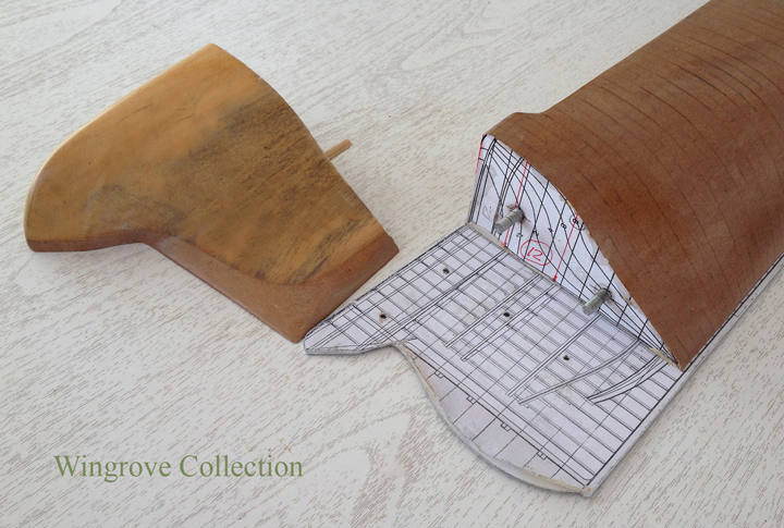
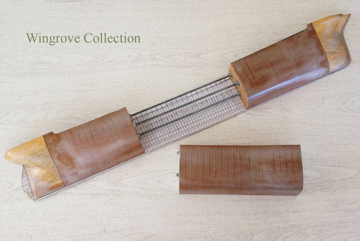
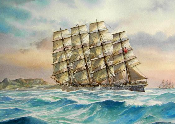
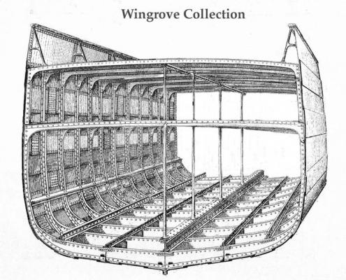
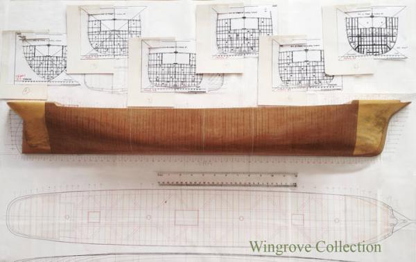
Substitute brass for iron where ever you see it, as the model is built in brass, but the original is in iron, as also the look of the model will be when finished. To build in iron is very simple, unlike timber, as the materials are already of the correct basic dimensions, thickness and shape, and there are only 3 of them, angle iron, plate, and bulb iron. The complications come in the working of them - with timber it is an adze, saw and boring tool for basics, and each piece is worked on in every dimension. With iron it is a blacksmiths shop and a wealth of heavy machinery to bend and form the 3 basic materials. On my web site at < http://www.wworkshop.net/Falls_of_Clyde/Menu.html > is/will be - the complete ‘Build’ of this model project, but from the viewpoint of the tool making. Here I will create a ‘Build Log’ of the actual building of the model’s - two down and one to go, the last being a fully rigged waterline model of the FofC, still yet to be made. I will aim to do this with 4 photos a month and a brief description of what is going on. At the end of the month I will answer any questions and move to the next stage. In this way I would hope that ‘we’ can cover more fully what you as model makers wish to know to follow in these footsteps, with out repeating what has gone before on my web site. The subject - The Falls of Clyde, is a 4 masted sailing ship of 1807 tons gross, built by Russells & Co., Port Glasgow in 1878. After 324 voyages under sail, with a first class reputation as a fast and friendly ship, (later rigged as a barque), now lying forlorn and neglected in Honolulu awaiting a fate, that has already being spoken of, as being sunk as a divers wreck, if money is not very soon forthcoming to get her into dry-dock as a start to a new full restoration. The other option that I have been promoting for the last 10 years, is to get her back on the Clyde in Scotland, where the Clyde Maritime Trust have the crew and knowhow to bring the old girl back to life, to spend her days along side the Glenlee, a 3 masted barque of the same period, that they have just recently restored in all her glory. Anyone wishing to contribute to this please drop a note to Frank Brown <Frank.Brown@thetallship.com> Plans - There are no fully detailed plans of the ship that I know of being available. There are a couple of people working on producing a set but as yet there is still much work to be done. There is/or was, available a copy of the original side view of the hull, together with a centre cross section, plus a several smaller detailed drawings of the loading ports, 4 in the stem and two others on each side towards the midships and some other odds and ends. These were copies from the original Russell & Co. 1878 ships plans, I obtained mine 30 years ago, from I cannot remember where. These I digitised and expanded adding data from the actual ship, that I have visited 4 time, the first in 1970, shortly after her last full restoration, the last in 2005, when I created eruptions with those responsible who had let her get to the sorry state that I found her in. However some of my developed cross sections seems to have been some way out as to the hull shape, for just as I was about to start the half model I was provided with copy of cross section of the hull made at the time she was converted into a tanker, in 1907. It was these that I then used for my final shape. For those wishing to take this further, unless you wish to undertake a lot of research or await the coming of a set of plane, how-long-is-a-piece-of-string, then better to take a look at something like the Balclutha, still with us in San Francisco, in excellent condition, with a full - very full, set of plans on line at: < https://commons.wikimedia.org/wiki/File:Balclutha_Deck_Plans-_Poop_Deck,_Forecastle_Deck,_Main_Deck,_Main_Deck_Structural,_Tween_Deck,_Tween_Deck_Structural_-_Ship_BALCLUTHA,_2905_Hyde_Street_Pier,_HAER_CAL,38-SANFRA,200-_(sheet_4_of_69).png#filehistory > I will have more to say about this anon - Now to the start and the photos. Fig-01, - Here we see the Falls of Clyde heading for Cape Town on a voyage from Dundee to Rangoon in February 1881 in all of her original glory and depicting the period of my models of her. The painting, an original commission of mine, is by David C. Bell B.A.hon. - for those interested in wooden walls, here you have a friend indeed, an authority on Nelsons ships - check out: < http://www.themarineandwildlifestudio.com/maritime.php > Fig-02, - Showing the inspiration for the iron hull centre section model, the main subject of this Build Log. Fig-03, - The half model - In starting out I had hoped to avoid making a half model, being only interested in recreating the centre 40 frames. My ideas was to work directly from the plans that I had created, taking the lines directly from those. The hull of the FofC are almost those of a late clipper, with not a straight line on them, meaning that no two frames are the same, also meaning that the difference between the size and shape of the centre dozen or so is so minute on a scale to 1/96th that we are down to less than the thickness of a pencil line between them. So to make a half model - To carve a solid model, as is the standard practice, full size and for miniatures, meant having to mark out the individual frames, then transfer this information to the ‘loft floor’ from which the frames could then be formed to match - but then we are back to the thickness of a pencil line and I do not trust my judgement to that fineness. The frames are 2 feet apart - scale size .25” - so I figured that by making the half model with plates of 1/4 thick MDF board, I would have one plate for each frame. By bolting together as many as I could, with a block of wood at each end, and carving this to exactly match the hull drawings, using card templates to double check, would solve all of the problems. Why not use the card templates for the frame shapes? - because one only needs a half dozen side templates, together with several longitudinal ones to create a full half model - it is joining up dots to a free flowing line from a given point to a given point. When looked at, at 1/4” intervals, they look like straight lines, but as a set formed together, they each have a flow. The MDF plates were cut square and accurately and provided with a datum point common to them all. Each plate was then given a copy of it’s cross section from the original drawings with as much information on it as possible and matched to the datum point. These were then placed in a simple drill jig and provided with two hole, with a centre section plates being provided with 3, all to take long threaded rods. The position, as with the width of the two end blocks being determined by the size of the washers & nuts necessary to hold them all together. As the frame plates reduce in size fore and aft, so the space available to hide a nut and washer inside becomes less and less. Each plate was then jig sawed to shape leaving about an 1/8th inch clear from the paper pattern, to take care of any inaccuracy in the drawings. The final shape being determined by a pleasing line of sight, as was the practice full size. This assembly was then wood screwed to a back board of 3/4” melamine covered chip board, cut out to match the side profile of the hull. The whole then carved to shape, with chisels, gouges, sanding discs, files, with fine paper to finish. Fig-04 The basic half model, also showing in the background 6 of the hull cross section drawings, drafted at the time the FofC was converted into a bulk oil tanker in 1907. These were used to correct my original drawings. Note that there are three white lines showing between the plates, that are in fact very thin plates of aluminium. They indicate the extent of my 40 frames, together with the centre frames - more about this as we proceed.
- 281 replies
-
- 20
-
-
- falls of clyde
- tanker
- (and 2 more)
-
Many thanks all, I will take a look at thinning down and reordering my collection of photos for a Scratch Build Project here. My own Current Project will run to about 400 photos (and end in June next year) with a focus on the tool making. Now that it is completed - the model was finished last week end, I can reorder the photo collection as a Ship Building Project that hopefully might encourage a few others to replicate ship building in metal, as so many of you do in wood. Watch this space.
-
You have no heading for iron/steel ship models - if of interest to the other model makers, I would be pleased to put up a truncated version of the 'Current Project' on my own web site at: http://www.wworkshop.net/Falls_of_Clyde/Menu.html I can leave out the tool making, and take the viewer through a dozen or so photos, enough to show the process and progress of the construction. I see nothing similar in your splendid web site. With respect, Gerald
- 80 replies
-
- 11
-
-
Thank you for the link zoly99sask that is truly impressive, it makes one humble to think how far some of us have yet to go to active the ultimate - but very good to see just what can be done with skill and time when you put your mind to it. It is a very impressive web site in general and well worth a detailed look at all the models, there is much to be learnt there.
-
Bilge Pumps 1870/80
GAW replied to GAW's topic in Discussion for a Ship's Deck Furniture, Guns, boats and other Fittings
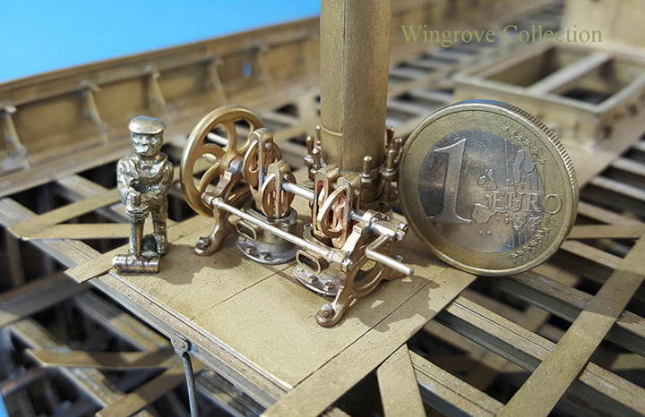
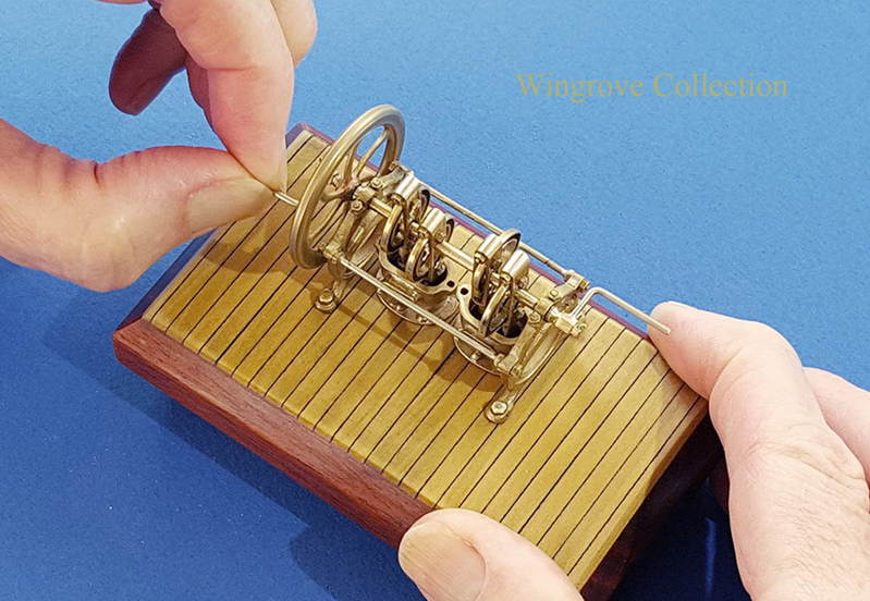
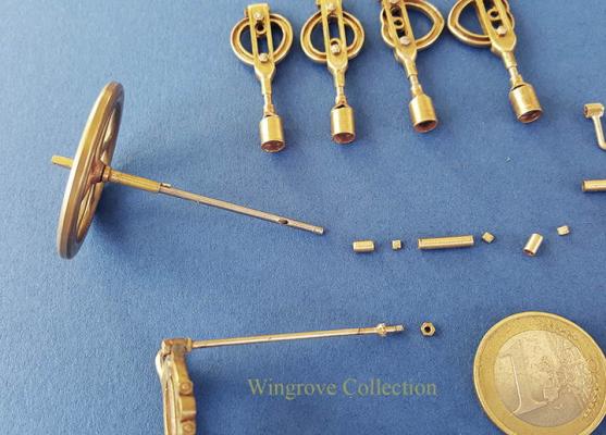
Working from the original Wallace & Crawford Patent drawings the recreated Falls of Clyde Bilge Pumps in 1/8" & 1/4" to foot scale, the former fitted to the model, the latter created as a working mechanism. All hand made excepting the larger cams, which were machined on a friends CNC machine - I have my limitations - A very interesting mechanism for 1869 - how did they make those cams?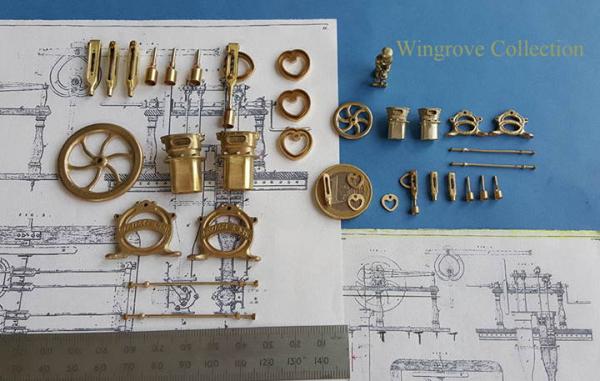


-
Bilge Pumps 1870/80
GAW replied to GAW's topic in Discussion for a Ship's Deck Furniture, Guns, boats and other Fittings
No name as yet druxey, just Patent No.2736, 1869 in the name of Wallace & Crawford - I am still awaiting the text that should be with the drawings, as from what I can see it cannot work as is. There is no crank shaft as such, just a shaft with 4 cams keyed to it, that lift the piston arms, but it appears to be left to gravity to bring the arms down, which does not seem correct, although there is a second mechanism described that could work, but does not fit the main drawings. However all should be revealed when I get the text - I feel I am getting closer, which is just as well as the model is now only awaiting the bilge pumps to complete it. Thank you Mahuna- that was nine weeks of brain storming - the actual model however has taken 11 months, at about 6 hours a day, although a lot of that time was taken up with doing things twice and three times over working through the problems, which is the fun part of model making. All is revealed at: http://www.wworkshop.net/Falls_of_Clyde/Menu.html at the finish, there should be almost 400 build photo. -
Bilge Pumps 1870/80
GAW replied to GAW's topic in Discussion for a Ship's Deck Furniture, Guns, boats and other Fittings
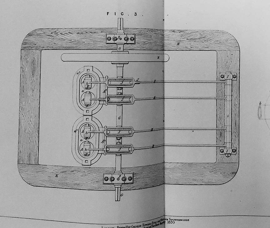
I have now located the patent drawings for a Bilge Pump, designed and built by R.C.Wallace & Son, of the right date and configuration to fit the openings in the deck plating of the Falls of Clyde. The copy of the drawings are on order, but I have a snap shot here from the original book of the top view. Should any one know of illustrations/photos of such a Bilge Pump design, I would be pleased to hear from them - 4 inline cylinders with a single flywheel, no A frame, the crank being mounted on the fife rails.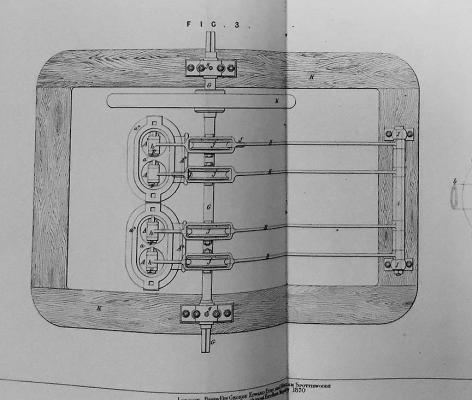
-
In answer to Bill - I am both an impressionist - for what I make can only be my artist impression of what I see - and also a realist - in that I know my limitations, and that of the materials that I have to use.