HOLIDAY DONATION DRIVE - SUPPORT MSW - DO YOUR PART TO KEEP THIS GREAT FORUM GOING! (Only 24 donations so far out of 49,000 members - C'mon guys!)
×

ggrieco
-
Posts
276 -
Joined
-
Last visited
Content Type
Profiles
Forums
Gallery
Events
Everything posted by ggrieco
-
 With the end of the semester approaching, I wasn't able to get a lot done this week. i was able to do a little more work on the engine. I rebuilt the rockers to the simpler configuration and finished the packing for the valves and almost finished the supports for the poppet levers. I started to blacken the engine but it didn't take in some spots so next week I'll go over it once again.
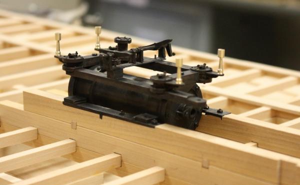
- 701 replies
-
- 26
-

-
Whoops, you got back to me before I edited my post. I think you are correct. Your reasoning is very convincing.
-
Thanks for the info Cathead, It does look like Pittsburgh did provide a lot to the industry as well as Cincinatti, Ohio and Louisville, Kentucky. We do know that a replacement paddle wheel for Heroine was cast in theJefferson foundry in Louisville, Kentucky. One of Heroine's shaft couplings was marked Schoenberger for Pennsylvanian foundry man Peter Schoenberger. I think you are correct that most of the iron work, if not all of it probably came from foundries along the Ohio River and were purpose built for the steamboat. I'm sure the simple engine was a design that was fairly common and easily adapted and possibly specifically built for Heroine or reused from an earlier steamboat. There is such a hodgepodge of different design element on all the parts that it appears that it was all thrown together from spare parts.
-
Thanks Cathead, We've been looking for evidence of the reuse of stationary engines on steamboats but I hadn't considered the idea that they have been reused in the opposite direction. We know Heroine's engine was salvaged shortly after running onto the snag but I don't know where it eventually ended up.
-
Hello Mark, Heroine's boilers probably had a large mud drum connected laterally under her boiler tubes. It would have caught much of the silt coming into the boilers but there would have still been a lot of build-up in the tubes. Periodically, the boilers would have to be shut down and cleaned out. We have found no evidence of a filtration system in the feed water line. Although just a few components of Heroine's feed water system were recovered, it was most likely a simple pump to a shroud around the steam exhaust that acted as a pre-heater. Then the water was pumped directly through a check valve and then the boilers. The silt was so bad that a filtration system would probably be overwhelmed. It appears that they were just relying on the volume on the boiler tubes getting them to the next cleaning.
-
That is a possibility, these vessels evolved so quickly in the first couple of decades that designing a whole new power plant would be less likely that adapting what they already had. Maybe these early flywheel engines were repurposed stationary engines and as the engines matured, they adopted more complex systems to control the valves, giving them more controllability to start, stop and reverse more efficiently and eliminating the need for the flywheels.
-
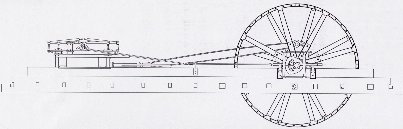
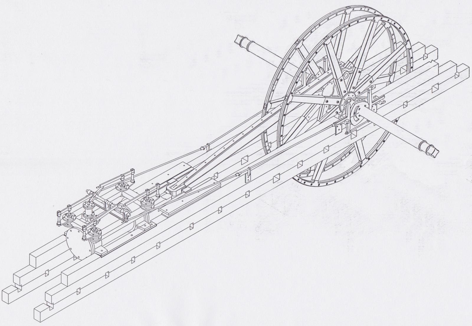
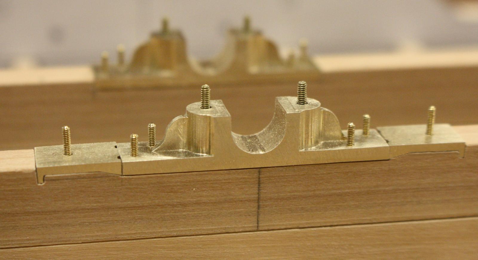
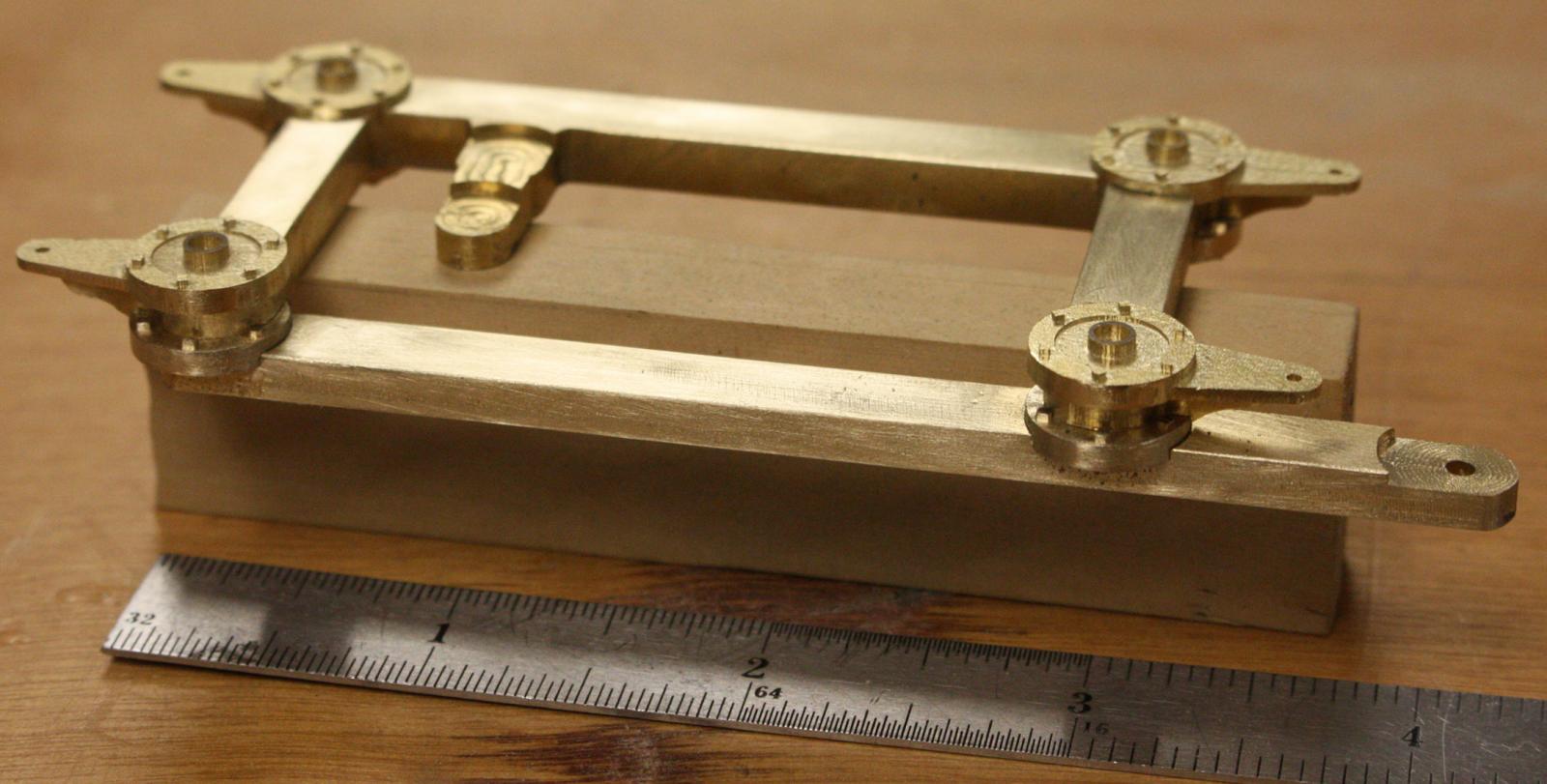
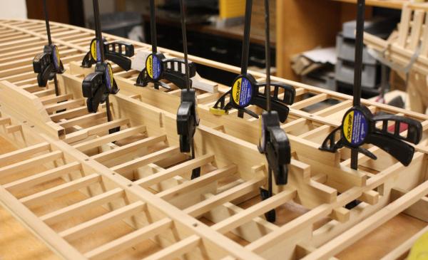
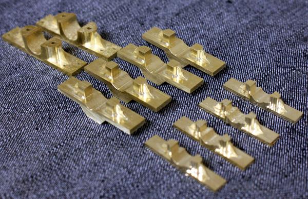
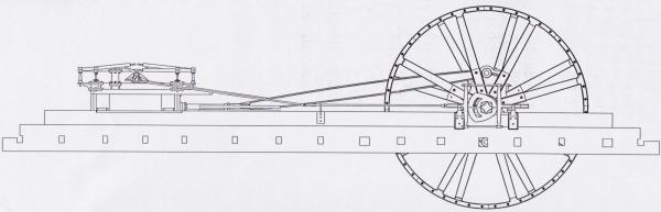
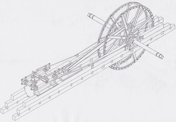
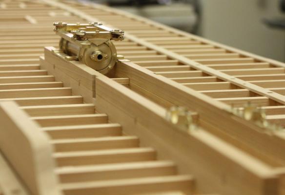
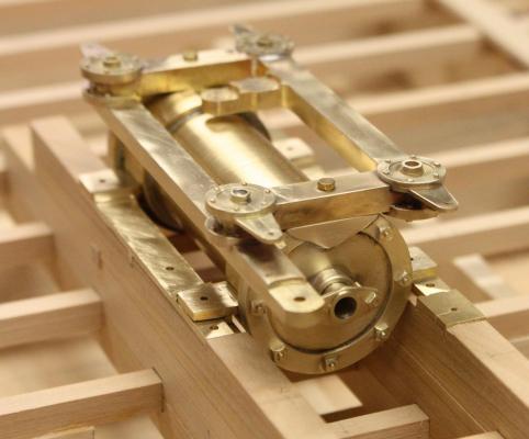
I decided to take a break from the soldering this week and finish up the hull planking and cylinder timbers on the second hull. Some of the machinery requires that some of the deck planking is in place and I'm hoping to be able to take care of that this next week. The cylinder timbers notched for the frames and the wedges that position the top timber. Cylinder timbers in place. The mill continued to make bearings while I completed the hull. From left to right are the Inboard flywheel shaft bearings, the outboard flywheel shaft bearings, and the outboard paddlewheel bearings. I still need to complete the inboard paddlewheel bearings and the bronze sleeves for all the bearings. Last week I mentioned the steam wiper arrangement and realized I didn't have it correct. In order to utilize the full stroke/ cut-off cam arrangement that was common, both cams would have to be on the same side of the engine. We know Heroine had two cams, one on either side of the flywheel. Unfortunately, we have no other example of a riverboat engine with a centerline engine and flywheel. This arrangement is more like a stationary engine that you would find in a factory. It seems that this engine probably had a very simple valve assembly with just two full stroke cams. The momemtum from the flywheel would have smoothed out the motion at the ends of the stroke. Starting and reversing could have been accomplished just by lifting the proper levers by hand. I could be wrong about this but it seems the most likely arrangement. If anyone has ideas about this I would love to hear them. Profile of engine and flywheel. Engine half-way through a stroke. Port cam is fully forward opening forward exhaust valve, Starboard cam is fully aft opening aft steam valve.

- 701 replies
-
- 21
-
-
Thanks Cathead,Kurt and druxey, Cathead you are correct. If you get a chance, take a look at some of Dr. Kevin Crisman's articles on the Heroine, he has found an amazing amount of information on the vessel and its last voyage. Glenn
-
Thanks Carl, I'll give this a try. It sounds like it should get rid of the annoying bright patches on the brass. Glenn
-
Thanks everybody, Your kind words have made my Thanksgiving! Hello Bob, great question! I have been going over so many drawings trying to decipher the engineering and how it applies to our early engine but, I still have many questions. Most of the examples I see are decades later than Heroine's and a little more advanced. Also, they are usually paired engines and we have the single centerline engine. On most engines there are two rocker shafts. The two wipers are attached so that they can move independantly on one shaft and the second shaft is linked directly to the exhaust wiper. Typically, there are two cams, a cut off cam and a full stroke cam. The valve linkages are engineered in a way that the reach rod from the full stroke cam can be attached to both shafts controlling both wipers or attached just to the exhaust wiper while the reach rod from the cut off cam engages the steam wiper. When the full stroke cam engages both shafts in does so in a way that they reciprocate equally in opposite directions. When the cut off cam is engaged, the wipers opperate independantly allowing beter control of the introduction of steam into the cylinder. For Heroine, we only have a full stroke cam on the port side of the engine and we know that there was a second cam on the starboard side. It is possible that the engine just used two full stroke cams operating both wipers but this would not have been a very efficient way to do it. (Although little about Heroine was efficient) In the model, I have built it this way but have left the wiper arrangement removeable in case I want to add the cut off cam arrangement. So far, Heroine is the only example of a single centerline engine with flywheel that I've seen and I think we still have a lot to discover about it. I was hoping some steamboat enthusiast out there might have an idea that they could send along. I hope my description was helpfull. If I find any new info that affects Heroine's engine I'll be sure to post it. Glenn
-
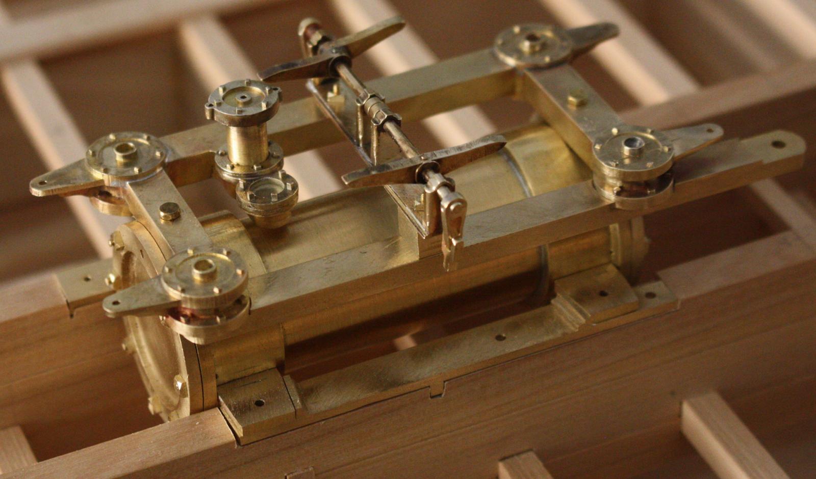
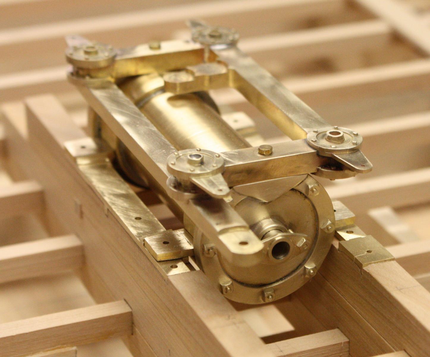
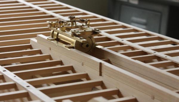
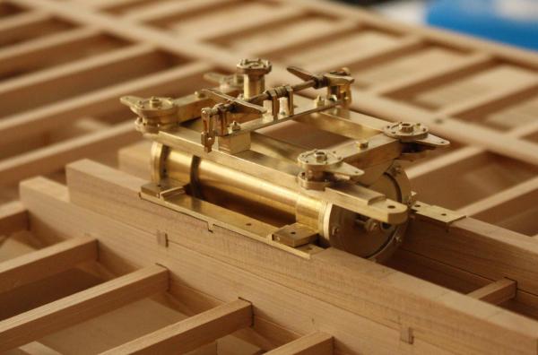
I was just able to finish the steam wipers and the throttle housing before the holiday break. I played around a little with the lighting and exposure time and think the photos turned out a little better. I think the secret is as little light as possible when photographing brass.


- 701 replies
-
- 33
-
-
Kancabas cargo boat by mhmtyrl - FINISHED
ggrieco replied to mhmtyrl's topic in - Build logs for subjects built 1501 - 1750
Merhaba Mehmet! I love the weathering on your model. Very authentic! Glenn- 32 replies
-
- 2
-
-
- kancabas
- cargo ship
- (and 1 more)
-
Thanks everybody, Yes Cathead, l feel the same way about the size of the engine compared to the actual size of the vessel. I read somewhere that even a well maintained high pressure engine on one of these steamers ran at less than 4 percent efficiency. What the engine lacked in size, the boilers made up for. The fireman must have really had his hands full.
-
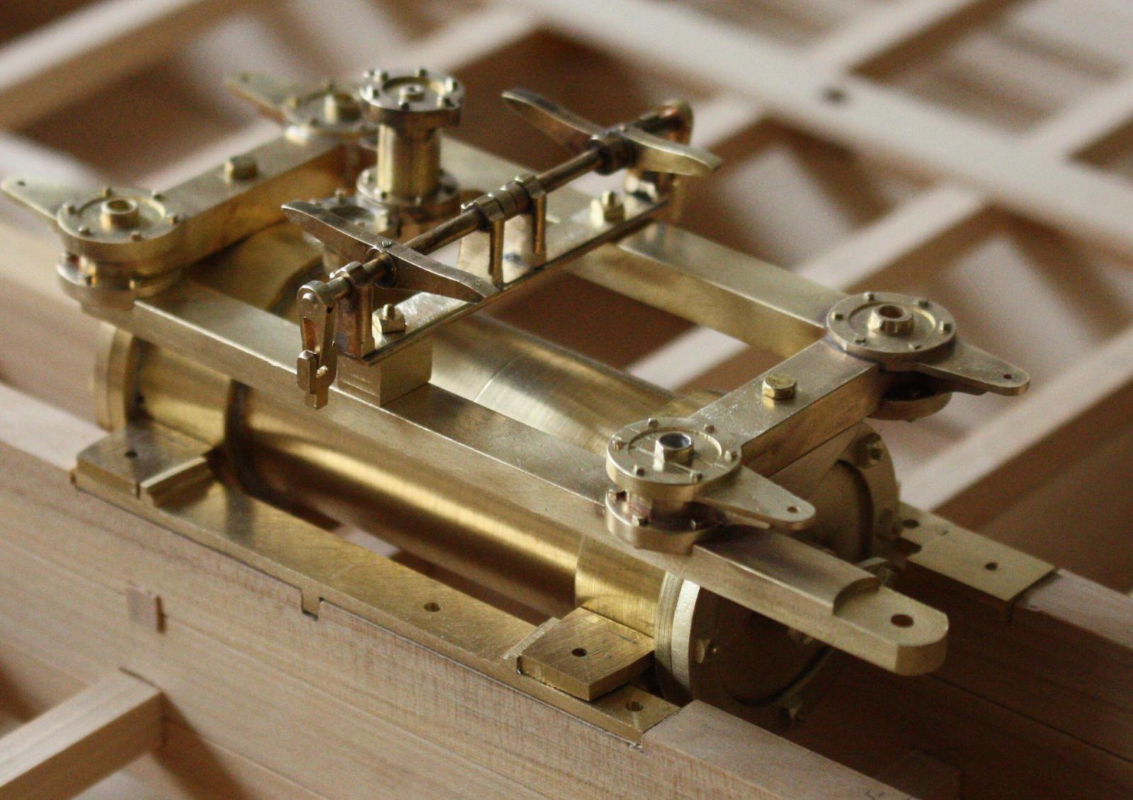
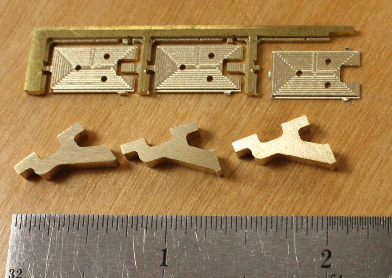
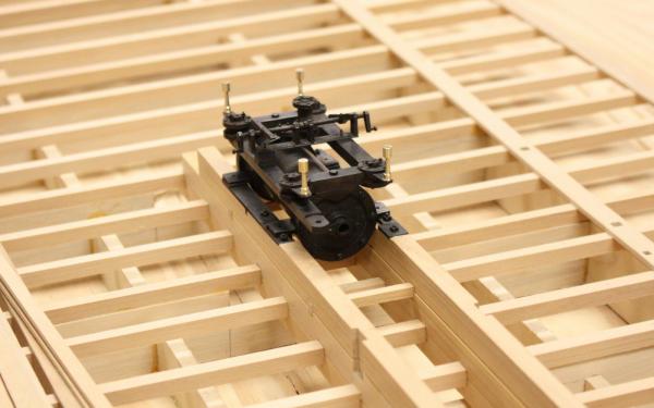
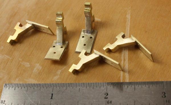
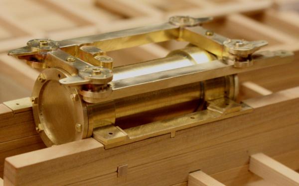
The 8 year old computer that runs my mill gave out early in the week. It has made a lot of parts in the last 2 years and was well worth the $28 that I paid for it from Ebay. I just paid $50 for a replacement and hope it performs as well. I was only able to make a handfull of parts but, I finally got the time to start assembling the engine. Parts for the cam frame supports. Completed cam frame supports. The engine minus the rods levers and wipers for the poppet valves. I have never been able to photograph brass well. The suface shows every scuff and rub mark. Blackening will give it a much more even appearance. Steam wipers and supports.


- 701 replies
-
- 33
-
-
Hello Greg, It's wonderful to be here and a bit humbling as well. I am in awe of the beautiful models that I've seen on this site. I just wish I had more time to explore! Our program could really use your talents and the talents of so many modelers on this site. Yes, the mill is cnc. Then mill lends itself well to a project like this with so much machinery.
-
Hello Cathead, I hope you don't mind if I follow your built and borrow some ideas from you. We have pretty good information on most of the hull up to the deck. Almost nothing exists above that but, we can guess at some of it from post holes. Dr. Kevin Crisman has done a lot of research and has come up with a beautiful reconstruction of how the vessel looked. He has a profile but he is still working on an internal profile and the details of the upper works. You can download a .pdf of our IJNA article on the machinery at https://tamu.academia.edu/GlennGrieco Just click on Kevin's name on the page an it will take you to several of Kevin's articles on the Heroine and several other projects that he worked on. I have also done a number of models of different aspects of the wreck that you can find at http://nautarch.tamu.edu/model/report5/ Most of the constuction of the lower hull was down from hundreds of pages of field notes from the excavation and we don't have compete drawings yet. If there are specific details that you are interested in, let me know and I'll try to find the specifics for you. I'm happy to hear from you and I look forward to following your build. Cheers, Glenn
-
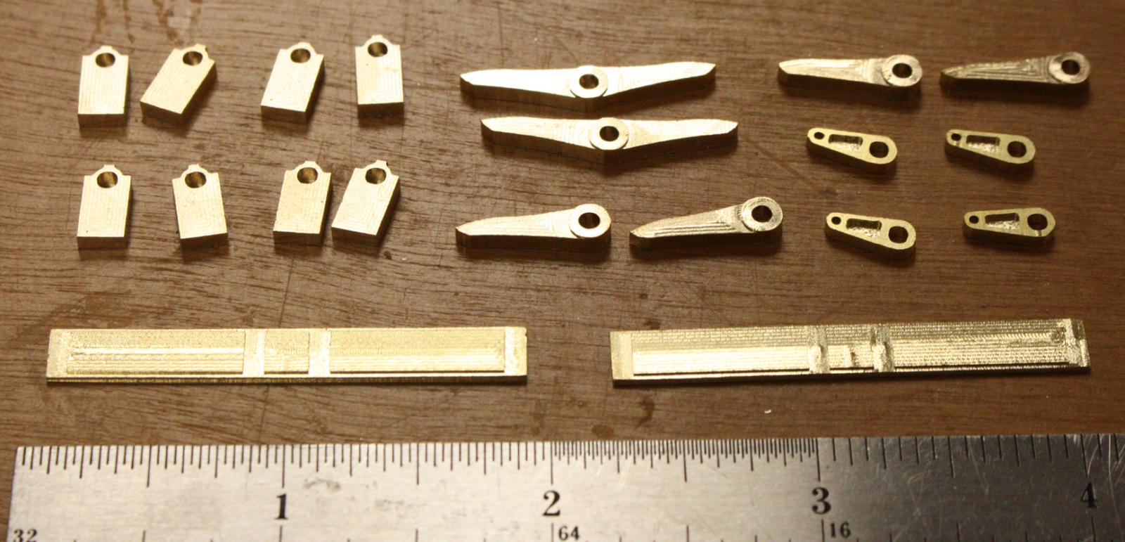
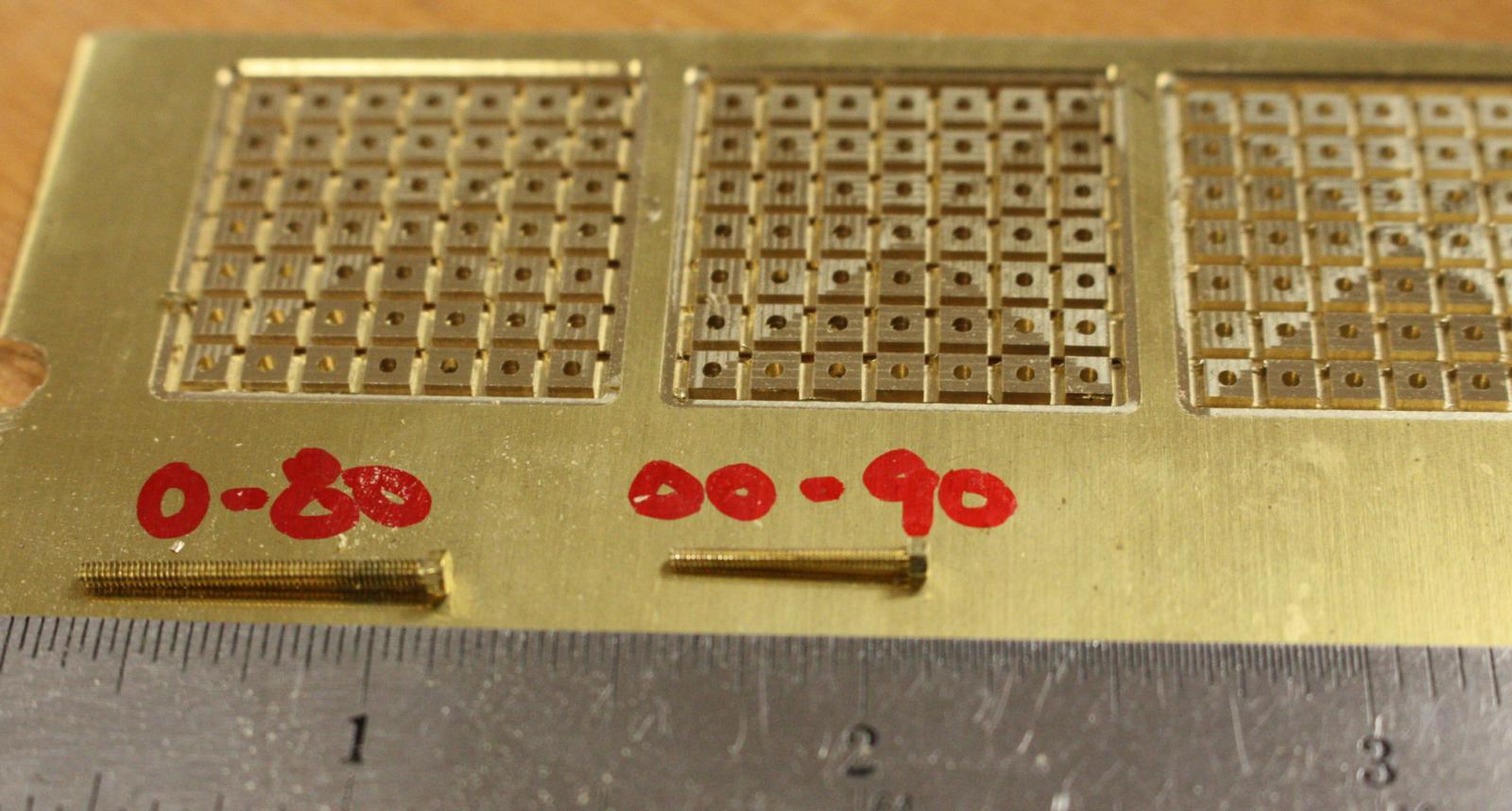
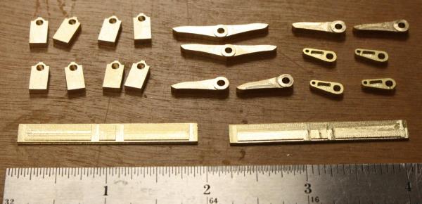
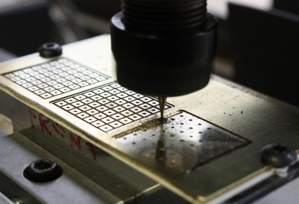
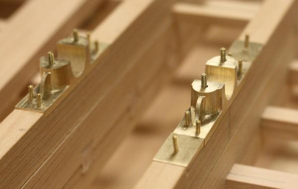
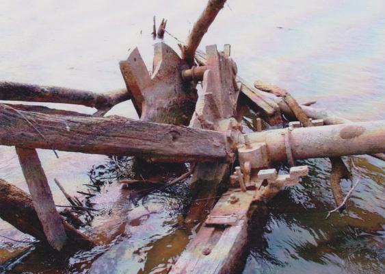
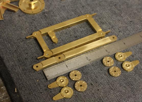
I finally have most of the machinery parts machined. Time to have some fun putting everything together. Each model requires over 250 nuts and bolts just for the machinery. The nuts and bolt heads range in size from 1 1/2 to 2 1/2 inches. I found that 0-80 and 00-90 screws work for most of the bolts on Heroine but could only find screws with hex heads. Heroine only used square headed fasteners. I milled the nuts in three different sizes (scale 2 1/2 shown in photo) The holes were milled slightly undersized and drilled and tapped to the proper thread. Completed flywheel bearings notched into the cylinder timbers. Starboard flywheel bearing as it appeared before excavation. The parts that make up the valves for Heroine's engine. Valves ready to be soldered.

- 701 replies
-
- 26
-
-
Happy Birthday and all the best for yours as well! We're expecting a cool and rainy day today - just as I like it. I've decided to take the day off and be lazy. I hope your day and weekend are wonderful as well! Cheers Glenn
-
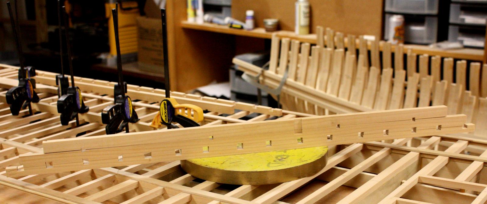
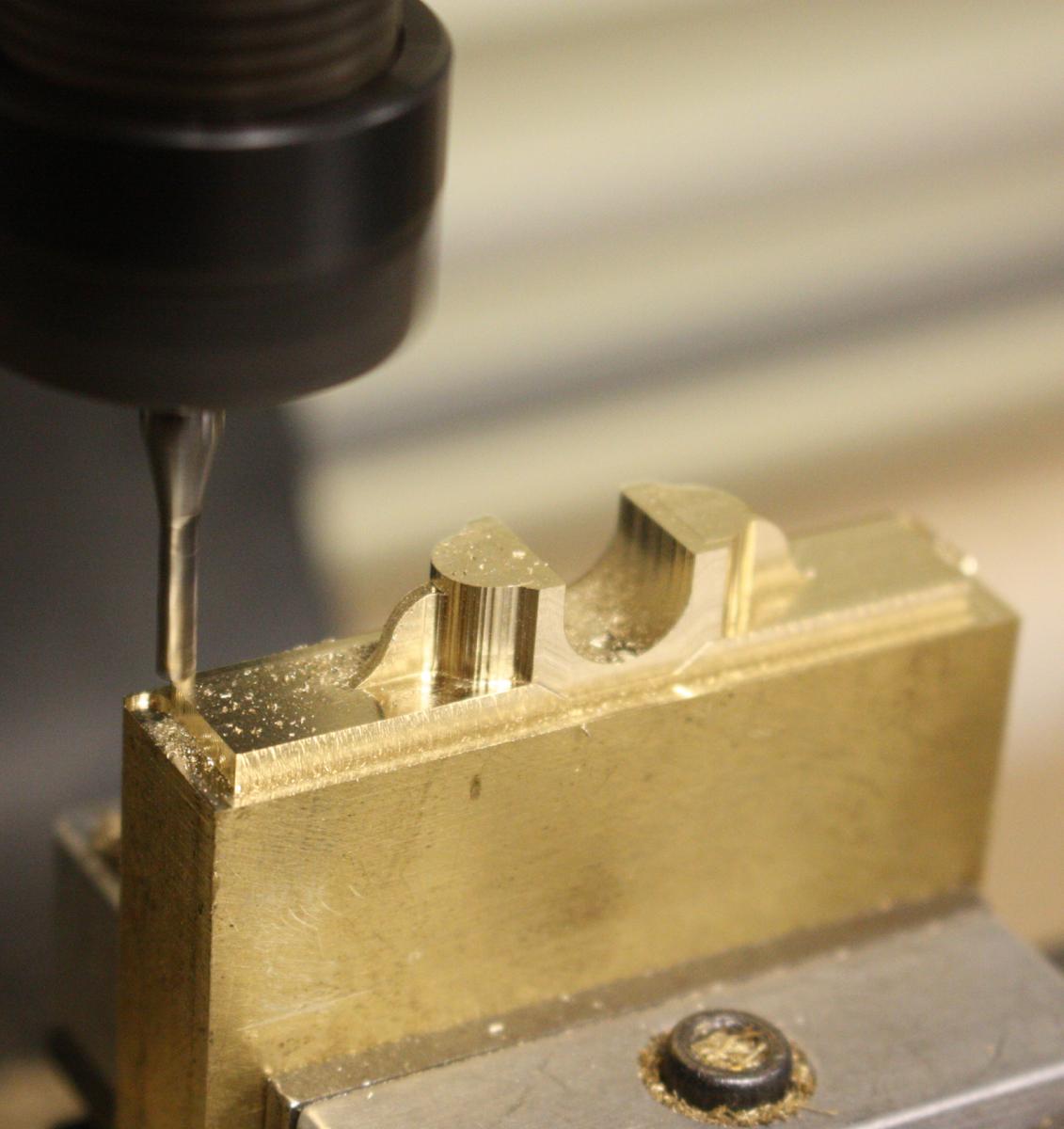
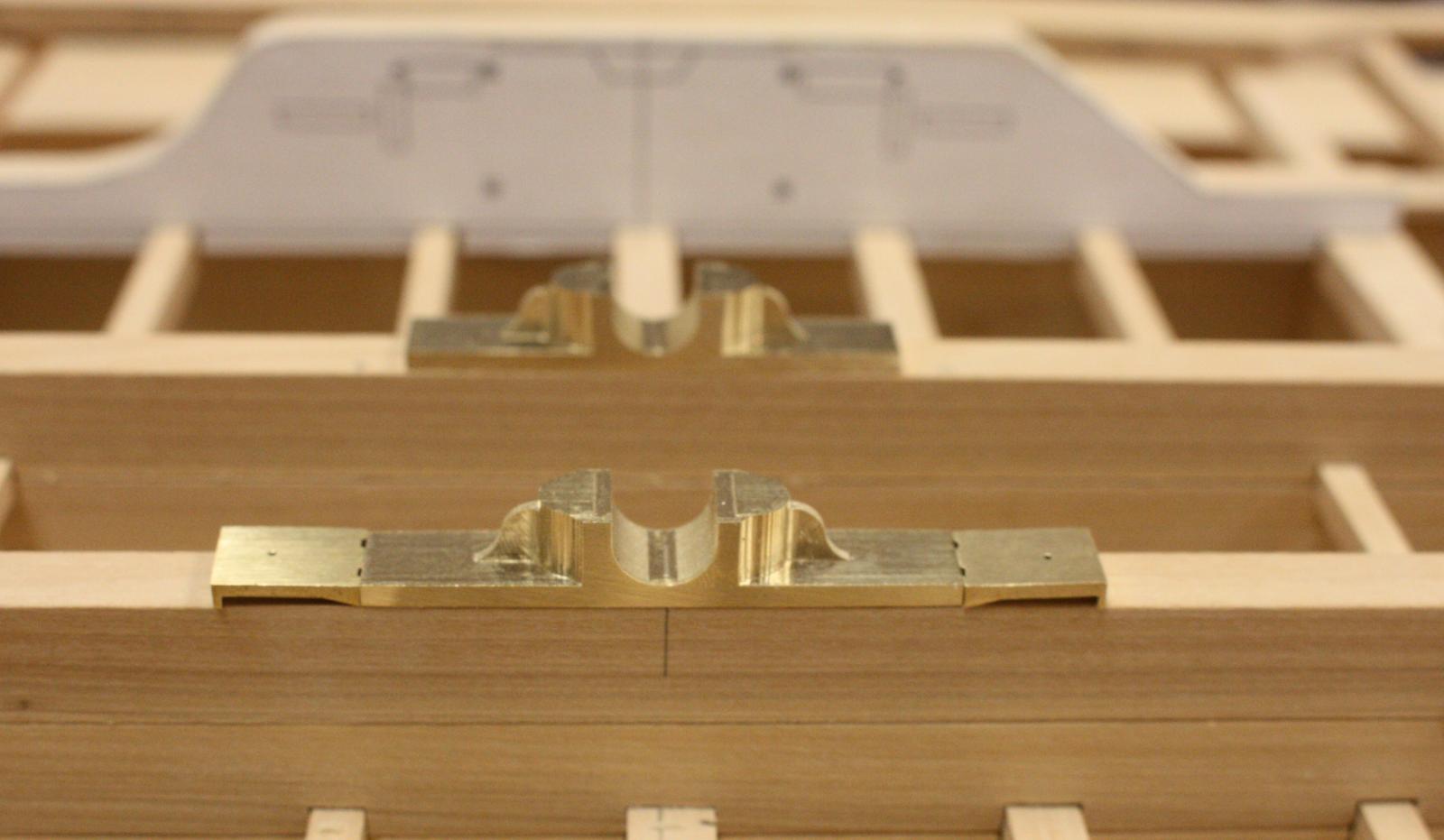
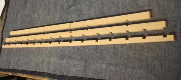
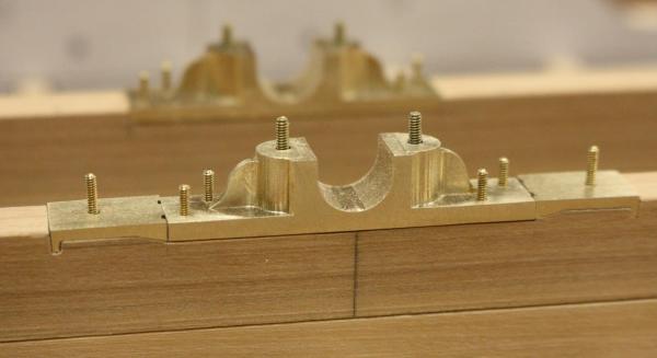
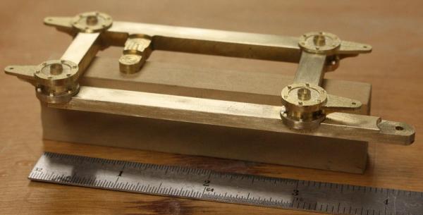
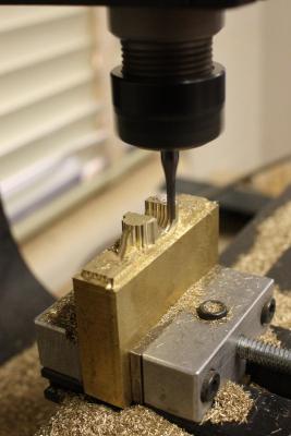
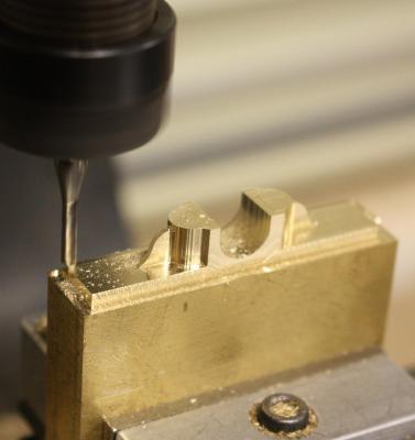
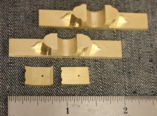
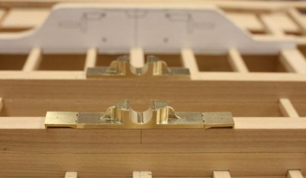
Not a lot of visible progress this week. I spent most of my time finishing the hull planking on the second model. I was able to start milling the sixteen bearings that will be needed for the flywheel and paddlewheel shafts. Roughing cuts on the main flywheel bearing Last few passes of the finishing cuts. Used a 10% stepover, probably should have used 5% Bearings and buttress plates before drilling the bolt holes. Bearings before being notched into cylinder timbers. The buttress plates were mounted forward and aft of both the main flywheel bearing and the engine sole plate. The sole plate, bearings and buttresses were all notched into and bolted directly to the cylinder timber and wedges were driven into the notches in the buttresses. An interesting feature of this wreck was that the buttresses were only fitted on the bearing and sole plate on the starboard side of the vessel. Kevin an I were curious to know if this was typical for steam engines. If anyone has an idea about this arrangement, we would love to hear it.
- 701 replies
-
- 26
-
-
Thanks Kurt, I had a great time at the conference and am really enjoying being back in touch again. This site is a wonderful asset to have. In the past I never had much opportunity to get on-line but I got a new iPad and it makes it so much easier to keep up with everything. I'm really looking forward to getting to know everyone. Glenn
-
Hello Keith, Thank you for your kind words. I am using a TAIG cnc mill from TAIG tools. http://www.taigtools.com/cmill.html I have two of the mills, one for home and one for the office, and it seems like they are always running. You'll find no end of uses for them. I use AutoCAD to design my parts and an old version of BobCAD to create my mill routines. If I have to create a more organic shape such as a figure, MeshLab works pretty well. The mills comes with everything you need except the design program.
-
Hello Dimitris, I'm happy to have you along. I would love any input or suggestions you might have as well.