HOLIDAY DONATION DRIVE - SUPPORT MSW - DO YOUR PART TO KEEP THIS GREAT FORUM GOING! (Only 20 donations so far - C'mon guys!)
×

ggrieco
-
Posts
276 -
Joined
-
Last visited
Content Type
Profiles
Forums
Gallery
Events
Everything posted by ggrieco
-

ancre La Salamandre by tadheus - 1:24
ggrieco replied to tadheus's topic in - Build logs for subjects built 1751 - 1800
Beautiful! Incredible detail!! Glenn -
I wish my hands were steady enough to bevel runs of planking so fair. Beautiful work! Glenn
- 3,618 replies
-
- 4
-

-
- young america
- clipper
- (and 1 more)
-
Beautiful! Such incredible detail! Glenn
-
Thanks everybody, I can't tell you how much I appreciate your comments, likes and advice. I do feel like cutting the flywheels may not have been the best way to go and I'm reconsidering how to display the flywheels. Now that the lower half of the hull is missing, I have to come up with an idea that won't look awkward. One idea I've considered is to have the model up on a plinth that is textured and painted to look like water on top. The paddle wheels would be cut at water level only on the port side. On the starboard side, the plinth would be cut away to show a complete paddle wheel. Since there will be cutaways of the superstructure on the starboard side to show the machinery, this would be keeping with that theme. Any ideas for not having to cut the paddle wheels would be greatly appreciated! Cathead, yes, it would have saved me some time to cut the rims with the mill but, I was afraid if I didn't have the complete circle it would be hard to guarentee the shape. When reassembling the original wheel, it was amazing how flexible the cast iron actually was. We had to continually measure and retighten the bolts to get a true shape. I was afraid it would be just too flexible with the small brass pieces. Greg, all my lathe turning is freehand. There are times when I wish I had a cnc lathe - like making the carronades for Jefferson - but lathe turning is something I love to do and prefer (most of the time) to do it by hand. Glenn
- 701 replies
-
- 11
-
-
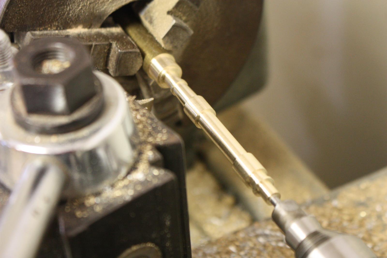
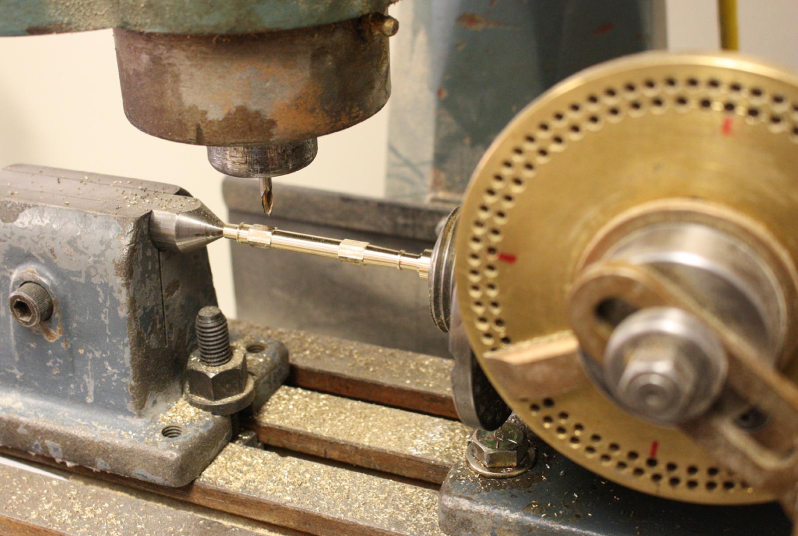
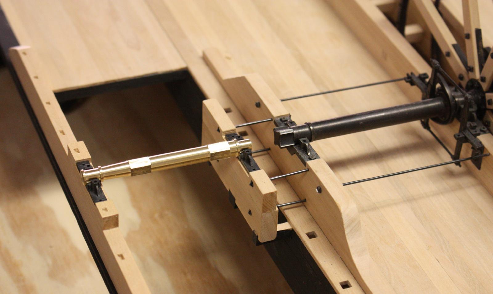
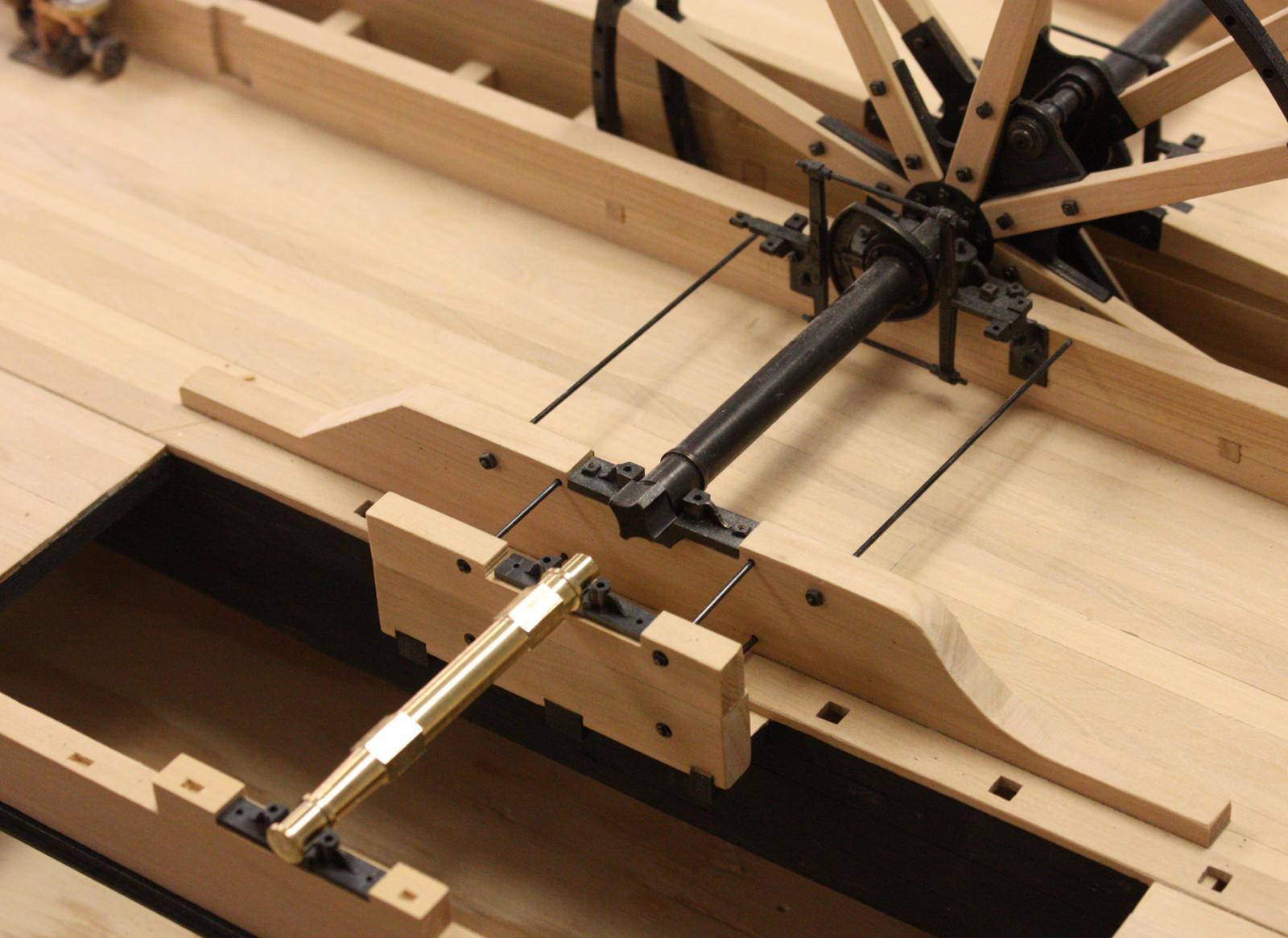
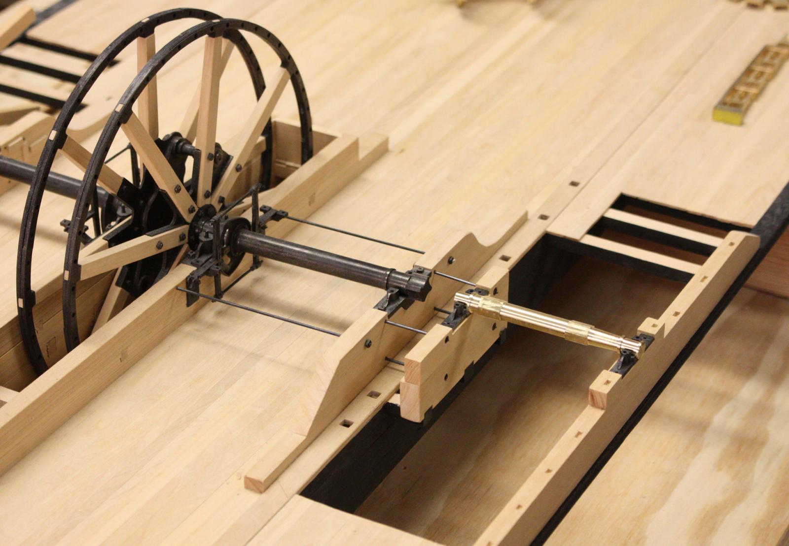
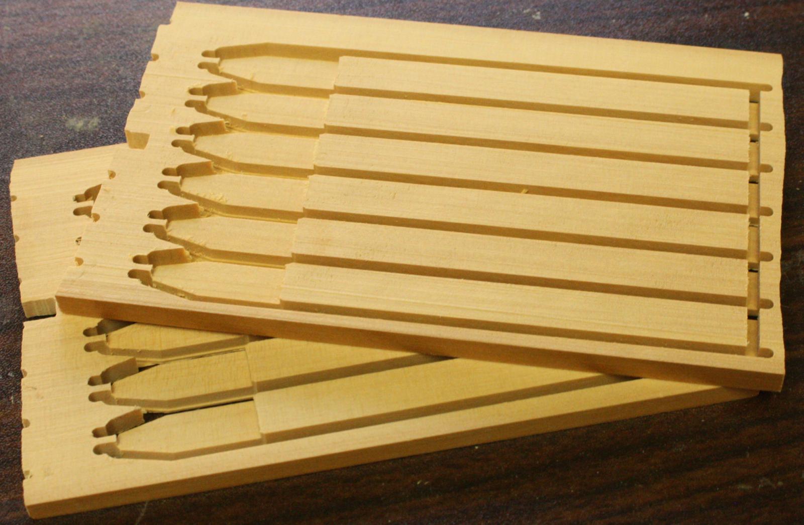
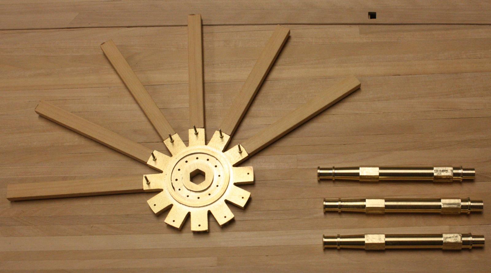
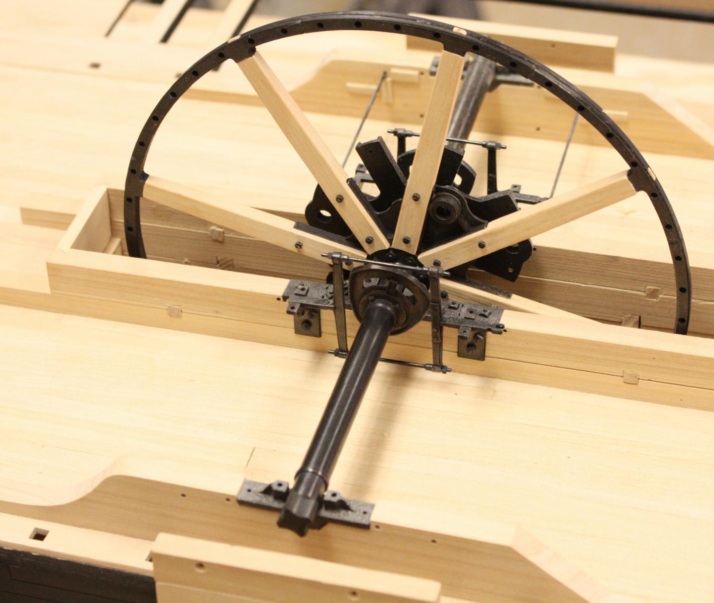
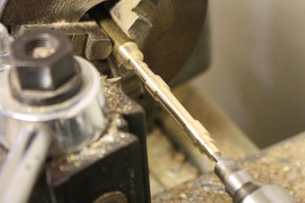
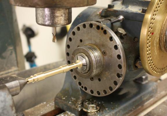
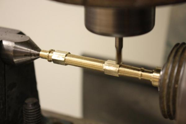
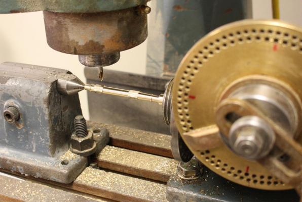
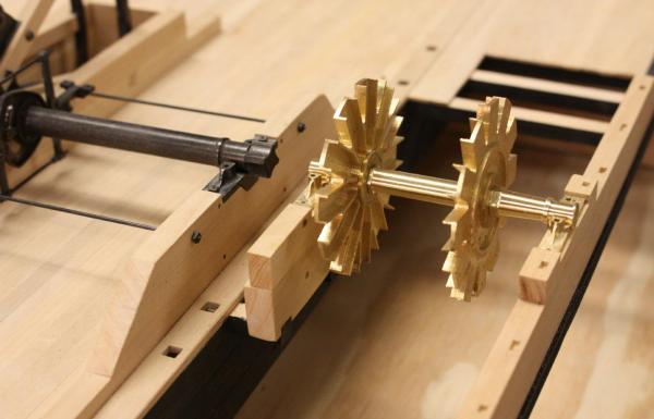
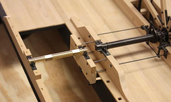
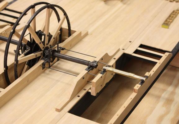
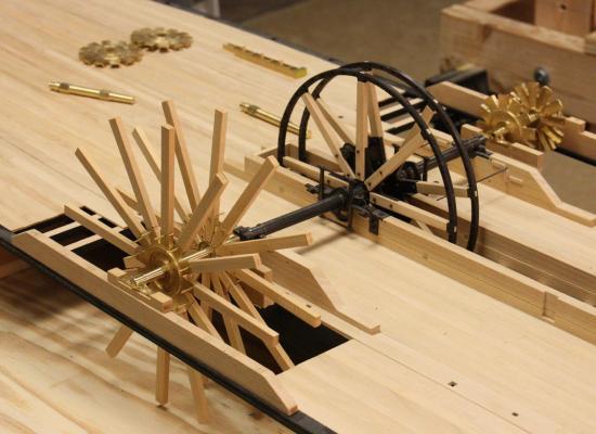
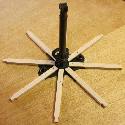
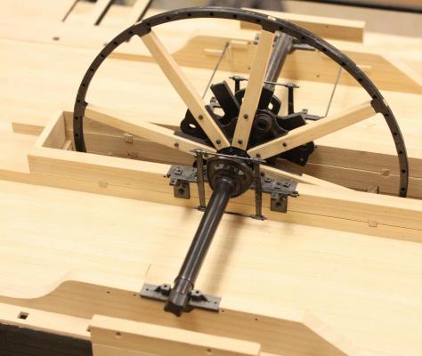
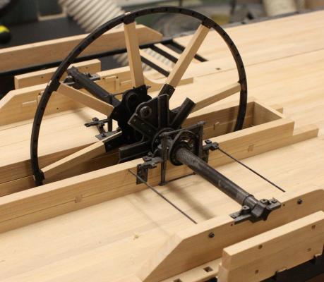
With the deck finally complete on the second model, i was able to convert my mill from a thickness planer back to a mill. I have been putting off turning the paddlewheel shafts because they have hexagonal bosses that require a dividing head on the mill. This week I was able to make some progress on the paddlewheels. Turning the paddlewheel shafts. Milling the hexagonal bosses. Test fitting the paddlewheel flanges. On Heroine, all of the flanges were damaged to some extent. A few had several of the arms broken off and were reinforced by flat iron strap. Next week I will reproduce this damage and repairs. Bearing timbers in place with iron tie rods. Paddlewheel spokes fresh from the mill. The mill cuts the mating pieces so accurately, there is almost no fitting required. Just a little clean-up and they slid tightly into the channels in the flanges. Test fit of the starboard paddlewheels.


- 701 replies
-
- 36
-
-
Thanks everybody! Greg, I think I could have used a shot of whisky first but i breathed a real sigh of relief when it was over and the two mated correctly. I was so afraid of laying them out improperly. I hated to cut them but it made future construction a little easier. Glenn
-
Hello Steven, I spoke to Cemal yesterday, he says hello. We talked for a while about the keel and he had some more recent ideas about it.. On each end of the keel on these vessels there is first a timber that slowly curves upward like a forefoot, followed by the stem or sternpost. On another galley that was excavated at Yenikapi, the builder was able to fabricate the entire keel and stern curved piece from one timber. We had a tracing of the timber and originally I thought it was a flat keel that rose in the stern. Cemal has pointed out that it was just a combination of these two timbers. If you have a copy of the IJNA article that shows the site plan for YK4 you can see YK4s sternpost and a piece of this curved timber just above the stern end of the remains. Sorry for confusing the issue and I hope my explanation isn't just more confusing. I wish I had the tracing with me to post but they are in a box in my office. I'll look for it next week and if I can find it I'll post it. Glenn
-
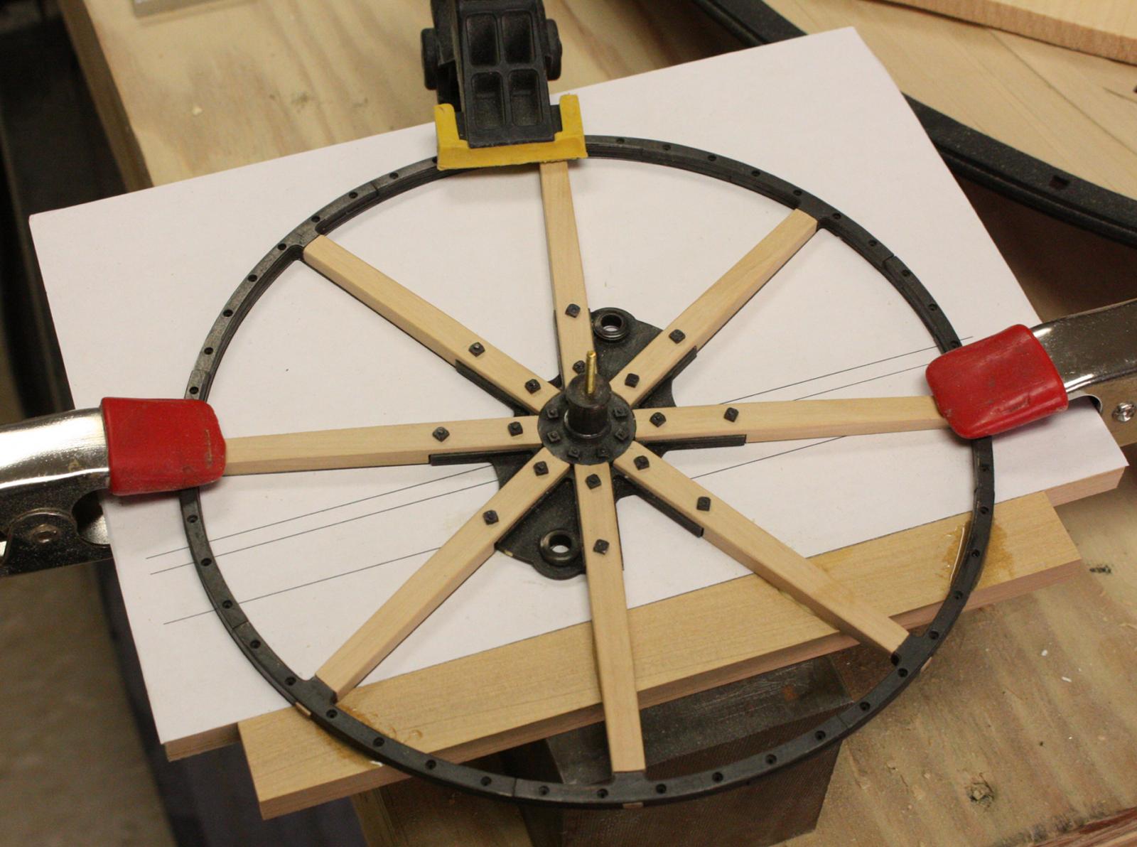
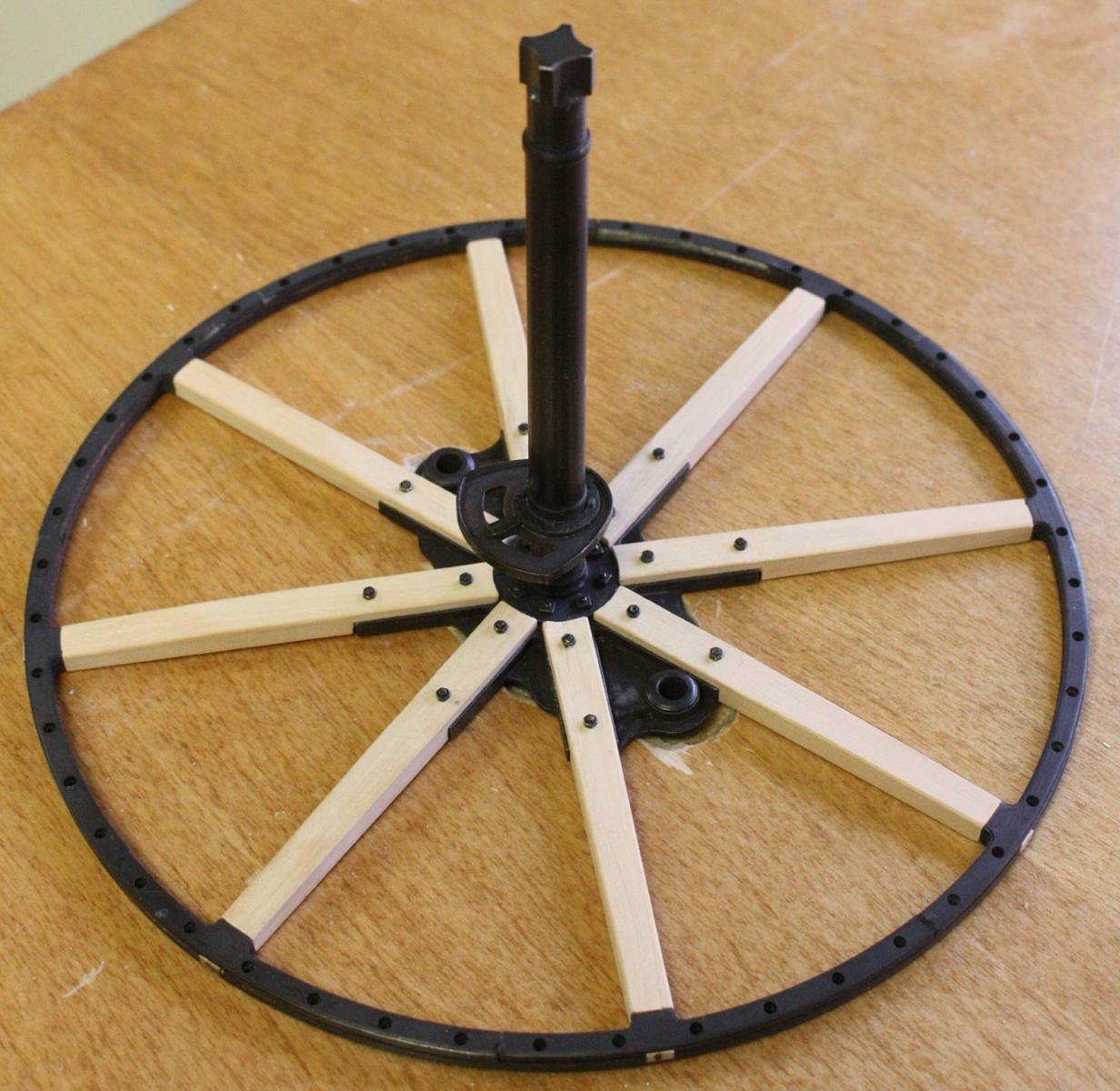
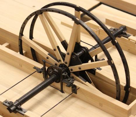
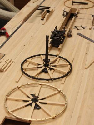
I've spent most of the week finishing the deck planking on the second m0del and trying to catch up on it's machinery. I was able to assemble the flywheel pair for the first. Unfortunately, I had to cut off the bottom of the flywheels to fit in the waterline model. Fixture to hold wheel in place while the lower support is glued in place. Wheel glued to support. I used wood glue on the spokes and epoxy on the rim. Lining up the two wheels. Completed wheels in place.

- 701 replies
-
- 28
-
-
Thanks Steven, No problem. I'll let you know if he has any good info on the keel. Glenn
-
Hello Steven, I built the YK4 model for Cemal a few years ago. The wrecks from Yenikapi were divided up between several institutions. Before publishing, everyone was protective of the data they had and we only had access to the forward end of the keel on YK4. Fortunately, Cemal had some knowledge of the other keels which we discussed while brainstorming what YK4's stern looked like. It has been a while since I looked at the research but if I speak to Cemal tomorrow, I'll ask if there are any published drawings of the other keels. I'll also pass along your thanks to him. Glenn
-
Hello Steven, There are fragments of keel from three of the Yenikapi hulls. Combining the evidence, it appears that they were flat for about the first 2/3rds (except for the stem) of the vessel and then swept up at the stern. Perhaps to improve the turning ability? Glenn
-
Michael, When I saw the small clamps you made I wanted to ask for the plans. I'm happy to see you posted them -- they will come in handy! I'm loving this build by the way!
-
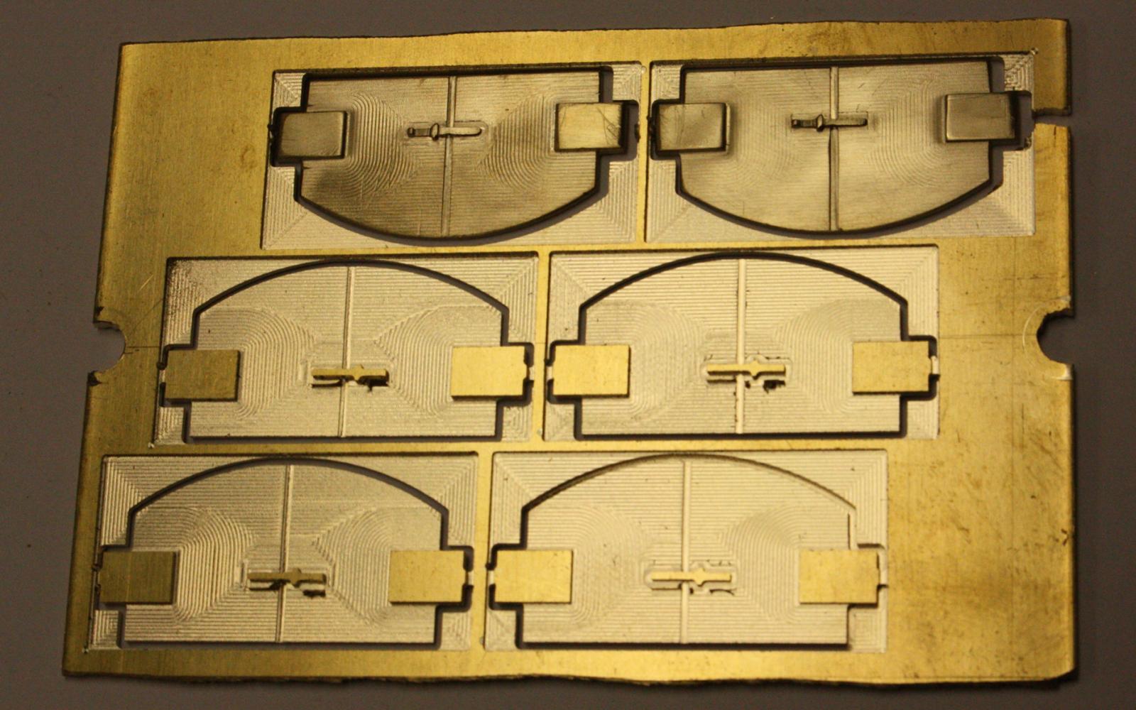
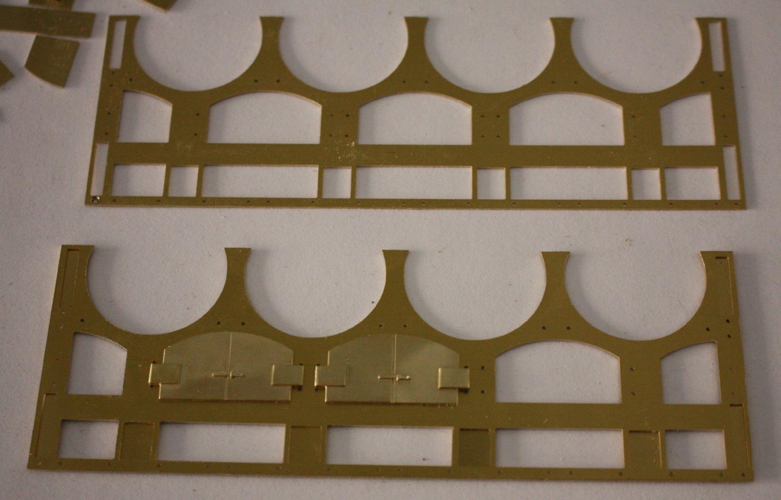
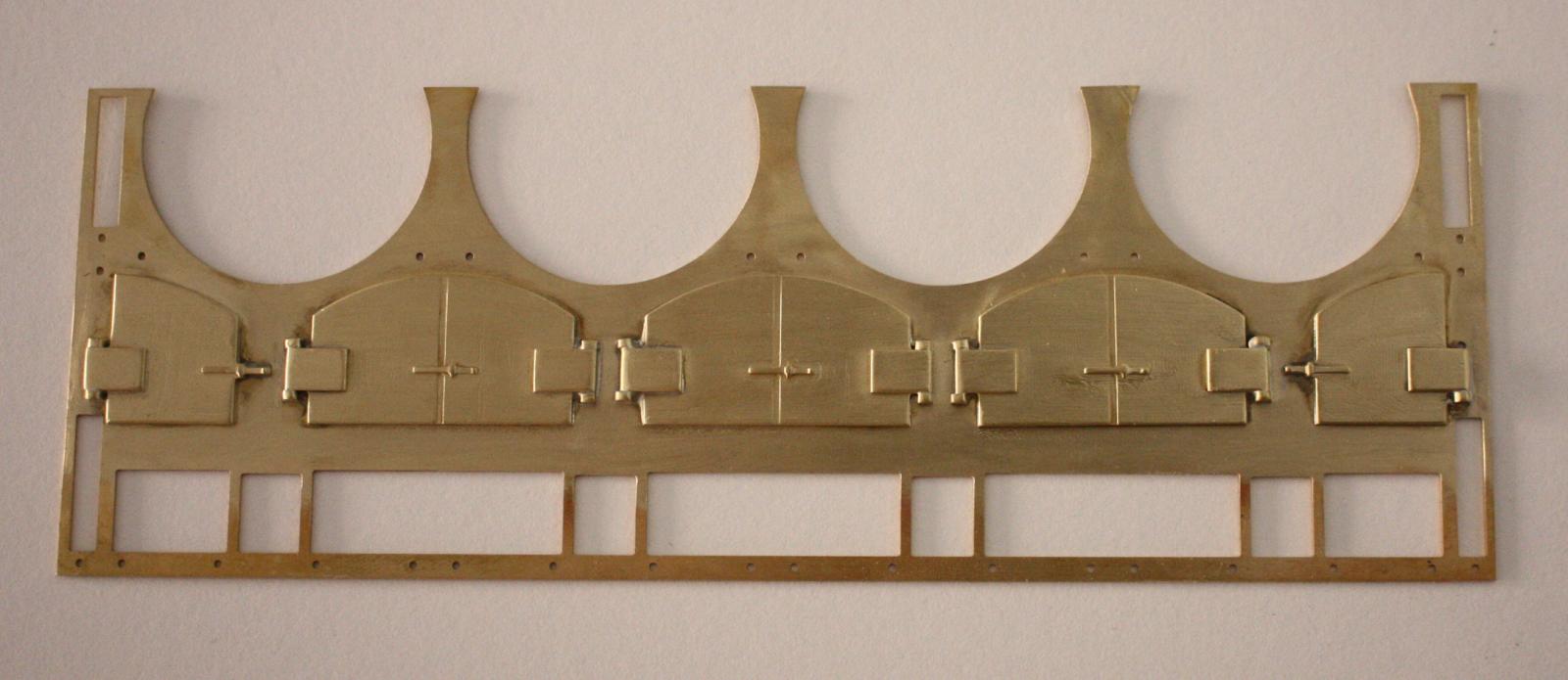
Thanks druxey, albert, Cathead and Michael, Yes Michael, I am simplifying the doors a little. In the beginning, I had high hopes to make hinged doors with a working latch and one door was going to be open showing the fire grates inside the firebox. I wish I had more to go on but on these early boilers the doors would have been fairly simple. Either plate with a riveted hinge or cast with integral hinge. I went with a representation of the second. On later boilers you see more substantial doors with draft holes and internal baffles but they too late for Heroine. Other than these considerations, It is pretty much as you said, a representative element. I'm hoping that once they are blackened and partially obscured by the boiler breechings and other structures, the lack of details will be forgiven and they will provide a believable appearance.
-
Thanks John, Ken, George and druxey, Yes druxey, I'm more confident now that we have four boilers. I've seen so many references to Western river steamboats having two or three boilers but then we found sources pointing to early riverboats having four or five boilers. We've recently discovered that on the earlier vessels, single flue boilers were common but not very efficient. By the end of the 1830s, two flue boilers were becoming the norm. The increased efficiency allowed fewer boilers. I think most references to boilers are from the 1840s and later and don't consider the single flue boilers. Adam Kane's thesis on steamboat machinery includes an interesting table in the appendix that gives the engine and boiler specifications for several early steamers. It is interesting because instead of referring to number of boilers, it refers to number of flues. Although there is some difference in the size of the flues, four boilers with one flue each produces about the same volume of steam as two boilers with two flues each. Kevin has put together a list of several early riverboats that he has researched in government documents and it appears that most of the early boats had four boilers or more. Finally, the most convincing piece of evidence is the contract for the Yellowstone. A single centerline engine identical in size to Heroine's, similar sized flywheel and stroke and from the same period. The contract calls for four boilers 36 inches in diameter and 16 feet long. We know heroine's boilers were 34 inches in diameter and the sixteen foot length fits perfectly between two sets of doubled deck beams. I was really at a loss before but I feel pretty sure that we have it right now. Glenn
-
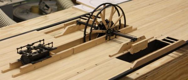
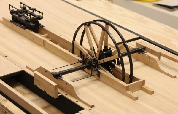
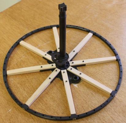
Hello everybody, I usually post my progress on Saturday morning but tomorrow we have a big family get-together for my mother's birthday tomorrow which will probably keep me away from the computer for most of the day so I decided post these photos today instead. The flywheels are going together. Unfortunately I wasn't able to complete the port wheel before the weekend. I've also made a little more progress with the boiler front. Firebox doors. Except for two pieces of the firebox opening that suggest an arched door, we have little to go on for the design of the doors so I have kept them fairly simple. Too many pieces to solder at once. I decided to leave the panel inserts off until after blackening and will epoxy them from behind. Test fit of the starboard flywheel spokes. Completed starboard flywheel. Starting on the port flywheel. Starboard view of starboard flywheel. View from port side.


- 701 replies
-
- 31
-
-
Wow! I could explore these drawings for hours. They are incredible! Thanks. Glenn
-
Unfortunately we have very few examples to go on. We know Heroine's flywheels were at least symmetrical with the only possibility of being out of balance might have been from inconsistent casting of the individual segments. I think they were intended to be fairly balanced. It doesn't appear that the flywheel was used for long on western river boats and there is only the mention of them with no design descriptions. I have a feeling there is much to learn from stationary engines of the early 19th century but I haven't had a chance to do the research.
-
A beautiful work of art Druxey! I tried clinker planking once -- a polish Pomeranka. I think I made it to the fourth strake before it all went into the trash. I am really enjoying this build! Glenn
- 641 replies
-
- 4
-
-
- greenwich hospital
- barge
- (and 1 more)
-
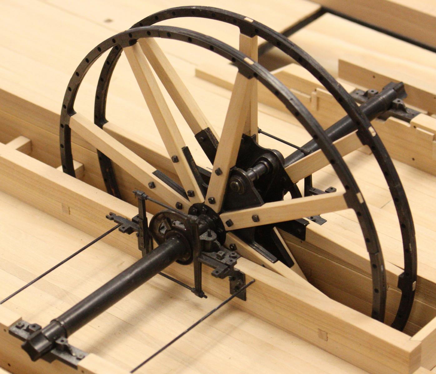
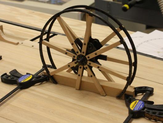
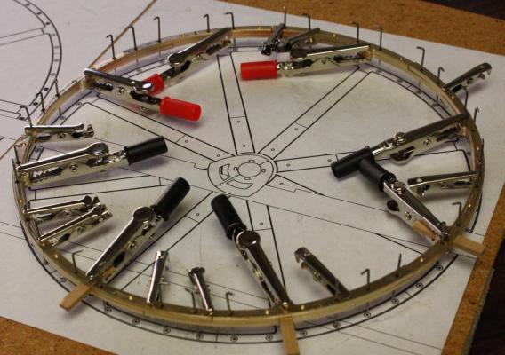
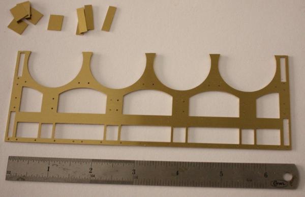
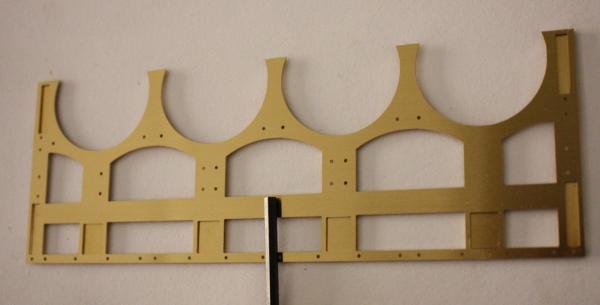
Thanks everybody, I really appreciate your comments and likes. Druxey, when we reassembled the original, we didn't have much trouble with distortion but we did realize the the Huge differences in thicknesses between the rim segments. Some of the segments definitely stood proud of adjacent segments. I wonder if there was a lot of difference in the shrinkage of different casts. Cathead, that is a good question! Heroine had 12 spokes per flange but I recall seeing paddle wheels with more. I would love to know the motivation as well. I've seen some smaller flywheels on stationary engines with six or five. I'm sure. In those situations it was just dependent on size. If you find any good reasoning, I'd love to hear it. Mark, yes, they are bolt holes and your idea would work well. The through holes are only 1/32 of an inch (the original bolts were 3/4inch). I looked into purchasing a smaller size from microfasteners.com but after seeing the price for 400 of them I decided to try to rivet the holes instead. I actually made one attempt to rivet inside the pockets and gave up opting for lots of alligator clamps instead. I think this is a good time to point out they unusual but ingenious way the rims were actually bolted together. There were actually two different castings for the rims. They were exactly the same but the inner rims had square pockets and the outer had round pockets. The bolts had long hexagonal heads that went in from the outside round pockets and were fastened on the inside with square nuts that fit fairly snugly into the square pockets. It is interesting because the tool used to tighten the bolts was an early socket wrench. I hope this description makes sense. Glenn
-
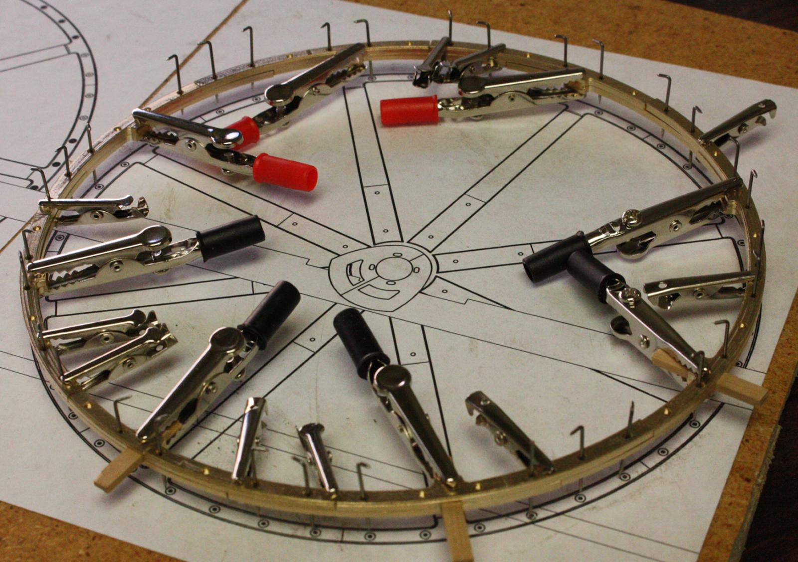
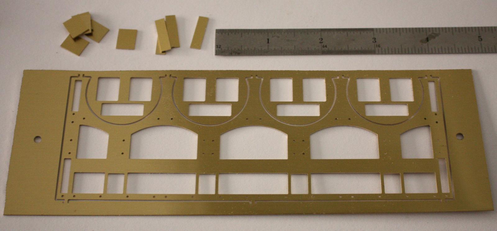
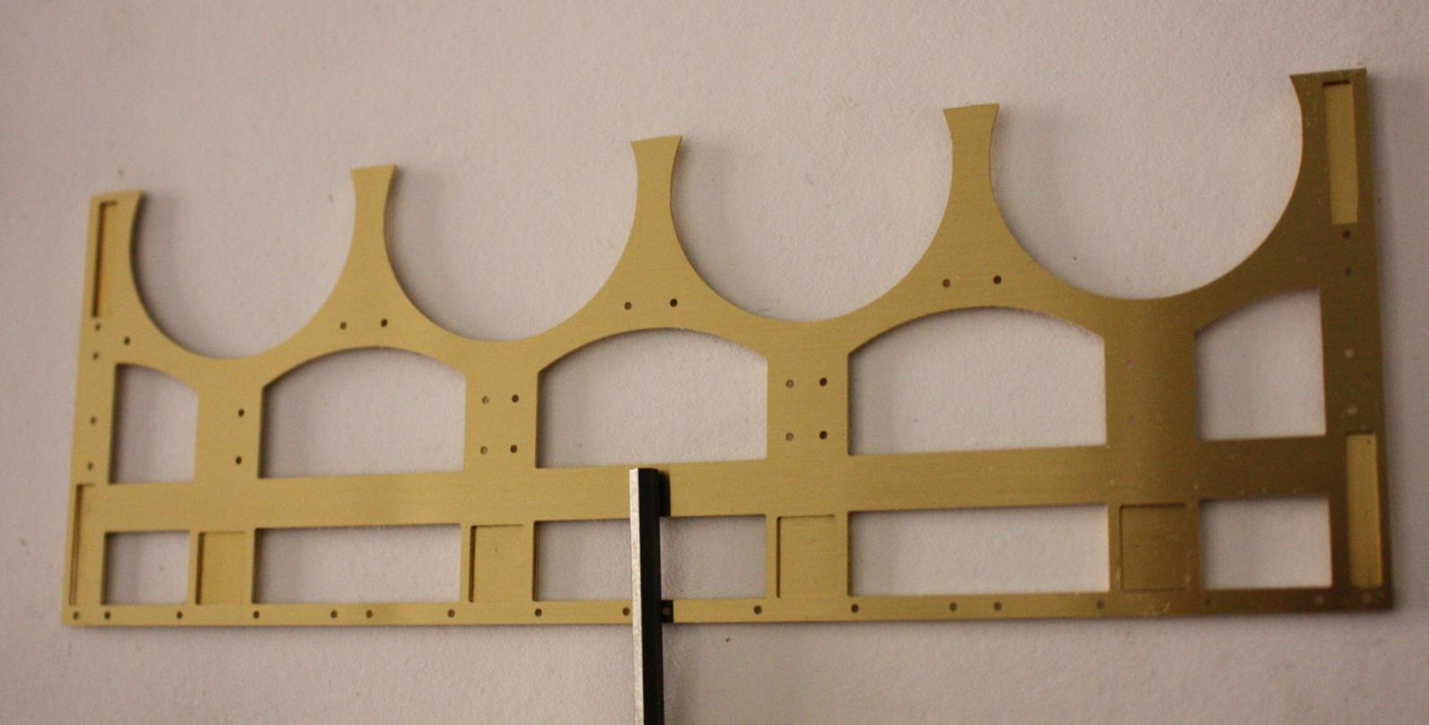
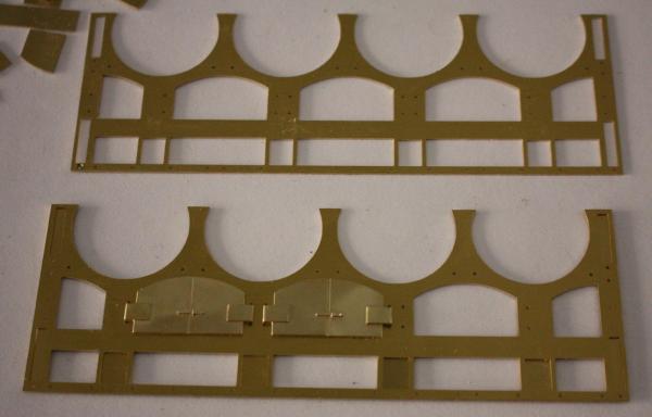
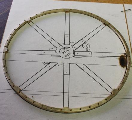
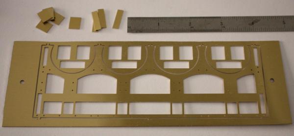
Continuing with the flywheels.. probably one of the most frustrating soldering jobs I've had to do. All sixteen pieces of the flywheel rim had to be positioned to ensure the final shape. To add to the problem, since the segments were only machined on one face, the internal stresses in the brass cause each piece to bend slightly out of flat. I had to use lots of alligator clips to hold everything together but there was still some movement when it was heated. Wheel 1 of 4. I've been looking forward to building the boilers. The machining is going to take a while so I decided to jump ahead and let the mill get started while i struggle with the remaining three flywheels. Rectangular pieces are backing for the recessed panels in the legs and sides of the boiler front. Backing pieces in place.
- 701 replies
-
- 29
-
-
I've been thinking ahead to the glazing on Heroine. I think I'll give Micro-glaze a try. Thanks for the info!
-
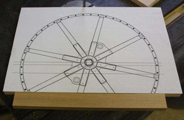
Hello Greg, It has been a while since I did the AutoCAD drawings of the flywheel and I don't remember exactly but, it probably took about a week to take the measurements and reconstruct the flywheel flange,shaft,spokes and rim assembly. Once I have the 3D part drawing I can usually draw the tool path for the part in less than an hour. I used a 1/16 inch end mill to machine the rim segments. These small bits break easily so I had to take my time with the cut. I machined the rims three at a time which took exactly 58 minutes per three with about 1 minute to jog and re-zero the mill between batches. I got a good deal on 3/32 inch end mills some time ago and I try to use them with most of my milling. i can run them considerably faster. The cam frame halves took about 5 minutes each to mill. The spokes were milled 2 at a time in about 5 minutes.
- 701 replies
-
- 12
-
-
Thanks everybody, Looking around this website and seeing all the incredible craftsmanship and beautiful models has pushed me to strive a little harder. I feel like I have a lot of catching up to do with so many of the skills you have. Every time I see your work I am awed and inspired! Glenn
-
Hello Michael, I've been watching a couple of your builds but I don't know how I missed this one. I love a beautiful piece of machinery! Can't wait to see more!