JeffT
-
Posts
2,556 -
Joined
-
Last visited
Content Type
Profiles
Forums
Gallery
Events
Everything posted by JeffT
-

HMS Victory: Caldercraft or Artesania Latina
JeffT replied to darkening's topic in Wood ship model kits
I'm working on the AL Anatomy version. There are no written instructions (video only) and no full size plans with this version. I did see that the closed hull version does have instructions but no words. I don't know if it has full size plans. You can look at the instructions on the AL website. Caldercraft does have instructions but not much for pictures; they are also available for download on the jotika website; but there are plenty of build logs to look at. As someone else mentioned, the CC is huge compared to the AL. -
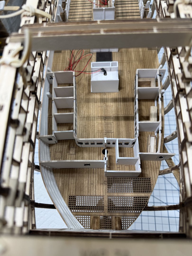
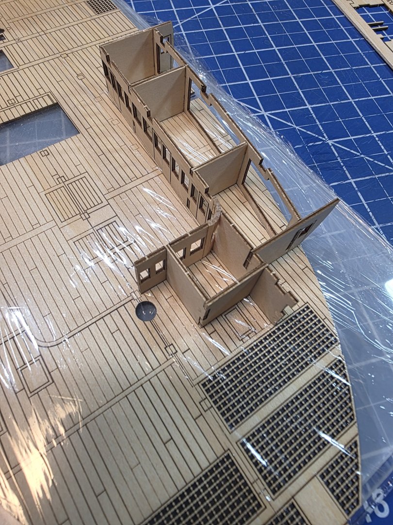
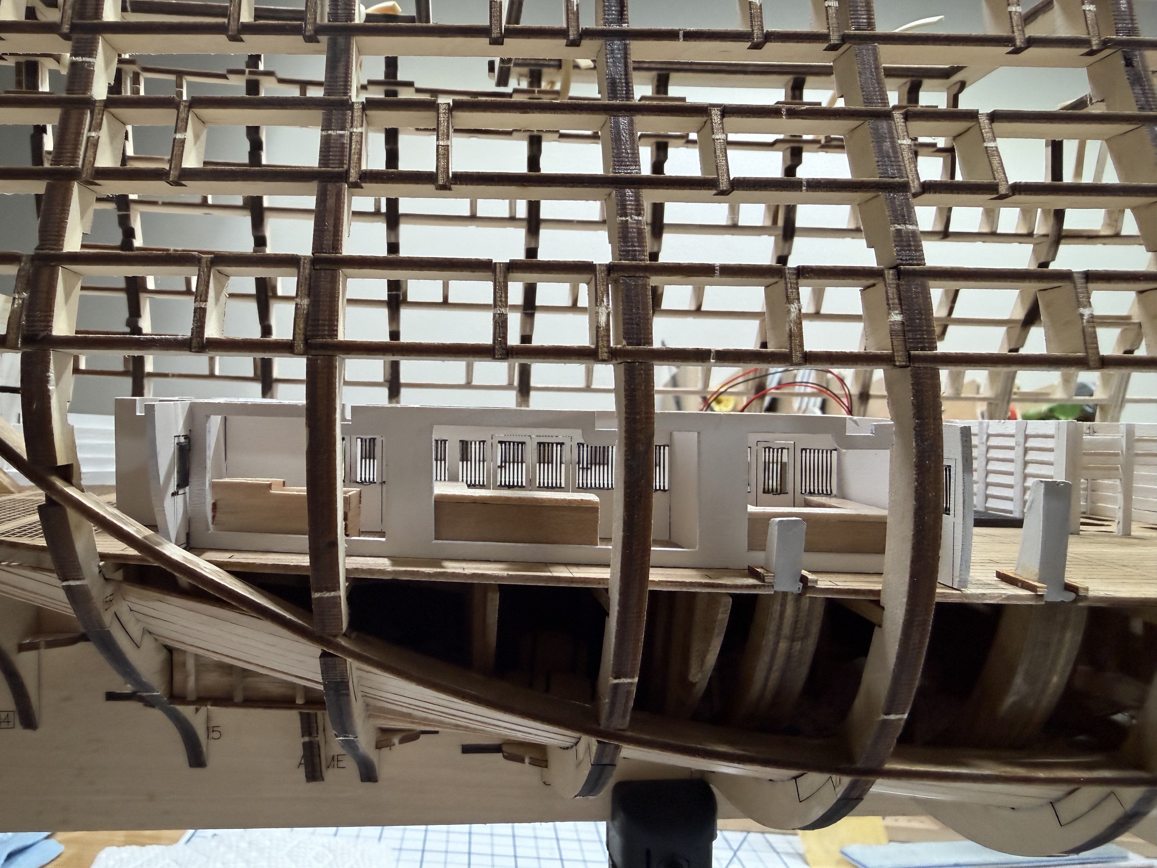
Its been a while but I haven't been totally idle. I finished all the Orlop deck fittings except stanchions and glued in place. I'm glad that I built the cabin sections in separate parts as it would have been too difficult to properly position them in one piece. There are a boat load of stanchions to make for this deck so it will take a while. Most of them require shaping as well. Pictures of the current situation:


-
Fairing lines on the bulkheads are one of the best things
-
It does the first coat but sand down subsequent coats won't raise the grain. I usually do a second and third coat.
-
Water based poly has worked well for me.
-
Ithink the cost may vary depending on vendor. For example, I noticed on ALs online store that they say they cover the US import tariff.
-
I agree. they should definitely flicker. Its about learning a new skill as I've never had a reason to solder anything before.
-
Yes. Light does leak through that area.
-
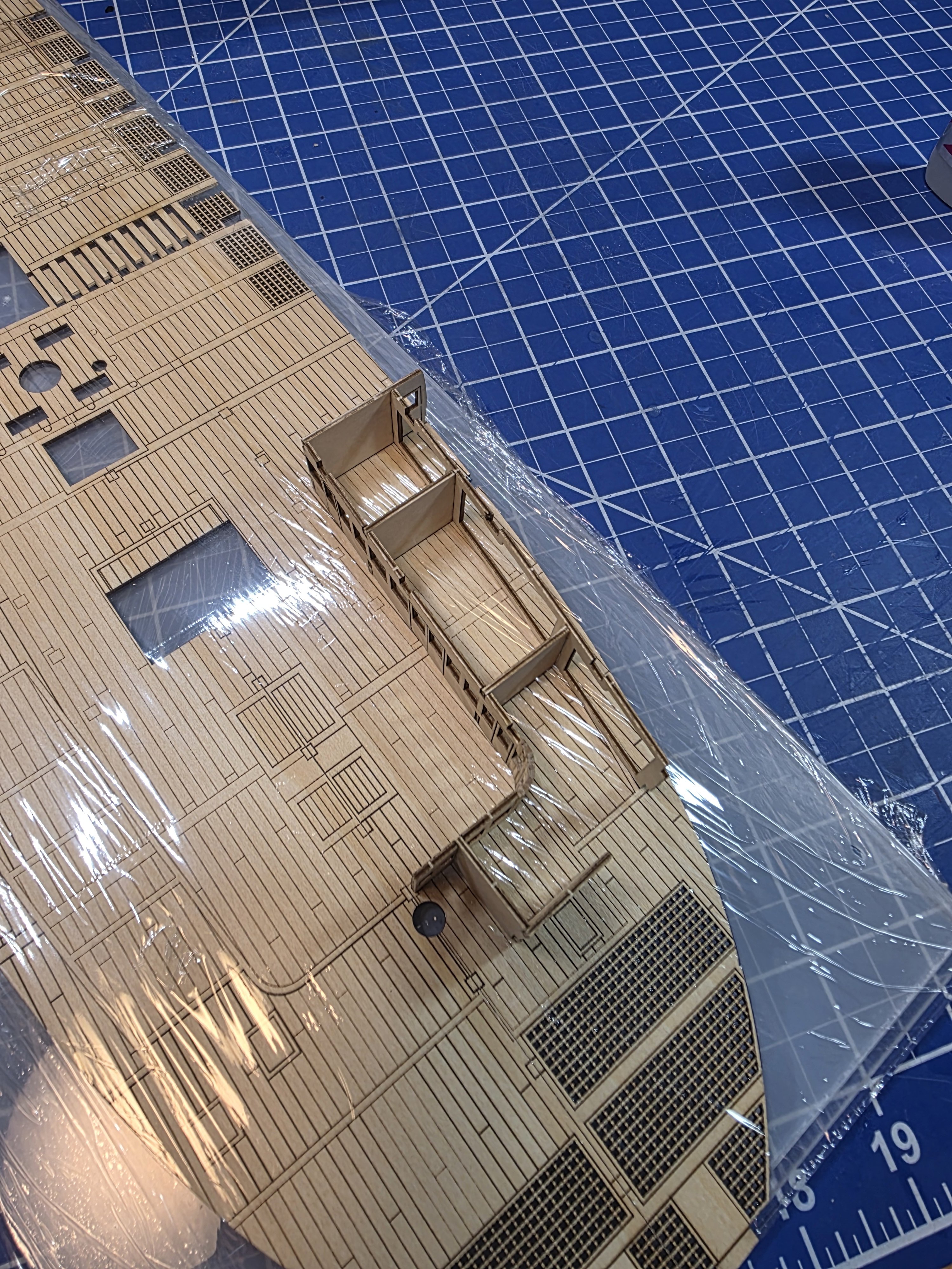
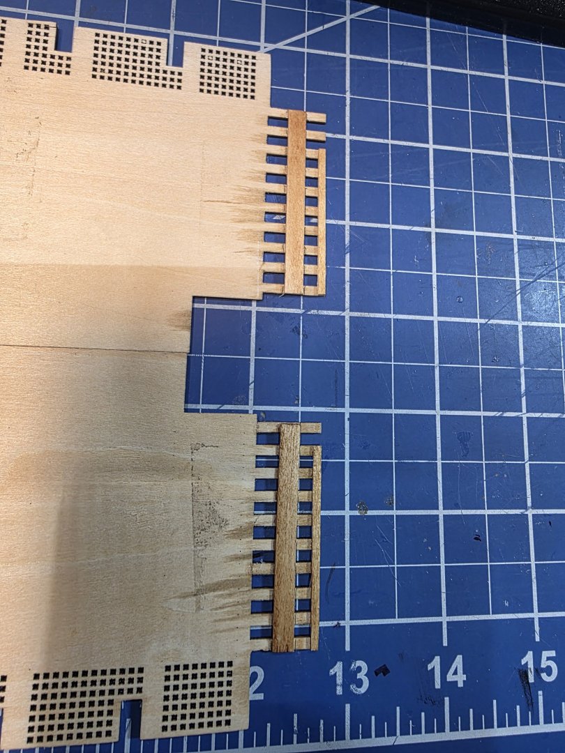
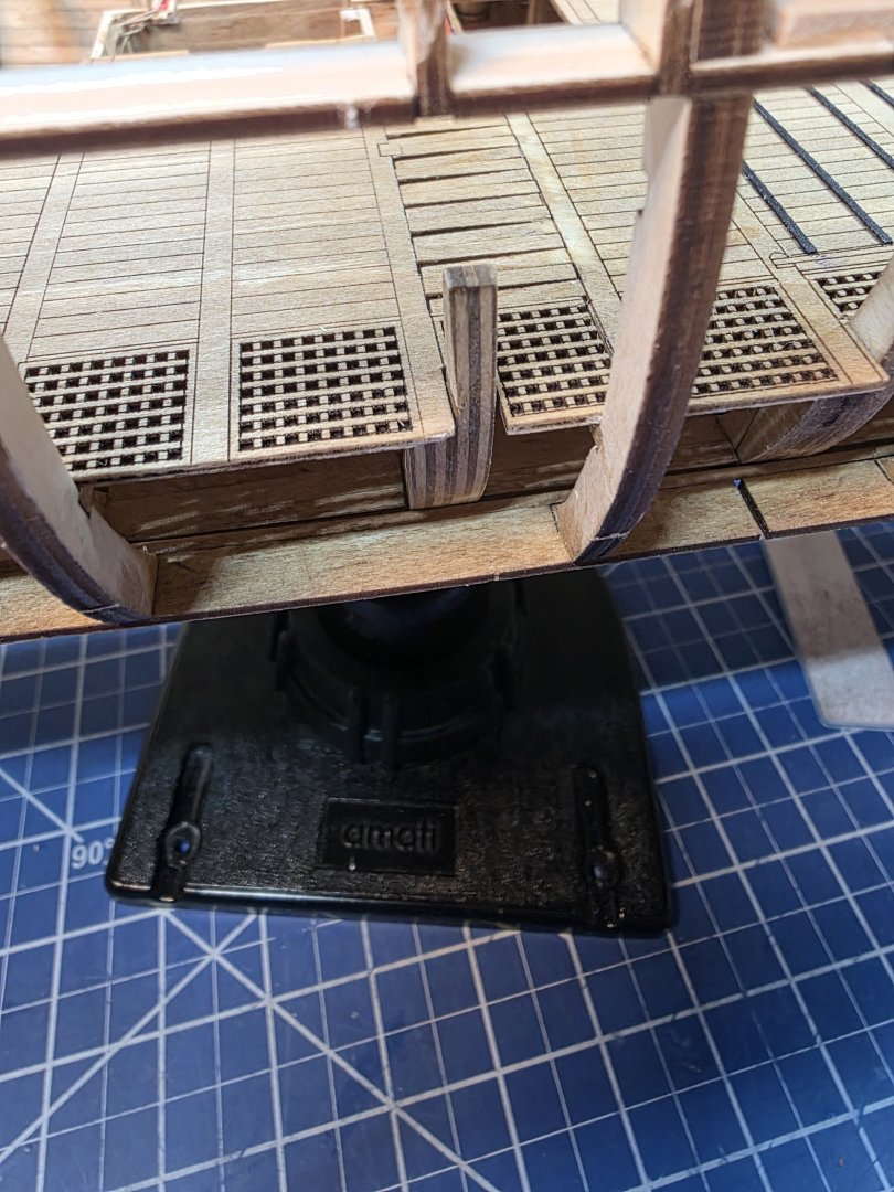
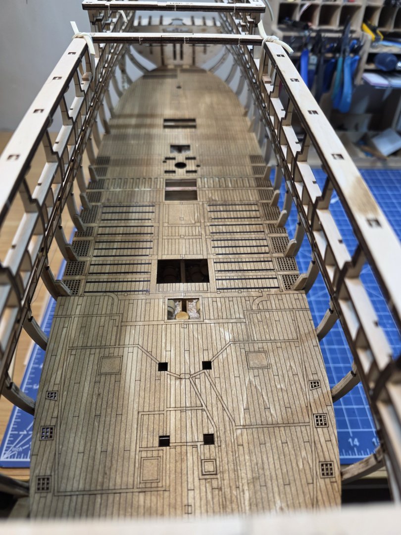
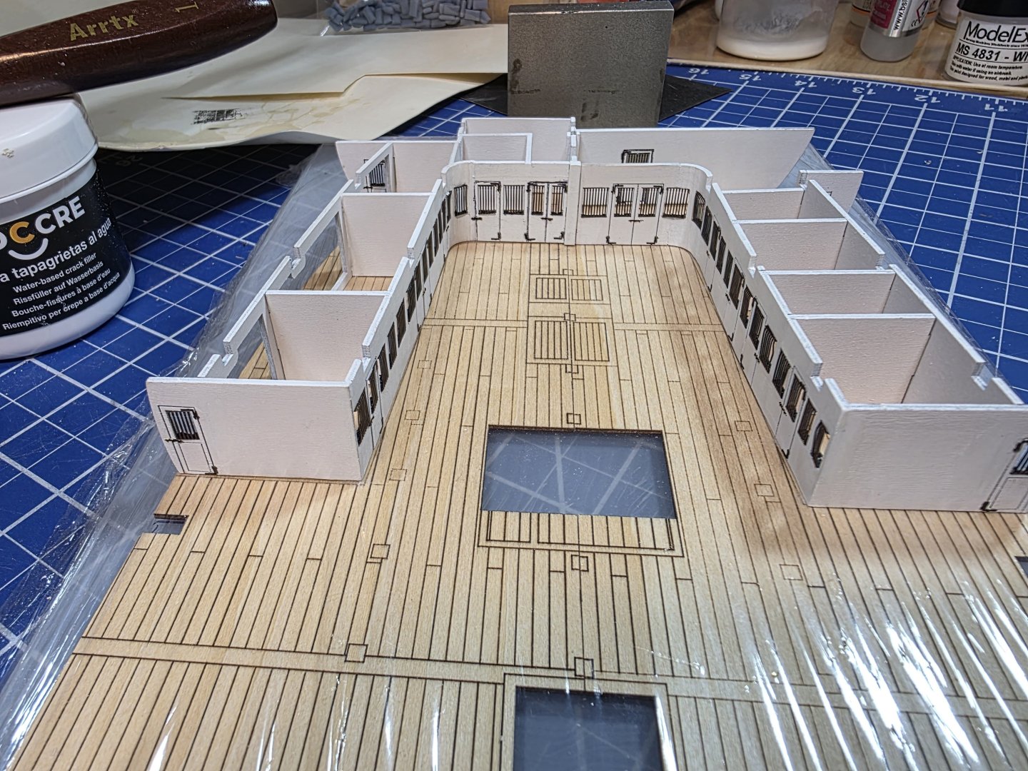
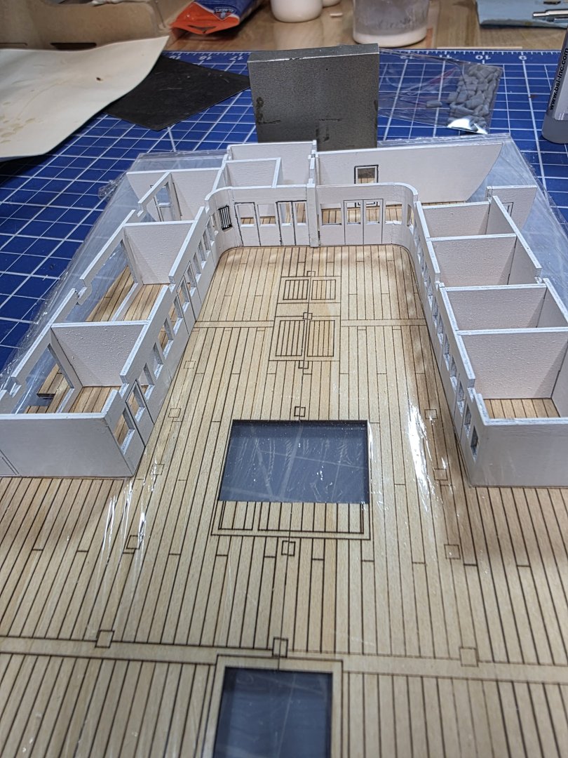
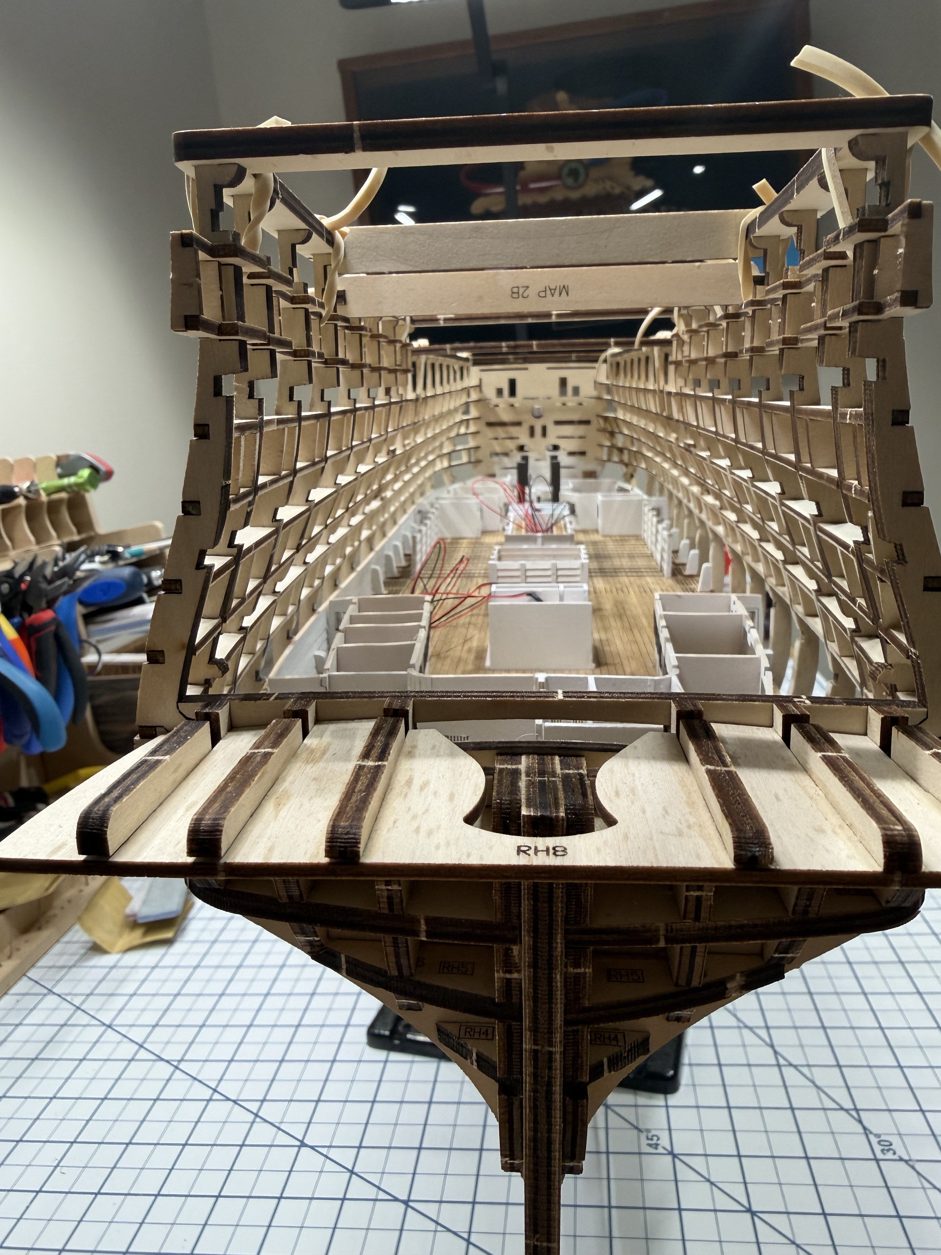
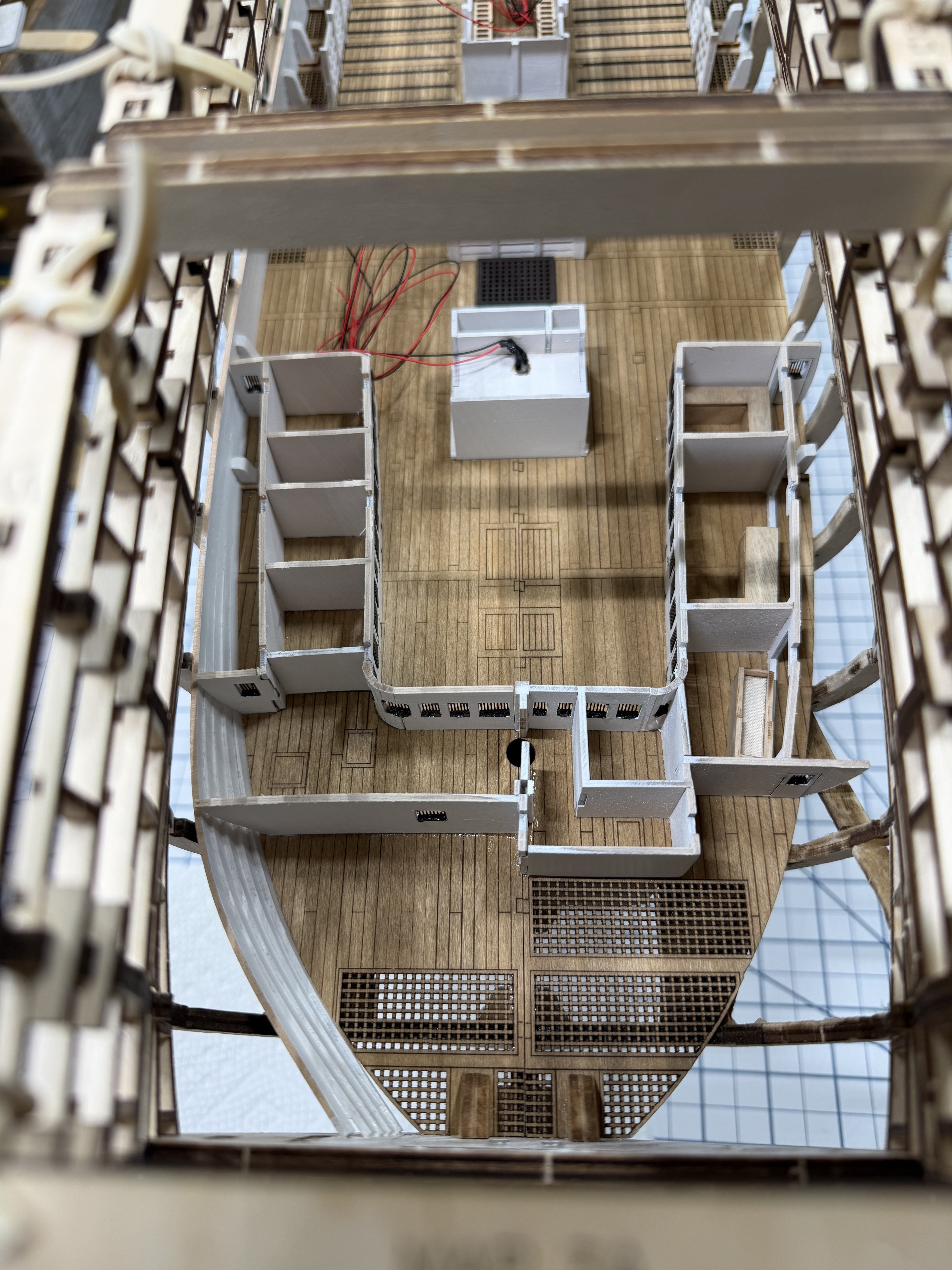
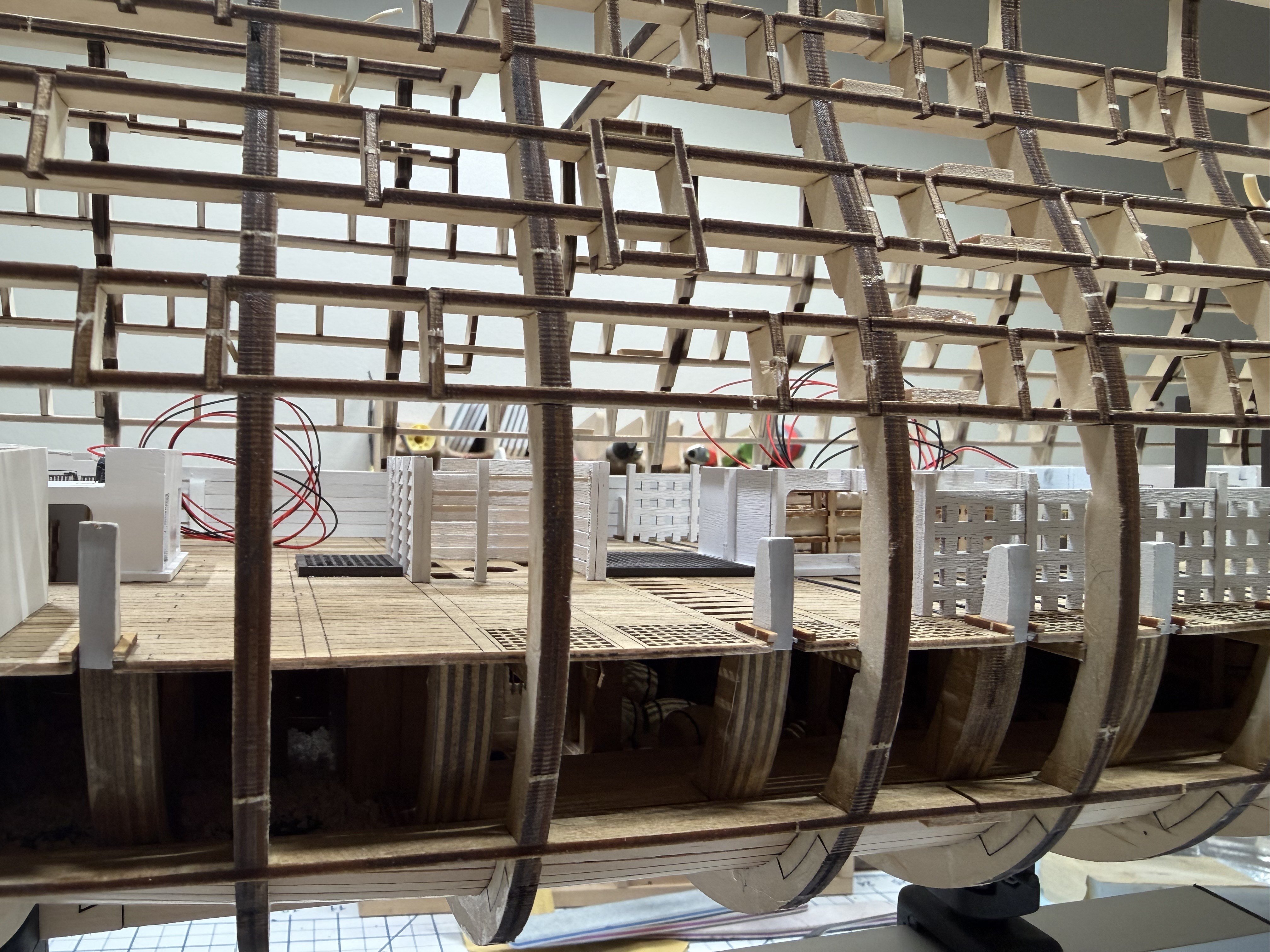
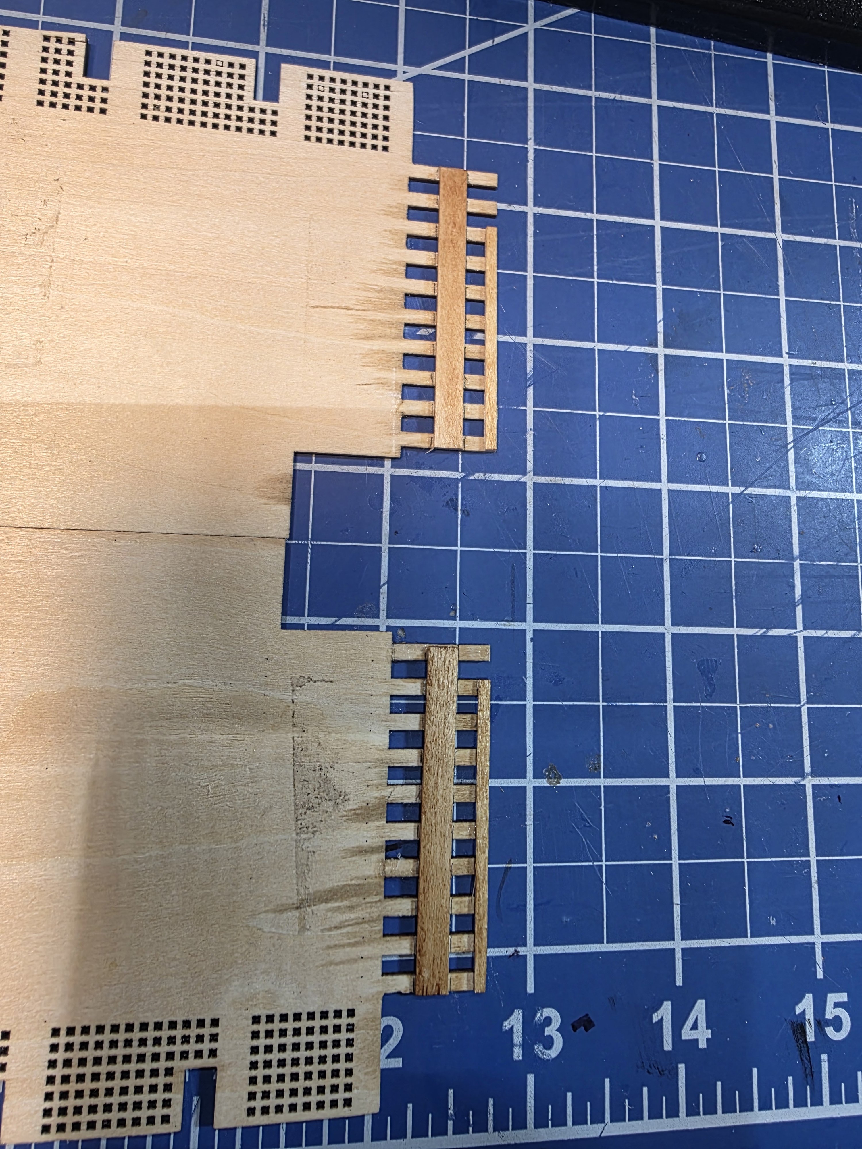
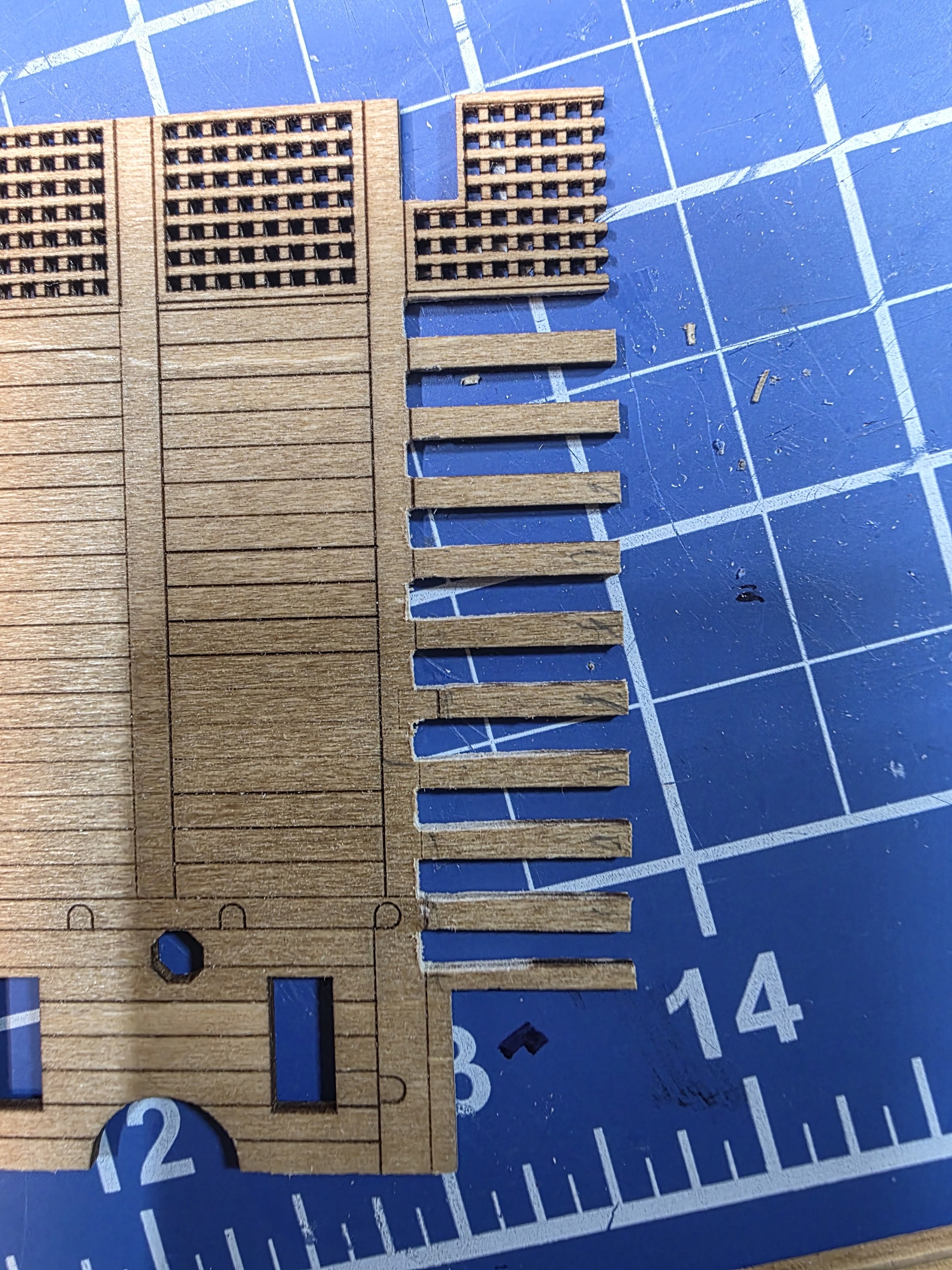
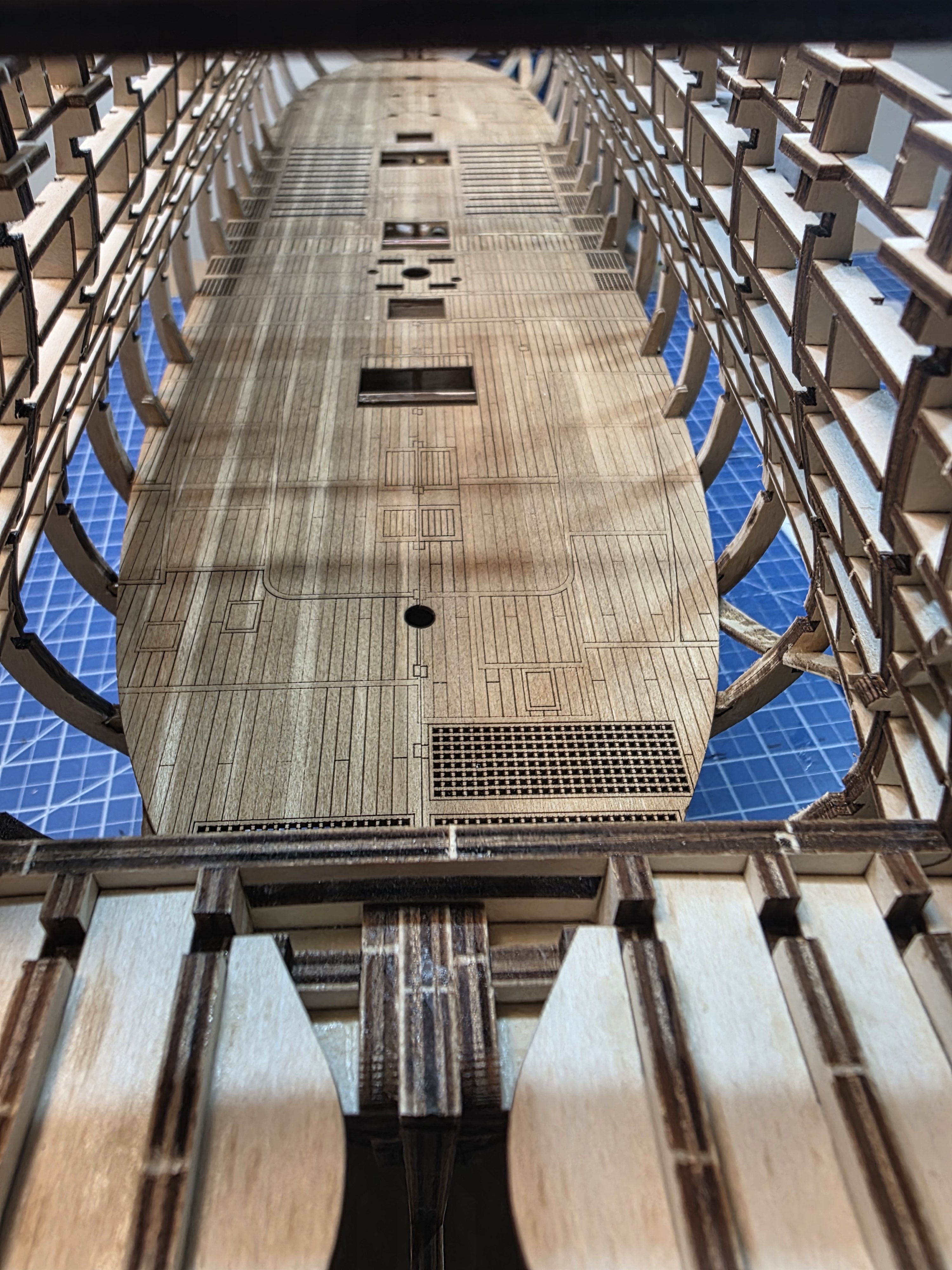
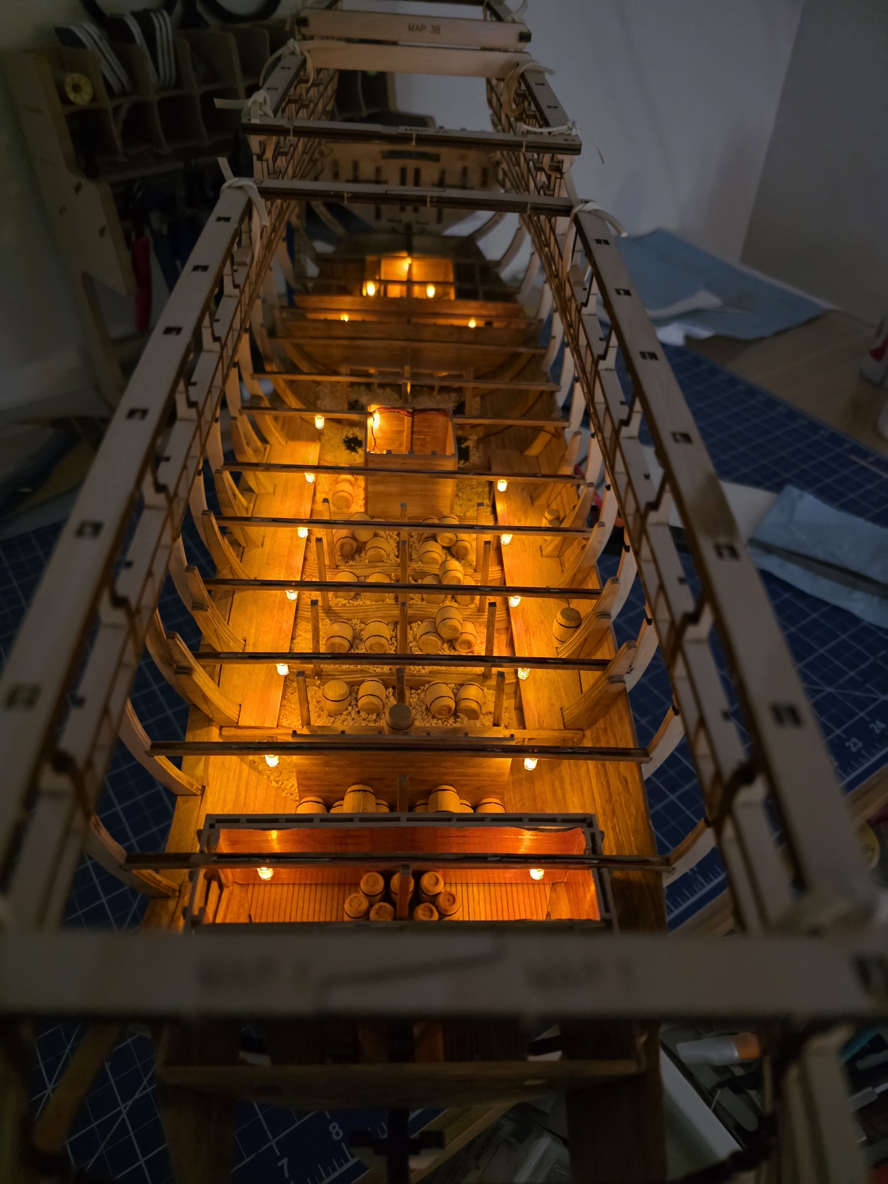
Pressing on with video 10. The orlop deck pieces are installed. The sections/openings all align with each other rather well and with the hold below. Quick mast check shows good alignment for the mast holes and other mounting areas below. I wasn't thrilled with the way the fore and aft sections come together. These little tabs were very fragile. I think I broke at least half a dozen of these during the dry fit. It also took quite a bit of tweaking to get the fore and aft sections to fit together. I ended up gluing some strips to the bottom of the forward deck sections so that the aft sections had something they could be glued to. Otherwise, there was no way to keep them together. Even with that, they just don't go together very well and there are gaps and they don't really align well. The result is not a good look but it is what it is. Other than that, the deck look good. Courtesy hold with LEDs lit pictures.


-
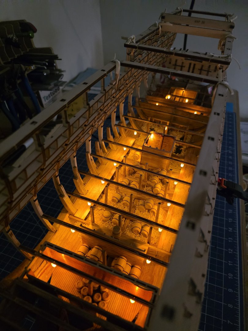
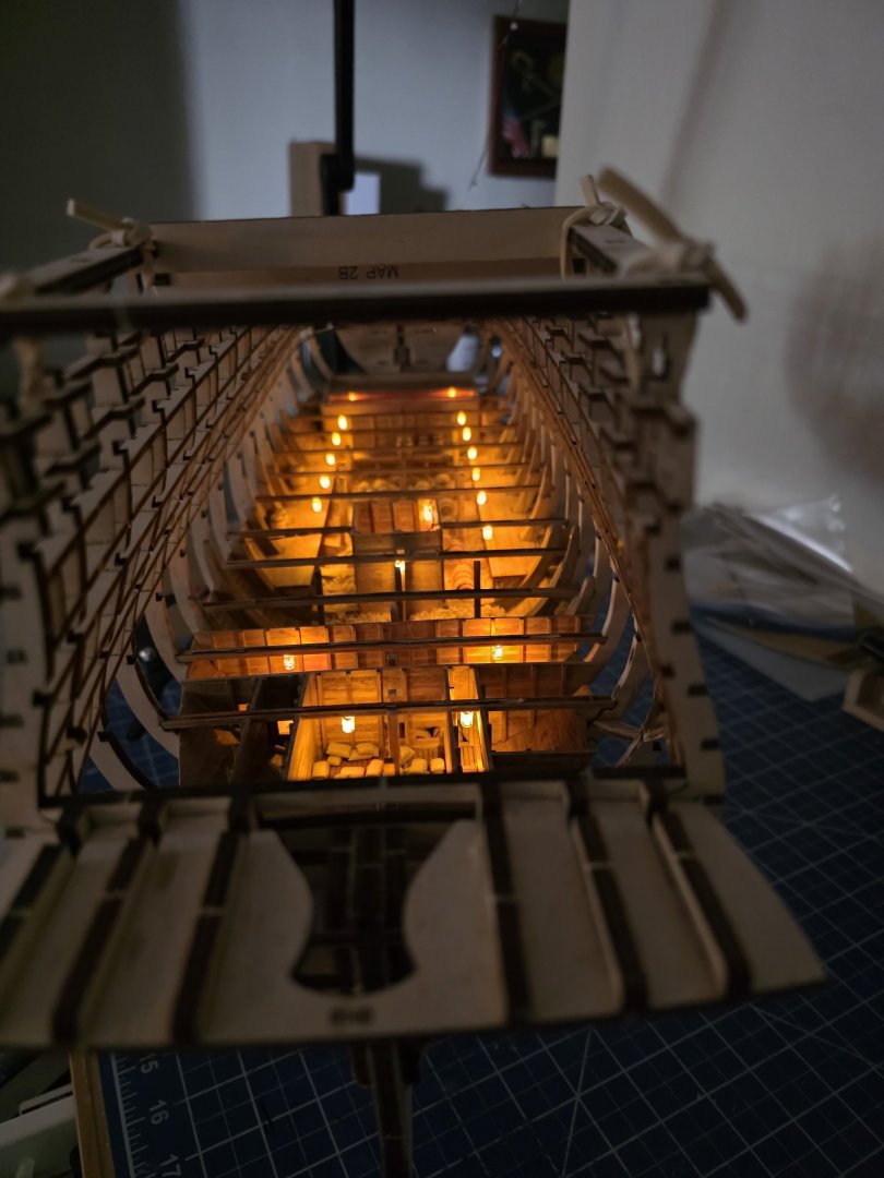
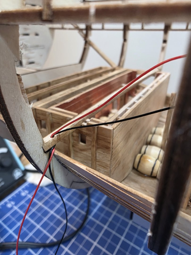
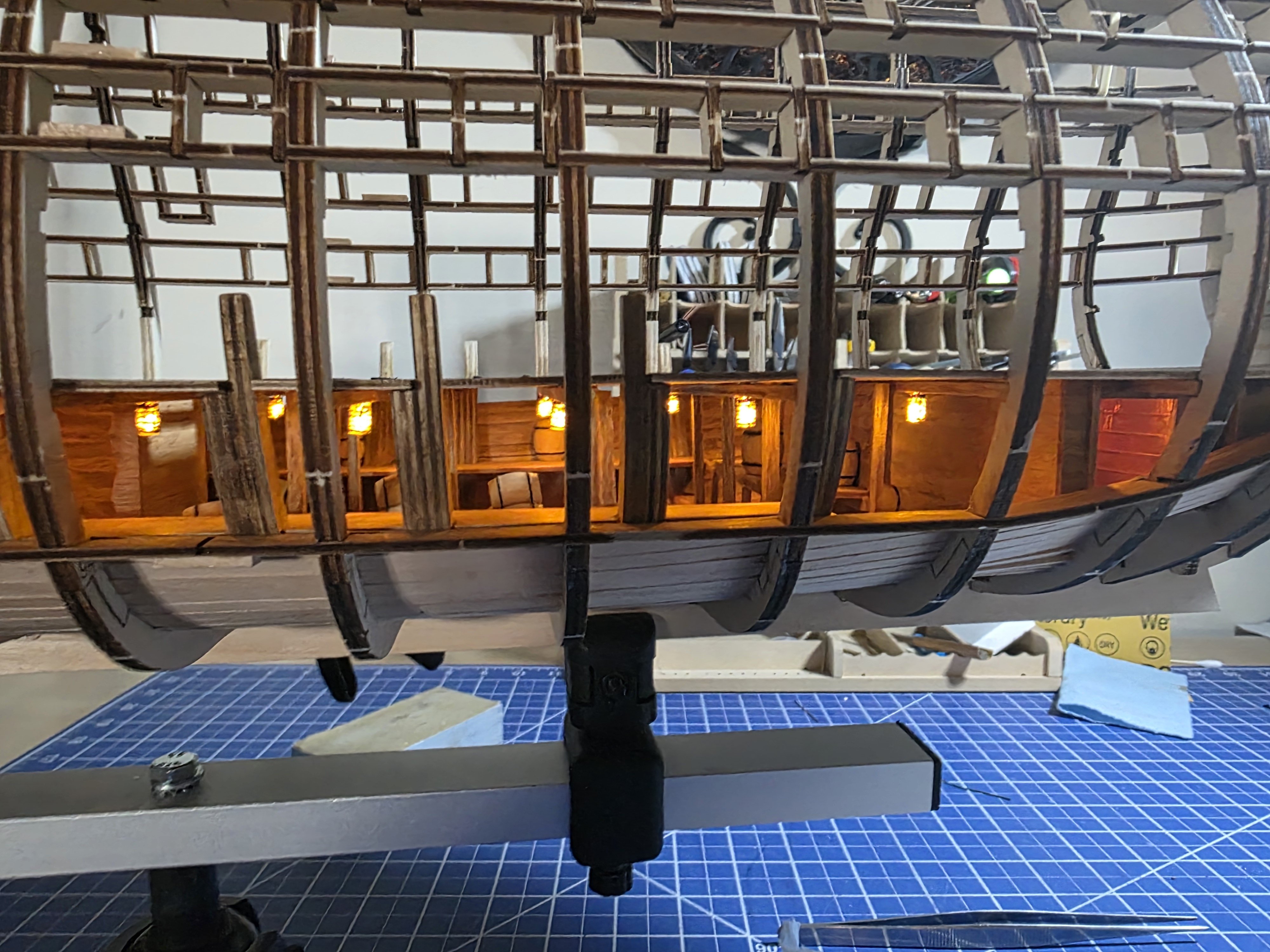
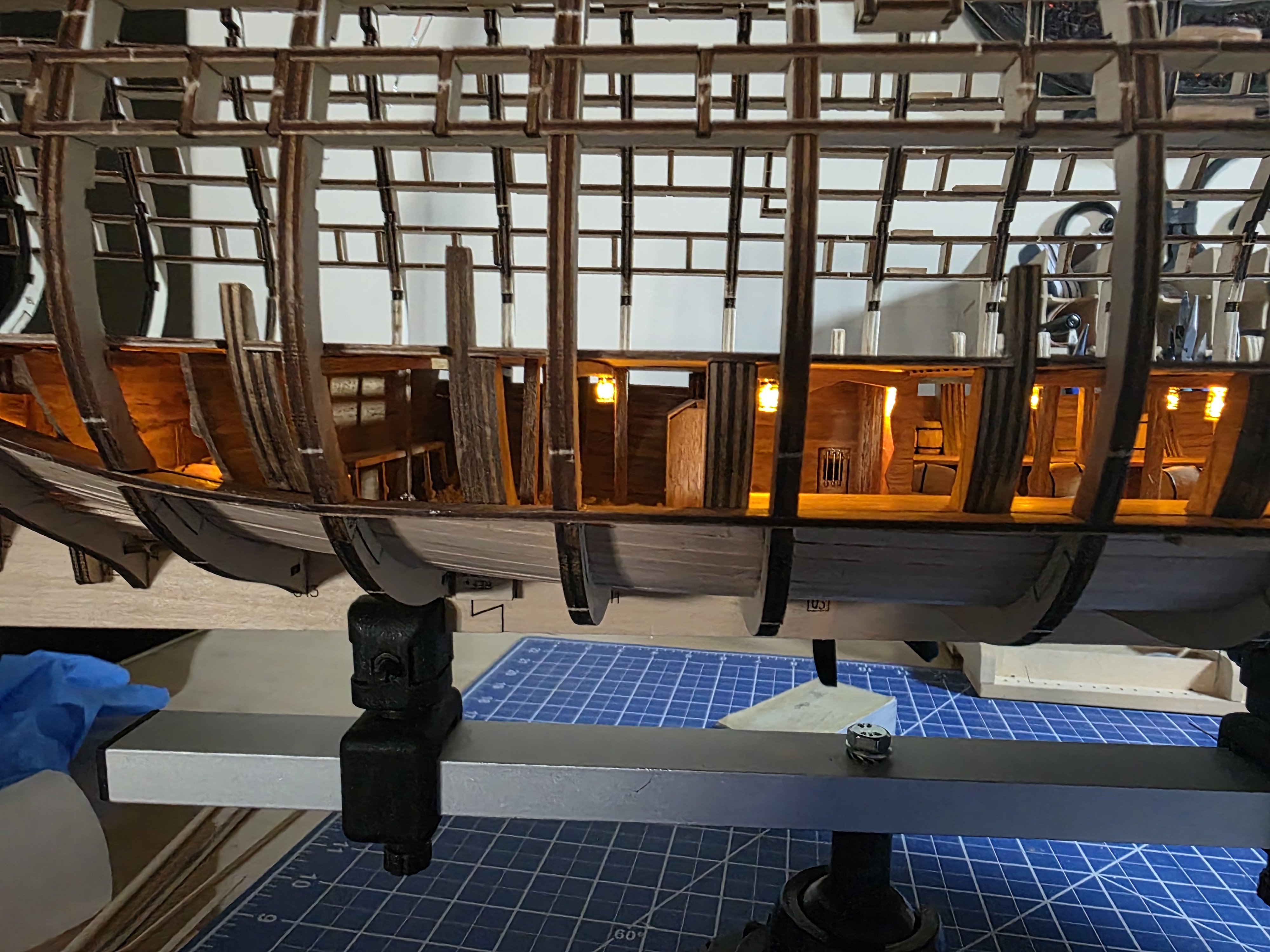
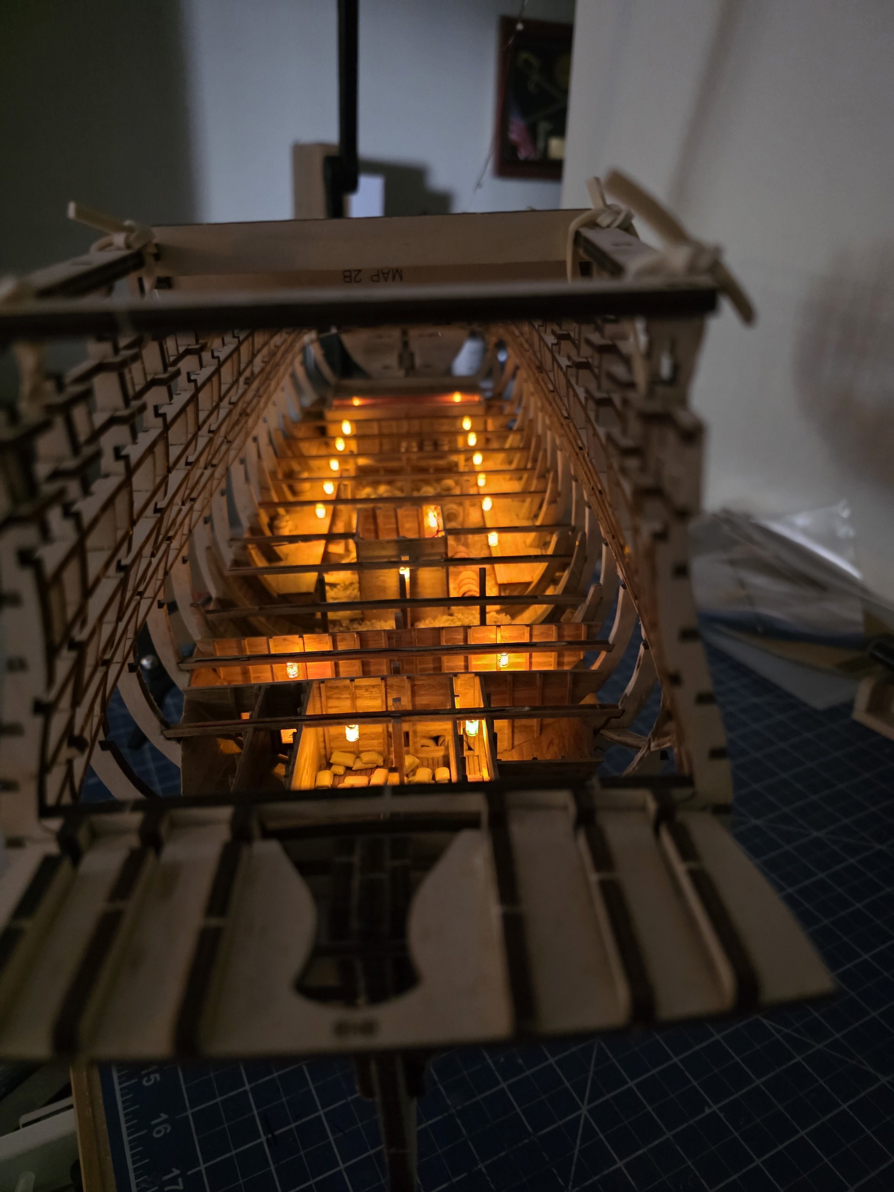
Finally got all the LEDs done in the hold. Took a little while but its not a race I guess. I had a few redos along the way as I wasn't satisfied with the result. Still need to paint a few exposed wires inside to finish up and in the end, no one will know the wires are there. I am now complete through video 9. I think this is a much cleaner result in the end with a lot less wires to deal with. I was hesitant to do this at first, but now that's it done I'm happy that I did. The LEDs really add life to the model. You can see my take on the flour bags here as well. I had to move a few barrels around (second set up from the bottom of the picture) as there are a couple parts that extend down into that area of the hold from the orlop deck. This isn't addressed until video 11. A good set of plans would have been useful in making that known much sooner.


-
QUICK-FIND INDEXES to BUILD LOGS FOR KITS
JeffT replied to Dan Vadas's topic in - Index of all kits by brand and subject
Absolutely. -
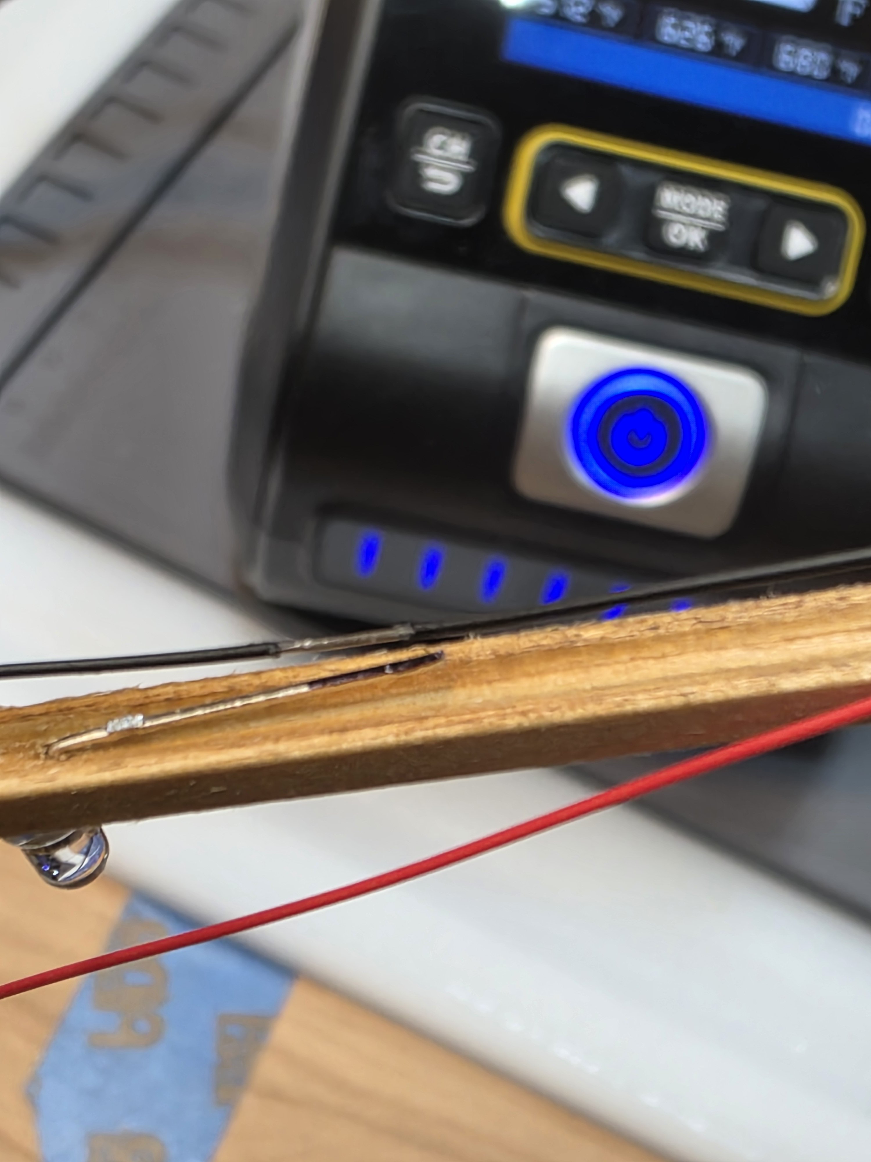
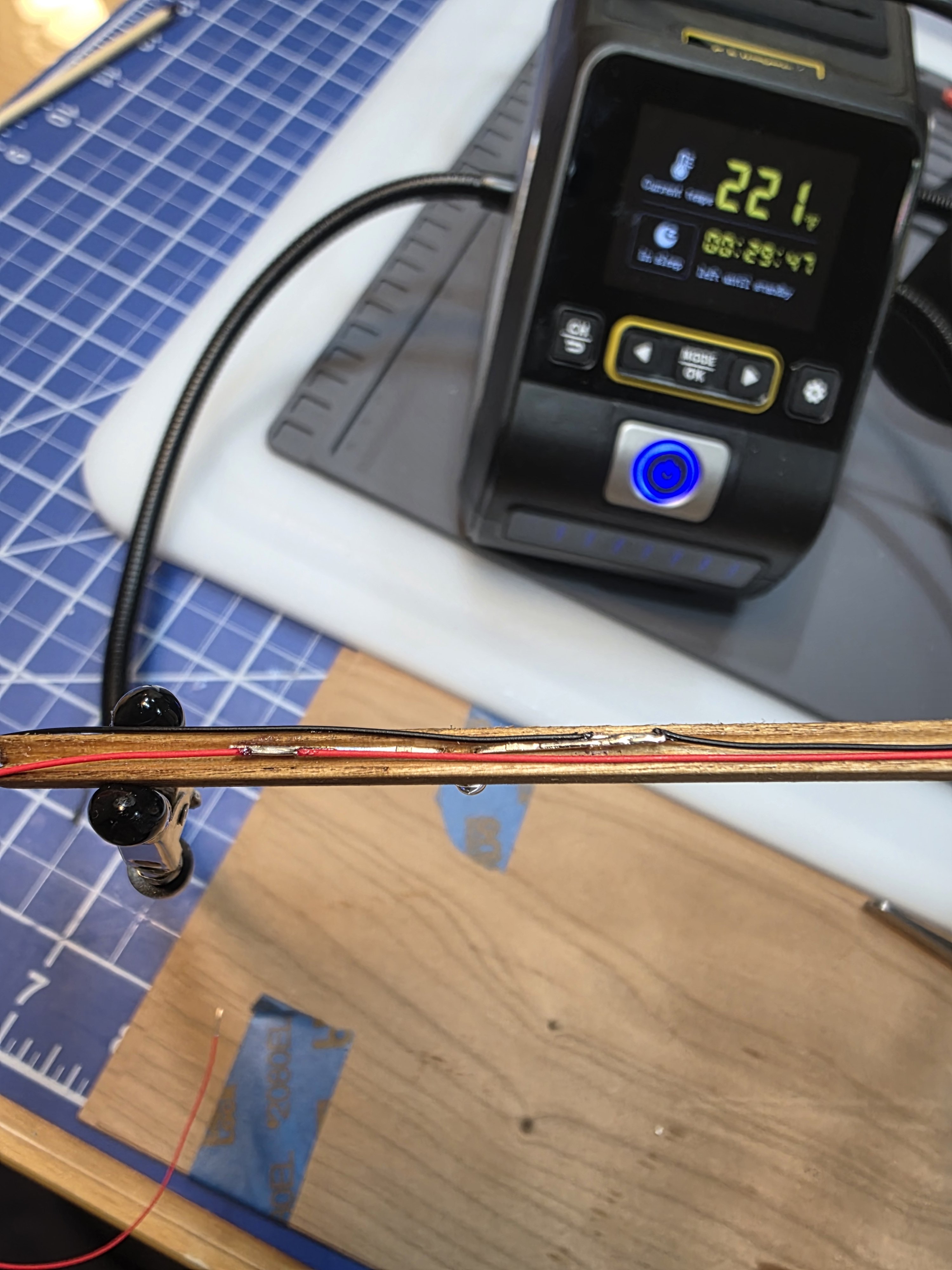
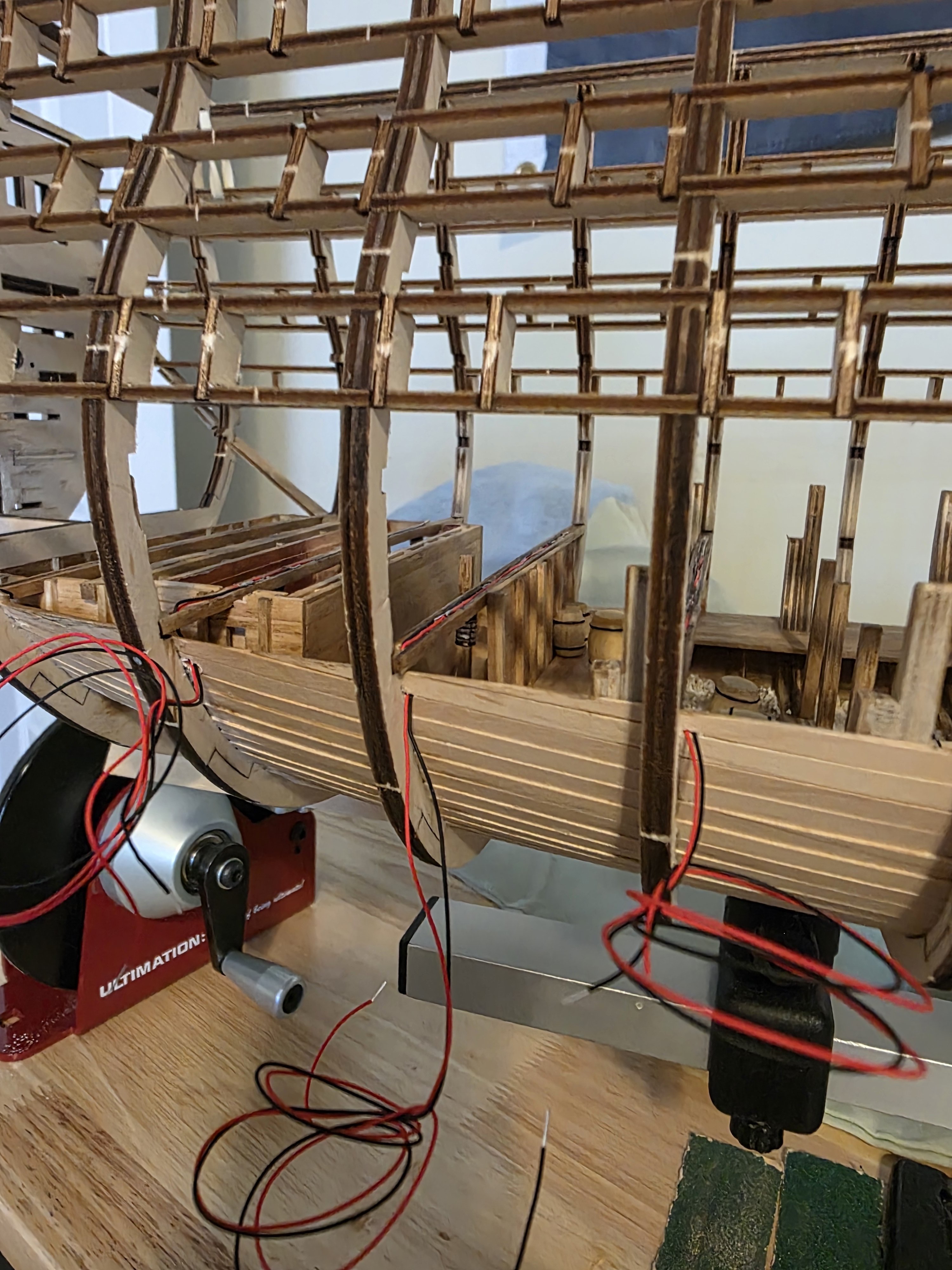
Its been a little while since my last update. I've been watching a lot of videos on soldering and getting a little practice at it. After much thought I have come up with a method of wiring the LEDs that works well for me. I'm using only two wires for each set of bulbs. The AL groove tool doesn't create a groove that is large enough to house the wires and bulb leads, so the groove needs to be widened and deepened. The first thing I do is solder the wires to the starboard LED, trying to solder to the side of the lead. Then, for each wire, I use the soldering iron to burn off some insulation from the wires at the spot where they will be soldered to the second LED bulb. and them solder the wire to the LED. I drill a hole in the bottom of the beam to pass the wires through and then pass the wires through the planking. The location of the wires will make them nearly impossible to see from the open side of the hull and no big holes in the frames. 3 down and a bunch to go. I also stained the deck and added the small strips which are painted black.


-
Excellent work.
-
Something I've been thinking about also. Great job!
-
Agreed! I have a plan and we'll see how it goes.
-
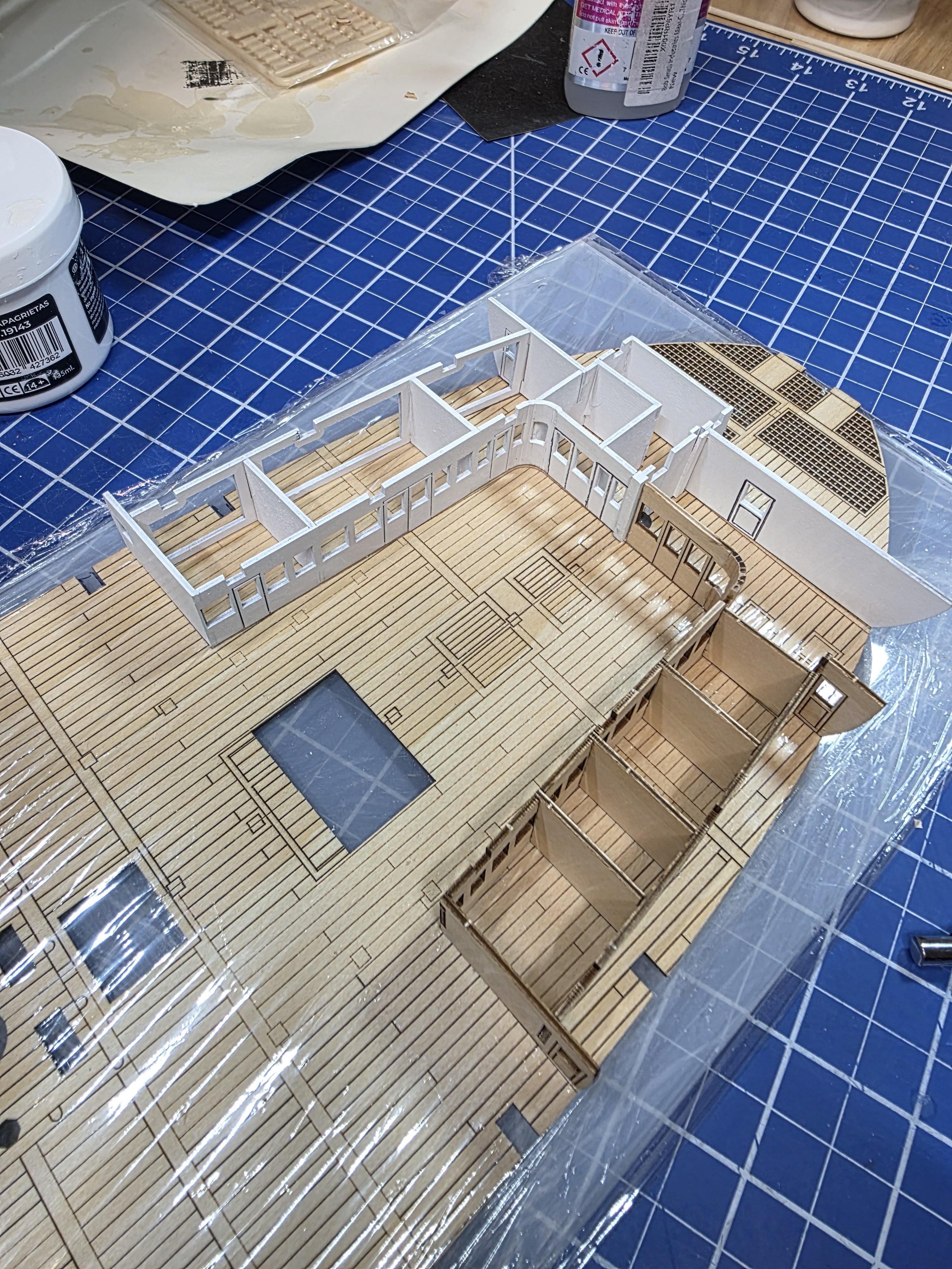
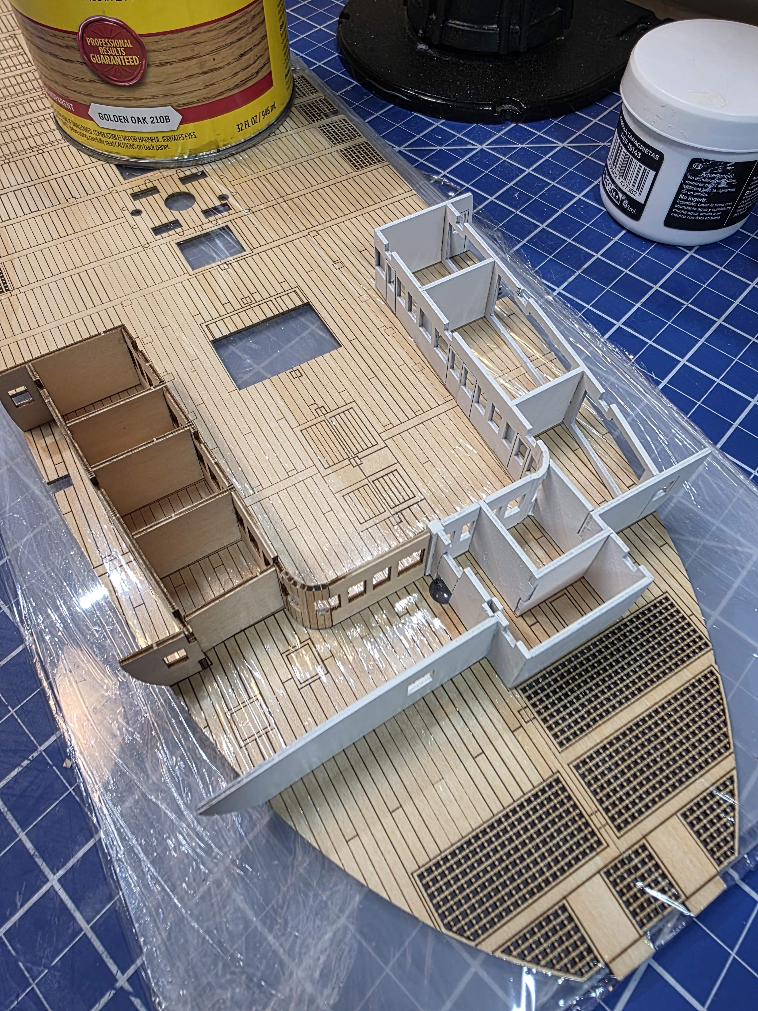
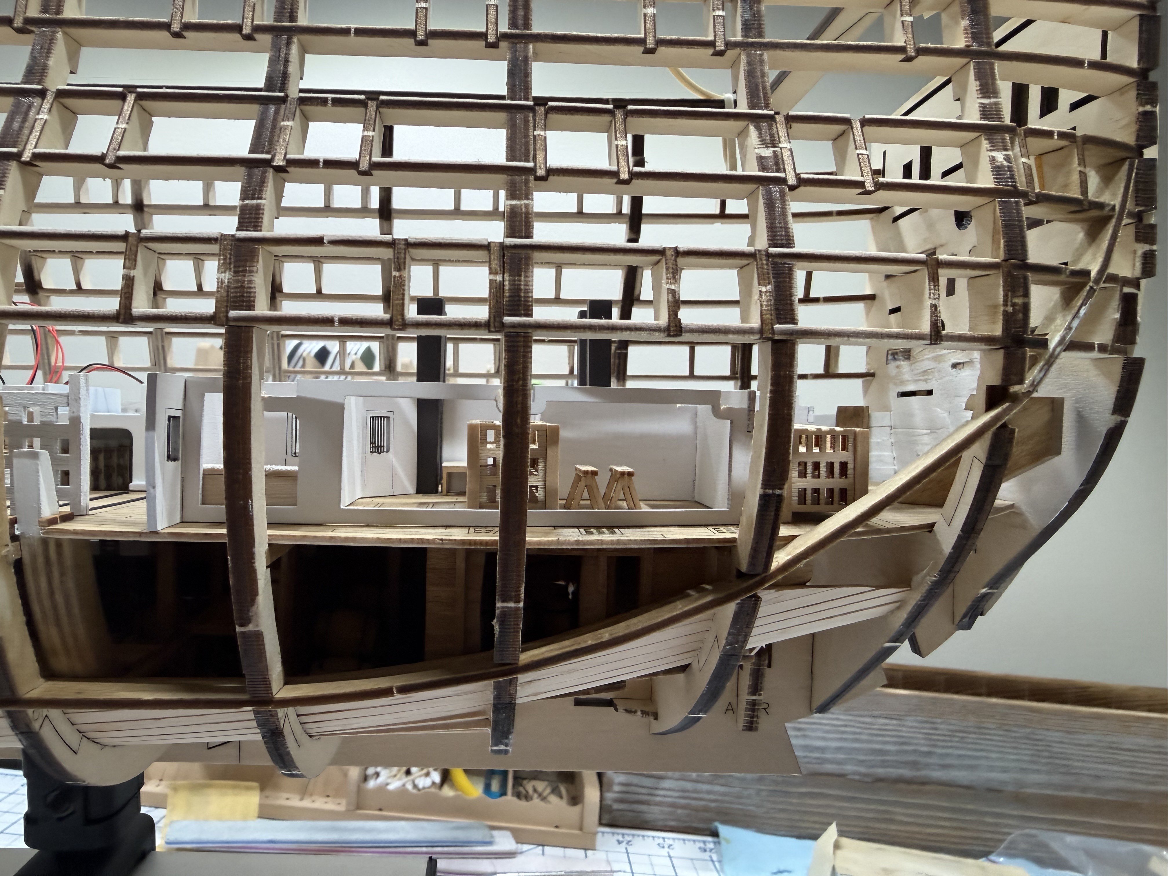
Video 9 is complete. This structure was a bit more challenging than the first one. I have it separated into 3 sections. I feel like it will be a bit troublesome to try and glue this thing down to the deck as one piece. There are a few areas I still need to touch up with white paint yet. Reality is that you can't see much of this other than the extreme right area of the picture below. Moving on to video 10, there are a few more smaller structures to build for the orlop deck. The deck is glued into the model in this video. I'm not ready to do that yet. There are a couple things I still need to do in the hold first. One is the lighting and the other are the flour sacks. Once I finish these last few structures then I'll head back to that. One thing I've done in preparation for the lighting is acquired a smaller soldering iron more suited to the fine soldering needed and some finer solder. I'll practice the soldering a bit on some spare led diodes that I have before tackling that monster. For the flour sacks, I picked up some resin printed sand bags that I think will work. They are a bit smaller than those the kit has you make and seem more to scale to me. I really don't know for sure what size flour sacks were loaded on ships in those days though.
.thumb.jpg.813bd9ce569169e3aa0565cc514ea355.jpg)
-
I should add that I bend the parts before blackening.
-
I appreciate your view. Its really situational for me, Some I paint, some i blacken. I painted the smaller parts, hinges and door latches. One of the issues I run into is the paint flaking off from parts when there is a need to bend the part as with the windows. The primer stays on nicely but the paint layer wants to flake off when I bend the part. With the blackener, I first soak the parts in alcohol for a little while. Then I treat in the blackening agent twice, cleaning in between the two treatments. no issues at all with the color coming off after that.
-
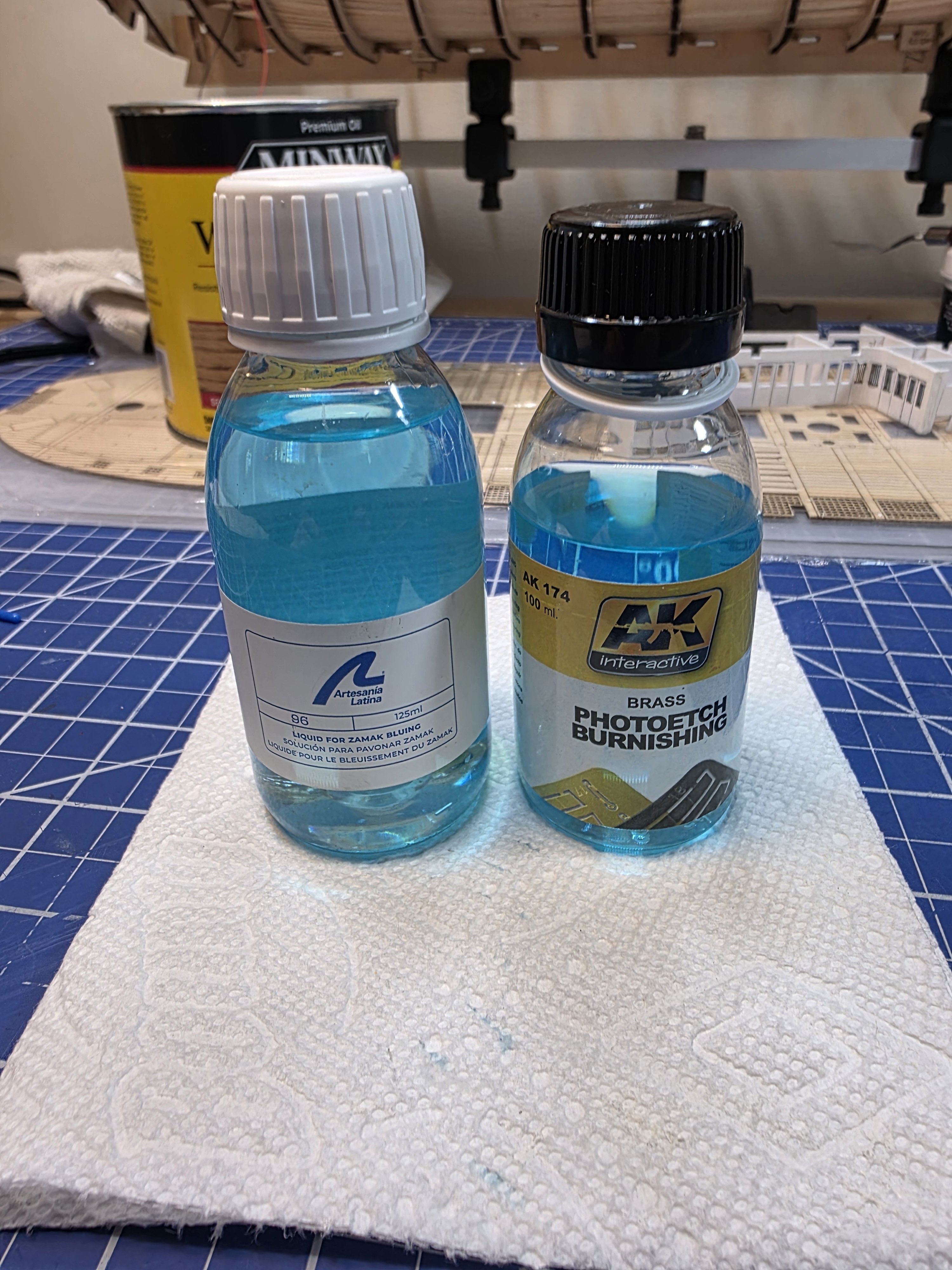
Video 8 is complete. I ended up scrapping the brass black as it was just too messy. I tried a couple of different ones including the Art Lat and AK versions. Both of these worked very well but I leaned toward the Art Lat version as my preference as it was the easiest to work with and produced very little residue. And here is the completed structure. I really struggled with the hinges and door latches as they are very small. It was very difficult for me to see them and so there are a few not well placed. The door latches were so small that I couldn't clearly see how much of the part was the actual part versus the photoetch sheet attaching points. Thankfully most of this will not be seen at all. On to video 9.

-
Not at all. I'm currently trying to learn the software watching videos on youtube. I agree with you. I think that 3D printed parts have a place in ship modeling. I prefer the 3D printed cannons and boats. They look great and the level of detail is very nice.
-
Great news. I never thought I'd see the day.
-
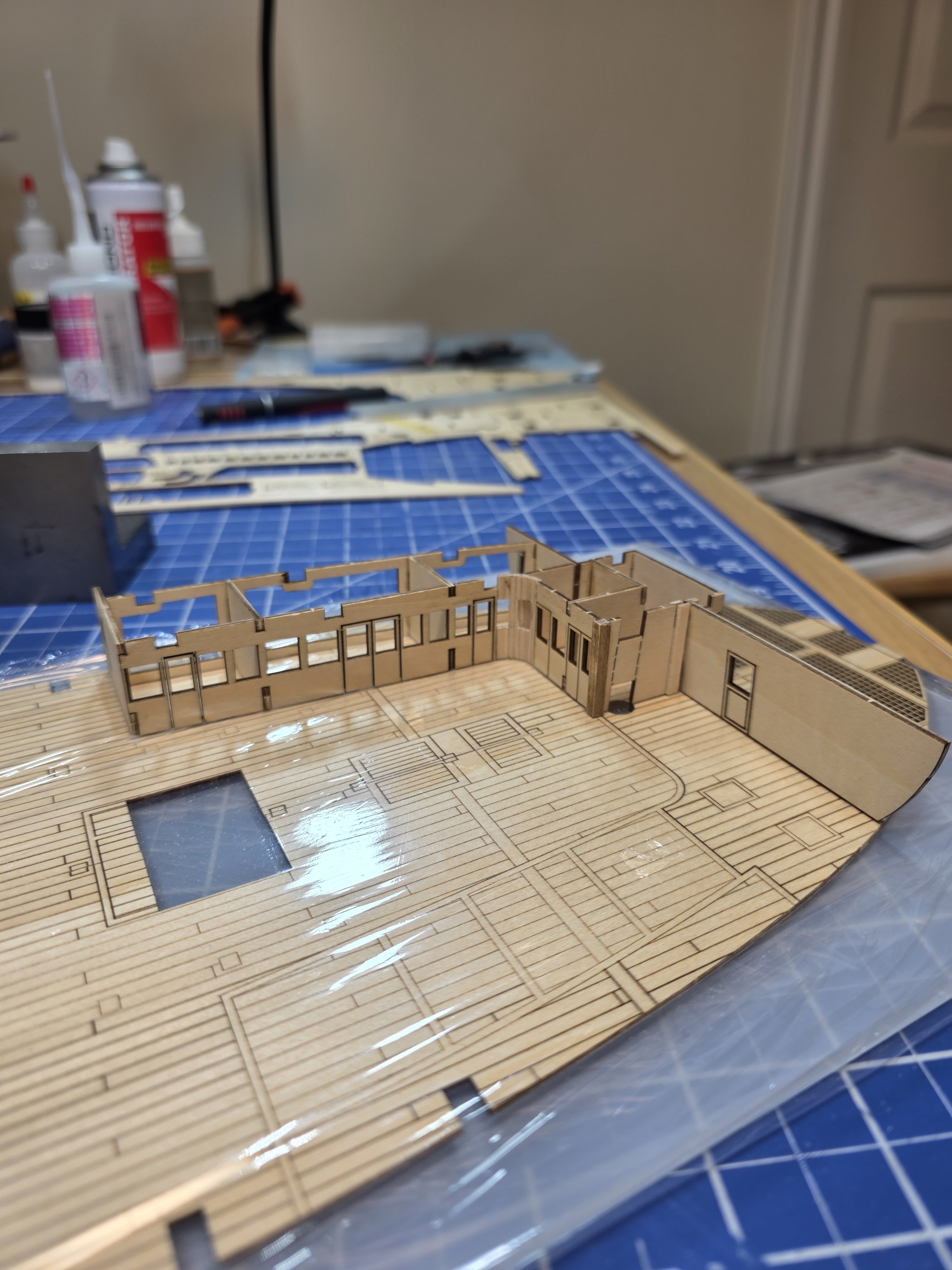
Update. With video 7 on hold, I'm continuing work on the orlop deck structures. Finished the rear section assembly. I decided to keep it separated into two sections until its time to glue it into place on the deck. Just getting started on the windows and doors. I expect this to take a little time because I'm only doing one window/door at a time to avoid mixing the parts up. Which means I remove the part from the photoetch sprue, clean it, blacken it, and then glue it in. This photoetch is very thin so a lot of care is needed as well. I'm using Brass Black to blacken the parts. When it comes to filling and painting, I'm focusing most of my attention on the areas that are most likely to be seen in the finished model. I can see some spots in my photos that some need some smoothing out though.


-
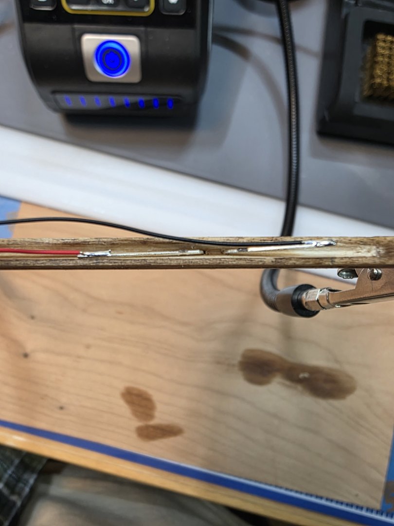
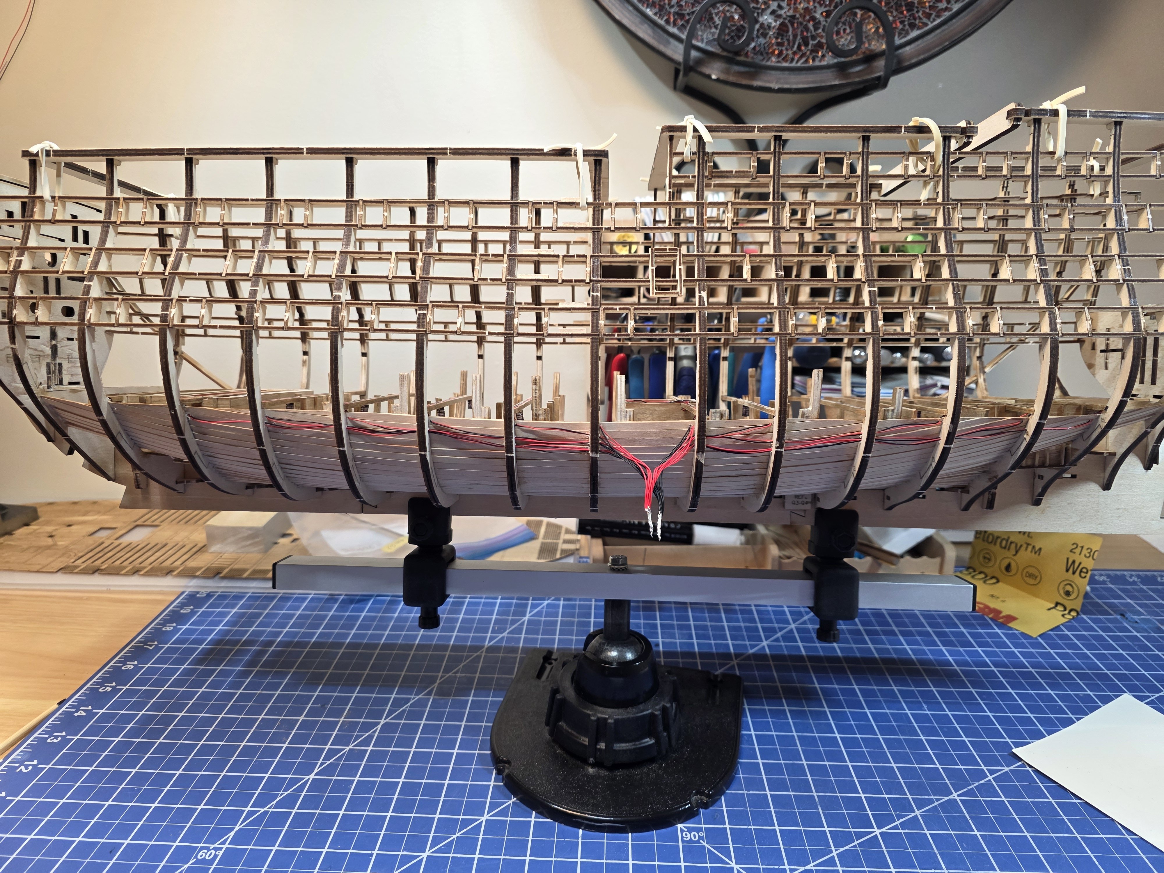
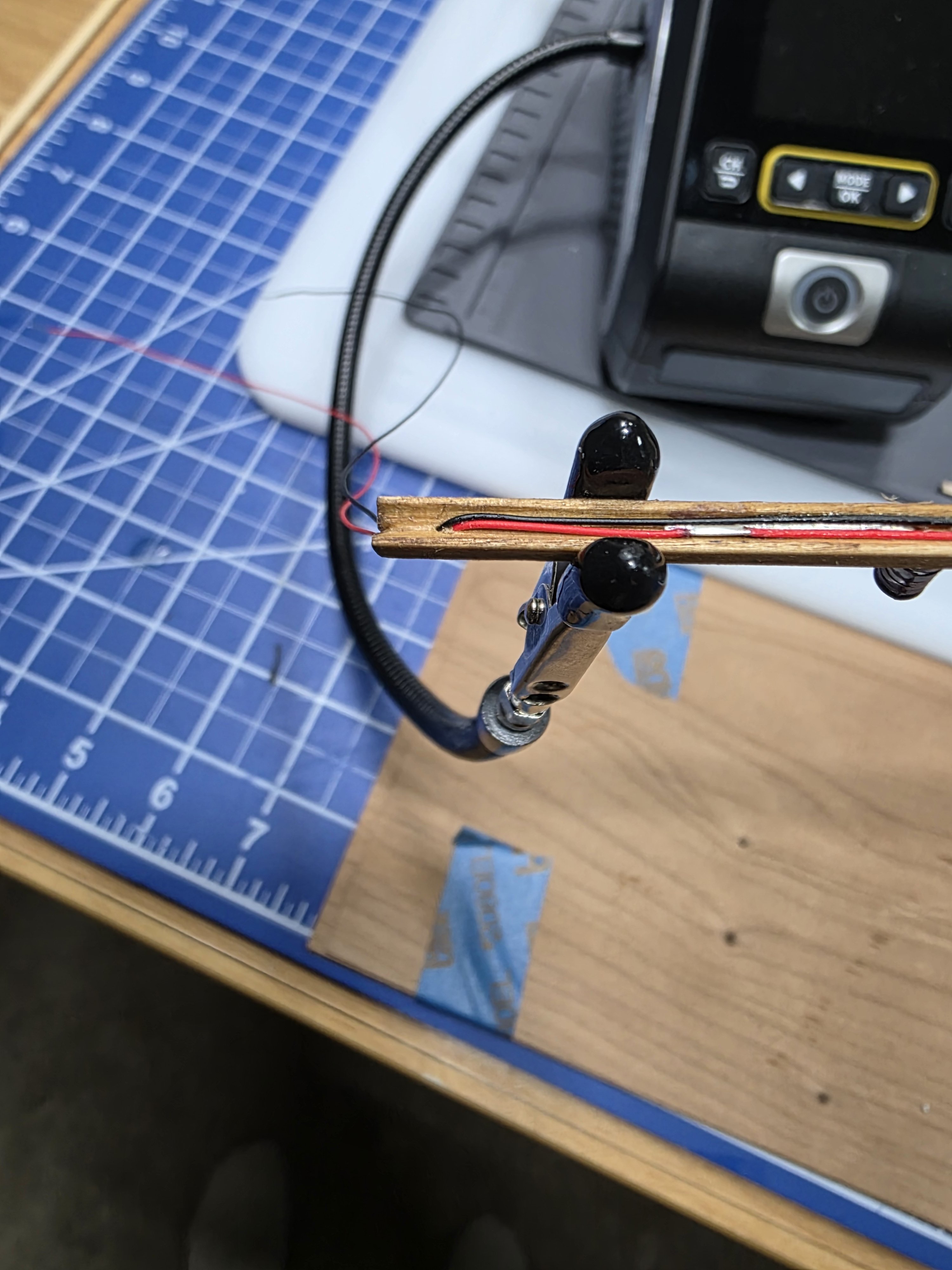
Another quick update. My first attempt to wire two bulbs failed. Its not so easy. The first problem I had is that the groove cut into the beam as shown in the AL video is way to small to support two bulbs and four wires. The groove needs to be much deeper and wider. My soldering attempts weren't too great either. To be honest, at this point I'm considering not doing the lighting at all. Its a lot of effort to go through for something I might turn on one time. Its a cool feature though. I don't really know what the end game is either. Where are these wires going? where will the power supplies be placed? There are two of those, each holding two AAA batteries. There are also 5 switches that need to go somewhere. Quite frankly, I don't really want to search through 80 videos to find out either. I really don't like the idea of drilling massive holes in the frames either. They are already pretty fragile as it is. You can see what I mean in my previous post. I think something like the picture below would work. I drilled a hole down through the beam and then the wire can be routed over the planking or through it for that matter. The amount of wire visible in that case would be minimal and can be painted as well to help conceal it. Keep in mind that this is the closed side of the ship. While I think about whether I will do this or not, I'm pressing on with the deck buildouts beginning with the orlop deck. I think I may build all of the deck structures before committing anything to the model itself. There are multiple structures to build here and thankfully, the parts are laser cut (mostly). There are two curved parts made using a jig and some wood strips, one is done here. This piece ended up being incorrectly sized and I had to add an additional plank to it after removing from the jig. Super easy to break them when trying to cut the windows out as well, so I did the window openings before removing from the jig. Instead of building the entire structure and then filling, painting and adding the photo etched parts, I'm completing half at a time. Its a lot easier to work with this way I think, especially when working with the photo etch. And this is the first half of the rear structure. Sadly, a lot of this will be unseen. This view will not be seen from the open side of the hull. This view is from the side of the hull that will be closed off.


.jpg.fc109b099d3dfacb4240ce808657906e.jpg)