HOLIDAY DONATION DRIVE - SUPPORT MSW - DO YOUR PART TO KEEP THIS GREAT FORUM GOING! (Only 20 donations so far - C'mon guys!)
×


Gerhardvienna
-
Posts
683 -
Joined
-
Last visited
Content Type
Profiles
Forums
Gallery
Events
Everything posted by Gerhardvienna
-
Johnhoward Took some time to read that file, a lot of new things to discover! There is so many information for ALL City-Class interested, I will have to change some things on my Cairo model too! Regards Gerhard
-
High interesting stuff! I will take some time tomorrow to study all of that things and try to bring it to my Cairo model. Thank you for sharing! Regards Gerhard
-
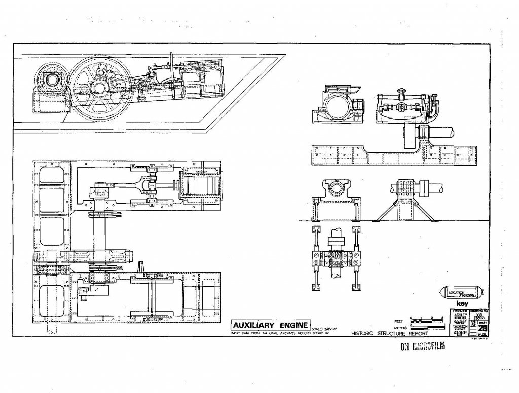
In addition to our discussion about the auxiliary engine I found some time to study the Cairo Historic Report. On page 34 (pdf page 44) I found some hints to the engines. The so called auxiliary engine was used for the capstan and steam driven pumps, as I understand that. https://www.nps.gov/parkhistory/online_books/vick/cairo_hsr.pdf Best regards Gerhard
-
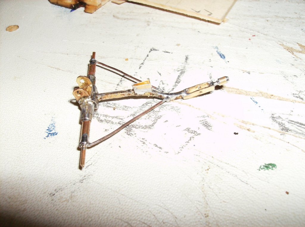
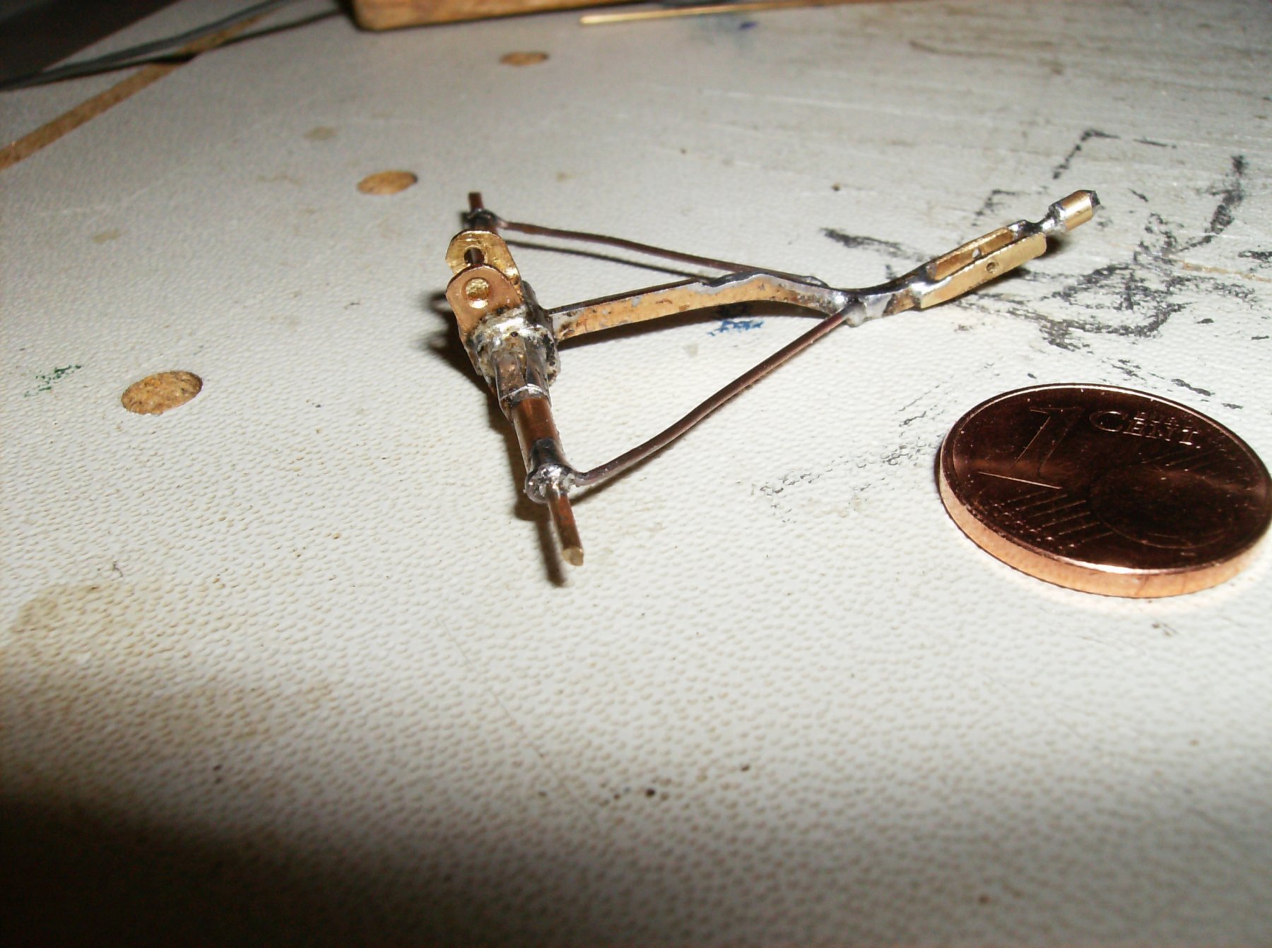
Some more steps done for the small carriage, just the wheels, barrel and the frame for the ammo boxes missing. Thank you for watching Regards Gerhard
- 293 replies
-
- 11
-

-
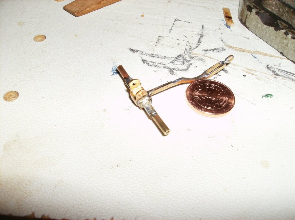
Hi johnhoward This version of the capstan seems to be too far away from the Cairo`s. It is driven by a single cylinder engine, while the suspected engine should have been a double cylinder engine, when I look at the shape of the machine base parts. The only thing I have to find out is where to place that engine. The gearing setup can be adapted for the capstan, no matter where the engine will take place, time will tell................. Best regards Gerhard
-
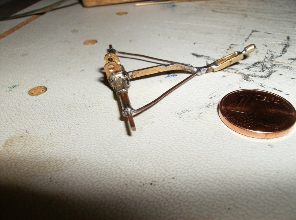
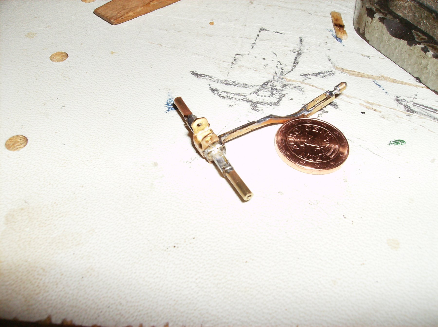
After all that more theoretical stuff it`s time for smoething real. Today I started with the 12-pounder carriage. This is a really small thing, just about 3,3 cm long without the wheels. The main part is soldered from 4 pieces of 0,5mm brass sheet, still some parts missing, but things go on. Best regards, and many thanks for yll your kind likes! Gerhard
.thumb.JPG.7f6f4f01135e29586581669659e69492.JPG)

-
Johnhoward Indeed it is an extra piece of work, to find missing datas for that ships. I`m awaiting all of your research results, so maybe there will be more to come into my model of the Cairo too. But as I`m making a floating model, there will not everything be made after the newest results, but I intend to make all the outside parts correct. Your model will be (and is!) a beautiful piece of artwork, I`m fascinated from it! Regards Gerhard
-
Hi Gerald This is really helpful! So I can make my choice for the boats, and maybe start with one of them! Thank you Best regards Gerhard
-
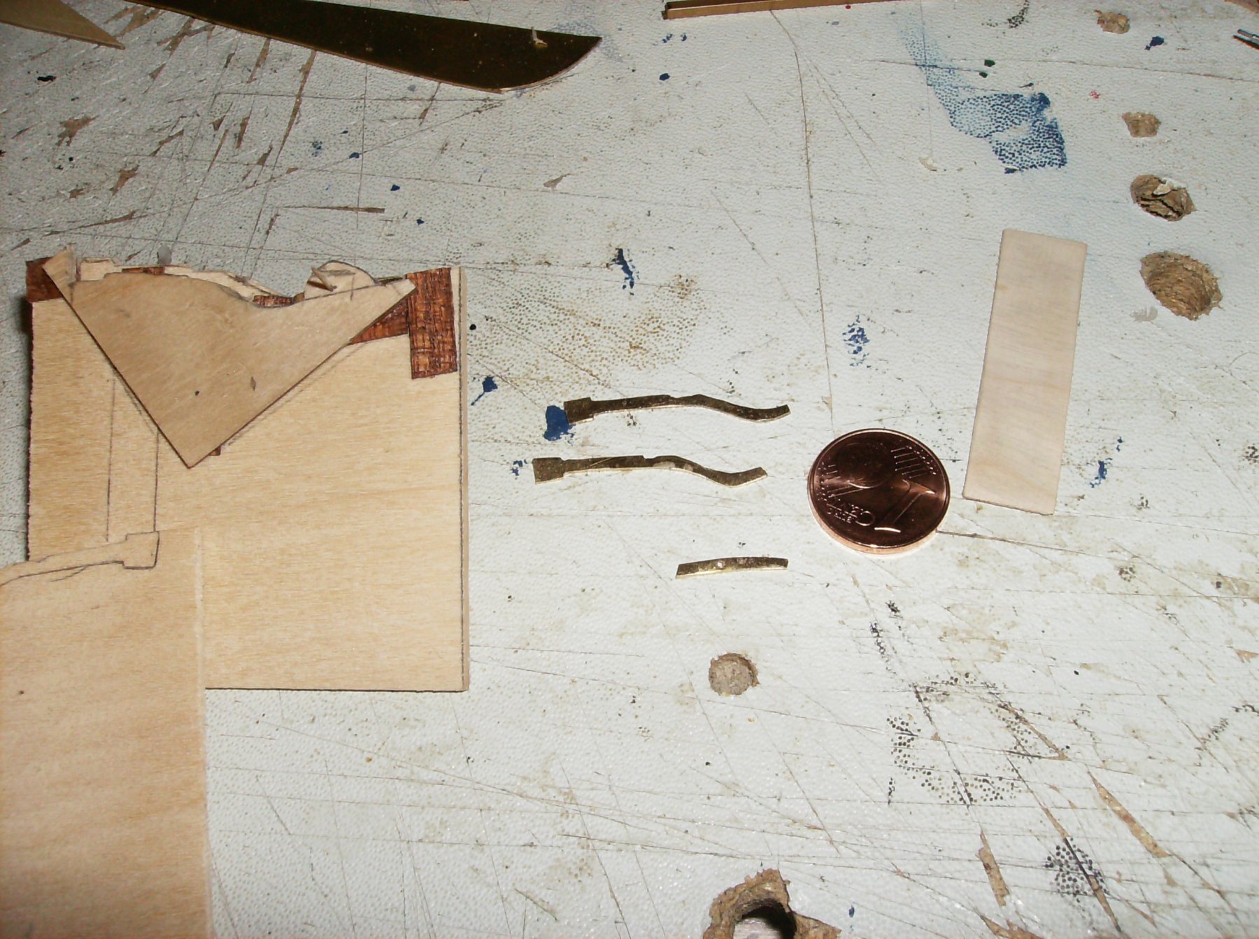
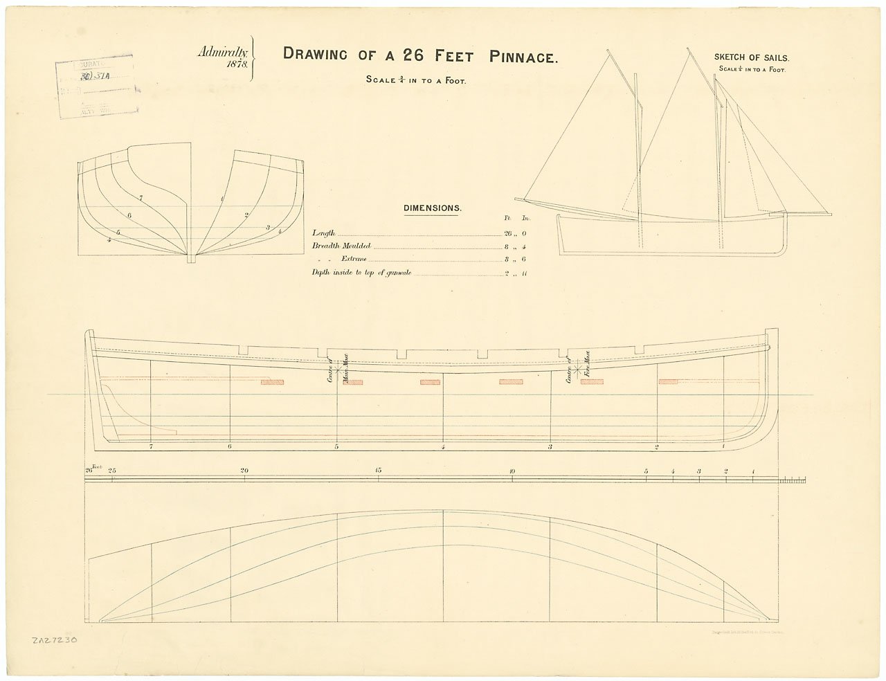
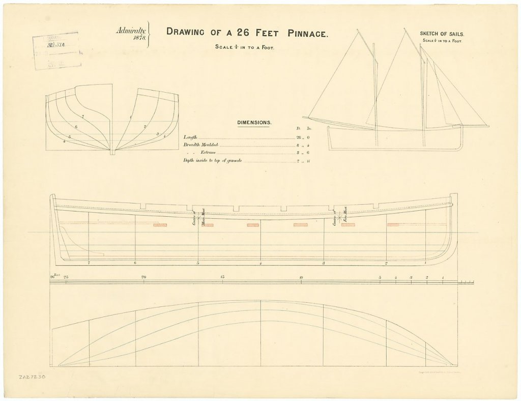
Hi johnhoward EVERY hint helps, Thank you! By studying the sketch above, this could have been a 26ft long cutter. I found one pinnace at the NMM Greenwich collection, wich will be around 16 cm length in 1:50 measure. even the shape comes close to the drawings, but the boat is a bit younger, from 1878. But I expect that there were not so much changes in shape on such boats, so I will go with it. Just the one Launch is still what I wonder about length and shape. By searching for "Bristol Boats" I fell over the Atkin&Co Site, they show a good drawing for a 15ft 6in. boat, even similar to the Cairo drawings. http://www.atkinboatplans.com/Oar/BruceConklin.html Best regards Gerhard
-
I`m doing my best, therefore are so many requests I have to make. Still one more, what size did the ships boats have? Soewhere I read about 2 different types of boats, see the pic. I just dont know at the moment where I found this Hi Mark That`s what I`m afraid of, that a lot of things simply disappeared for some reason, and is lost now maybe forever. Regards& thank you all for stumbling in Gerhard
-
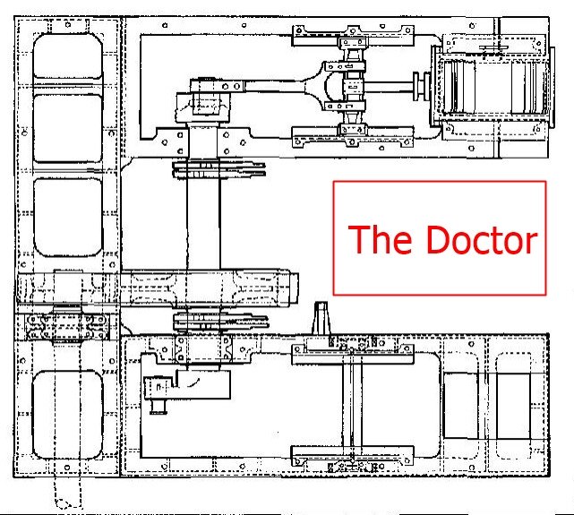
Hi johnhoward So this all brings me to the conclusion: i will build the doctor close to the boilers as you did show in the Paddlewheel attachment. The auxiliary engine is not to locate, but will be built in too, I will search for the location of this engine, maybe I will make it as you did show earlier, with a connection to the capstan. This WAS steam driven, when I read, what the Vicksburg museum page tells: https://www.nps.gov/vick/learn/historyculture/capstan.htm So a lot of open questins are answered in the last few days, Thank YOU Sir! Even the 12 pounder is now good to locate and to build as a model, so a lot of "extra" work will be made Best Regards Gerhard
-
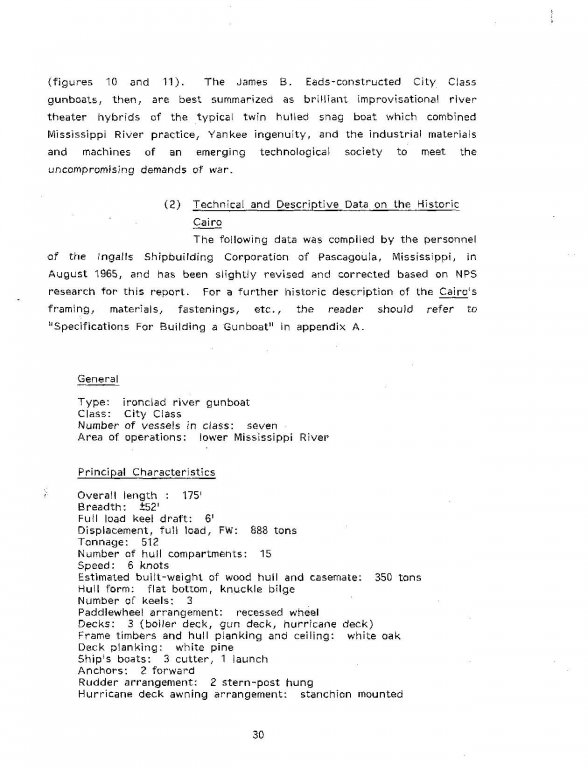
Beneath the studys about the second auxiliary engine and the 12 pounder I made another gun barrel ready for 3D printing. This time is was the Rifled Army 42 pounder, 3 required for the model. Regards, and many thanks for watching Gerhard
-
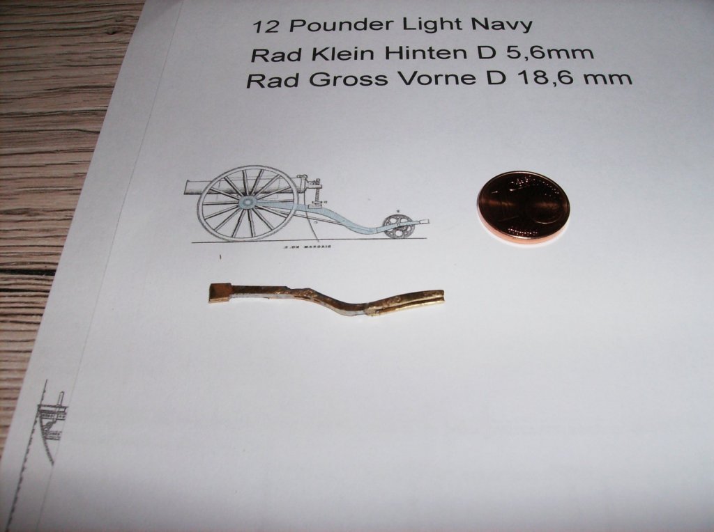
Hi Roger In addition to the books you mentioned (I have them both downloaded months ago...), i found another one, which shows the carriage for the 12-pounder best in side view: http://www.civilwarnavy.org/?page_id=321 Best Regards Gerhard
-
Hi johnhoward Found both books by googlesearch, interesting things to learn for me. As I have learned more in the past few days than in years before! So the doctor should be built in but turned 90deg. not as Gene Bodnar did show it in his Cairo model: http://www.modelshipbuilder.com/e107_plugins/forum/forum_viewtopic.php?5406.60 When there was no power assisted steering, the other auxiliary engine will have one reason only, to assist the capstan? If we (or you) can find out, where to locate this second auxiliary engine, I will make it too, just for the reason it was there! Regards Gerhard
-
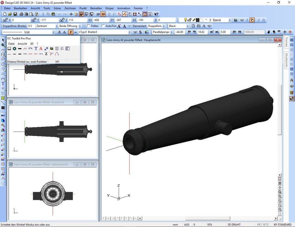
Hi johnhoward Thats what I found out by scaling the drawings to same measure. The so called auxiliary engine would have been far larger than the driving engime. I thought, that the auxiliary engine could have driven the capstan and MAYBE the steering, as it was done on different (german) river tugboats, while the Main Auxiliary Engine "the Doctor", was used for filling the water boiler. If that scond auxiliary engine was used for steering too, this could declare the giant size of it. But in the drawings I did not find any hint for that! So there is a lot more to find out how they have built the ship, and how they managed to steer it! The fire room did probably not have enough space for an extra engine, so the place of it could have been "around" the Doctor, or at one side of the vessel in height of the capstan. The plansheet I`ve shown before shows the top view of the engine, there you can see a rod to port side of the engine, but unfortunatly not further parts of it. So we will have to speculate, how the parts we know did work together, and what parts are missing! To illustrate what i mean I`ve made a little sketch fron the auxiliary engine with the Doctor as a simple square set in. Best Regards &Thank you for your worthful help! Gerhard
-
Hi johnhoward So I could go with the carriage from post #151 exept the lighter wheels. Measures are good to see in the markerhunters article https://markerhunter.wordpress.com/2011/01/17/dahlgren-12-pdr-small-bh/ Many thanks for your help! And another request too.............. In the plans from Vicksburg I could see, that there were a Two Cylinder steam engine named " Auxiliary engine". Wher the he..... was this built in, location was shown as unknown, whe I followe the plans! Regards Gerhard
-
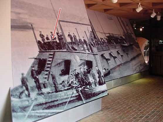
Johnhoward When I compare that pics to the photo from the Vicksburg museum entrance, I`m not sure what carriage they used for the 12 pounder. Could be possible too that there was a wodden carriage similar to the sledgelike boat carriage in your post above. Does anyone live near Vicksburg who could take a close look (and photo) from that entrance poster? Sad that it`s such a long way from Vienna/Austria/Europe to the museum Regards Gerhard
-
Hi Roger Took a look at them now, good stuff for research, maybe I`ll order some of them! Thank you for advise! Regards Gerhard
-
Hi Gerald By watching the photo I posted on the previous page, I`m sure that the CAIRO 12 pounder had the Naval Field Carriage. Thank you for bringing a bit more of clearness to this part of the ship, most useful pictures! All necessary measures can be measured otu from the pics for a good model, so I can start with the smallest Cairo gun too. Best regards Gerhard
-
Johnhoward, Thank you again! Seems to be this one I found in the meantime by searching at google https://markerhunter.wordpress.com/2011/01/17/dahlgren-12-pdr-small-bh/ As there is a listing of the different measures I will be able to build it correct for the Cairo. Carriage and wheels will be made from brass, the barrel 3D Printed or turned from brass. Great hint! Regards Gerhard
-
Hi johnhoward Great infos about that, thank you! I`ve never watched this photo so close, but I think I found the 12 - pounder on the hurricane deck of the Cairo.... Source: https://www.nps.gov/vick/learn/historyculture/images/museum-entrance-mural.jpg Now I have to look for better photos or drawings to make even that gun correct! Best regards gerhard
-
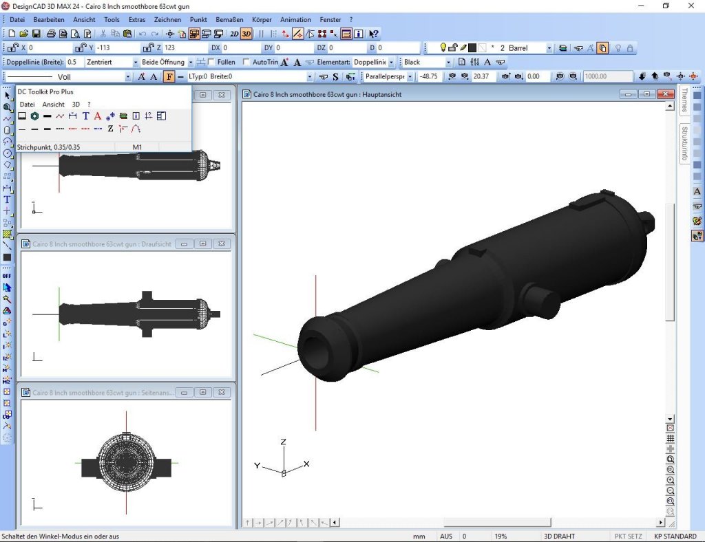
Hi again, and many thanks for all of your nice likes! While I was waiting for the wood delivery, I made another 3D Part, the barrel for the 8inch smoothbore guns. Three needed for the Cairo, will take some time to print them. Best regards Gerhard
-
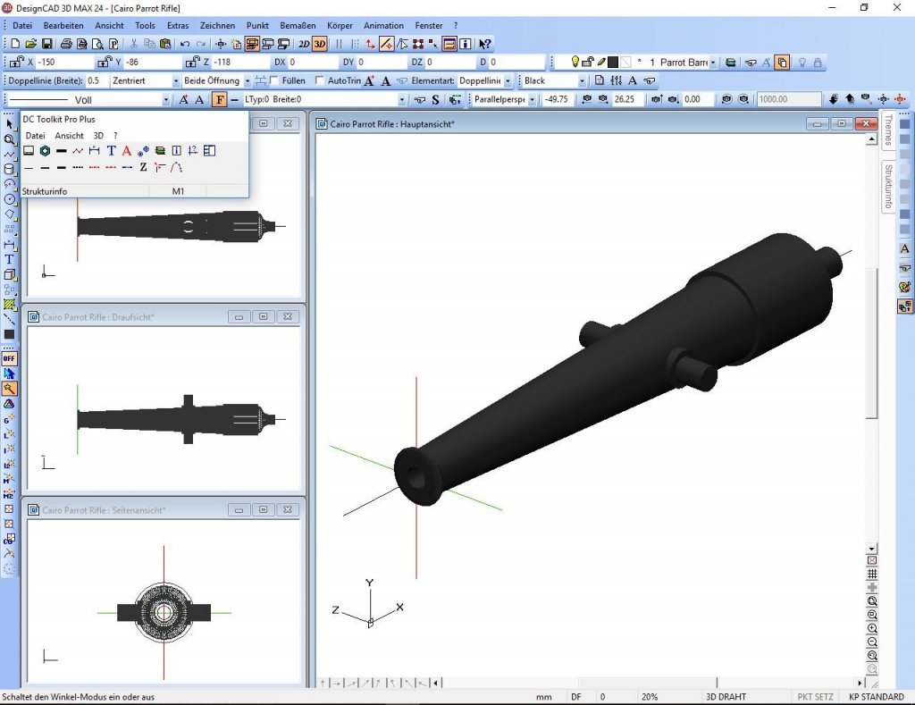
Hi Popeye Yes, it is. But I`ve been working on my 3D Program to get the first Gun barrel ready for printing, the parrot gun is done. Not sure what kind of filament I will use for the barrels, but tending to Black PETG or ABS. Time will show, when the printer is built, maybe in about 4 to 5 weeks. Regards Gerhard
-
By writing about making the Cairo as accurate as possible (for a RC-Model!), I learned on Wikipedia, there must have been a 12-pounder rifle aboard. https://en.wikipedia.org/wiki/USS_Cairo BUT: There is no info where it was located on the ship! Can anybody help me in that reason? What kind of rifle was it, and where to place it! This item does not appear on any plans I know! Thank you in advance! Regards & many thanks for your nice likes! Gerhard
-
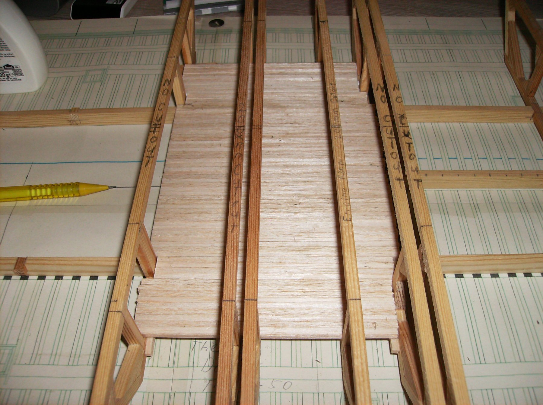
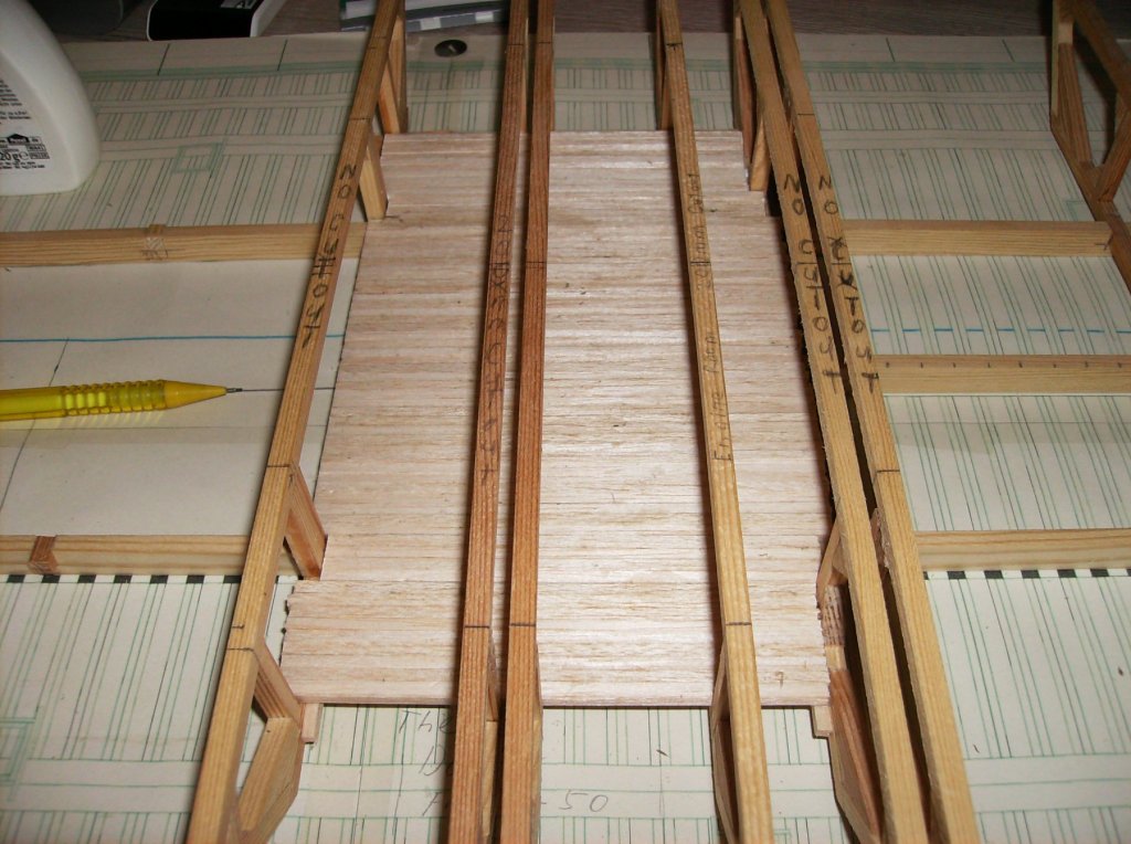
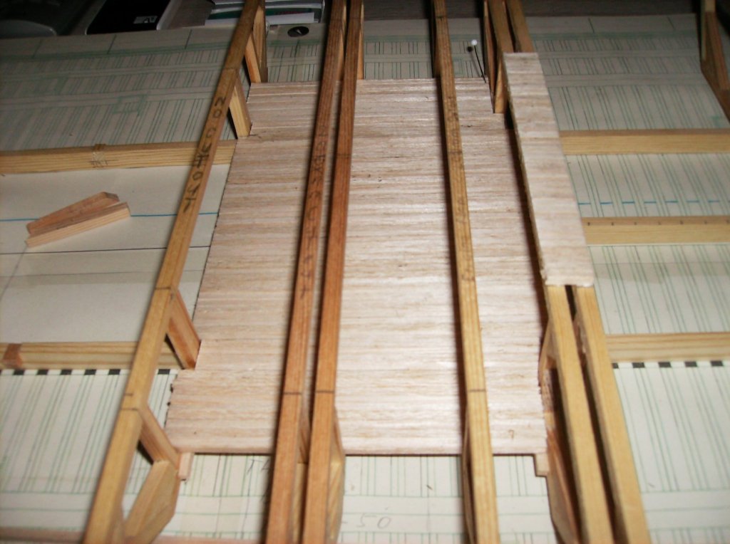
Hi Johnhoward Would be great to see what changes are to make for an accurate model. The guns and their carriages are important to me, but the most of "invisible" interior parts are not so important for a floating model. This will be more important for a showcase ship. I need most of the inner space for the engine and the RC-Stuff. As far as I am at the moment, I still can do some slight changes, as long as it is for the casemate, and the rudder/steering unit. The paddlewheel should too be as close as possible to the original thing for its visibility. I have signed in for your St.Louis building report, so I will not miss anything from that! Hi to all interested too. Some progress made this days, small portions for the floor are done. But still a long way to go! All the cutouts in the frames will be done when the deck is finished and all the "boxes" for the engine and RC components are set in. Best regards, thank you all for your interest Gerhard
- 293 replies
-
- 10
-

.JPG.11a45161196d11292eda3c9c17b216f7.JPG)