
HOLIDAY DONATION DRIVE - SUPPORT MSW - DO YOUR PART TO KEEP THIS GREAT FORUM GOING! (Only 24 donations so far out of 49,000 members - C'mon guys!)
×


RichieG
-
Posts
114 -
Joined
-
Last visited
Content Type
Profiles
Forums
Gallery
Events
Everything posted by RichieG
-
ha! brought to you by poplular demand indeed! As you know, I'll be following along with this build, as I do my own in my newly private log. I feel like I just kicked out my roommate and I have the whole place to myself I haven't received the new parts yet, but it should be within a few days now. I'll let you know.
-
Al, I think Tigersteve makes a point; it's obvious enough to you and me who's model we're talking about or posting pictures of, but to everyone else, it might be confusing to keep track of two builds on a single post. If you make your own build log, I promise to check it out regularly and comment on it (if just for my own benefit.) So, last I posted photos on my build, I still had two thwarts left to add to the ship's boat. Joel got me thinking that using paper or card stock templates might make cutting those irregular shapes out of the wood strips easier, so I made a couple of card stock templates for the last thwarts and then used them to make the wooden pieces. It was a good idea. (I have a photo of the card stock in place, and then one with the wooden pieces.) Then comes the clinker-style planks. The instructions make them optional, and do mention that they are tough to do at this small scale. I'll agree with that last part! I first tried to make paper templates for each of three planks on one side. That alone was hard, because I had a lot of trouble keeping the paper in place. I tried card stock and tape, regular paper and tape, and settled on the adhesive part of post-it notes. The post-its worked best but still were far from easy. I have a photo of the three paper templates, with the top plank on top. As I progress to lower parts of the hull, the plank shape gets increasingly distorted, with the ends curved more and more downwards. I then used these paper templates to cut 1/16" wide planks out of 1/8" wide stock. But first, I had to thin the stock down from 1/32" to 1/64". I started by rubbing it back and forth over a piece of 120 sandpaper, but as the pieces got thinner and more delicate, they had a tendency to break on the 'push'. The technique that ended up working for me was to put sandpaper face up on the table, and pull the plank in only one direction, between my finger and the sandpaper, applying gentle downward pressure. This way it didn't break the pieces when they got thin, and some of them even developed a gentle curve which was going to be useful when the piece was to be applied to the hull. Then I cut the shape of the paper template (the stickiness of the post-it adhesive worked well to stick the paper to the wood) and then gently curve it over the hull. I used a compass to draw the tops of the second and third plank (first plank was to be at the top of the hull, the second was 3/64" lower, allowing for a 1/64" overlap with the plank above, and the third plank would be 6/64" below the top, also allowing for overlap.) Suffice it to say, it was both easy and hard to work with such thin planks (they bent easy, but they were pretty delicate.) I did resort to CA glue at the ends, and wood glue along the main course. I have a couple of views of the finished product. I think I can trim some of the planks after they're in place to make it a little more aesthetic, but I'm going to let it sit for a little while before attacking it again. Now I just have to do the other side, and then I can glue on the stem, stern, keel, and cap rail.
-
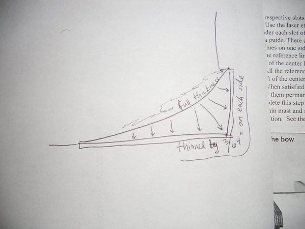
Al, look at page 2 (the first text page of the manual), and check out the picture in the upper right. First, make sure that you glued a rabbet strip not only along the bottom, but also a shorter one (about 1.25 inches) along the back of the former. Then note that the taper occurs between the curved bearding line, and the two straight lines which are at the bottom and back of the former. So you do need to taper to the bottom and to the back (so I think you are incorrect when you say "you do not taper to the back edge".) The taper is gradual when the bearding line is farthest from the rabbet strip, and steepest when they are close together. I made a little sketch that might make it a little more clear; it's kind of tough to describe in words. In the sketch, the base of the arrows are at full thickness, and the points are thinned by 3/64" on each side (for 3/32" total decrease in thickness, and down from 3/16" to 3/32"). The longer arrows have a more gradual taper, as they have a longer distance to decrease that 3/64". Some kits have you carve a rabbet all along the bottom and up the bow of the former, but in this kit, I think we avoid that effort by gluing on the rabbet strip. Note, in the middle column of text on that same page, Chuck says "you do not need to taper the bulkhead former forward of this area." So stop tapering when the bearding line ends.
-
Al, I have all of the parts (albeit somewhat warped, with new ones on the way), so let's compare how they fit together. But first, a few comments: don't worry about getting a small amount of water on the plywood. I ran my bulkhead former under the sink and wrapped it in a wet paper towel prior to pressing it between flat surfaces. Granted, it didn't permanently solve the warp, but it also didn't do any harm at all to the piece. No delamination, no additional warpage, no downside at all. And, if you were still fearful, you could always put a piece of plastic wrap between the wet rabbet strip and the former while you let it dry. As far as putting two bulkheads that are close together, I don't think you actually need the spacer that you made (although it's fine to use). All you have to do is put the bulkheads on one at a time. Put one on, and clamp a square to one or both sides. After it's dry, put the other one on, and there'll be plenty of space for a square on the far side. I think your best strategy for gluing the bulkheads is to start with the middle one (called 00), and once it's dry, you can put one on either side, with a square in front of the front one, and in back of the back one. There will be plenty of space, no matter how close the bulkheads are, as long as you glue them in sequence from the center out (or, from the front to the back, or from the back to the front. just don't work from the ends towards the middle, if you see my point...) And, this is an important point that I don't think is universal for plank-on-bulkhead models, but is important for this one! It's in the instructions, but I want to remind you, because it's easy to forget. Put the OO bulkhead in it's spot, and all of the one's in front of that (bulkheads A-E) should have the laser etched side facing forward. All of the ones behind (bulkheads 1-5) should have the laser etched side facing back. This will become important later (especially for bulkhead 5). As far as how the rabbet strip and rabbet allow for the planks to be laid more cleanly and easily, I might try to draw a sketch that shows my understanding of it (which I think is correct, but we'll see with more experience.) But first, I'm going to dry fit the bulkheads and tell you how they fit at the tops and bottoms. Now, as far as how the bulkheads fit, the tops uniformly fit exactly at the top of the bulkhead former. The bottoms fit within a fraction of a millimeter to the bottom. Sometimes the bottom is not flat, and in those cases (near the bow) the center of the bulkhead is exactly at the bottom of the former, and the front is a little below, the back is a little above. All in all, you can tell that great care was taken in designing the parts; they fit each other pretty much perfectly everywhere. If some of your bulkheads don't seem to fit well, take a picture and let's check it out against mine.
-
Al, that's so weird, my 1/32" sheet has a totally different layout than yours, but I'm definitely missing the second bulwark. I'd better email shipways and see if they can throw that piece in with the others. It looks like you went to a lot of trouble to attach the rabbet strip. All I did is soak it for a few minutes, and attach it with rubber band to the bulkhead former and let it dry, then glued it, also with the rubber bands to hold it in place. I agree that you probably should leave a little extension over the bow. I left it exactly flush, and it was a little tough to get the very tip to stick. But I'd wager a half inch overlap is plenty. Just put a rubber band over the tip of the rabbet strip, and the other end a few notches back on the bulkhead former. (My thinking is: why build a former for the rabbet strip, when the kit supplied the perfect former?) PS if you find the very tip doesn't stick, and is tough to clamp, you can use CA glue just at the tip, and hold it in place for a minute, and that'll probably do it. That's what I did the first time, and it worked great.
-
Joel, your comments are plenty helpful in general, but in this particular context, there's something a little specific going on. I have faith that we'll eventually get there. (I may need some more replacement parts, if indeed I'm missing a piece on that 1/32" sheet. So, I'll have even more time to ponder stuff...) In a way, my warped plywood gives me a second shot at carving out the bearding taper. I think I did ok the first time, but I can do a little better, I think. I haven't done anything more on the ship's boat worth showing. I did use paper to plan out the 3 clinker planks, so I think I'll cut them out to the paper patterns and see how it fits. It's pretty small, so it's hard to know if I'm on the right track; the paper shifts under my hand, and even a small shift may make a big difference. I tried card stock, then regular paper, then post it notes (using the sticky side to stick to the boat. tape wasn't doing great either.) there may be some trial and error here.
-
PS. Al, would you mind checking your 1/32" sheet with the bulwark template on it? I'm putting a picture of mine up below: there's only one bulwark template. I think there's supposed to be 2 of them, and there kind of is space for a second one, but it's just not there. Is yours like mine?
-
Al, first of all, we might as well define our terms and agree on calling things by consistent names. That big center piece that all of the bulkheads go into? I've seen it called a 'false keel' and other things, but I like the idea of calling it the 'bulkhead former'. That's what it really is. And it's not actually part of any real ship. It's just something that this type of model uses to, er, form the positions of the bulkheads. So, let's call it that. The rabbet strip is that little strip that we're going to glue onto the bottom of the bulkhead former. I'm not sure that it's actually part of any real ship either; I think that it's a modeler's technique that makes carving the rabbet easier. In reality (and I'm not completely sure of this) the rabbet would be carved out of a single piece rather than composed of two pieces glued together. Then there's the actual 'keel', which is the piece of wood that is attached to the bottom of the ship, and in our case, would be glued to the bottom of the rabbet strip. (In the case of the Mayflower model, the keel is not attached until page 15 of the manual, whereas the rabbet is made on page 2. So there never was an issue with the keel itself (as I think Joel thought I meant.) So, now that I think we're talking about the same things, I can try to make my earlier point more clearly. The instructions suggest gluing the 1/8" wide rabbet strip onto the center of the bottom of the 3/16" bulkhead former, and then to thin the bulkhead former (gradually from the bearding line to the edge of the former) to 3/32", and also to reduce the rabbet strip to 3/32" inch (which as Al states, is to take off 1/64" from each side.) And this would work fine, except for the fact that I chose to use a file and sandpaper to create the rabbet. So, I essentially continued the bevel, which was, say, 3/32" at the beginning of the rabbet strip, to even narrower at the outer aspect of the rabbet strip. (I think in my case it was probably less than 1/16" at the edge of the rabbet strip by the time I was done, and that's the edge that I would eventually need to glue the keel to. It would be tough to sand or file up to the beginning of the rabbet strip and stop exactly there. So, my new strategy was to reduce the rabbet strip to 3/32" before gluing on, and then gluing after the bulkhead former was already reduced. Upon further consideration, I think what I'll do is use a chisel rather than a file or sandpaper, and then it would be possible to make a 'stop cut' right at the joint between the rabbet strip and the bulkhead former, and I can really thin the former by carefully chiseling up to the stop cut without carrying the bevel father out onto the strip. But I do think it's easier to thin the rabbet strip before gluing it on. So that begs this question: what technique is best to reduce the width of a 12" long, 1/16" thick strip from 4/32" wide to 3/32" evenly and consistently over its length? The obvious choices to me are 1) put a straight edge on it, 1/32" from the edge and cut it with a knife or 2) put a sanding drum into a drill press and put a fence 3/32" from it, and pass the strip through the gap. I'd lean toward the second choice. Any thoughts?
-
agreed, Joel, re: sanding char. I didn't meant to use the bulkhead char exclusively for fairing. The laid batten should definitely be used to get the final shape. But for initial roughing out, I think the char is useful. At least, it helps prevent you from taking too much off too early accidentally.
-
Al, you're cracking me up. London fire, indeed. But, as far as sanding off char: I actually saw a comment from Chuck regarding this (I don't remember where exactly, but I'm sure it was from him) and he said that for the notches where the bulkheads go onto the bulkhead former, it's not that critical to sand off the char. It's more important to keep a snug fit. You can always paint some thinned PVA glue onto the outside of the joint if you want to strengthen it. For pieces that fit flat against each other, it's more important to sand off the char. But, I wouldn't sand any char off of the bulkheads at this point. I think the bulkhead char is a great marker when you fair the hull. Generally, you want to sand only the fore or aft aspect of a bulkhead, leaving one edge untouched so as to preserve the shape. So, during the fairing process, you might want to see the slightest bit of char along one edge of the bulkhead, just to know that you haven't perverted the shape. The other edge will not only have had all of the char removed, but, depending on the curvature of the hull at that point, it may have a good hunk of uncharred wood removed too. (I don't think I'm explaining it well, but if you think about it, I think you'll get my point.) When I was gluing on the rabbet strip to the bottom of the bulkhead former, I did sand most of the black off, but I erred on the side of leaving some black rather than destroy the shape. I agree, you just want to make sure that the edge takes up glue well. Discoloration doesn't matter. Now, when I get the replacement pieces, I think I'll create the rabbet a bit differently: the first time, I glued the strip on, and then sanded, filed, and chiseled off the keel and part of the rabbet strip. But I ended up thinning the rabbet strip to maybe 1/32" because I continued the bevel right off of the bulkhead former onto the rabbet strip, making it even thinner. This time, I'm thinking of using a pinstripe of tape about 3/32" wide to mark the final width of the bulkhead former, and then gluing a 3/32" rabbet strip onto it after it's done. That way, the rabbet strip will be of uniform thickness. And as far as the rigging, I looked at it, was thoroughly confused, and figured I'd wait until I get up to it (if ever) before I even begin to worry about it. Thanks for letting me know how it's going. Talk to you later.
-
Thanks, Joel, I think doing it with paper first is a brilliant idea. At the very least, it should get me to the right starting place. I wasn't planning to have to spile the planks; I was just going to cut them to 1/16" width and edge-bend them, forcing them into shape, hoping that their thinness and flexibility would allow me to get them in right. But now that you mention it, the stock I'm going to use is double width, so I can cut paper forms and then cut the actual shape of the plank from that. It seems like overkill, but it might be an interesting exercise. I think I'm going to try it. Thanks for giving me that idea. I'll let you know how it goes.
-
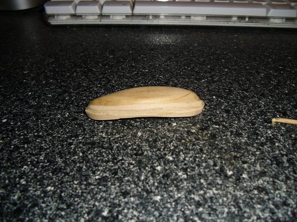
Joel, thanks for all of that useful information. I kind of got the idea of the 'thole pin' and 'wash strake' without actually knowing what they were called, but now I can look up picture reference much more easily! Plus, I was planning on just gluing the dowel onto the surface of the cap rail rather than drilling a hole; obviously a hole is the way to go. I was (and probably still am) going to use the tip of a toothpick for what I now know is called a 'thole pin', and I'll use some of the 0.020" plank for the 'wash strake'. And I agree: Chuck is good. The fault definitely lies with my extreme degree of ignorance and inexperience. It's a little too late for me to thin the hull more that I already have, now that I've done all of that internal work, but I think you are probably right that I should have made it thinner than I did. I was afraid that I was going to cut all the way through. I can live with it the way it is, I think, and I've learned something along the way. As far as the thickness of the cap rail, I cut it from the sheet, and just tried to dry fit it to the to of the boat. I heard that dreaded little snapping sound; I didn't see anything at first, but indeed, there was a crack through the tight curve of the stern. It was a clean break, and easily glued, but it made me think that I'd be better off thinning it down to half thickness before trying to fit it. I did sand it down to about 1/32", and now it's a lot more flexible, and bends easily to the shape it needs to be. But, before I do that, I'm going to try to put the 3 or 4 clinker-style planks on the hull. The trickiness of that, as I see it, is that I have to put the bottom one one first, and then put the next one (overlapping it), followed by the next. So I have to try to plan the position of the first plank such that the last one comes right up to the exact top, right below where I will then put the cap rail. It'll just take some measuring and planning, but I think I can do it. (I hope the degree of overlap can be somewhat variable to hide small degrees of imperfection, but we'll see.) I plan to use the 0.020" plank, cut to half width, and sanded to a slightly thinner thickness. I hope to have some pictures by late tonight...
-
Al, maybe I don't have a very discerning eye about these things, but that model looks great to me! I find it mildly humorous that you're asking me for advice, when I have this half-finished 2 inch long boat, and you have a completed full size ship with all the deck furniture and rigging and stuff that I don't even know what it is! But I think it will be a lot of fun to work on the mayflower together. Message me if you start a build log on it, please?
-
I'm interested to hear what the more experienced people have to say, but if it were me, I'd probably plank the whole thing, and then glue stuff on top. That being said, the placement of the deck structures may well affect on how you plank the deck. For example, you may be planning for a certain plank pattern, but if there are two deck structures kind of close together, it seems that the right thing to do is to use whole planks between them (even if that disrupts the plank pattern.) So, if you want to take that detail into consideration, it may well make sense to put down the structures first, and plank around them. (I think that you need to use the scale of the model to figure out how long the longest planks can practically be first, and if the spacing between deck structures is less than that, you should use whole planks between them.)
-
I haven't received the replacement parts yet, but I expected it to take some time, and I figure that if they're willing to replace them for free, they can do it on their own schedule. I have enough to keep me busy with the ship's boat for now. As far as a stand, I haven't worried too much about it yet. I expect I'll have to make a display stand eventually. (I'll probably just get a flat piece of wood, router a nice contour onto the edges, and use the model shipways pedestals to hold up the ship. http://www.modelexpo-online.com/search.asp?SKW=cat1_MX Pedestal I don't think it's critical to have a real wooden stand during the build. I've seen people use pillows, foam blocks, keel jigs, and a host of other things to keep the ship upright during construction. I do have a pretty good sized piece of foam that I think I'll use for as long as it works. I can even cut a contour into it to hold the bottom of the ship more securely if it comes to it. PS. I guess the April Fool's joke is that today is only March 31st!
-
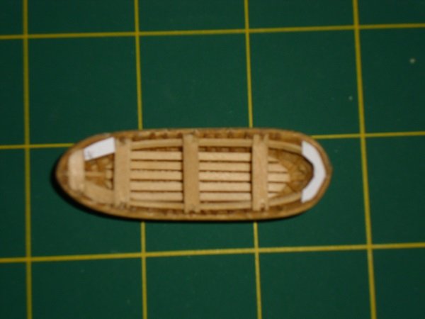
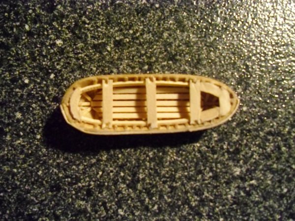
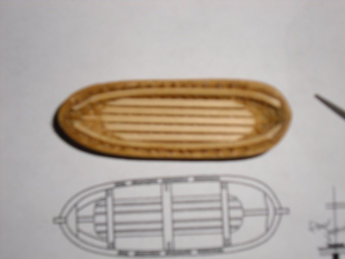
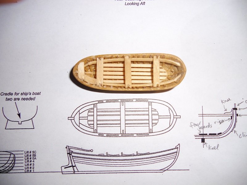
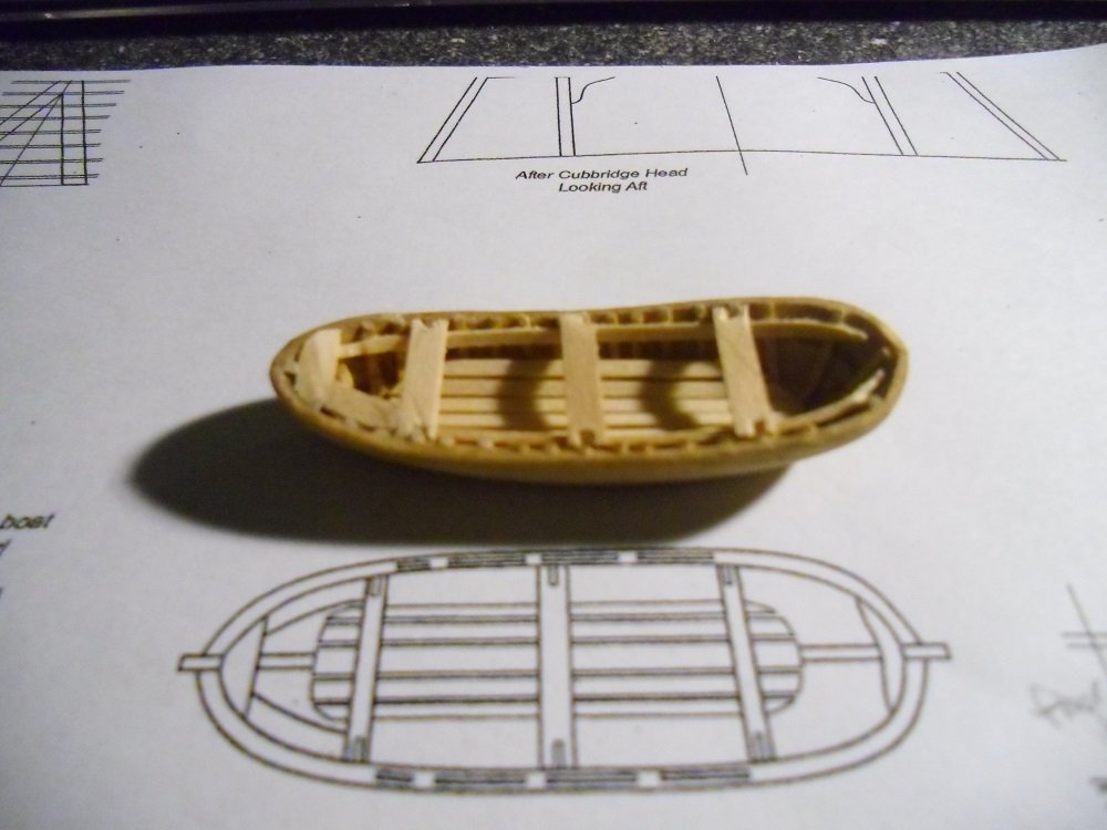
I decided to stain the risers natural and the thwarts golden oak, again, for some contrast. I have a picture of the floorboards installed, then one with the risers (sorry it's out of focus, my camera isn't good at close up shots.) Then I have a couple of views of most, but not all, of the thwarts installed. As per the instructions, I used 1/16" x 1/32" for the floor boards and the risers. They called for 1/8" x 1/32" for the thwarts, but as there was no corresponding supplied strips of that dimension, I used some of the 0.020" x 1/8" strips (that I think are meant to be used for the second layer of hull planking.) My caliper measured those to be about 0.03" thick anyhow, which is pretty much what was called for. I went to the trouble to put little notched in the thwarts to accept the frames, but all of that will be covered by the cap rail shortly, so it was just a little practice in microsurgery...
-
Sounds like a pretty good deal, Al. For my purposes, I'd just go to Michaels (because there's one right near me) and they sell 11 blades for something like 50 cents each in packs of 5 or 15 or thereabouts. The trick is to print out the 40% off coupon from their website before you go (or get it up on your smart phone if you have one). That takes it down to as good a deal as micromark, and you don't have to wait for it to be shipped out to you. I like the instant gratification of walking out of the store with it. here's a sample link to the michaels coupon page: http://www.michaels.com/on/demandware.store/Sites-MichaelsUS-Site/default/Coupons-ViewCoupons
-
Al, I'm certainly not the best person to ask general questions, as I'm pretty new to the field. But, that being said, I'll give you my experience: I use an 11 blade (not because it's necessarily the best, but because I have them handy.) I think the trick is to make sure the sheet is on a nice flat surface, and don't try to cut through in one pass. Just make a light pass over the tab, and then repeat, with gentle pressure until it cuts through. You definitely don't want to try to pop out the piece until the tabs are cut, because it'll probably break somewhere other than the place that you want it to. I sometimes make 5 or 7 passes with the 11 blade until it gets through. Also, it's probably a good idea to err on the side of leaving some tab on the piece, and sand it off later (rather than leaving some piece on the tab, if you take my meaning.) And, yes, a sharp blade is a good idea. That being said, I've been using the same blade for quite a while now, and it still seems to get the job done.
-
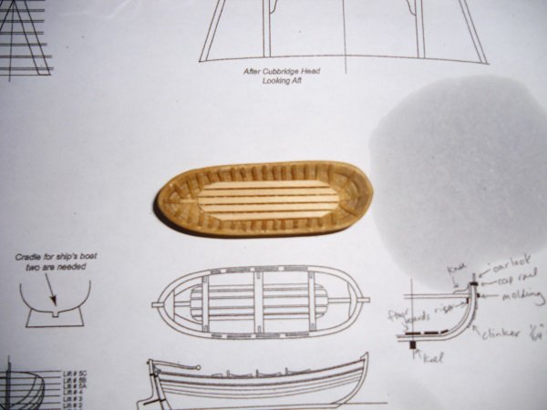
It looks like the oar locks that are in the plans and in the photo in the instruction manual are made of wood. It's tough to be sure, but it looks like a small dowel on one side, and a thin (maybe about 1/64" thick) sheet of basswood on the other. You can see it from above and the side in the plans, and it's in the photo in the book. And, yes, I work in medicine, so I can sometimes co-opt some of the medical supplies for personal use. It's ok; I own the office, so it's only stealing from myself...
-
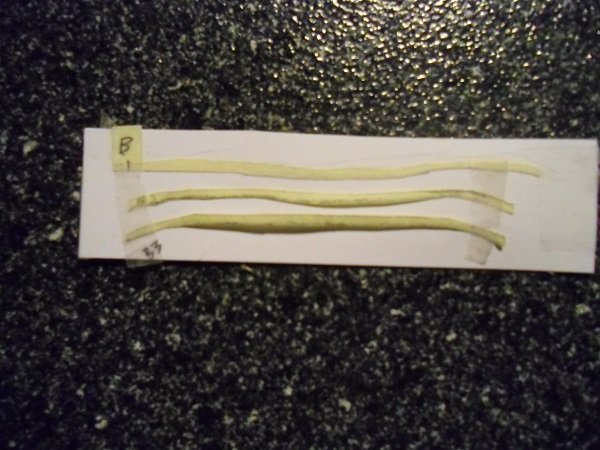
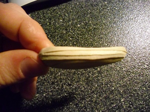
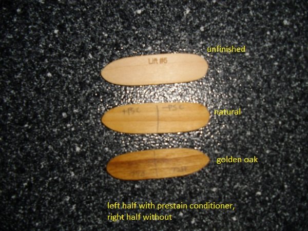
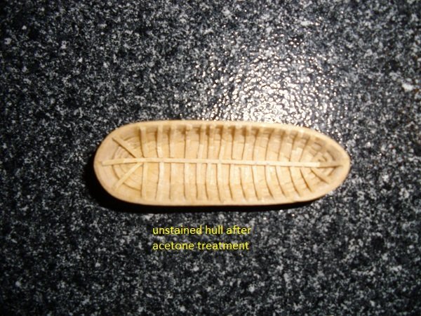
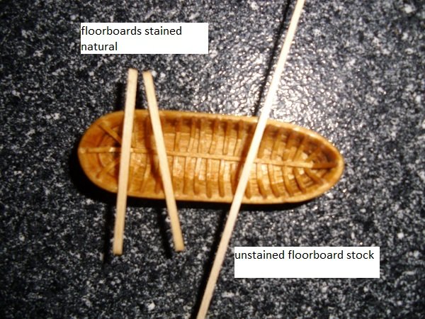
I did try natural and golden oak on some scrap, (each with and without prestain conditioner) and I present the findings below. My take is that the natural does something, but it's pretty subtle. (Correction: the middle piece has conditioner on the left, the bottom piece has it on the right. I put it upside down for the picture!) The conditioner didn't seem to make any appreciable difference on that particular piece, but I assume that dependent on the type of wood and the state of the wood. I didn't think that the golden oak was too dark to use straight, so I used it on the hull. I used the natural on the floor boards. In the unfinished hull photo, you can see that I managed to get rid of pretty much all of the white residue from the CA glue. It was actually pretty easy to do: I just drew some nail polish remover (acetone) into a 1 cc syringe, and put a 30G needle on it, and put tiny microdrops wherever the white stuff was, waited a few seconds, and wiped it off with a cotton swab. I did that a few times, but the first pass did pretty much the whole job. I finished the hull with prestain conditioner and straight golden oak. I hate opening and closing those metal cans, so I got some 4 oz mason jars and poured a few ounce of each of the prestain conditioner, natural stain, and golden oak stain in 3 jars. (I wonder if the rubber gasket is ok with the mineral spirits, but so far, it seems to be holding.) Then, I just dipped the whole hull and each floor board into the prestain conditioner, and let them sit for 15 minutes, and wiped them off. Then I also just dipped the whole piece into either golden oak or natural as appropriate. I only left the oak for about 3 or 4 minutes, but I left the natural for the full 15. The two short pieces are the stained floorboards, and the longer piece is untreated. I don't see much difference. But I think the hull looks great with that color. Next step is to actually install the floorboards...
-
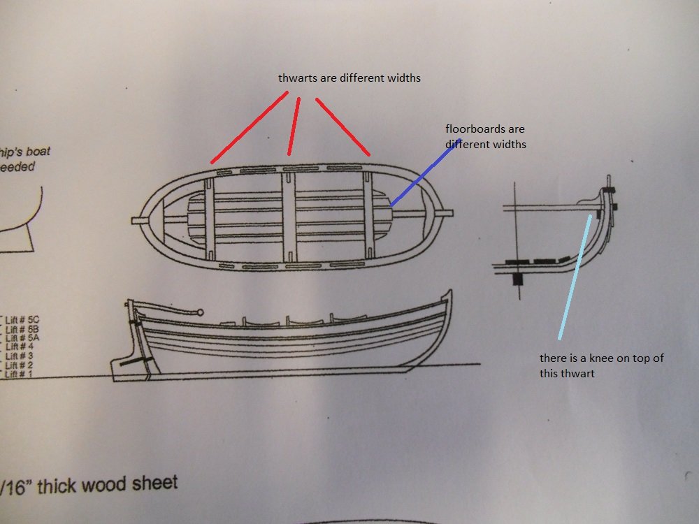
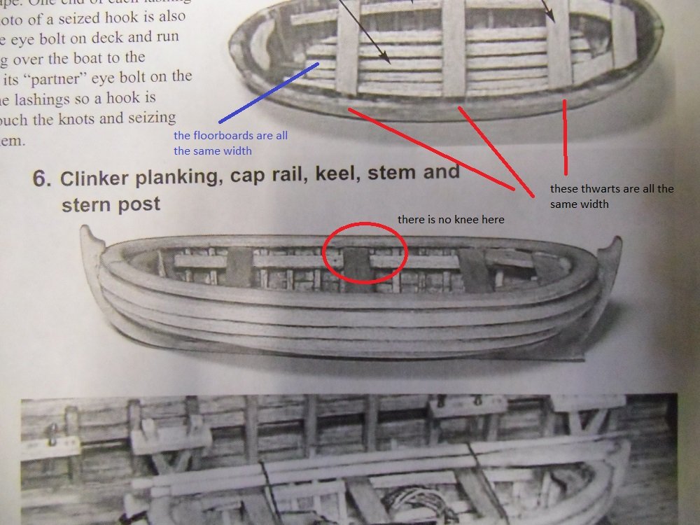
Al, I think there's room for both schools of thought: the pristine shiny new model and the weathered look. My personal taste is more to the newer look. But one point I'd make is that if you go for the weathered look, it shouldn't be because you can't do the other. It should be because you can do it very well, and make an artistic choice to deviate from it. Since I'm new to this whole game, I'm going to try to develop the skill to make a clean model, and then in the future, I might challenge myself further to do weathering. But, while we're at it, I think I get the idea of the floorboards, risers, and thwarts, although the plans seem to be a bit different from the instruction book and the photos therein. I know that there's not one 'right' way to do this, but I'm tempted to go with the book and photos, (cuz they were really built, whereas the plans are more theoretical). There are a few pieces that don't actually seem to be in the kit; the oar locks and an unnamed piece that I would call a 'knee' (actually, 6 knees). I guess if I want to use those, I'll have to fashion them from scratch. (I'm probably going to eventually want some advice on how to tackle that stuff.)

-
these images (from the web) seem to fit more with what I would get if I just glued the floor boards right onto the frames. So, yeah, Steve, I think you've got it right, and I'm going to do it just as you say. But first, I'm going to stain the inside of the boat. I did a few practice stains on scrap wood with natural and golden oak. I think the golden oak isn't too dark, and the natural is hardly different from the unfinished wood. So my plan is to use golden oak on the inside of the boat, and natural on the floorboards, thwarts, risers, etc. so they'll stand out. (But, yeah, I'm definitely using wood glue...)
-
well, I put some acetone on the white spots (which was most of the inside of the hull, and wiped it with a cotton swab, and the white pretty much disappeared. It was like magic. And all the frame pieces stayed well attached, too. But, I'm going to be much more careful in the future. Question: as far as putting in the floor boards, I can't tell if they're supposed to be flat all the way across the five boards, or if they are meant to follow the contour of the bottom of the hull. I just cut the pieces roughly, and laid them in the bottom, and they definitely won't lie flat unless I somehow elevate the center one off of the bottom to be on a higher lever where the most lateral ones will want to lie. a quick google image search looks like most of them have the floor boards pretty flat on a level like this one; I guess I could put a shim under the center board, but I wonder if it's worth it.
-
thanks, tigersteve, I'm glad you suggested gluing before sanding, because it would never have occurred to me. I'll sleep on that, as I have some other things to do first. (There's some floorboards, risers, and thwarts that need to go on first.) This ship's boat is a whole little model unto itself. It sounds like the best way to remove CA glue is to not use it in the first place. Then comes sanding and a distant third place is using a solvent or debonder. I'm in such a tight space there that I don't really think I can sand (it's about 2-3 mm between each of those frames. I may try folding a piece of sandpaper and getting it in there. If I can't bear that, I might try dropping acetone with a 30G needle in there and wiping it off with a cotton swab. The good news is that the floor boards will pretty much cover most of that CA glue residue, and I've learnt my lesson for the future. If you can avoid CA glue, don't use it. If you need it, then really use the absolute minimum.
-
Sounds great! The only thing I might suggest is to start call him "Chuck Passaro" instead of "Chuck Pissaro". (I'm not sure he'd like that as a nickname...) But other than that, I think we're ready to roll!
