Check out our new MSW Sponsor Innocraftsman
×


TUEL
-
Posts
55 -
Joined
-
Last visited
Content Type
Profiles
Forums
Gallery
Events
Everything posted by TUEL
-
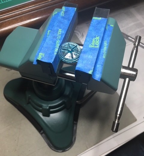
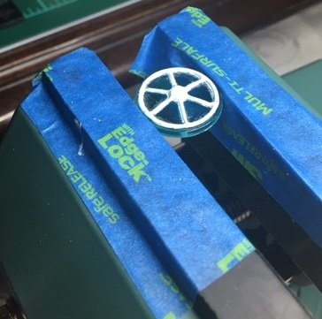
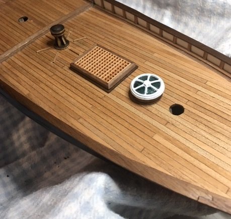
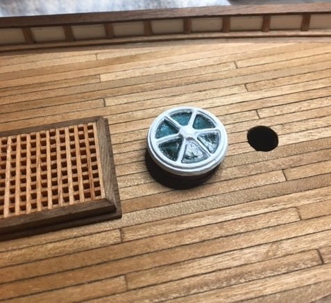
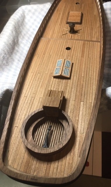
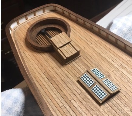
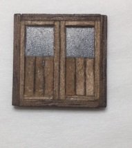
I clamped the plastic fore skylight in my vise to get it to a good working height, and proceeded to paint it. This is the skylight after several coats of paint, and tung oil applied to the base. The quality of the molded plastic skylight is just so poor, and its even more apparent with paint applied. The seals between the panes are very uneven which made it very difficult to paint. Here is the fore skylight glued to the deck.
-
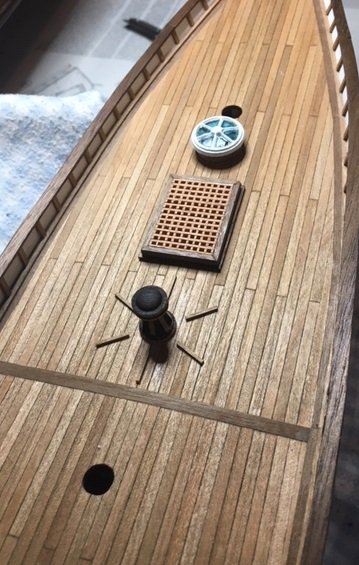
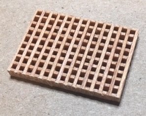
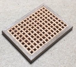
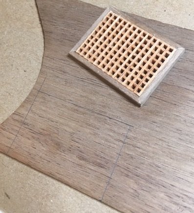
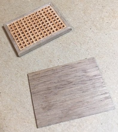
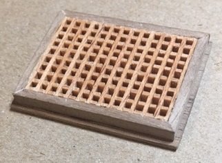
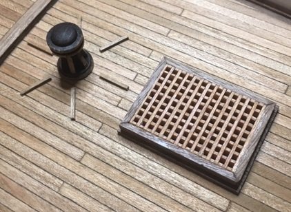
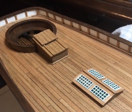
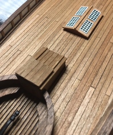
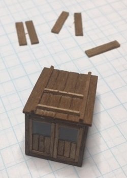
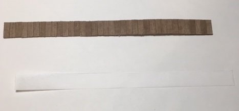
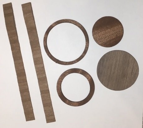
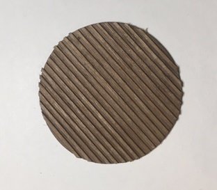
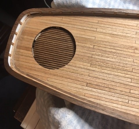
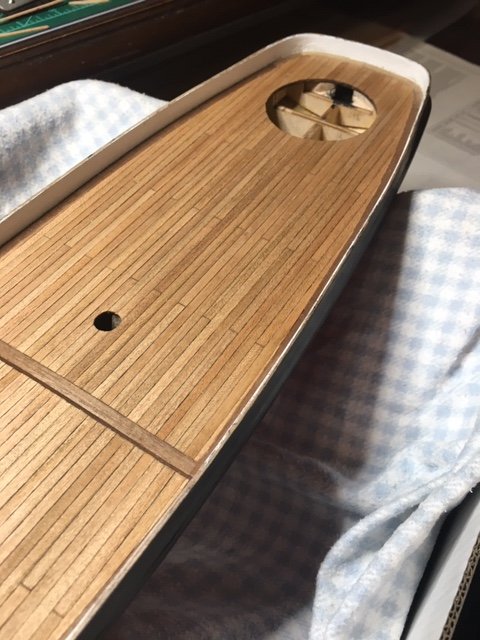
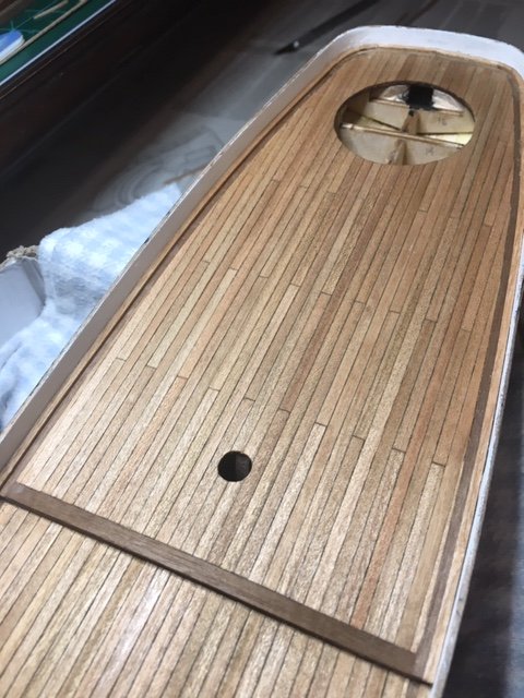
My progress has been slow over the past couple of weeks. Other things have encroached upon my build time, but I have been able to do a little work on it the past few days. I began building the grating for the main hatch assembly. I failed to look at the drawings to notice the dimension of the grating, and assembled all pieces provided with the kit. I then went to the other build logs to review photos and noticed that a couple of the other hatches were not the same dimensions as mine. I then went back to the plans and measured the grating, which per the drawings is 21mm x 31mm. I cut the grating to be as close to these dimensions as I could (20mm x 30mm). Next, I mitered 2mm x 3mm walnut strips and used those to trim out the grating. From a 0.5mm walnut sheet, I cut a piece that was 1mm wider and 1mm longer than the grating assembly, then glued the grating to it. I applied a coat of tung oil to it. I set this aside until I could complete the toe boards on the deck around the capstan (I’m not exactly sure that toe board is the correct term, but I didn’t want to take the time to research it). Per the kit drawings there are 6 of these strips, which would mean they are 60 deg apart from one another. I will glue 2 to the deck along the center on the deck. My approach was to make a template out of cardboard, starting with a section cut to 60 deg. I trimmed the piece and slotted each side so that I could lay each strip exactly where it needed to be. I used this template to set the other 4 strips. Here is a sequence of photos. Next, I glued the main hatch assembly My next task is to paint the fore skylight.
-
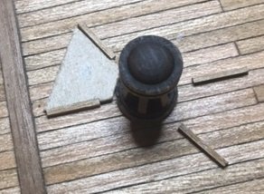
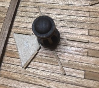
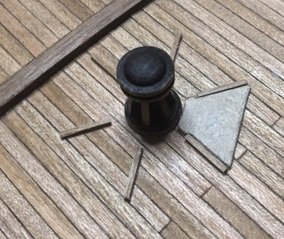
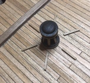
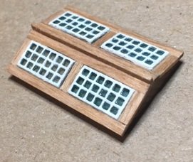
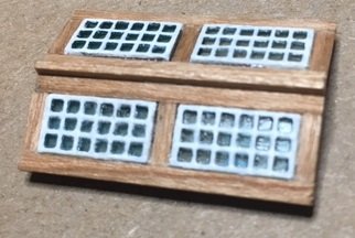
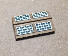
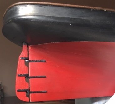
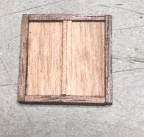
I was not very satisfied with the first skylight assembly. I used the 1mm x 2mm walnut strips provided in the kit to trim around the skylights. The quality of these strips was extremely poor. There was a lot of splintering on one or both edges of each strip, and it appeared to not be uniform in width. I tried to be particular as to which strip I used, but did find ant that were completely satisfactory. It seemed to also very in thickness along the length of the strips. I have some 1mm x 2mm cherry strips that I used on the side railing that is excellent quality. I wanted to use the walnut strips because of the darker color, but decided I would rebuild it with the cherry strips. The last picture is the one built out of walnut; the picture below is the new one built with the cherry strips. It is lighter in color, but much tighter in the fitting of the strips. Here it is installed on the deck. I followed this with building the capstan. I’m not sure what type of wood was used for the capstan, but it’s very light colored. Maybe it was box wood or poplar. The vertical pieces that are glued into it are walnut I believe, so I was somewhat concerned as to how it would take the stain. I decided to glue those pieces in first, then stain it. I used a MinWax stain named Honey. It looked to be a somewhat medium brown in the charts I looked at. When I applied the stain, I was not very please with how it turned out. It is definitely much darker than I thought it would be. But, there is no correcting it now. Here is how it looks: Now its on to building the grating assembly.
-
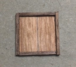
Thanks SandyBay! I built the skylight assembly per the details in the plan using 1mmx2mm walnut strips for the framing. I am not pleased with the alignment but here is the assembly. In hindsight, I should have used a larger 1mm sheet and cut holes for the skylights. That would have a much better appearance. The glue needs to cure over night and then I will sand and trim to try to improve the appearance. Here it is sitting on the deck (not glued). I will post additional pictures after I've had some time to trim and adjust the assembly.
-
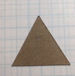
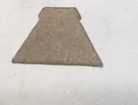
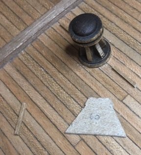
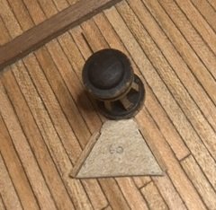
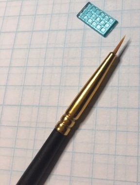
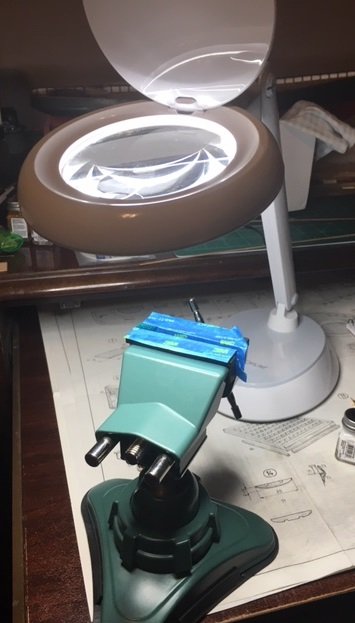
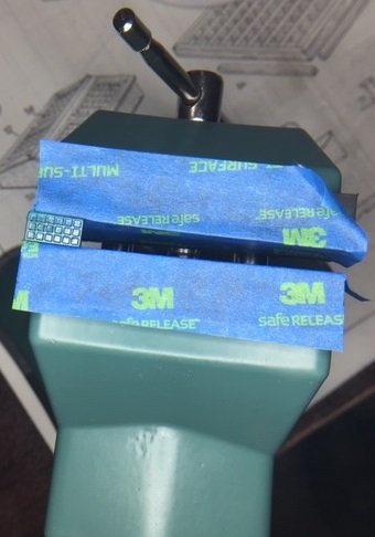
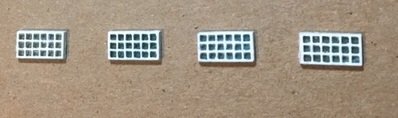
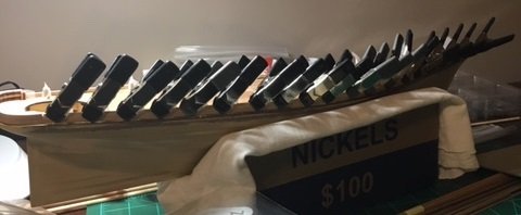
I have made some progress on the skylight group. My first impression of the plastic skylights was that it would be extremely difficult to paint the seals between each pane. Hamilton commented that he used a straight pin and a hand-held magnifying glass to paint the seals white. I was most impressed with the quality of his work on that. I thought about trying to build the skylights out of wood and plastic, but considering the small scale it just didn’t seem feasible. I turned my attention to painting the skylights. I did a little research on some of the fine scale plastic model websites. One thing that is similar to this application are canopies on airplanes, particularly WWII era planes. These canopies have frames molded into the clear plastic that have to be painted to look like metal. Very often I saw a reference to a special masking tape that the modelers use – Tamiya masking tape. It is a very thin plastic tape that can be bought is various widths down to 2mm. I purchased a roll of this tape thinking I could apply it to the skylights, then cut out the window pane portions. What I found was that the window panes were just too small for there to be much area for the tape to stick, and when I tried to trim it is just didn’t work. I abandoned that and turned my attention back to painting the seals. I made a trip to my local Hobby Lobby to buy some Testors flat white paint. While there I found and purchased a package of 10 fine paint brushes for detail work. One of those brushes is very small and supper sharp tipped. Here is a picture of the brush beside one of the skylight pieces. The grid on the graph paper is ¼ “, so you can see how fine the tip is in comparison. I used a vice to hold the skylight at a good working height, and have an LED lamp with a built-in magnifying glass. I lined the jaws of the vice with painters tape. Here is the view through the magnifying glass. I found that once I began painting that it wasn’t as difficult as I thought it would be. Here are the finished skylight pieces.
-
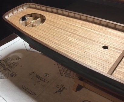
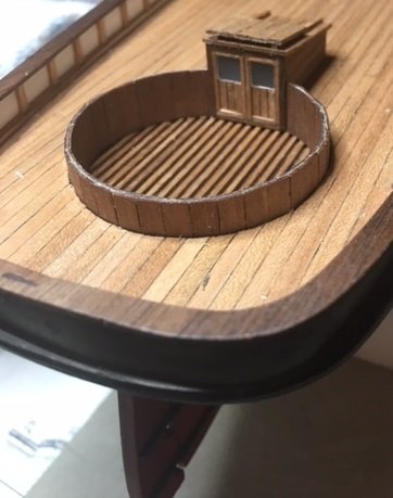
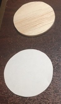
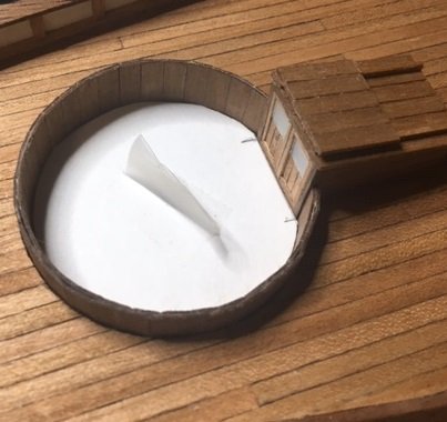
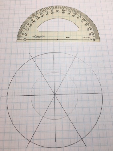
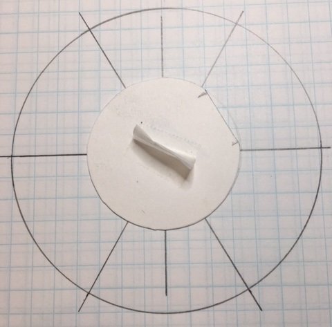
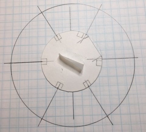
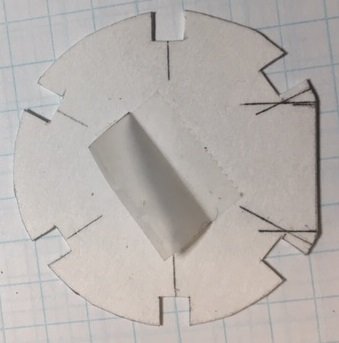
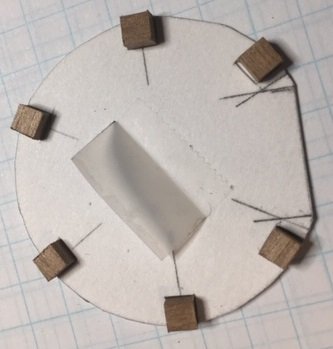
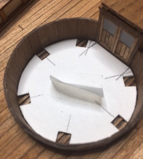
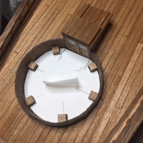
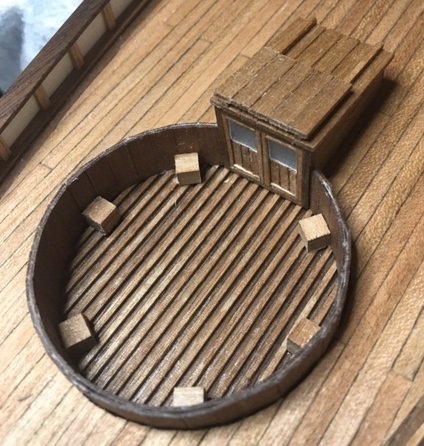
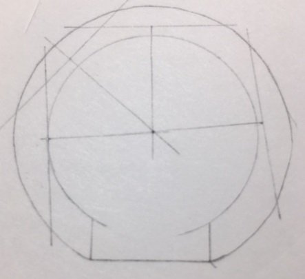
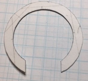
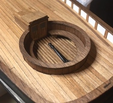
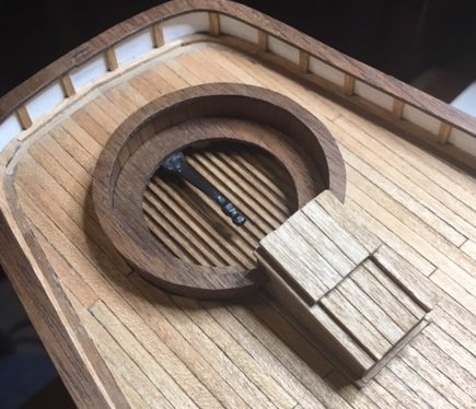
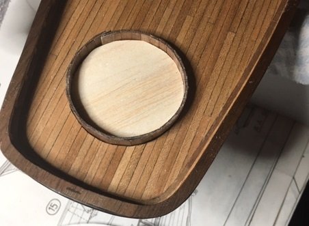
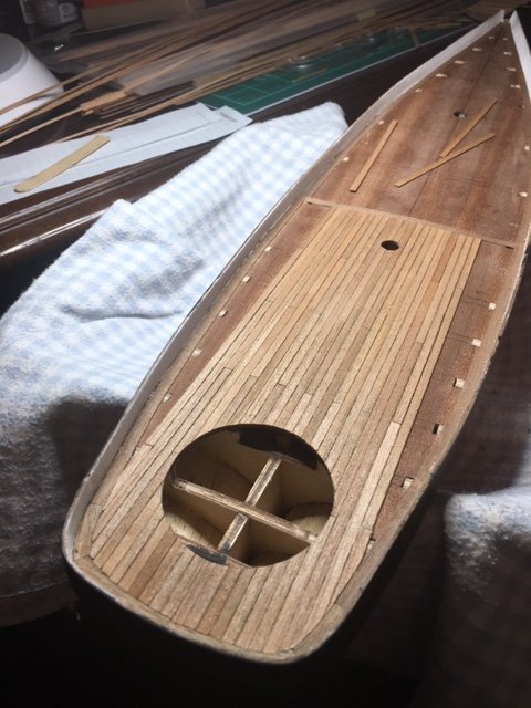
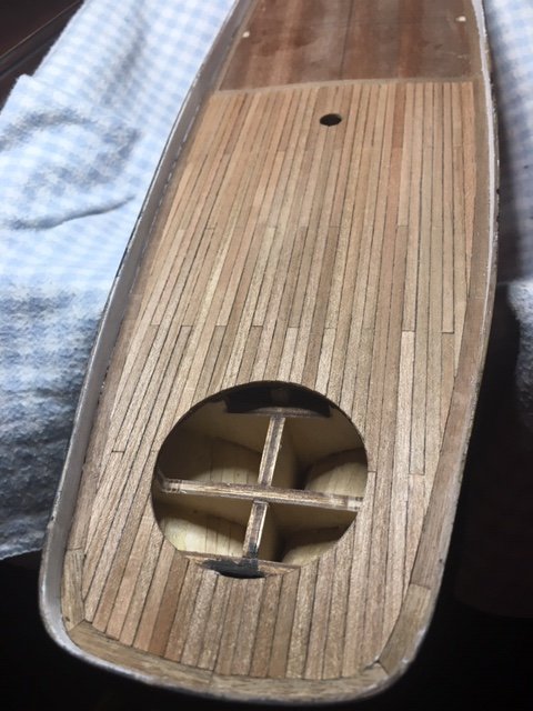
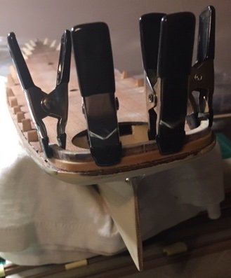
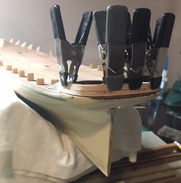
I glued in the completed companionway, and then the cockpit wall. I used the balsa insert to make a pattern out of some heavy paper stock that was the size of the inside diameter of the cockpit. I trimmed the edge so that it fit to the companionway doorway. I folded and attached some scotch tape so that I could more easily insert and remove the pattern. I also made a couple of duplicate patterns in the same heavy stock paper for use later. I have a small protractor that I used to make a circle on graph paper, and divided it into 60-degree segments. I then drew diagonal line between each 60-degree point through the center of the circle. This identifies for me where each of the 4x4 mm supports for the cockpit bench will be located. Laying the pattern on this circle allowed me to mark the location of each seat support. The companionway is in the upper right area of the pattern as you can see in the photo. I moved the two bench supports beside the companionway over 2 mm so that the bench aligns correctly. This is the pattern with each slot cut out. Here is the pattern inside the cockpit. Here are the bench supports glued in, followed by the pattern removed. I used one of the extra paper patterns to make a pattern for the bench top. The pattern measures to be 45 mm in diameter. Per the kit drawings, the bench top is 5 mm wide. Using a little geometry, I located the center of the pattern. Then I used a compass to draw the interior circle, then cut it out as a pattern for the bench top. I used this pattern to mark the edges on a sheet of 0.5mm walnut. The top hand rail of the cockpit measures to be 3mm wide on the kit plans. I allowed for the interior to overhang the inside of the cockpit by 0.5 mm, so I drew one circle on the walnut sheet to have a 44mm diameter. On the same center, I then drew a 47mm circle, then cut both out with my band saw. After a little sanding, this is how each turned out. Next I applied one coat of tung oil. I cut a small piece of plywood, and sanded it to fit the head of the tiller-bar. I used 5-minute epoxy to attached the tiller-bar to the wood piece. This gave me a solid base to glue wood-to-wood in mounting the tiller bar. I painted it black, but I failed to make any pictures of the mounted tiller-bar before I covered it up with the bench top. I glued the bench top and top rail. Here are several pictures of the finished cockpit.
-
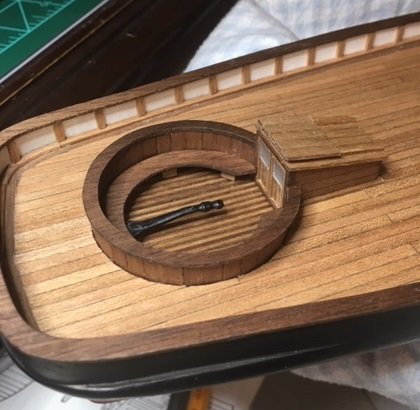
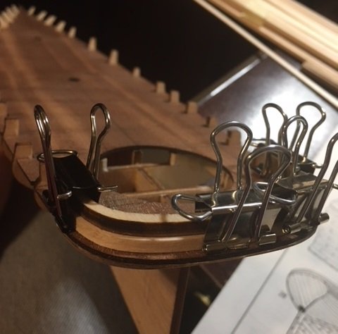
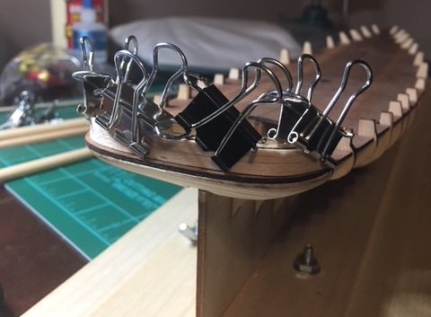
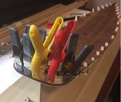
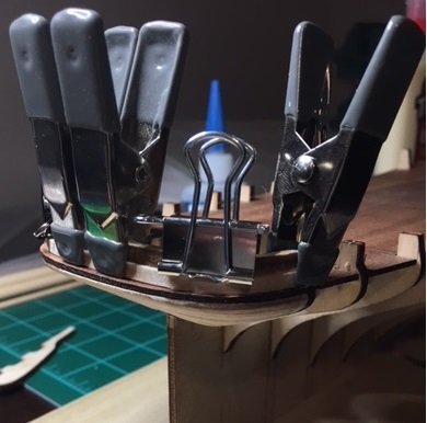
I’ve been traveling on business, and its spring time in Alabama, so I’ve not had much to work on my America. I’ve made a little progress over the last day or so. The rudder is now attached. Next, I refocused on the cockpit. I glued the two strips of walnut pieces together, then inserted it into the cockpit opening. I had some scrap balsa that I used to make an insert to place pressure on the wall while it dries to form. I’m going to let this dry until tomorrow so no more work for this evening. Hopefully, I can spend some time on it over the next several days.
-
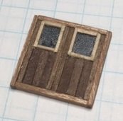
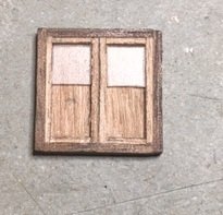
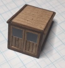
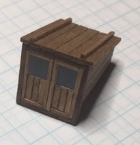
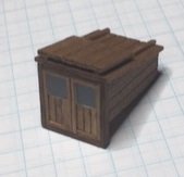
Since the last time I posted, my build time has been limited for various reasons. I began construction of the companion way. I decided not to use the windows supplied with kit for the doors. It just seemed that trying to paint the detail needed around the window framing was going to be beyond my skill set. I keep my eyes open for pieces of wood, plastic, and metal that I think I can re-purpose and use in some way. I can’t remember where I found these, but I have some thin plastic pieces that I thought would be perfect for the windows. This plastic is less than 0.5 mm think, and one side has a texture to it giving it somewhat of a frosted appearance. I thought this would work well for the window panes. I completed an assembly of the companion way doors with pieces cut from the plastic as windows. I used cherry strips for the outside framing, and walnut for most of the interior pieces. I had the idea of cutting very thin strips (< 0.5 mm) from basswood, and gluing these around the edge of the windows, thinking the lighter colored wood would have the appearance of a painted edge around the window. I was not satisfied with the resulting assembly. Here it is in the next photo, but as I said, I'm not going to use it and will make another one instead. I think the darker colored wood on the inside versus the lighter colored wood on the outside was not a good combination. On the second try I decided to use walnut for the outside framing and cherry for the inside strips. Also, I did not like the basswood strips around the windows, and decided that I would make the windows somewhat larger. I started with a 16mm x 16.5 mm cherry piece for the backing, and 1mm x 2mm walnut pieces for the outside framing. I used cherry for the center frame pieces. I cut the window panes from the plastic in the earlier photo to fit the opening at a height of 6mm. I removed the plastic pieces and painted the back piece black, then reinserted the panes. Then I added cherry strips to the lower portion of each door. Finally, I applied a coat of tung oil. Here is the finished assembly. I considered trying to find something that would simulate door handles or knobs, but at this point I feel I’ve spent more time on this piece than I need to and should move on. I glued the door assembly onto the companion way piece, and then began building up the roof. I have now turned my attention to attaching the rudder so that I can mount the tiller bar. After that I will complete the cockpit build (walls, caps rail and bench).
-
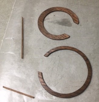
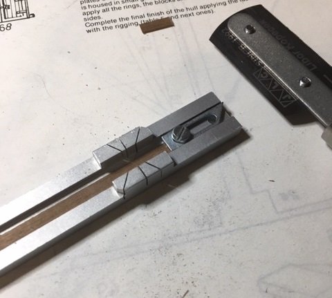
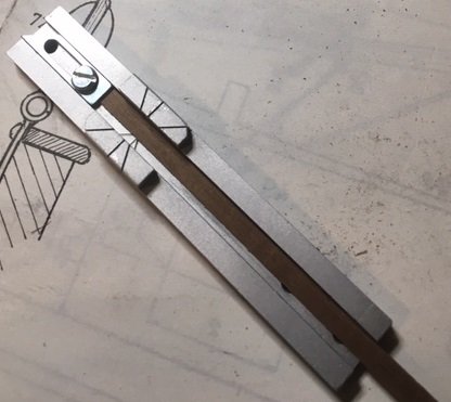
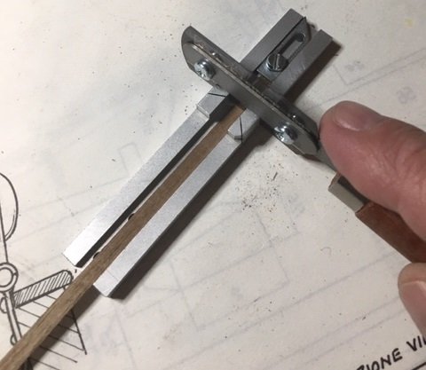
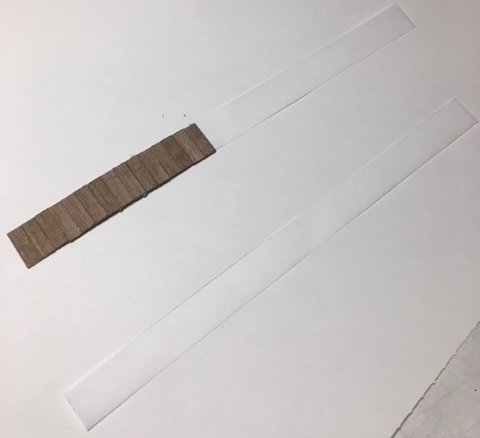
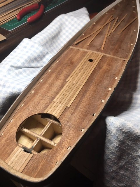
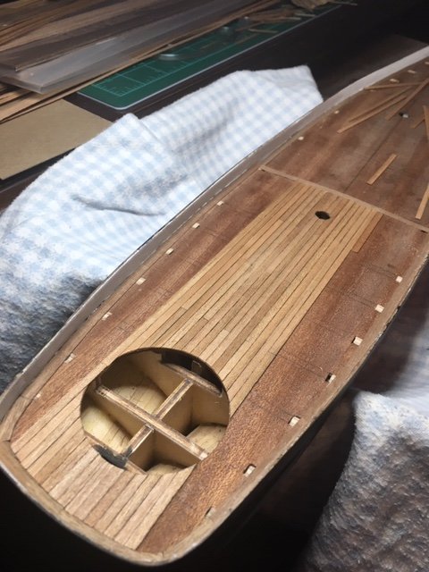
My focus now is on construction the cockpit and the companionway. I re-read several of the build logs to see how others have completed it, and focused on this portion of the plans. I had not opened the hardware package until now. As I looked at the quality of the various hardware pieces, I have to say once again I’m underwhelmed. I expected to have molded pieces of the companion way doors, but am disappointed to see that these doors are not supplied, only the small windows. I do not understand why Mamoli supplies a molded door piece for the forward companionway, but not for the rear companionway. That makes no sense to me. As I’ve looked at the small scale, and the intricacy that will be required to paint the window seals and the seals around the sky lights, I’ve started looking for alternatives. Hamilton described in his build log how he used a straight pen as a make-shift brush under a magnifying glass to paint the seals around the glass pieces. I still may do that also, but my plan now is to find plastic that can substitute for the windows, and frame around it with 0.5mm strips of a lighter colored wood. If it looks like I think, I will not have to paint anything around the windows. From Greatgalleons build log, it appears that he built the cockpit and the companionway as a complete and separate unit and then installed it in the deck opening. I think I will take a different approach and build it piece mill into the deck, so from here I am proceeding with the cockpit floor and walls. One really good purchase I’ve made and used extensively is a JLC saw and miter box. It has tight precision and makes excellent cuts. I used this to cut the 11mm pieces which will be used for the walls of the cockpit. As can be seen, it has a stop that is set with a screw. I set it so that each cut was 11 mm in length. I used walnut strips for the cockpit wall. I took a strip of heavy stock paper and set it against the edge of the deck opening to determine the circumference. I found it to be 147mm. I cut two strips of tracing paper to11mm x 147mm, and began gluing the walnut strips to it. Hamilton mentioned in his build log that the laser cut pieces for the cockpit floor, seat and wall cap were not correct and I can see that he is correct. Using a caliper, I measured the opening and using my bandsaw cut a floor piece from the walnut sheet I used for the cap rail. In this picture you can see the differences in the dimensions. Also, the laser cut pieces are cut out of mahogany plywood, which is really nice looking wood. But, I just don’t think the mahogany blends well with the walnut and cherry already on the deck. Therefore, I have decided to use primarily walnut for the cockpit and companionway pieces. I don’t much think I’ll have a use for the mahogany pieces. Using the 1mm x 1mm walnut strips from the kit, I lined the cockpit floor. Here is the result. I applied 2 coats of tung oil to the floor and to the cockpit walls. I also think I will build the cockpit in the deck as opposed to building it separate and installing it as one unit. Here is the cockpit floor installed in the deck opening.
-
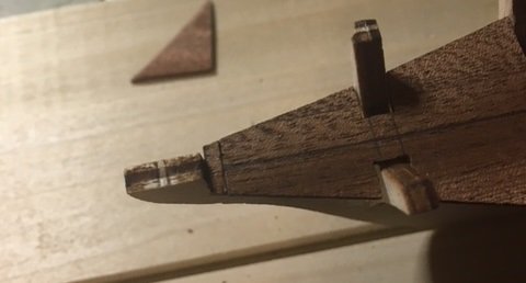
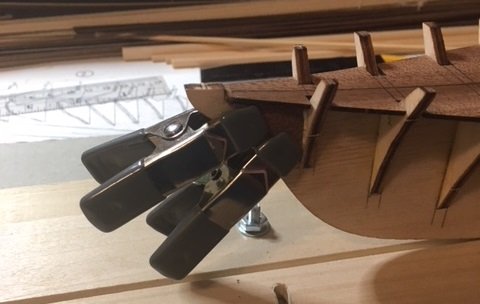
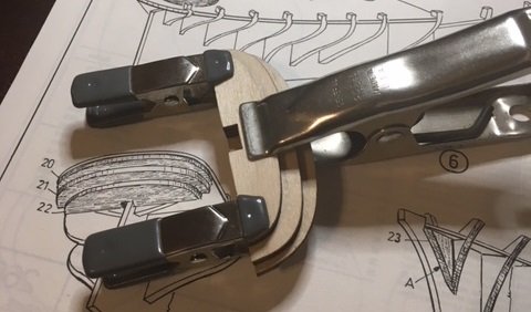
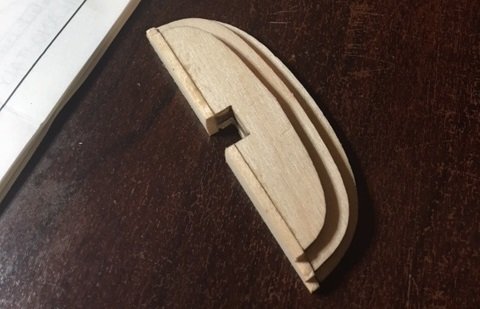
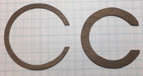
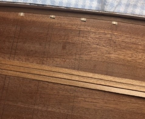
Below is one of the cap rail pieces after cutting on the bandsaw and some sanding on the edge. This piece still has the pattern stuck to it. Here are all 3 pieces cut, sanded and the pattern removed. Next I will apply tung oil, then attach them to the hull.
-
Now I'm cooking with gas... I cut the cap rail pieces this afternoon. What a pleasure this bandsaw is to use and what a difference it made.. I'm sanding and finishing the cap rail pieces and will post some pics when I'm through with that step. Thanks for the comment Gary, and you're welcome. My pattern method worked real well with this bandsaw (no splintering at, very precise).
-
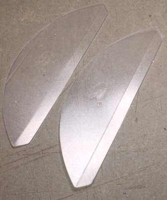
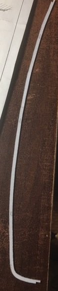
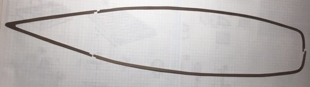
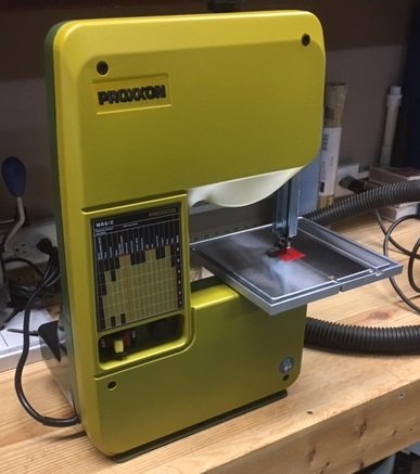
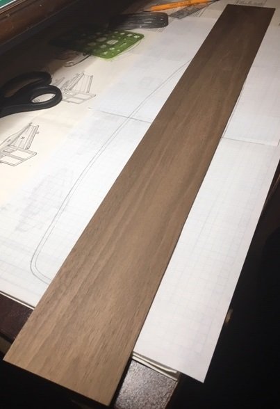
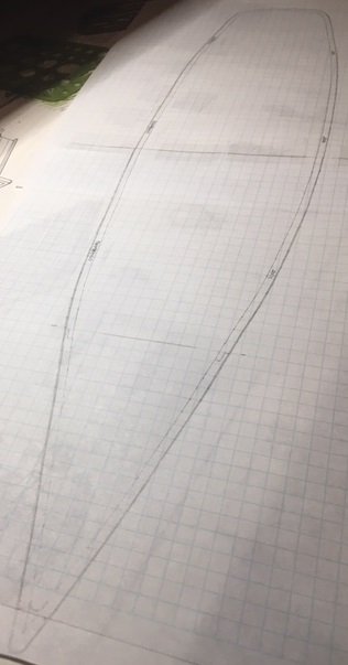
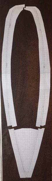
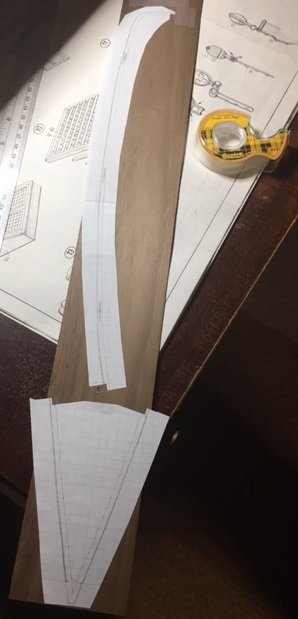
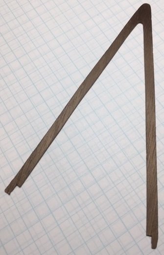
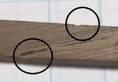
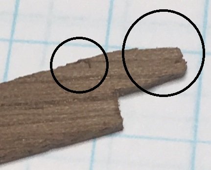
I continued with the vertical pieces around the remainder of the deck. For the cap rail, I purchased a walnut sheet (3/64” x 3” x 24”) from Model Shipways. I bought 2 in case I need a spare. 3/64” is 1.19mm, which is slightly thicker than what the plans called for (1mm). I turned the hull over and traced the outer edge onto graph paper. This required two sheets. I marked the hull on both sides with painters tape at the step between the fore and aft decks. The painters tape allowed me to line up the two sheets. I traced the fore deck on one sheet, then the aft deck on another, trimmed one of the sheets, and then taped them together. I measured 3.5mm inside the edge along the entire deck and drew the inside edge line, then measured 0.5mm outward from the traced line and drew that line. This gave me a pattern 4mm wide that matched the exact contour of the deck with a 0.5mm overhang. I then cut the edges out, making 3 pieces: a V-shaped piece for the bow, and two pieces that run the length of the starboard and port sides that meet in the center of the stern. Next, I applied 3M two-sided tape to the back side of the V-shaped piece so that I could apply it to the walnut sheet. I intended to apply all 3 pieces, but realized I should cut one side, then apply the other side for ease of access on my bandsaw. Here is the walnut sheet ready to be cut. I applied 3M painters tape to the other side to help prevent the splintering. My bandsaw is a 12” bandsaw, obviously not designed for precision cuts on 1mm thick wood. I was concerned about the precision, so my plan was to cut it to within maybe 0.5mm to 1mm of the pattern, then sand the edge. Once completed, the pattern can just be peeled away and discarded. It sounds like a great plan, but didn’t work out that well. The thickness of my bandsaw blade versus the thinness to the walnut sheet just didn’t allow for the precision I wanted. Despite taping the backside and going very slowly, there was still splintering and I just was not pleased with the results. After cutting the V-shaped piece and sanding it, I stopped and decided I needed a plan B. Here are a couple of close ups with circles around some of the consequences of the splintering. As for my Plan B… I’ve ordered a Proxxon Micro Bandsaw. It’s supposed to be delivered day after tomorrow. I’ll recut the V-shaped piece. The other pieces haven’t been cut yet. Hopefully the quality improves with the new saw. The only difference between the men and the boys is the price of the toys...
-
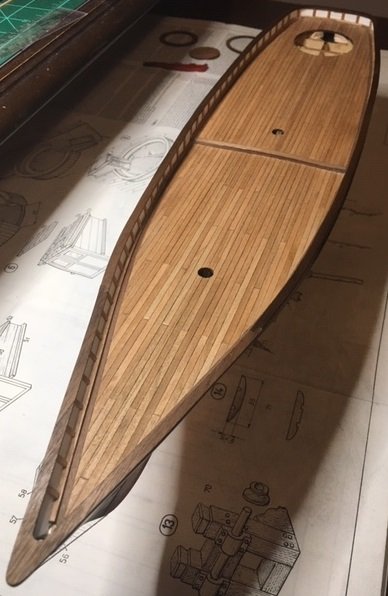
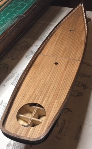
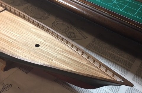
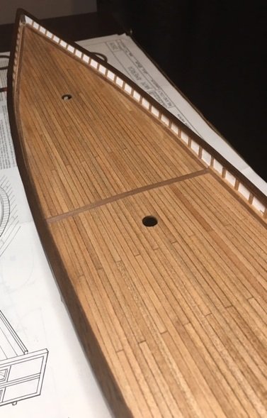
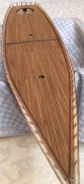
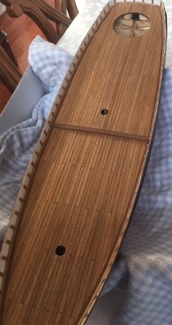
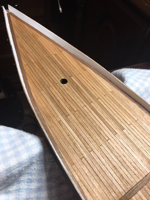
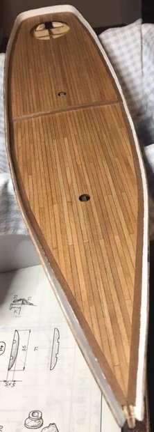
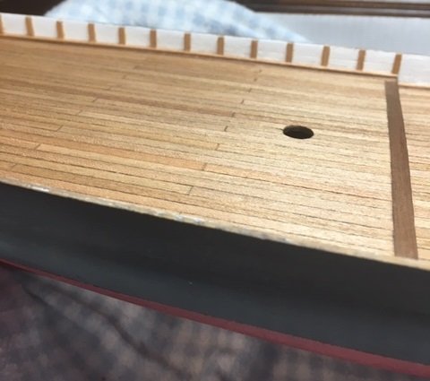
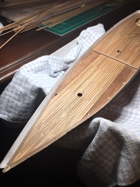
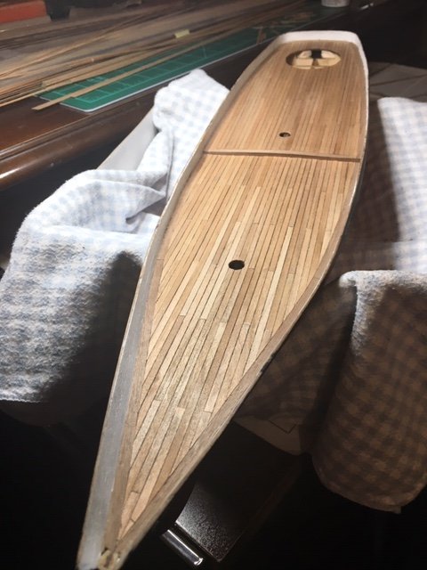
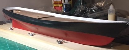
I sanded the deck and applied 3 coats of tung oil finish. I don't remember if I mentioned it, but I used walnut around the edges and between the decks, and cherry for the deck planking. I really like the colors and don't think these pictures do it justice. Next step was to follow the plans with vertical and horizontal strips around the edge of the deck. I'm continuing to add the vertical pieces around the inside of the deck over the next few evenings. I have some interruptions coming up over the weekend, so time will be limited until next week.
-
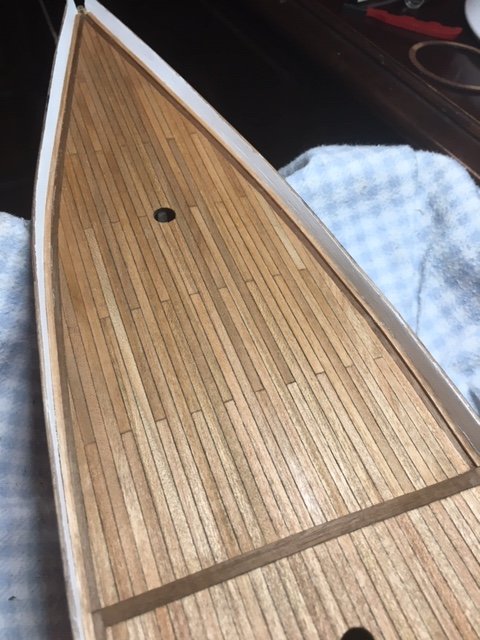
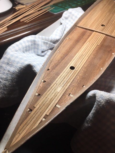
Thanks Gerty! I continued with the planking on the fore deck. Here is a progression of that work. Ready for sanding and then tung oil.
-
Hamilton: Thanks for posting! Yes, you are correct - it was probably not the best kit to pick as one's first kit. Besides the lack of precision, the poorly translated and very limited instructions are not what a first timer needs. Your Yacht America build log has been invaluable to me! I really appreciate the effort you made with the photos and the details. I can't tell you how many times I've been back to it, found certain pictures, zoomed in and noted details. Please keep an eye on my log and steer me in the right direction when needed! Thanks, Tim
-
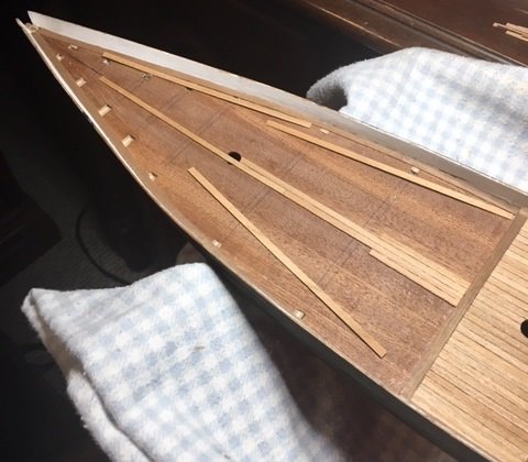
I have started and completed the aft decking. Here is a progression of that work Here is the aft deck installation completed. No sanding or finish yet.
-
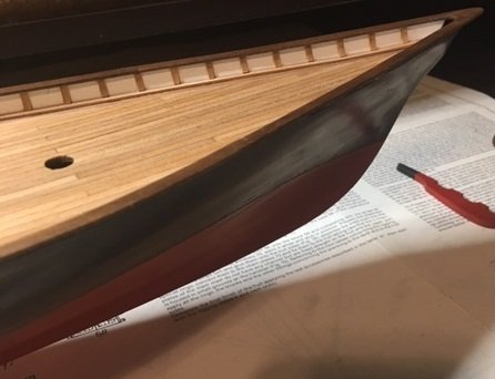
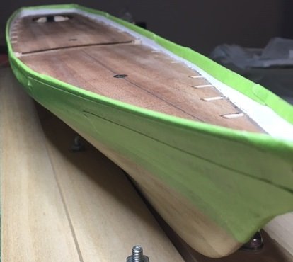
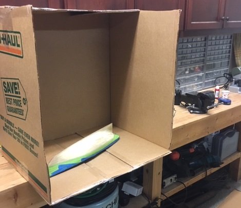
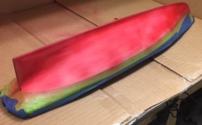
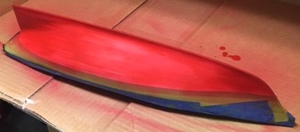
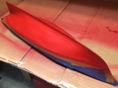
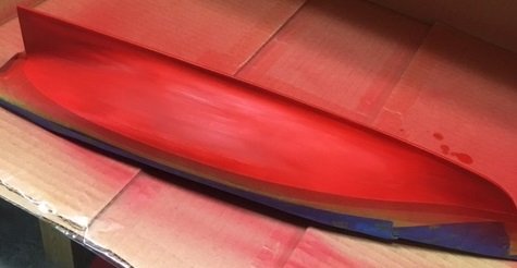
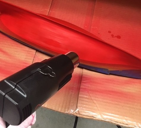
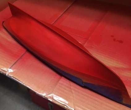
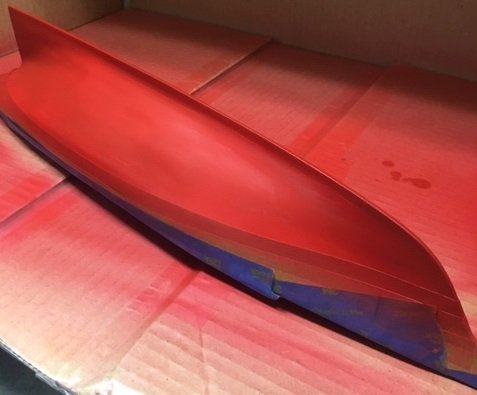
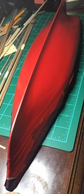
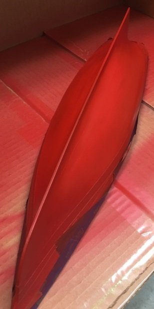
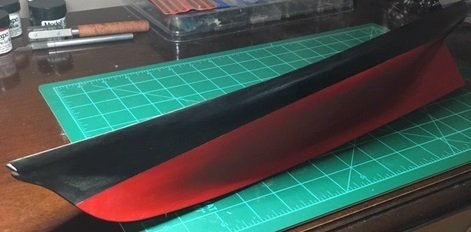
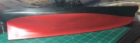
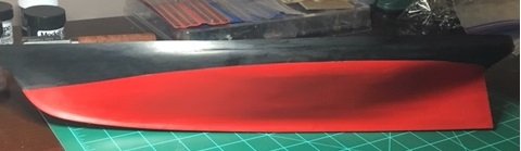
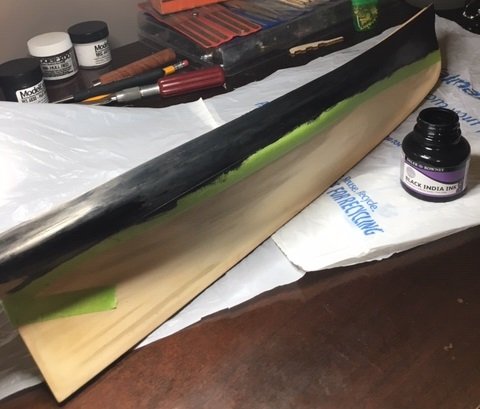
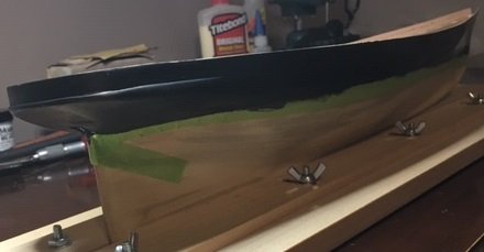
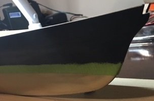
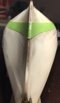
I mentioned in an earlier post that I was not going to use copper plates below the water line. I’m following the pattern that Greatgalleons used – black above the water line, red below. I realize this is not historically correct, but again, this is my first ship build and I’m trying to learn from the experience. I do not intend for it to be absolutely historically correct. I will use copper plates on future ship builds. After finishing with the black, I taped it in preparation for the lower hull painting. I used a packing box for a make-shift paint booth on my workbench. I applied 7 coats with an air brush. Here is coat no. 1. Coat no. 2 Coat no. 3 Coat no. 4 Coat no. 5. I used a heat gun between coats to speed the drying process. That worked very well - 7 coats applied in about 35-40 minutes. Coat no. 5 finished. Coat no. 6 Coat no. 7 Finished with the red paint. Here are a few shots after the tape was removed. I turned my attention to the deck planking and have added walnut strips around the inside edge of the deck. I will use cherry strips for the interior decking. That is my progress so far.
-
Referring to Greatgalleons’ build log, he used black india ink for the black portion of the hull. I like the appearance in his photos, so I purchased some and tested it on some planking along with some Hull Black from Model-Expo. I was more satisfied with the black india ink, so that is what I used.
-
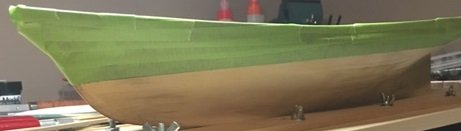
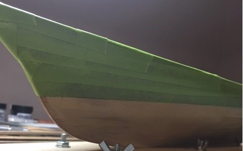
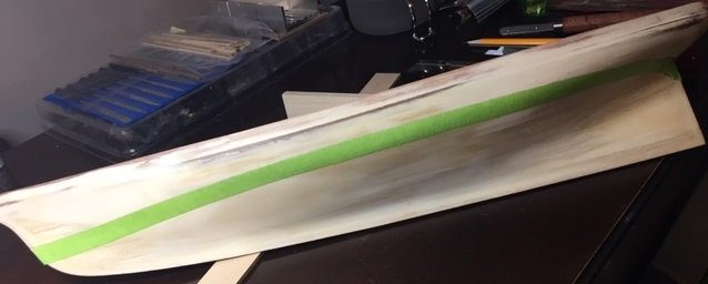
After adding some filler and final sanding, I thin marked the waterline and taped it for painting the black on the upper portion of the hull.
-
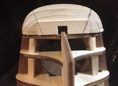
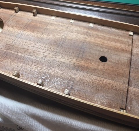
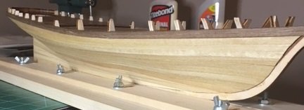
The next step I took was to trim the top of the bulkheads so they are flush with the deck.
-
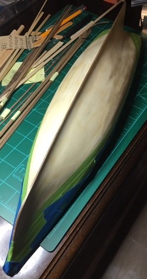
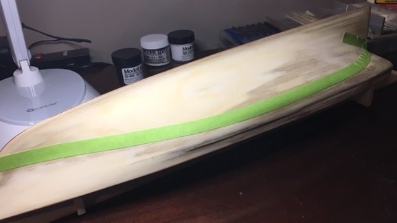
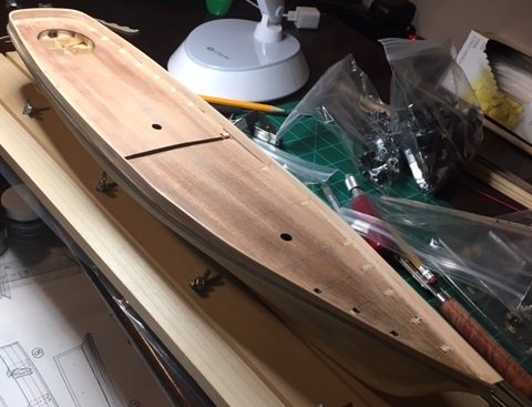
01/05/2019 With all of the summer activities and interests, gardening, work load, other hobbies, etc., I did no work on the kit between June 2018 and Sept. 2018. Once I refocused on it in Sept., I began with the strakes above the deck. I have realized numerous mistakes as I’ve progressed, which will help me on future kits for sure. One thing I noticed in looking at Greatgalleons’ build log is that when he began his planking, he began with the top strake and worked down to the bottom of the keel. I started with the strakes at the deck level, and I can see now that his approach was far superior. I added the strakes above the deck, wasn’t satisfied, removed them and did it a second time.


-
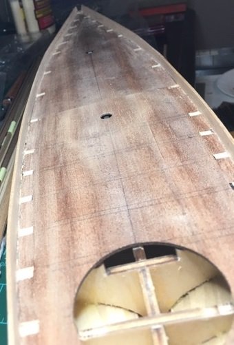
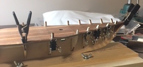
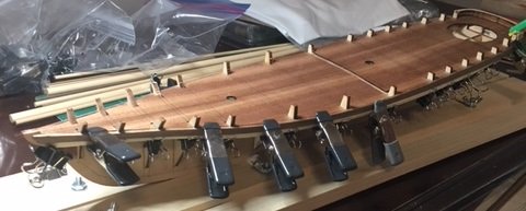
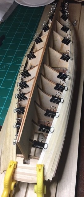
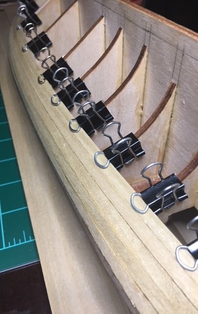
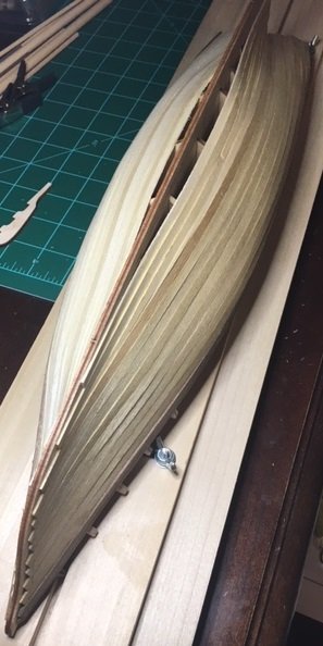
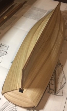
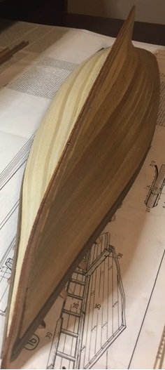
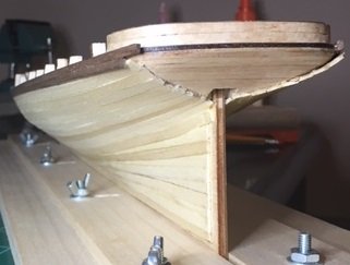
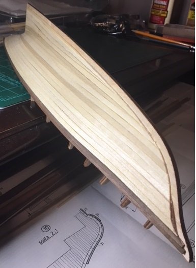
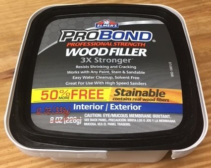
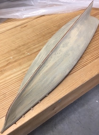
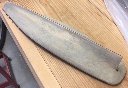
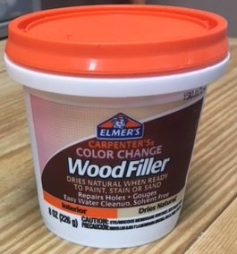
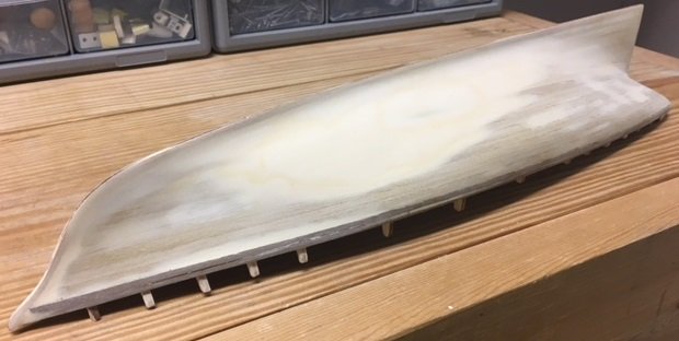
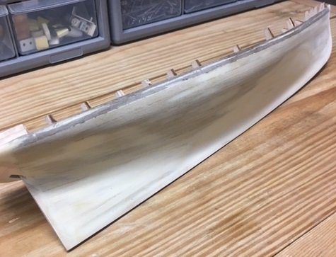
A heavy work schedule and many personal responsibilities have continued to impact the amount of time I have to work on my America kit. I worked on the planking during April and into mid-May as time permitted. Following the other build logs, I planked the stern piece first. Here is a sequence of photos of that work. The following covers many weeks of work as time permitted. After gluing the transom piece and the planking around it, I began planning the rest of the hull. After studying some of the other build logs and re-reading the instructions I decided to begin with the planking at the top at the deck level. The above picture is the completed planking and is un-sanded. The process has been a good learning experience for me. As the saying goes, you learn from your mistakes. Also, some of the descriptions and comments in the other build logs really hit home and will definitely affect the care I will take when I build my future models. I will explain some of what I am referring to. I failed to think about taking pictures from certain angles so I can only describe the problems. Without the planking on the keel and bulkhead assembly, the lines of the hull appeared okay to me. I did dry fit some of the planking, but it just did not appear to me there were any issues. As I glued each strake, the lines of the hull looked peculiar to me. The biggest flaw was at bulkhead no. 6 on both sides. Beginning with bulkhead no. 5, across bulkhead 6 and onto bulkhead no. 7 the lines sink in to the hull to bulkhead no. 6 and back out to bulkhead no. 7. The effect was there appeared to be a section sunken in on both sides at bulkhead no. 6. The depression was about 3 to 4 mm deep, and 60 or 70 mm by 120 or 130 mm. In hindsight, bulkhead no. 6 needed significant shimming that I did not do. I tried to correct it later with wood filler as other pictures will show. There were other areas where lines of the hull were not good due to the shape of the bulkheads. This goes back to previous comments I’ve made about the poor quality of the kit and the cuts in many of the pieces, combined with my lack of experience. The quality of the 1.5 x 5 mm planking in the kite was poor. I considered using other planking that I have previously purchased but decided that I would use what was in the kit. I chose to run the planking in single pieces the full length of the hull. This eventually worked out okay, however as I proceeded down the hull the angles became increasingly sharper. I soaked some in hot water to facilitate bending, but in my desire to move more quickly I stopped doing that. As the angles became sharper, I used drop planks and stealers to bring the lines of the planks into a straighter pattern so that as I approached the bottom of the keel the planks begin to line up with it. It was definitely a learning experience, and it taught that I have lot to learn. My goal was to have the planking as tight as I could make it. The bends of the planking tended to bow out the edges, but as you will see the sanding took it out nicely. Another mistake was that I did not trim the bow reinforcement pieces back enough. I did not allow for the thickness so as the planking bent up to the bow it was too think in the bow area. It’s a good lesson in how the clearances need to allow for the ends of the planking. Next, I proceeded with sanding the entire hull and trimming the planking around the transom area. I did not make any photos after the first sanding. Once the first sanding was finished I applied a thin coat of Elemer’s Probond Wood Filler. You’ll notice in the photos that this wood filler is somewhat grainy. As I sanded it down there were many small spots, and it took some time to get it smooth. I do not recommend this wood filler. The following is after sanding the first coat of wood filler. There were still numerous gaps in the planking and then there the areas such as the bulkhead no. 6 area that need to be built up. I chose not to use the Probond filler anymore and just used standard Elmer’s Wood Filler. I applied several thin coats, followed by a lot of sanding to build up the indentions in the hull. It appears in the pictures that there are uneven areas due to the wood filler. It is an optical illusion. As you run your hand down the hull it is smoother that it looks. Next, I will add the strakes above the deck planking. More posts to slowly follow as time permits.
-
Balsa in Shipmodels
TUEL replied to F24Steve's topic in Building, Framing, Planking and plating a ships hull and deck
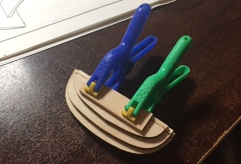
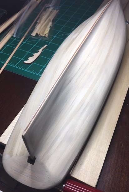
Very interesting. What is your technique for slicing the balsa to a thickness of 1/64"? -
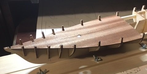
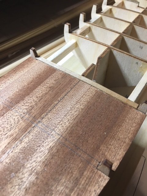
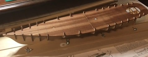
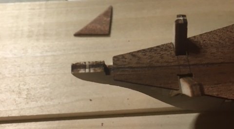
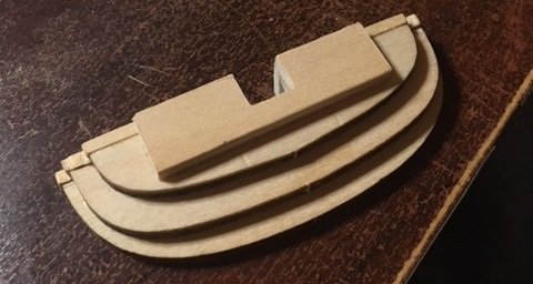
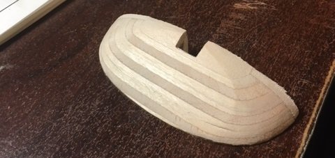
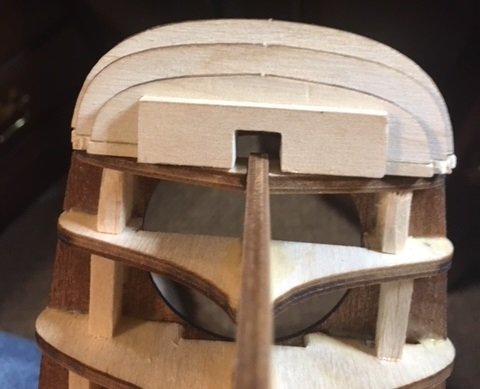
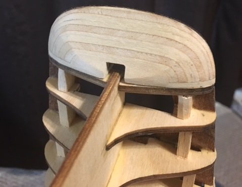
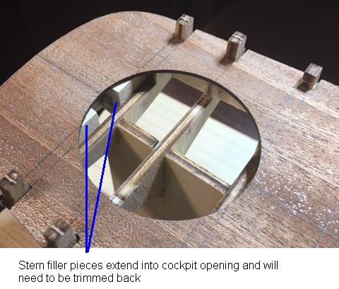
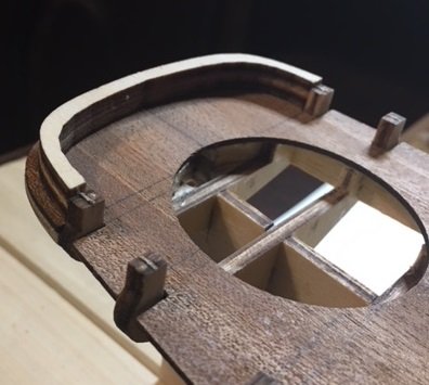
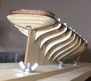
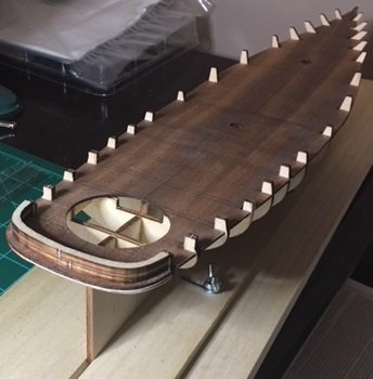
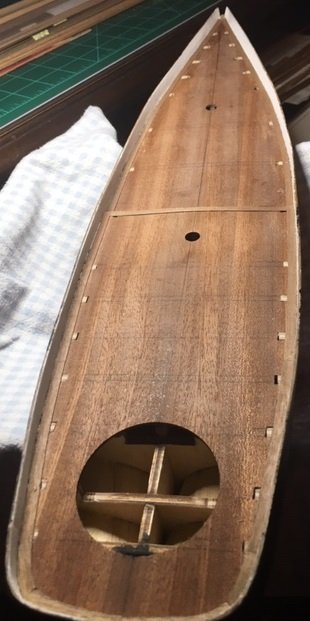
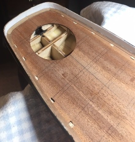
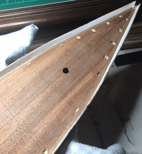
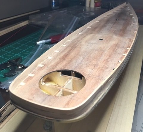
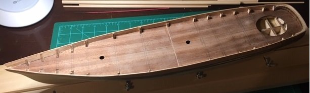
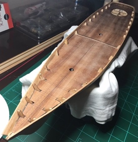
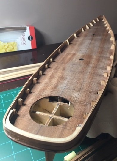
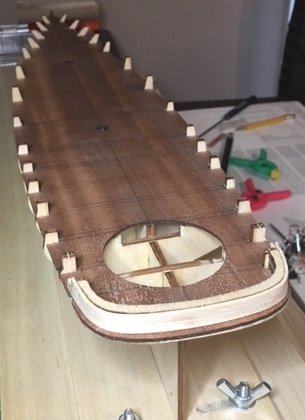
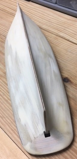
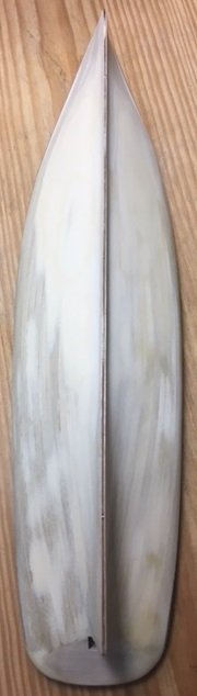
I’m finally having a little more time to work on my America kit. I glued the fore deck and the walnut strip at Bulkhead 8 as you can see below, and then glued the aft deck. Now that its glued, many mistakes are jumping out at me. I’m seeing things that I just did not notice while I was dry fitting it. An example is Bulkhead 12. It appears now that it was not uniform in shape on both sides and is slightly shifted toward the starboard side. Had I noticed it rotating it 180 degrees may have corrected it, or I could have spent some more time shimming it. Another point learned is that the dry fit is a loose fit, but once it was glued everything functions as gusset plates. It becomes completely stiff and I found myself sanding in various places to make it fit. This is great information for me on my future builds, but as for this one I’ll just try to adjust it as best I can. The fore deck was a little short at the bow so I cut a small piece from the sheet and glued it in place, then sanded it as you see below. I shaped the bow fillers and glued each in place on the starboard and port sides of the bow. The stern filler pieces required quite a bit of effort. As I’ve commented on several occasions, this is my first kit build and so I’m learning as I go. I’ve looked at several different build logs to see how this part of the kit was handled by others and then just took my best shot at it. Here is the sequence if how I assembled and glued it. In the picture above, you can see that I added two pieces of basswood to the inside next to the notch for the rudder. I decided to do this after test fitting and then reviewing the drawings, and then reviewing pictures in other build logs. The filler pieces helped the stern filler to align with the end of the aft deck. It also, seemed to me that it needed another layer to align properly with Bulkhead 15. In this picture I’ve added another piece of basswood that is about 35 mm x 12 mm. After the glue had time to set, I cut the notch for the rudder out on my band saw. Here is a test fit of the assembly of the transom assembly. I penciled lines for guides while sanding. I wasn’t comfortable using a Dremel tool or powered sander to shape the transom piece. My preference was to sanded by hand so that I could go slow. It’s better to me to do that then to take to0 much material off. Here is the transom piece completely sanded. I’m not sure that the shape is what the designers intended, but as I said this is my first shot at doing something like this. Here it is glued into place. As you can see it need some additional sanding to fit correctly. I noticed after I glued it into place that part of the transom piece extends into the cockpit as you can see here. I’ll trim this back. I wish I had noticed this before I glued it in. It would have been much easier to trim back, but no choice now but to trim it in place. I next glued the stern pieces to the aft deck and trimmed the stern filler pieces that were extended into the cockpit opening. I’m close to starting the planking. That will be a new adventure as well. That’s all for this post.