TUEL
-
Posts
55 -
Joined
-
Last visited
Recent Profile Visitors
1,107 profile views


-
 Mirabell61 reacted to a post in a topic:
America by TUEL - FINISHED - Mamoli - Scale 1:66
Mirabell61 reacted to a post in a topic:
America by TUEL - FINISHED - Mamoli - Scale 1:66
-
Mirabell61 reacted to a post in a topic:
America by TUEL - FINISHED - Mamoli - Scale 1:66
-
GrandpaPhil reacted to a post in a topic:
America by TUEL - FINISHED - Mamoli - Scale 1:66
-
Papa reacted to a post in a topic:
America by TUEL - FINISHED - Mamoli - Scale 1:66
-
egkb reacted to a post in a topic:
America by TUEL - FINISHED - Mamoli - Scale 1:66
-
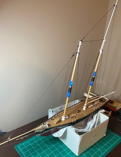
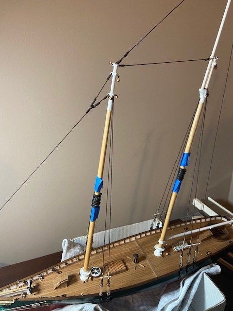
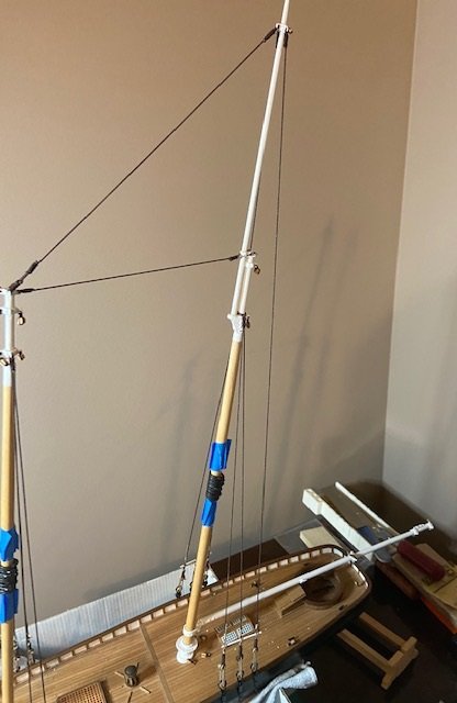
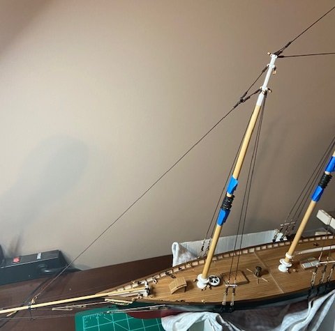
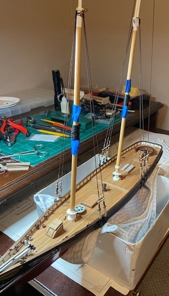
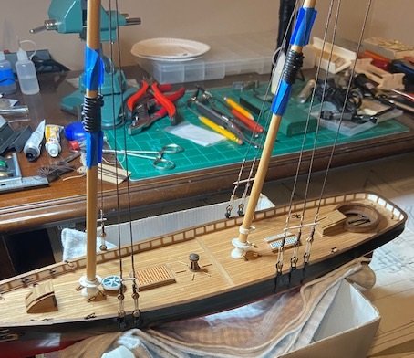
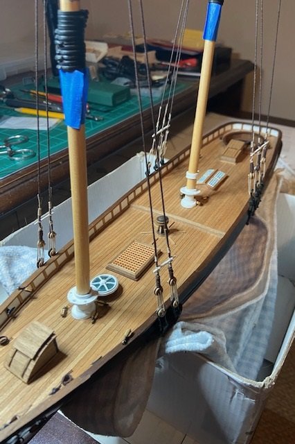
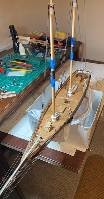
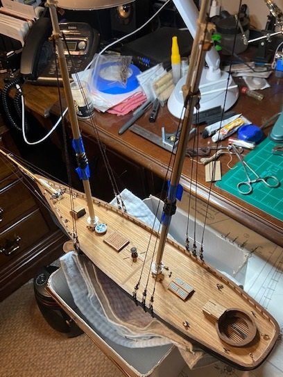
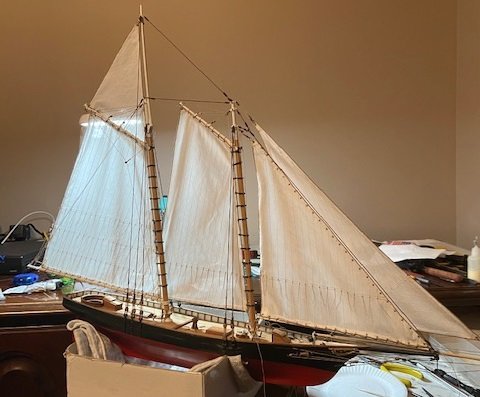
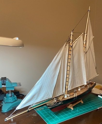
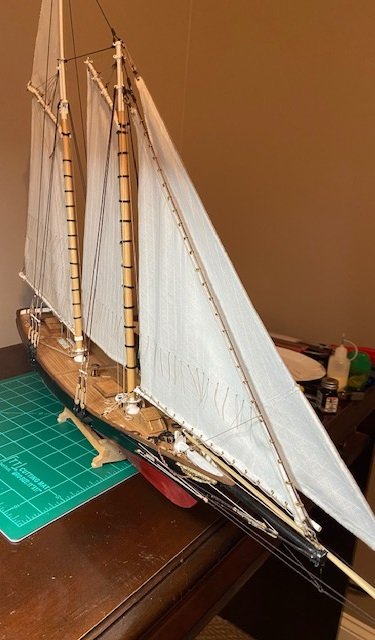
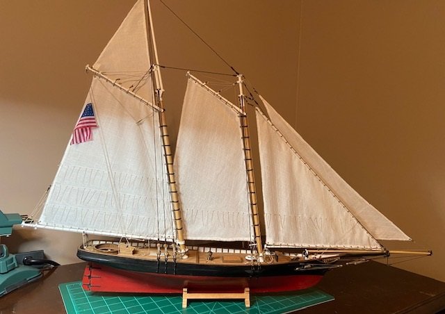
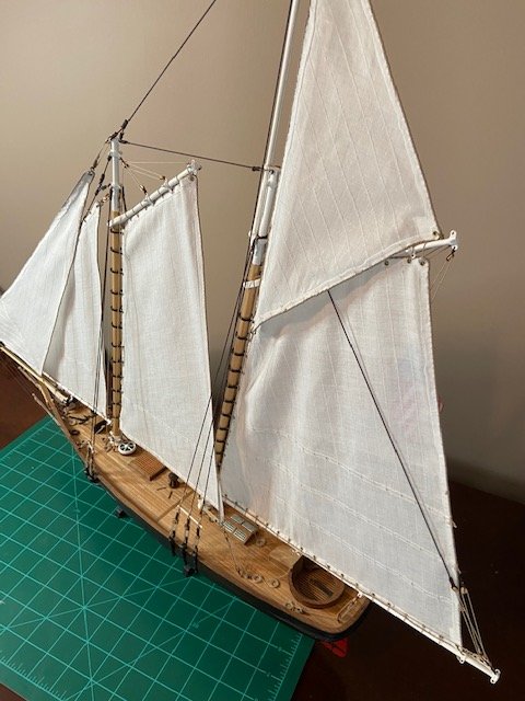
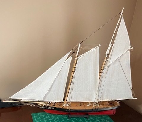
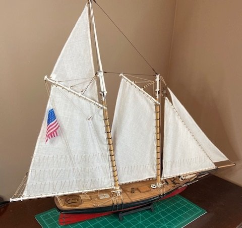
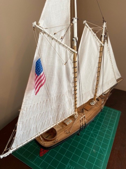
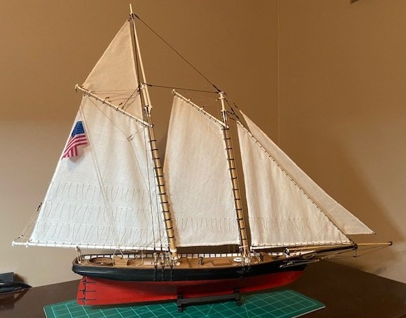
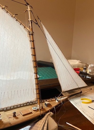
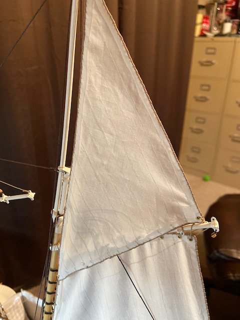
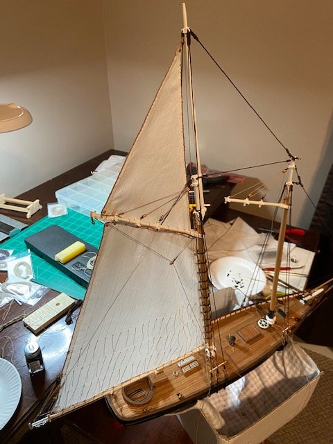
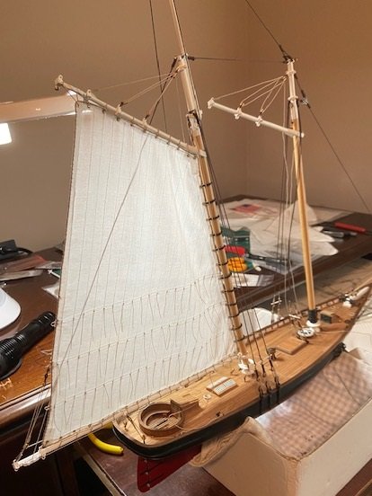
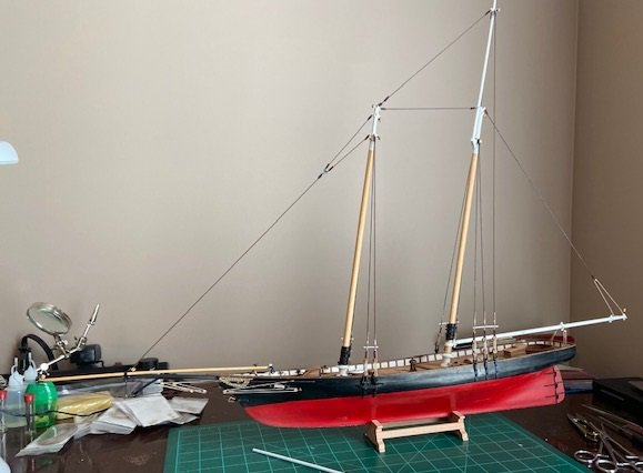
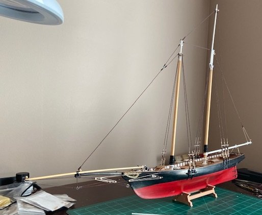
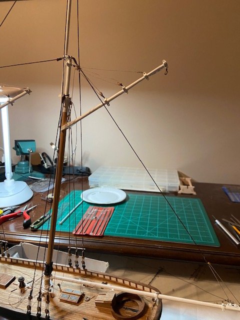
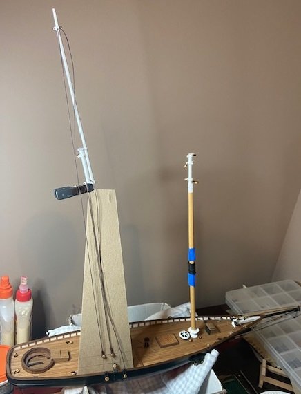
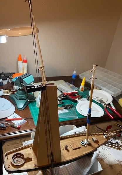
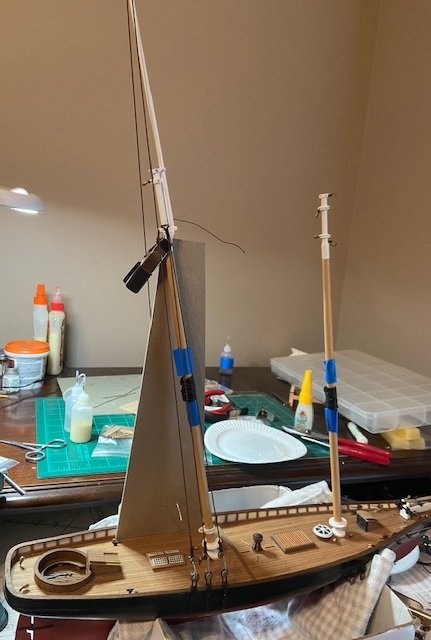
Thanks Bradley! After cleaning up the loose rope and securing it to the various cleats, I mounted the boom to the staysail and installed the rope around the boom. Next, I rigged the staysail onto the mast and installed the rope to secure it to the main mast and the bowsprit. Next, I installed the brass rings on the upper part of the staysail. Here are some pictures with the rope completed around the staysail. Once the staysail was mounted, the last thing two things left were to paint the stand, and to make an American flag that was accurate to the 1851 timeframe of the ship (with 31 stars). The flag included with the kit was not acceptable. It a Betsy Ross flag (13 stars) from 1776 and does not look the least bit realistic. It’s hard to understand why Mamoli would not consult the history books and know this flag was not accurate. The flag included in the kit looks to be screen printed with high gloss cloth and ink and is only printed on one side. Very poor example. I began googling to try to find an accurate, properly sized flag that could be purchased, but just couldn’t find anything to suit me. From there I began researching methods to make my own flag and have found a method that I know I will use over many times going forward. I found the method I used in a post on Sept. 25, 2017 on the Model Ship World forum by member Chuck in his build log for the HM Cutter Cheerful. Another member commented on his flag and asked how he made it, and that is the method I used on mine. For context, I’ll repeat it here. The flag is made from the tissue paper you use to pack boxes or maybe a gift. Many people use this as filler in gift bags. Its white, and is very thin. My wife keeps boxes of gift paper and had some of this tissue paper so that is what I used. I made a PNG file of a flag I found on line that is the 1851, 31-star flag. I did a screen print and saved it to the clipboard, and then I used Microsoft Paint to resize it and clean up the edges. I determined the size I wanted through several test prints using an HP 7150 ink jet printer. I printed it on 24 lb paper so that it would be a little stiffer than normal. I determined the size I would use by measuring the flag provided in the kit and used those dimensions. After printing the flag to the size I wanted, I cut a piece of the tissue paper about ½ inch larger on the sides than the size of the flag, then taped the piece over the flag image on all four sides. I reinserted that sheet into the printer and reprinted the flag. I let it dry for a few minutes and trimmed the tissue paper very close to the edge of the flag, with no white space on the edge. The tissue paper is so thin that the ink will soak through to the other side but not entirely. I then immediately sprayed the reverse side with Krylon Matte Fixatif (which I had purchased at my local Hobby Lobby). Per the post by Chuck that I am referencing here, you should not be afraid to spray too much. This facilitates the ink soaking through to the back side further and it will look like it is literally printed on both sides. Then after it dries flip it over and spray the front side. Next you can shape it to suit, perhaps using various size dowels. You can also spray the fixatif more to really soak it because this makes it easier to shape...you can do this several times if need be. Once dry it holds its shape. Next, I placed some tape (I lapped the tape so that is was maybe 1mm x 2mm) just over the corner of the flag on both side to hopefully strengthen it a bit, then punched holes with a large hat pin to thread the halyard rope through. So, I now come to this point where I can now say that I am finished. Here is a picture from yesterday with the stand not painted. Here are some subsequent pictures from different angles after painting the stand. I’m thinking I’ll do one more post in a day or so and maybe list some observations and lessons learned. I’m glad to get to this point and looking forward to my next build. As soon as time permits, I will post pictures of the finished ship in the gallery. Thanks to everyone who followed my build log and commented.
-
Papa reacted to a post in a topic:
America by TUEL - FINISHED - Mamoli - Scale 1:66
-
egkb reacted to a post in a topic:
America by TUEL - FINISHED - Mamoli - Scale 1:66
-
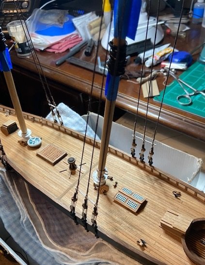
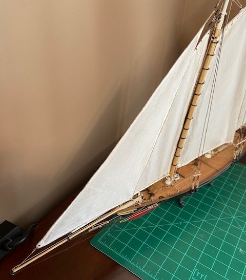
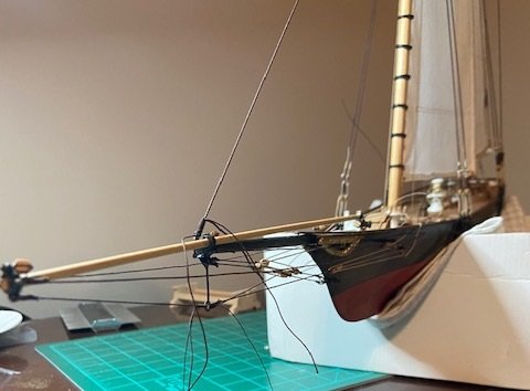
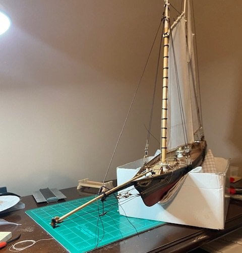
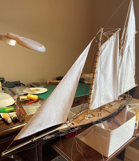
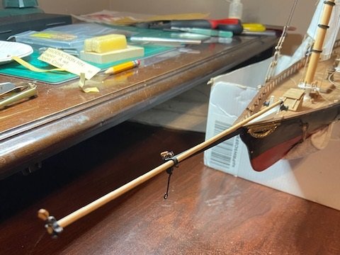
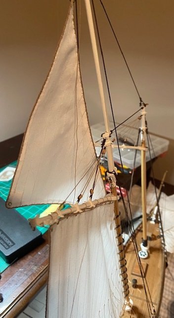
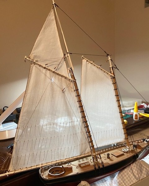
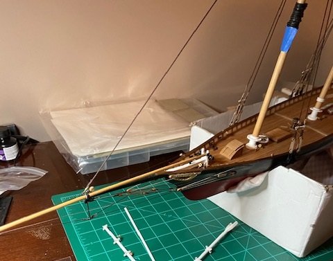
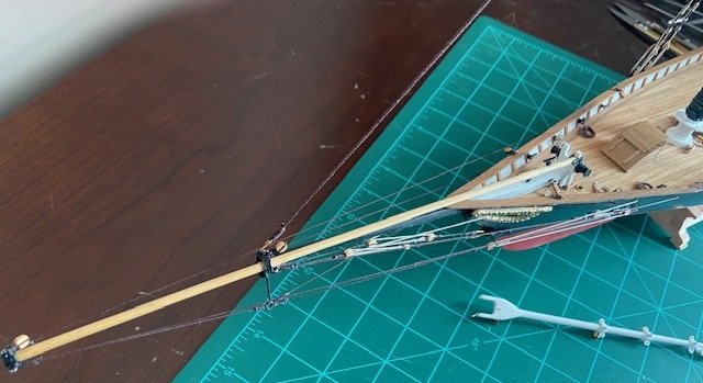
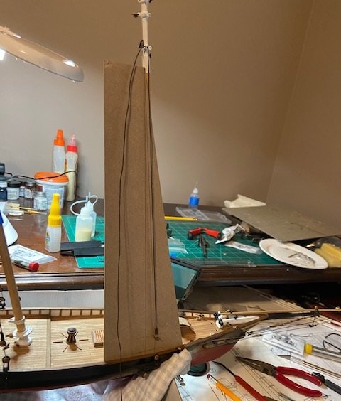
I continued with rigging the repaired bow. I left some of the rigging below the bowsprit loose so that when I added the jib sail I could tighten them simultaneously with the rigging on the jib sail. Here is the jib sail completed with the rigging tightened down and secured. I’m now cleaning up the loose rope and will then mount the staysail.
-
Vladimir_Wairoa reacted to a post in a topic:
America by TUEL - FINISHED - Mamoli - Scale 1:66
-
egkb reacted to a post in a topic:
America by TUEL - FINISHED - Mamoli - Scale 1:66
-
robdurant reacted to a post in a topic:
America by TUEL - FINISHED - Mamoli - Scale 1:66
-
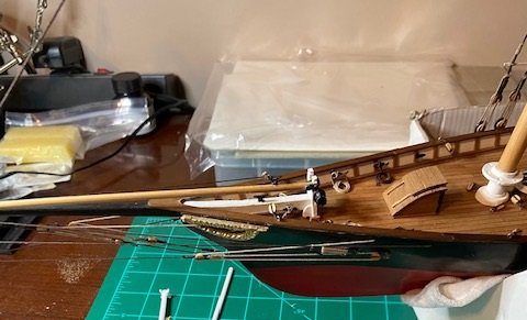
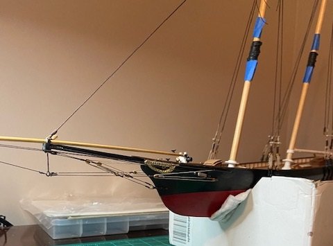
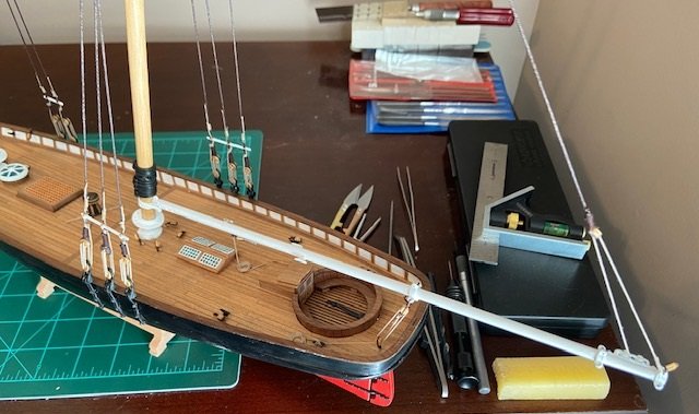
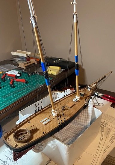
It’s been a little over a month since I last posted. I took a hiatus from the build after my crack up I showed in my last post. I’ve posted in the past that we also plant a large vegetable garden and we’ve been picking and canning vegetables the past several weeks, so there really wasn’t much time to work on the ship. I’m back focused and have progressed on rebuilding the bow area. Here are a few pictures. I’ll re-rig the bow area over the next few days and then continue with mounting the sails.
-
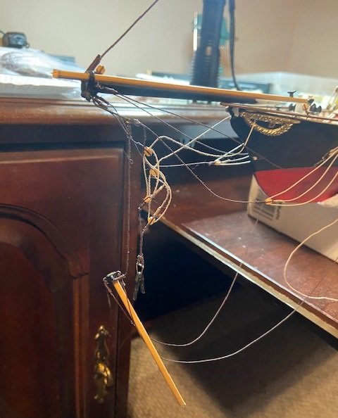
Thanks md1400cs! I continued the rigging of the sails. Then, I had a significant setback. I turned my chair around and the armrest caught the edge of the ship, and off onto the floor it went, bow first. I haven’t worked on it for a over a week. One step forward, two steps backwards. I’ll start repairs in the next couple of days, but still pretty frustrated.
-
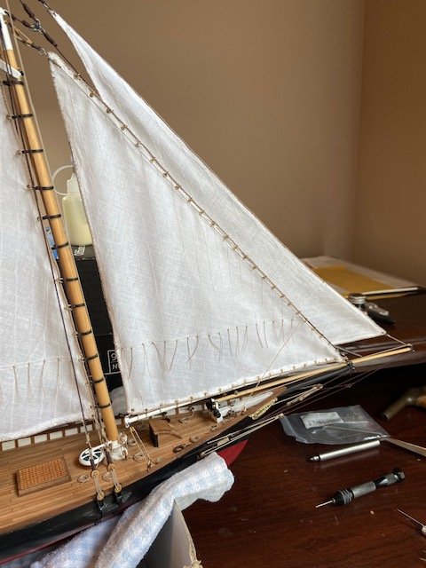
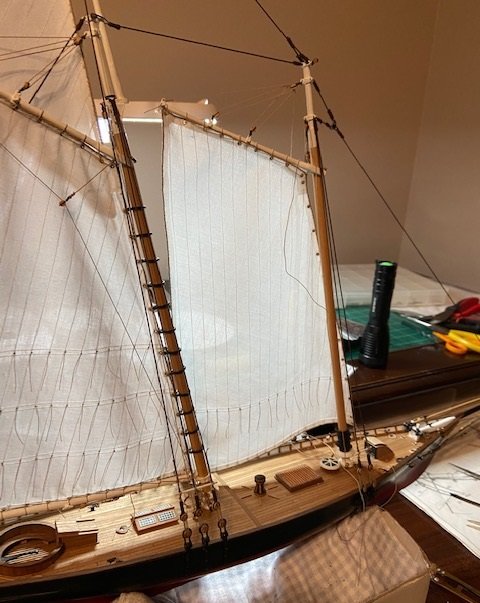
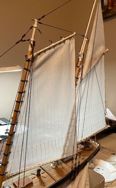
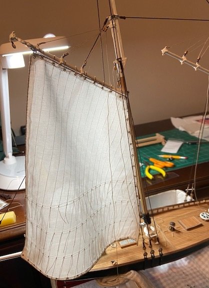
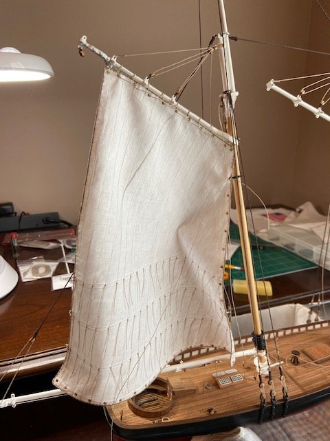
I ordered some additional .045 rope from Syren. I was selecting the rope I noticed they offered 0.20mm rope. I decided to include that in my order because I thought it would be a better choice for seizing the 0.45mm line I’ve been using. Once I received it was the correct size for the reefing lines. I proceeded to use it for the reefing lines on the mainsail, foresail and staysail. Here are the finished reefing lines on each of the 3 sails. Once that was complete, I began rigging the mainsail. Here are a couple of pics showing the progress. Here is the finished mainsail. In the process of working around the rigging and sails, two of the chain plates on the starboard side have come loose. Looking a little closer, it’s the same problem I’ve had before with the fatiguing of the white metal. I anticipated this and ordered some brass strips of various widths a few weeks back. I fashioned two replacements from the brass. It was so significantly easier to work with and I have now replaced the two failed chain plates. Now I will turn my attention back to sail rigging.
-
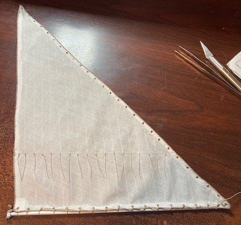
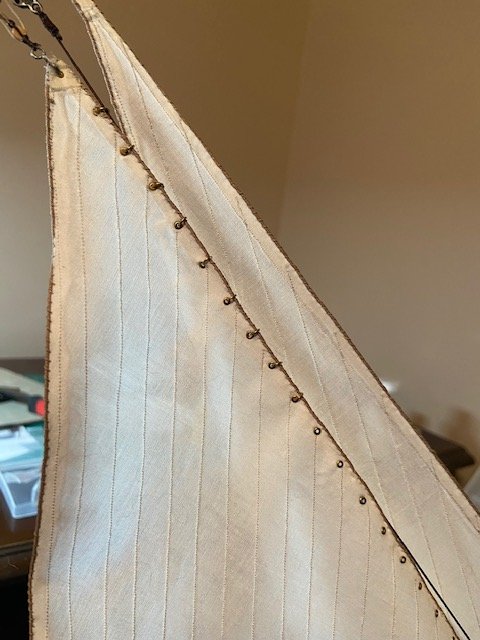
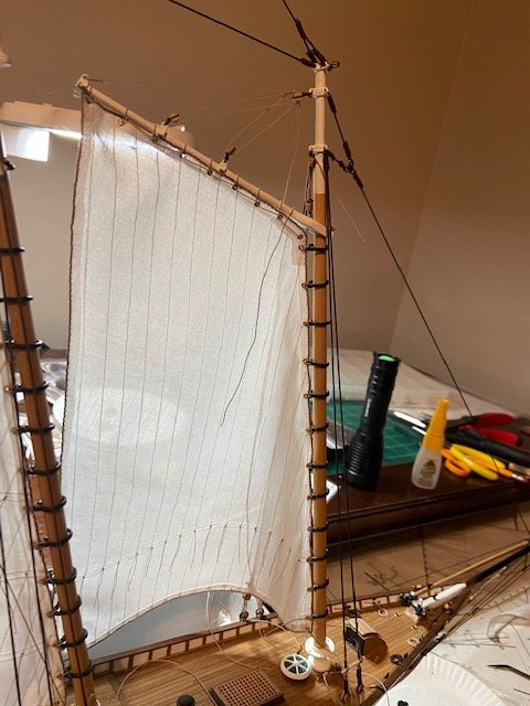
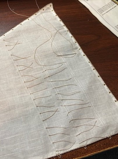
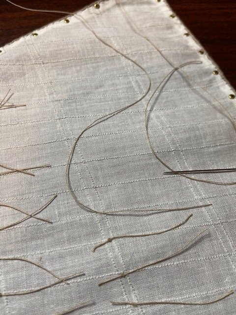
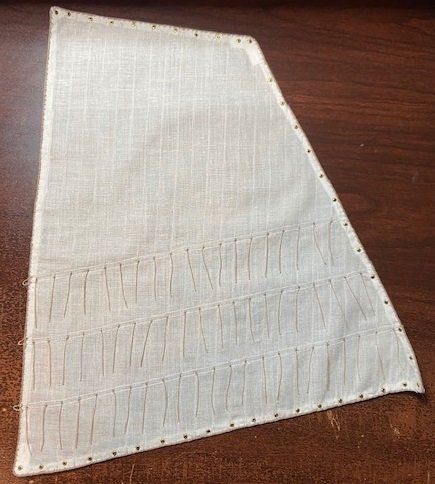
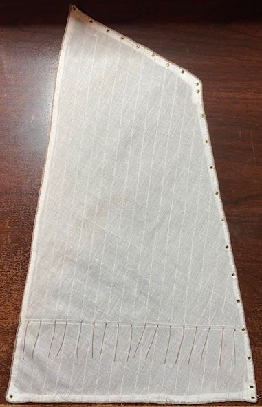
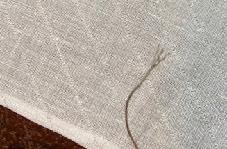
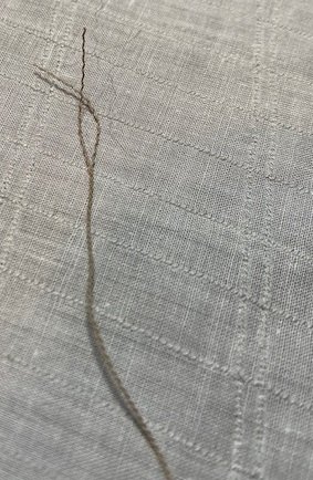
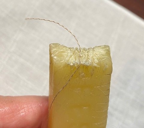
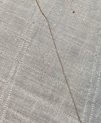
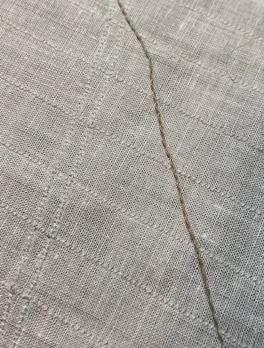
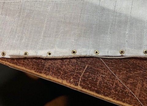
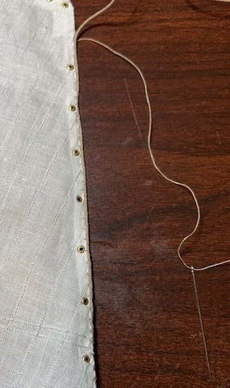
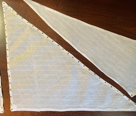
I’ve been purchasing all of my rope from Syren. Not knowing how to estimate it, I’ve had to order more 3 different times. It’s a bit expensive so I was trying to optimize it with each order, and I probably spent too much on shipping trying to do that. I’m using tan and brown rope, mostly 0.45mm diameter. As I began seizing around the blocks, I used some thread that I found at Hobby Lobby for the seizing. That thread matched somewhat, but it had a bit of a gloss to it and it just didn’t match well enough to suit me. The 0.45mm rope is made from 3 threads twisted together. I realized that I could untwist the rope and separate the 3 threads, then use that thread for seizing. It appears to be an optimum size, and the color matched perfectly to the rope you are seizing. Here are a few pictures of the first step of untwisting the rope. Once it is separated, it still has a twist in it as you can see in this picture. I found that if I would pull the thread through bee’s wax several times it begins to take the twist out until it is relatively straight. The down side I found is that it loads the thread up with wax, which in turn makes it somewhat sticky. That makes it a little harder to work with, but the results are still good. I began the process of stitching the rope to the edge of the sails. I used 0.88mm rope for the edges of the sails. As I worked through this, I separated the 0.45mm rope into threads, pulled it through the was until straight, and just sequenced through the stitching in that manner. Here are the sails with the 0.88mm rope attached to the edges.

-
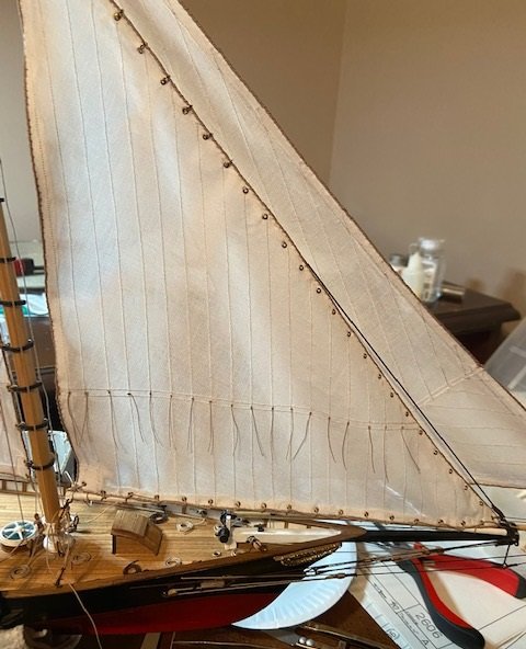
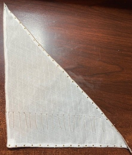
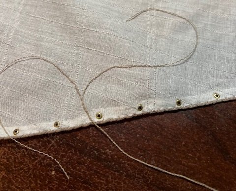
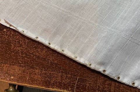
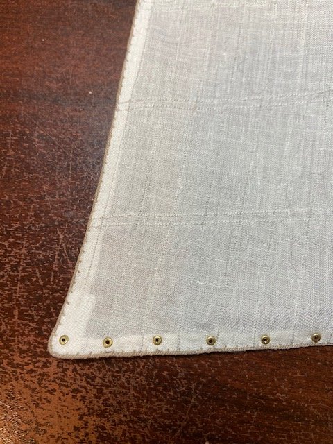
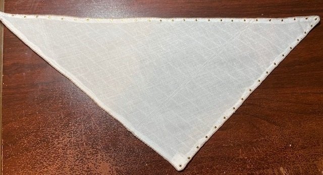
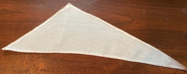
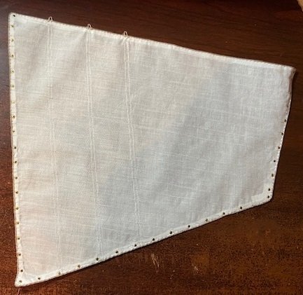
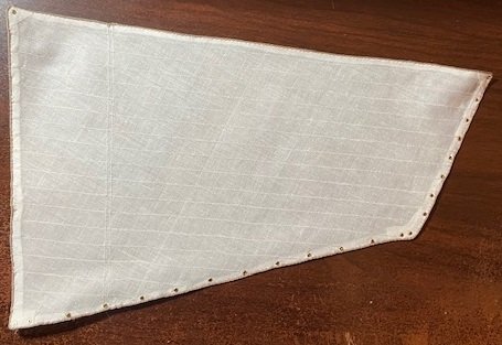
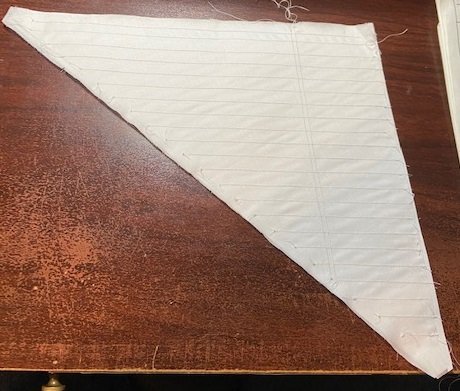
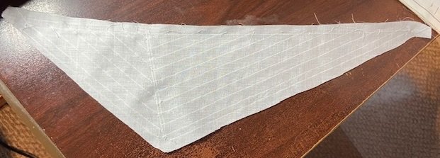
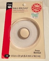
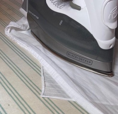
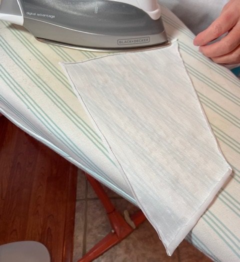
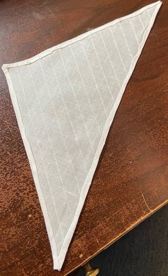
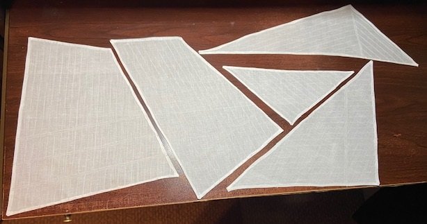
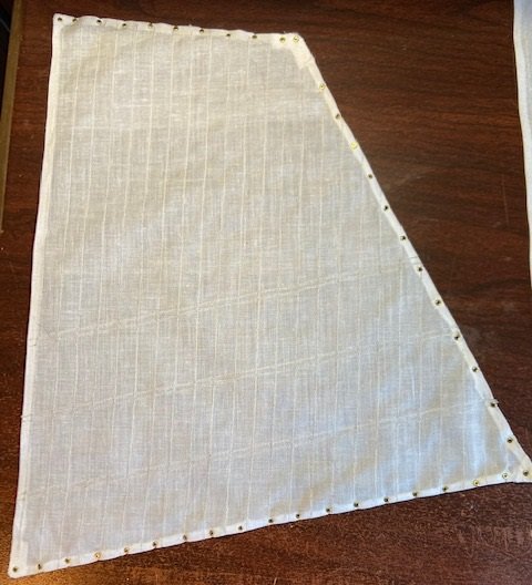
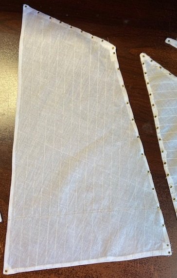
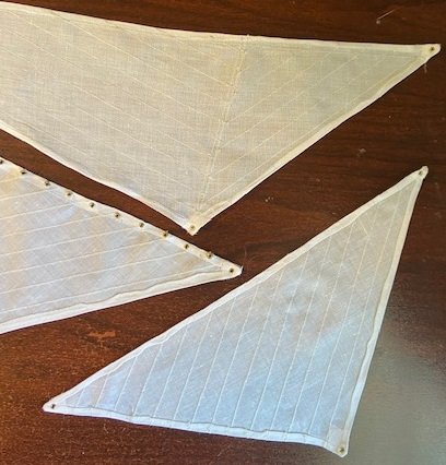
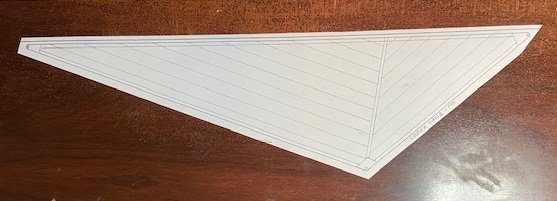
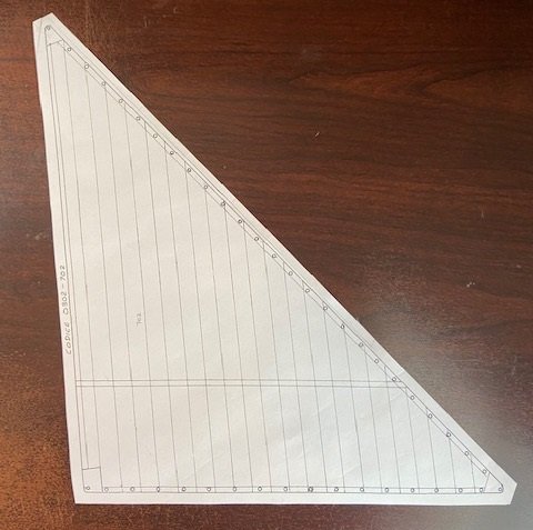
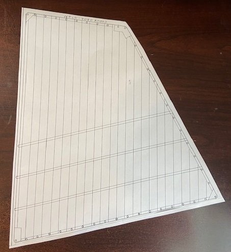
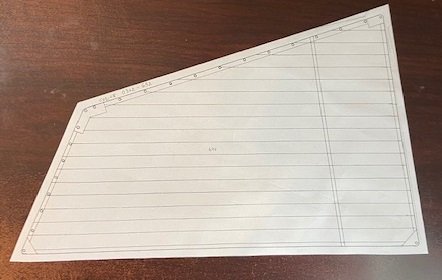
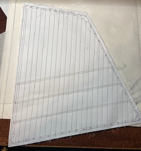
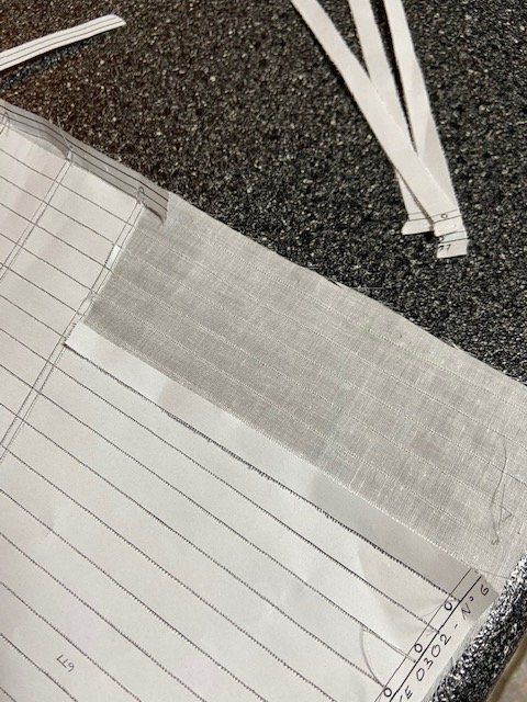
I made an extra copy of the sail patterns when I made the original copy, so I was able to use those to overlay the sails. This allowed me to determine how I would handle edge, and also to locate the position of each eyelet. I decided that I would try to make a finished edge on the sails. To do this I would need to allow enough extra around the edge of each sail to allow it to overlap twice. The drawings show a 3mm edge, so I cut the edges 6mm from the edge of each sail. My wife helped me a great deal with the sails and after we worked with a couple of the sails, we realized that 6mm wasn’t enough, but by then the cuts had been made (measure twice, cut once sure applies here). I used a product named Stitch Witchery. This is a bonding web for fabric and can be purchased in various widths. It is a polyamide fusible bonding web material that is heat activated. We cut it to the correct width, placed it between the fold of the sail fabric, placed a damp cloth over it and ironed it. I think it is much superior to trying to glue the fabric because it allows you to have just enough bonding material to bond the fabric, with no permeating into the cloth. Here is one of the sails completed. I wasn’t really satisfied with it. I believe we cut the edge too tight, and consequently it was very difficult to keep it straight. Also, the bonding material appeared to shrink and pull it in in some places. This experience to file away and use on the next build. Here are all of the completed sails. I turned my attention to the eyelets. The issue with this kit is that the eyelets are very tiny (~1-1.5mm). I think I need a 1mm tool to set them, but if that tool exists, I can’t find one. As a compromise, I purchased a 1.5mm tool. This tool has to be inserted into the eyelet and hammered. My preference would have been to find a plier type setting tool, but I wasn’t able to find one for this size of eyelet. The setting of these eyelets was not a good experience for me and I was not pleased with the quality of my work. I spent some time trying to find information as to the procedure for setting the eyelets. I was not able to find a great deal of information on MSW. There are plenty of comments about eyelets and pictures, but practically nothing on setting them. I did numerous Googles just trying to find some guidance but didn’t find much. I used the extra patterns to overlay the sails and mark the location of the eyelets on each sail. I didn’t make any pictures of that process, but I started by make a pin hole in the center of each eyelet location. Next, I used a sharp pencil to mark the cloth with a dot beneath each pin hole location. I have a soldering aid tool that has a chisel on one end and an offset awl on the other. I found I could place the sail over some hard cardboard, and use the awl end to punch a hole at the eyelet location. I would set the eyelet in the hole, turn it over and then use the eyelet tool to hammer the end. The I would use a small hammer to flatten it the rest of the way. I had a lot of issues due to the setting tool being a 1.5mm size, and some of the eyelets did not collapse evenly. Once that happened, I had to remove the damaged eyelet and set another one, sometime damaging the cloth around the hole. The kit came with 138 eyelets, and the sails required 115. When finished I had 3 eyelets left over. My next step is to attached the rope around the edge of each sail.
-
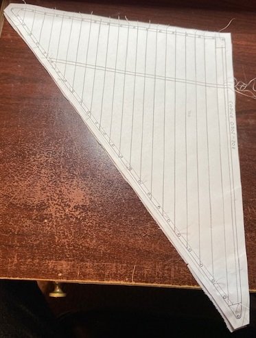
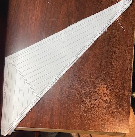
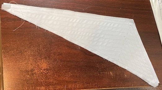
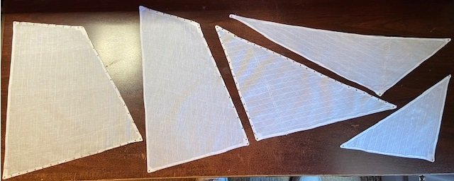
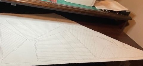
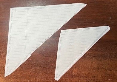
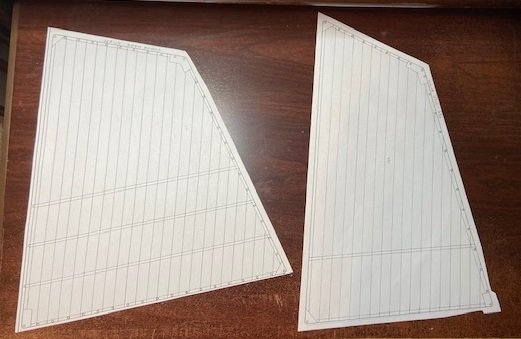
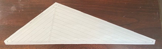
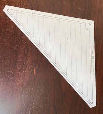
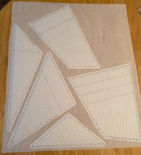
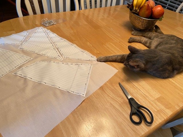
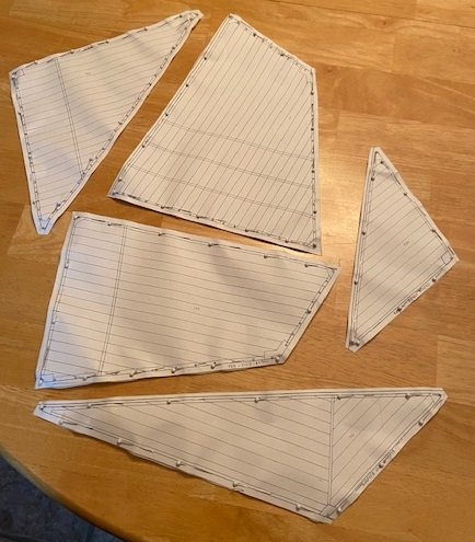
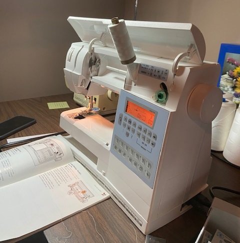
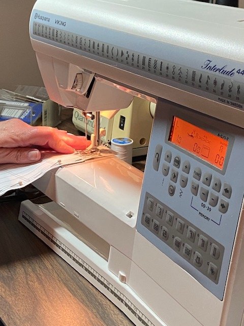
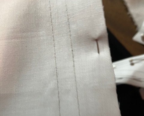
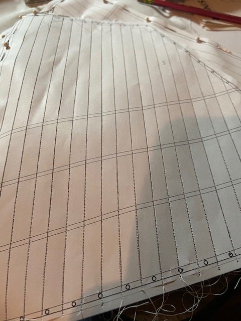
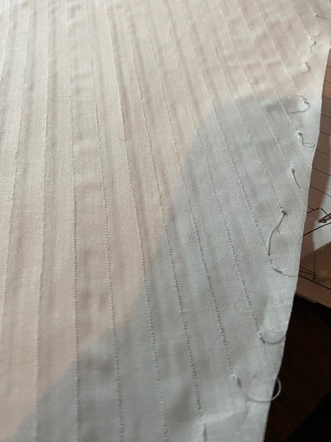
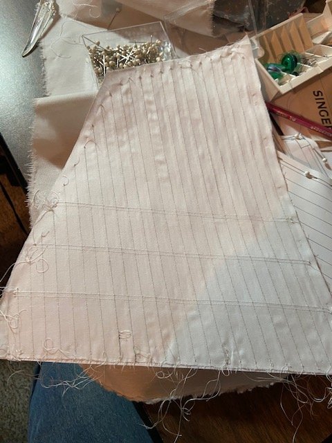
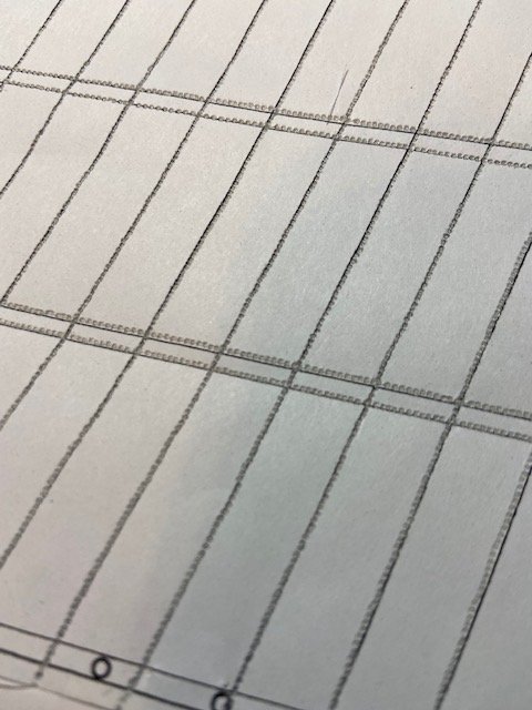
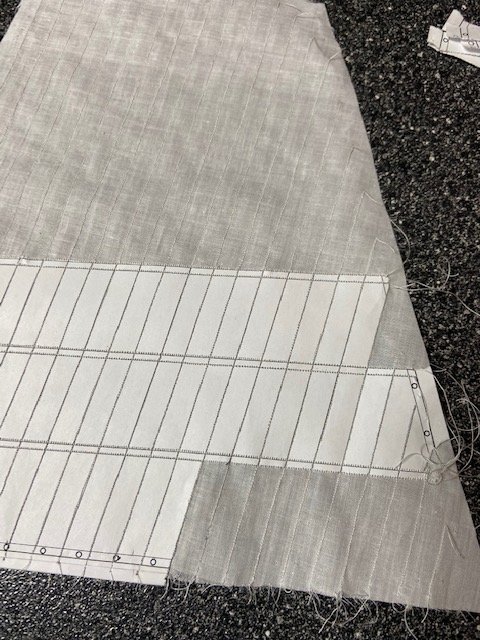
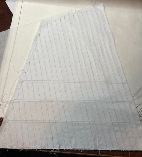
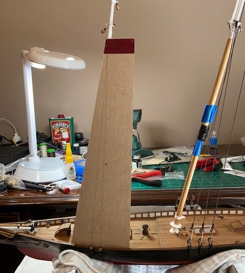
My approach to the sails was to make a copy of each sail to use as a pattern to mark and cut the cloth, and for the location of seams and eyelets. My first step was to make a copy of the sheet with the sails printed on it. My first attempt was to use my laser printer to make the copy of each sail, however it would only print 8.5”x11”, and most of the sails would not fit on one sheet. I probably could have used 8.5”x14”, but I would still have to piece each sail copy together. I copied portions of each sail with the intention of taping the pieces together to make the full sail pattern. My seamstress wife advised me that it would be much better to have each sail pattern on one sheet not pieced together. I took the plan sheet to a local copy/shipping store and had them to make two copies of the sheet, then cut away the portion with the sail patterns on one of those copies. Next, I cut each individual sail from the sheet. I continued to look at the build logs of Hamilton, Greatgalleons and Flyer. Hamilton provided very few pictures and limited comments in regard to the sails. The other two have more detail, and that was helpful. One of the build logs showed the edge of each sail being folded over once, but being left unfinished. The other log showed the edge being cut, folded over and glued, also unfinished. I showed these to my seamstress wife, and her recommendation was to fold each edge over twice and stitch it so that it has a finished edge. Looking at the patterns in the pictures above, you notice that some of the edges are not even. This was due to the position on the plan. Looking at the edge of each sail, it shows a 3mm overlap. To fold it over twice I needed 6mm on each edge to allow for two 3mm folds. I cut pieces of paper and taped to each edge where necessary, then cut each sail to have 6mm from the edge of the sail. Here is the result of each sail pattern, with the 6mm edge. Next, we pinned each sail to the cloth included in the kit. I needed help and advice, but this is not what I had in mind. Here are the sails pinned to the cloth and cut, allowing for the 6mm edge. I had planned to attempt sewing the seams and edges, but my wife wants to do it so she has a contribution to the ship. She has a Husqvarna sewing machine with a lot of features and adjustments. After a couple of test seams, we decided a stitch length setting of 1 had the best appearance. My approach is to use the paper pattern pinned to the cloth as a guide for the seam locations. Here is the reverse side of the seam. This is the completed sail. We realized through the testing that the sewing machine needle perforates the paper, so it should be easily removed. This is the reverse side from the paper. As you can see here, the sections of the paper are easily removed because of the perforation in the paper made by the needle. That’s it for this post.
-
TUEL reacted to a post in a topic:
America by TUEL - FINISHED - Mamoli - Scale 1:66
-
TUEL reacted to a post in a topic:
America by TUEL - FINISHED - Mamoli - Scale 1:66
-
Phil, Thanks. It's definitely been a good learning experience. I really expected a learning curve here so my frustrations are limited. I'll definitely know what things I need to do better on the next build. I'm sure that will be another learning experience too. I voice frustrations, but I've really enjoyed building this kit. Tim
-
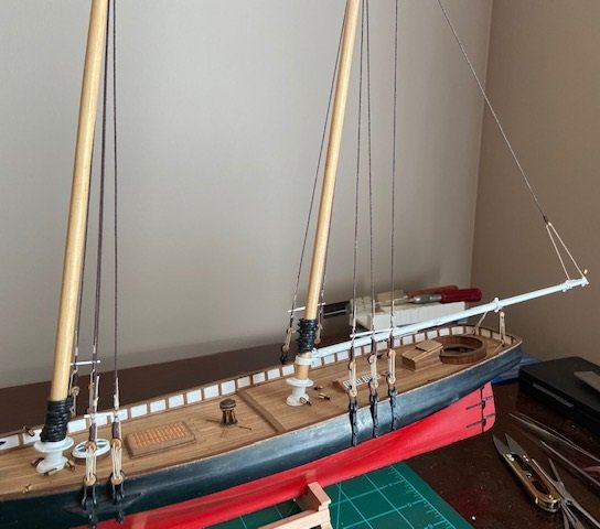
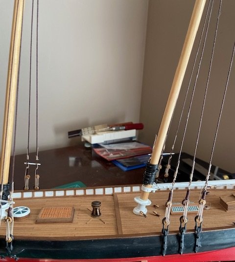
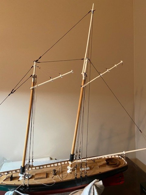
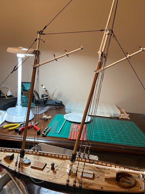
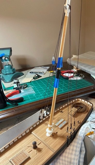
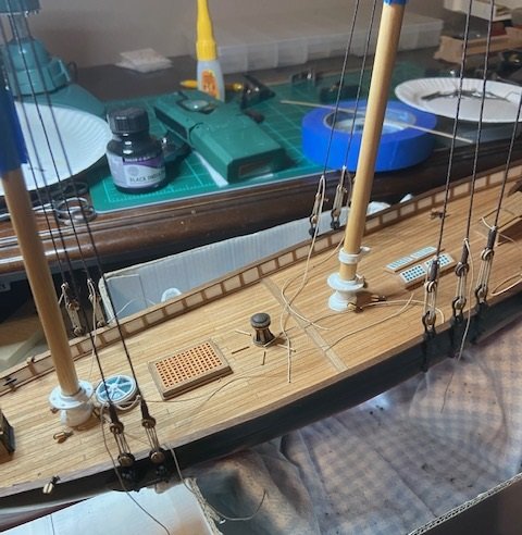
I have completely replaced the rigging underneath the bow. Some of the rigging came lose or was knocked lose as I was repairing the bowsprit. I wasn’t pleased with the seizing on most of the rigging in this area so I opted to replace it. Here are a few pictures of the re-rigging. I completed the rigging around the spanker boom and stern area after completing the bow. Here a few pictures of this stage made with a little better lighting. I next attached the two gaffs and finished the rigging on those as you can see in these pictures. It doesn't seem like a lot of progress since my last post, but it was time consuming to me. I am now turning my attention to the sails. I am fortunately married to an excellent seamstress, so I will rely heavily on her guidance (as I always do) and her first class high dollar sewing machine.
-
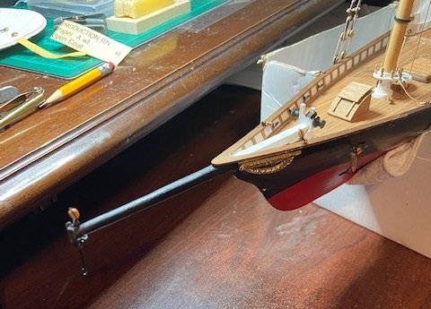
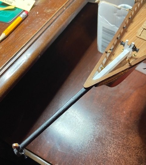
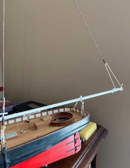
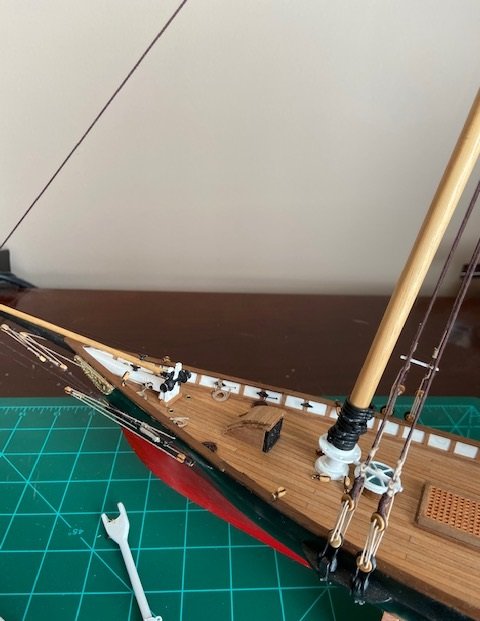
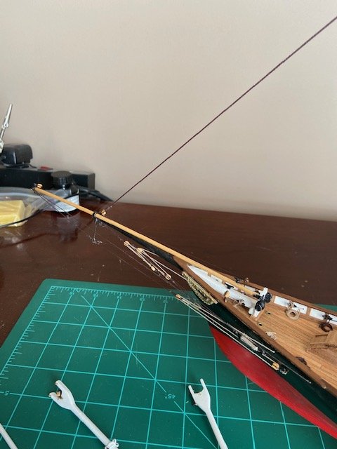
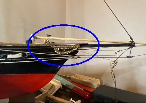
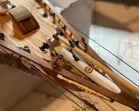
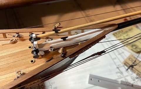
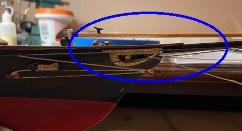
I had an issue with the bowsprit as I added rigging on the masts. When I first began the rigging around the bowsprit and the bow, the bowsprit broke loose from the deck due to the torque I was placing on it while tightening the rigging rope. This happened at least twice, maybe 3 times. At that time, I felt I did not have enough surface contact to get it securely glued, and I added a strip under the bowsprit and used epoxy rather than wood glue. When I added the rigging rope to the mast and down to the bowsprit, the torque placed on it once I tightened it up pulled the bowsprit loose again. My thinking was that I had made a rookie mistake of not anchoring the bowsprit or not having an adequate glue surface to hold the tension. One thing I’ve realized through the rigging process is to consider the rigging anchor points and reinforce those points. Also, I realize I do not know how much tension to apply to the rigging ropes, and how does that impact the model long term. My tendency was to put as much tension on each rope as was reasonably possible, and now I’ve realized that was probably not necessary and was too much. On future models, I expect I will make my own metal parts given the poor quality and the softness of the white metal parts I’ve seen with this kit. Other kit manufacturers may have higher quality metal parts so that may not always be necessary. When I saw that the bowsprit had separated from the hull and was pulling up on the railing, I loosened the rope to the mast. This photo shows how railing has separated. The separation was significantly more before I loosened the tension on the upper rigging rope. One thing that came to mind was that I could countersink a small wood screw into the bowsprit and down into the hull and keel, and I felt this would sufficiently anchor it. I made a trip over to my local Lowes and then to Home Depot looking for the smallest wood screw I could find but was sufficiently long enough. The smallest screw I could find was a ¾” size 4, which is a little smaller than 3mm and about 20mm long. I ground the head of it to be about 4mm and the bowsprit is 5mm. I staged drilling the hole until I had it to a suitable diameter and depth, then installed the screw. Without considering the stress I was applying to the bowsprit due to the wood that had been removed, the bowsprit fractured. I realized that I needed to place a filler strip between the bowsprit and the deck to keep it supported. This photo shows the screw installed. I covered the screw with several coats of wood filler, sanding each coat. Once it was adequately covered I painted it what as you see in this photo. I re-glued the railing and this photo shows the result. In handling the pieces as I made this repair, some of the rigging beneath the bow was bumped loose. As I’ve looked at it, I was not satisfied with the job I did with the seizing in this area, so I have decided to next replace some or possibly all of that rigging.
-
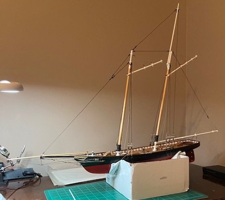
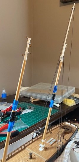
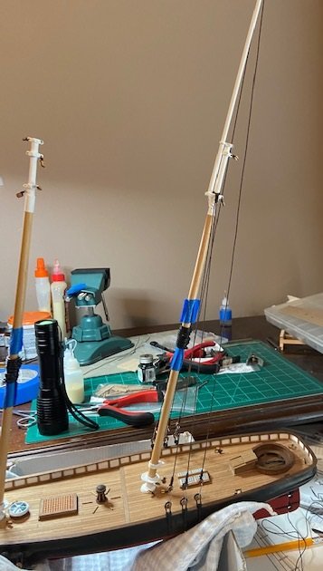
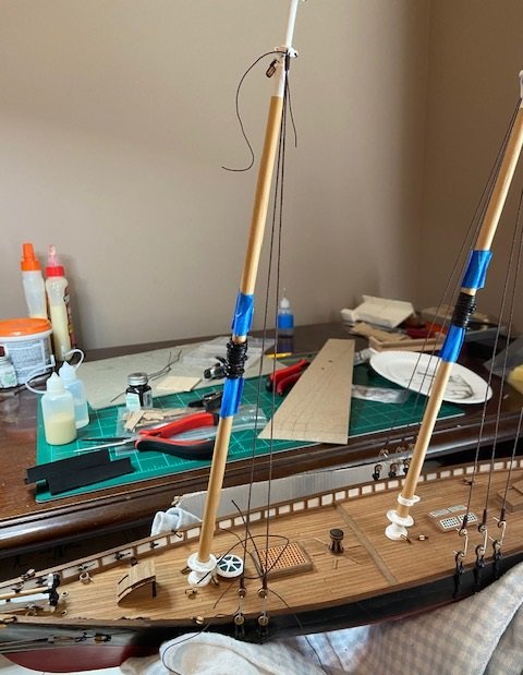
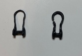
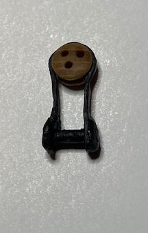
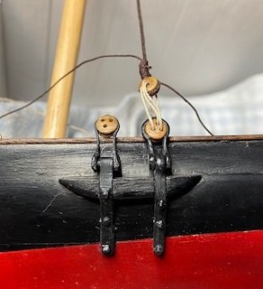
It’s been about 2 weeks since my last post, and it’s been a frustrating 2 weeks as I’ve worked on the shrouds. This kit has 10 shrouds, 4 on the forward mast and 6 on the aft mast. My rigging seemed to go well, and I was able to get all shrouds installed, but not without issues. This sequence of photos shows the progression. My biggest concern as I approached it was to get the rope to the correct length so that each would have adequate tension. I’ve tried to follow the plans for the correct length and the correct position of the deadeyes, and it seemed to me that each needed to have as much tension as each component could support. I realize now that this is not correct and I placed too much tension on the shrouds, and as I worked from one to the other the chain plates were being stressed. The white metal is soft of course, and eventually the tension would pull various deadeyes loose from the chain plates. After this happened several times, the chain plate metal fatigued and wouldn’t hold the deadeye, and eventually broke. I had to remake 2 more of the chain plates. Also, another metal piece that failed was one of the brackets around a deadeye. This was another piece that I had to remake as well, and all of this remake work was time consuming. This photo is the replacement deadeye bracket and chain plate. It’s not an exact match, but for the sake of time and in wanting to move forward with my build I think I will live with the way it looks. I also realized that I had made the shrouds for the front mast too short to try make have more tension, and that of course it what caused the chain plate metal to fail. I decided to remove the front mast shroud rope and replace it with rope that had a more appropriate length, and would still have the appearance of tension without stressing the other pieces. I hope to have finished the shrouds by next post. It seems every corner I turn there’s new lessons to learn.

-
GrandpaPhil, very good advise to use a dowel rod. That did not occur to me. I'll file that away for future reference. Thanks!