Doug McKenzie
-
Posts
223 -
Joined
-
Last visited
Content Type
Profiles
Forums
Gallery
Events
Everything posted by Doug McKenzie
-
Thanks Cathead / Eric (I don't know the etiquette for using which name) I've ordered a copy of Bate's book and that should be very useful! Doug
-
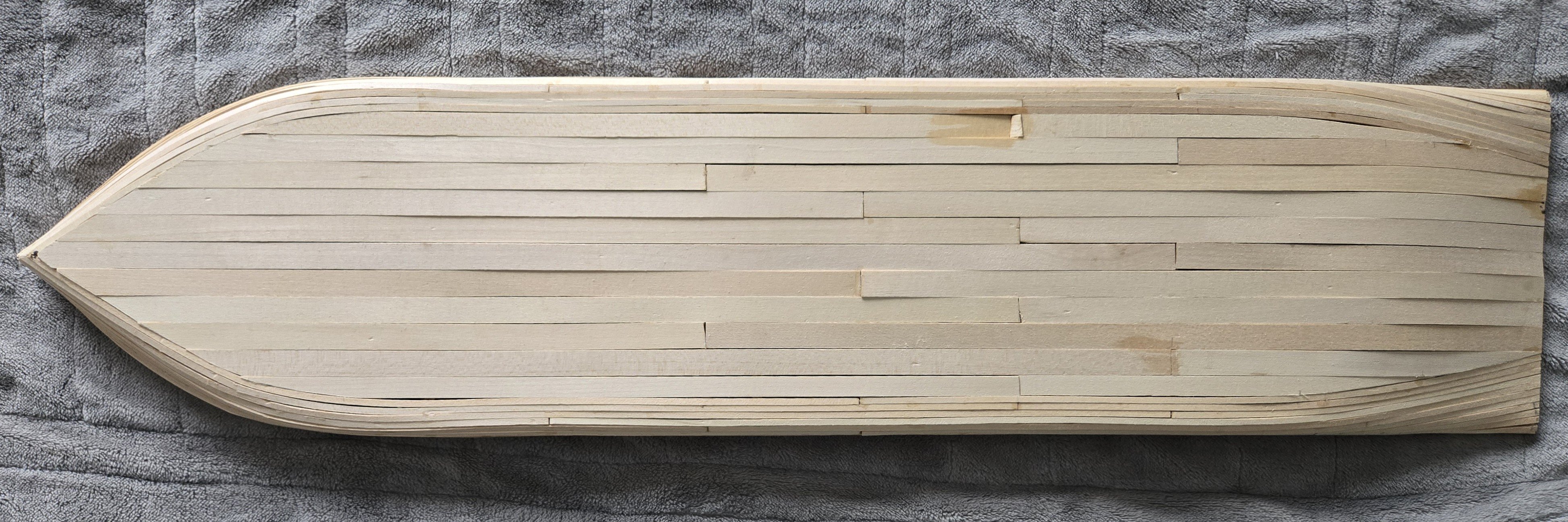
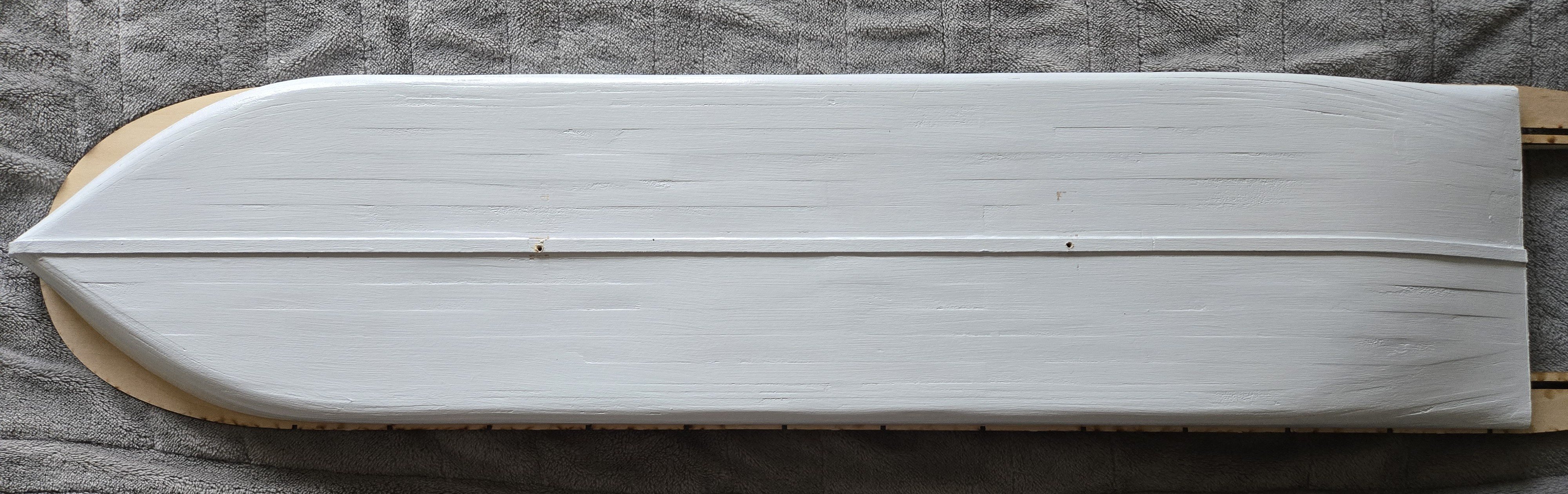
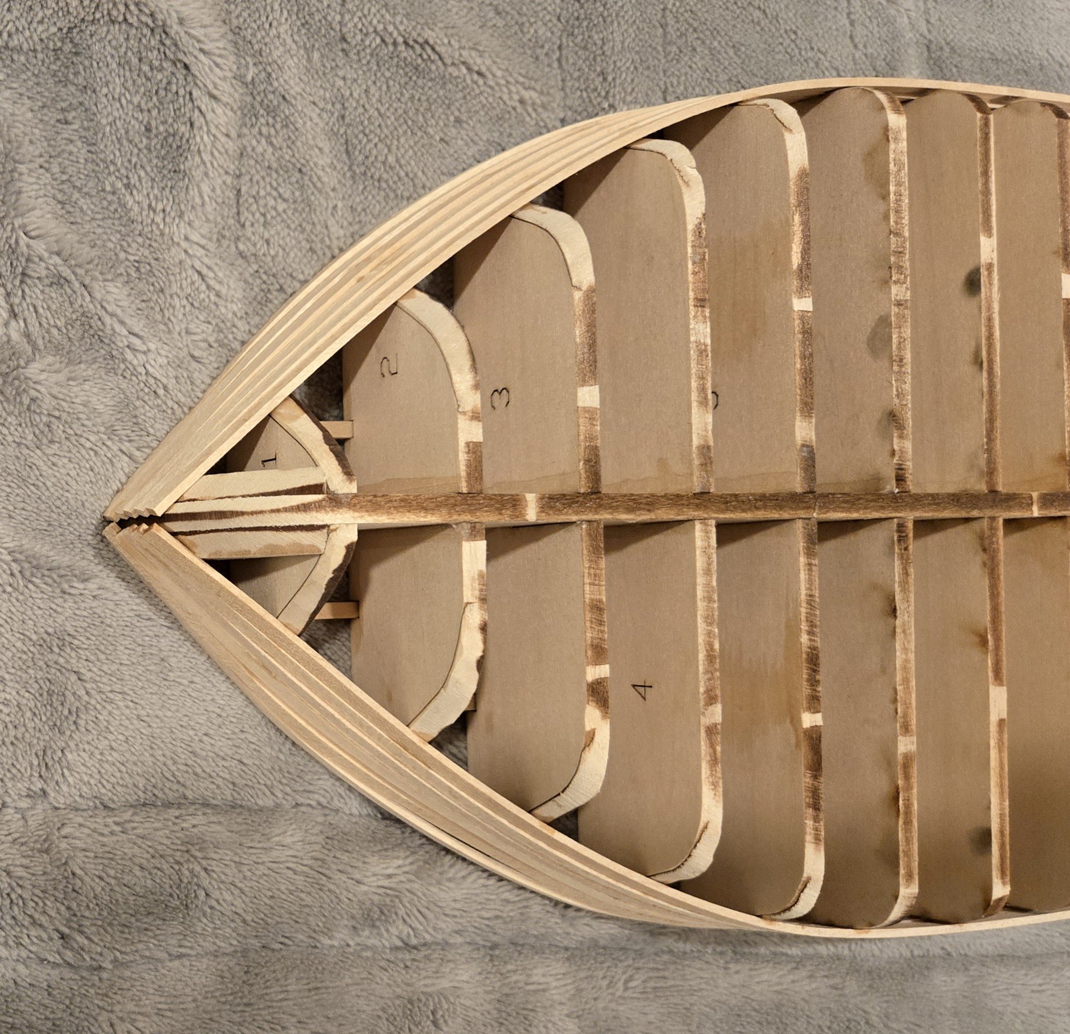
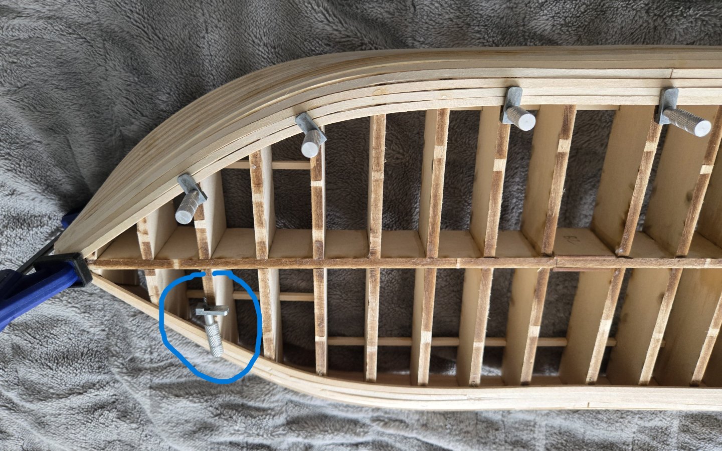
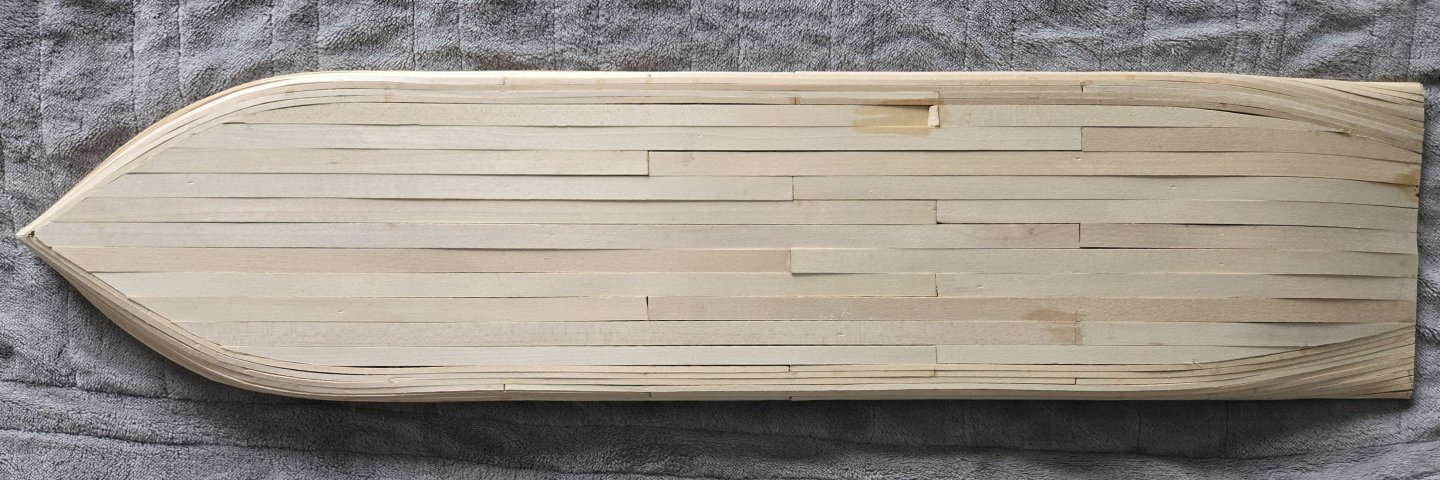
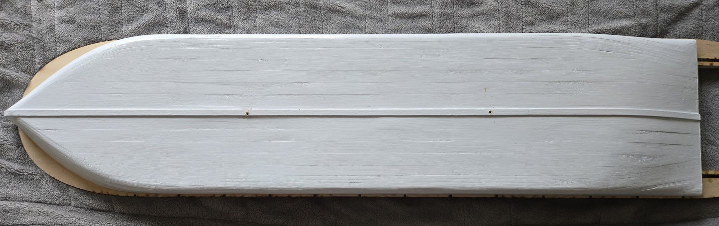
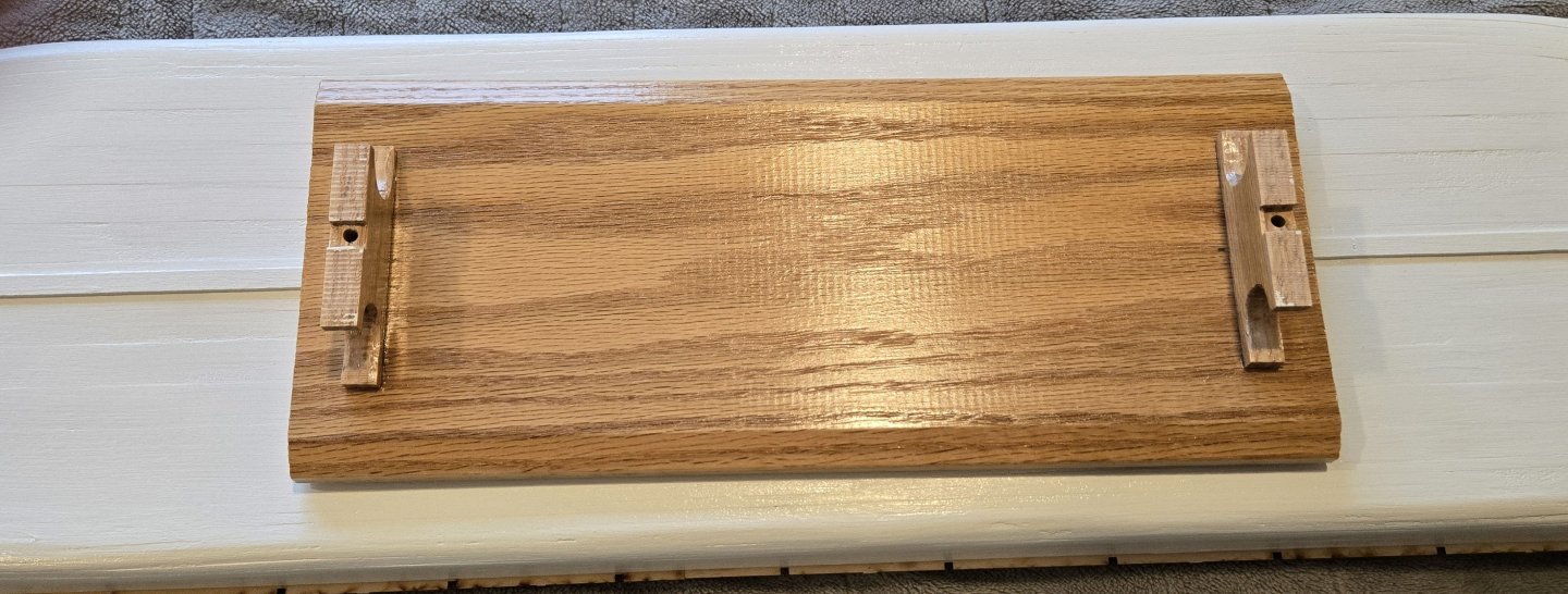
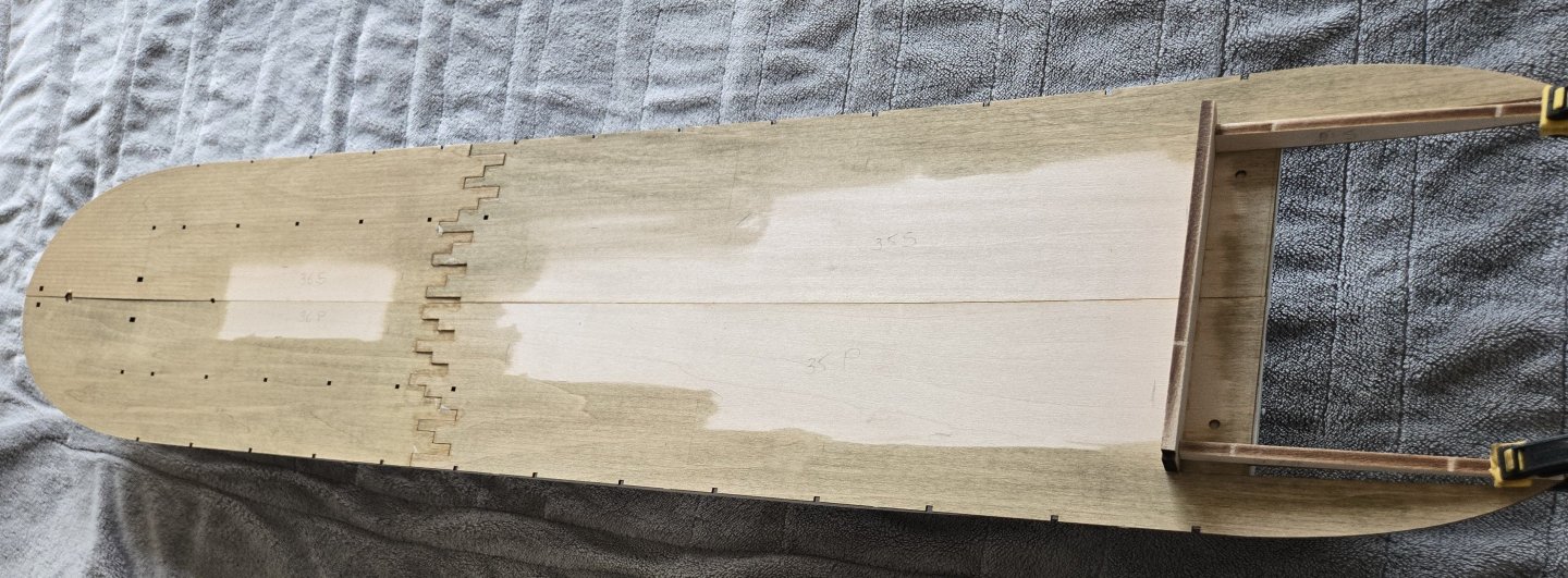
Before I describe the work, I want to thank Cathead for telling me about Kurt's instructions for Chaperon. I haven't received them yet but I'm told that they have been shipped. Pic 1 shows the 7 bilge planks at the bow. I don't bother showing them at the stern because there is so little bending, twisting or edge setting. At the bow, however, the edge setting is significant which is pretty clearly seen. The clamps I'm using are from Micro Mark and the only comment I'll make is that drilling a tiny pilot hole before trying to screw in the screw makes things a LOT easier. In the blue circle is the two part clamp (not in use) can be seen. Pic 2 is of the first half of the bottom planks. I only include this because it looks pretty cool. The planks are 1/2" wide (24" full scale!) I use the same 3 bulkhead spacings for butt joints in adjacent planks but now only require 2 planks between butt joints on the same bulkhead. Pic 3 is of all the bottom planks. I sanded most of the irregularities with a Micro Mark Micro Lux miniature belt sander. I filled the remaining irregularities with Minwax stainable wood filler. Sanded again and did the final filling with joint compound. The wood filler had a very tiny sand-like texture which is why I switched to the completely smooth spackle. I didn't use the spackle at first because somewhere along the line I heard that bare wood could suck the water out of the spackle making it weaker and it's already not all that strong. I have to apologize for Pic 4 because I have broken a cardinal rule of traditional ship modelling which is that we don't use gloss paint. I couldn't resist for 3 reasons: 1-- I like gloss finishes, 2-- The vast majority of the hull surface would never be seen anyway (70%) and 3-- I wanted the planking to be evident which it is at the bow. I won't bother to apologize for the poor filling and sanding job because the worst is on the bottom and the sides are a bit better. I'm not a perfectionist at all. BTW you may notice the deck has already been installed. I forgot to take a picture of the painted hull and so had to remove it from its stand to make this record complete. Pic 5 is the stand. I used the template for the stand uprights in the kit. The base is from an old door sill. Pic 6 shows the deck stained Minwax Driftwood (specified by the instructions) and installed. I did the best I could to minimize the unevenness of the joints between the panels. If I had it over again I would have joined the bow and stern panels together before gluing them onto the hull because it would have been much easier to align them properly. I also would have waited to stain the sheets until after they were joined so I could have done a little sanding. I figure I'll wait to see how much of it stays visible after more stuff is added and maybe a little improvement will be possible. At this point I want to mention that the instructions provide little in the way of riverboat terminology. Therefore I decided to try to learn some of the names of the parts of the boat. So for example, you can see that the 'fantail' is in process (i.e. "the overhanging extension or platform at the rear of the boat upon which the sternwheel is actually mounted"). I got this from google AI. Please note that there were very few diagrams found so I will be applying these terms without the assurance of knowing that I am doing so correctly. I believe that the beam extending aft and supporting the deck extension is called 'cylinder timber.' "These are the large horizontal beams that extend past the stern of the hull to support the weight and axle of the paddlewheel. They earned this name because the steam engines (cylinders) were traditionally mounted directly onto them." This is a good example of the value of the pursuit of terminology because we also learn that the weight of the engines is used to counterbalance the weight of the paddlewheel.
-
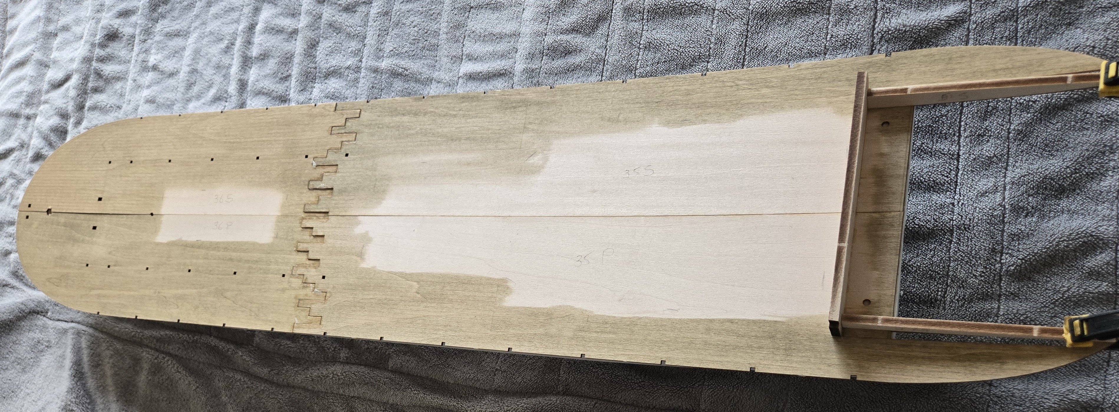
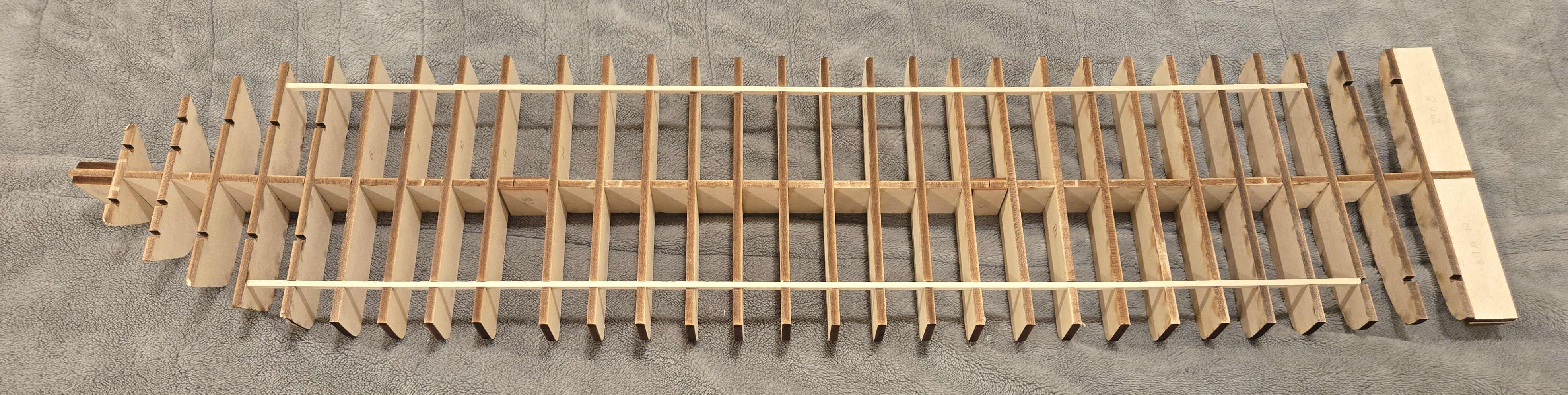
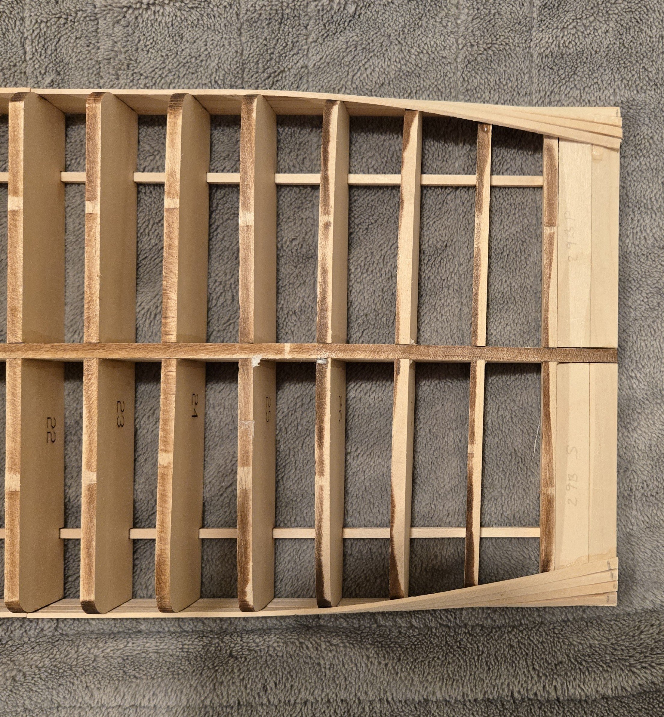
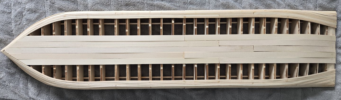
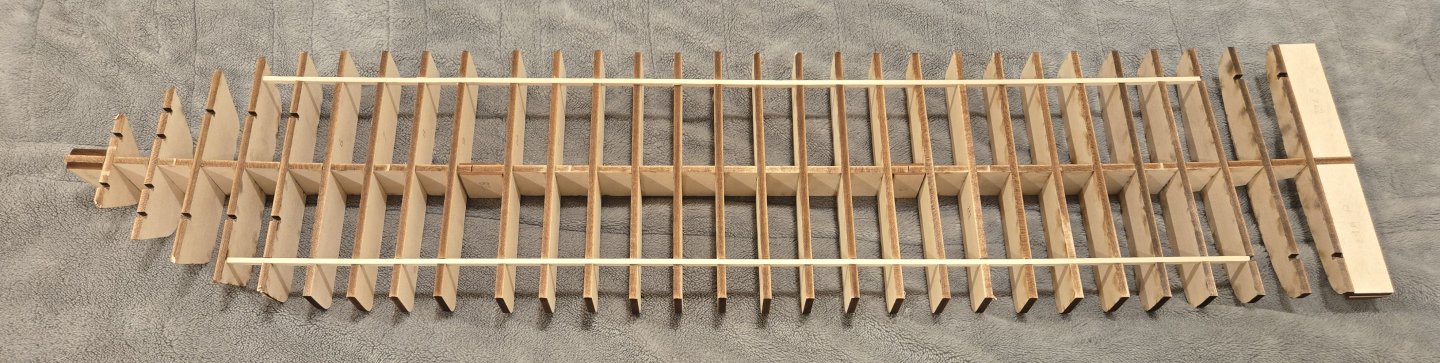
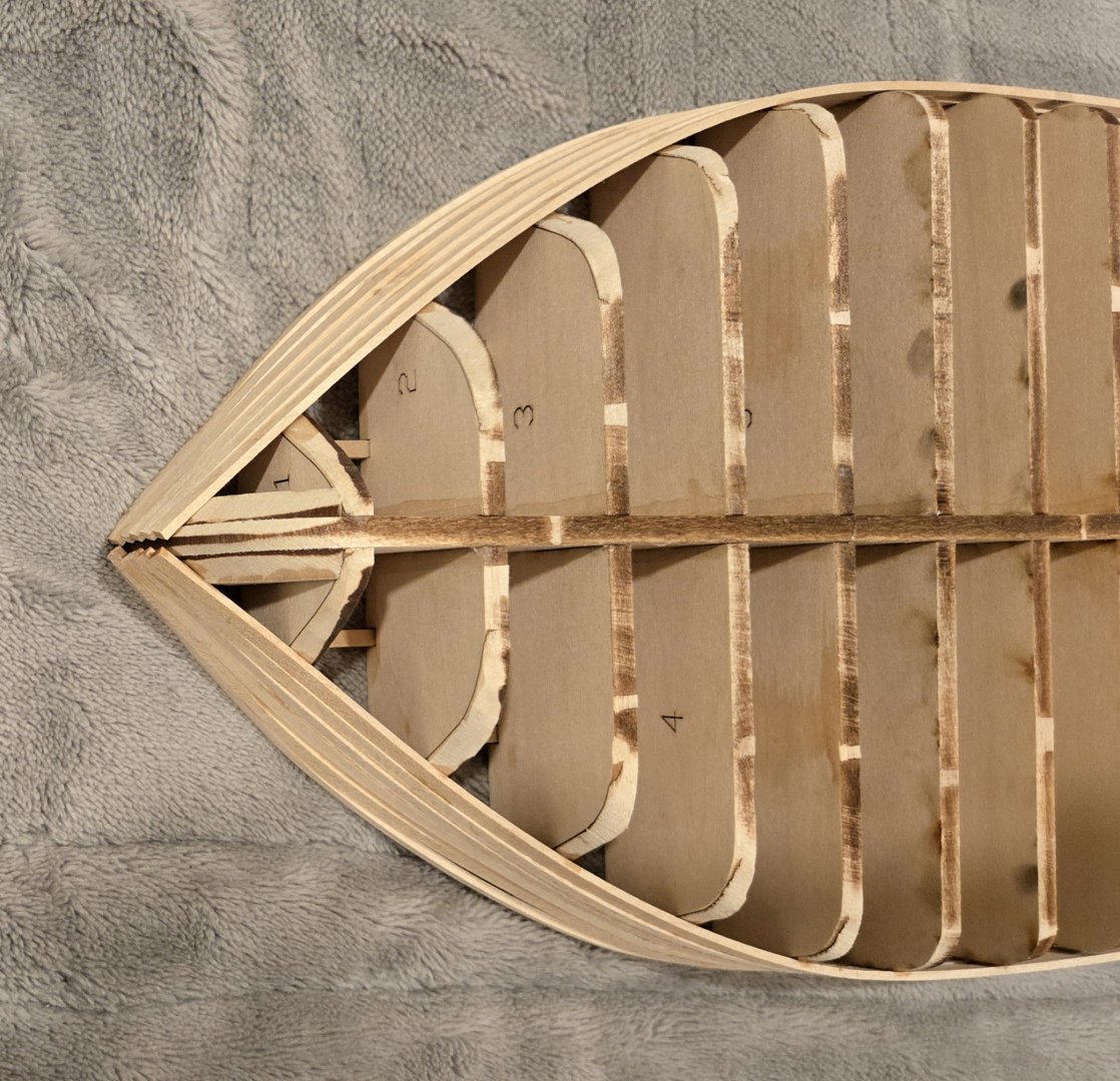
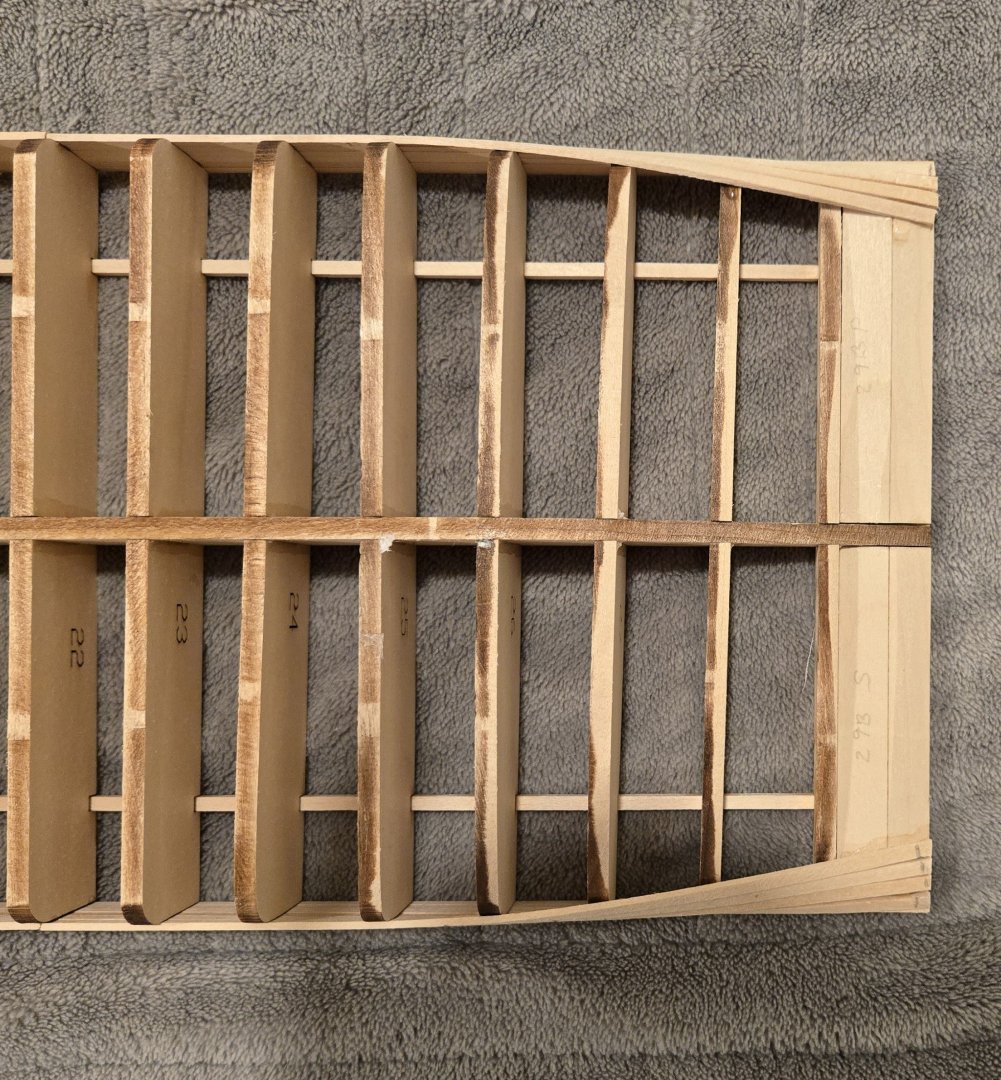
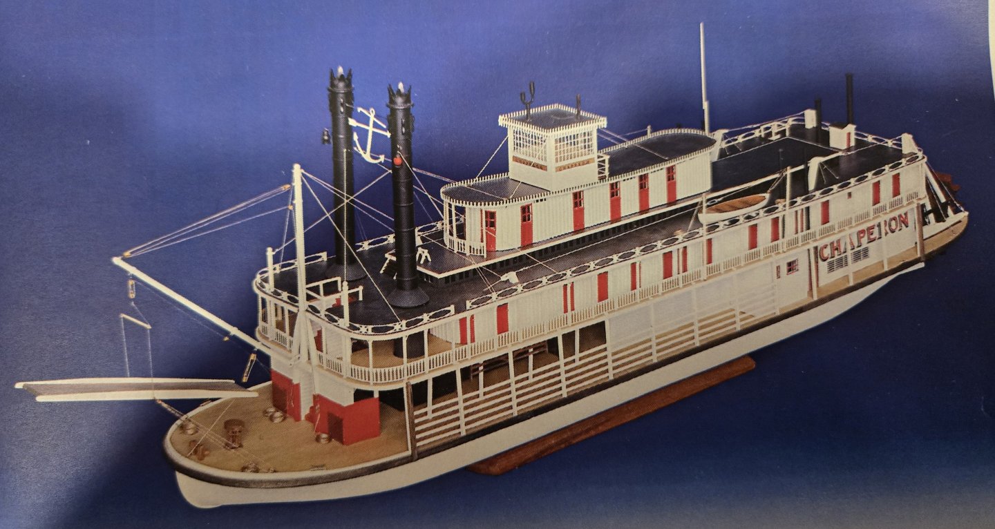
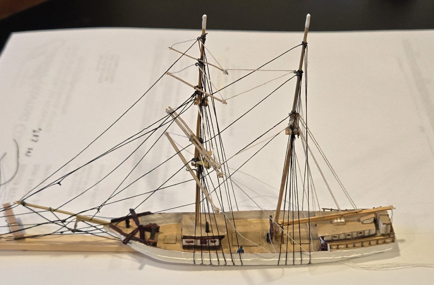
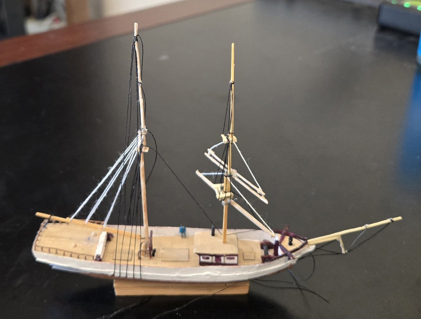
Having almost finished Leon in a bottle, I decided to get started on Chaperon (1884 Steamer aka Riverboat). A 1:48 model by Model Shipways. I knew I wanted to try a riverboat so I 'researched' and found this kit. Someone said it was the best kit in terms of being an accurate reproduction of an actual riverboat. I couldn't remember who said that, so I asked google. This was the response. "While there is no single individual credited with this definitive claim, the Model Shipways Chaperon is widely cited by experienced modelers on major ship modeling forums as the best and most accurate riverboat kit available." Easiest research I've ever done! Here's a picture, Pic 1, of the completed model that Model Shipways supplies. This will be my first "non-sail powered ship" model (except for when I was under 10). It will also be my first non-operating ship model that will be fully painted. Pic 2 shows the keel, bulkheads and 2 stringers. The keel and stringers are 3/16" and the slots are cut very accurately so the bulkheads lie firmly perpendicular to the keel quite well. The 5 forward bulkheads have bevel lines marked so that the frames can be easily beveled before mounting on the keel. Similarly, at the stern the bottom surface of the counter is marked for pre-mounting beveling. Both of these things makes fairing the bulkheads and the counter before planking a lot easier than with many models. Pic 3 and 4 shows the side planking complete - Pic 3 is the bow and Pic 4 is the stern.. The planks are 1/16" x 1//8" and are easy to work with. The kit recommends pre-bending the planks which I did only at the stern. I consider the side planks to consist of the sheer plank and the next 5 down. The first two needed no pre-twisting at the stern but the 3rd plank needed to be twisted 90 degrees over about 2". Each additional plank was twisted over a length longer by the spacing of the bulkheads. So the first was the tightest and they get progressively less tight as you proceed down although all need a full 90 degree twist. . I didn't pre-bend at the bow at all, I just glued a few bulkheads at a time. btw I use extra thick CA glue for planking. I didn't follow normal practice of setting each plank on both port and starboard. The bullhead/keel construction is so strong that I completed 3 strakes on one side and then did the corresponding 3 strakes on the opposite side. I left 3 bulkhead spaces between butt joints in adjacent planks. I left 4 planks between 2 butt joints on the same bulkhead. None of this matters much on such a strong structure but it felt good to follow a sort of normal procedure. The 7 bilge strakes will come next.
-
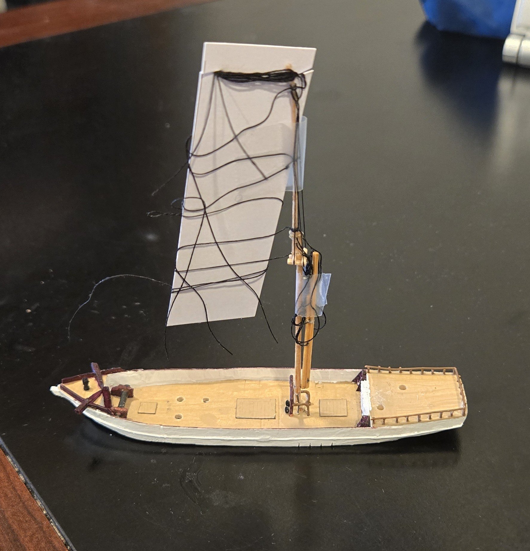
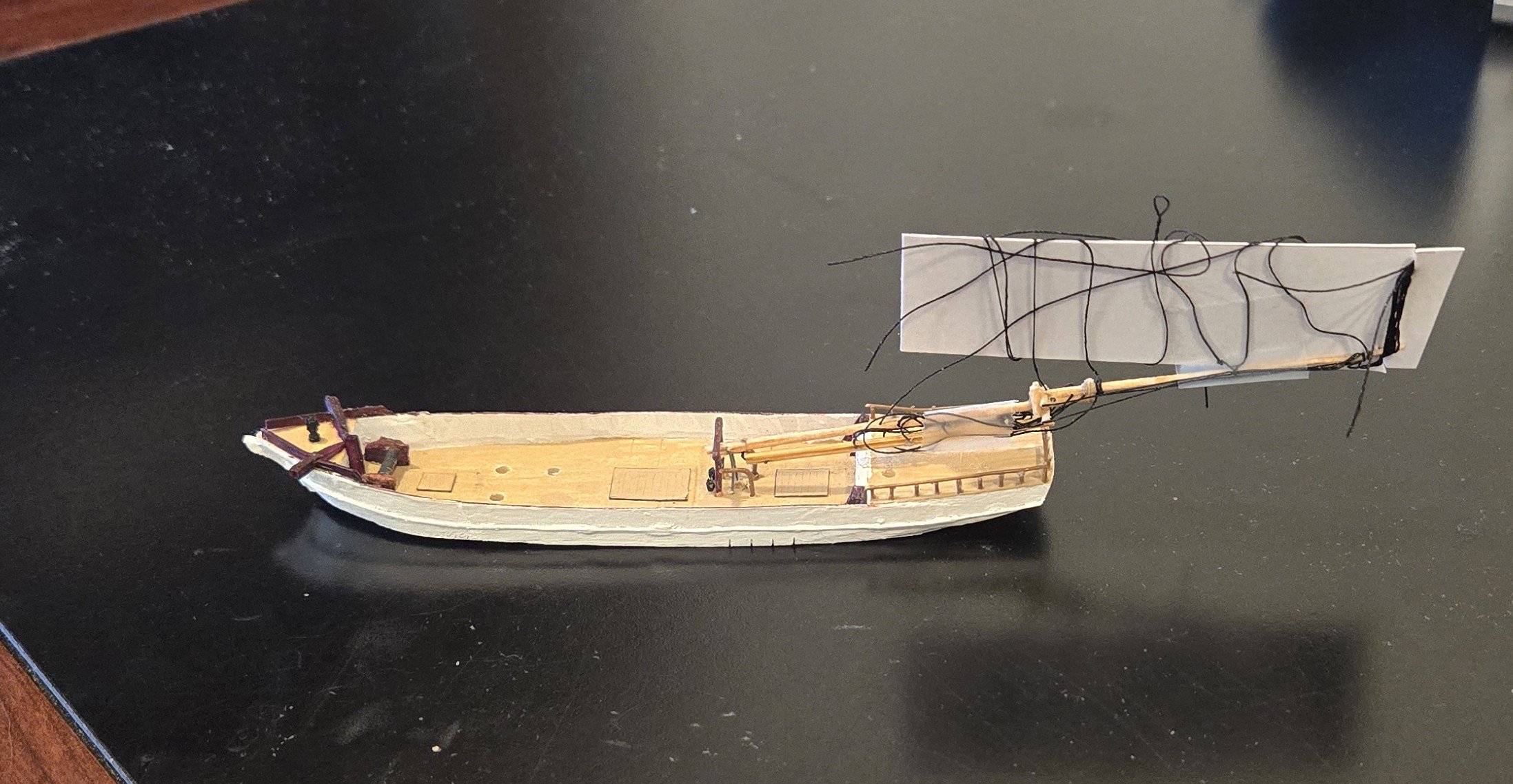
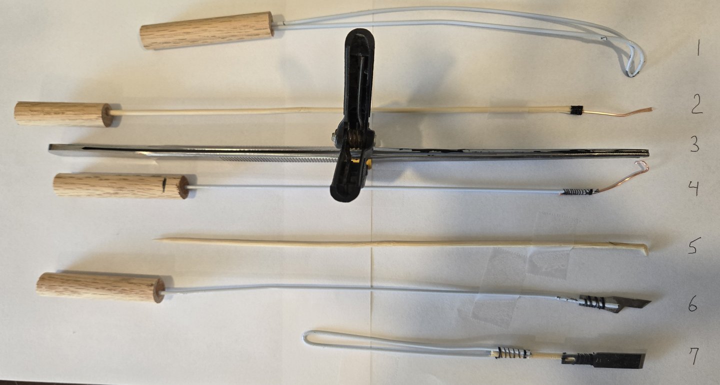
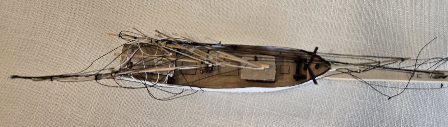
Just a few items left. All 4 remaining forestays have been glued and clipped, The main cap-stay and the main topgallant stay have been glued and clipped, The upper topsail, the topgallant and the royal braces have been fitted. A number of repairs are needed to finish the job, however. Before tackling the repairs, we'll mention that the braces for the 3 upper yards lead back to the mainmast, unlike the lower two yards that went to the bulwarks. To make them work when putting the ship into the bottle they were rigged differently than for the lower 2 yards. Thread was tied to the port yardarms, led back to a thwartship hole in the mainmast and then left hanging. Fitting these braces involved gently bringing the port brace taut and gluing the starboard brace to the starboard yardarm and then trimming the leftovers off. Keeping the braces taut was marginally successful. After identifying the repairs need, we'll talk about the tools used on this project. Starting from the tip of the jibboom the needed repairs are: 1-- Tufts from the fore royal stay & the jib stay. 2-- Remove the copper wire ring. 3-- A tuft from the mainstay. 4-- A small tuft from the main cap-stay. 5-- The foot of the main topgallant stay needs to be reattached. There are a number of problems with the mainmast because it did not come to the proper rake that would have tightened up the shrouds and backstay. 6-- Tighten up starboard shrouds #2 and #3. 7-- Tighten up the starboard backstay. 8-- Reattach the port backstay. 9-- Tighten up the peak halyards. 10-- Remove a few drops of glue on the inner surface of the bottle. There are no guarantees that I will be able to effect these repairs but I'm going to try. #1 helped press the lower hull onto the ocean when it was glued in place. Then again used to press the upper hull down onto the lower hull when it was glued. I couldn't apply enough pressure to make that joint close though. #2 helped to push spars and rigging into place. There is a small groove filed out of the square tip. #3 long tweezers with a clamp that allowed hands free gripping of rigging. #4 for pulling spars and rigging into place. #5 for applying glue. I only used maximum viscosity CA glue with this tool so it would not drip. That did not stop me, however, from leaving a few glue drops on the inside of the bottle. #6 a smallish cutter. #7 a larger cutter - both used to cut threads. I should also point out that the bottle introduces more distortion than I expected. In my final picture of the ship I will try to find an angle that minimizes the distortion. In any event, I was planning to tackle the repairs before posting but I seem to have another attack of lack-of-confidence and as a result I seem reluctant to actually tackle the repairs. I do not know how long this reluctance will last so I'm going to post now. BTW the lack-of-confidence has to do with a fear of making a mistake that can't be fixed.

-
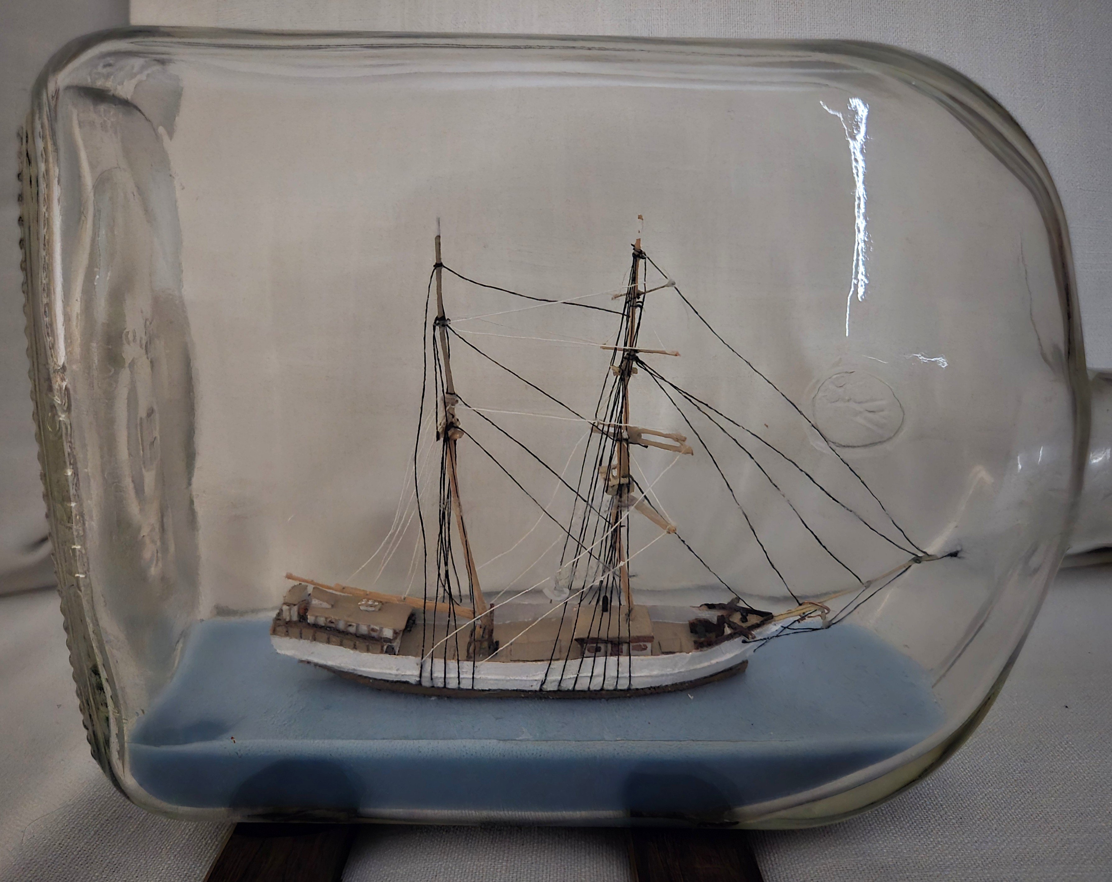
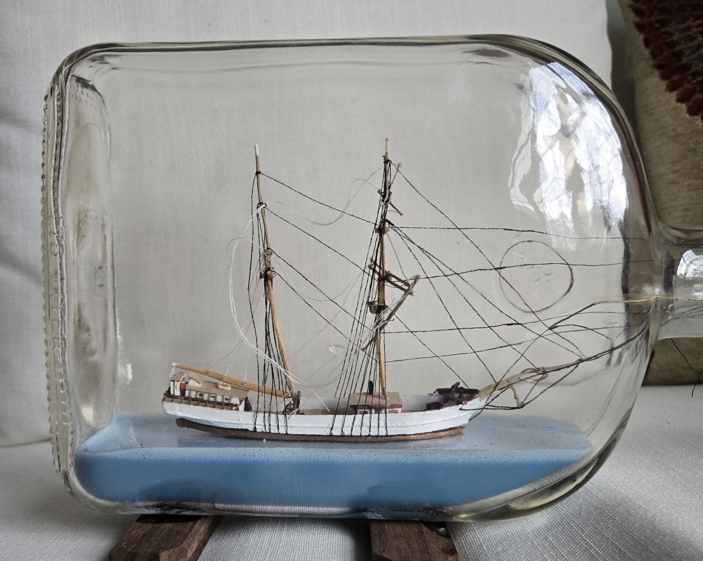
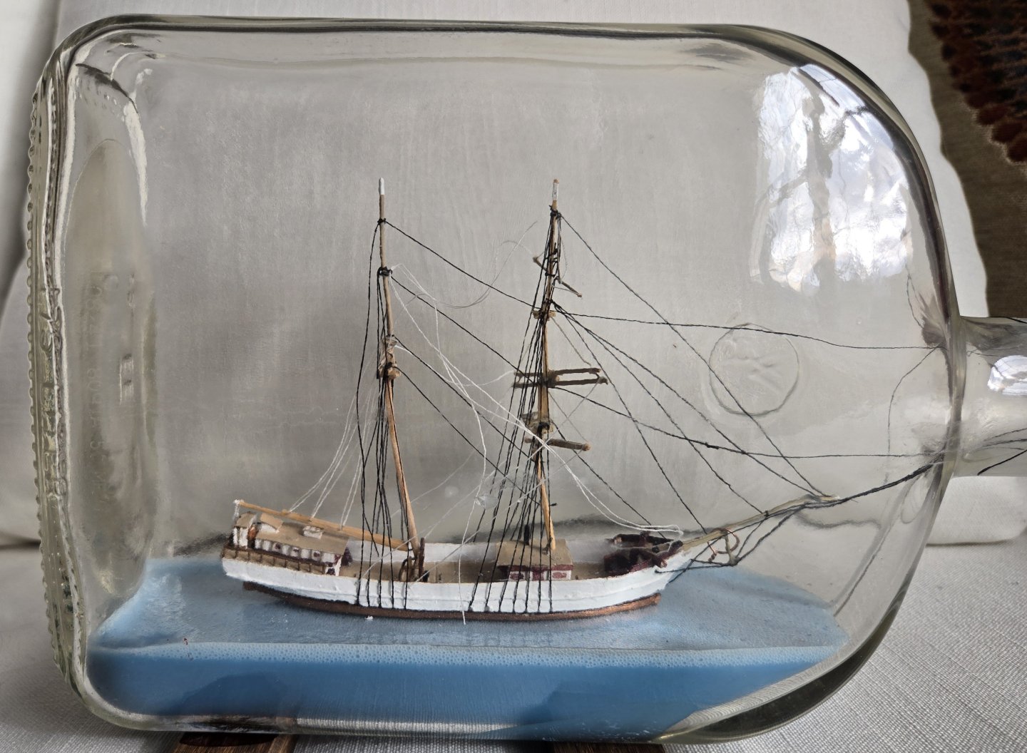
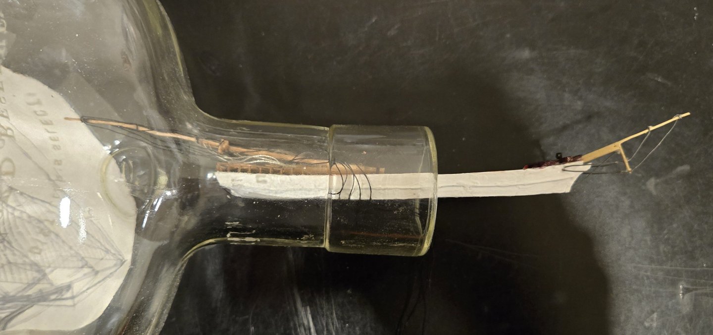
After about a 3 month hiatus due to flagging confidence that I could successfully do the the delicate work coming up properly, we are ready to continue. Pic 1 shows Leon glued in the bottle with all the extensions of the stays coming out the neck. The work of gluing the hull down was clumsy and not well done but at least it's finished. Now we are ready for the final adjustments of the stays and braces. I usually reduce the size of these pictures but I think the larger size is useful to see the rigging more clearly. I had a plan for how to proceed but that plan changed at every step. The first step was to tighten the forestay, put a drop of glue where it entered the anchor deck and then cut it off where it left the stemhead. This worked beautifully. I had planned to continue with the fore topmast stay but realized that structurally it made more sense to do both the mainstay and the main cap-stay because they end at the lower foremast which was now stabilized by the forestay. There was a problem, however, because the 4th main port shroud had apparently been compromised when the upper hull was glued to the lower hull so the mainmast could not rise to its proper position. The only remedy I could think of was to cut that shroud at the waterline and hope I could glue it back in place when the rest of the rigging was done. Having cut this shroud, I fitted the mainstay. I unskillfully cut that stay where it left the lower foremast leaving a tuft of thread about 1/16" long which hopefully I'll figure out a way of removing later. Then I fitted the main cap-stay and cut that off pretty cleanly. Now I figured to fit the main topmast stay since it ends at the lower foremast cap and thus is also stabilized by the forestay. Unfortunately, the lower topsail yard is also attached to the lower foremast cap and I was afraid that a drop of glue for the main topmast stay might immobilize the lower topsail yard. So I decided to fit the upper topsail yard (which is rigidly attached to the lower topsail yard but is a little above the lower foremast cap) before working on the main topmast stay. I also figured to fix the lower yard. Since I was fixing all 3 lower yards it seemed reasonable to fit their braces also. At this point, I figured another photo, Pic 2, might be interesting. The easily seen differences between these two photos ae 1-- The missing 2 extensions of the 2 lower mainstays leading out of the neck and 2-- The correct orientation of the foreyard. The braces for the lower 2 yards can also be seen but being white they are not very obvious. Before putting the ship in the bottle, the braces for the foresail and the lower topsail were taken from one yardarm, down to a hole in the bulwark, across the deck in a loose bight to a hole in the opposite bulwark and up to the opposite yardarm. Now in the bottle, after the yard was glued to the mast, a hook was introduced through the neck of the bottle, back to the bight which was then gently pulled taut. The brace threads were glued to the holes on the outside of the bulwark and then cutoff on the inside of the bulwark. Also visible is a ring of copper wire around the martingale - this is a remnant from the clamp that allowed the ship to be inserted in the bottle. This will be removed later after all the threads are out of the neck of the bottle. I'll talk about the tools used for these operations later.
-
Alan, thanks very much for the vote of confidence but let's not ignore the fact that the lower foremast broke on my watch.
-
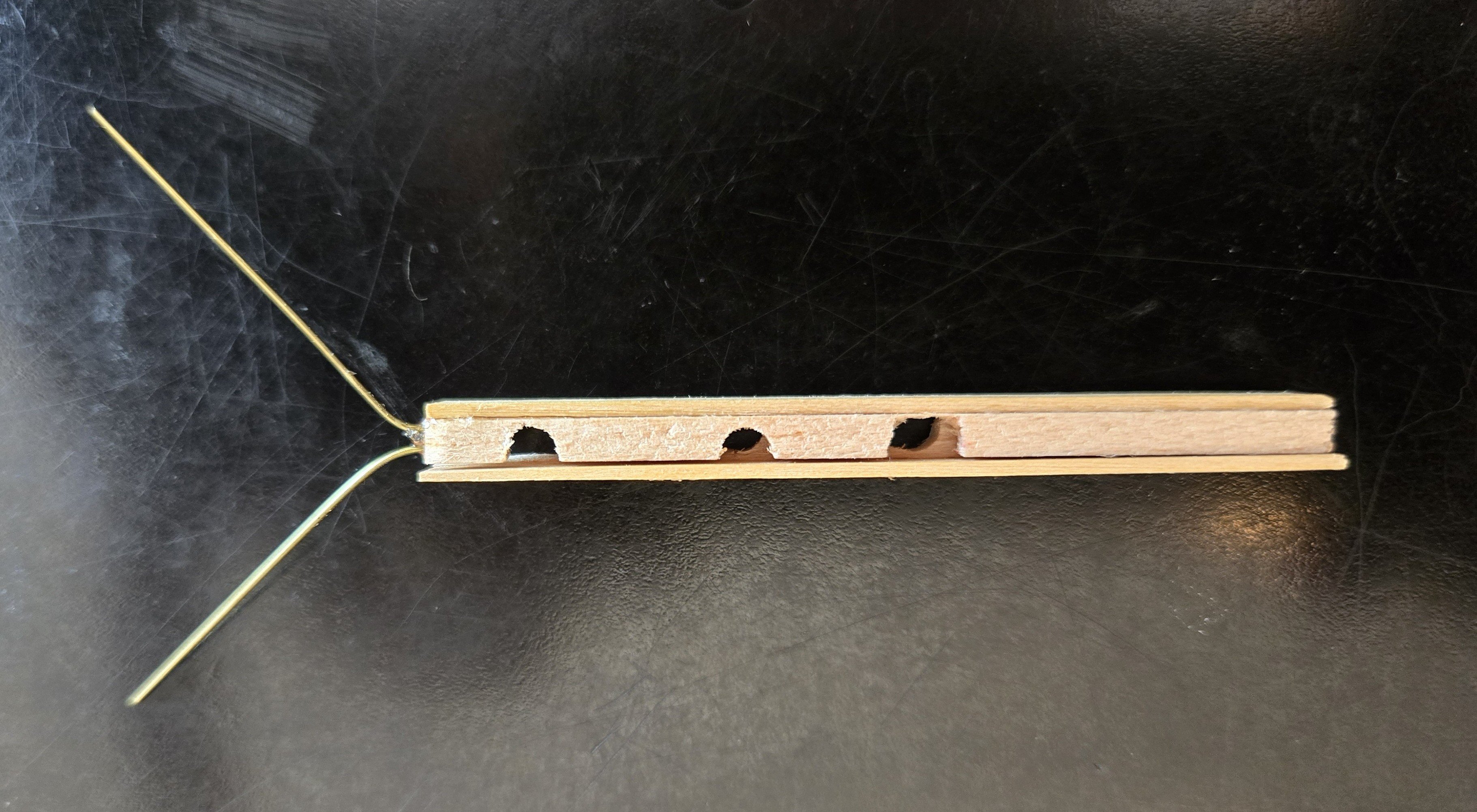
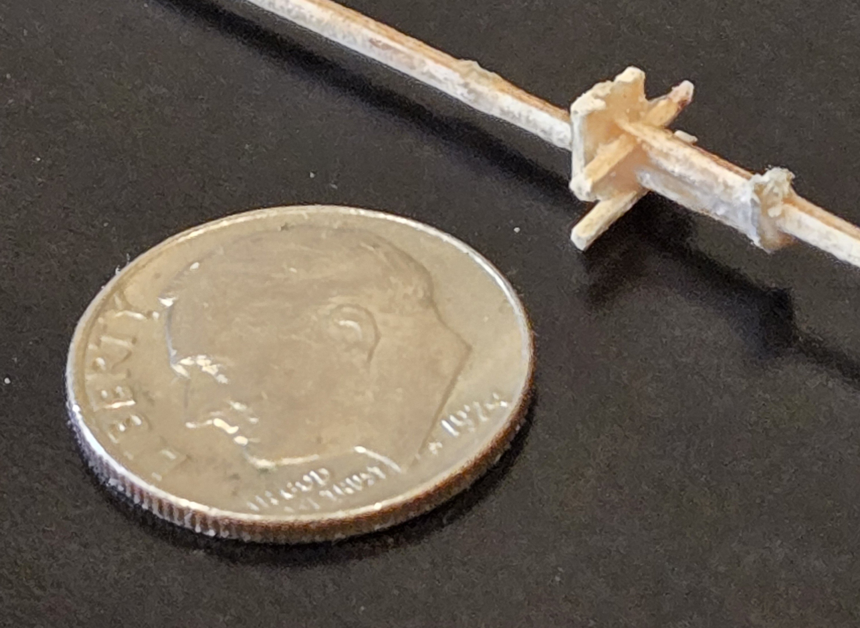
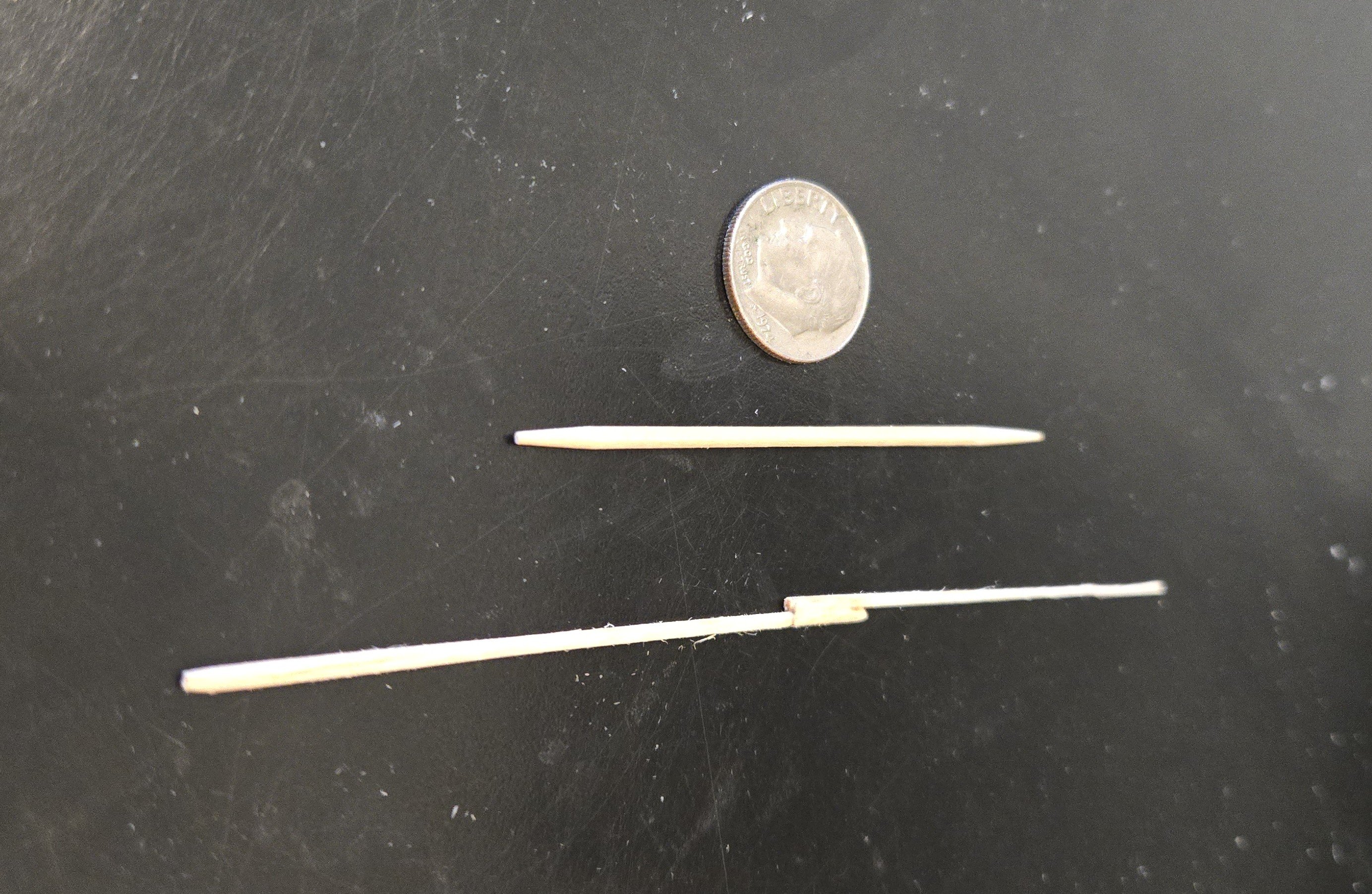
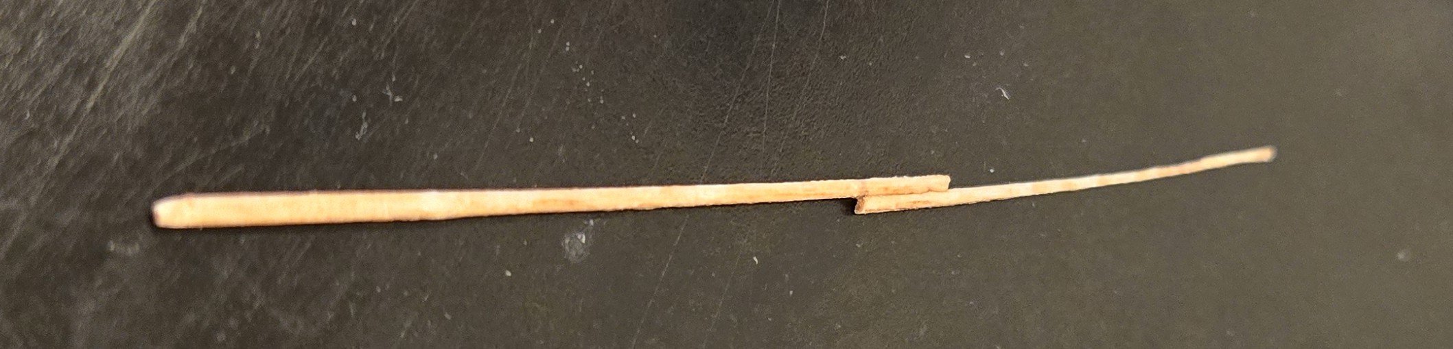
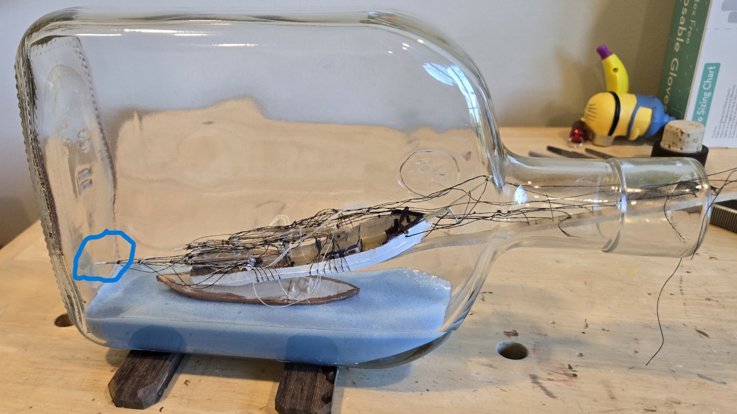
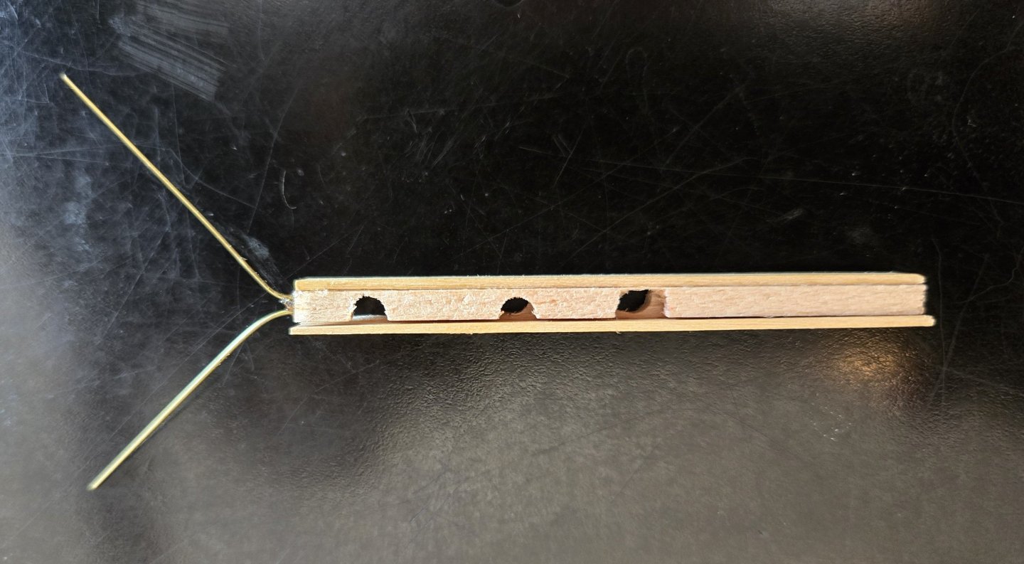
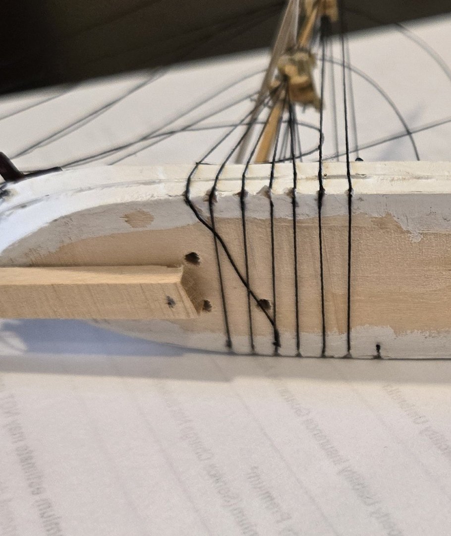
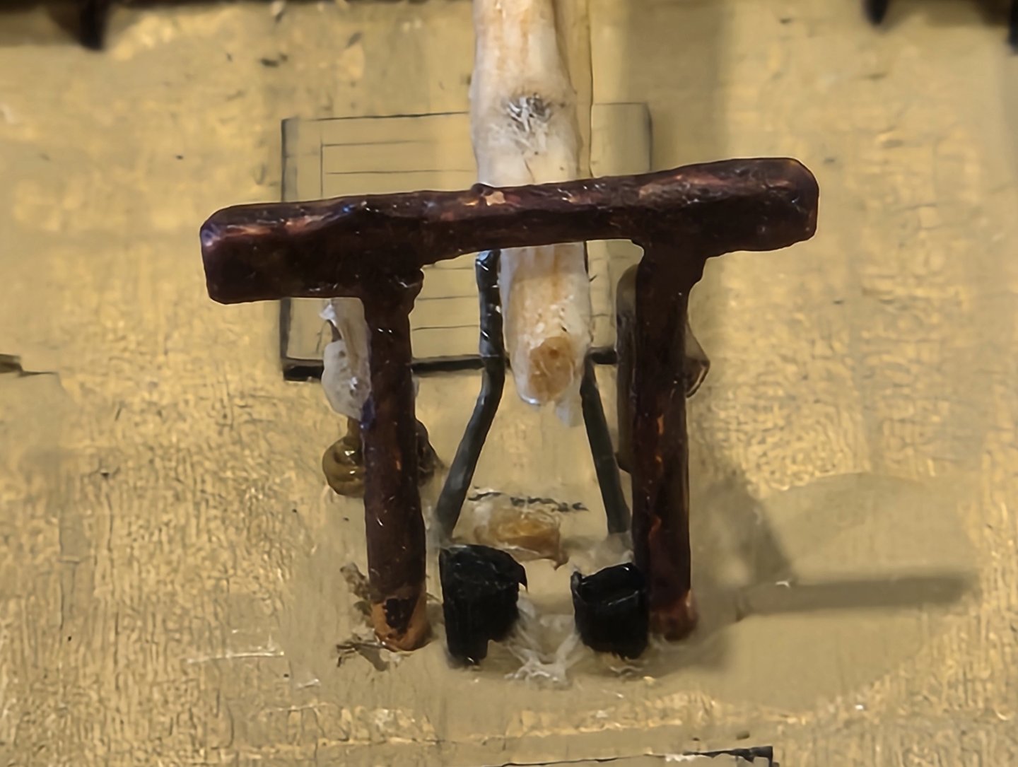
The easy part of inserting and gluing the hull was inserting and gluing the below water line part of the hull to the ocean. Somewhere I read that CA glue should not be used on the epoxy resin so I used silicon glue and that seemed to work fine. You can see this piece in Pic 1 although I should have taken a separate picture to show the 5 dowel heads protruding up to make positioning the upper part of the hull accurate and easy. I cannot believe that I wrote the line "Leon is ready so it just remains to fold her up, insert her into the bottle and then raise her up again!". Major issues have arisen in "insert her into the bottle". 2 issues in particular. The first is that Leon cannot be placed on the lower part of the hull without raising the main mast somewhat. The reason is that the mainmast hits the bottom of the bottle before the hull is in the correct position. Pic 1 shows this in the blue "circle". This might not seem to be a serious problem. The only way I can express it is to say that to keep the masts up I need to pull on one of the stays. To position the hull properly for gluing down I have to push the hull into the bottle. This requires that there be something firm to support both movements at the same time. You can see in the picture that the firm thing is the stick that organizes all the rigging. Unfortunately this is screwed to the bottom of the hull and has to be seperated from the hull before the hull can be inserted and glued. Once seperated there is nothing firm any more. How to design a tool that will hold the hull firmly and then be removable once the glue cures. The tool that I came up with piggybacks on the fortuitus use of a metal rod for the jibboom documented earlier. This provides a firm anchor for the tool which has two parts, one clamped on the left side of the jibboom and the other on the rightside. Pic 2 shows the two parts together (without the jibboom and Pic 3 shows the two parts separated. T The slots that have been filed permit the stays that pass through the jibboom to be adjusted when the clamp is on. The two rods project under the catheads to provide more firmness. Pic 4 shows several things. First, it shows the 'tool' clamped around the bowsprit/jibboom. Second, it shows the stick that organises the 4 main stays and the 5 fore stays. This stick pivots around the tool to facilite getting the boat into the bottle. Third, it show the the ship hanging upside down to make mending the lower foremast easier. (I don't remember if I mentioned that the lower foremast broke just below the mast band supporting the forecourse truss during these machinations.) Hanging it upside down greatly facilitates ensuring the right alignment as the glue cures. The pink clamp pulls down on the upper masts also to facilitate the alignment. Having the stays all organized also helps this mending by keeping all of the rigging away from the mend point. The only remaining problem that I am aware of now is that mending the mast will most likely also glue the fore yard to the mast which is not OK. I'm thinking of cutting the fore yard truss (wire) and replacing it with thread after the mend is complete. The upper yards mostly use thread also. o Wish me luck on the mend and the next post should feature gluing the upper part of the hull to the lower part (already glued to the ocean).


-
Well, a couple of days has turned into 2 months but whose counting. At least the ocean is done now! My friend Marty and I managed to get the epoxy resin into the bottle without making too much of a mess and the neck of the bottle is quite clean. The basic technique used I saw in a YouTube video about a year ago but I can not find it again so I can not properly give credit other than say thank you. We used the MAX CLR products of The Epoxy Experts of Canada. A 45 minute phone conversation with them was instrumental in the successful creation of the ocean. The first problem was that epoxy normally generates an enormous amount of heat as it cures. When thin films are involved there is no problem as the heat can dissipate easily but in this application a very thick glob of epoxy is curing and the heat could easily damage the bottle. To prevent this, equal parts (by weight) of a Calcium Carbonate Epoxy Filler is mixed with the resin. This filler conducts heat apparently and solves the problem. After mixing these two components we mixed in the hardner (1 part by weight of hardner to 2 parts of resin or 1 part of hardner to 4 parts of resin + filler). All this mixing, by the way, was done with little plastic stirrers driven by an electric drill. Lastly, the blue dye is mixed in. We had about 750 grams of epoxy and we used less than 1 drop of dye to acheive the color in the photo. We broke off the tip of a toothpick and stuck the blunt end into the bottle of dye so that about 3/16" of the toothpick was covered in dye. That was enough to acheive the color in the photo. One alert here- when mixing the dye into the epoxy, it took almost 30 seconds before the epoxy had any coloring at all. The first time I tried this, I thought I was going to have to add more dye - If I had, the color would have been much too dark. Now to getting the epoxy into the bottle. The tools used, in order of use, are 1) the red funnel (the big open part of the funnel is not shown - it screws in to the long narrow part shown), 2) the clear plastic tubing 7/8" ID, 3) the plunger made out of wooden dowels and lastly 4) a strip of aluminum foil bent around the plastic tubing that fits into the neck of the bottle. 6 of these strips were made before starting to insert the epoxy. The aluminum foil covered about 1/2 of the circumference of the tubing. A lot of square pieces of paper towel were made available to assist in any cleanup necessary. Loading the Tubing - The plunger was pulled out of the tubing right to the end (roughly as shown in the photo). The funnel was inserted into the othe end of the tubing and the tubing was held near verticle over a garabage can. The epoxy was slowly added to the funnel and the tubing was filled up with an 1" or 2" to spare. Inserting the Tubing into the Bottle - The aluminum foil was wrapped around the tubing and the tubing extended about 1" further than the aluminum foil. The end of the tubing is wiped clean of any epoxy that may have stuck to it. The tubing was inserted into the neck of the bottle until the end of the tubing was about in the middle of the bottle. The plunger is pushed in to the tubing ejecting the epoxy out to fall to the bottom of the bottle. Extracting the Tubing from the Bottle - Problem - we don't want any dripping of the epoxy to get in the neck of the bottle. Before extracting the tubing, we push the aluminum foil forward so that it captures any drips from the tubing. Then the tubing is extracted, pulling aluminum foil with it. The aluminum foil is tossed into the garbage. It took 5 injections to bring the ocean up to the required level. The working time of the epoxy mixture is beteen 1 and 2 hours so we had no difficulty finishing the job. The surface of the ocean is actually quite flat whereas the picture makes it look concave. There are two little bubbles that are not supposed to be there. Also note that the bottle has been clamped to the workbench. This turned out to be a really good idea because with all the inserting and extraction of the tubing, there would have been problems if it had been loose. Leon is ready so it just remains to fold her up, insert her into the bottle and then raise her up again!


-
2 changes bring Leon to the point where she is ready to go into the bottle - the bottle, of course, is not yet ready for her! The first change is that the main topmast, previously made of wood and broken in three places, has been replaced by a brass rod which looks much better. The second change is that the braces have been added and require some explanation. All 5 braces are single with no tackle at all. My thinking is that the likelihood of tangling when trying to raise the mast with double or triple braces was just too great. The two lower braces run to the bulwark (not to the mainmast) and so could be installed in a loop fashion - yard arm to yard arm still allowing the two masts to be lowered and raised independently. For the three upper yards, the braces lead to eyes on the mainmast but are only fastened to the port yard arms. This allows the two mast to operate independently. Then when the masts are raised the braces can be fastened to the starboard yardarms. All 5 yards will be able to be braced appropriately and then the braces can be glued in place and the excess cordage cutoff. I've sent off for the 'equipment' needed to 'pour' the ocean so I'll be able to do that in a few days.
-
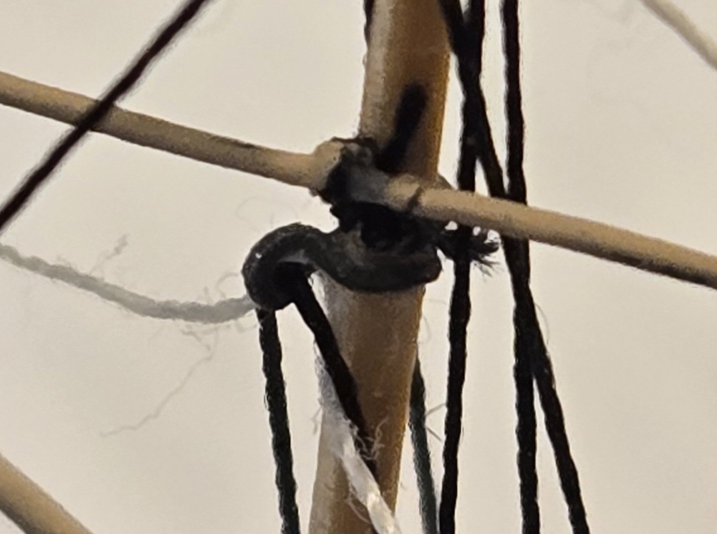
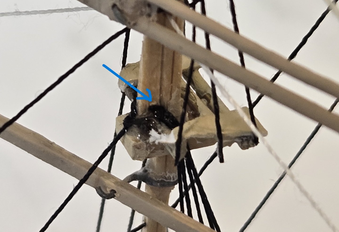
I realized that there might be interest in a few details so I took a couple of closeups: Pic 1 shows how the shrouds were handled at the foremast top. An 1.0 mm hole (blue arrow) was drilled through the heel of the fore topmast. All 5 shrouds were made from a single thread which was taken up from a notch at the waterline, through the lubber's hole of the top, through the hole in the heel of the fore topmast, back down through the opposite lubber's hole and down to a notch at the waterline, under the bottom (Pic 2) and the pattern repeated. The 2 backstays on the foremast were also included in this single thread. The problem with the backstays was that the topgallant mast and royal mast were so thin that I couldn't drill a hole that the backstays could pass through. I had the same problem with the topgallant and royal yard lifts which need to slip freely at the mast so that the yards can be canted to slip inside the bottle and then be put level again after the ship is in the bottle. Pic 3 show the little wire eye that serves to support both the lifts and the backstays. It's not accurate, of course, but it works pretty well!
-
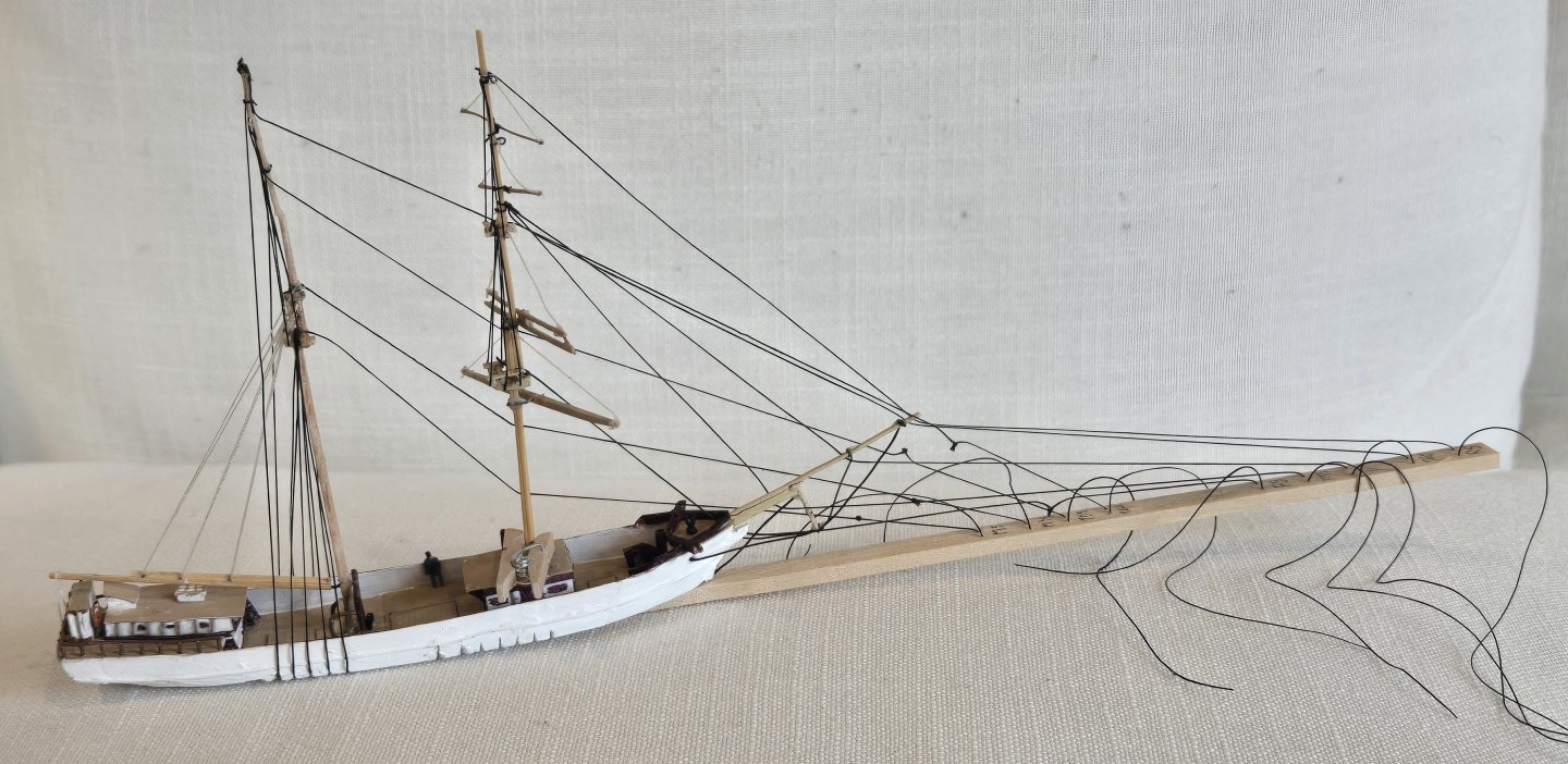
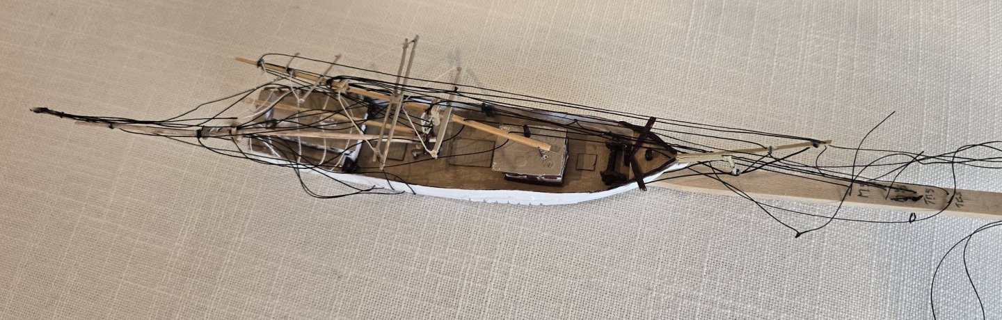
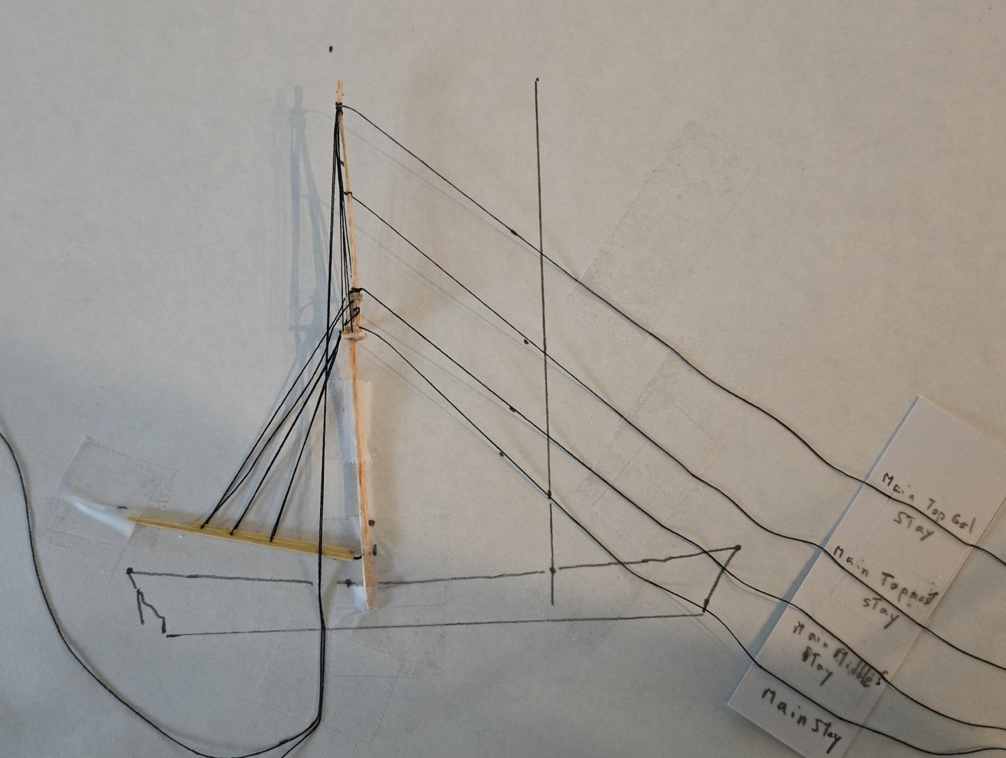
Things are getting ready for the bottle. Pic 1 shows the masts vertical with the 4 main stays and 5 fore stays rigged to the stick that keeps them neat. The main stays pass through holes in the foremast and then go to the stick. The main stays will be glued and cut off on the forward side of the foremast. The fore stays pass through 1 hole in the anchor deck and 4 holes in the jibboom and then to the stick. The fore stays will be glued and cut off on the bottom of the jibboom. I left out the fore topgallant stay. The missing rigging is the 5-on-a-side fore lower shrouds, 2-on-a- side fore backstays (there are supposed to be 4) and the 5 pairs of braces. The clamp at the foot of the foremast holds it inplace until the shrouds are installed. Pic 2 shows the masts folded aft. Pic 3 shows the yards canted to be more or less parallel the the foremast Pic 4 shows the collapsed model inserted into the neck of the bottle After the rigging is completed, it will be time to 'pour' the ocean. I'm going to be using Max EPC (Electronic Potting Compound) because it generates much less heat than other epoxies.

-
Alan, Thanks for your comments! I used Ships-in-Bottles by Don Hubbard and some youtube videos for my instruction. It is my first ship in a bottle and it is my first ship model to such a small scale. The hardest part, of course, is doing the spars and rigging to scale which is the point of the whole effort. The running rigging already in place will have to be replaced with some new stuff that I just got. Presumably you'll see that in the next post. I've also never made a point of sharing my mistakes the way I have on this blog. Those lovely thin masts have broken 5 times so far but CA glue (thick and medium) have always come to the rescue. Thanks again for your interest, Doug PS the 1:8 sailing 'model' was the dream of a 12 year old building his first wooden shipmodel (Model Shipways Young America) 65 years ago - talk about a labor of love.
-
This will be a short posting. The three lowest yards have been mounted using the same technique: A fine wire is wrapped around the mast, crimped and glued. That wire is threaded through a hole in the yard and it is bent to prevent the yard from coming off. This allows the yard to rotate for entry into the bottle and then rotated back to the horozontal position. The upper and lower topsail yards have a tiny block of wood between them at their centers and the pivot hole is drilled in that block of wood. This was necessary because they are both metal. The lower yard and the upper topsail yard have lifts which pass through athrawtship holes in the mast. Without these holes the yards would not be able to rotate as described above. I haven't figured out yet how to let the topgallant and the royal yards rotate with their lifts yet because the mast is way too thin to take a hole.
-
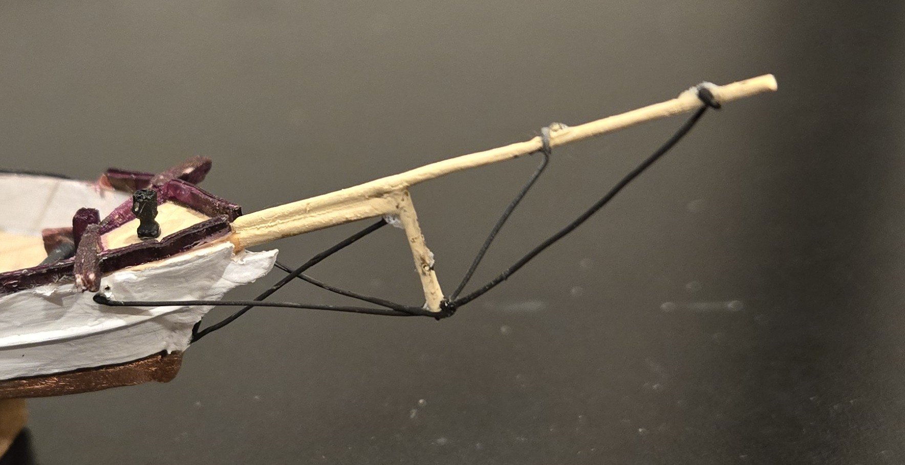
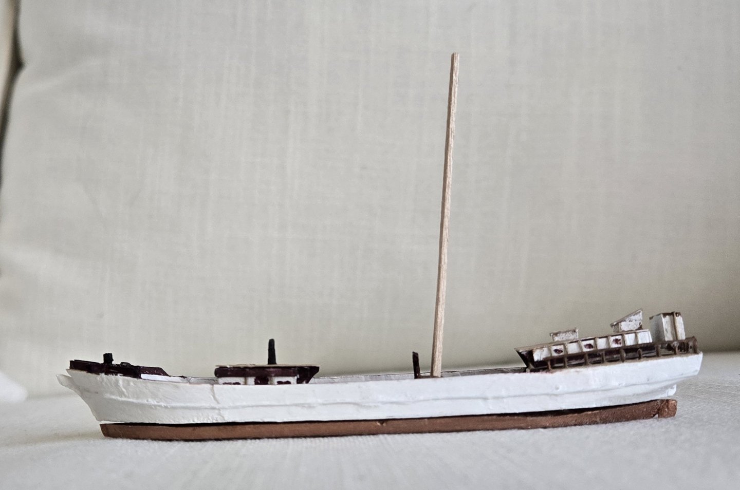
Pic 1 shows the mainmast folded down and in the neck of the bottle. There appears to be plenty of room for the foremast and its yards (thank heavens!) Pic 2 shows a few new things: 1) A block of wood fastened to the bottom of the hull which allows it to be clamped - I'm using a clamp designed for a drill press. All the instructions that I've seen use a block like this but I didn't use it until I finally saw how useful it is for parts of the rigging process. 2) The foremast is complete (but not hinged) and 3) the head gear is started. Oh and 4) you can see a sailor leaning against the port bulwark rail. The bowsprit is wood but the jibboom and martingale are 1mm brass rod that have been flattened so that 0.50mm holes can be drilled in them Pic 3. I've rigged a single bobstay rather than the correct double because I just could not figure out how to get the second one in there and it might look too cluttered anyway. The martingale stays are in but I won't be installing any head stays below the jibboom - they'll just end at the jibboom after they have been used to raise the foremast. I haven't figured out what to do with the guys yet because they may look too bulky and I can't fit whisker booms because they won't fit in the neck Lastly for this post is the yards Pic 4. Wood is used for the fore yard but wire is used for the upper four yards as they would be just too fragile if made from wood. I'll taper the fore yard but the other four will have to be straight.


-
If you did leave MSW then it really is odd since both myself and ccoyle experienced the same problem. Maybe you did something before you left that initiated a save?
-
James did you completely leave MSW or just go to a different window. If you did leave MSW then it really is odd since both myself and ccoyle experienced the same problem. Maybe you did something before you left that initiated a save?
-
Need thread about 0.1mm in diameter
Doug McKenzie replied to Doug McKenzie's topic in Masting, rigging and sails
Thanks all! I found some on Amazon - I don't know why I couldn't find this the first time I was looking. -
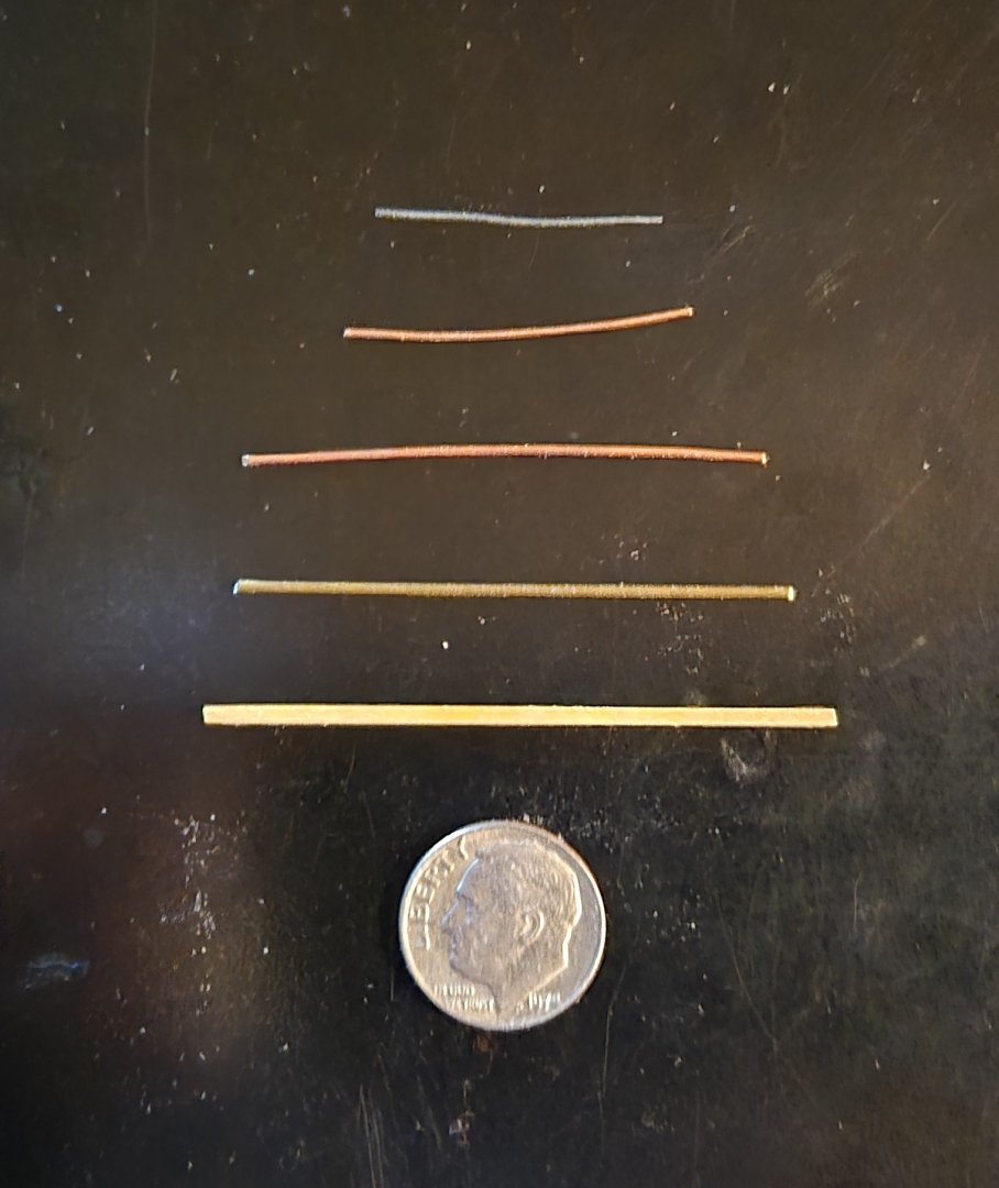
I have only been able to find thread down to 0.3mm and I'm working on a Leon-in-a-bottle model at 1:300 which requires some 0.1mm tan thread for running rigging. Does anyone know of a source for thread this fine? I've attached a picture that shows the peak halyards as 0.3mm black and you can see that it is way to heavy. The hull is about 4" long. Thanks in advance. Doug

-
Pic 1 shows the hinged mast vertical. Pic 2 shows it folded down. Pic 3 shows the hinge - wire through the base of the mast bent down along the mast and inserted into two holes in the deck just aft of the gallows, Pic 4 shows the shrouds in place. These are all one piece of thread wrapped around the hull and passing through one relatively large hole just above the trestle-trees between the lower mast and the topmast. The two backstays will be placed correctly later. The peak halyards pose a pretty big problem because they are too thick, 0.30mm, they should be 0.10mm. In addition, they should be tan instead of black. I am going to ask one of the forums for help on finding finer thread because this just doesn't look right.


-
Folks, It used to be that I could start to build a posting and then quit MSW and when I came back my work was saved. I could continue to build the posting and then eventially submit it. Now my work is deleted. Is there some way I can have the old functionality back or is this a permenant change? Thanks Doug
-
The main top, consisting of trestle-trees and cross-trees along with the cap (made of thread), is shown in Pic 1. Pic 2 shows most of the rigging for the mainmast as it will appear in the finished bottle. There are only two classes of rigging that are not included yet. One is the main lower shrouds which can't go on until the mast is hinged to the hull. The other is the fore braces. I haven't decided yet whether to put the braces on the mainmast before hinging or after. To have another 10 braces hanging around before they can be fastened to their respective yards seems to be too messy - we'll see. I also haven't decided whether to build the foremast next with its five yards or whether to hinge the mainmast and rig the main lower shrouds and the backstay next.

-
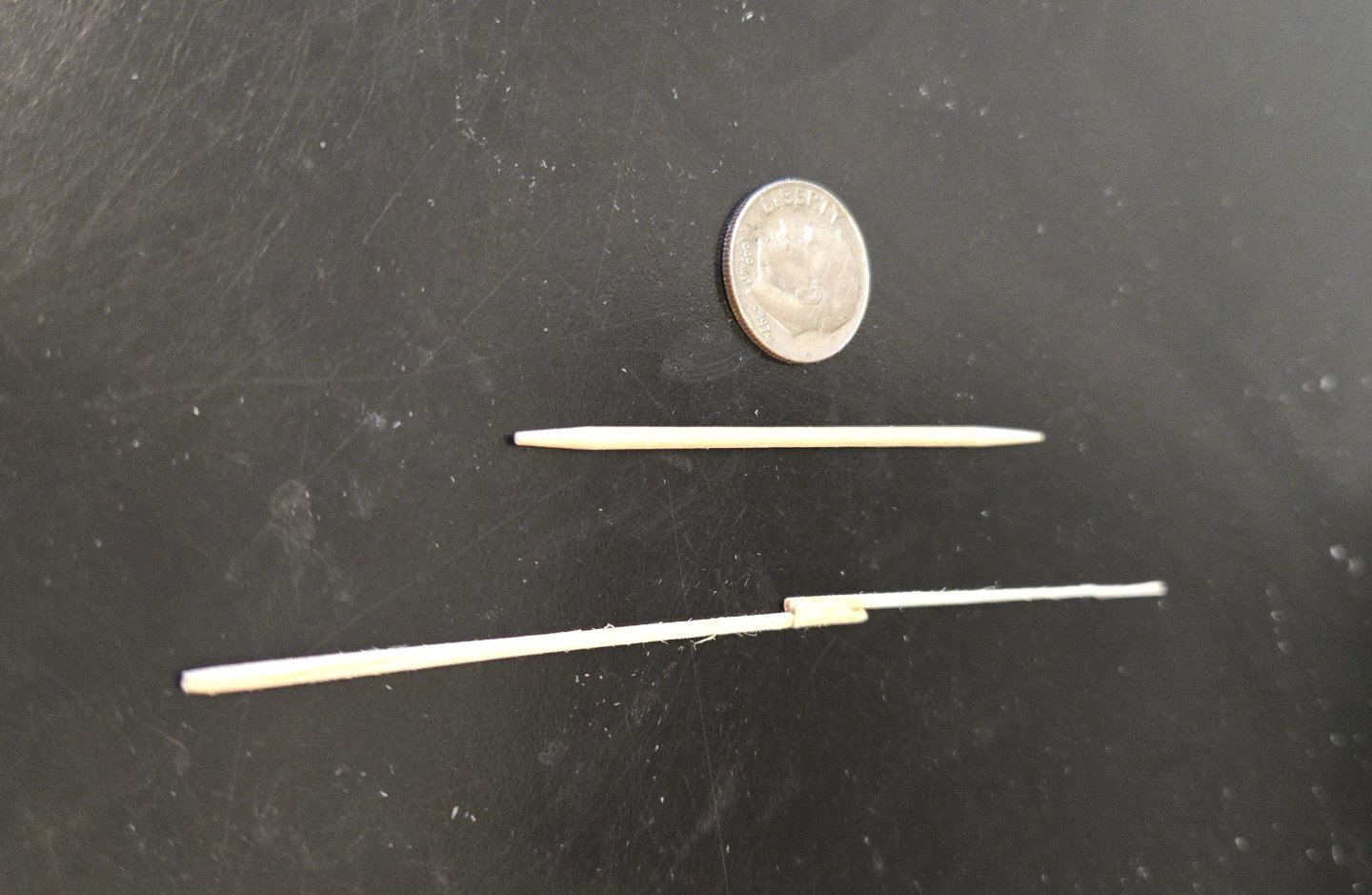
We are starting with the mainmast for two reasons -First, It is thinner than the foremast and therefore a good way to test construction tecniques. The second reason to start with the mainmast is that it folds down independent of the foremast whereas the foremast folds down on top of the mainmast. I sanded a 3/32" x 3/32" piece strip of balsa down to the 1.6mm size at the parners using a sanding stick. My gut says that balsa wood soaked in very thin CA glue will be a) Easy to size and taper and b) Also have plenty of strength, so that is my first try. That same guy Marty suggested using the thin CA to make the card bulwarks strong so we just adapted the idea to the spars. Having tapered the lower main with a square cross section down to 1mm at the head, I realized that drilling the various holes might be easier if I kept the square cross section. Unfortunately, this increases the visual diameter by 41% (the diagonal of the square being the new visual diameter. So what I'm going to try is leaving rougly the top half square, breaking the corners for a bit below and in the lowest part, rounding it off. Making the main topmast the same way and joing them at the doubling gives Pic 2 which is before soaking the mast in CA glue. The toothpick is 1.8 mm in diameter (5/64'). After the very thin CA is applied and sanded, the nice yellow color seems appropriate (Pic 3) for the final appearance of the spars. The glue brought up a lot of the balsa fiber and so a good fine sanding was needed because I imagine that to raise the masts in the bottle easily, we don't want the rigging to be catching on rough fibers on any of the spars. Next we'll be constructing the main top and then start rigging the mainmast.

-
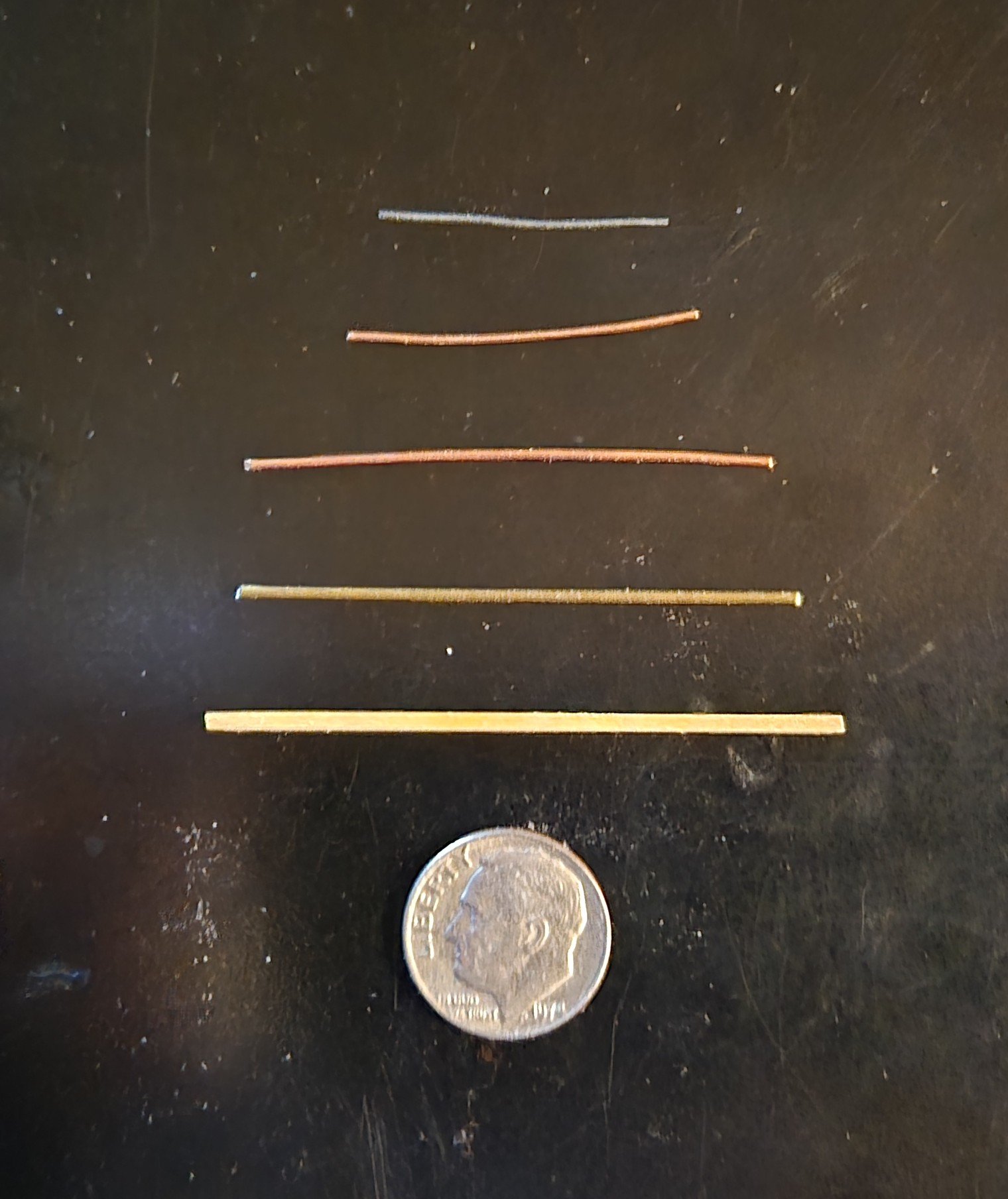
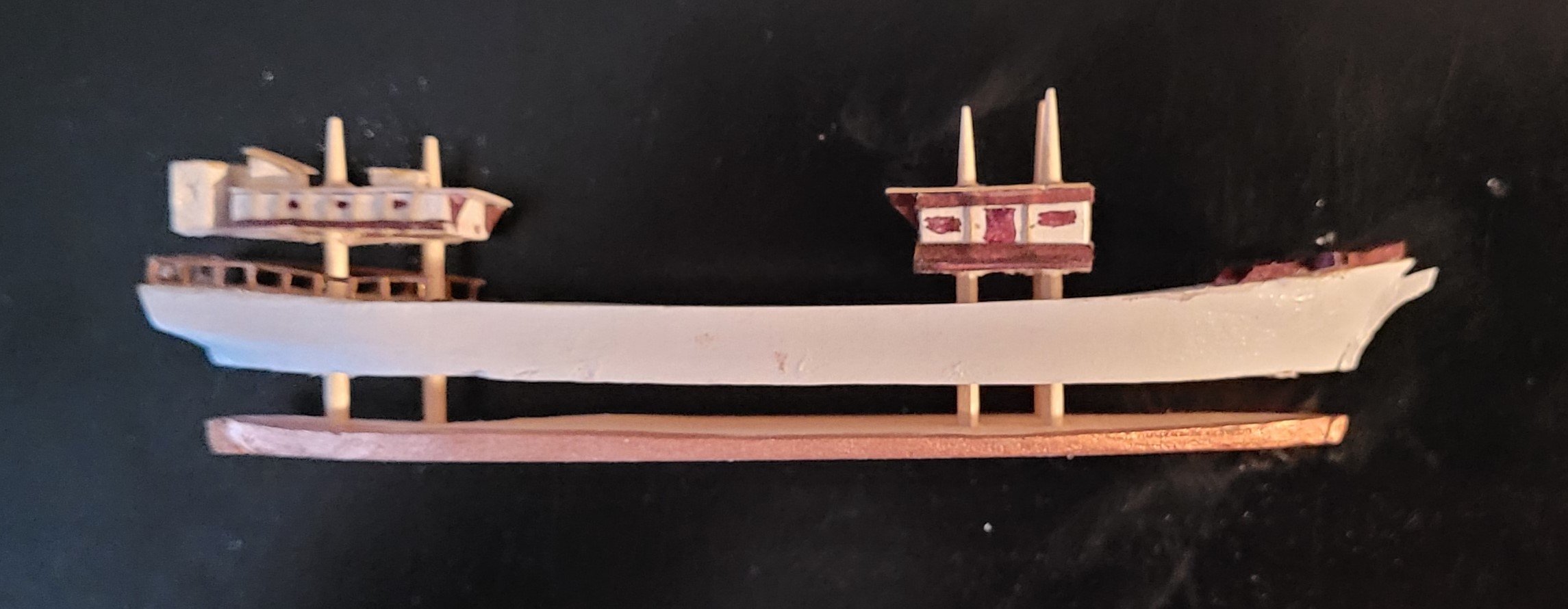
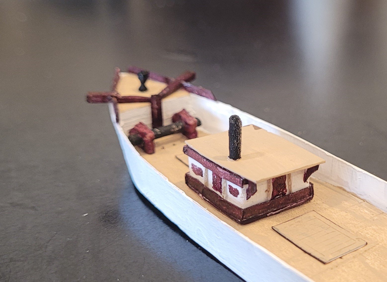
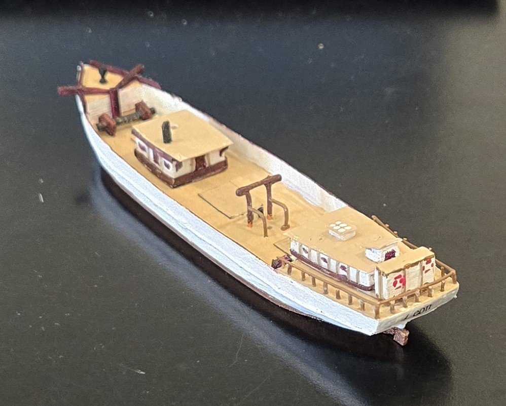
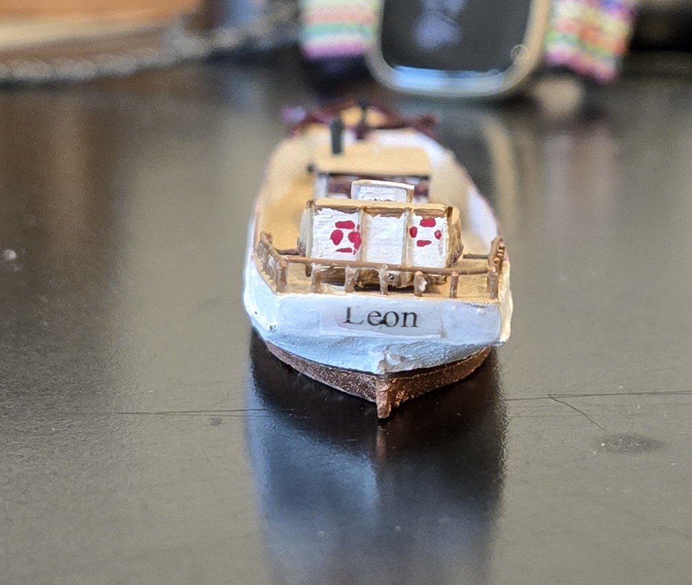
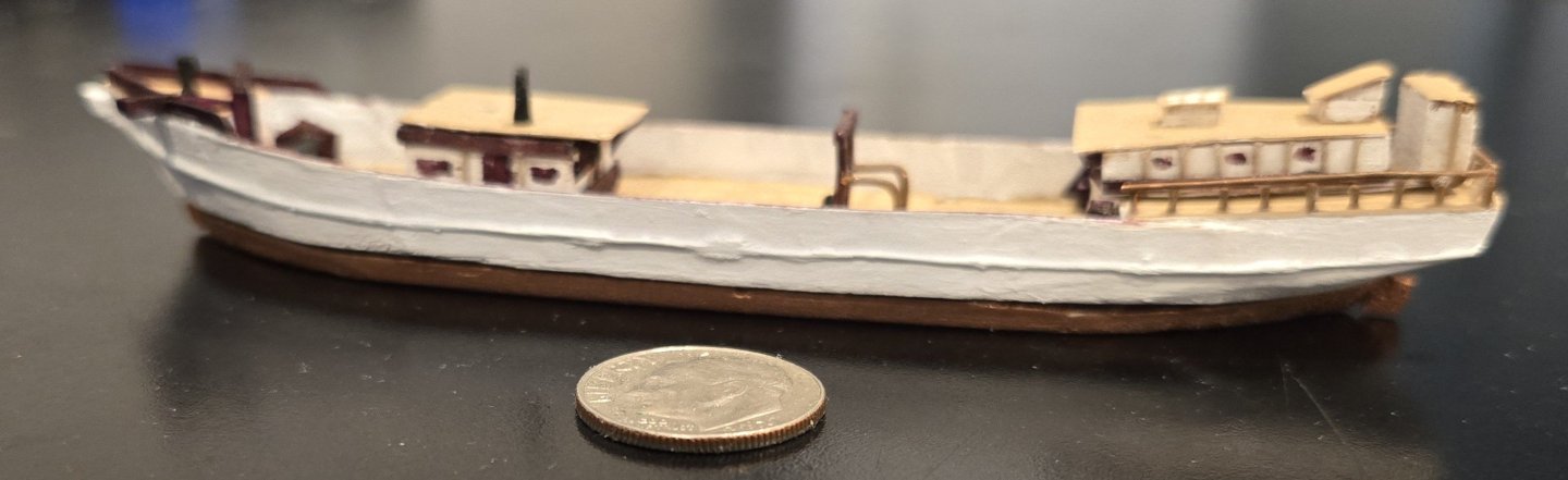
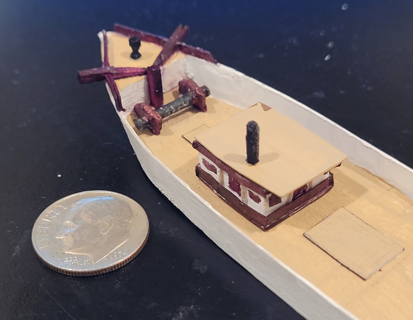
The 4 parts of the hull, that will be inserted into the bottle separately, have been prepared with toothpicks to be properly aligned when glued together - Pic 1. . The toothpicks, of course, need to be trimmed! Credit for this solution goes to my friend Marty Nusbaum - I didn't want to drill down from the top and mar the roofs but I couldn't drill from the bottom because the model wouldn't sit securly on the drill press. Marty pointed out that if I drilled down from the top, I could just fill the holes (which I did with toothpick plugs) and paint over! Work was delayed about 2 weeks until this problem was solved. The main fife rail has been added along with the gallows (to support the main staysail boom) - Pic 2). The heads of the bilge pumps have also been added (black, just forward of the gallows). And the wheel shelter has been added with two little life buoy rings painted on the aft bulkhead. The 'Leon' name plate is on the transom - (Pic 3). And, lastly, a moderately successful attempt has been made to show the wale emphasizing the lovely sheer curve - (Pic 4). A thin wire + glue was used. I've included the dime not so much to show scale but to make excuses for the not-exactly perfect wale. The hull is now complete and we can begin work on the spars and rigging - oh boy, I can only hope that lady fortune will be with us when we try to produce scale spars!

-
The windlass supports were so out of scale I just had to improve them. In the last post, those supports are about 23" thick. The best estimates I could make from various drawings was that they would be somewhere between 6" and 12" thick. So I sanded them down to about 12". Next we have the wheel-shelter and the main fife-rail and the hull will be complete.
-
For starters, I won't be fixing the anchor after bulkhead - I've just ignored it!. In the meantime, the wash-strake around the anchor deck, capstan, catheads, pawl bitt and anchor windless have all been added - Pic 1