HOLIDAY DONATION DRIVE - SUPPORT MSW - DO YOUR PART TO KEEP THIS GREAT FORUM GOING! (89 donations so far out of 49,000 members - C'mon guys!)
×


Doug McKenzie
-
Posts
221 -
Joined
-
Last visited
Content Type
Profiles
Forums
Gallery
Events
Everything posted by Doug McKenzie
-
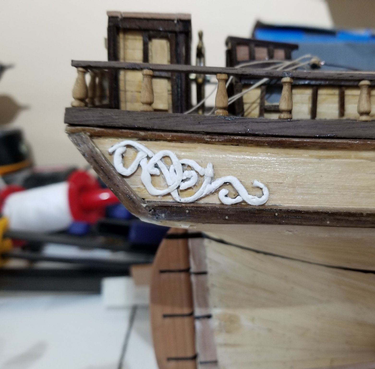
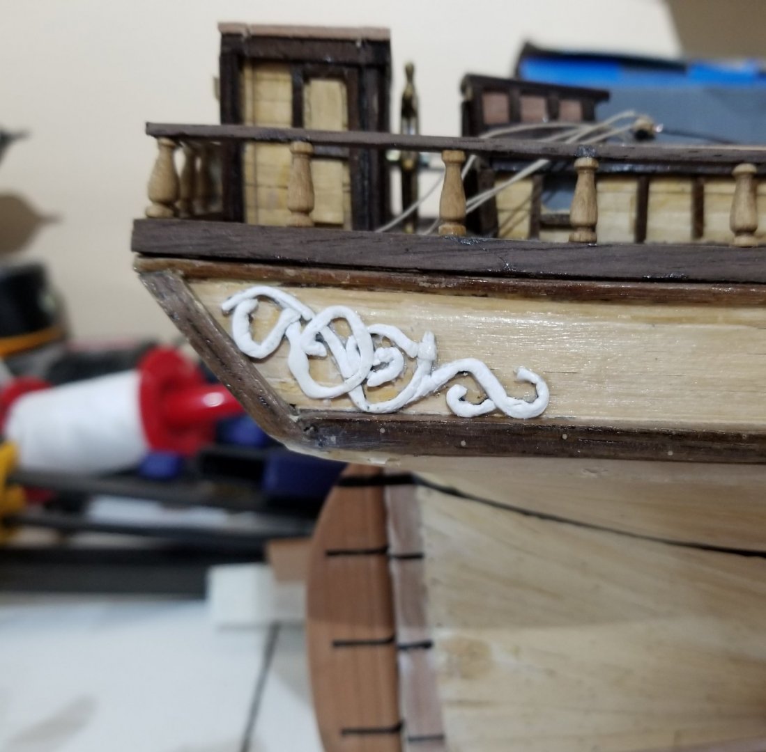
Thanks GrandpaPhil, I think this modeling must really be a labor of love otherwise why would we ( graciously? ) accept all the failed experiments. Meanwhile, I've painted the scrollwork black because of the drawing that Beckman posted on December 14, 2018 from Aust-Agder-Museum. I'll post more pictures when I finish all the scrollwork \ Thanks again for the affirmation,, Doug
- 108 replies
-
- 3
-

-
- leon
- brigantine
- (and 1 more)
-
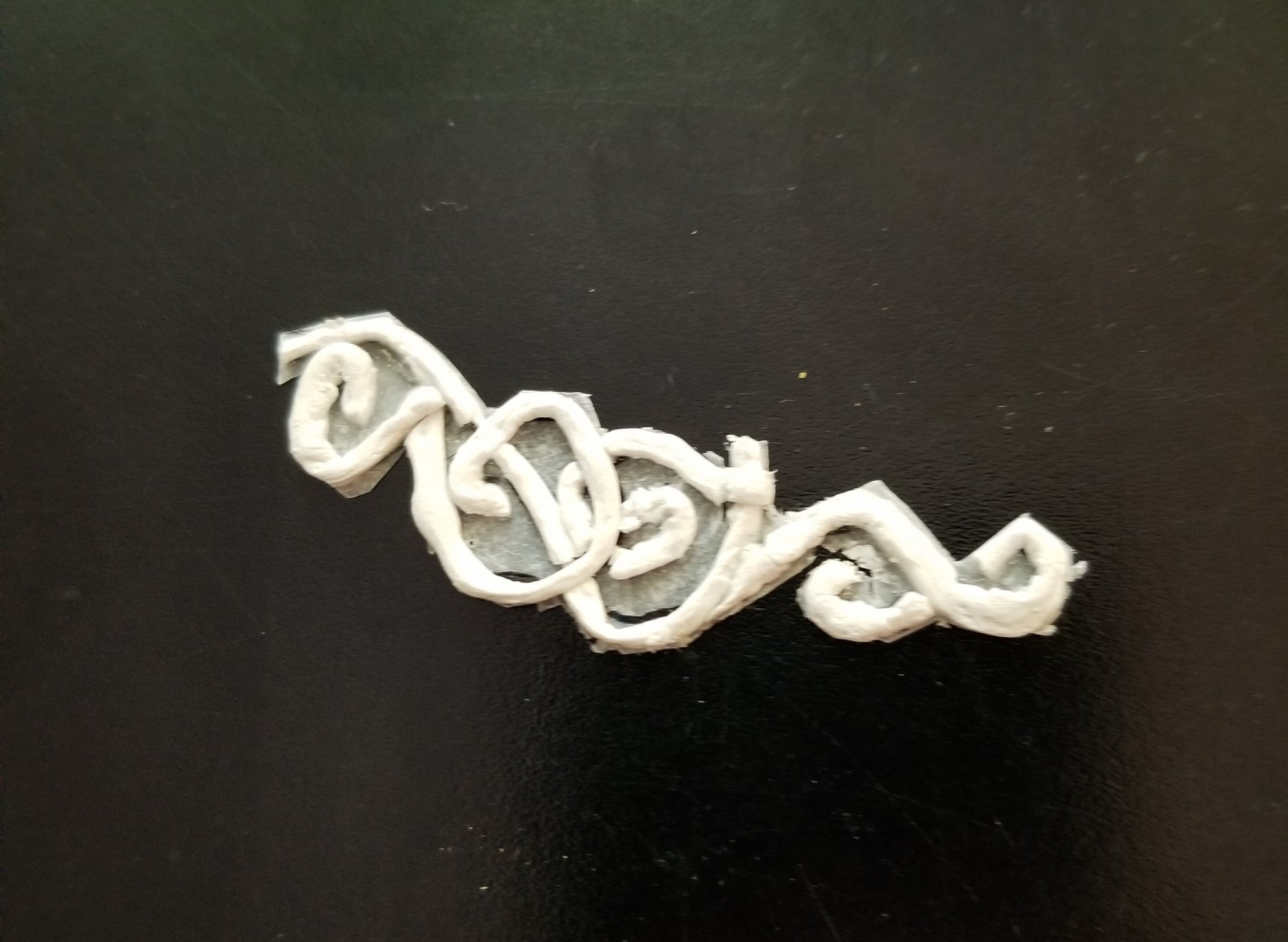
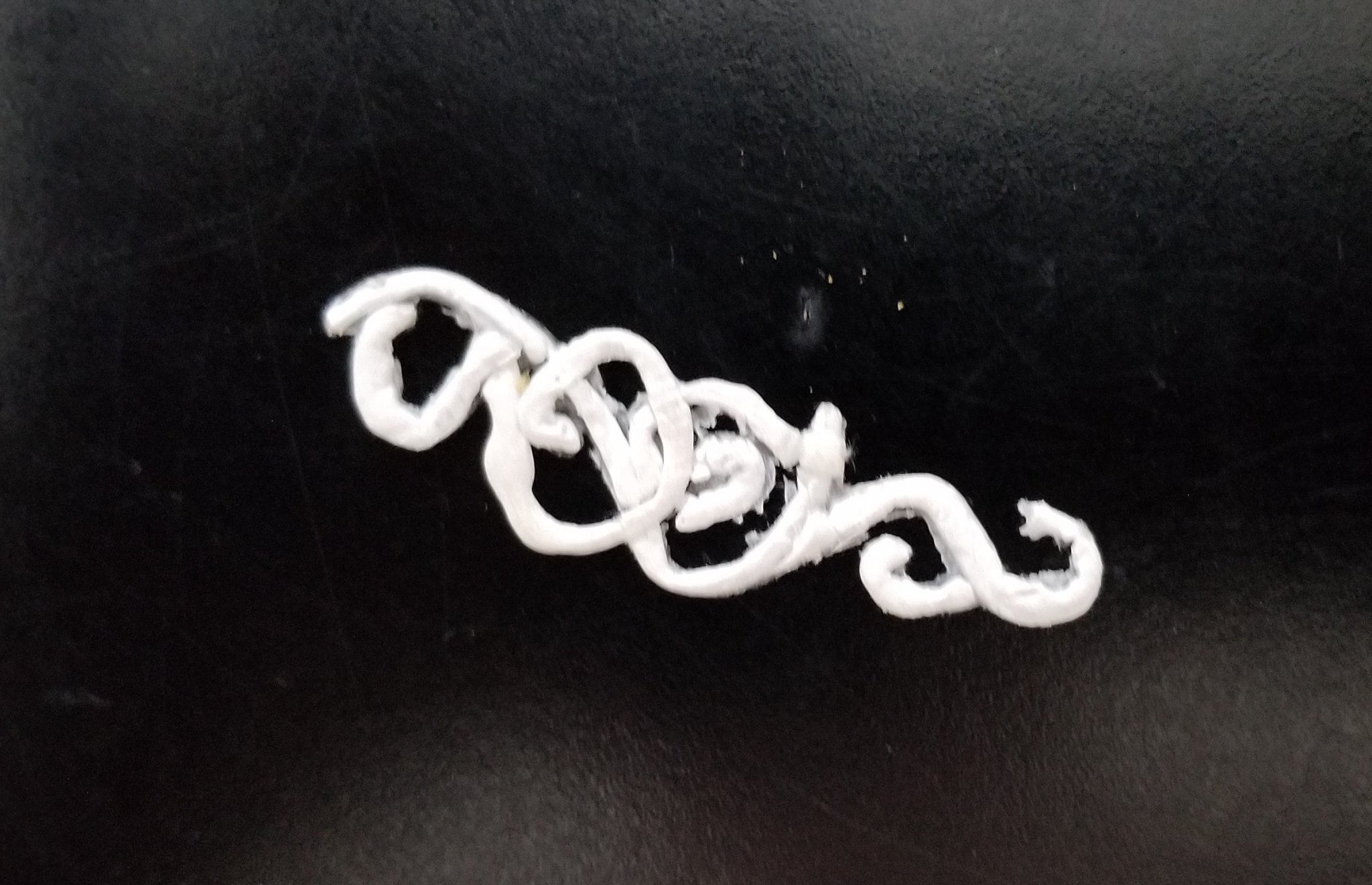
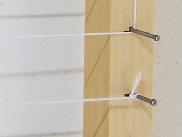
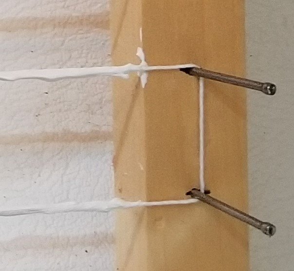
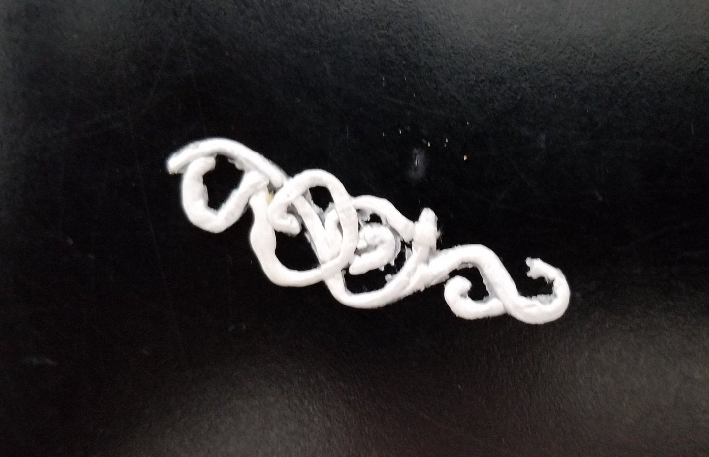
At this point I figured that if I'm going to do the scroll work I better do it now. There was no way I was going to carve the scroll work or paint it so I asked if anyone would be willing to take on a commission of doing the carving for me. What I got instead was great advice from David Antscherl, aka druxey. Instead of carving out the wood, he said, why not build up the filigree with something. He recommended trying string and gesso. I don't have the skill to paint the gesso freehand so I used kite string coated with 4 coats of gesso. The first picture shows the kite string strung between nails. The second pictures shows the kite string coated with 4 coats of gesso. We'll try to reduce the unevenness of the gesso but that comes later. This gesso coated string is then easily bent to follow the curves on the tracing of the scroll work . The end of the string is first tacked to the tracing paper with CA. Then with needle pointed tweezers, the string is bent around the curves of the scroll work tacking it in place with CA when ever necessary to hold the curves. The following pictures show first, the filigree right after gluing the gesso coated string to the pattern. The second picture shows the filigree after it has been cleaned up. The clean up is done with tiny files and consists of 1) removing the tracing paper so that it won't be visible and 2) Rounding off kinks and corners so that the curves are all smooth. The last picture shows the filigree glued onto the .hull. It's pretty rough but at least I was able to do it.

- 108 replies
-
- 4
-
-
- leon
- brigantine
- (and 1 more)
-
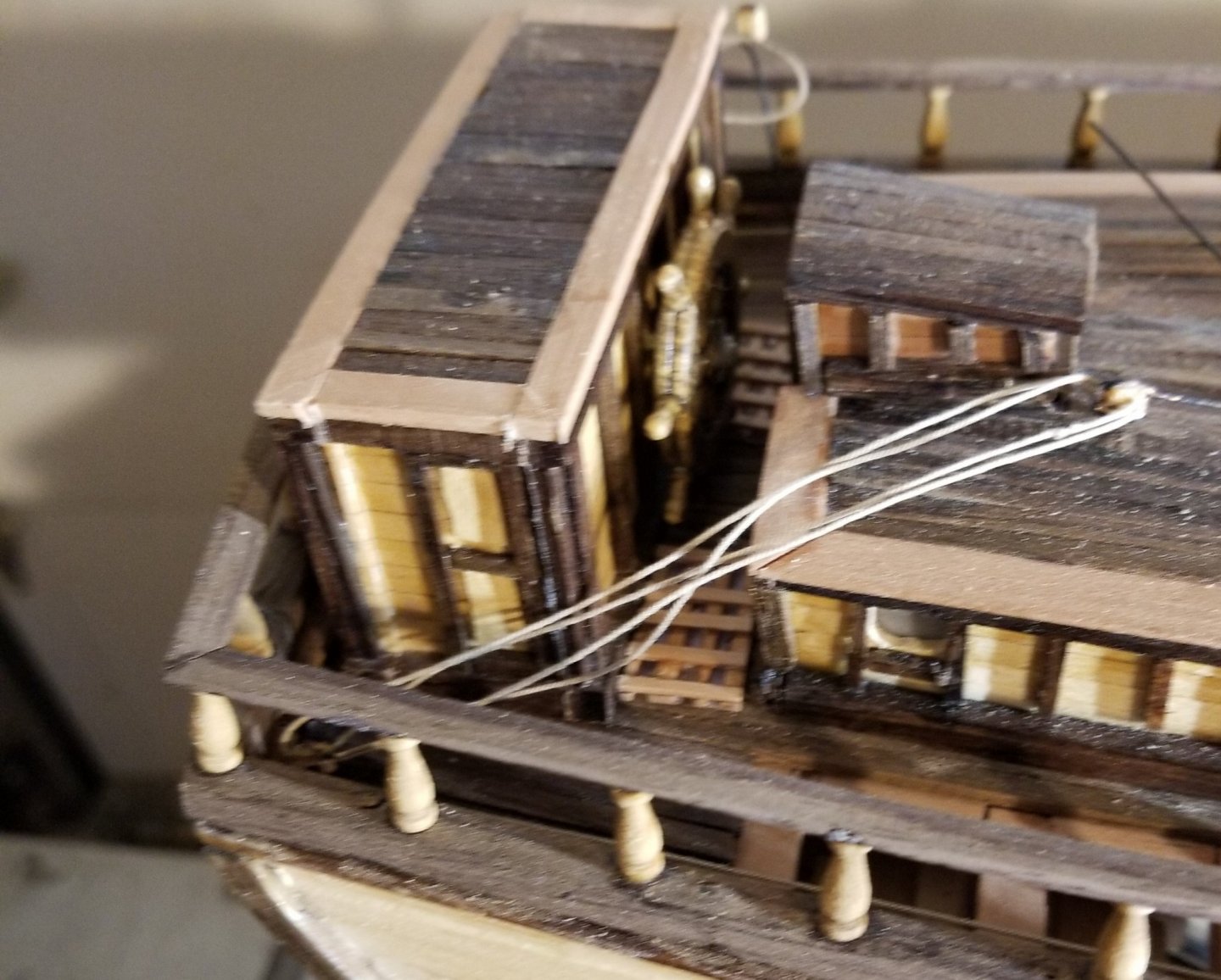
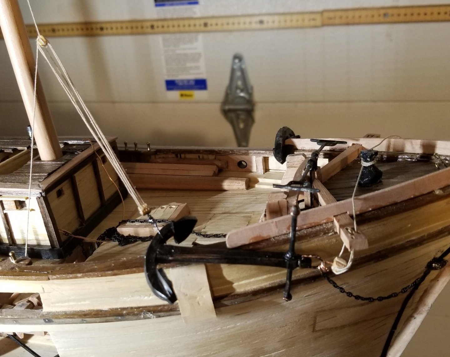
Some miscellaneous items on the deck - First is the spanker sheets. These are a problem because the double block shackled to the deck would be very difficult to install after the wheel box is in place. and even more difficult would be threading the sheet itself through the sheaves of that block. Therefore the whole tackle is assembled and installed. The fife rail and bilge pumps are next. The hand-bars for the bilge pump are included so that the operation of the pump is clear. The anchor operation is shown next. The anchor chain can be seen entering the hause pipe which it passes through to the anchor windlass which can't be seen in this picture. The head of the anchor is seen hanging from the cat-head tackle which has been taken to the warping capstan to provide the power to lift the head of the anchor from hanging below the hause pipe to hanging below the cat-head. Lastly, a large hook at the bottom of the treble block fish tackle engages one of the flukes and the tackle lifts the fluke over the rail. The bill board is the wood plank that prevents the flukes from damaging the planking, the wale and the rail. This is the way the starboard anchor will be displayed in the final model. The port anchor will be stowed.

- 108 replies
-
- 6
-
-
- leon
- brigantine
- (and 1 more)
-
I need ornamentation for a 1:48 model. Relatively simple as it is for a brigantine built in 1880. I'd be happy to discuss.
-
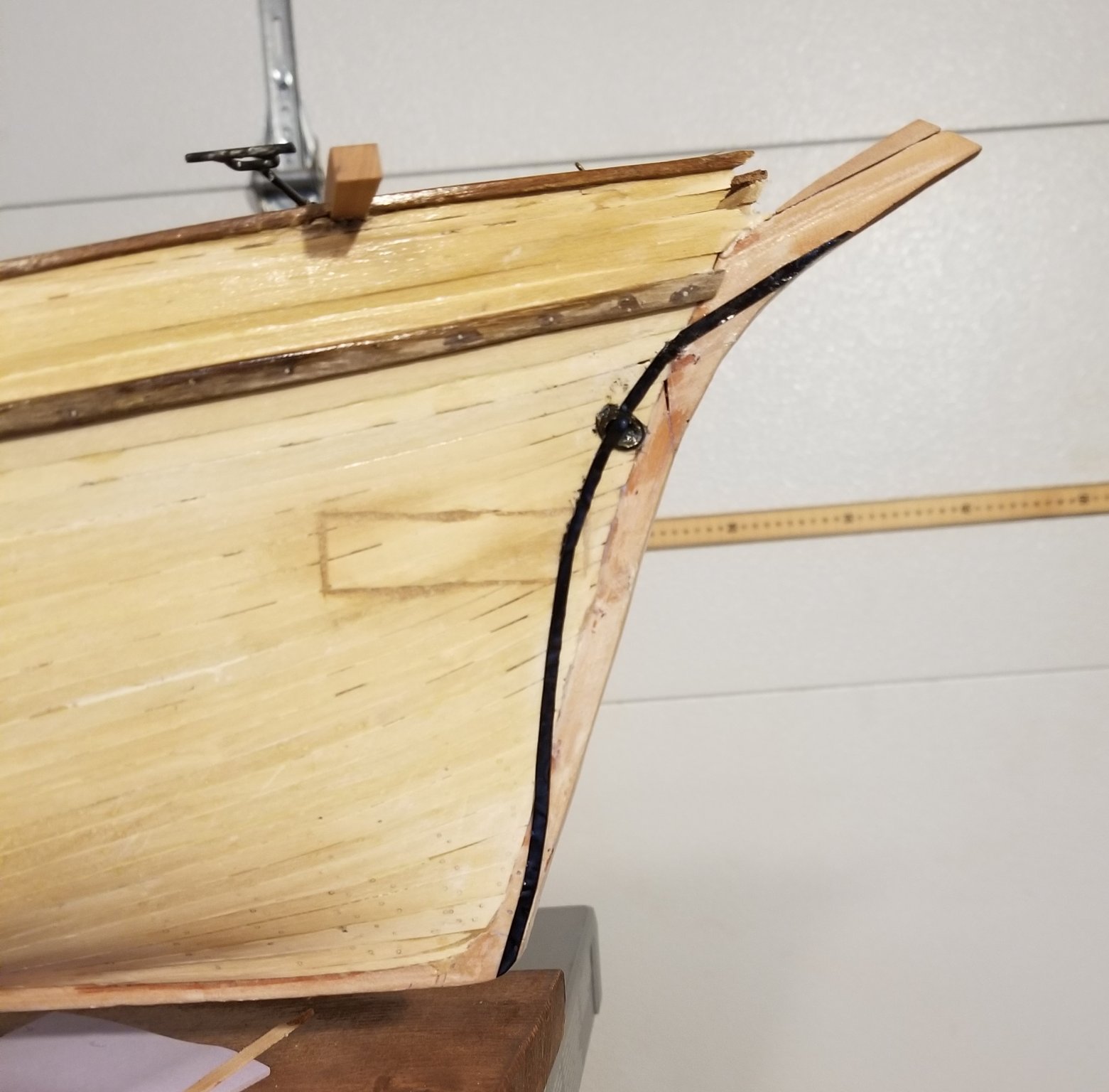
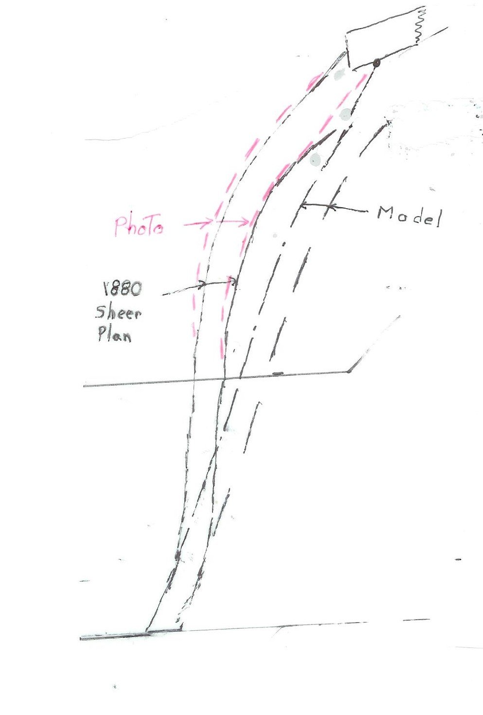
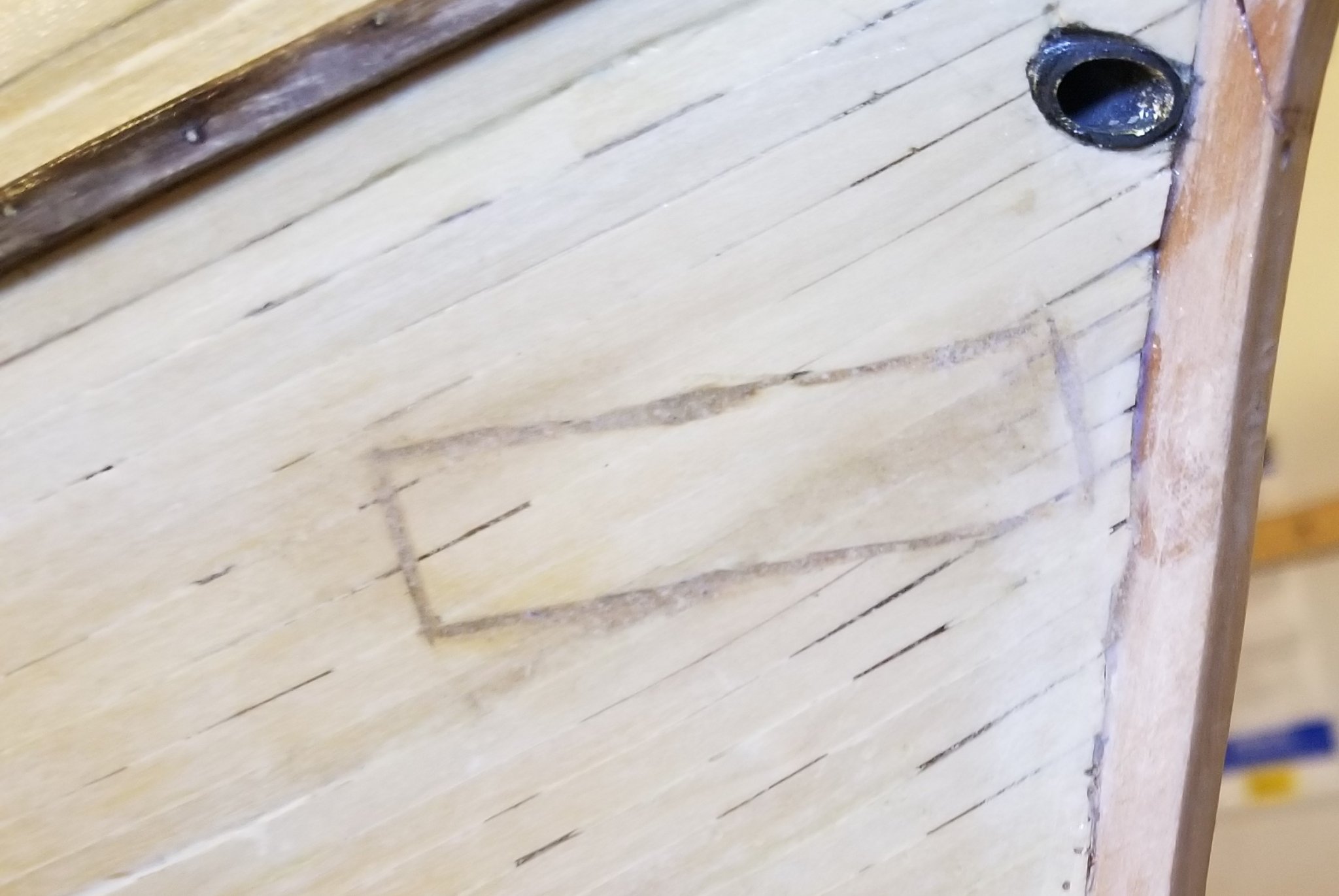
Ed, I also was pretty flabbergasted by the difference between Underhill's stem and the true stem. It is really odd since the photo shows the correct profile very clearly. As to 'other details of the plan' the good news is that the 1880 construction sheer plan agrees with the photo. I've read that these construction plans are not always trustworthy and yet, in this case, the stem shape is accurately reproduced.. And we know from previous posts that Underhill's deck layout is pretty close to the layout shown in the 1880 sheer plan so apparently we can be satisfied with the deck paraphernalia. This is a short posting but many hours of thought have gone into the result. I really wanted to modify the model to reflect the true stem. But no matter how many problems I solved more would arise and then I had the idea of 'painting' the true stem onto the model. This is practical because at every elevation the true stem is inboard of the model stem hence nowhere does the true stem project forward of the model stem. My ability to 'paint' the true stem is very marginal (you may remember the lumber hatch) therefore I asked a professional artist, Lisa Brown, to help. She proposed using 1/8" wide tape. She showed me how to ease the tape into position where there are curves. The final result is seen in the photo below.

- 108 replies
-
- 2
-
-
- leon
- brigantine
- (and 1 more)
-
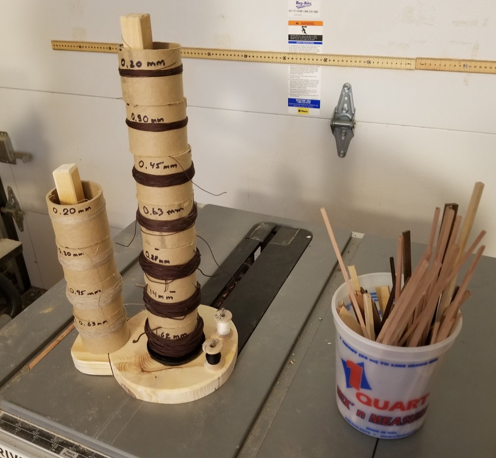
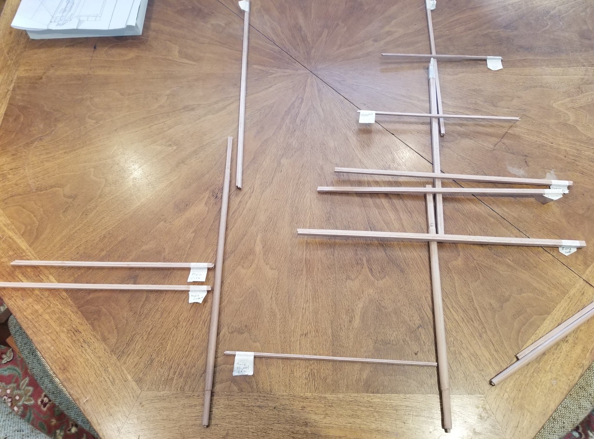
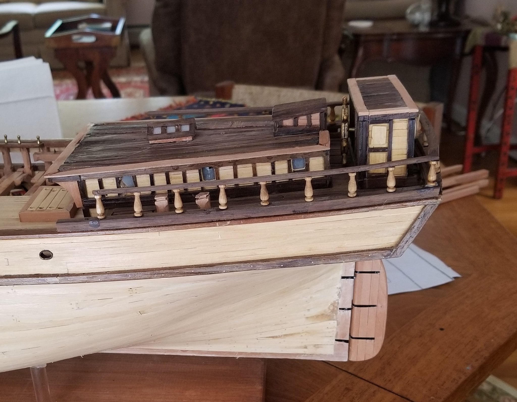
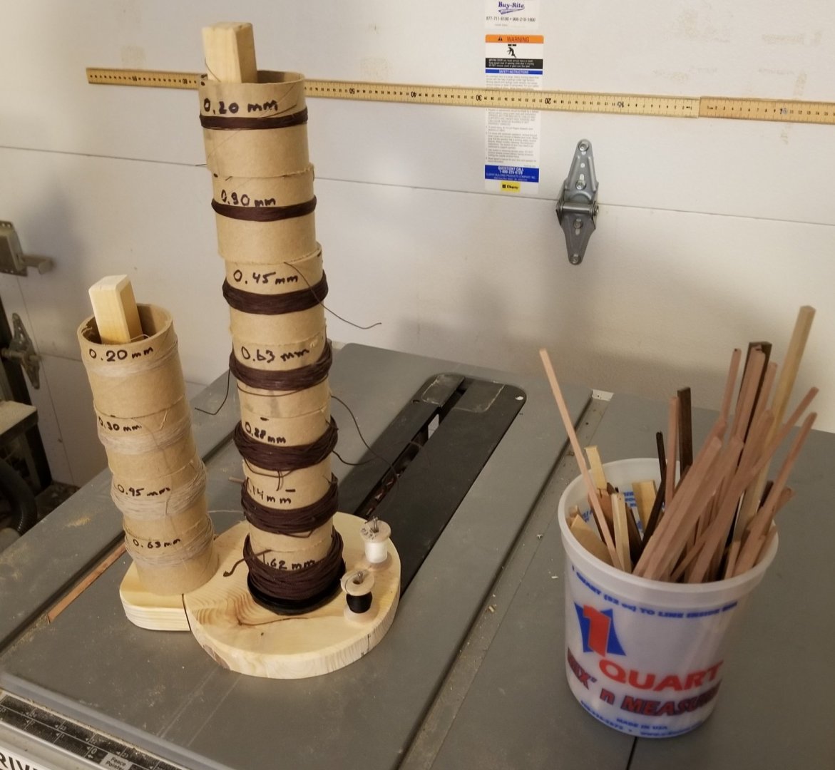
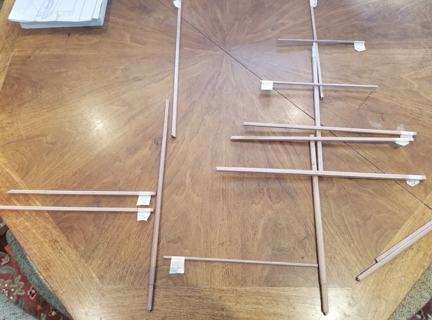
This posting includes some miscellaneous items as well as the beginning results of comparing the model to the picture. Having purchased all the miniature rope that I'll need from Syren, I realized that I needed to do some organizing. So first, I wound all the different sizes on 2" sections of 2" cardboard roller. Then, I stacked these 'spools' on two poles - one for the 7 sizes of standing rigging and the other for the 4 sizes of running rigging - voila! well organized with a small footprint. The little bucket with little sticks of all sizes and types of wood has also greatly reduced clutter on the bench top - I don't know why I didn't discover this years ago. Next, I've glued up all of the the 4 part spars - each spar has an extra inch at each end. As far as I can tell most ship modelers use a single stick for their spars and they have no problem with twisting or bending. For some reason, I've gotten it into my head that I need to make each spar from four sticks confident that they will then stay straight - I don't know where I got this idea. Comparing the model to the photo for the aft cabin showed that the companionway roof was too steep and that the skylight was too far aft and too high. Before and after photos follow. Unfortunately , I don't have a useful before picture so we make do. And lastly we compare the profile of the stem. We actually have two views of the stem one being from the photo and the other being from the 1880 construction sheer plan. It's encouraging that the photo and the construction sheer plan are basically the same as this means we can probably also trust the below waterline curve that the construction sheer plan shows.. Unfortunately, the model stem is straight and differs significantly from the true stem. It is not at all clear why Underhill did not follow the curve so clearly evident in the photo. Another disappointment is that I do not see how to 'fix' the model to match more closely to the photo. My son, Nate, trained as a naval architect, is not ready to throw in the towel on this. In addition he has software which constructs a 3-D model from a 2-D photo. We hope to extract further quantitative information from the photo. I'll remove some of the mystery of what's coming up by saying that I think I'll be building a third mid-ship deck house based on the photo. The good news is that it needs to be bigger hence making the case for housing the crew even more plausible.


- 108 replies
-
- 4
-
-
- leon
- brigantine
- (and 1 more)
-
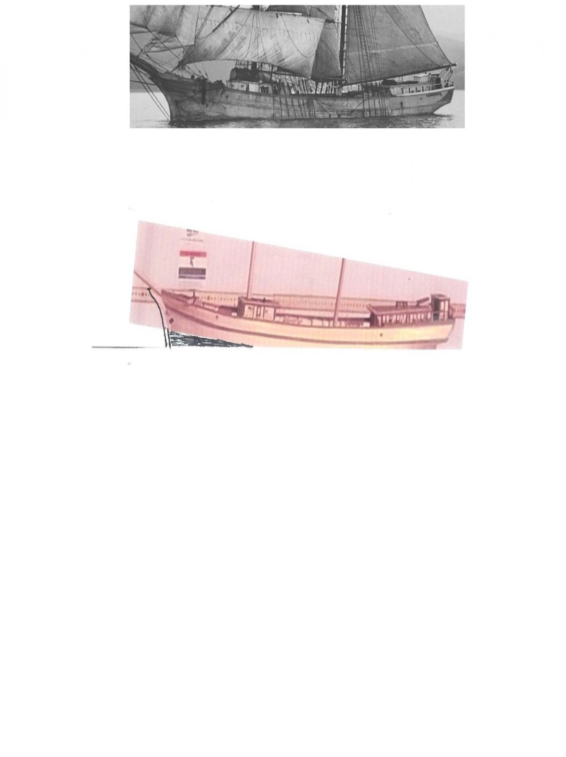
Ed, Great idea to start Leon again after all where are you going to find a more beautiful ship. If you do start her again and if your planning to show the interior then I'll send you the 1880 DNV survey which will tell you the correct number of frames, the correct sided dimension used for all the frames and the correct moulded dimensions of the mid-ship frame (and a LOT more). I had to use my 'curve' method for the moulded dimensions because I didn't find the survey until I was finished most of the planking. And of course be sure to start a log! I totally agree with Longridge. On a completely different topic I just recently came up with the idea of comparing the model with the well known photo of Leon and this is shown in the picture below. This is actually a difficult comparison to make because the photo of the model has to match 3 parameters of the photo of the real ship. 1 - The angles forward of the port beam have to be the same. The model has an angle of about 10 degrees and I believe the real ship's angle is more like 20 degrees 2 - The distances from the ship have to be the same. The distance for the model photo is 770' which might be pretty good. 3- The roll angle of the two photos have to be the same. In this case you can see that the starboard rail on the photo of the real ship is not visible but on the photo of the model it is very visible. In any event we certainly get the impression that the the model's bowsprit is steved a little too high and that both the foremast and the mainmast have too much rake. I have some ideas about how to determine better parameters for the model photo in order to check these impressions. I took the rakes off of a 1880 sheer plan but unfortunately those kinds of plans can be inaccurate. Good luck and many blessings, Doug

- 108 replies
-
- 2
-
-
- leon
- brigantine
- (and 1 more)
-
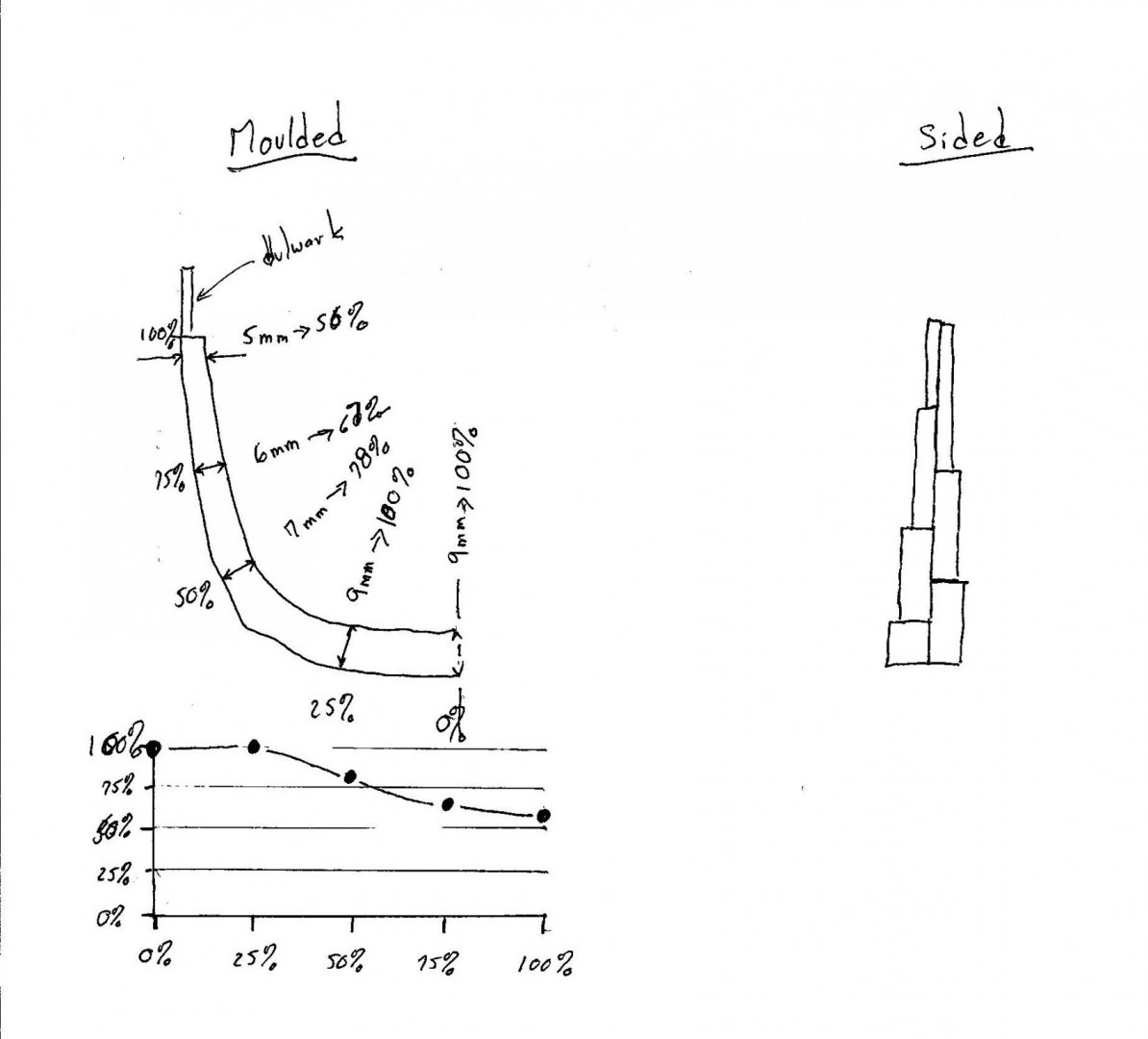
Hi Ed, You know, you are correct - I am very satisfied. For the first year or so I bemoaned my limited 'micro carpentry' skills - other builders seemed to have joints that you couldn't see, surfaces that were ultra smooth etc etc. But more recently when I look at her I see something that's almost alive even with her imperfections and I love it! As far as frames go there are two separate issues. The one I think you are asking about is referred to as the moulded dimension i.e. outside to inside. And yes you are correct that this dimension is thickest at the bottom (at the floors) and gets gradually thinner as you approach the upper most deck. The way I quantified this thinning was to look at some ships about the same size as Leon and assigning the positional value of 0 to the moulded thickness of the frame at the bottom (at the keel)- the actual thickness I gave as 100% because I'm expressing all the moulded thicknesses as % of the largest value at the bottom. Then I assigned the positional value of 1 to the moulded thickness at the deck and gave the actual thickness as, lets say, 56%. I think I then marked off positional values at 25%, 50% and 75% and assigned them actual thickness values as percentages of the max thickness. I compared these percentage curves for a few ships and generated a curve just by judgement that I used for Leon. I used the same curve for all the frames that went down to the keel. I don't remember how I adapted the curve for the frames that terminated on the deadwood rather than going all the way down to the keel. Another point, you need to have a diagram that shows both the outer curve of the mid-ship frame and also shows the inner curve. You probably will not find this on a plan but rather in a diagram in a book that shows a cross section of the construction of mid-ships. PS I only generated the curve for the mid-ship frame. I assumed that the same curve could be used for all the other frames. The second issue has to do with the other thickness of the frame - the sided dimension i.e. the fore-aft thickness. Every model I have built (and the vast majority of models that I've seen) have no tapering in this direction BUT in real life this is tapered also. I've seen that the segments (futtocks) that go into a real frame are a little thinner as you go up so the fore and aft surfaces of the frame are not smooth because each time a futtock gets thinner it introduces a little jog in the surface. I don't know if each futtock is also tapered a little. but I'll guess not. I'm attaching 2 drawings one for the moulded tapering and how I analyzed it to compare different ships and one for the sided tapering but remember I know very little about this. Good luck - I hope this is clear and helpful. Doug
- 108 replies
-
- 2
-
-
- leon
- brigantine
- (and 1 more)
-
The Pin Rails and Taffrail have been added. Both the belaying pins and the taffrail pedestals come from Model Expo. I haven't decided yet whether to paint the pins brown or keep them as raw brass.
- 108 replies
-
- 4
-
-
- leon
- brigantine
- (and 1 more)
-
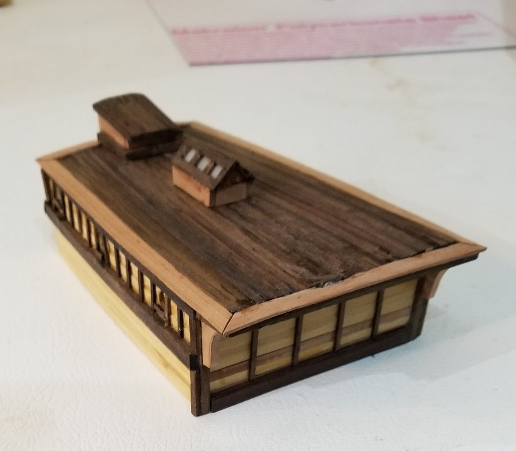
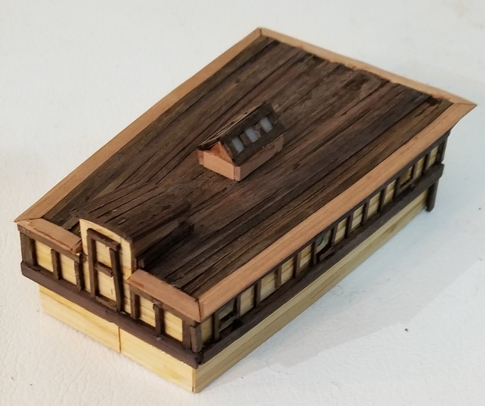
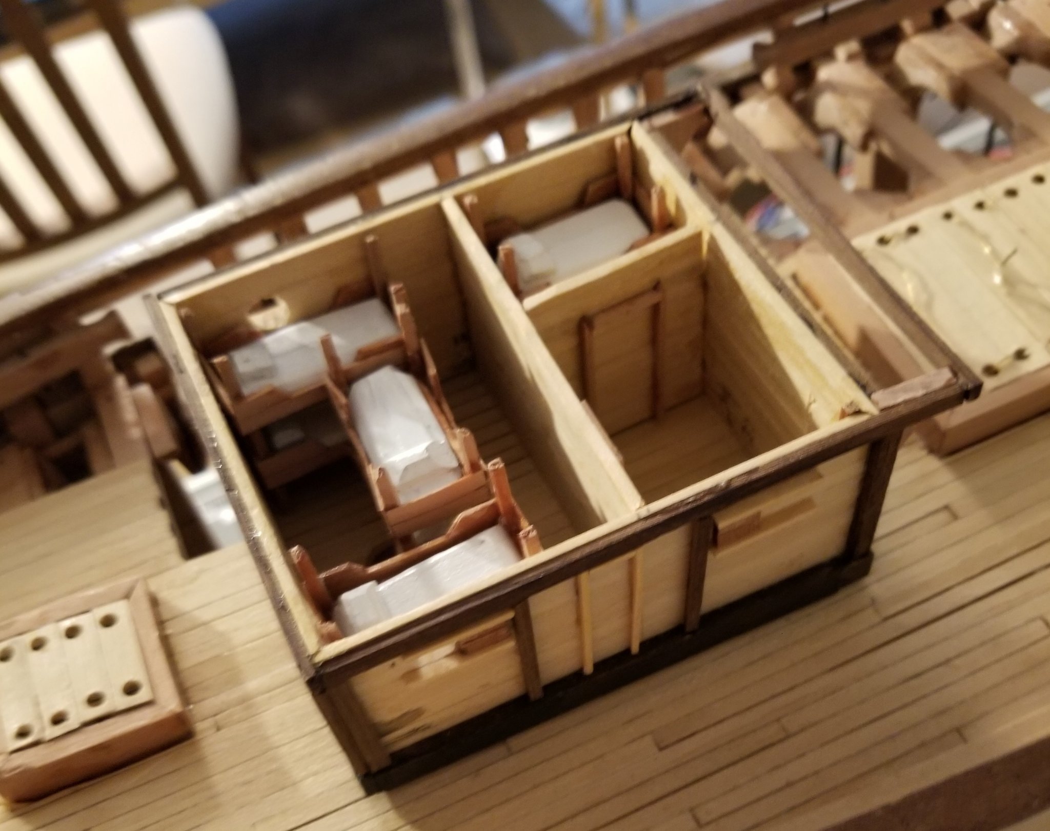
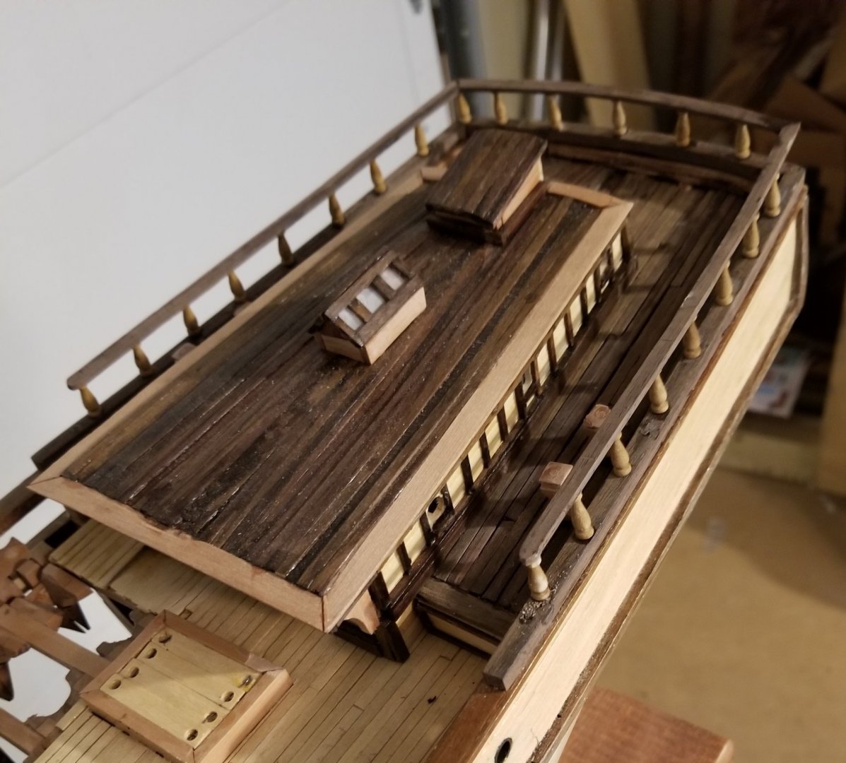
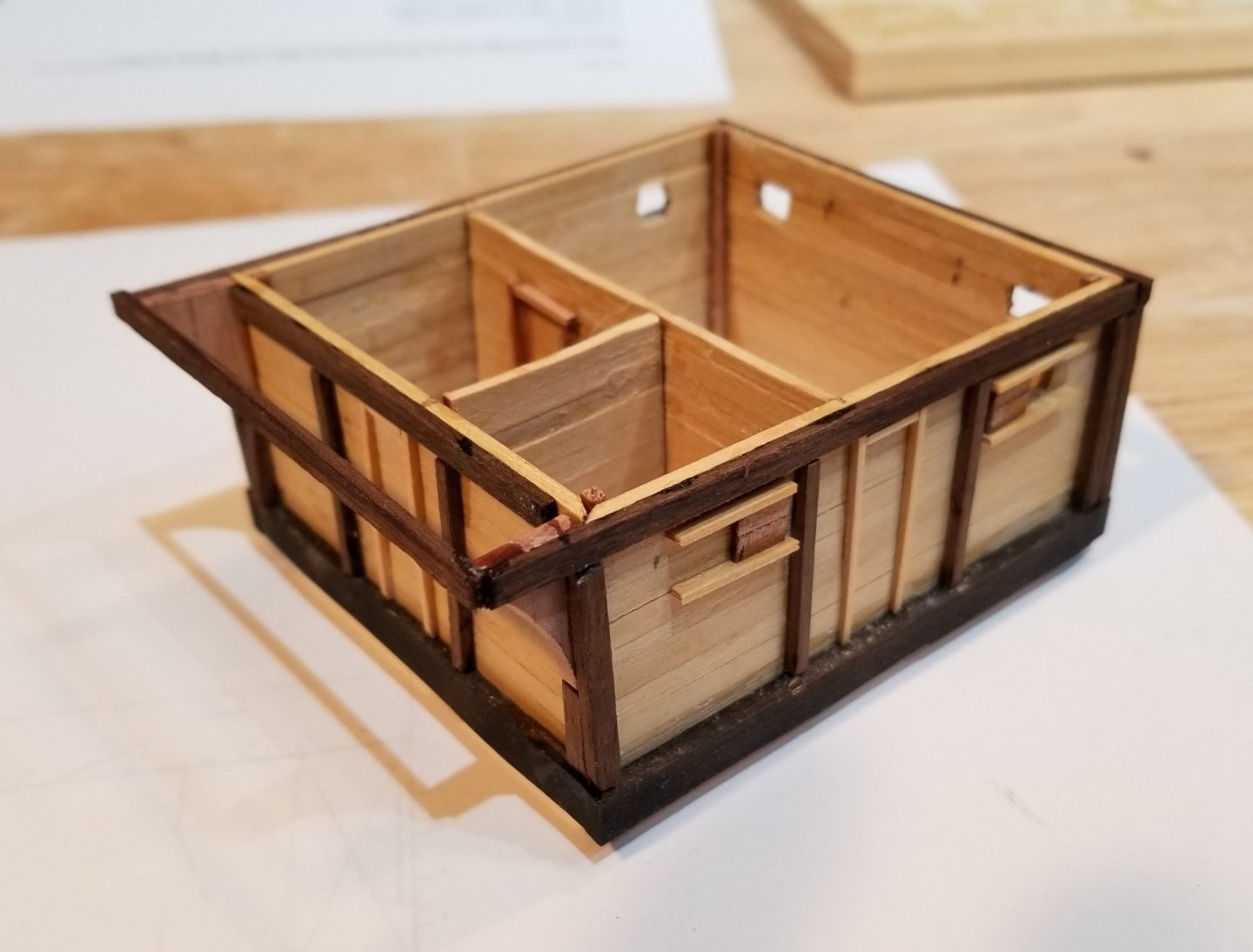
The aft house is now completed. It was constructed and trimmed pretty much identically with the mid-ship house so few construction photos are shown. In the following photo, the 4 walls of the aft house are shown tucked into the quarterdeck. Then the completed aft house is shown first facing aft and then facing forward. The planked quarterdeck is next followed by the completed aft house nestled into the quarterdeck. None of the internals of the aft house are being shown whereas some of the internals are shown of the mid-ship house. The reason for this difference is that the mid-ship house played an important role in trying to answer the question, "Did Leon's crew berth in a fo'c'sle or in the mid-ship house." There is no definitive answer but I feel the preponderance of evidence suggests they were in the deck house. It seemed reasonable to show that the deck house could actually serve this function so this is why I show the the 3 double bunks, the cook's "stateroom" and the galley and mess. This was particularly important because the size of the mid-ship house that I modeled was smaller even than Underhill's - 12.5' long compared to Underhill's 15' long. The 12.5' figure comes from an 1880 construction sheer plan.


- 108 replies
-
- 3
-
-
- leon
- brigantine
- (and 1 more)
-
Iron Band at the Heel of Masts
Doug McKenzie replied to Doug McKenzie's topic in Masting, rigging and sails
Et Al - Thanks for your creative contributions. I take this moment to announce that I am going to remove the mast hoops / mast bands / muffler belts / whatmacallit / gronicles from the heels of both the foremast and the main mast. My motivation for this is Bob's comment "I've seen my share of mast heels, a few in larger vessels and I've never seen one with a metal band around them" In addition no one else mentions ever having seen them. Since Leon is unlikely to have had a coaked mast, the rings are now history - they were my second exercise in silver soldering so they still had value. Bob, this is the second time I've followed your lead - the first was with the likely use of a built up mast step for Leon - I just hope that you are not a roboNRGMSWmember giving random answers to questions! Thanks all, Doug -
Iron Band at the Heel of Masts
Doug McKenzie replied to Doug McKenzie's topic in Masting, rigging and sails
Bob, Your answer has applicability far outside the nautical world. Therefore I would like your permission to quote you in fields far astray. For example, if my wife asks for the potato masher (we have three types of them in the drawer). then I can respond with Do you want the gronicle or one of the other two, And she can respond in kind when I ask her for a wrench. Thanks, Doug PS on a related subject was this iron ring standard issue on ships of all sizes and origins? -
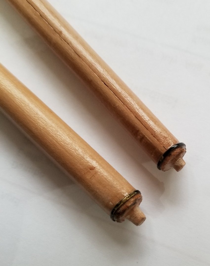
Underhill described (in book on Leon) an iron band around the heel of a mast presumably to prevent splitting. So I put these on (see picture below) Then I tried to find out what these iron bands are called. I used my modest ship library and the internet to make a pretty thorough search and came up with nothing. Not only did I not come up with a name, I didn't come up with any references to these iron bands at all. Therefore I am wondering were they used all that frequently. Any info on these bands will be much appreciated. Doug
-
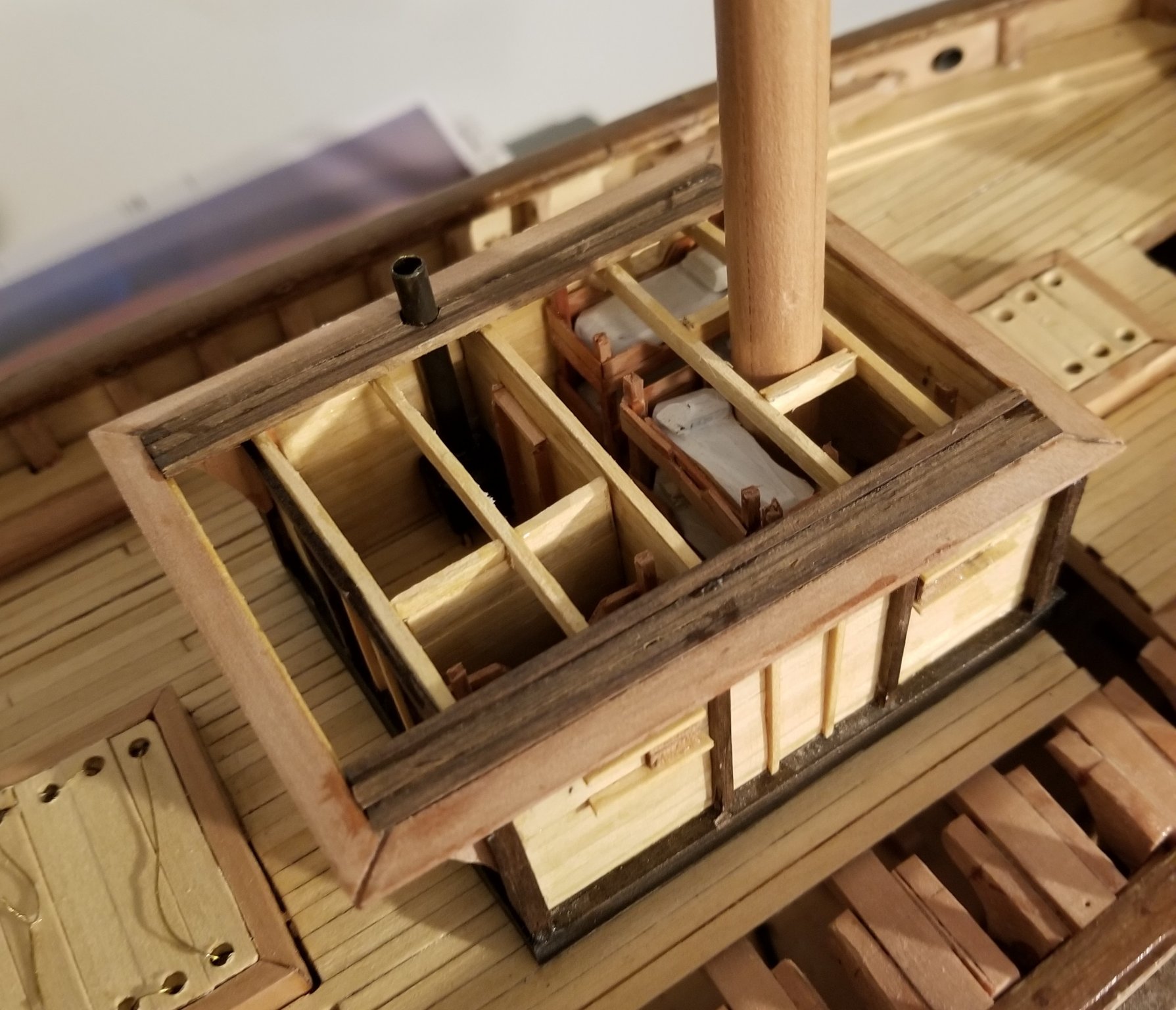
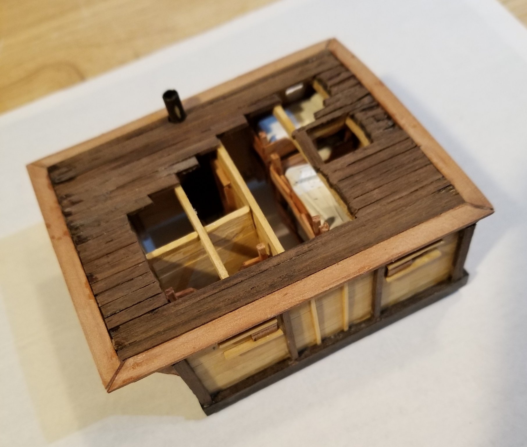
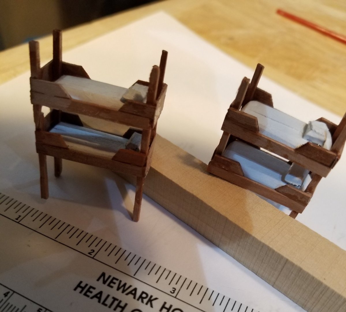
The Indian Rosewood trim has been added The bunk beds are assembled separately. and then inserted in place The roof beams are installed and a few roof planks are placed. You can also see the flue pipe for the stove. The roofing is completed taking into account the need to see the internals of the deck house


- 108 replies
-
- 8
-
-
- leon
- brigantine
- (and 1 more)
-
Sailor1234567890, Is it possible that your location, Shubenacadie NS, is the same Shubenacadie that is about 18 miles up river from Maitland NS? My grandfather grew up in Maitland and watched several ships built there. He even used to tell about being in the saw pits. I totally agree with "sweet pretty little thing" I am very pleased so far that her appearance doesn't seem to have suffered much from my modest woodworking skills but rather she has a sort of rustic appearance which I suspect is not too far wrong. Are you working on a build? Regards Doug
- 108 replies
-
- 1
-
-
- leon
- brigantine
- (and 1 more)
-
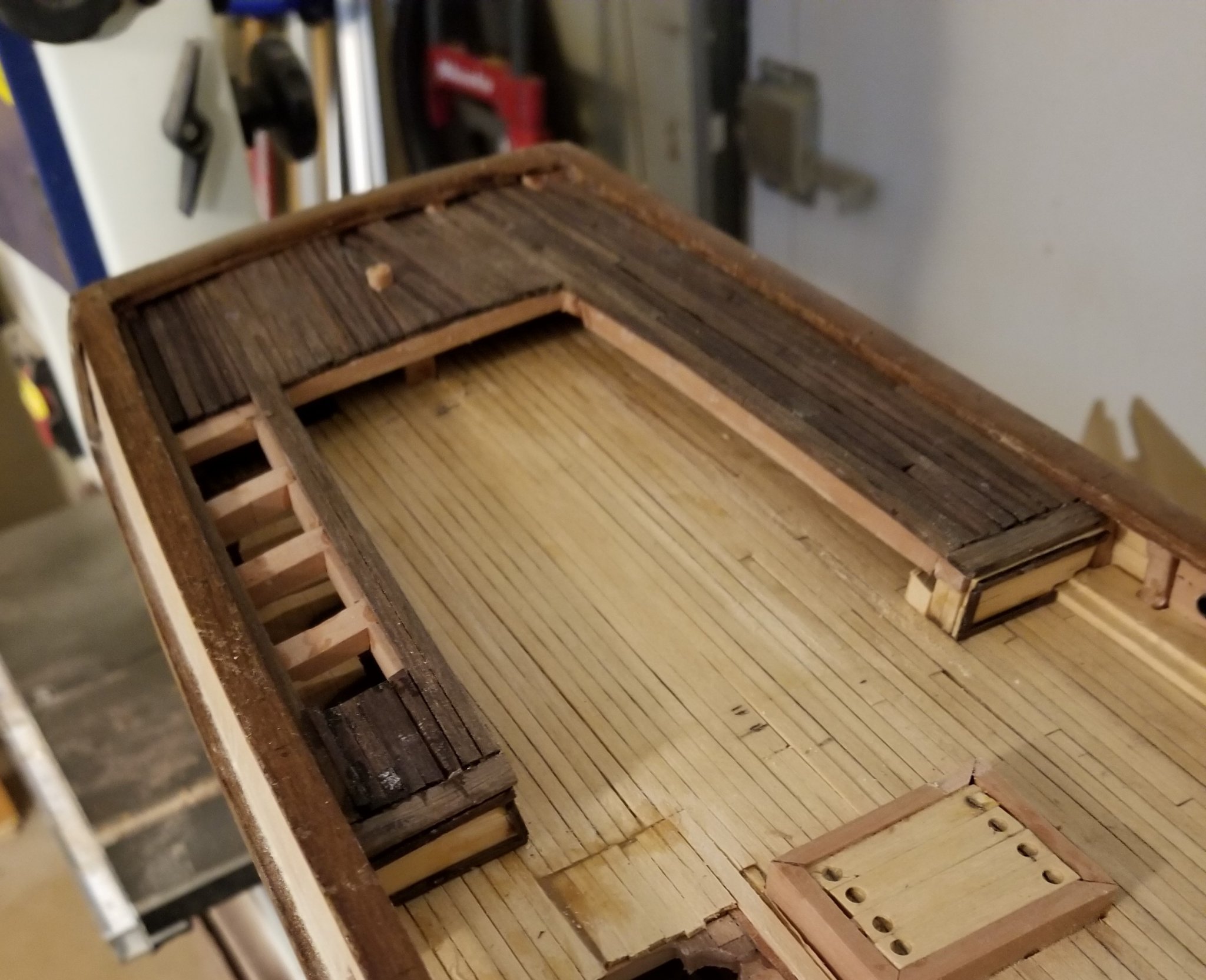
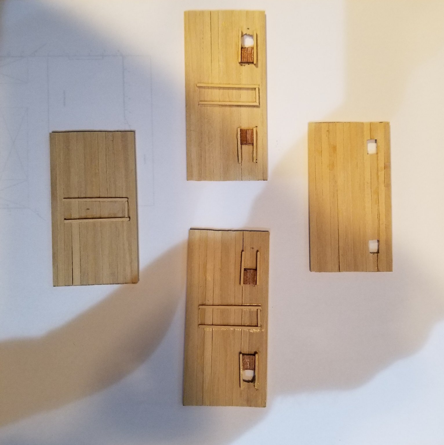
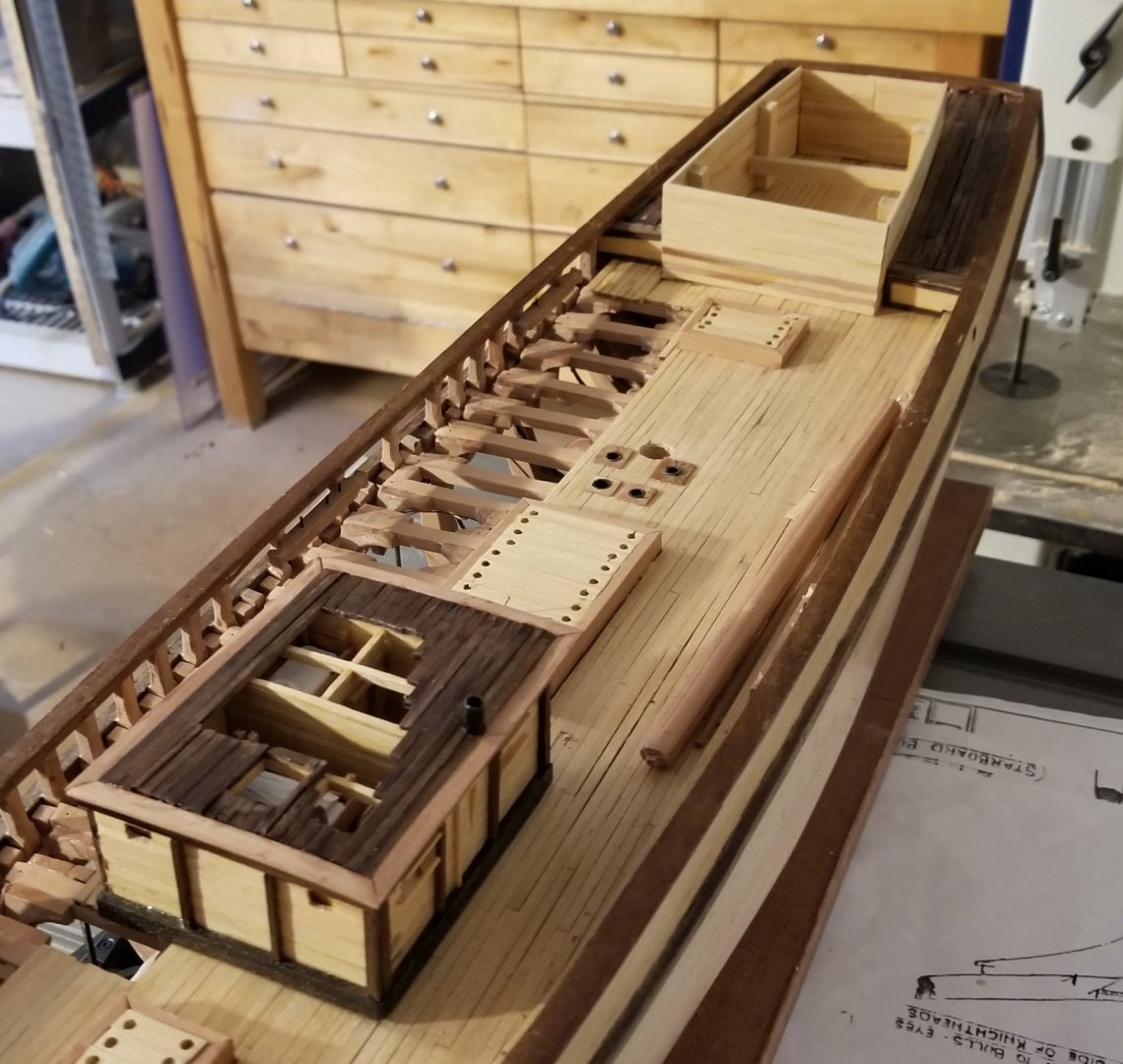
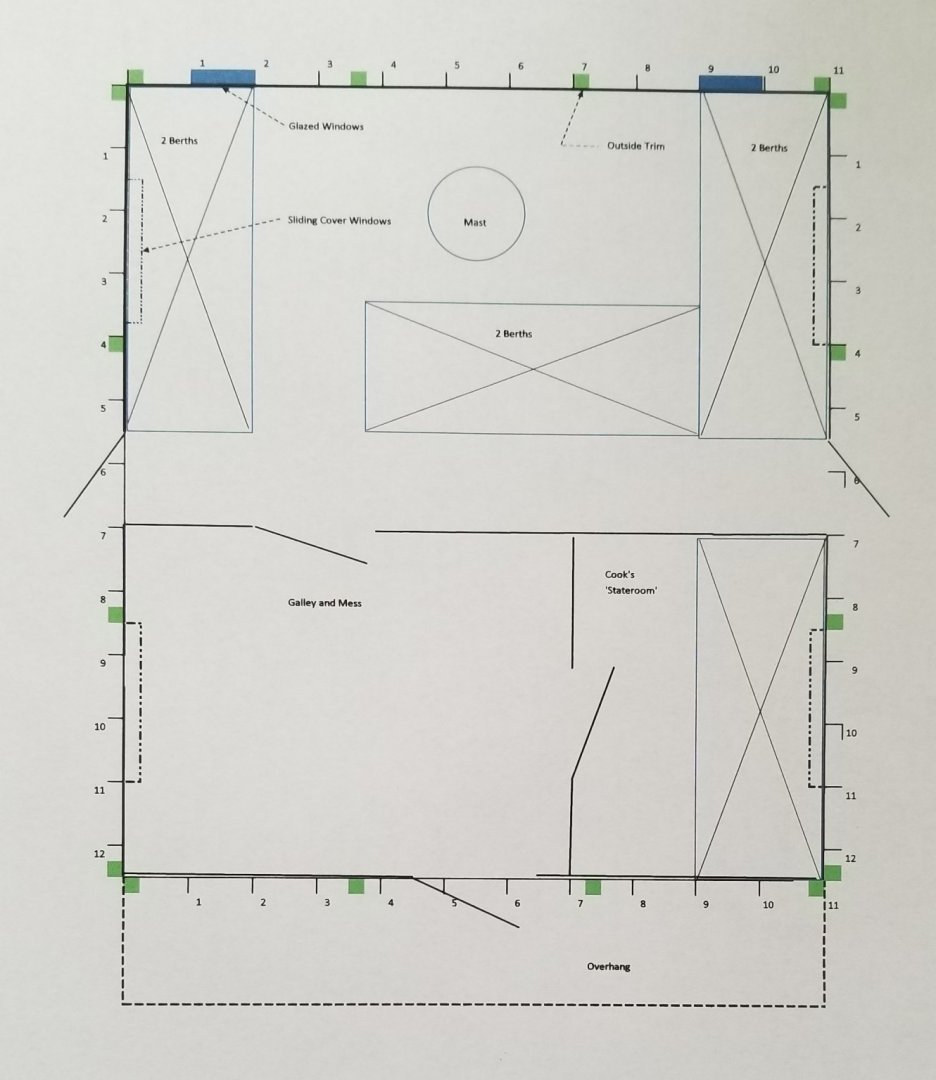
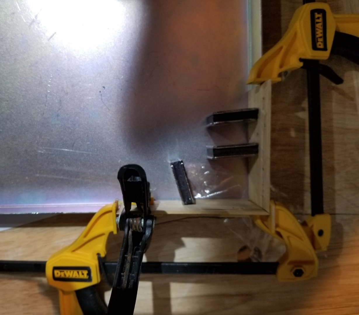
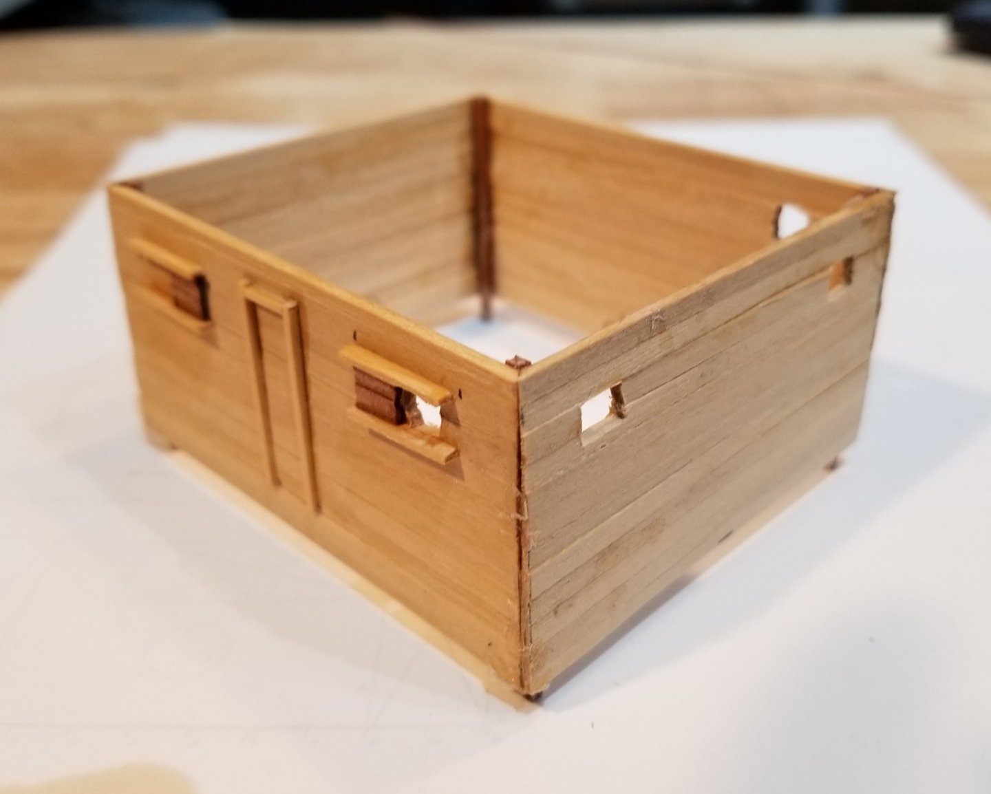
Now we tackle the main deck house. Many hours went into researching reasonable internals of the main deck house. The next photo shows the plan that I finally came up with. The beginning of the research was a thread called "Deck House versus Forecastle for Crew Quarters" where a number of folks discussed where the crew on Leon was most likely to have been quartered. I left this discussion leaning towards Deck House. One detail that needed settling was whether Leon had a Donkey Winch. If so, it would most likely have been in the aft portion of the deck house and reduced the living quarters significantly. Jeppe says that in all his research he never found a reference to a donkey winch on Leon. So we assume no winch. Another very important detail is the question of the existence of a companionway which would lead to a forecastle. Underhill shows one but remembering that his only primary source is the well known photo we see that even if there was a companionway it would not be visible in the photo because the bulwark would hide it. Using Crothers as a guide, the plan shown is proposed. It houses 6 crew and a cook. It honors the two very small windows in the forward bulkhead that are seen in the photo. There also appears to be what could be a door on the port bulkhead about one third the way aft. This would have been a very typical location for a door leading into the crew space. Underhill shows 2 doors in the after bulkhead but the plan shows only one because that seems to have been more common. The plan follows Underhill's 4 windows with sliding covers on the port and starboard bulkheads. So with the plan explained we can proceed to the construction. Horizontal planking - 1/16" x 1/8" (3" x 6") - is used for the bulkheads. The planks are edge glued. Following that, the doors and windows are indicated. The four exterior bulkheads are assembled in a steel jig that uses magnets to align surfaces in 90 degrees both in the horizontal plane and also the vertical plane. The four bulkheads joined together. . The two inner bulkheads have been added. The 12" high sill (almost black) can also be seen. This helps prevent sea water entering at the 3 external doors.


- 108 replies
-
- 3
-
-
- leon
- brigantine
- (and 1 more)
-
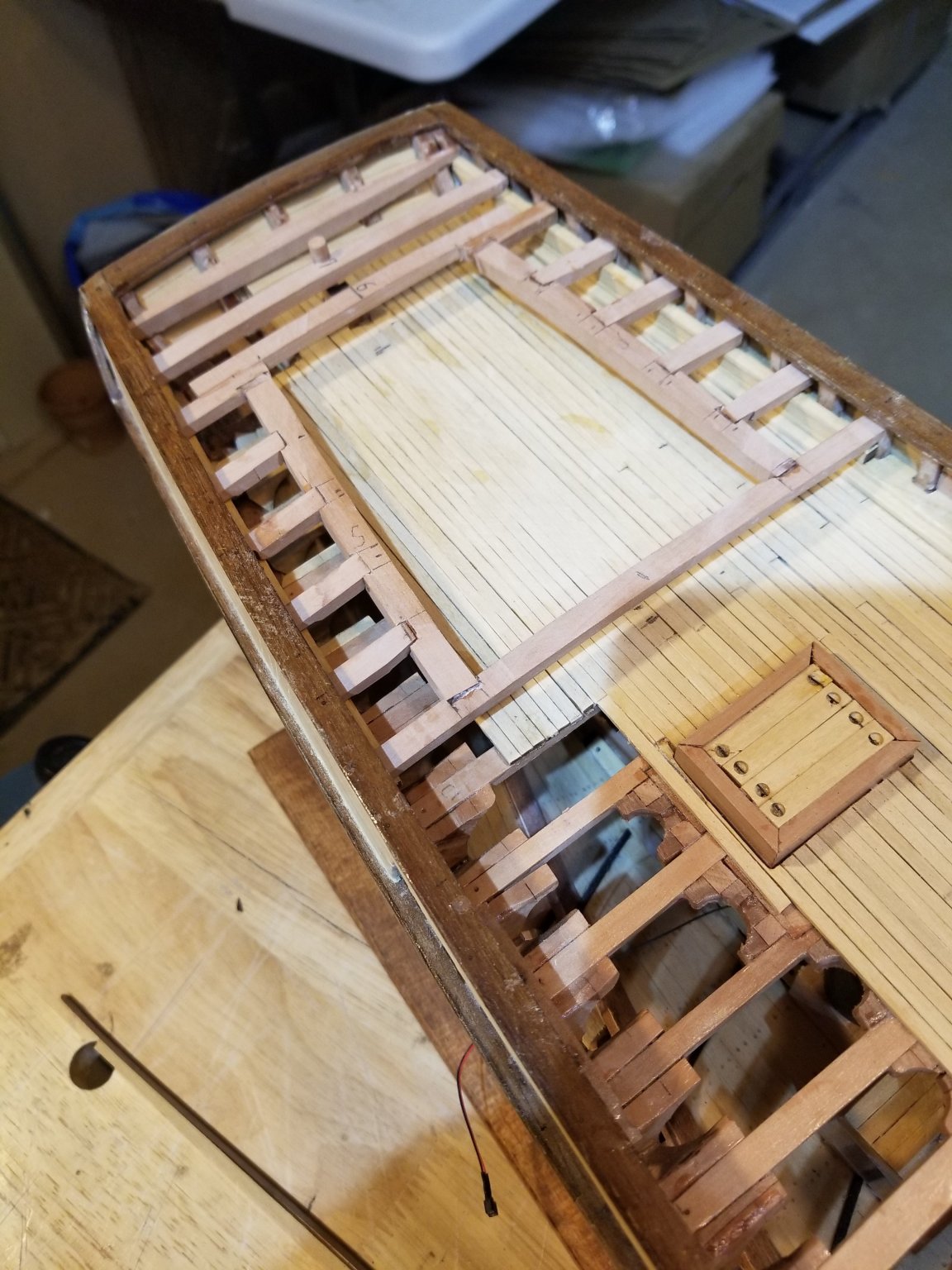
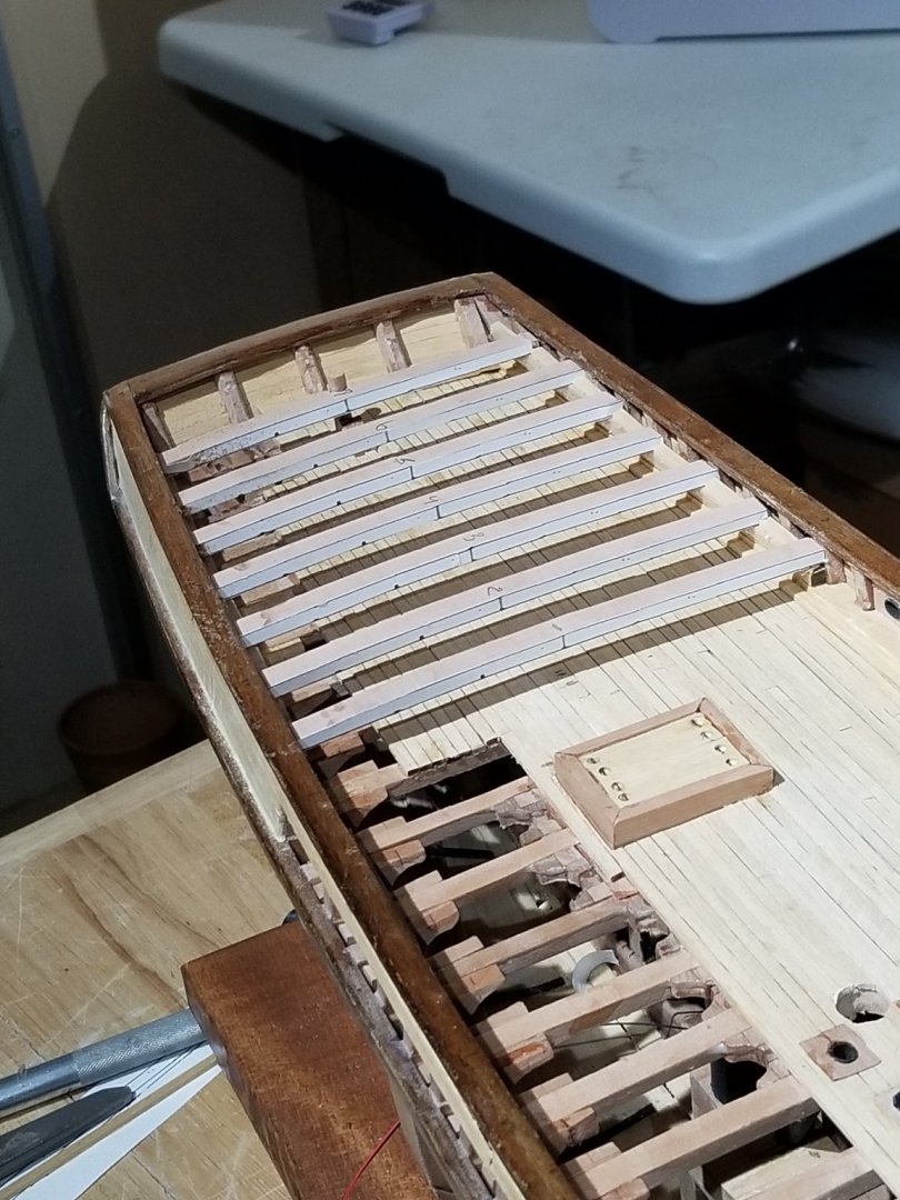
Now we'll build the quarterdeck. Most of the quarterdeck beams will be half beams but they all start as full beams. The camber of the quarterdeck beams is the same as the camber of the weather deck. Most of the beams are cut out to receive the aft deck house. The forward most beam will be cut out as the last step as it provides temporary strength to the deck structure. The quarterdeck planked with Indian Rosewood, like the anchor deck, with a number of starboard planks left off. We'll come back to here after we have built the aft deck house. But first we design and build the main deck house.....
- 108 replies
-
- 4
-
-
- leon
- brigantine
- (and 1 more)
-
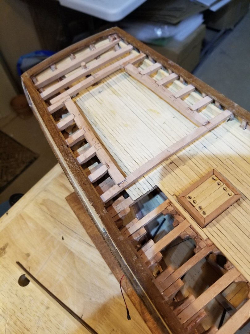
Now that the anchor windlass is in place we can install the anchor deck. I haven't found the scantlings of an anchor deck anywhere but on a few drawings they seem to be the same as for the weather deck. This was a surprise to me since I expected the scantlings to be lighter. The final answer that I settled on, came from a single sentence in the DNV Rules for Wooden Ships (1970, page 30) where it says "Scantlings in Raised Quarterdeck should be as for Main Deck." Carrying this logic forward to the anchor deck provides our selected answer. BTW, we reference the 1970 Rules because an English translation was readily available. The anchor deck beams are shown in the next photo. The two diagonal pieces support the aft edge of the deck planks as well as the cat-heads. The anchor deck is planked with Indian Rosewood not for authenticity but to match the roofs of the main deck house and the aft deck house. My designer daughter, Katie, has been calling the color shots from the beginning. A little bit of the anchor deck beams are exposed in the spirit of maximum visibility. The deck planks fit snugly underneath the main rail so that the main rail serves as a covering board for the deck and the bulwark planking. We add the tapered cat-heads. Later we will install 2 sheaves at the end of the cat-heads as well as some iron work simulating the whisker booms. Now we return briefly to the Lumber Hatch (Report Post #58). The outline of the hatch was a very poorly executed item. Frank / Mahuna (Report Post #59) suggests a way of improving the item. He suggested using Scenic Glue mixed with same wood dust. It made things a little better so thank you Frank / Mahuna. So here is before and ..... ..... here is after - not great but a little less jarring.


- 108 replies
-
- 4
-
-
- leon
- brigantine
- (and 1 more)
-
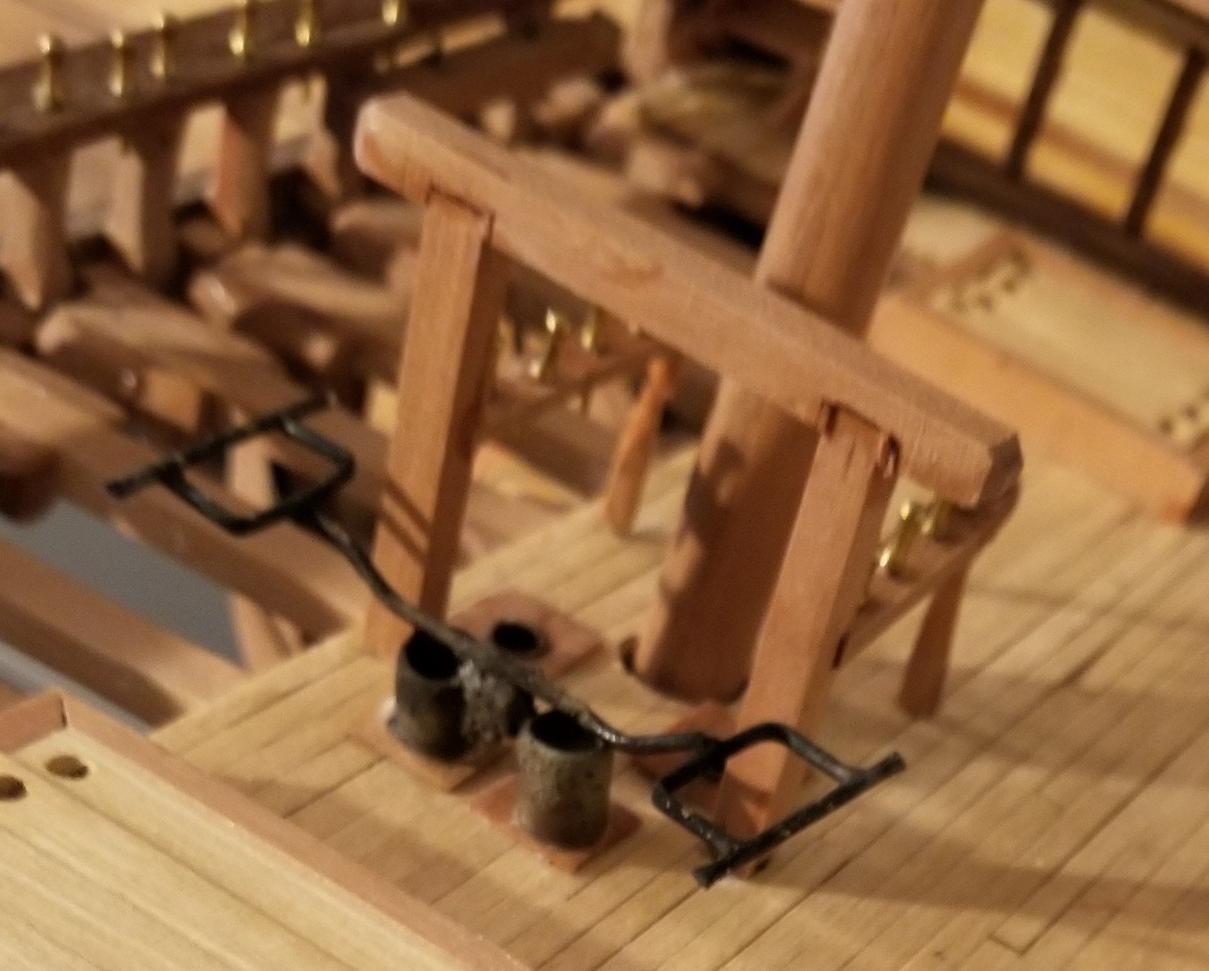
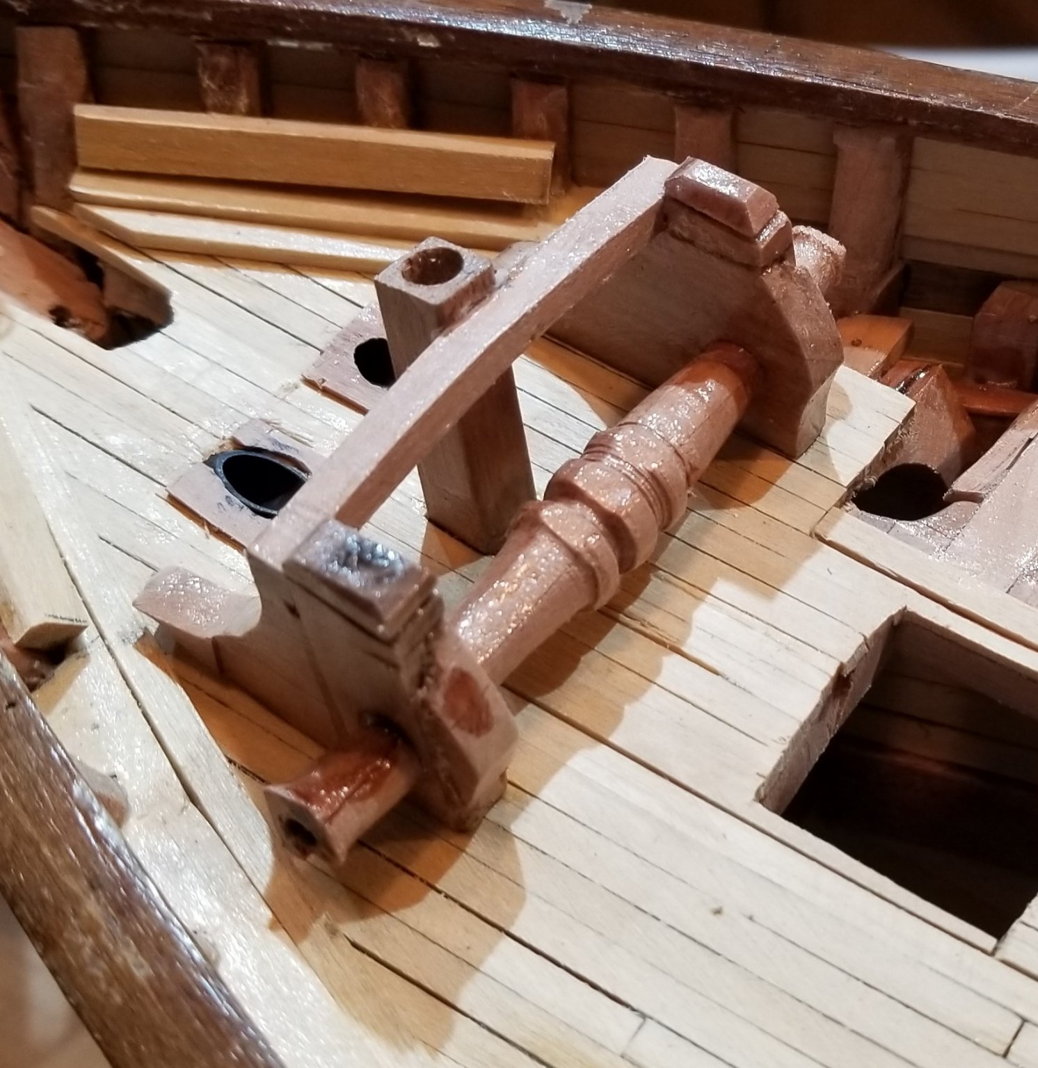
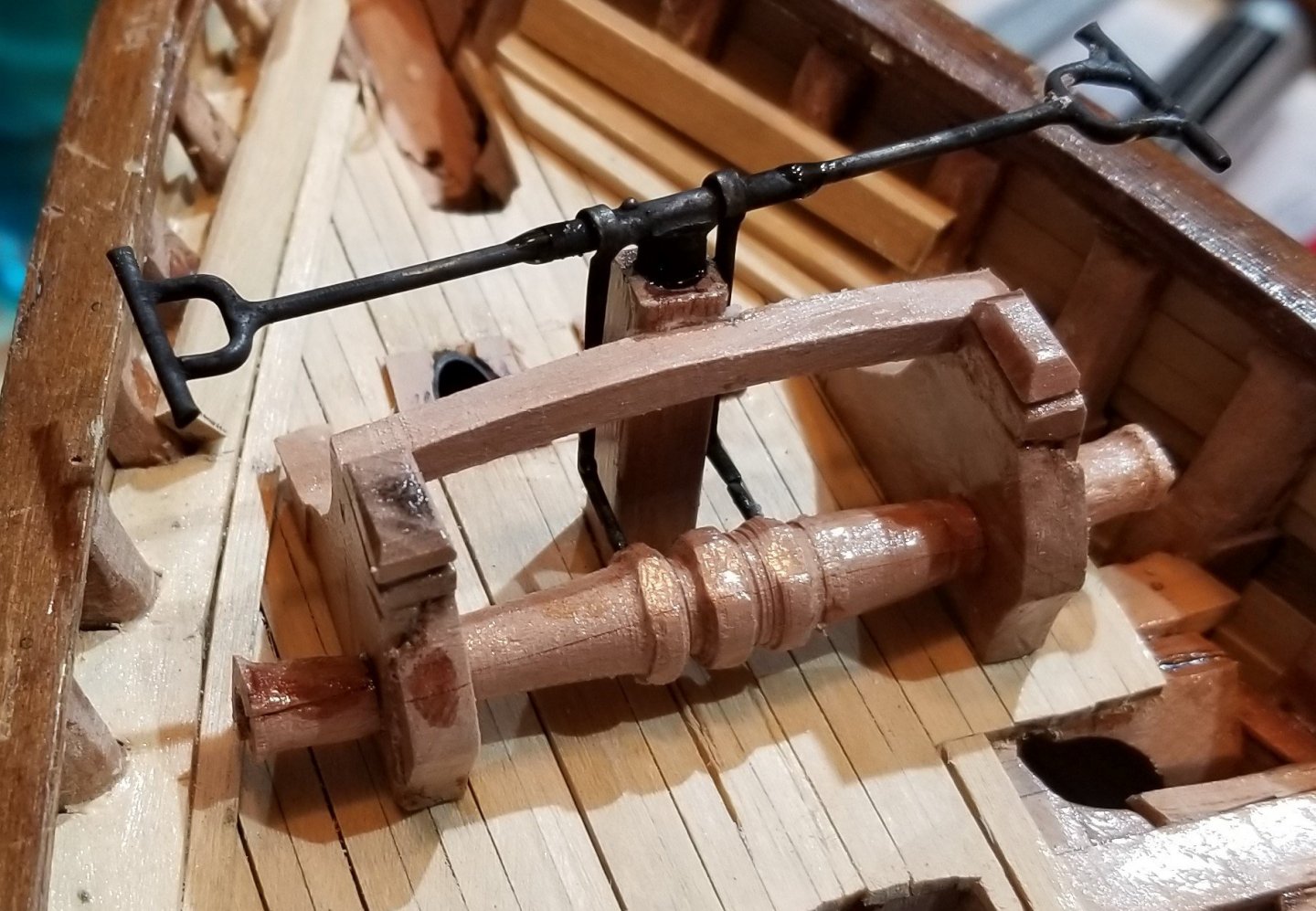
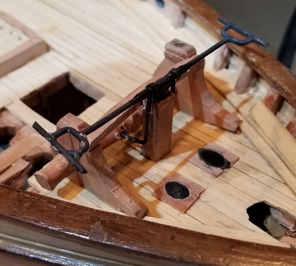
This is a particularly critical posting - covering the anchor windlass - because I used my tiny DIY woodworking lathe for the first time (in fact, first time using any lathe!) AND this is also my first time using silver soldering. The pawl bitt has been installed for a long time and now it will support the strong back of the windlass.. The cheeks and standard knees are glued to the deck planking. The carrick bitts are also glued to the deck planking although they should have been carried down through the deck and bolted to a deck beam. The iron work is then installed. Typically, the hand lever is not shown in a model (but I decided to include it to make it a little clearer how this windlass actually works). I believe that installing this item now will not make future forward items more difficult to install. The two vertical rods, the purchase rods, transfers the turning force from the hand lever down to the purchase rims, the two outside rings on the windlass barrel. The center ring on the barrel is the pawl rim and prevents the windlass from reversing direction as the pawl from the pawl bitt engages the pawl rim. This last shot faces aft. I want to show the same kind of hardware on the bilge pumps but there the handles may interfere with the installation of other items.

- 108 replies
-
- 7
-
-
- leon
- brigantine
- (and 1 more)
-
Brigantine Leon by Beckmann - 1/48
Doug McKenzie replied to Beckmann's topic in - Build logs for subjects built 1851 - 1900
Beekmann, I do not know why it has taken me so long to notice that you did not put a companionway aft of the anchor winch and forward of the forward hatch as Underhill shows. I assume this means you don't believe that Leon had a fo'c'sle. I tend towards that same conclusion and I'm very curious as to how you came to that conclusion. I love your pictures! Thanks and I hope all is well with you, Doug -
Michael, Thanks very much for your comments. Bear in mind that I consider this question to be unresolved. But we do know some stuff that makes the question interesting. We know that Leon had a crew of 8 when she was finished in 1915. If maybe 3 of these were in the after house then the deck house would house 5. I've seen a few deck house plans the same size as Leon's that house 5 crew. Another point is that it is commonly believed that Leon was cut down to a schooner rig in her later years. We now know this is not the case and she ended her life as a brigantine. The confusion arises because of the Norwegian words for brigantine and schooner. I mention this because if she had a crew of 8 as a schooner she probably had one or two more as a brigantine. But since she was always a brigantine, we can say that her crew was 8. An important point that you make is in regard to the companion way. Underhill shows a companion way clearly and unambiguously in the plans. The problem is that Underhill only had access to the well known photo taken about 30 degrees forward of the port beam. The companionway, if one existed, would not be visible in this photo as the bulwark would hide it if Underhill's height was correct. To make matters worse, Underhill refers to the 'little fo'c'sle' - where he comes up with this diminutive we'll never know. In any event, I actually built a fo'c'sle with 5 bunks in the model. But then I realized that it's not a sure thing and I took it out - my wife says I just wanted to model a fo'c'sle so that's why I let myself believe that there really was one. By the way, I should mention that the 1880 sheer plan shows no evidence of either a companionway or a fo'c'sle whereas it does show hatches and houses and the pawl bitt and the lumber hatch! So my final solution is a little silly because it is self inconsistent - I kept the companionway as sort of a tribute to Underhill but there is no fo'c'sle and the crew quarters will be in the deck house which I haven't built yet. So there it is - a bunch of information, that in my opinion, leads to no sure conclusion. Doug
- 108 replies
-
- 1
-
-
- leon
- brigantine
- (and 1 more)
-
Frank and Sailor1234567890 Frank - Thank you very much - I'm getting some of that glue that you recommend and will use it with sawdust from a sander.. If it works nicely I'll try to use an xacto knife to scratch out another rectangle that is less gross.. Sailor1234567890 - Thanks for the correct names I particularly like Navel Pipes. I'll edit my post. As far as the shape and position of the lumber hatch, I am following an 1880 sheer plan of Leon so maybe Leon is just different from most (as her diagonal hanging knees are).
- 108 replies
-
- 1
-
-
- leon
- brigantine
- (and 1 more)
-
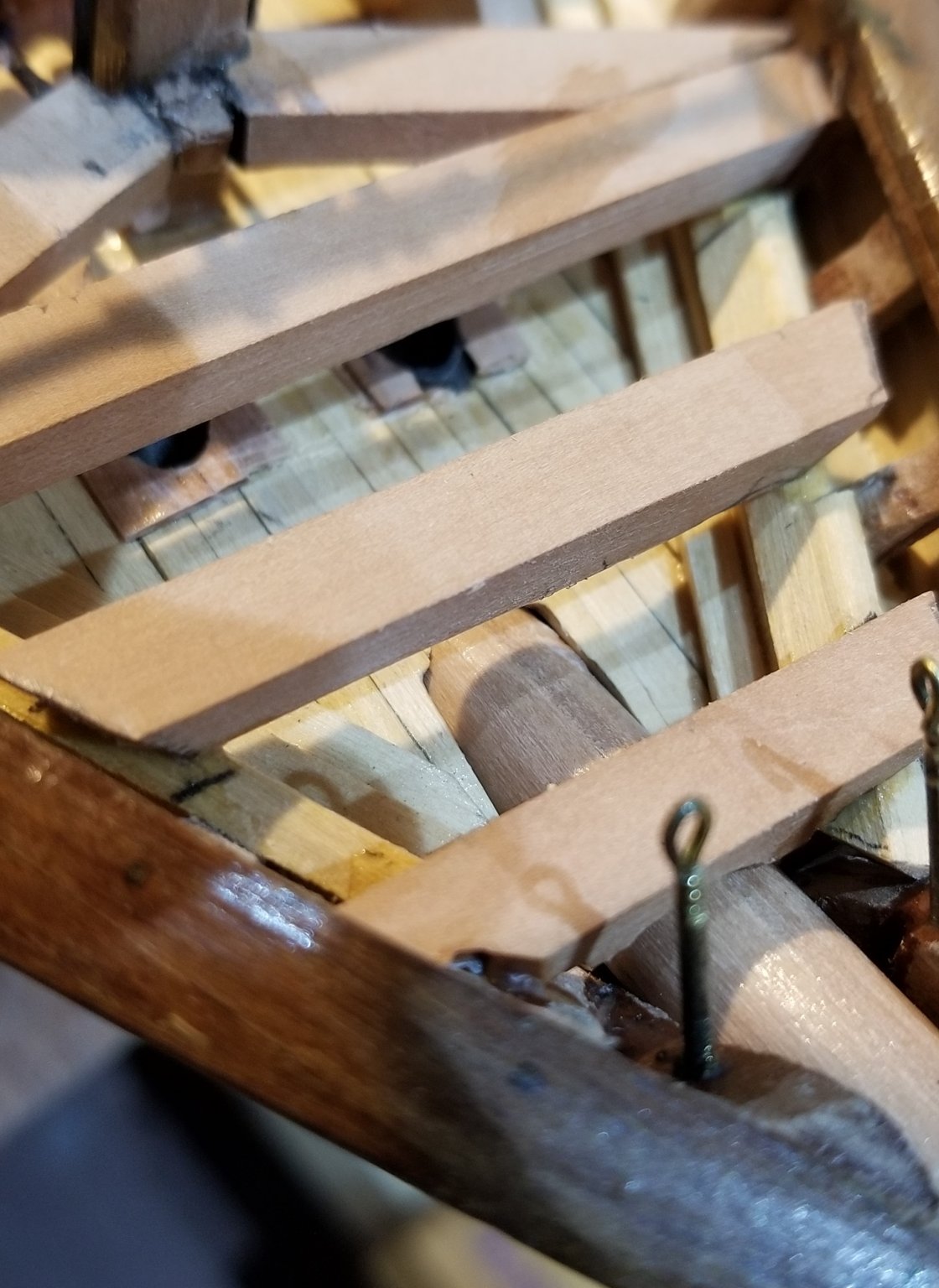
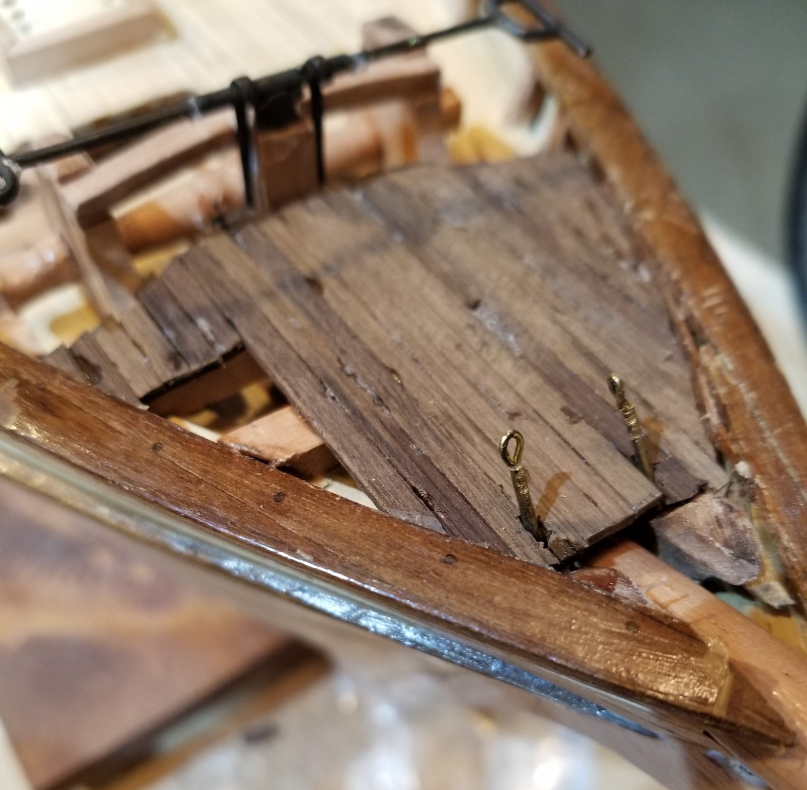
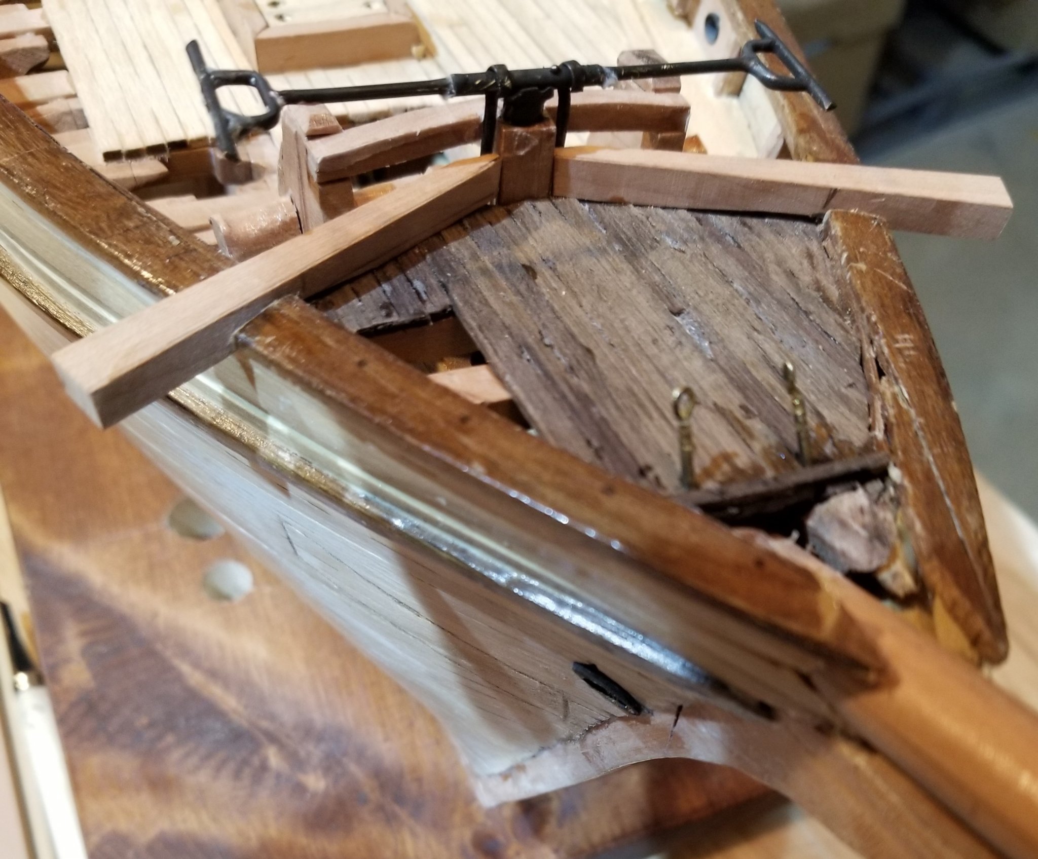
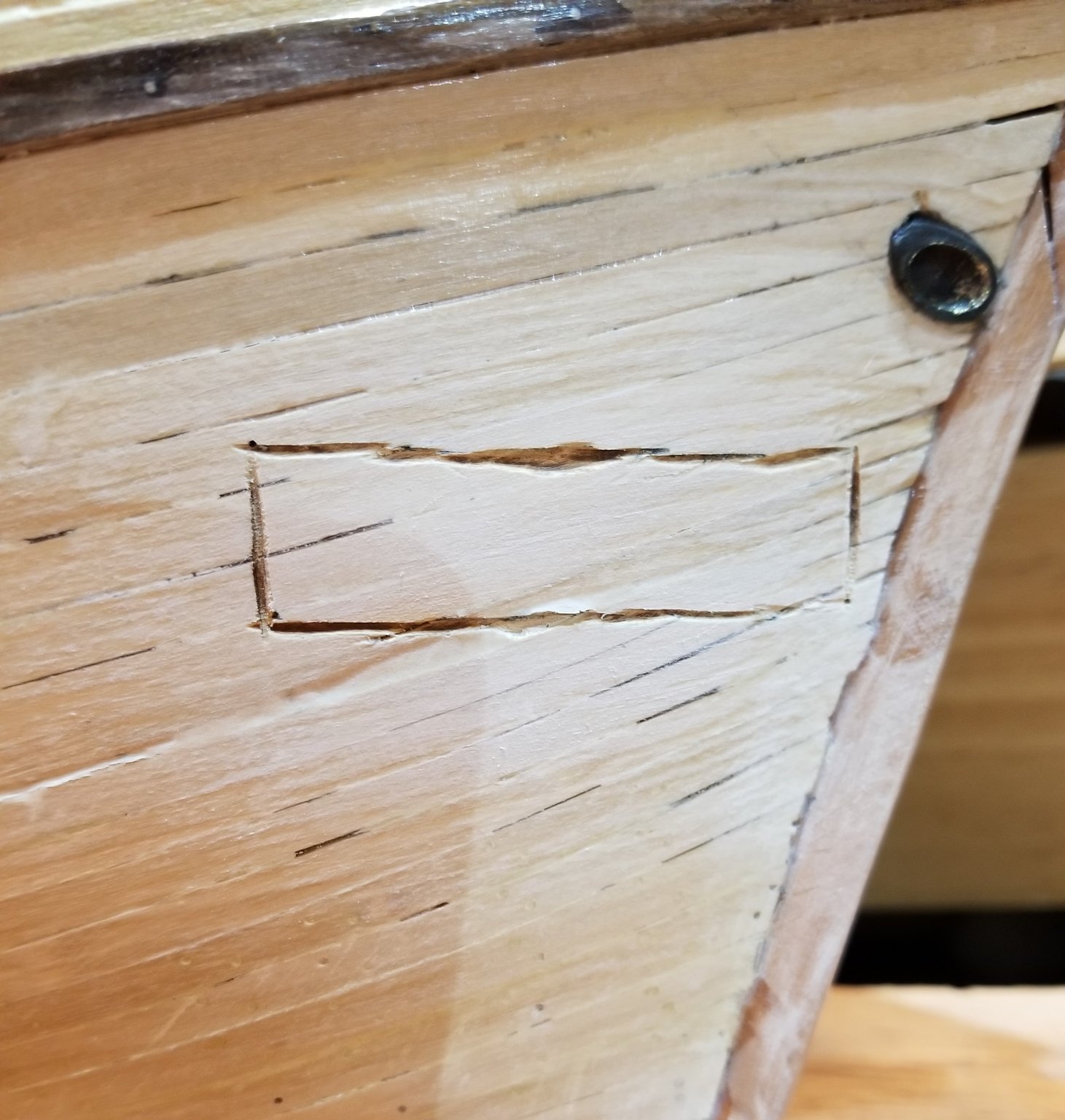
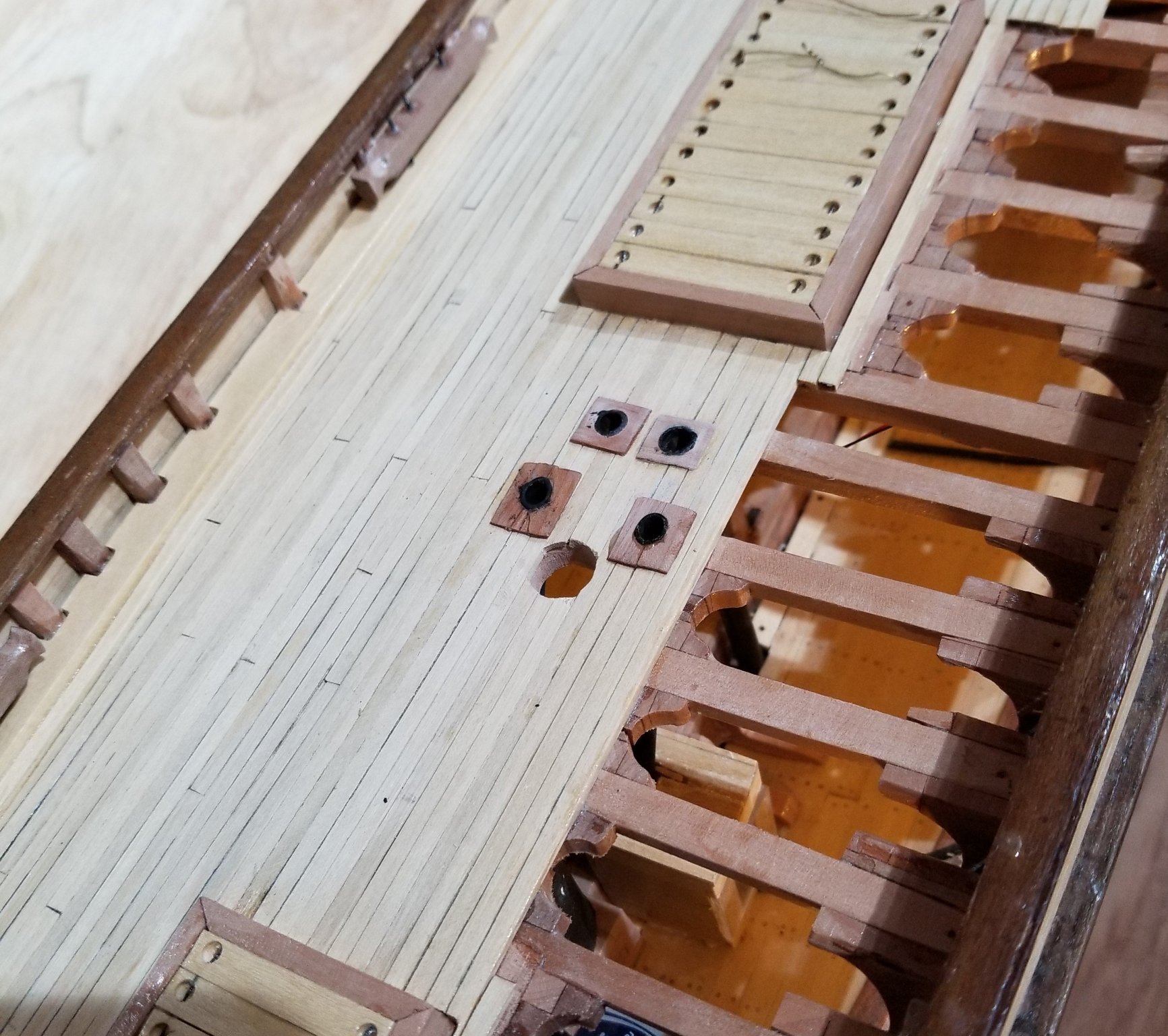
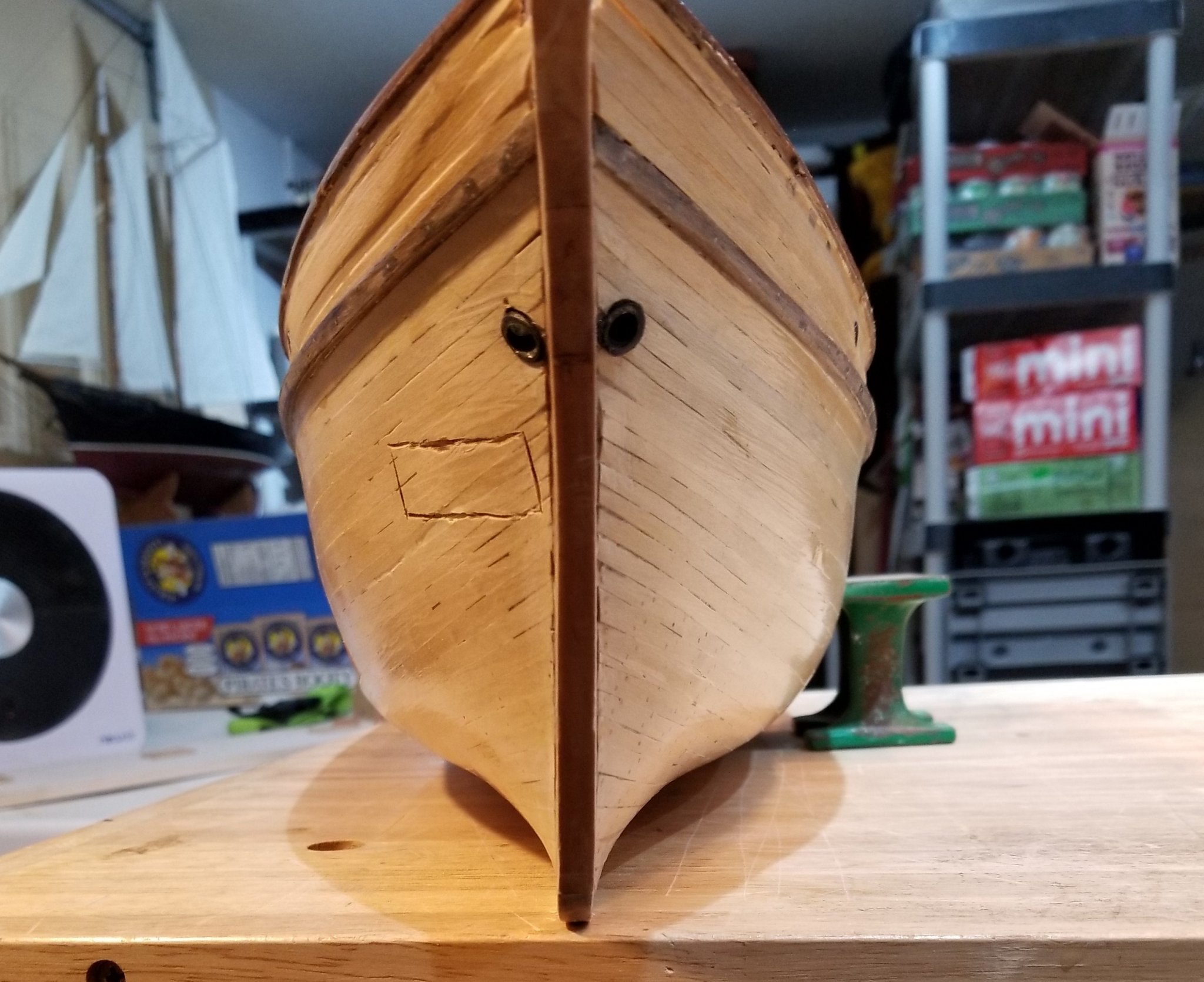
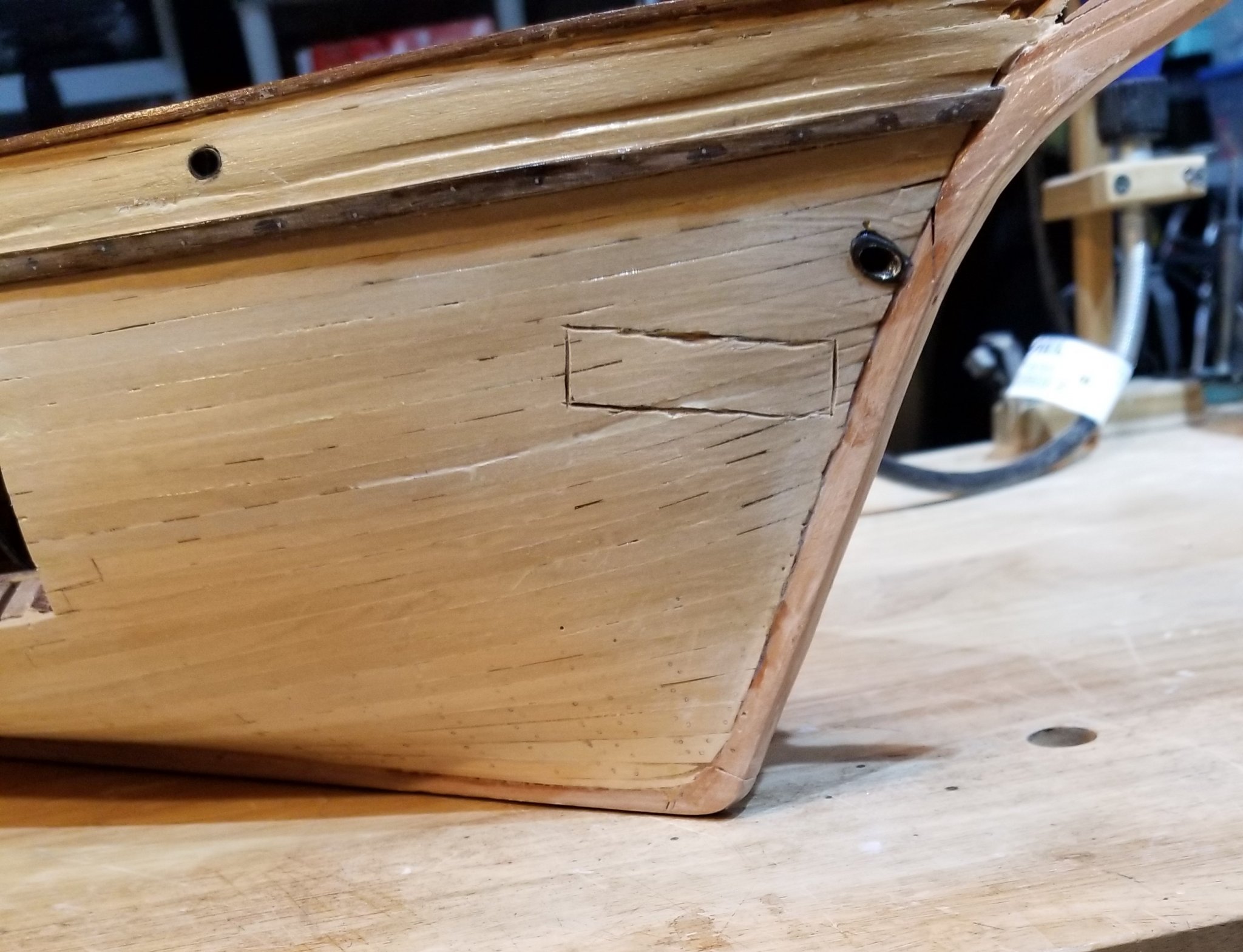
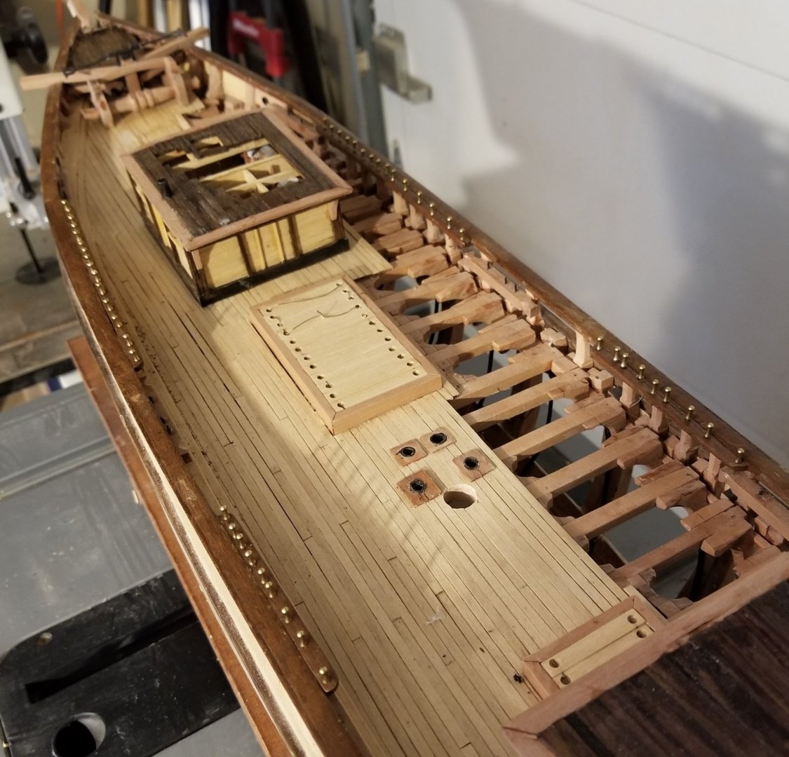
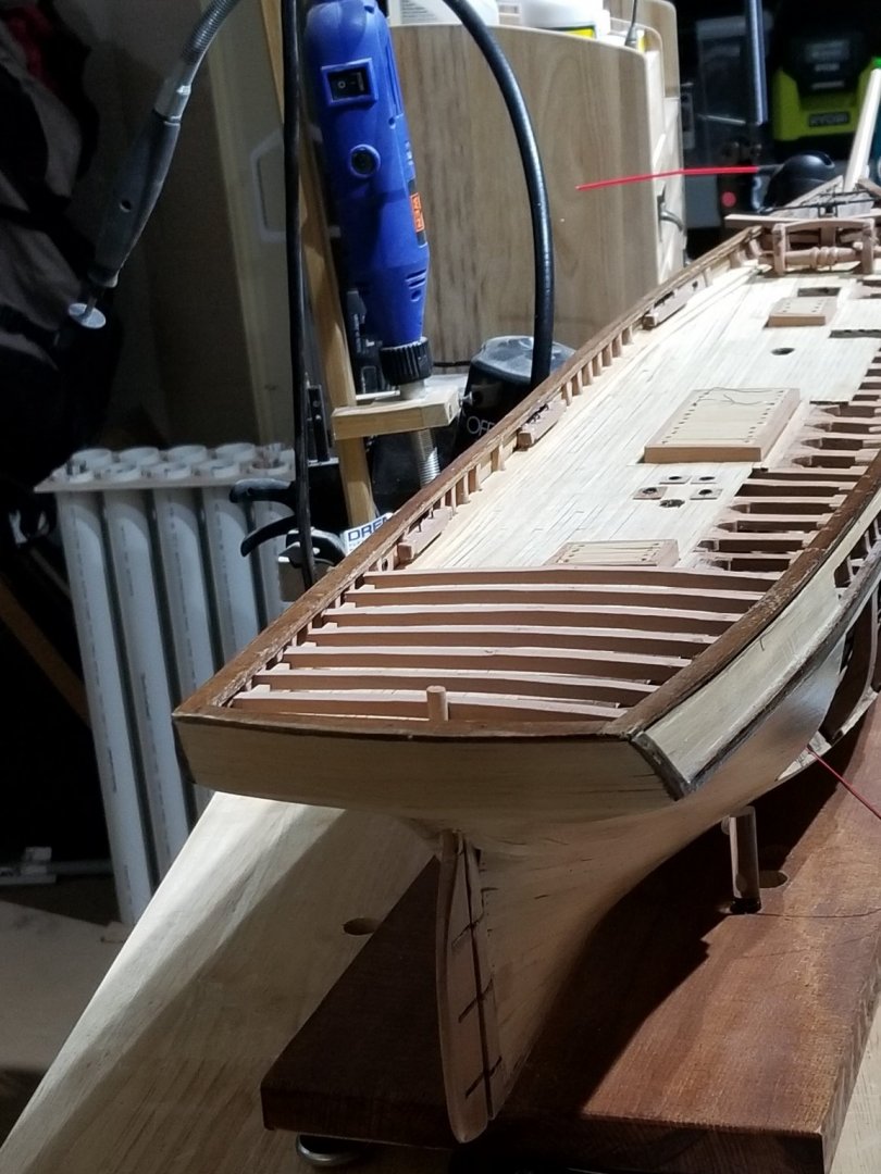
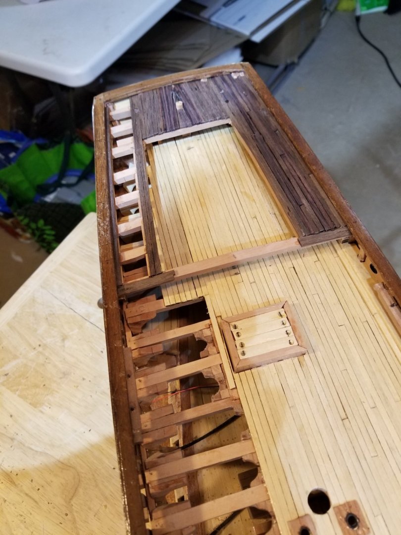
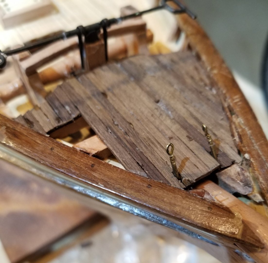
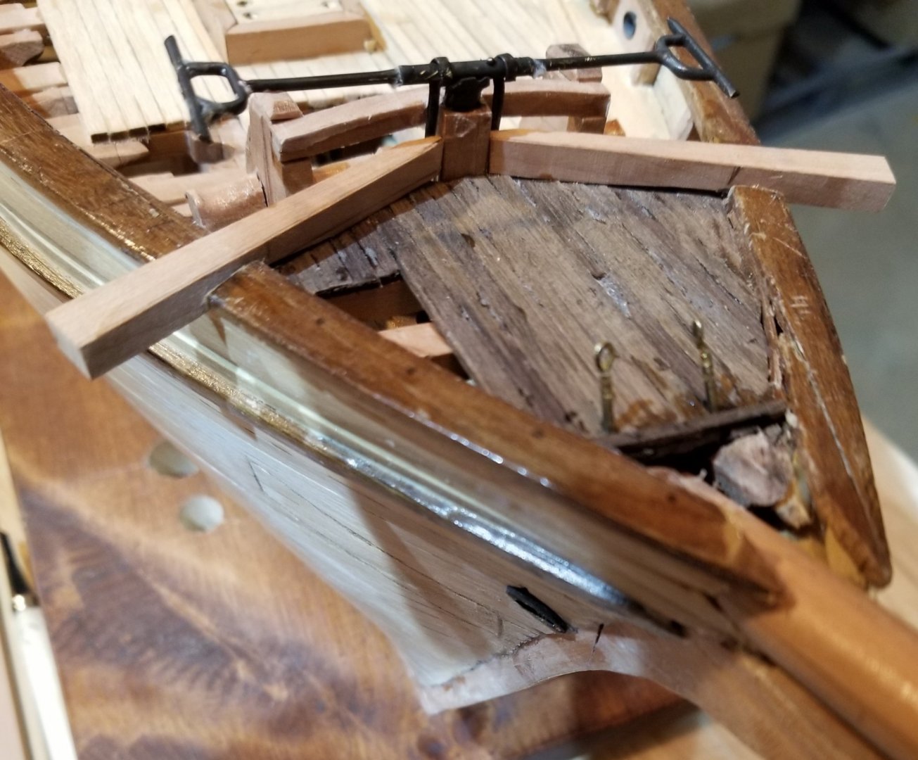
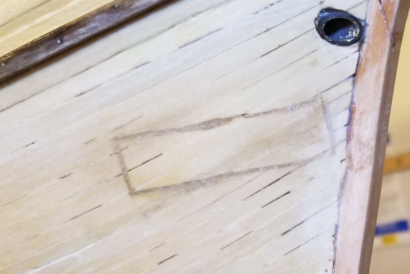
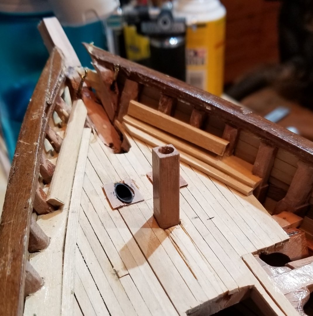
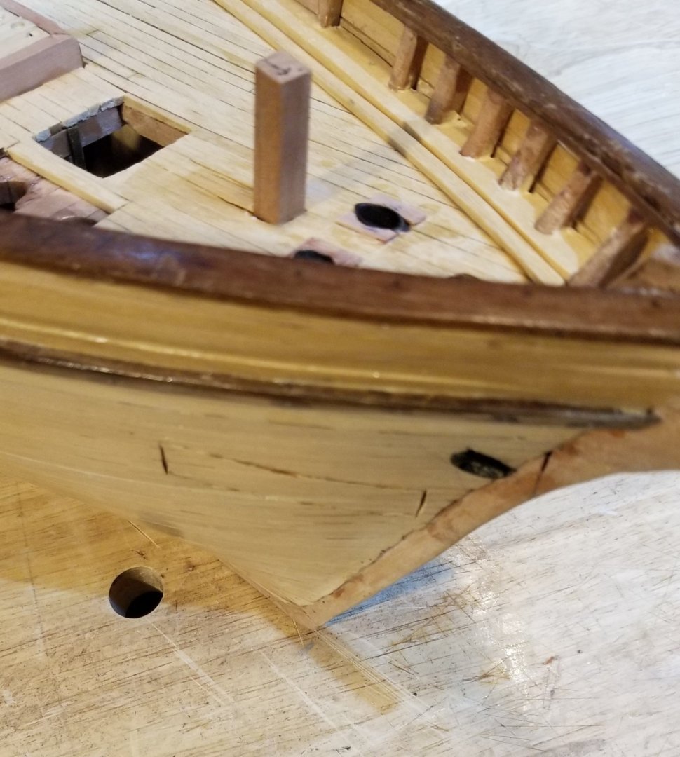
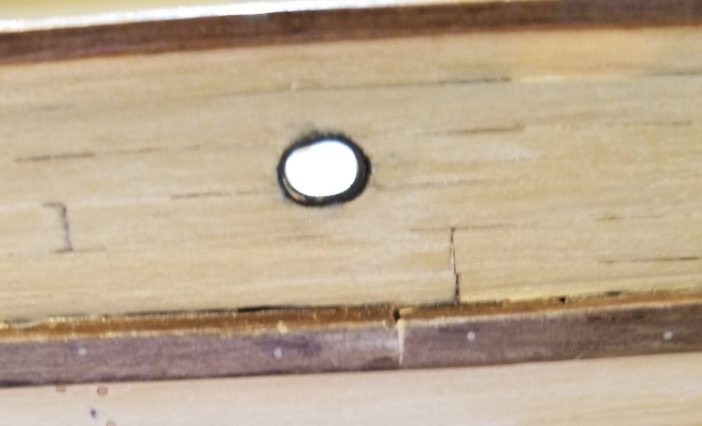
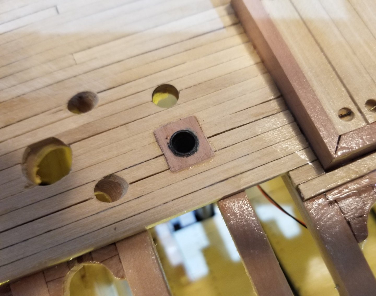
All the 'pipe' work is now done i.e. the port bilge pump pipe, both the navel pipes (the pipes that lead the anchor chain down from the deck to the top of the anchor chain lockers. aka chain pipes) and both hawse pipes. The picture below shows the bilge pump pipes and the navel pipes. The relatively steep slope of the navel pipes facilitates the smooth movement of the chain when it comes up on deck. The next picture shows the deck plates where the pipes come through the deck. These are 1" thick plates which scale down to about 1/64" To work with these thin pieces of wood I flooded one side with super thin CA to provide some strength. This permitted the 3/16" holes to be drilled as well as making it possible to enlarge the drilled holes with round files without splitting the wood.. For reasons, that I do not understand, the hawse pipes leave the hull about 2’ forward of where they should, so they actually touch the stem. This occurred during filing rather than the drilling of the holes but I didn't notice it until it was too late. I don’t see any way to fix this so the mistake will just stay with the model. The hull flange was formed with two brass tubes telescoping around the main tube. The main tube is 10” in diameter. I used soft solder since I still haven’t bitten the silver solder bullet. The angles both at the hull and deck were obtained by using the vertical belt sander and seemingly a never-ending progression of Does it fit? No, sand a little more. Repeat. The process was so inelegant that I haven’t bothered to show any photos of the process. I was pleased that from the bow, the two hawse pipes at least look as if they are nearly mirror images. On the deck, the hawse pipes end in deck plates that are 1” thick just like the deck plates on the bilge pump pipes. In all three pictures, the lumber hatch, the 2’ x 8’ rectangle, is clearly seen just above the water line. The scratched outline is supposed to represent the closed lumber hatch which I’ve been told is practically invisible on a real ship. A poor job was done here and I do not know how to make it look better so I guess that, like the horizontal position of the hawse pipe, it will just stay with the model. Any thoughts on how to clean this up would be most appreciated.


- 108 replies
-
- 3
-
-
- leon
- brigantine
- (and 1 more)
-
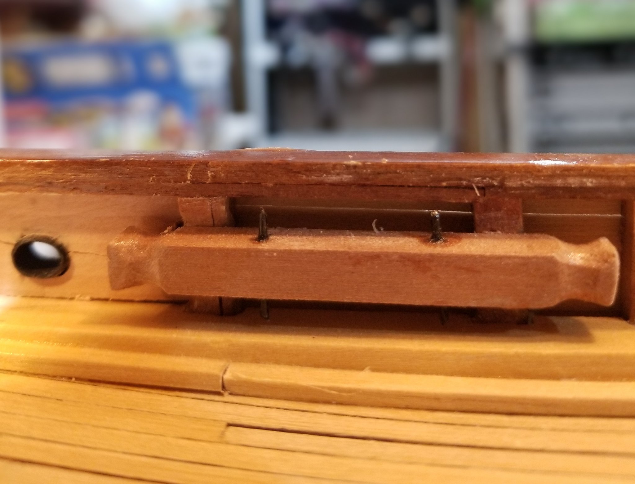
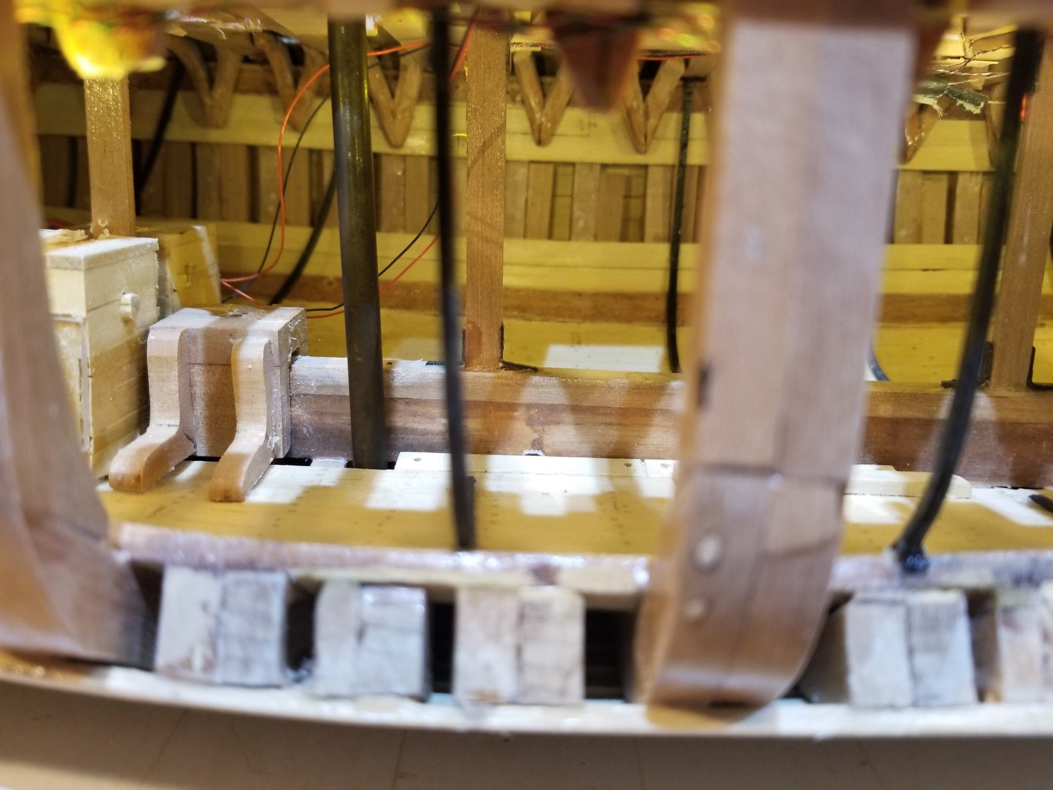
The 6 kevels (aka but rarely used, cavel, cavil) have been installed with one mooring port. A kevel is a large, generally horizontal timber bolted to two adjacent bulwark stanchions providing a very strong belaying point for large lines such as mooring lines. On Leon this is 9" x 9" following Underhill. You can see the two iron pins (1 1/2" diameter) which could be used for smaller mooring lines and in some cases running rigging. To the left of the kevel is an inboard view of a mooring port. I'm probably going to model a mooring line to show how the kevel is actually used. Underhill shows 6 kevels in his plans. I understand the 2 at the bow and the two towards the stern but I do not understand the 2 at midships. There is not even mooring ports for them. Oh well, I included them regardless. The inboard view of the mooring port also shows the wooden chock inserted between the adjacent bulwark stanchion to ensure that the thin bulwark planking does not fail under strain. The outboard view of the mooring port, in the next picture, shows the results of two techniques from Underhill. The first is to let the thickness of the brass tubing serve as the flange of the port. The second is to make the port first from brass tubing and then fashion the hole in the wood to fit the port. The second is 'obvious' but I needed to be told! In the picture below, the starboard blackened bilge pump pipe is shown descending from the deck into the bilge. The next picture shows the treatment of the bilge pump pipe on the deck. I tried to find authentic material on the 'flange' but Tosti's Young America was the only one I found so I more or less followed his.


- 108 replies
-
- 3
-
-
- leon
- brigantine
- (and 1 more)
-
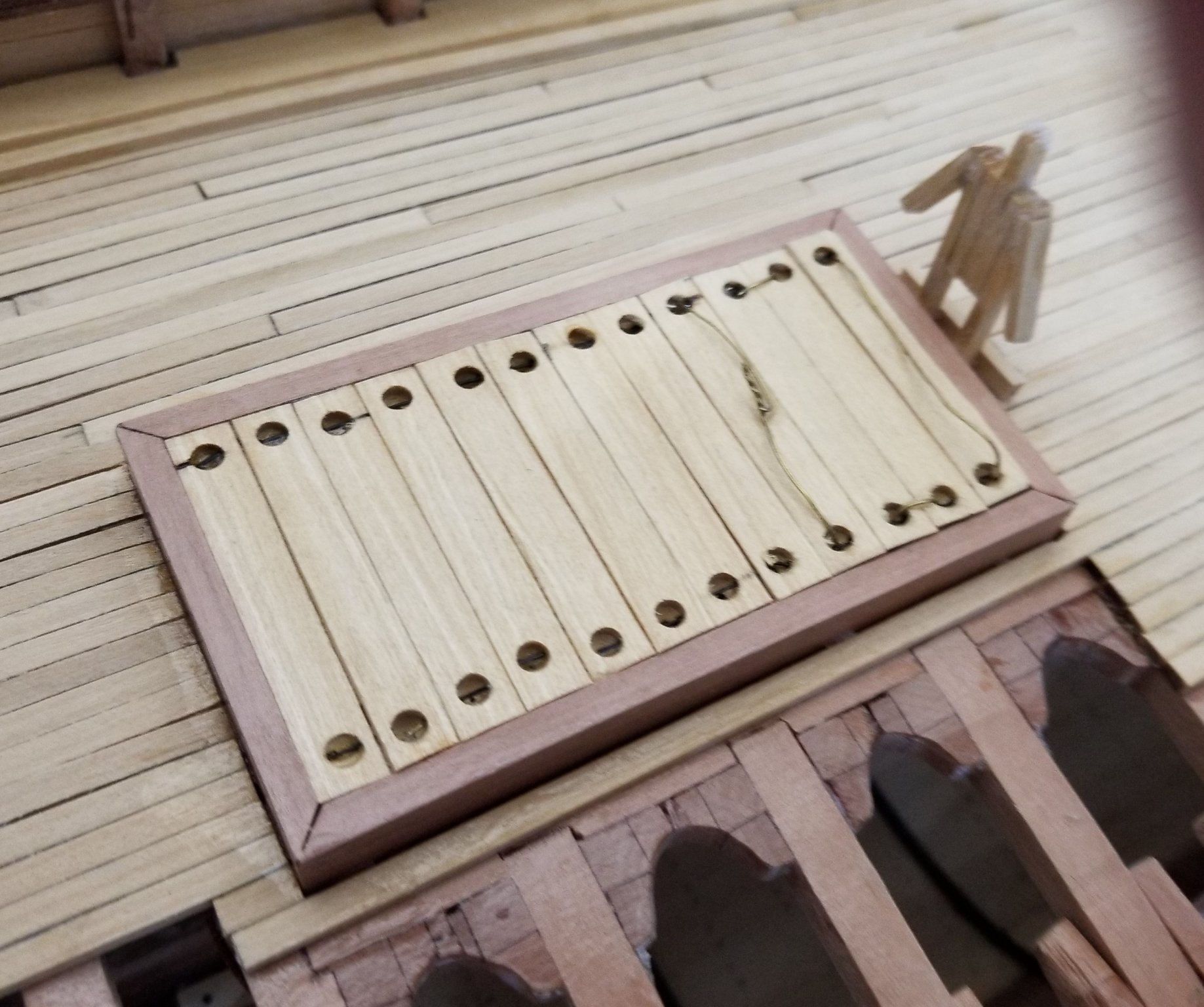
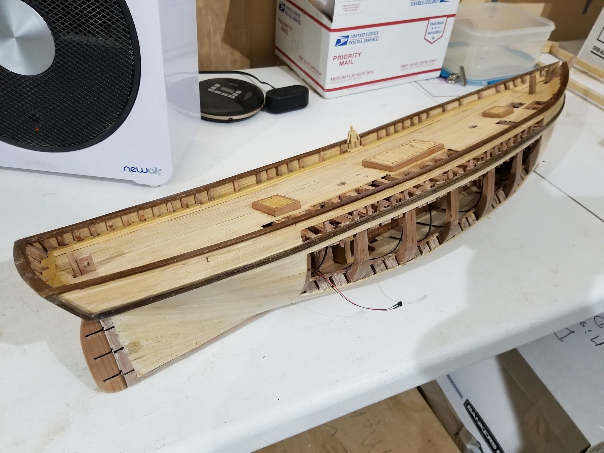
Here is the completed main hatch. A member of the crew (5' tall) helps to understand the scale. The last 4 hatch covers (nearest the crew member) are wired together and not glued in place because I'm thinking of leaving 2 or 3 or 4 covers off in the spirit of maximum visibility, but I haven't decided yet. This photo shows all three hatches completed along with the completed rudder and the pawl bitt (in the bow). I used plastic striping for the pintles and gudgeons. Since that provides no strength, I pinned the rudder to the stern post at the lowest pintle / gudgeon pair. The fine wire (red and black) ends in a connector that allows the battery and the switch for the lights to be left off the ship except when being used. Before framing the quarter deck and anchor deck, Underhill recommends fitting the cavels, the hawse pipes, the eyes for the forestay. I also want to make a correction at this time. The bulwark planking for the quarter deck is supposed to be thicker then the bulwark planking in the waist creating a slight ledge which is actually quite visible. I need to double plank the quarter deck bulwark to achieve this effect.


- 108 replies
-
- 3
-
-
- leon
- brigantine
- (and 1 more)