HOLIDAY DONATION DRIVE - SUPPORT MSW - DO YOUR PART TO KEEP THIS GREAT FORUM GOING! (89 donations so far out of 49,000 members - C'mon guys!)
×


Doug McKenzie
-
Posts
221 -
Joined
-
Last visited
Content Type
Profiles
Forums
Gallery
Events
Everything posted by Doug McKenzie
-
Allan, This is one of the more creative suggestions that I've seen. Unfortunately, I have already selected my 'unusual' modelling task - a Norwegian Windmill Pump (see photo). For several years I was afraid I wouldn't be able to model this thing on Brigantine Leon because I was pretty sure that it would only have been installed after she had been cut down to a schooner rig. Recently, however, I have learned that Leon was never cut down to a schooner rig and therefore she had the windmill pump as a brigantine. I'm going to model it so that it can be removed and displayed along side the ship since it is pretty dramatic!. Thanks for an excellent competing suggestion, though. Doug
-
John, Thanks I didn't want to do something and have some one say "that's not the way they did it," So thanks again! Doug
-
I am building a 1 to 48 scale model of the Briganteen Leon with much of the interior visible I would like to leave off some of the hatch covers from the main hatch but I do not know where to stack the ones I remove. If we imagine that they want to take a look see into the hold they might just remove 3 covers. Would they stack them on top of the covers not removed or on the deck next to the hatch. Silly question I know but i have no experience with these hatches. Thanks
-
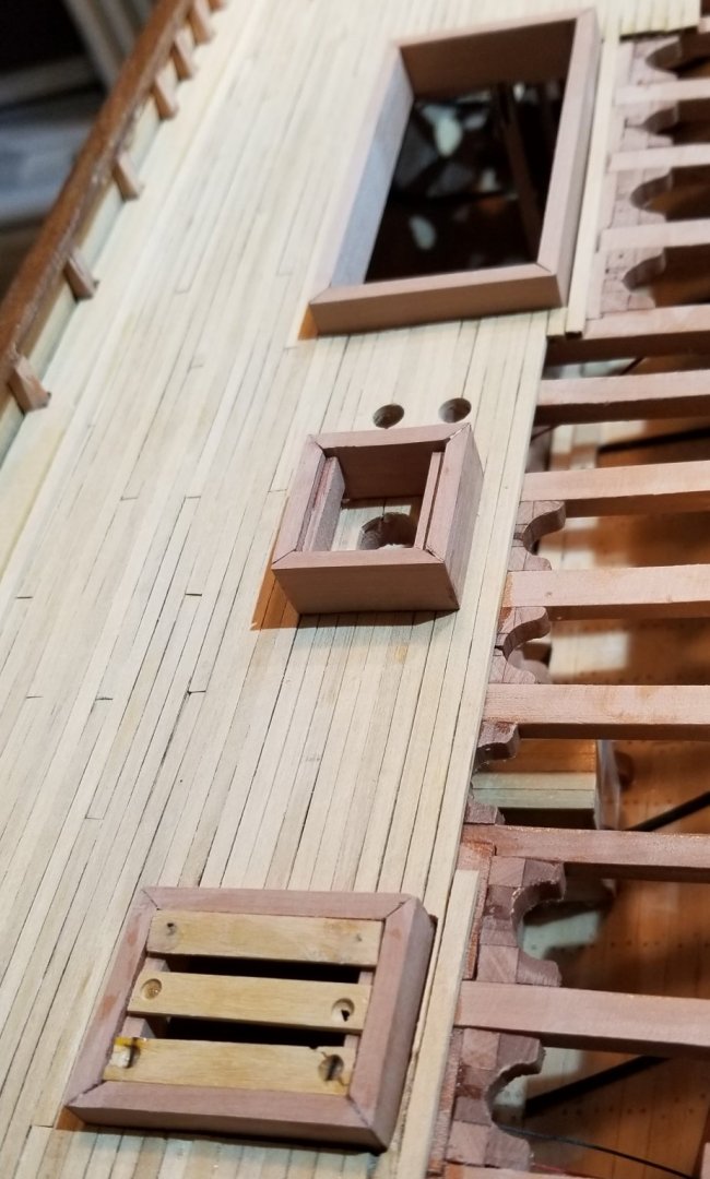
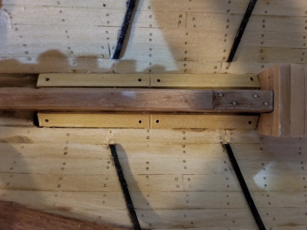
Before getting to the hatches, I just wanted to mention that I tried to make the pintle and gudgeons out of brass strips and failed completely. I've done very little metal work over the years and it shows! Bending the stuff cleanly was impossible for me. This probably means that I'll be doing all the rigging ironwork with paper strips unless someone can guide me to a way of learning how to do the metal work. Now on to the hatches. The photo shows the three stages of creating the hatches. The main hatch {temporarily installed) shows the completed coaming. The smallest hatch (the fore hatch) shows ledges installed to support the hatch boards (aka hatch covers). The aft hatch (installed) shows 3 of 4 hatch boards in place. Notice the single planks starboard of the main hatch and aft hatch so that the hatches are completely supported by deck planks. The original sheer plan shows the fore-aft position of each of the hatches, but it does not show the width. I could have used Underhill's proportions but instead I used his actual widths. As I said somewhere earlier, the sheer plan's placement of the hatches is 2' - 3' forward of Underhill's placements. Now we can take a look at the hatch boards in the aft hatch. We are using 3" thick boards roughly 12" wide which are first cut to length to fit the coaming snugly - shown in the top most board in the photo. Then a 6" hole is drilled at each end but not all the way through. I drilled these holes in a drill press with the hatch boards resting directly on the top of the metal jaws of the vise. I drilled gently until the bit just touched the metal. There was a small hole at the bottom that I filled with wood putty - shown in the middle board in the photo . Then a blackened brass wire was inserted into a hole drilled in the edge of the hatch board from one side to the other passing through the middle of the 6" hole - shown in the lower board. The wire simulates a 1/2" iron bar which is easily grabbed in the 6" hole. I'm not sure what I'm going to work on next.
- 108 replies
-
- 3
-

-
- leon
- brigantine
- (and 1 more)
-
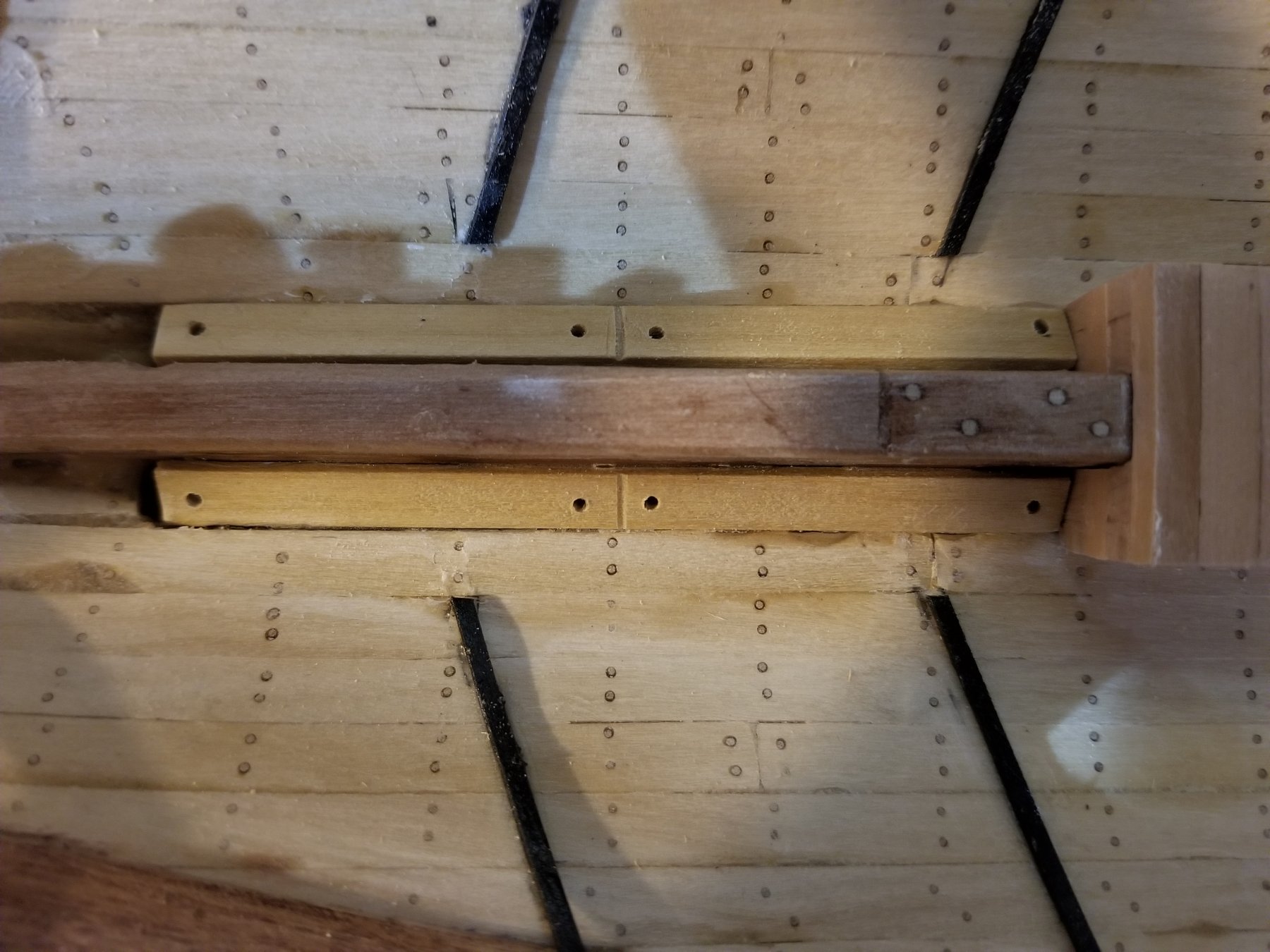
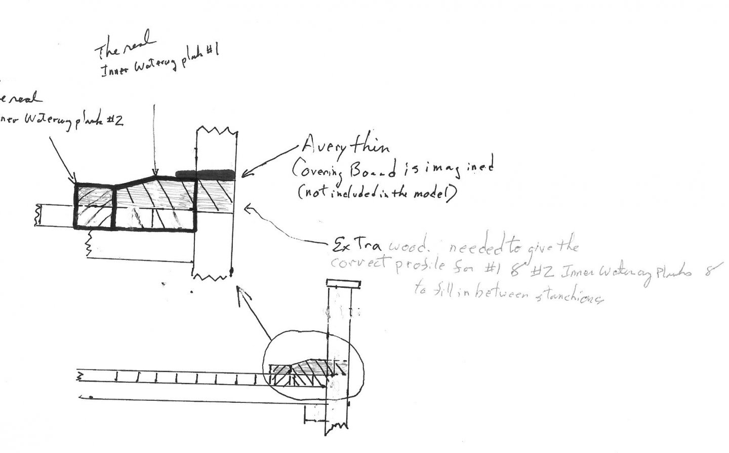
In this post, we show the waterway and an adjacent plank (called by the DNV survey Inner Waterway Plank #2). Some of the information in the survey is confusing - it mentions an Exterior Waterway Plank (I have no idea what this is) , the Covering Board is given as 6 3/4" wide (much narrower than a conventional covering board) and there is no mention of a margin plank. The Inner Waterway Plank #1 is 8" thick x 12" wide and thus can be taken as THE waterway. The Inner Waterway Plank #2 is 5" thick x 6" wide - no obvious name comes to mind for this. To my eye, the 12" wide waterway seems quite large so I made a quick comparison to two other ships - the full rigged ship, Young America, and the three masted schooner, CA Thayer. The ratio of the waterway width to the beam on the weather deck is 2.6% for YA and 2.7% for CAT. Leon's ratio is 3.6% - a third larger. This is probably another indication that Colin Archer built his ships strong since the waterway was a significant timber. It can be seen that I notched the waterway around the stanchions. This gives the impression of a covering board without actually including one. I did this because I couldn't make sense of the information on the covering board in the survey. Any comments on the way I handled this will be warmly welcome! Next, I'll be fitting the three hatches.
- 108 replies
-
- 5
-
-
- leon
- brigantine
- (and 1 more)
-
Wefalck, Thanks for the thoughts! The whole descriptor for top timbers was " Futtock by covering board (top timber)" [This is a location for giving the dimensions of the frame] which doesn't really answer your question but I think according to typical practice this suggests that the top timbers were the stanchions. passing up through the covering board. Your suggestion about the quarter round rabbet allowing the 2nd inner waterway plank to act as a margin plank is creative although the carpentry of intersection would be pretty complex I think because joggling would be necessary and cutting a receiving jog in the 'margin plank' could be very tricky. And then a valid question would be why introduce the complexity. Hey, I just had a thought - what if they just don't mention the margin plank that would be inboard of the 2nd inner waterway plank. The survey might not mention it because it is not a structural timber. Oh well! In any event I'm not willing to do the jogging! Your comment about "most of the planks are sitting on the deck-beams and certainly not on the deck-planking" is of course true. I should have mentioned that the only reason I'm putting the two inner waterway planks on the decking is for simplicity and ease of execution for example the notches for the stanchions are less deep and hence easier to cut and have snug. I tried to find the FRIIS-PEDERSEN books but was not successful either on the internet or amazon. Any help here? I'm including a drawing of what I think I'm going to do in the spirit of " play around with the cross-sections of the planks to see how the puzzle might fit together." The covering board is, I'm going to say, sort of being represented by the top surface of the inner waterway plank #1. The Outer waterway plank is being ignored because I haven't the foggiest idea of what it is. I'd love to hear your thoughts on whether what I'm planning (shown in the diagram) will have the right 'feel'. #184 posts Location New Jersey, USA Report post #1 Posted yesterday at 03:02 AM
-
Tailing deck beams
Doug McKenzie replied to allanyed's topic in Building, Framing, Planking and plating a ships hull and deck
Allan et. al. In reference to where dovetailing the deck beams ends into the clamp was used, Norway is another place. The 1880 DNV classification rules even make it sound as if dovetailing can be used instead of knees (seems pretty unlikely, but who knows!)- "All deck beams to be securely fastened to the sides of the vessel by knees, either hanging or lodging, OR [emphasis is mine] by being dovetailed or doweled into a shelf; the inner overlaying stringer and waterway being let into the beam." I'm not clear on what it all means, but it seemed interesting. Doug -
Folks, I have an 1880 DNV classification survey for brigantine Leon and I can't interpret some of it and would love help: Items identified in the survey: Covering board - 3 1/4" thick x 6 3/4" wide Outer waterway plank - 7 1/2" thick x 5" wide Inner waterway plank, 1st plank - 8" thick x 12" wide Inner waterway plank, 2nd plank - 5" thick x 6" wide Deck planks - 3" thick x 6" wide Top timbers - 9" sided x 6 3/4" moulded My thoughts and questions: What is an outer waterway plank? I imagine that the Inner waterway plank, 1st plank is a normal waterway. I imagine that the Inner waterway plank, 2nd plank is a binding strake. I don't think it can be a margin plank because I think those have to be the same thickness as the deck planking. The width of the covering board is the same dimension as the top timbers (moulded)- does this mean the 'covering board' is little segments meant to fill the spaces between the top timbers? How can a normal covering board be this narrow? No margin plank is mentioned - how do the deck planks terminate? In the absence of additional info, I am probably going to put in a waterway of 5" thick x 18 3/4" wide - 5" thick (not 8") because the waterway will be sitting on top of the deck planks rather than on the deck beams. 18 3/4" wide (not 12") because I'll notch out for the top timbers and let the waterway fill the gaps out to the inside of the bulwark planking. I'll also install a binding strake of 2" thick x 6" wide - 2" thick (not 5") because the waterway will be sitting on top of the deck planks rather than on the deck beams. This arrangement seems to me to be the easiest to execute and still give the right overall impression of what this area of the ship might have looked like. I would really appreciate any comments or suggestions on how to model this based on the survey information. Thanks, Doug
-
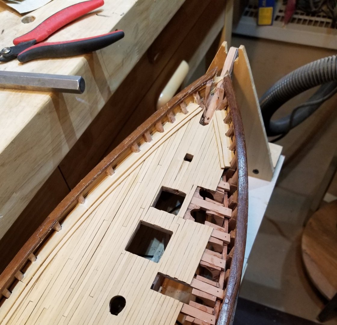
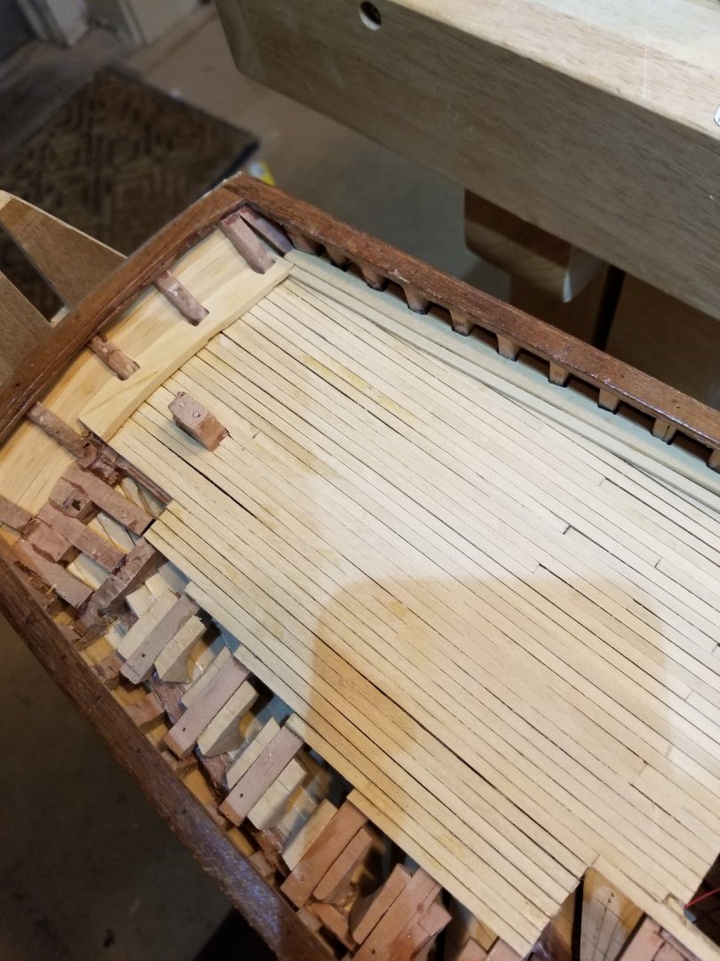
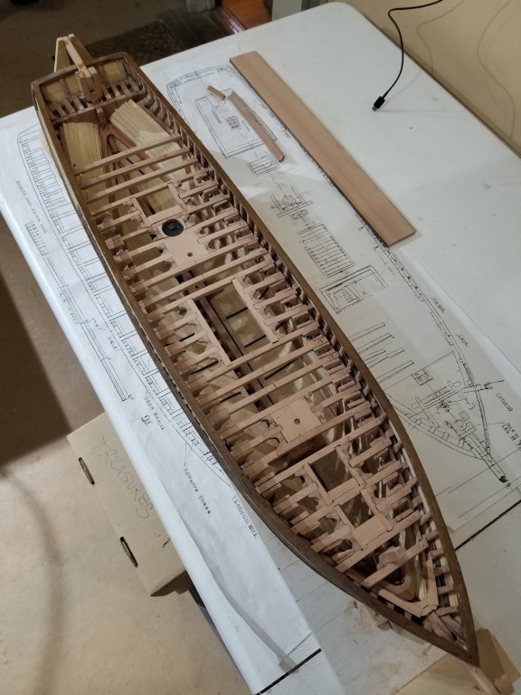
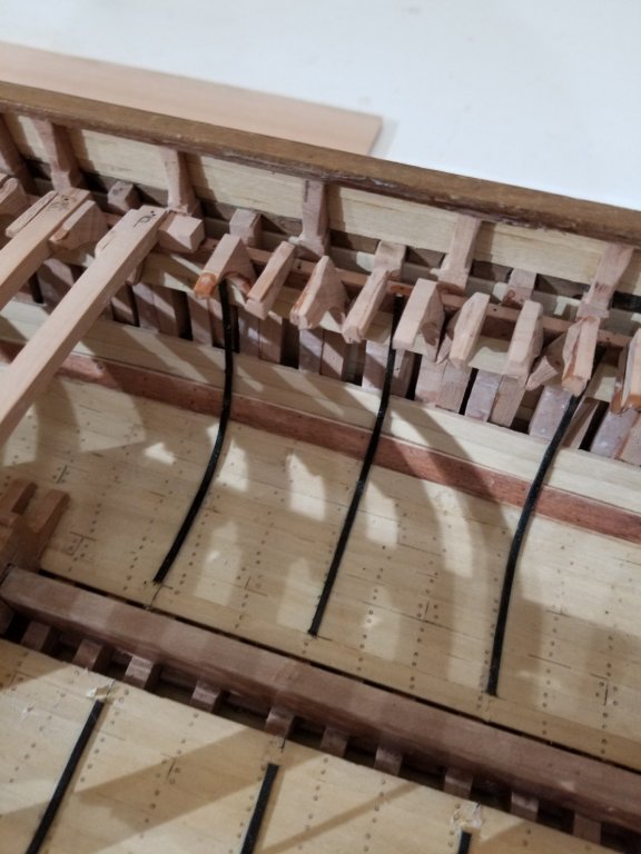
The deck planking is well underway. pencil lead on the edge of a plank simulates caulking. Only the port side is going to be completely planked. I'm going to plank around the various openings on the starboard side so that the deck items sit flush all around. This view at the bow shows how the deck planks are carried between the bulwark stanchions. This will provide some support for the waterway which will extend all the way out to the inner face of the bulwark planking. We are making significant simplifications from the survey in the margin plank, waterway and cover board timbers. This will be discussed more fully in the next posting. Till next, Doug

- 108 replies
-
- 6
-
-
- leon
- brigantine
- (and 1 more)
-
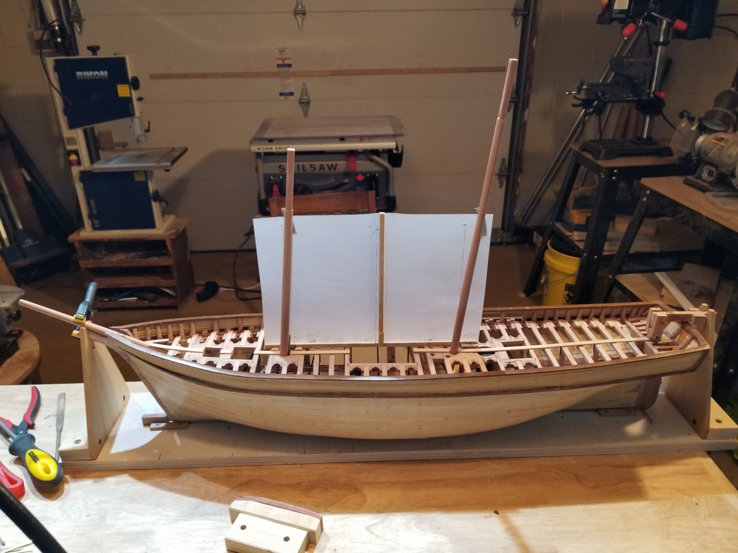
I wasn't planning to make a post at this point, but when the king plank was installed it looked so cool I had to record it. Now I may be able to stop telling my wife "Wow that king plank is cool" I've also put in the two lower masts and the bowsprit. The vellum screen is a jig to set the mast rakes correctly- here they were used to make sure the mast step mortise and the holes through the partners provided enough flexibility to permit the correct rake. Later, when the deck and deck items are done, it will help in the final fitting of the masts. The camera distorts the rake but they are a respectable 4.2o and 5.8o while Underhill's were 1.7o and 3.4o . The ones I used come from the Sheer Plan - they may not be right as sometimes contemporary plans are not exactly right but since they are reasonable, I decided to use them.

- 108 replies
-
- 10
-
-
- leon
- brigantine
- (and 1 more)
-
Thanks Sea Hoss. My wife thinks I must have sailed on Leon in a previous life. It's the only reason she can think of to explain why I enjoy working on her so much.
- 108 replies
-
- 1
-
-
- leon
- brigantine
- (and 1 more)
-
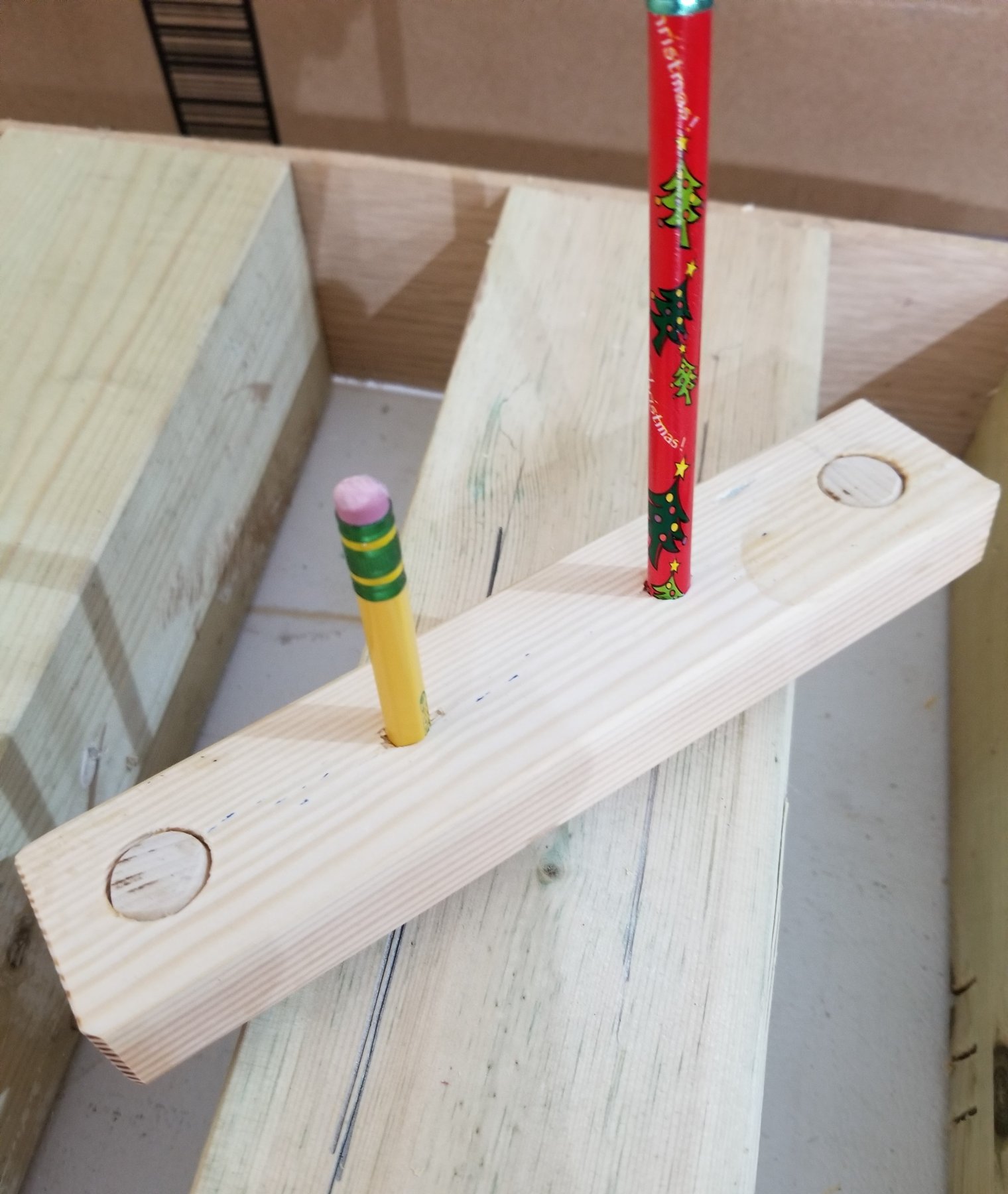
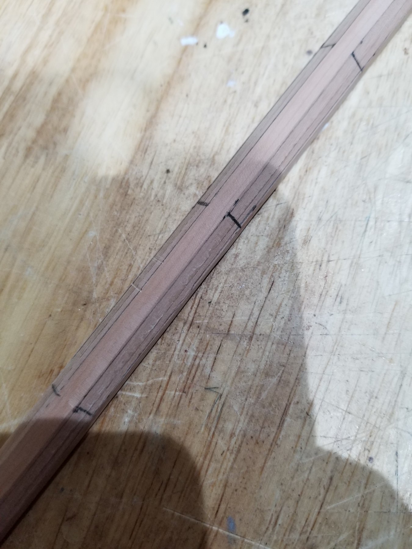
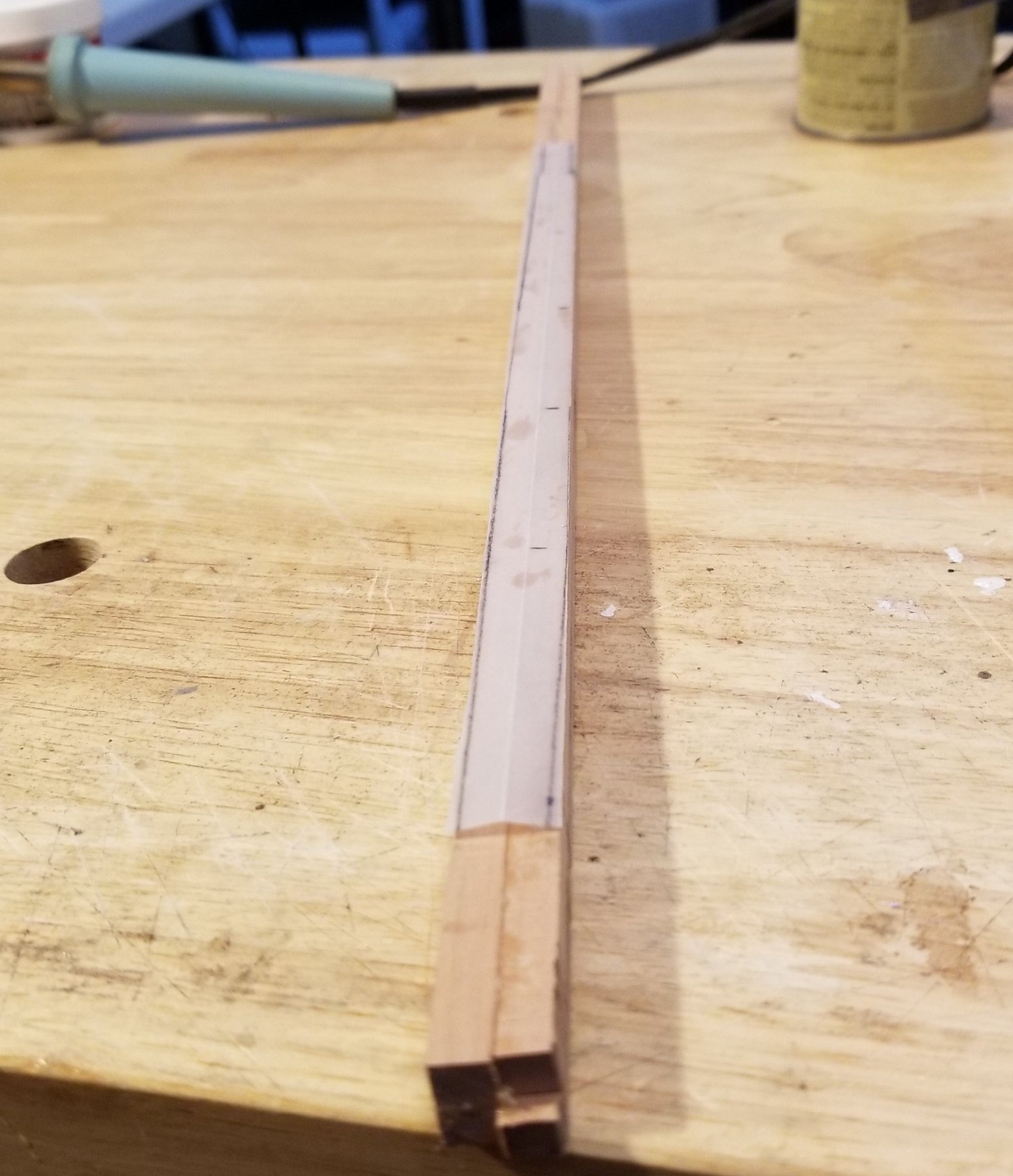
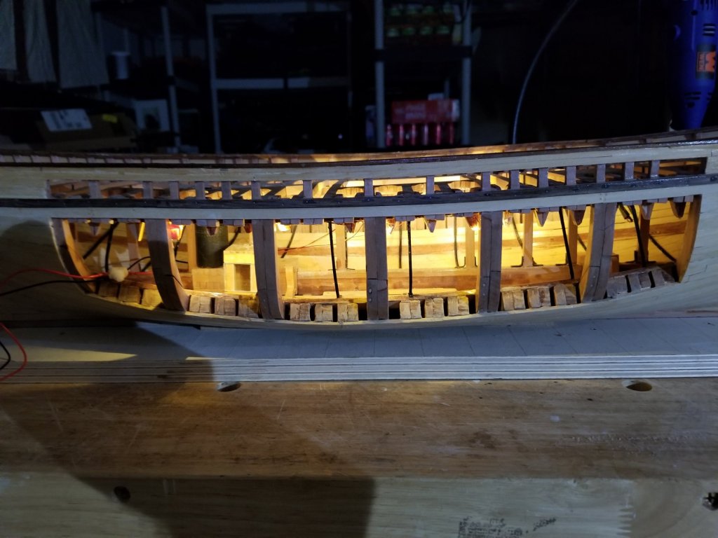
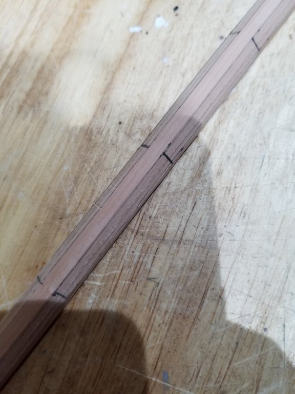
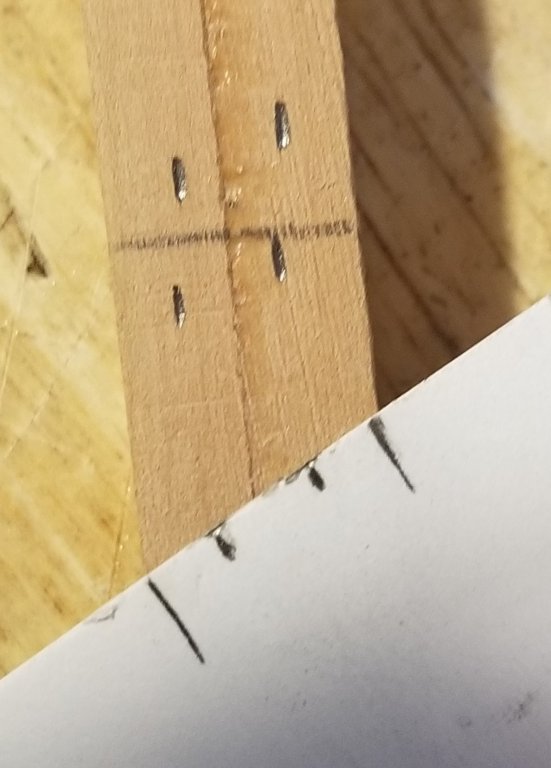
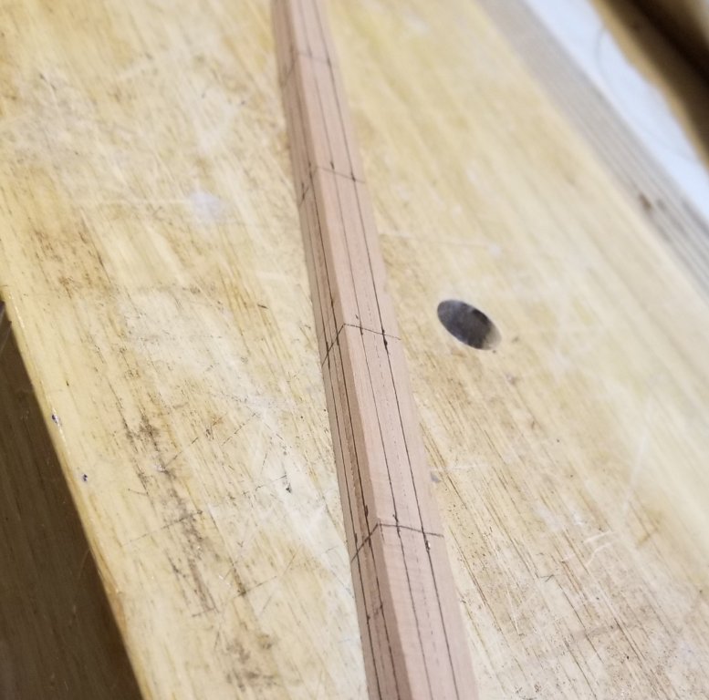
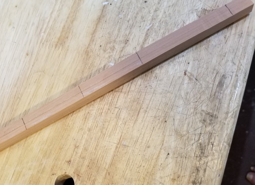
In the photos below, the viewing ports are shown without lights on and with lights on. 8 chip LEDs run from a 9v battery. I haven't figured out yet where to put the battery and the switch. Before fairing the deck beams and planking the port side of the deck, I decided to describe making the fore lower mast. The reason for this is that when I built Little Leon, a 16' LOD 'model' of Leon that sails with 2- 4 people, I used the actual ship yard technique on all 14 spars and had a lot of fun doing it. This technique requires a sort of jig and I couldn't remember its name so I did searches in NRG-MSW and the internet to find out what it's called. I was very surprised to find very few references to this technique. As a result, I figured I could describe it in case anyone was interested. I have always built the spars up from 4 square sticks glued together to ensure that the spars stay straight. The four sides are cleaned up leaving a square cross section. The 3 quarters are marked along with the heel, partners, hounds and head. Tables show the diameter of the mast at each of these points as a percentage of the diameters at the partners. On big spars, e.g 2", I mark those diameters directly on the wood but on the 1/2" lower fore mast of the 1:48 model, I used paper. In either case, smooth curves are drawn. I used a band saw to remove the extra wood and then sandpaper cleans things up. Now the same curves need to be laid out on one of the cut surfaces. If the curves were drawn on both sides at the start, one set is destroyed when the first tapering is done. Cleaning up the four tapered sides with sandpaper allows you to make sure all the cross sections are square. Now we need to mark the lines that guide us when beveling the corners of the square to form an octagon. This is the first step in making the mast round (except for the hounds to head which stays square and the housing, heel to partners, which will stay octagonal). Ideally, you can make a jig, whose name I don't remember, as shown below. By keeping the guide pins pressed against the square spar the pencils will mark the required curves. With the jig, these curves are drawn quickly and accurately. The photo below show a 5" jig drawing the curves on a 4x4, On the 1/2" lower fore mast, I couldn't see how to make a jig so I just marked a piece of card and used it like the jig. It takes a lot longer but at least it gets the job done. The card is reversed to make another pair of marks because this compensated for slight errors in the marks on the card. After the octagonal curves are drawn on all four sides, a plane can be used to remove most of the bevel but you won't want to go all the way to the lines. The reason for this is that its important to make sure that the 8 surfaces are all the same width - that's more important than meeting the lines which might be slightly in error. Fortunately there is an easy method for making sure the 8 sides are all the same size. It requires that before the planing starts, lines are drawn on all four faces at the stations between the heel and the hounds. The octagonal curves and the station lines are shown in the photo below. The next photo shows the mast after the 4 bevels have been removed. At each station, we compare by eye the width of the bevel (no station mark) with the width of the station mark that is visible. These widths should be equal. The picture distorts these widths - actually they are equal. When the octagon is finished, the mast is rounded between the partners and the hounds. In the shipyard, the octagon is taken to a 16 sided cross section and then to 32 sides and then to a circle.


- 108 replies
-
- 12
-
-
- leon
- brigantine
- (and 1 more)
-
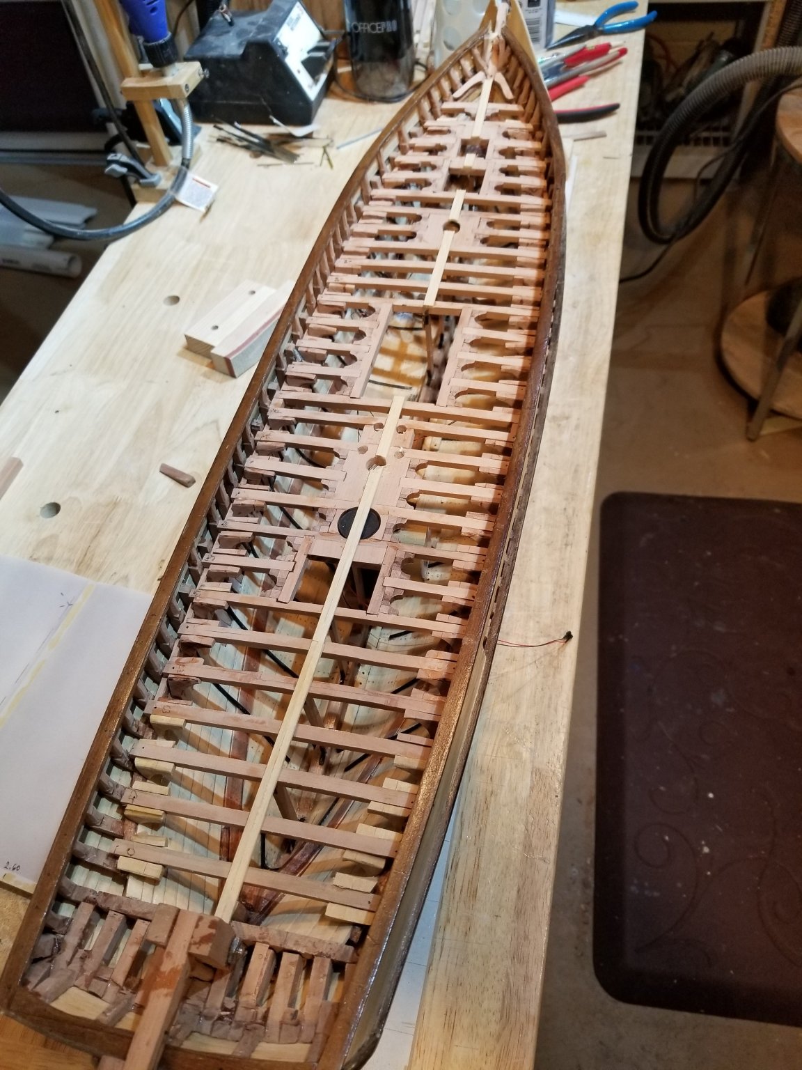
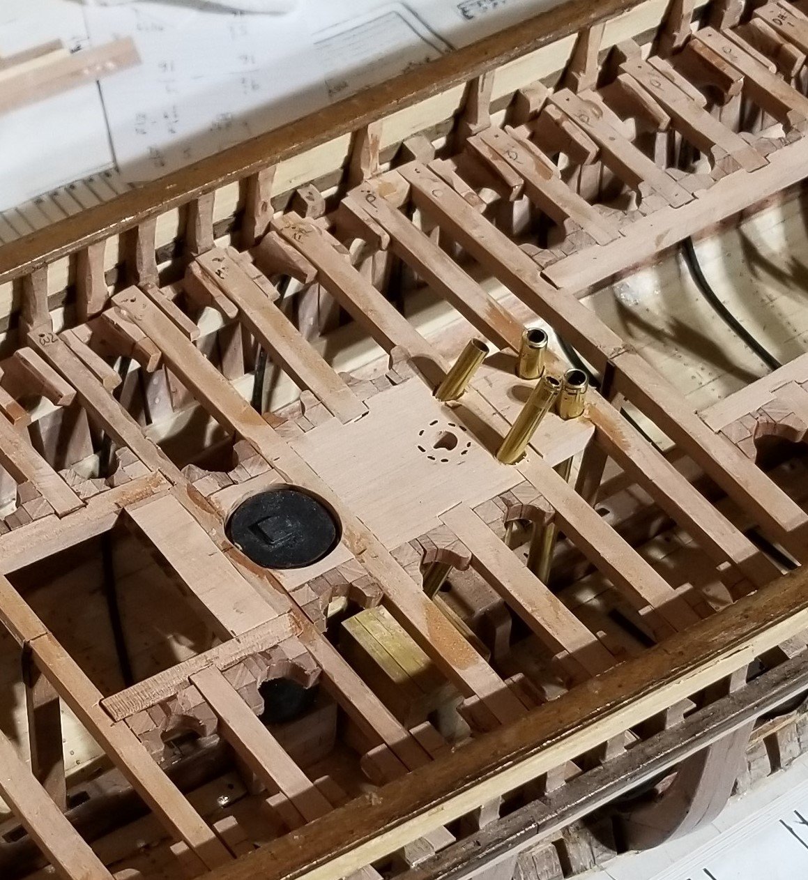
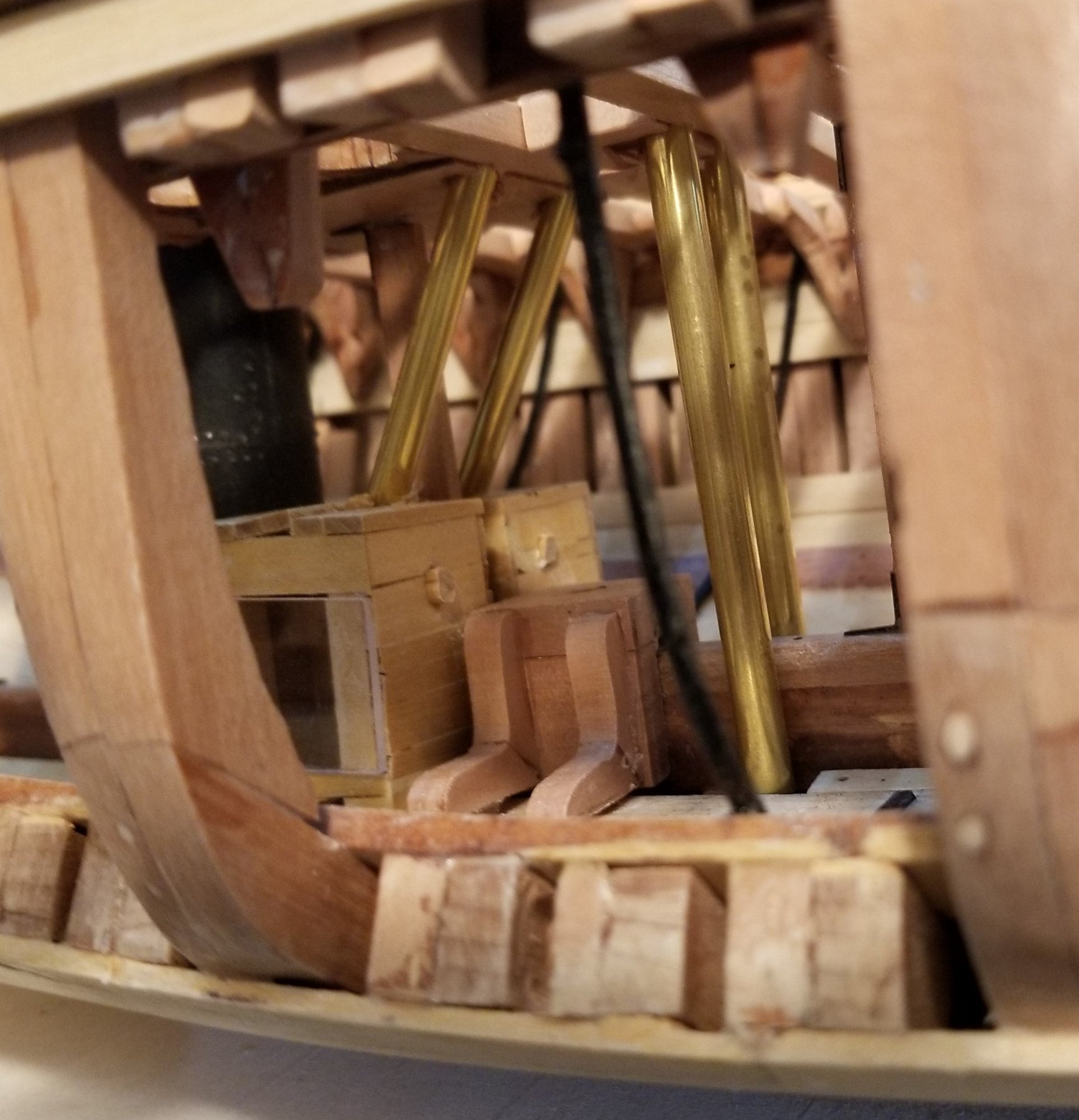
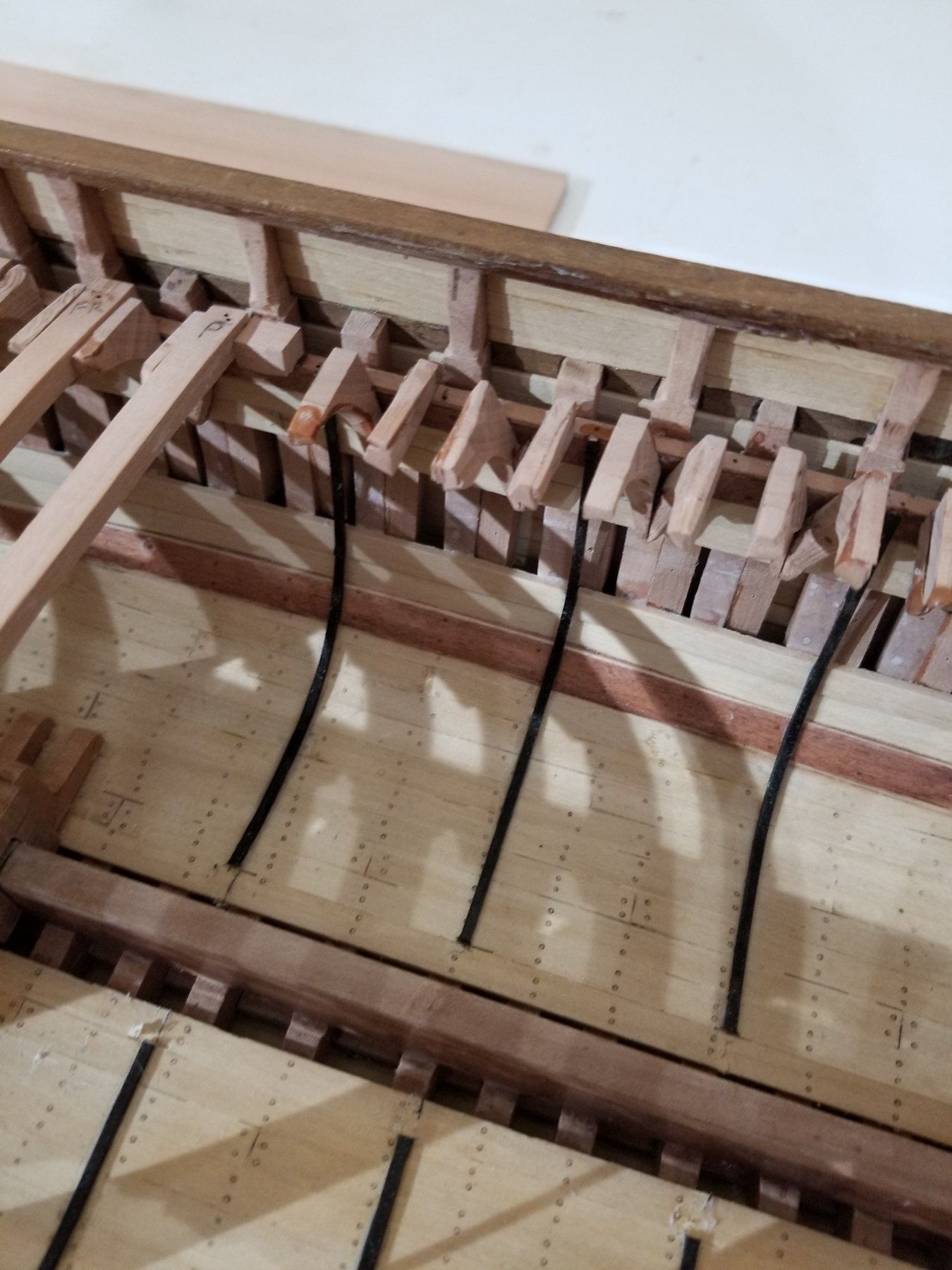
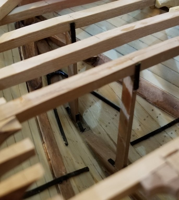
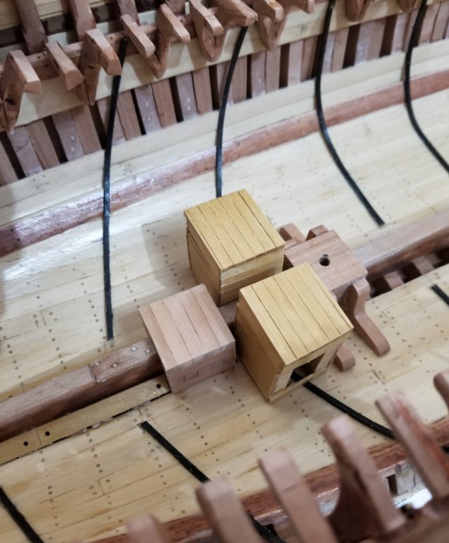
All the stanchions are in place and the deck beams have been glued to the deck clamp and the diagonal hanging knees. The anchor chain pipes slope aft to the anchor chain lockers. The bilge pump pipes drop nearly vertically to the bilges. These pipes will all be blackened before installation. From the hold, the anchor chain pipes are seen to enter the lockers on their tops. On the front surface of the lockers and a little above the main mast step, can be seen bungs that represent the fastening of the bitter end of the anchor chain to the locker. The purpose of this connection is to prevent the chain from running free hence losing the chain altogether. There are emergency situations, however, when we do want to lose the chain. In these situations a mallet is used to break the connection. Although there is very little documentation on this equipment there is one rather humorous comment. We paraphrase this comment as - "You want to be able to break the connection from outside the locker since, in an emergency, it would be inconvenient to have to enter the locker." The bilge pump pipes just drop into the bilges. Both sets of pipes will be blackened. In the picture below, the stanchions can be relatively clearly seen along with how the tops of the stanchions are attached to the deck beams. How wonderful it would be if Stephen Maggipinto of the Ship Model Society of New Jersey could take these pictures - they would be clear, sharp, well lit, etc, etc, etc... I will refrain from characterizing my pictures made with my phone. . Work that follows: 1-- Add little lights because the hold is pretty dark with the deck beams in place. 2-- Fairing the deck beam tops to receive the deck planks. 3-- Plank the starboard side of the deck leaving the port side open.


- 108 replies
-
- 8
-
-
- leon
- brigantine
- (and 1 more)
-
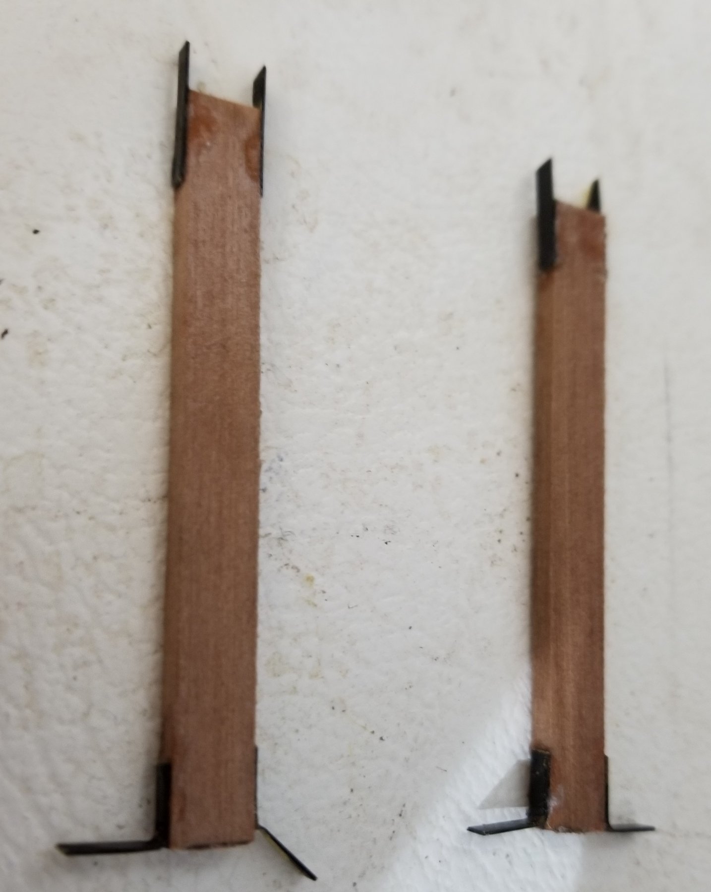
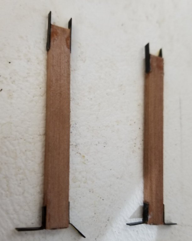
We start the installation of hold stanchions and the simultaneous gluing the deck beams into place from the stern as there are no more internal details back there. The stanchions are 4" x 10" and the deck beams are sided 11 1/2" (both from the survey). The picture below shows how the top of the stanchions are prepared to be attached to the deck beams with two straight 24" iron plates (from the CA Thayer). These plates are modeled as if the 10" width of the stanchion is the same as the 11 1/2" side of the beam. The bottoms of the stanchions will be fastened to the top of the keelson with 2 iron "L"s with each leg being 12". A detail - Should the 4 vertical corners of the stanchions be beveled? CA Thayer's were not, so I left the corners sharp. The tops of the stanchions are not glued qt this time. That will wait until a number of beams are glued in place and then an accurate centerline can be drawn and the stanchions can be positioned accurately. Another detail - Since the stanchions support every other deck beam, should there be a stringer across the tops of the stanchions to support the unsupported beams? CA Thayer does not appear to have such a stringer. Even more important the survey does not mention a stringer and I would think that it would if it was there because it would be very visible and it is clearly structural..
- 108 replies
-
- 6
-
-
- leon
- brigantine
- (and 1 more)
-
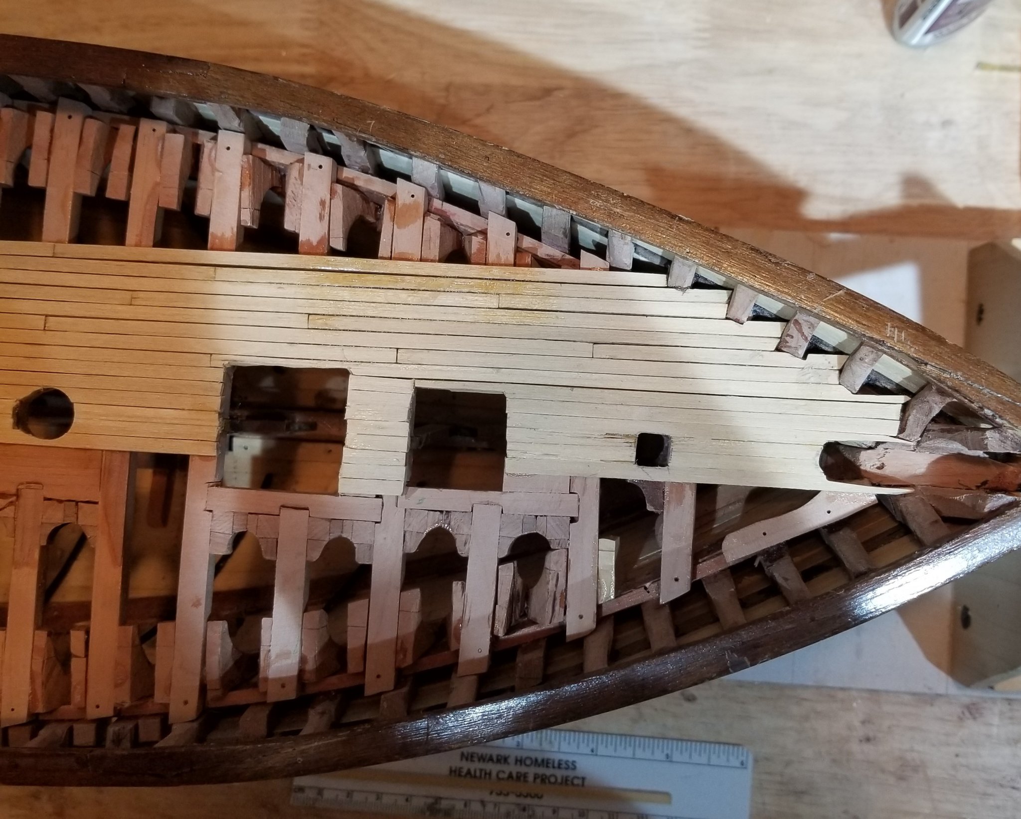
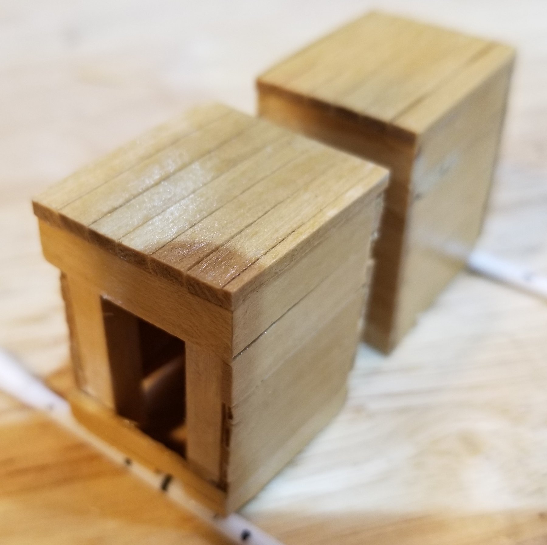
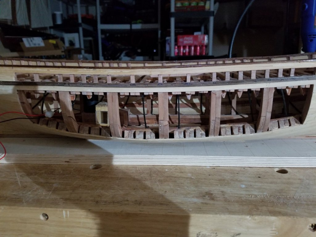
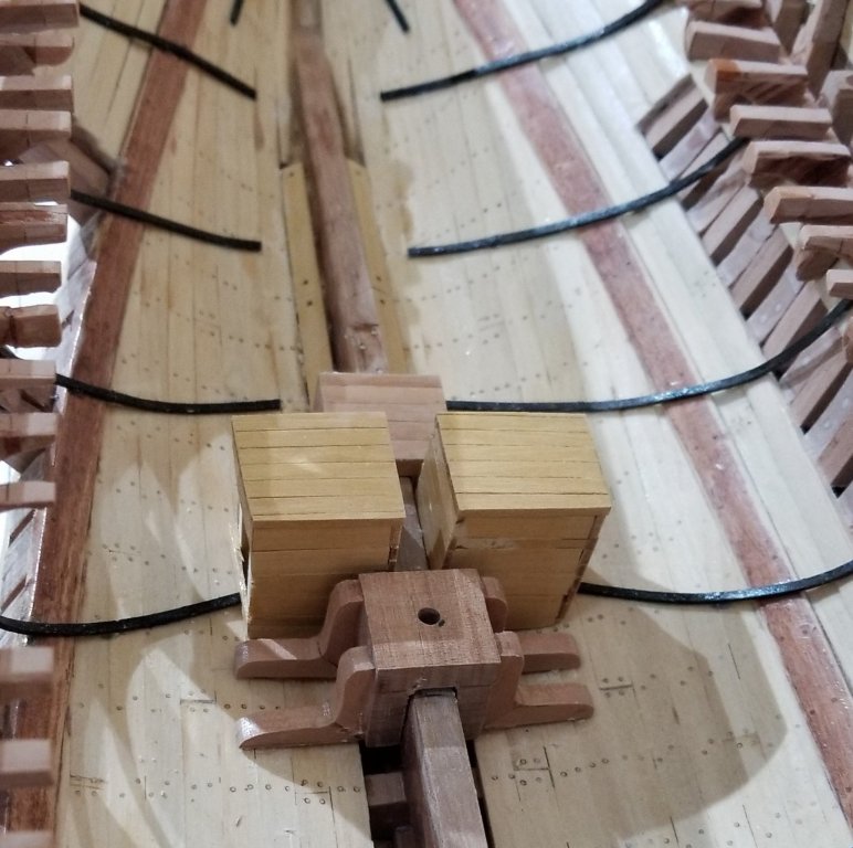
The structure of the hull is complete now - everything that remains is internal details, i.e. limber boards, anchor chain lockers, bilge pump pipes and hold stanchions. Our primary sources do not discuss any of these internal details (except hold stanchions!). As a result, we typically use Underhill to identify the location of these details (from his deck plan) and other sources to suggest plausible appearance. The limber boards are shown as roughly 8' lengths with 3" hand holds. Two adjacent boards are from one piece of wood with a notch to suggest the butt joint. This is done so that we can install a longer piece of wood and make a neater job of it. Here, the aft most boards are shown butting up against the base of the fresh water tank. I chose not to bevel the top edge of these boards because there was no consistency in the 'other sources' on this detail and having less sharp edges makes some sense. The two chain lockers are located on either side of the main mast. This is a puzzling feature of Underhill's plans. The tops of the anchor chain pipes are located virtually on either side of the main mast or about 64% of the LOD from the bow. The vast majority of ships in the 2nd half of the 19th century that I am familiar with have their chain lockers well in the bows generally below the windlass so that the chain drops off the windlass directly into the chain pipes. A few ships have the chain lying on the deck from the windlass back to the chain pipes but only for a short distance. The question is, why did Underhill show the chain on the deck for about 52% of the LOD aft of the windlass. The first objection could be that it seems to be an extremely rare layout. The second objection could be that carrying deck cargo does not seem consistent with so much chain lying around on the deck - this objection was brought to my attention by Wayne (trippsw). We have a newspaper article, however, that refers to Leon having lost all her deck cargo so we know she carried stuff on her deck. The dimensions that were picked for these lockers was 4' by 4' by 6' high. (The square section is advised for strength.) The dimensions give a volume of 96 cu ft which is about 35% more than a table of chain volumes (in Desmond, Wooden Ship Building) indicates. One side is left un-planked and will receive a little piece of plexiglass so that the chain can be seen through the 6 ports. In the following photo the chain lockers can be seen nestled between the main mast step and the fresh water tank base. In this forward looking photo below, a small piece of one of the knee riders can be seen through the un-planked side. This is a reminder that these anchor lockers had no bottom. The chain merely piled up on the ceiling. Other lockers hung from a deck and those, of course, had bottoms. Notice the tops of the two diagonal knee riders. They are sloped at the same angle as the diagonal hanging knees - 20 degrees. This compares to the 20 - 35 degrees that the Rules and Regulations require for riders in ships greater than 900 tons. Holes will need to be drilled in the tops of the lockers for the tubing which will represent the chain pipes

- 108 replies
-
- 8
-
-
- leon
- brigantine
- (and 1 more)
-
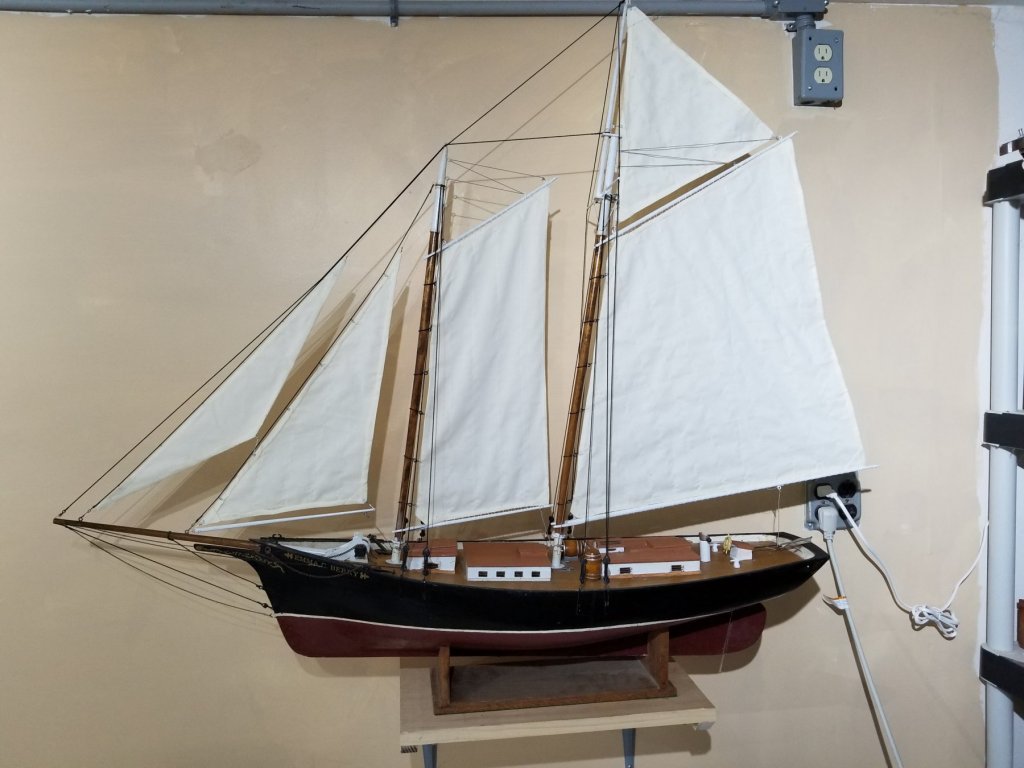
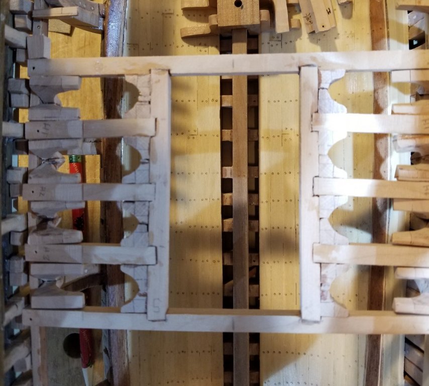
Well, it's been about 3 or 4 months since I've posted anything on Leon. This is because I've been refurbishing a model that I built about 35 years ago of the schooner Emma C Berry. A trip down the Danube and some sickness took up the rest of the time. So here's the Emma on her shelf in the garage awaiting her first sail. Leon's deck framing is nearing completion as there are only 3 or 4 frames left in the stern. So now the internal detail needs addressing since we can't glue the deck structure down until all the internals are taken care of. The first internal detail is the iron knee riders. From the survey we know that these were installed at every other beam. They were about 11/2" thick and 3 1/2" wide. From the rules and regulations we know that these riders could be installed either perpendicular to the keelson or diagonally. Because of the use of diagonal hanging knees, it makes sense to use diagonal riders. The R & R also says that around the main hatch the riders are perpendicular to the keelson and that is what is shown in the picture below. The R & R also says that in the case of a ship like Leon, these knee riders only go to the top of the deck clamp/shelf and they are not fastened to the deck beams. They proceed down far enough that 1 or 2 bolts can be put into the floors.
- 108 replies
-
- 8
-
-
- leon
- brigantine
- (and 1 more)
-
Brigantine Leon by Beckmann - 1/48
Doug McKenzie replied to Beckmann's topic in - Build logs for subjects built 1851 - 1900
Hi Tomholly, Yes, I'm the original builder of Little Leon. John apparently has introduced a heavy discount because the last time I looked he was asking $110,000! My friends know that I sold it to John for $1,000 (yes you heard that right) and their main concern is that he pay capital gains on the difference. His pricing, btw, is based on an insurance valuation of $150,000 replacement cost. I had a most fun conversation with the underwriter coming up with that figure. You may wonder why I sold it for so little (material costs were $20,000). The reason is that Little Leon had passed into maintenance mode and she became a white elephant for me. I built her with found money and satisfied a lifetime dream by actually sailing a square rigger - at that point my project was complete. John and his wife were the first people who showed any interest in owning Little Leon and I offered her up for a price they couldn't resist - I remember that his wife told John that I had put the decimal point in the wrong place!. I believe that they had a bunch of fun with her on a lake in Kansas! It came as no surprise to me when they choose to sell her although I did tell my friends that they would never get more than $10,000 for her. Thanks for your post as this is the first time that I've told the story outside of my circle of friends. Personally, I think it's a pretty cool story as I was fortunate enough to be able to actualize such a wild dream that first arose when I was 12 years old. BTW I only came upon your post accidently which is why I'm abit late in responding. Doug Sorry, I never answered your question - no, there are no plans for Little Leon. I made plans as I needed them and then tossed them because I was not planning on building two. Actually I didn't so much toss them as I used them in the construction and they got cut up, glued to wood and ended up as trash. Now I'm building a pretty good model of Leon at a scale of 1 to 48. - the work is described in a scratch forum. -
Brigantine Leon by Beckmann - 1/48
Doug McKenzie replied to Beckmann's topic in - Build logs for subjects built 1851 - 1900
Matthius, I just realized that my primary contact in Norway, Jeppe,, might know something about the bell. I sent him an email asking if he knew where the bell was hung and he respond as below: "I don’t know, but I would think it was in the bow somewhere; forward on the mast, on the samsonpost or anchor windlass." Jeppe is assembling material on Colin Archer (the designer and builder of Leon) and his focus is primarily on Archer's now famous small boats. I think Archer only built 4 bigger boats one of which was Leon. Hope his comment helps. I'm also hoping that Jeppe will join NRG so that others will be able to benefit from his studies. Doug -
Brigantine Leon by Beckmann - 1/48
Doug McKenzie replied to Beckmann's topic in - Build logs for subjects built 1851 - 1900
Thanks again Matthius. One of the photos of HF 294 shows her outboard winch drum being even closer to the bulwark than in the first picture. Wonderful collection of photos. Doug -
Brigantine Leon by Beckmann - 1/48
Doug McKenzie replied to Beckmann's topic in - Build logs for subjects built 1851 - 1900
Beckmann, Great picture of the windlass. Do you know the ship? A feature of the photo is a comfort to me which is the relatively narrow space between the bulwark and the outboard drum - it appears to just allow someone to walk through the space I was forced to this same configuration on Leon because the fo'c'sle was shorter than Underhill had it hence the windlass is more forward and the bulwarks have come closer together. I calculated a width of the windlass for Leon by looking at about 9 other vessels and plotting the length of their windlass against the length of the vessel. It was pretty close to a line so I just picked off the length of the windlass for Leon based on her length. But I was uncomfortable with how close the outboard drum came to the bulwark. Because of your photo, however, I am no longer uncomfortable THANKS! Doug -
Brigantine Leon by Beckmann - 1/48
Doug McKenzie replied to Beckmann's topic in - Build logs for subjects built 1851 - 1900
Matthias, Boy, is she looking good! I like the various colors you used on the house tops and hatches. Johmo, Your comment about the forecastle capstan interested me as I had never felt that there was a problem with Underhill's placement. So I went back to the 1880 sheer plan of Leon that Jeppe found in Norway. There is a detail shown which suggests that the capstan was mounted about 2' 7.5" forward of the pawl bitt (which I believe is the same thing as a samson post). Underhill has the center of the capstan at 3' 6" forward of the pawl bitt. A lot of the difference is probably because Underhill's forecastle is longer (12' 0") than what we can estimate from the sheer plan (9' 6"). If we scale the 2' 7.5" up based on the ratio of the two forecastle lengths, we get 3' 4" which is pretty close to 3' 6" Perhaps I should explain that Underhill agrees quite closely with the original documents on many things. We attribute this to first, the fact that by 1880 deck layouts had become quite similar (within the variety of types that existed) and second, the fact that Underhill had the well known photo of Leon. Going further, this detail on the sheer plan shows (what we assume to be) a cylinder about 9" in diameter which extends between the weather deck and presumably the stem deadwood - it does not extend up to the forecastle which is why I say the sheer plan only 'suggests;' a capstan. The sheer plan has many imperfections so I don't think that this lack is a deal breaker. To further check if this interpretation is reasonable, we can compare this 9" cylinder to the Young America's (Tosti's) forecastle capstan support which extends down at least one deck (I couldn't tell how many). This capstan support has a diameter of 17". If we scale it down to Leon's size with length we get 7.5" and if we scale it down with breadth we get 11". These numbers compared to 9", I think, lend a little more support to the idea that this detail is describing the forecastle capstan support. I haven't finished the weather deck yet so I'll be tackling the capstan laten! Doug PS I'm documenting my Leon in the scratch build section. -
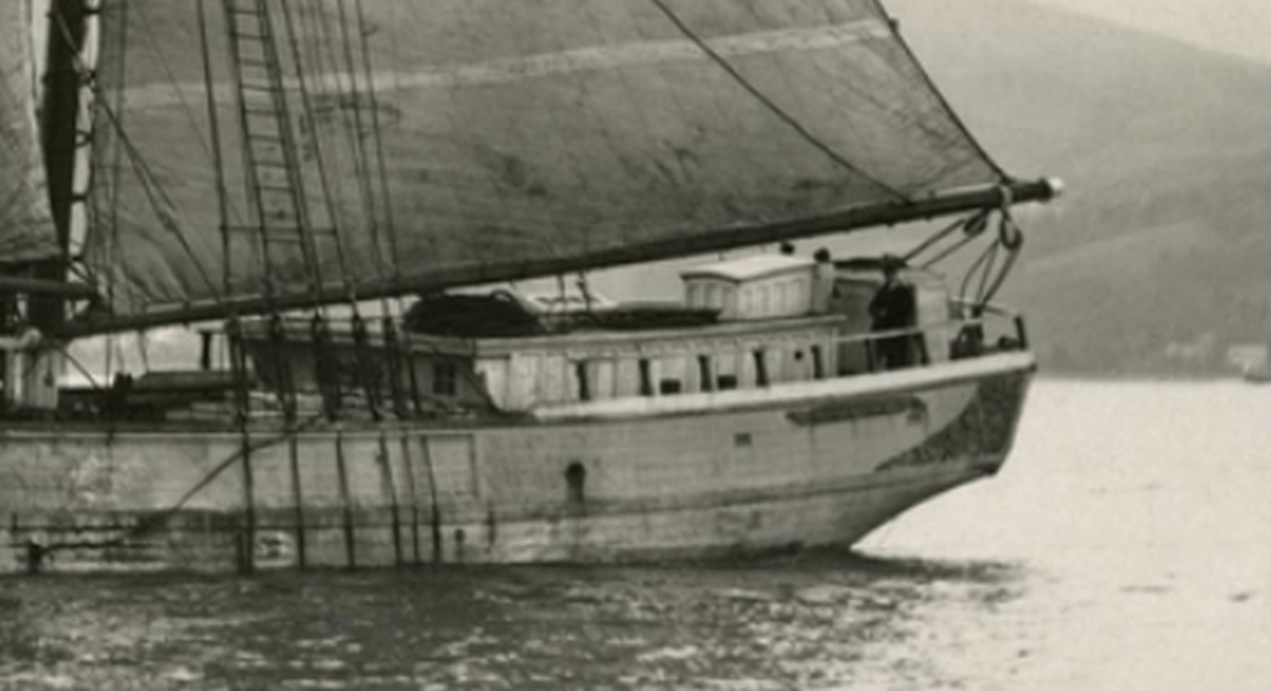
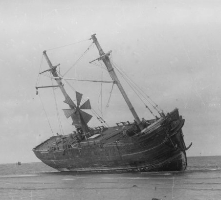
Kurt, Here's a view of the stern of Leon taken from the same photo. My guess is that Jeppe created this cropped version to send to me with good resolution but not too big for his email. It certainly indicates that the original photo had excellent resolution. We now have a little more info on when this photo was taken since the brigantine rig was cut down to a schooner rig in 1897. So she was at most 17 years old when the photo was taken. She foundered in 1915 when she was 35 years old so she was a brigantine for just about one half of her life. Doug

- 108 replies
-
- 3
-
-
- leon
- brigantine
- (and 1 more)
-
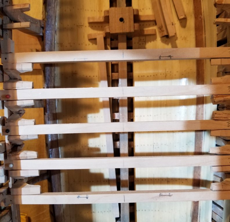
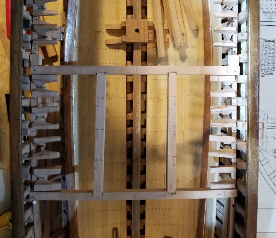
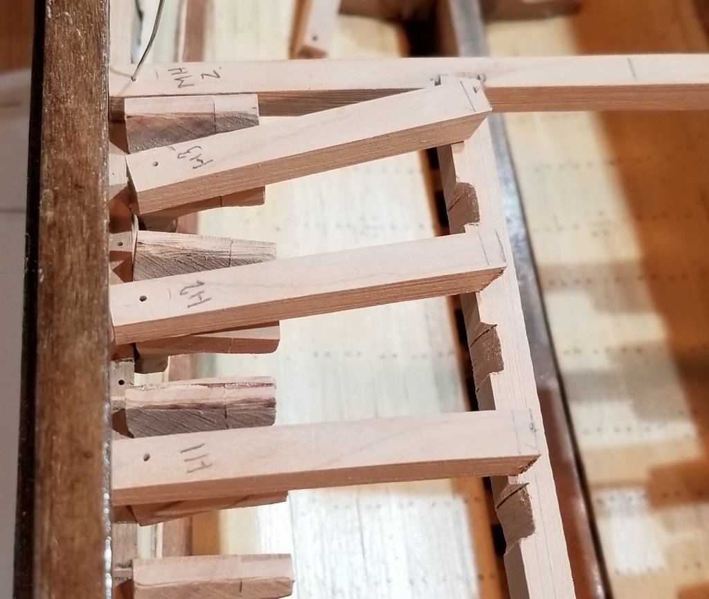
The 5 deck beams that span the main hatch are shown below. The marks for the 'scores' of the 2 carlings can be seen on the 2 outermost beams. The 2 carlings are in place and they in their turn are marked for the scores of the 6 half deck beams that will butt up against them. The scores are made in a simplified way shown below. With the 6 half beams in place the lodging knees are fitted. These were made in the same way as the diagonal hanging knees by glueing 3 sticks of 3/16" x 3/16" together in a cross section of an 'L'. Then, after some shaping, 3/16" slices become the raw knees. This whole assembly of full deck beams, carlings, half deck beams and lodging knees can be removed from the hull so that continued work on the interior is easy.
- 108 replies
-
- 5
-
-
- leon
- brigantine
- (and 1 more)
-
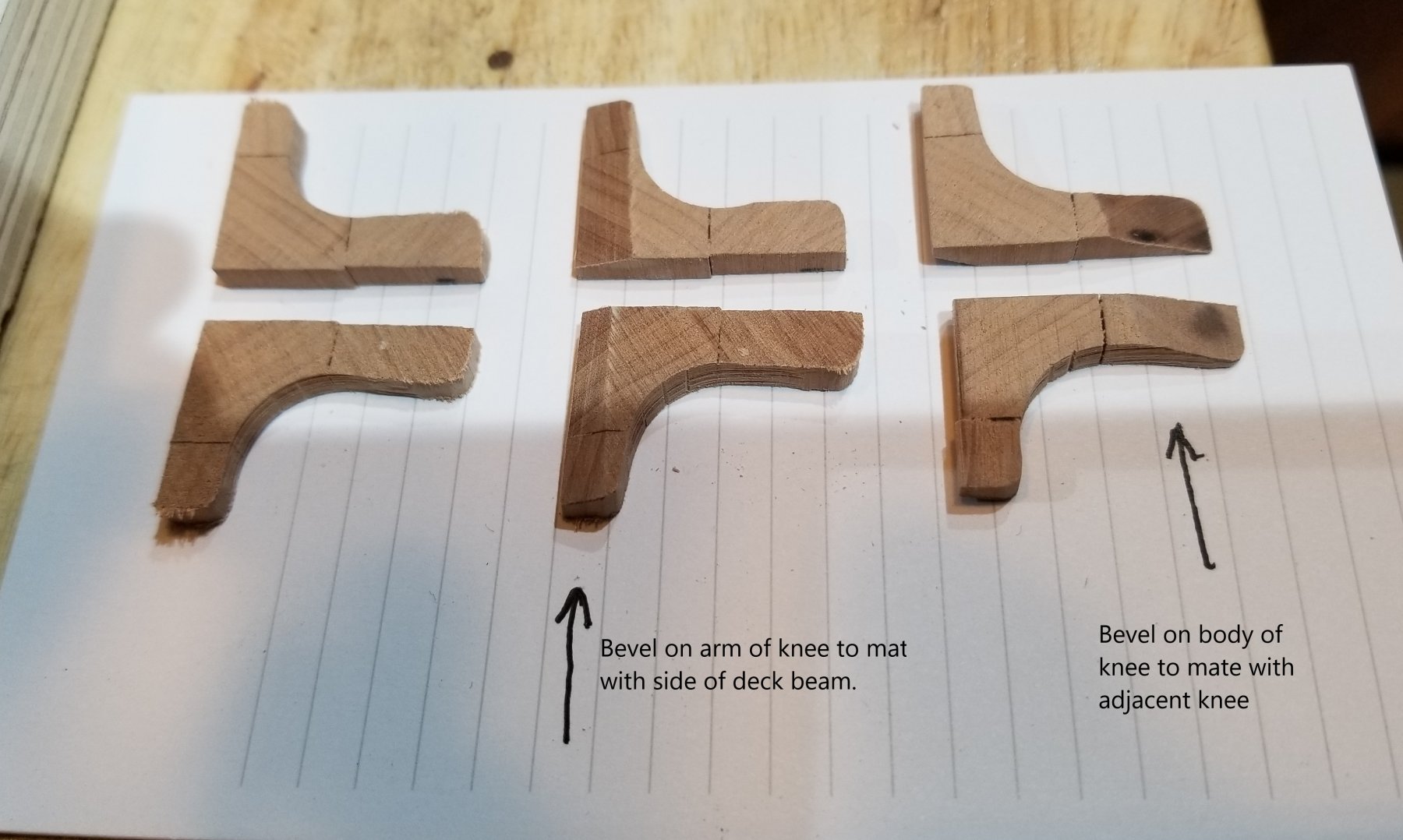
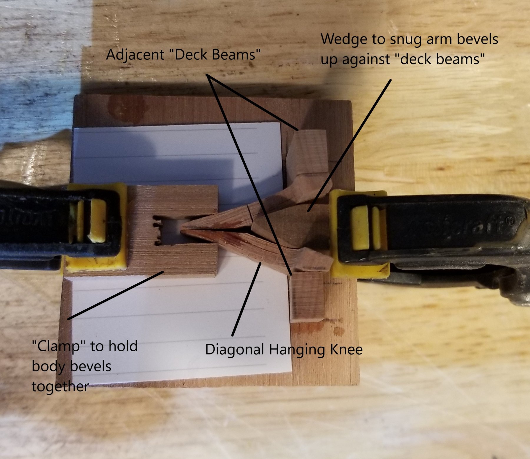
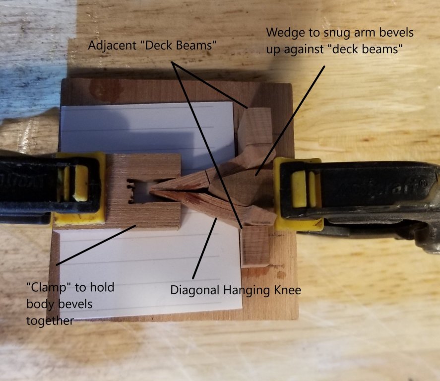
These diagonal hanging knees are apparently very rare so how they were made for the model is probably of little interest. On the other hand, posterity and all that... We start with the cylindrical shape of the knee (like a piece of molding) and then make slices to give the left hand pair (in the photo). The arms are then beveled so that the knee will fit flush against the side of the beam (center pair). The ends of the body are beveled so that the two knees mate. The jig used to glue the two knees together has two "deck beams" sticking up from the base. A wedge ensures that the arm bevels are pressed against the sides of the beam hence maintaining the correct beam spacing. The body bevels, which are glued together, are held together by a clamp. Note that the resulting 'compound' knee supports 2 adjacent deck beams. The two knees that support a single deck beam do not come into contact with each other and as a result cannot be 'compounded' and the compounding makes the fitting easier Finishing the knees involves fairing the tops of the arms to the top of the beams, rounding appropriate edges and fitting the knees to the clamp/shelf and ceiling planking. Doug

- 108 replies
-
- 3
-
-
- leon
- brigantine
- (and 1 more)
-
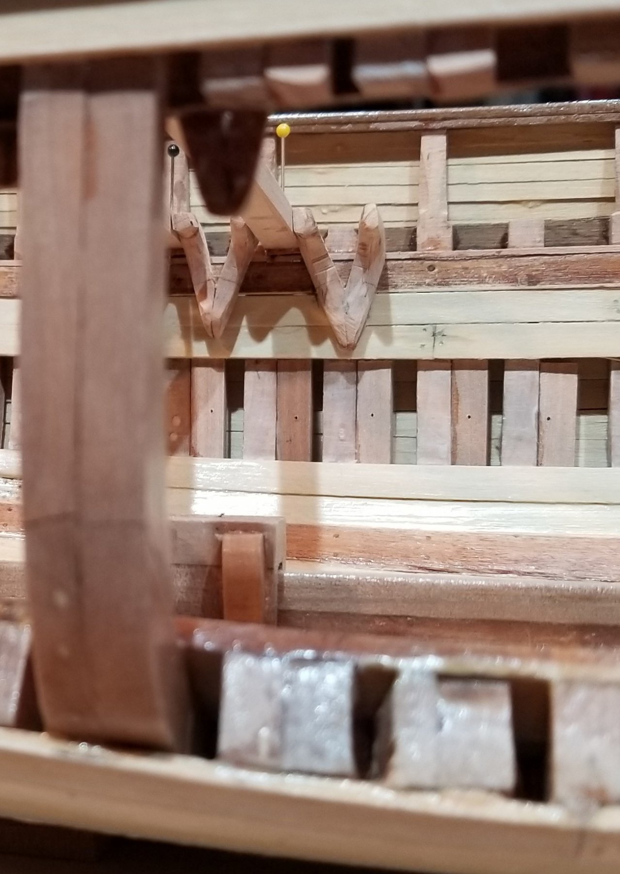
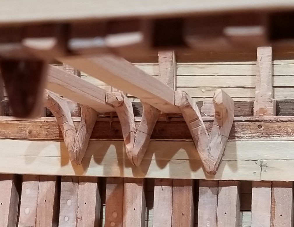
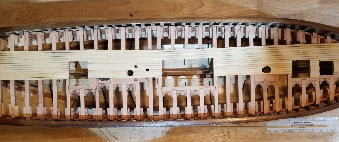
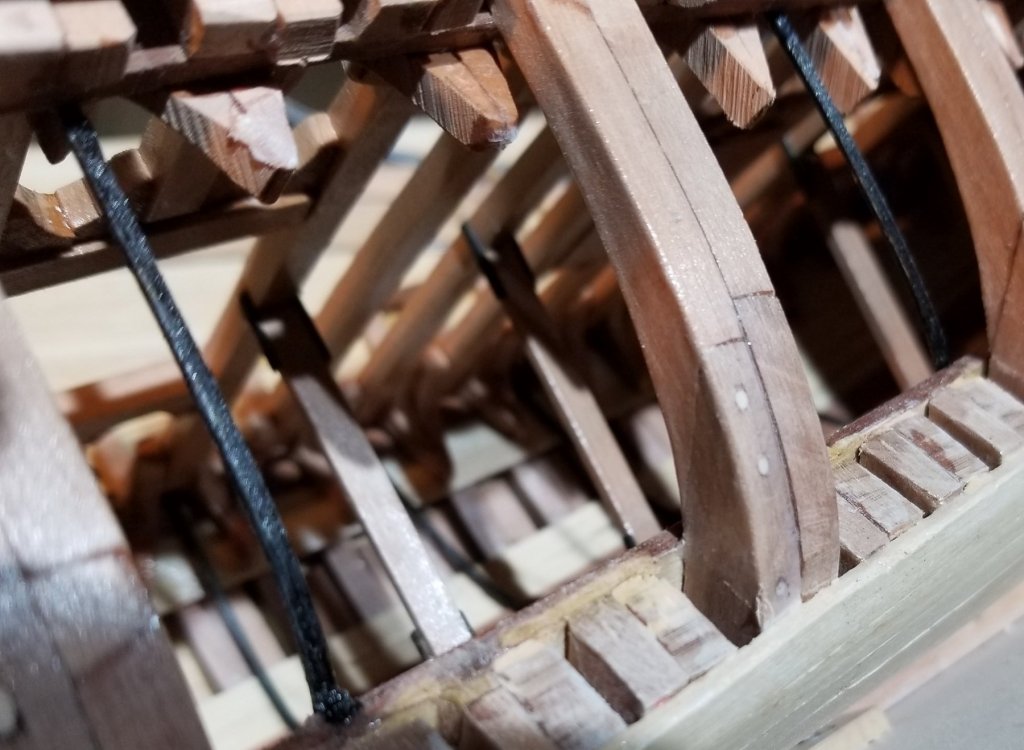
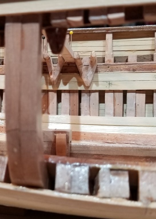
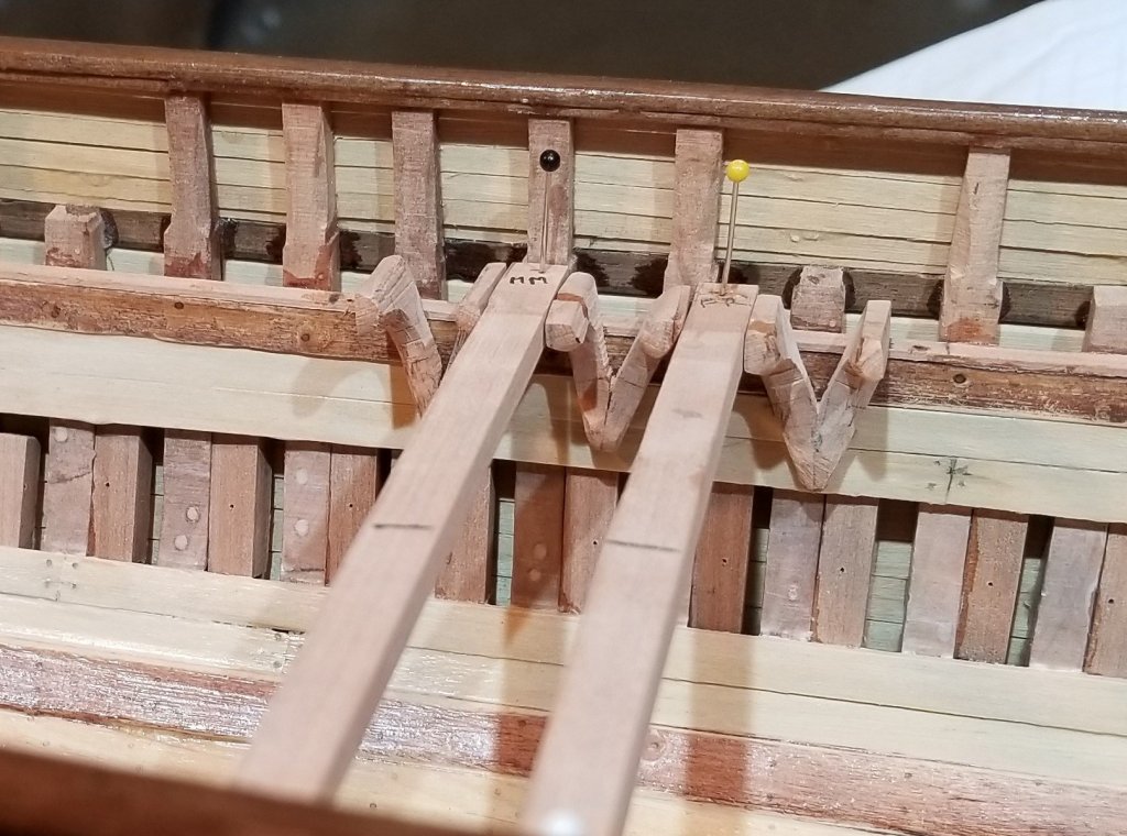
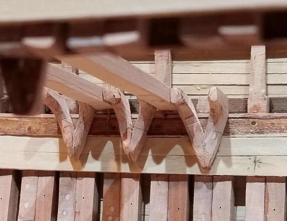
Before discussing the diagonal hanging knees, we'll finish up on the doubling up of the frames to correspond with Leon as described in the 1880 DNV Survey. There are three places, beyond the exposed frames in the 6 ports, that needed attention. At the bottom of each port and at the top of each port short pieces were glued in to represent double framing. Then, on the port side, opposite the 6 ports, little doubling pieces were glued in where 3 ceiling planks were left off. The picture below shows 2 deck beams along with the diagonal hanging knees that support them. The beam marked with a yellow pin head shows clearly how the diagonal hanging knees serve as both lodging knees and hanging knees. This arrangement was discussed in a topic of an NRG forum under the title "An unusual (to me) arrangement of hanging knees and riders on brigantine Leon." Note that knees from adjacent beams are fayed together. We only have a single diagram of diagonal hanging knees (from Norwegian sources) and this is for just one deck beam so we can not see how the knees meet one another. The method used here seems reasonable. It is of note that the 1882 DNV Rules and Regulations describes these diagonal hanging knees as only being acceptable for single deck vessels. It is possible that the arrangement is uniquely Norwegian, or at least that opinion can be held until contradicting evidence is found. As a side note on Norwegian uniqueness, the 1882 DNV Rules and Regulations gives acceptable scantlings for the hold stanchions as 4" to 5" by 8" to 12" - Leon uses 4" by 10". Other references that I have seen for America and England specify square, circular or a near square oblong rectangular cross section. Are there other places that use large aspect ratios like Norway? The next picture is from beneath the deck beams. Lots of work to finish the deck beams and the knees. Doug
- 108 replies
-
- 6
-
-
- leon
- brigantine
- (and 1 more)