HOLIDAY DONATION DRIVE - SUPPORT MSW - DO YOUR PART TO KEEP THIS GREAT FORUM GOING! (89 donations so far out of 49,000 members - C'mon guys!)
×


Doug McKenzie
-
Posts
221 -
Joined
-
Last visited
Content Type
Profiles
Forums
Gallery
Events
Everything posted by Doug McKenzie
-
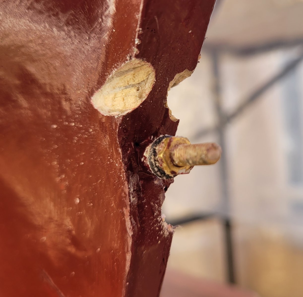
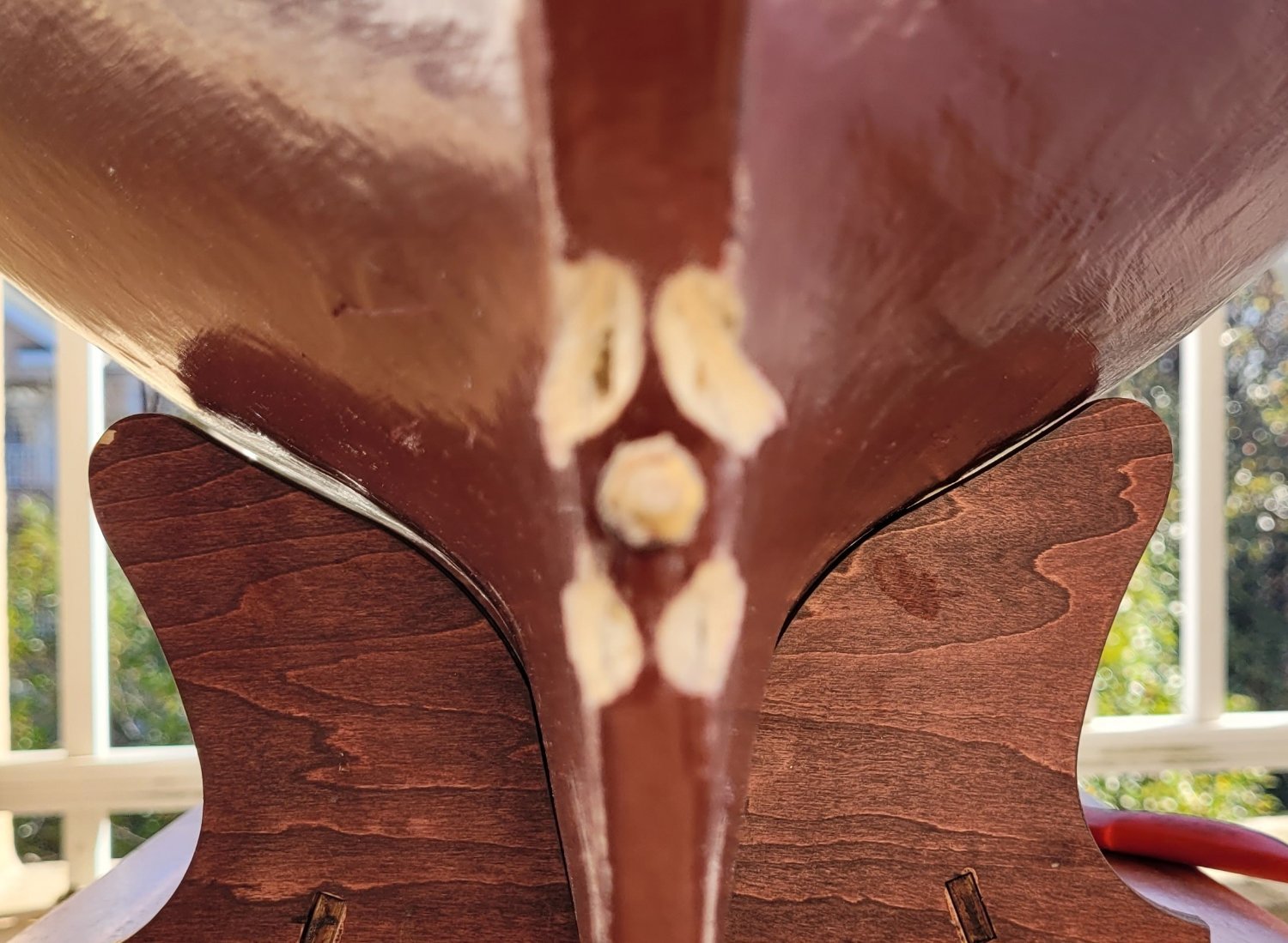
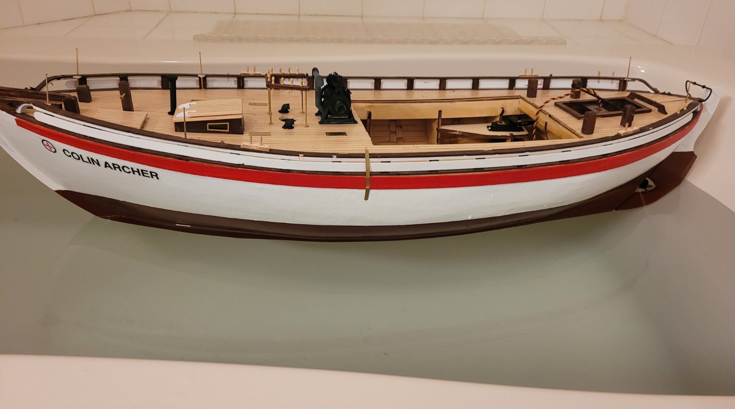
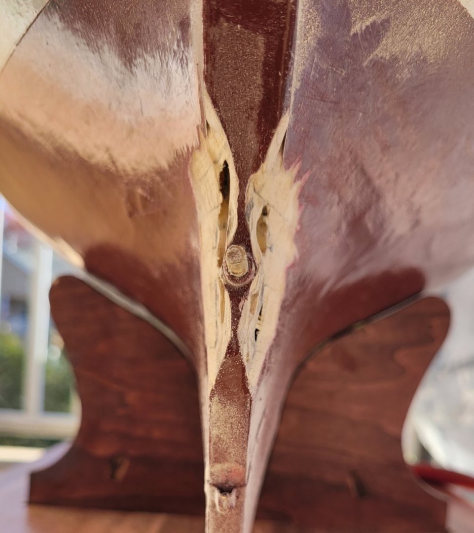
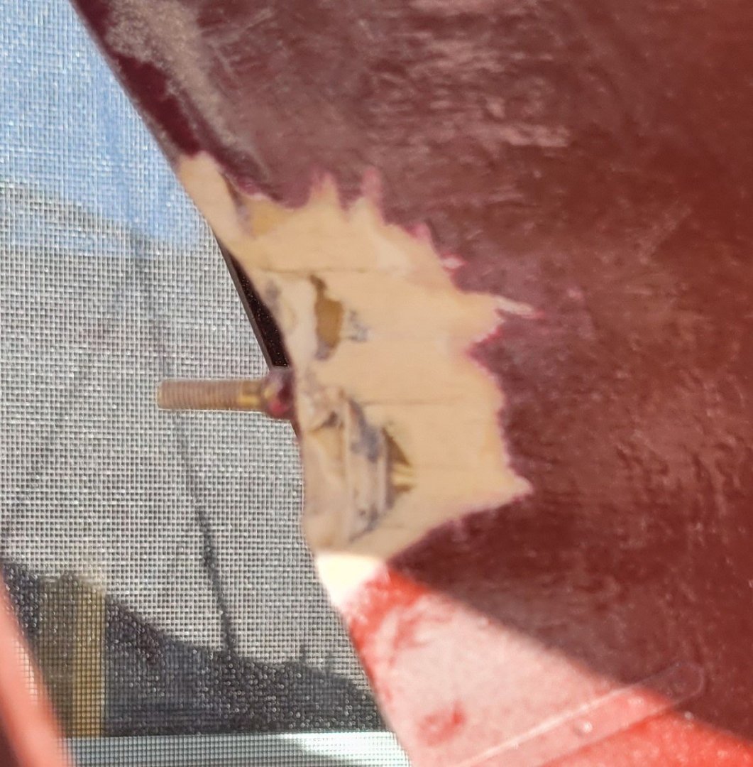
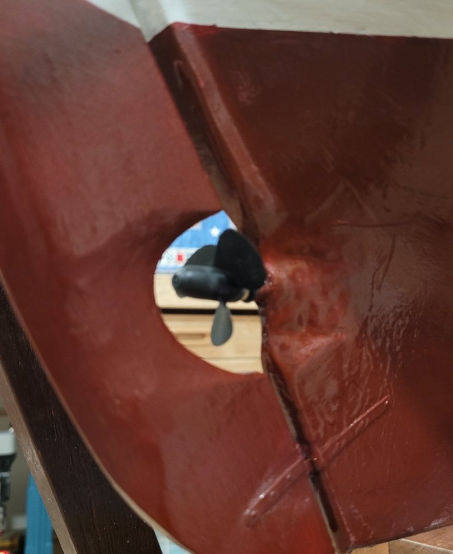
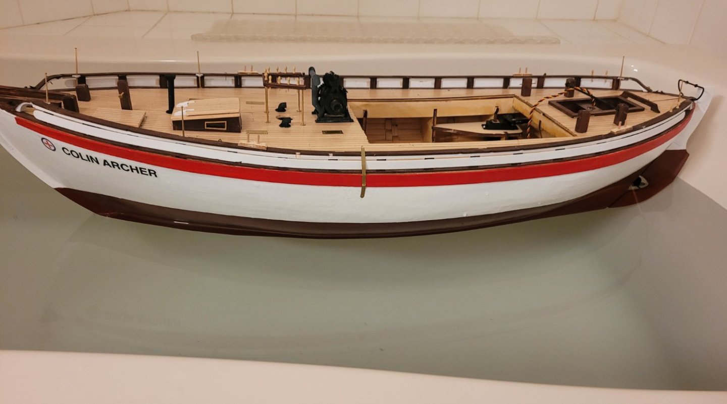
At this point I put Colin Archer on her first sea trial in the tub to see how well the motor worked. It turned out to be sort of pathetic. I estimate a top speed at something like 6 inches per minute (0.006 mph). Hardly enuff to deal with difficult situations on a pond. After a few consultations, I took a good look at the hull around the propeller and noticed that the stern post was quite wide (3/8" to 1/2") in the vacinity of the properlor. Thus the propellor (only 1 3/8" in diameter) was largely churning dead water. I decided to trim the rear edge of the stern post down to about 1/16". Pic 1 shows the situation before trimming with two small gouges at the start of trimming. Pic 2 shows the thinning in progress with the propeller shaft boss emerging. Pic 3 and 4 showing the final thinned result. Having broken through the fiberglass and some planking, some spaces adjacent to a bulkhead are visible. A layer of fiberglass and two additional layers of resin will be followed by 3 coats of paint. The rudder is also being thinned by removing about 1/3 of it's thickness, so it is about 3/16" in the vicinity of the propeller with tapers to 1/16" at the leading and trailing edges instead of the overall 5/16"thickness. Pic 5 shows the completed repair. The quality of the painting is marginal BUT she flies like a jet airplane. I can't make a speed estimate yet because going forward with just a touch on the throttle she tried to climb out of the tub. When she's in reverse she's more stately. Her next sea trial will be in a pool and I'll probably turn the End Point setting down to avoid planing! To say that this repair exceeded my expectations would be a total understatement. One unexpected development - at some point the propeller unscrewed itself. I solved this problem with Strong Locktite. This was quite stupid because 250 degrees will be necessary ro remove the propeller which is plastic! In the next post I learn to use nail polish.


- 56 replies
-
- 2
-

-
- Colin Archer
- Radio
- (and 1 more)
-
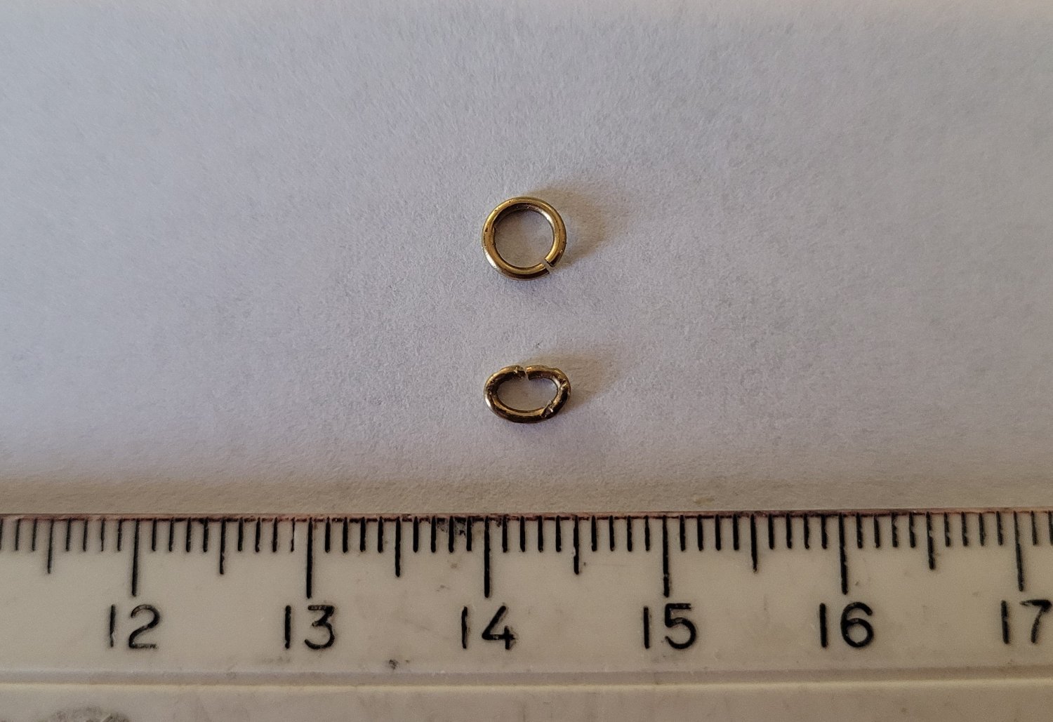
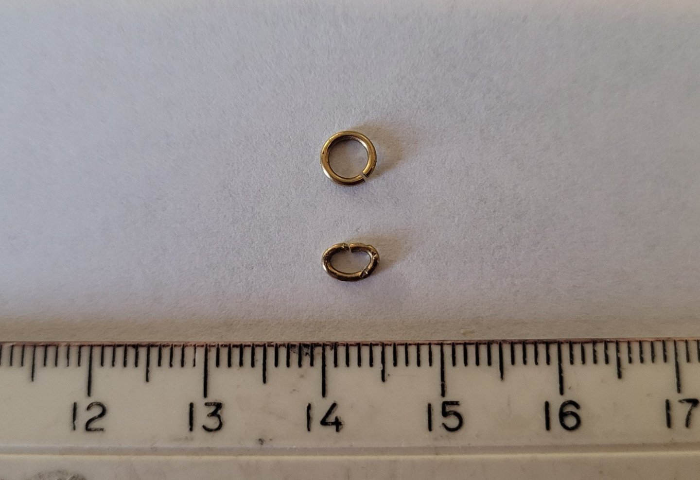
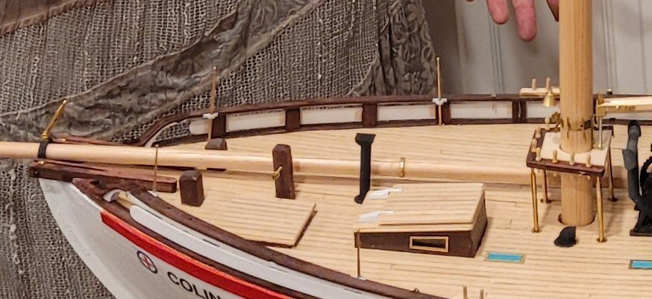
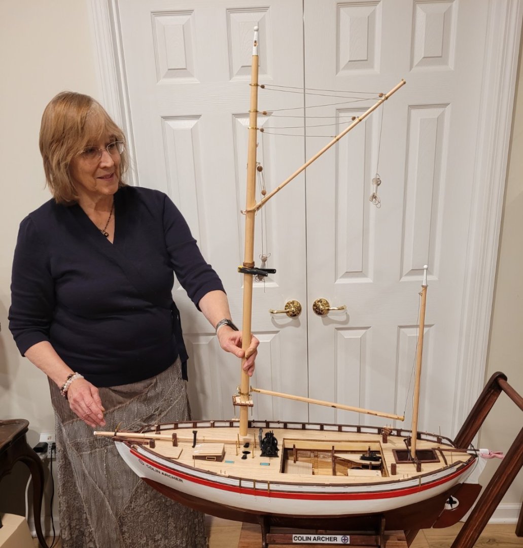
So, last post I said I would focus on the controls for the 2 fore sails next. That is not true. The reason is that I want to get started on the actual control scheme for the sheet of the mainsail. To do that, I need, at the minimum, the main boom in operation. That suggests that the fittings on the main mast need to be finished so that's what I'm going to focus on for this post in addition to the technique I'm using to be able to take the mainmast out of the hull for transportation. Pic 1 shows the rigging for the main gaff. Billings provides cute little plastic shells for the blocks and beautiful brass sheaves. The only problem is that the width of the slot in the shell is less than the thickness of the sheave so there is no way the sheave can rotate. The good news is that the line slides easily even without rotation so no problem. All of the bands are made of thin brass sheet so whenever lines will be attached I worried about abrasion cutting the line. So I introduced something like a shackle (in function) and a link of chain (in appearance) to avoid the problem. BB provides a whole lot of brass rings (I think for the topsail). I cut out about 3 mm and squished the rest into the chain link shape, Pic 2. If the strop of a block is line, I use one of these things. If the strop is steel wire, I don't. On the right of Pic 3, the spider band can be seen which also provides the pivots for the post on the end of the boom - together the pivots and post constitute the gooseneck. At the far left of Pic 3 a turnbuckle (from Harbor Models) can be seen attached to the stem fitting that constrains the retractable bowsprit. This will be discussed shortly when we talk about removing the mainmast from the hull. Now we discuss removing the mast for easy transportation purposes. Pic 4 shows the mast in place. Pic 5 shows the mast lifted out of the hull. The unusual thing about this is that the fife-rail is attached to the mast and stays with it when the mast is lifted up. The reason this happens is that both the standing rigging and the running rigging are involved in allowing the mast to be lifted out. The standing rigging, i.e. the forestay and the 6 shrouds, are obvious impediments and they are dealt with using 3 turnbuckles - one for the fore stay and 1 each for the port and starboard triple shrouds. Using the turnbuckles, allows these lines to be released freeing the mast to be lifted out. This wouldn't work very well with the running rigging - there is too much of it and it doesn't correspond to anything real. But, on this ship all the relevant running rigging, i.e.. peak and throat halyards, fore sail halyards, topsail lines (halyard, sheet and tack) and the flag halyard, lead to the fife-rail. So everything is taken care of by attaching the fife-rail to the mast. This is done with a little 'platform' that is left white so that the real fife-rail is left visible. One thing that I'm a little proud of is how the 4 posts of the fife-rail are handled. All four are cut, of course, but not at the same height. Each cut is 3mm higher than the preceding cut. Brass tubes of equal length are slid over the lower parts of the posts. Then, when the mast is lowered into the hull, the longest upper portion is fed into its tube. When it is securely in place the second longest upper portion is fed into its tube and so on until all 4 are in their tubes and the whole thing slides down. If the 4 cuts were all at the same height it would be hard to line them all up simultaneously.

- 56 replies
-
- 4
-
-
- Colin Archer
- Radio
- (and 1 more)
-
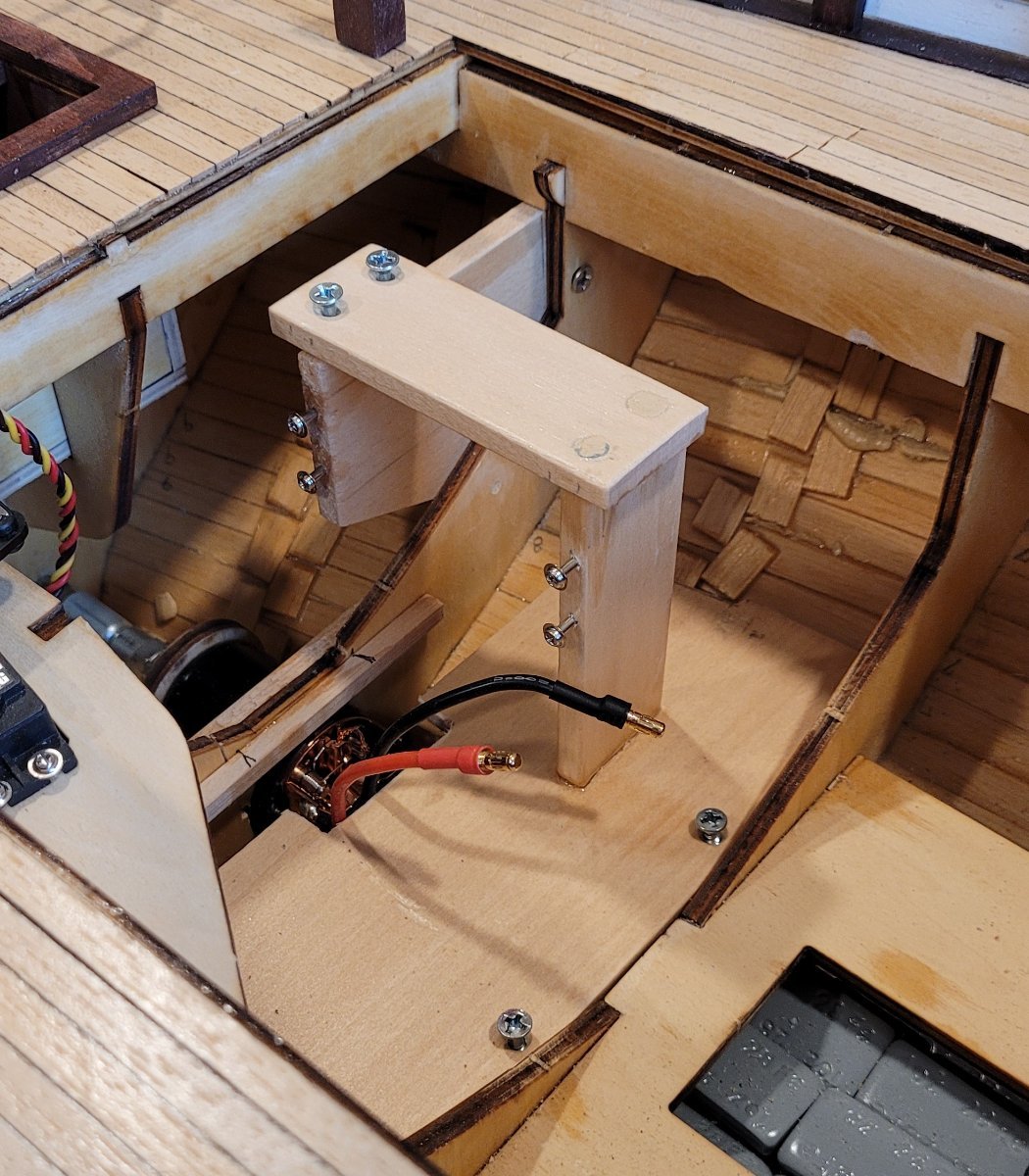
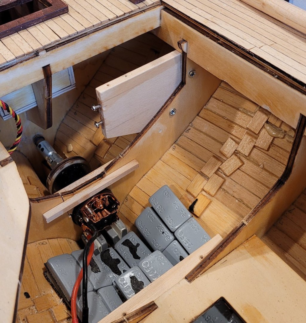
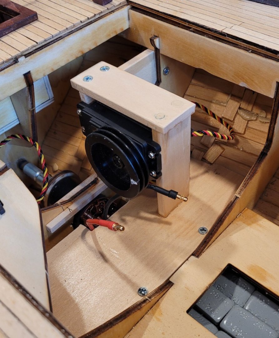
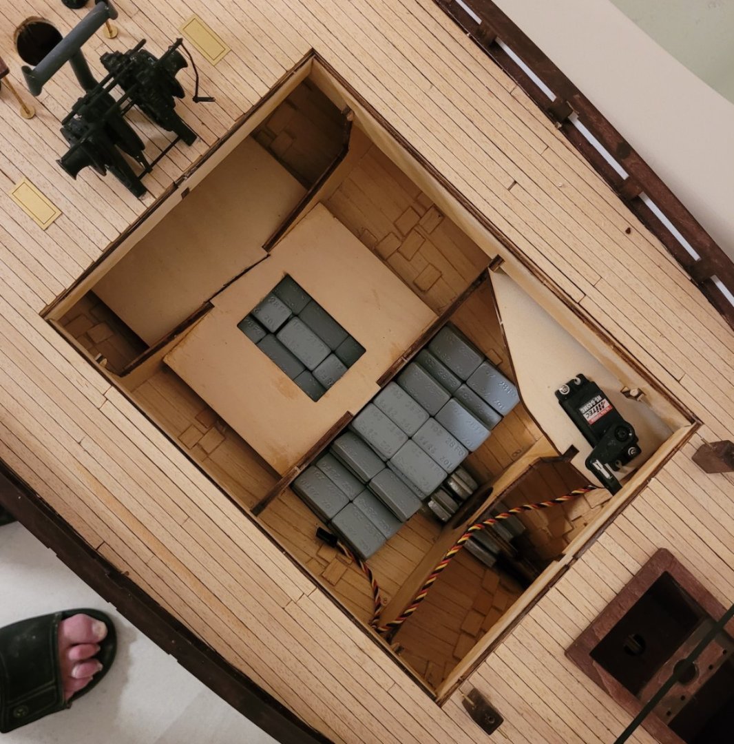
Now for the winch servo that will control the main sheet. This post comes just a few hours after the last post because the motor had to be in place before this work could be installed. The work itself was actually completed a few weeks ago. Pic 1 takes up after the motor was installed but two new holes can be seen in the bulkhead. Before going into the details, I want to comment on the first two controls. BB is very clear that they provide no support for RC installations, however, if you consider the rudder control, you'll notice that they provide a piece of wood on which the servo fits and that piece of wood notches beautiful into two bulkheads. I myself was very appreciative! Then we move to the second control, the motor, and BB is still helpful. There is a piece of wood that screws onto the motor and slips into a notch on the keel. Along with a hole cut in a bulkhead, the motor is correctly aligned with the propeller shaft which is great. Even though I had to move the notch and open up the hole in the bulkhead, BB provided a lot of assistance for this installation. Then we come to the third control, the main sheet winch servo, and the only help that BB provides is a diagram of where it needs to be. I'm not complaining because this is how I learned that the winch drum should rotate around an horizontal axis and that the drum should be roughly on the centerline of the boat so that the main sheet will smoothly pass up through the cockpit to the end of the main boom. I am only pointing this out because of the need to create a structure for the winch servo based on my own experience and creativity was very challenging since I have no RC experience! The structure that I have designed can undoubtedly by much improved on, I just hope it works. One thing I am very glad of is that I realized that I have to be able to disassemble it if the need arises. Pic 2 shows what I am calling a bulkhead doubler because I can't think of another name. Obviously the two holes were for screws to hold the doubler! Pic 3 shows a more complicated addition that has 3 pieces of wood: The lowest piece provides a foundation for the other pieces to which the winch servo for the main sheet will be attached. Note that the little horizontal piece on top, screws into the bulkhead doubler. That makes it really strong. In addition, the lower piece of wood will later provide a foundation for some of the other RC components (e.g. the ESC). In Pic 4 the actual servo is installed. The pictures are a little misleading because it might seem that with the wood structure in place, I just slide the servo in to its place. Unfortunately, it's not so easy. I have to loosen all the screws of the support structure so that it becomes wobbly in order to get the servo into its place and then retighten all the screws. The actual connection to the sail will have to wait until there is at least a main boom but I would like to present my plan for comment. Only a single line will exit the winch. It will pass up through the cockpit and then attach to the end of the main boom. The control in neutral position will have all the line on the winch drum and the sail be in line with the center line of the boat. A little bit of line will be unwound for close haul, more for reaching and pretty much all of it for running. When running, the tip of the boom will be about 17" from its position when the boom is on the centerline. The servo will be able to release about 15" of line with 3.5 revolutions of the drum - 17 & 15 are close enough for engineering work (I think). Of course, a possible problem is that if the wind does not cause the sail to keep the line reasonably taut as it is released from the winch, it could get tangled - not good. One possible fix for this is to run the line up the mizzen mast through a block, to a weight, then down to a fairlead at the level of the boom and then to the boom end. This would allow the line coming off the winch to be relatively taut and extra line could lie in a bight in free space where it would be unlikely to tangle or catch on anything. Any comments would be welcome. Later we will see that the 2 controls operating on the staysail and jib sheets will not have this problem because these sails both have two sheets and when the winch releases one sheet , it will take up the other at roughly the same speed therefore the whole loop will remain more or less taut enough to avoid tangle. A real advantage to this arrangement is that the foresails can be back winded if needed. Next post will be the controls of the foresails and again BB has some helpful diagrams but the implementation is left up to the modeler.


- 56 replies
-
- 2
-
-
- Colin Archer
- Radio
- (and 1 more)
-
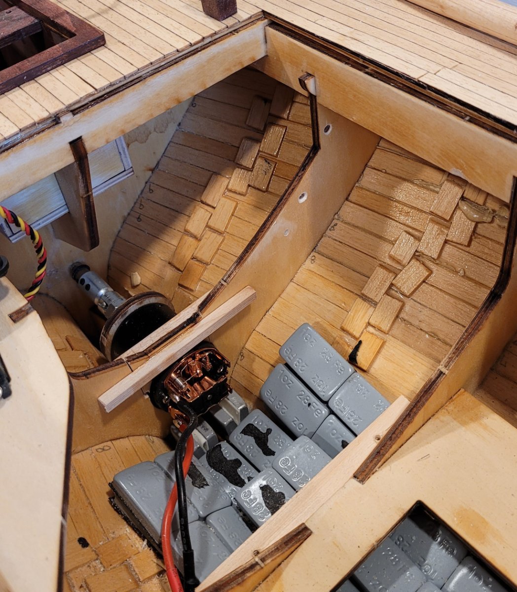
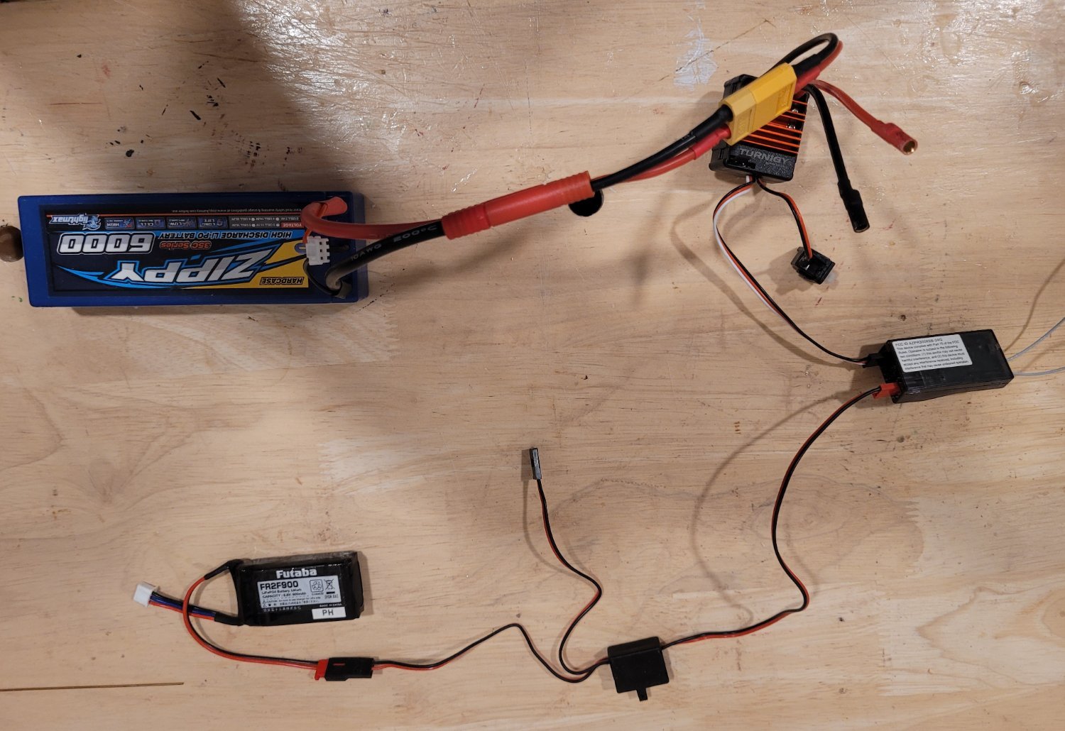
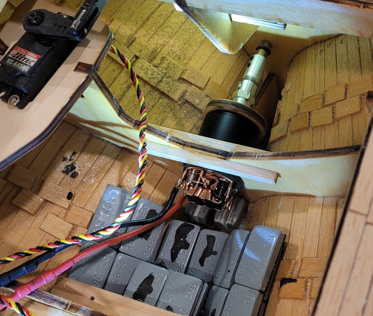
Now for the motor. In Pic 1 the motor is in place with the coupler joining the propellor shaft and the motor shaft. A few comments on the motor: 1-- It is a TURNIGY TRACKSTAR 540-13T BRUSHED MOTOR from Hobbyking. How did I arrive at this motor? The tech service guys at Hobbyking directed me to a different motor but it was unavailable. They then directed me to this motor in combo with 60A ESC COMBO FOR 1/10TH CRAWLER. Notice that I have no idea why these recommendations were made nor why the two motors (I guess) are equivalent. I'm very glad that the tech service guys did not try to explain any of this to me. 2-- The coupler comes from Octura Models that my local hobby store manager told me to contact. They serve the motorized boat model community. The coupler is a universal joint that allows for a little misalignment between the propellor shaft and the motor shaft. The coupler expected both shafts to be 1/8" in diameter. This was true for the motor shaft but not the propellor shaft which was a little smaller. I inserted a brass tube with 1/8" OD (and an ID smaller than the propellor shaft) into the coupler and drilled the ID to fit fit the propellor shaft. The remaining wall thickness was sufficiently thin that the set screws had no trouble clamping everything together. 3-- The coupler was too long for the position of the motor support that Billings provided so I had to reposition it about 3/8" further from the propellor shaft. The motor support can be seen between the motor and the coupler. It is screwed onto the motor. Installing the motor required cutting the bulkhead that also supports the motor. Then the piece that was cut out is replaced as shown in Pic 2. Starting from the lower left of Pic 3, I describe the RC components for the motor. The Futuba battery that drives the receiver, the receiver switch and the receiver itself have all been discussed previously in connection with the rudder control. Then comes the ESC (identified earlier with the motor) with a little switch, the two leads to the motor itself. Lastly, the motor battery, ZIPPY 6000MAH 2S2P 35C HARDCASE PACK. In between the ESC and the battery is an adaptor. I only mention this because the first adaptor that I got was not correct and the ESC billowed LOTS of smoke. Hobbyking diagnosed the problem and sent me the correct adaptor and everything worked fine after I replaced the ESC (eBay) also. The first adaptor I got from a hobby store. It is not clear to me whether there are two versions of this adapter or whether the first one was a mistake. It turns out that the little switch on the ESC doesn't seem to do anything. It is supposed to turn the motor off but Hobbyking says a lot of people don't use it and some ESCs don't even have the switch. Also, the switch for the receiver has 2 wires coming out of it that I have no idea what they are for. One last comment is that in the transmitter, I used the "End Point" function so that the full range of motor speeds is not used. Currently, it is set at 50% for both forward and reverse. I may change that after sea trials. Next post will be about the winch servo used to control the mainsail sheet.


-
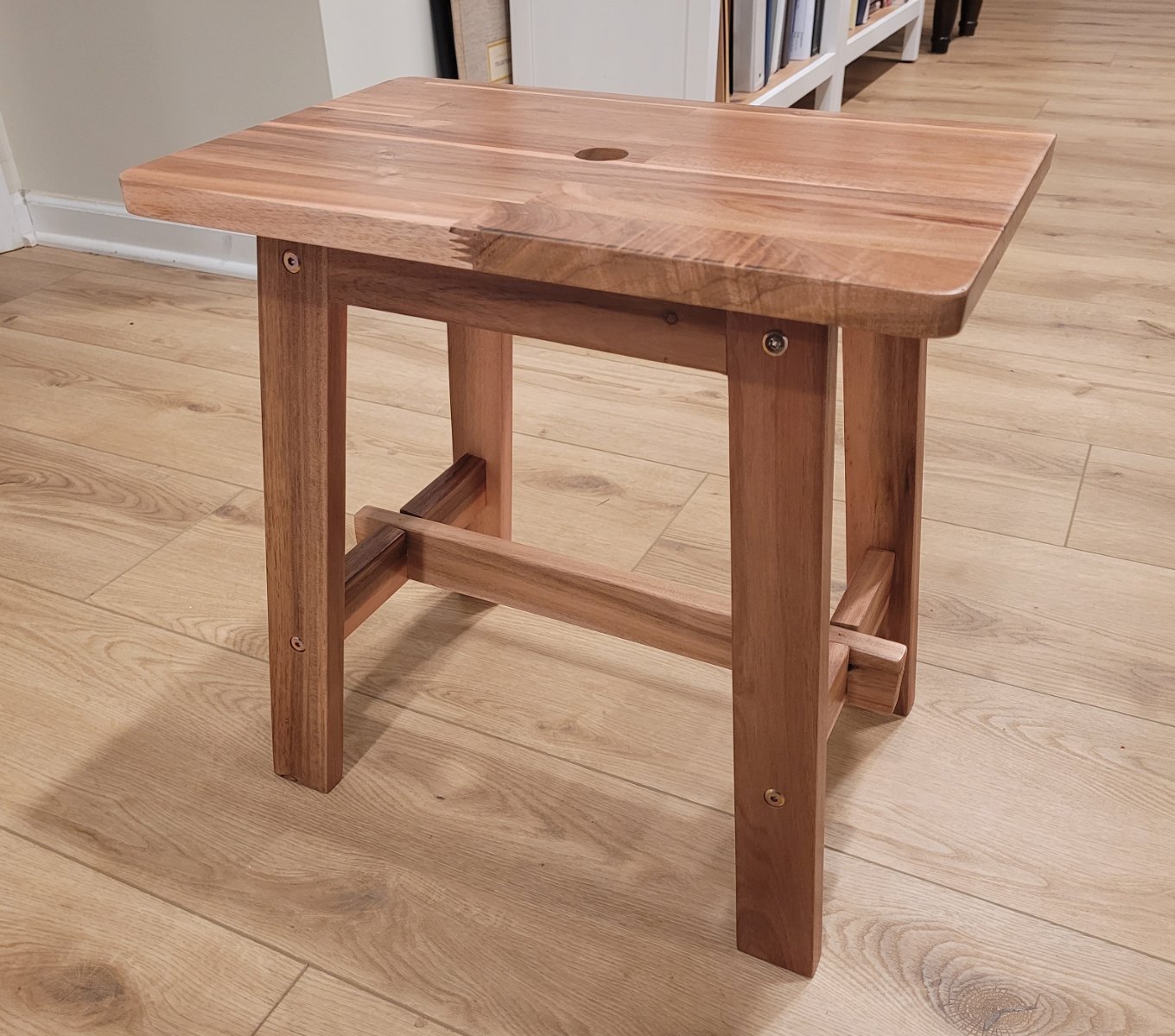
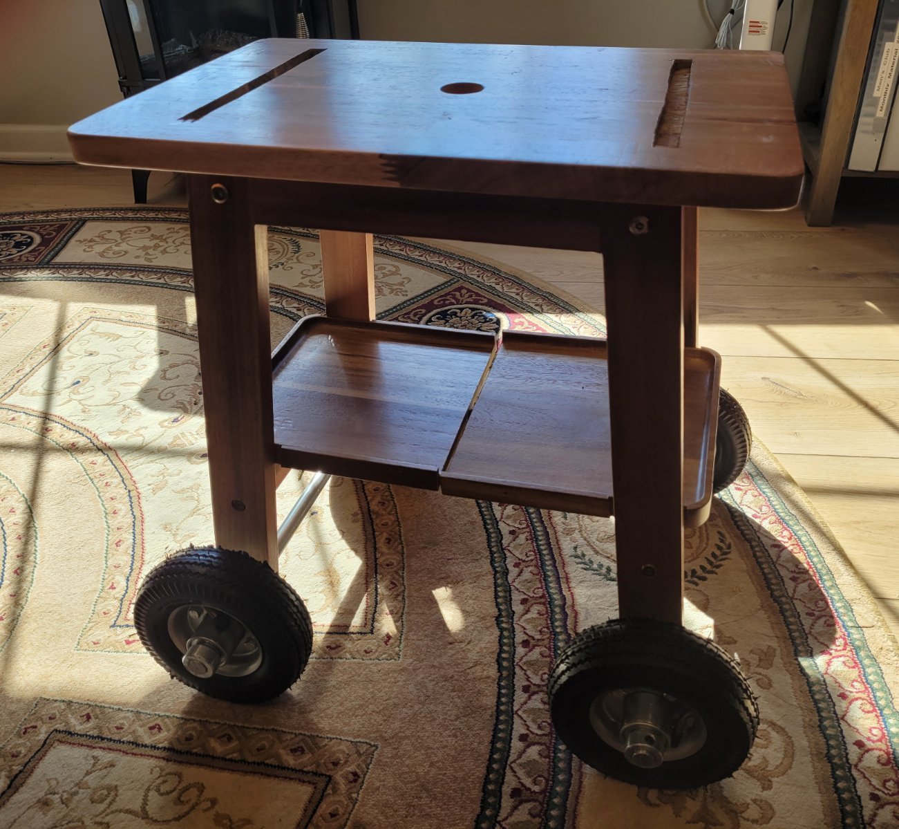
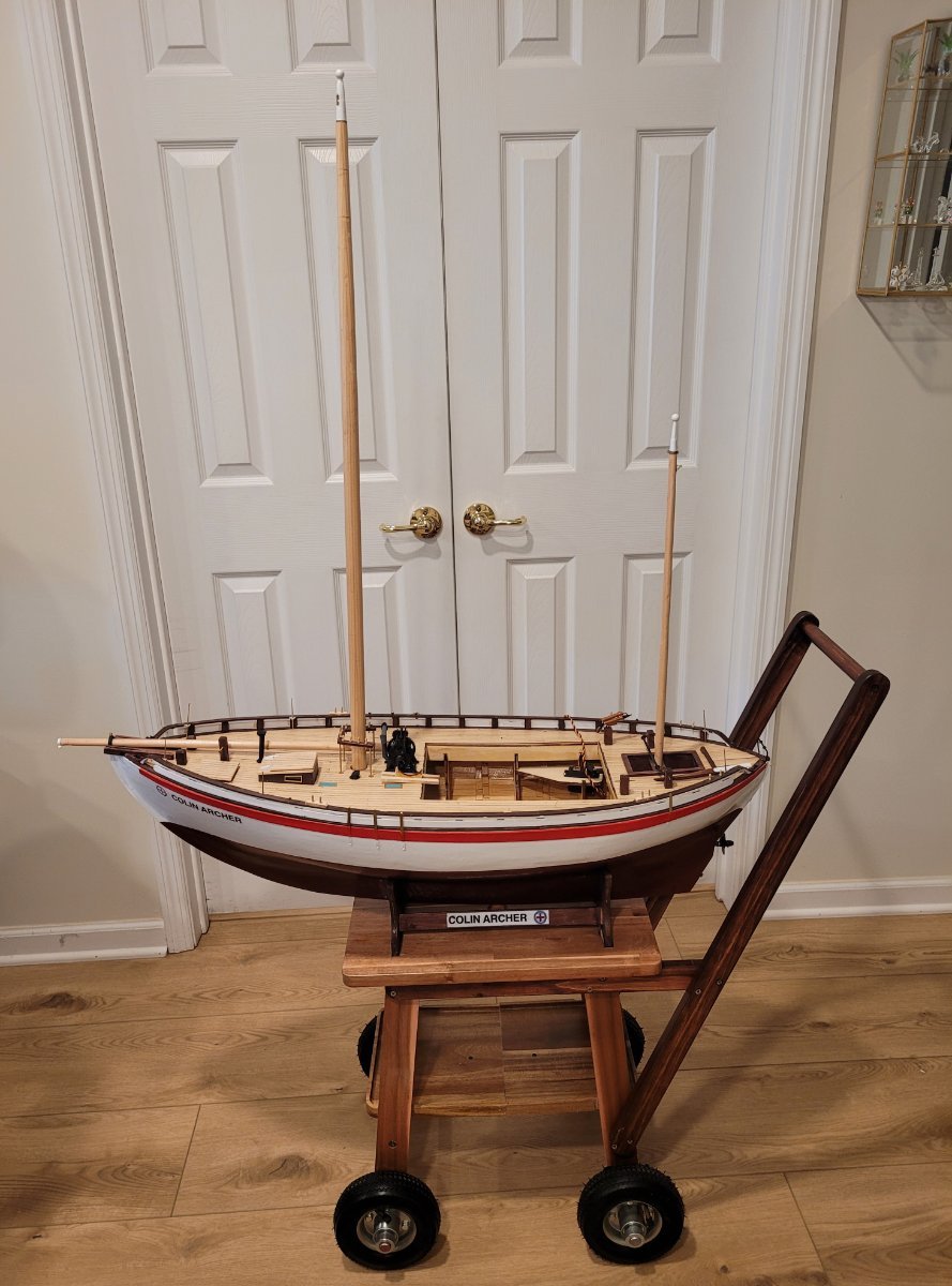
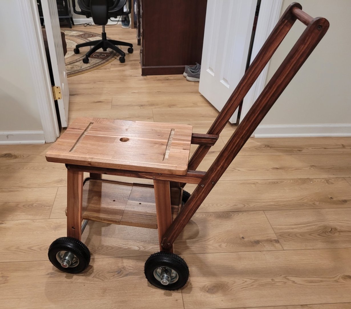
In this post, I show the cute little cart that will transport Colin Archer around in my workshop and on the grass. It started with a table from Amazon 18" long, 18" high and 12" wide (Pic 1). I did have to make one modification to support a shelf - the long bottom bar, in the original stood 3/4" higher than the side bars. I cut 2 dados in the long bar so that the tops of the 3 bars would be flush. The wood is acacia, really quite beautiful. Then a shelf was added sitting on top of the 3 bottom bars. Amazon had serving trays made out of acacia that were just a little too big but were able to be modified (Pic 2). This was more challenging than it may appear because the legs are splayed out in both directions whereas they look vertical in the pictures. The four wheels, each 6" in diameter, are mounted and two shallow grooves on the table top will secure the mounting cradle. I have to thank my friend, Marty, for reminding me that I should uses tubed tires rather than solid wheels so that the cart will roll much better over rough ground and grass. Also, I thank him for the use of his tools (e.g. Sawzall with a metal blade for cutting the 5/8" steel axles) - He lives in a house, I live in an apartment. The last part of the cart was the handle. When I asked the guy at the hard wood lumber store for a 12' piece of acacia 1x2 he laughed and said, "I don't have any acacia and if I did it certainly wouldn't be available in 1x2." I settled for clear pine 1x2, stained it mahogany and gave it 3 coats of varnish (Pic 3). Pic 4 shows Colin Archer sitting proudly on her new cart. The bowsprit is in the retracted position as it would be for transport. The two masts will be horizontal during transport but that story will come much later. In the next post, I'll get back to the RC components focusing on the motor, the ESC and the battery.


- 56 replies
-
- 5
-
-
- Colin Archer
- Radio
- (and 1 more)
-
I'm making a separate post for a question. Putting the boat in and taking her out during the ballast runs made me realize that this thing is going to be way too heavy and cumbersome to be carried so I would like to build or buy a suitable stand/transporter. I'll be making both masts removable so they can lie on the deck. The bowsprit is already retractable. Does anyone know of anything like this that I might be able to use as a starting point?
-
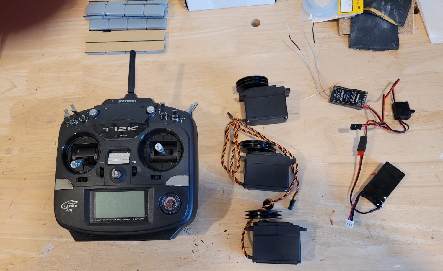
A bunch of deck fittings have been added such as the anchor winch, some ventilators and the deck level light gatherers (dllg's - my name). The dllg's still need to be painted a light blue. These are shown in Pic 1. On to the RC equipment. I have been surprised at the huge selection of RC stuff but little info on what the specs all mean so picking the equipment has been a very human affair. I am going to tell which equipment I'm using and why I picked it since it might be useful to some one. First, I selected the 3 winch servos for the sails and the rudder servo based on their dimensions. Billings provides diagrams of the equipment but no names or models or companies. The winch servos, in their diagrams, matched the HiTec servos HS-785HB and their rudder servo diagram matched the HiTec HS-645MG. That was relatively easy because not too many companies seem to make winch servos. I figured that I would get all the rest of my components from HiTec until I learned that they don't make the transmitters and receivers. I should point out that I got great technical consulting from HiTec and decided that that would be a big factor in choosing the transmitter / receiver vendor. Futuba technical support spent several hours on the phone with me explaining stuff and I finally settled on their 12K transmitter and R3008SB receiver. The 2 key issues for me were 1) the combo could handle the 5 channels that I needed (wanted) and 2) that there were slider switches on the sides that I thought I could effectively use for the jib and staysail sheets. I dealt with 3 different technical service fellows, all great, and one was even a sailor which was hugely useful because all of this equipment is for airplanes and helicopters and the documentation reflects that fact. Until I got used to the RC technical language (underneath the airplane language), the material was not so easy to understand. I choose the Futuba FR2F900 battery to drive the receiver. This one is on the small side, I think, because I don't anticipate long sessions of use. All of these components I've discussed are shown in Pic 2 except the rudder servo which is already installed in the boat and can be seen in Pic 3 & 4. Now to the ballast. The plans indicated that about 6 kg or 13 lbs would be needed. I used 1oz steel ingots that came in 4oz strips with adhesive on the back. They're used for balancing car tires. I wanted to spread the ballast as far forward and aft as possible to reduce completely unrealistic pitching. Pic 3 shows the first 42 oz (of a total of about 200) installed and coated with epoxy. This is just 2.6 lb. You can also see the rudder servo (which is connected to the rudder and works!). After this first batch of ballast, the waterline at the bow was 5 cm above the surface of the water and at the stern it was 5.5 cm above the water (Pic 4). Two other batches of ballast (for a total of 11.1 lbs) have been installed (Pic 5) and the WL is 1.9 cm above the water at the bow and 1.1 cm at the stern. I haven't decide whether I'm going to leave 1 cm of the bottom paint showing or not. Probably I'll see how she sails with 1 cm showing and then make the final decision. Also I need to finish the spars and sails and the RC installation before adding the last bit of ballast. In a chamber, just forward of the mainmast, I was able to insert 2.5 lbs relative to the earlier comment about pitching..


- 56 replies
-
- 3
-
-
- Colin Archer
- Radio
- (and 1 more)
-
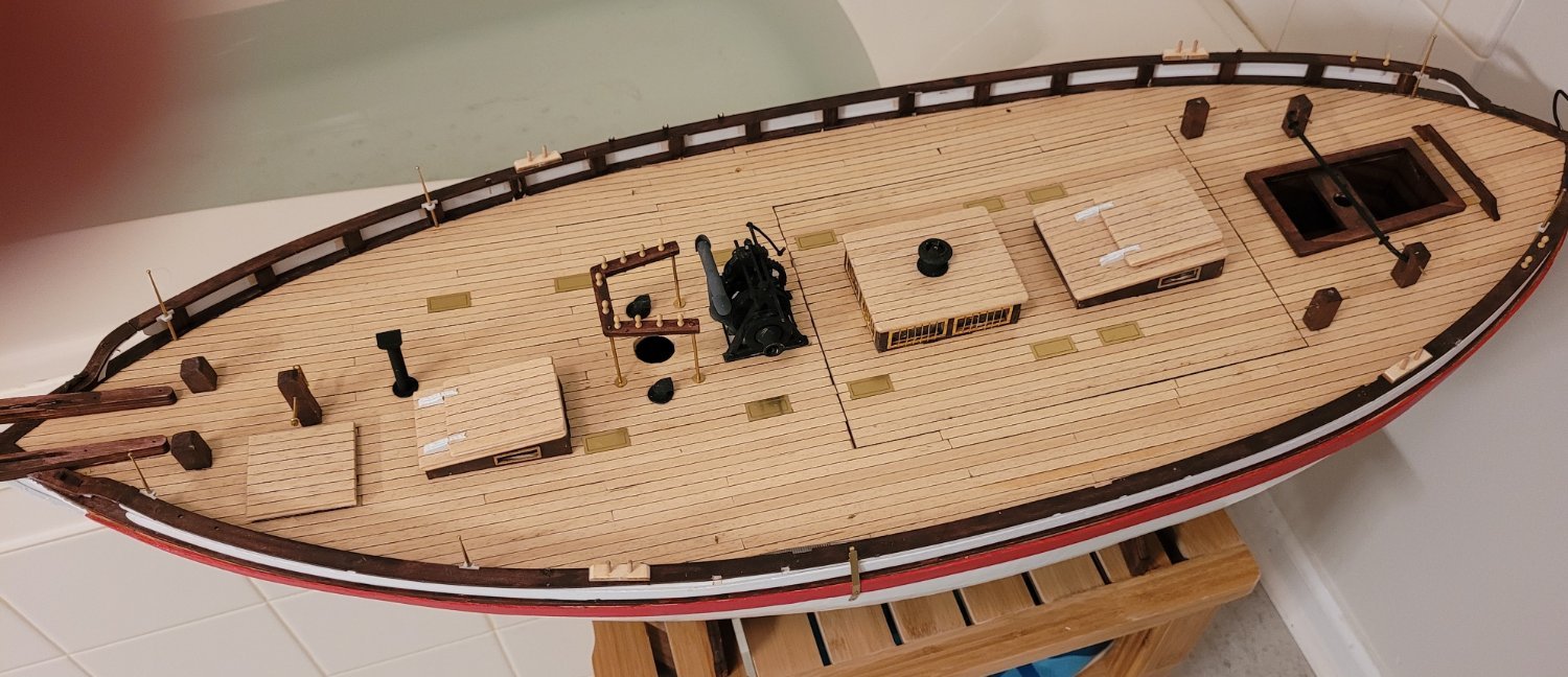
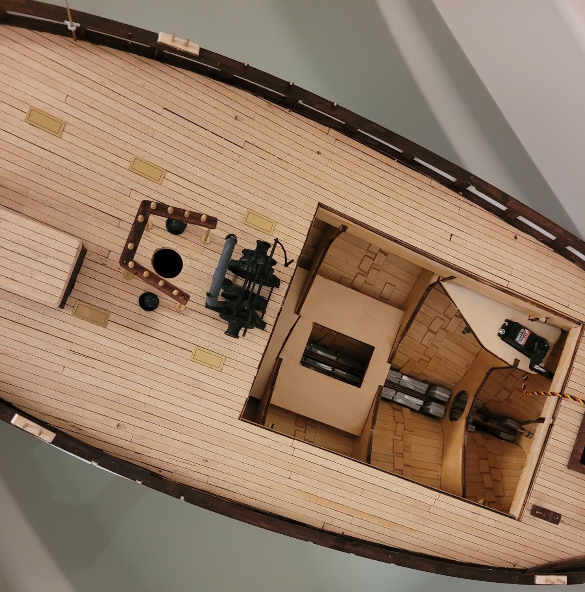
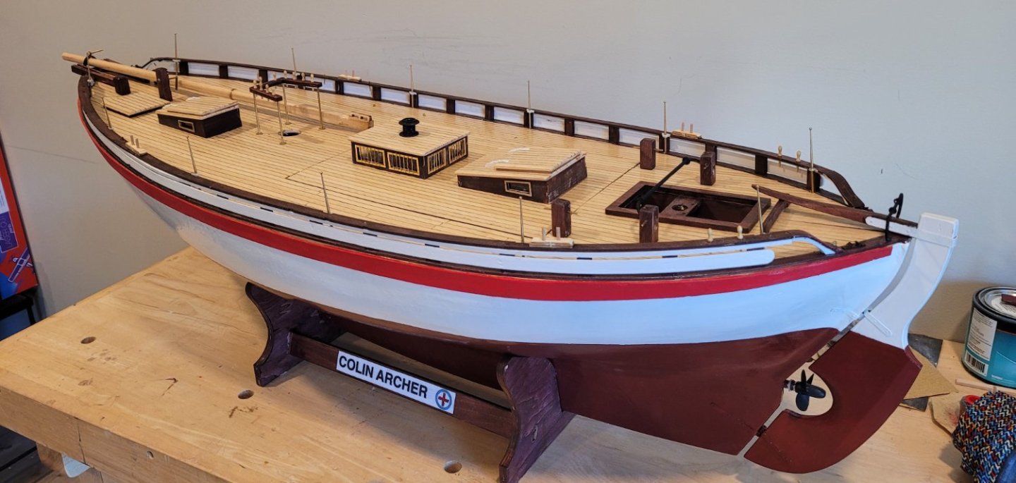
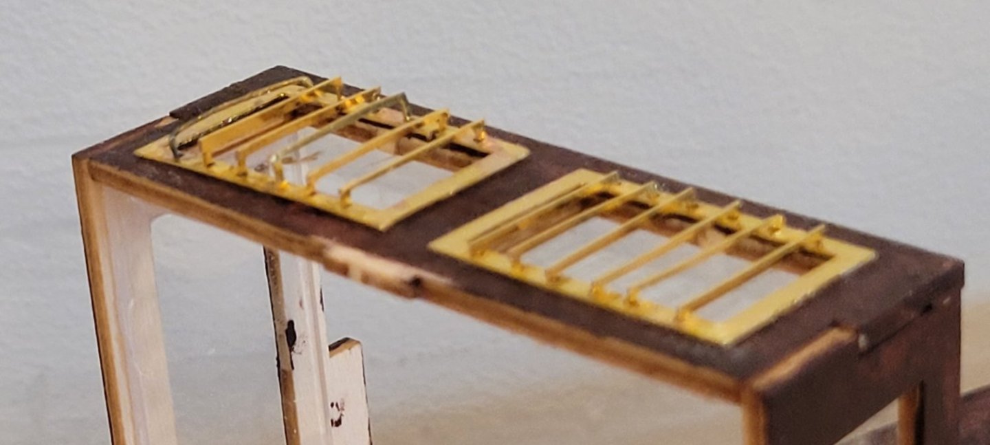
We had an arts and crafts show at the adult community where my wife and I live yesterday. Since I had progressed to the point where I was fitting out the desk I was motivated to finish a bunch of the details so she looked pretty. Thus Pic 1. Installing the stanchions and the fife rail was made easier by drilling a shallow dimple in the deck for the foot of the posts. The rudder is shipped. I'll be fastening a pivoting brass shoe for the bottom of the rudder, connecting it to the bottom of the sternpost in order to prevent the pintles from rising out of the gudgeons when sailing. It may be silly, but better safe than sorry. The travelers for both the main and mizzen were attached to their supports differently than in actual practice. In actual practice, the ends of the travelers were flattened, drilled and bolted. I drilled holes in their supports and inserted the ends of the travelers into the holes. Oarlocks and belaying pins have also been positioned on the rail and fife rail. The window bars on the coach roof posed a problem as they came out very uneven at first try (Pic 2). On the left, there were only little marker holes to show where the bars attached to the frames. On the right, I drilled larger holes to actually accept the legs of the bars. The only authenticity that I lost using this technique was that the bars were closer to the frames. The good part is that they are MUCH more uniform. My favorite fitting is the stemhead fitting that the bowsprit slides through when being retracted and extended (Pic 3). During the yacht phase of RS1 this fitting was served presumably to avoid damaging the bowsprit when sliding in and out. Another fitting that was added during the yacht phase was the ventilator on top of the coach roof.

- 56 replies
-
- 6
-
-
- Colin Archer
- Radio
- (and 1 more)
-
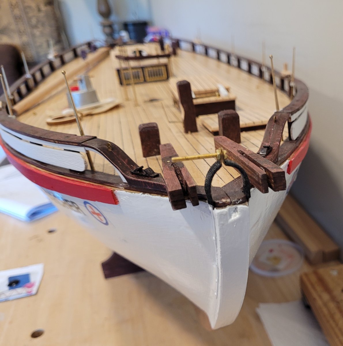
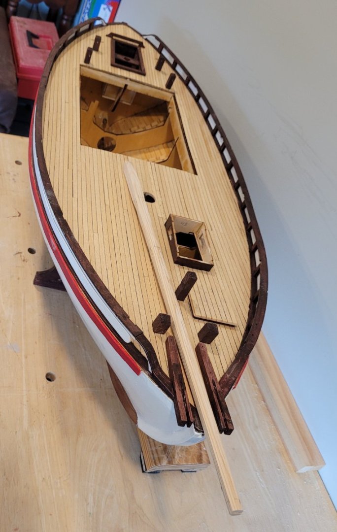
Pic 1 shows the completed rail, the rudder lock (I don't know what this does), 7 posts, the forward hatch and the two anchor cranes. Also shown is the almost circular bowsprit in its retracted position. Now we start the rudder. The kit does not indicate that the after edge of the rudder should be tapered but that seems odd since the rudder is almost 5" thick (full scale). I checked photos from the replica rescue ship Emma and the upper two thirds of her after edge was tapered so I followed that as shown in Pic 2. Then I noticed that the diameter of the prop is only 3 1/2 times the thickness of the rudder which means about 1/3 of the propeller's flow would be hitting a flat wall instead of smoothly flow on. I therefore decided to taper the forward facing edge of the rudder port. This is shown in Pic 3. I think this should make the propellor more effective although the problem still exists for reverse since I am not tapering the sternpost! When fitting the pintles and gudgeons, the kit does not indicate that the upper and lower pintles are in line with each other. I am changing the orientation of the upper pintle-gudgeon pair so that they are in line with the lower so that I can remove the rudder without causing any damage. Another post will show the results.
- 56 replies
-
- 2
-
-
- Colin Archer
- Radio
- (and 1 more)
-
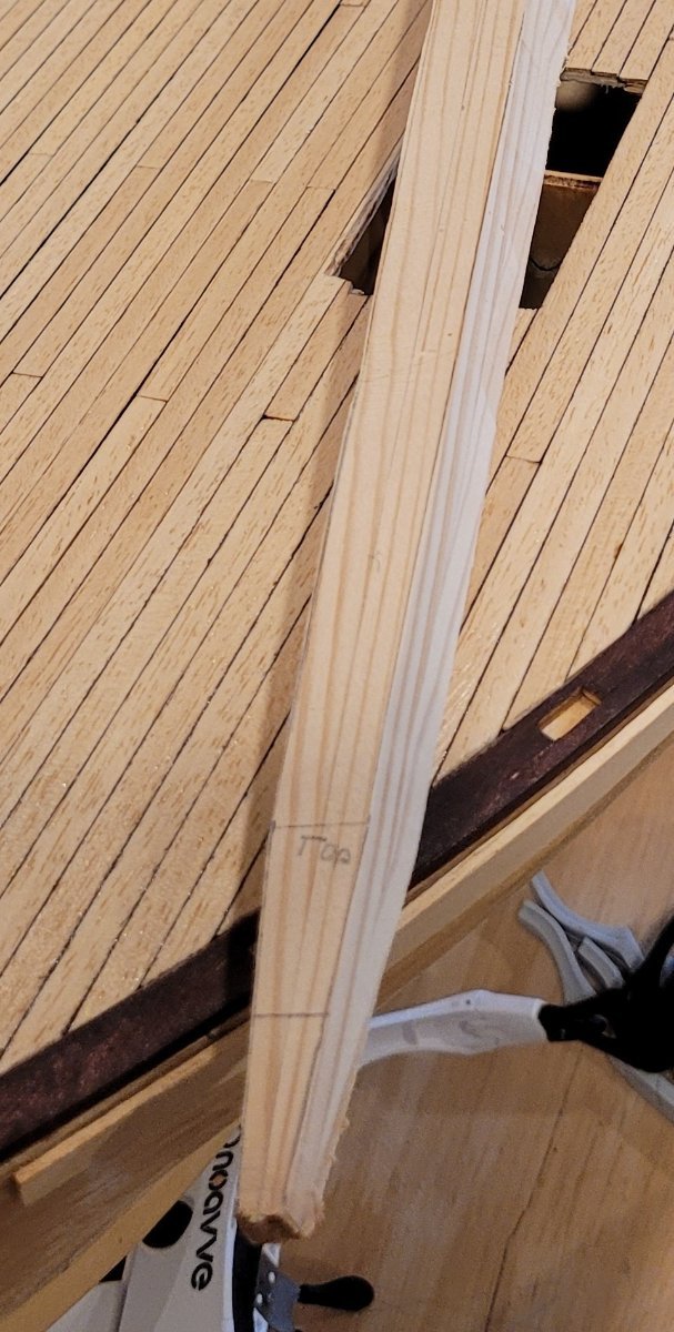
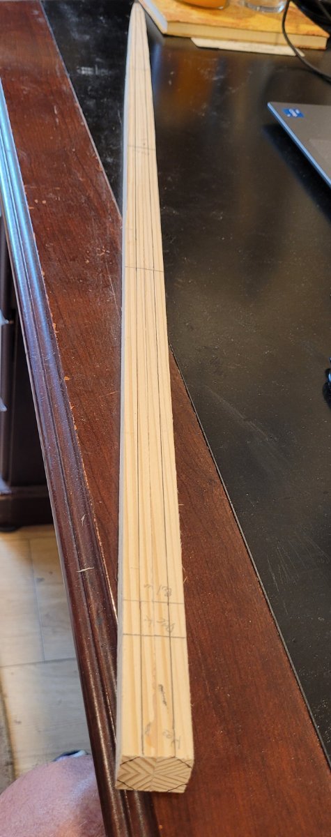
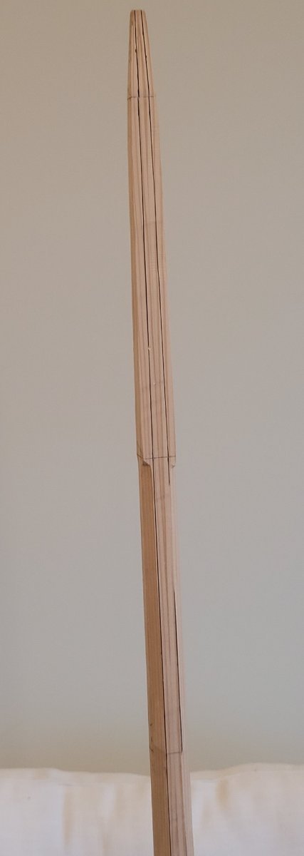
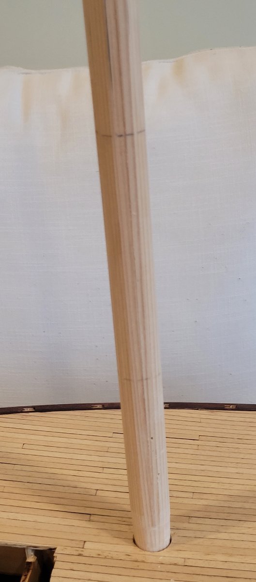
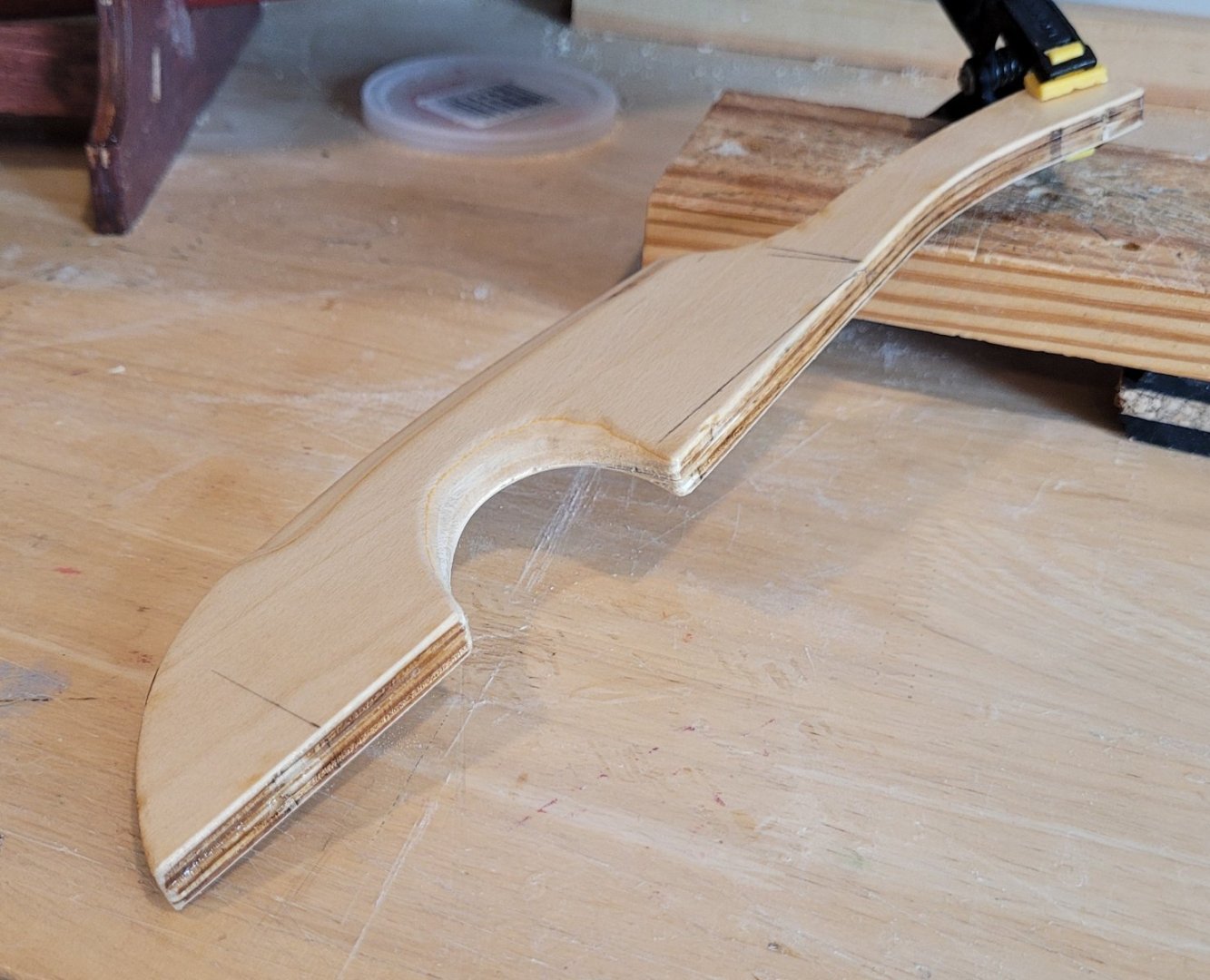
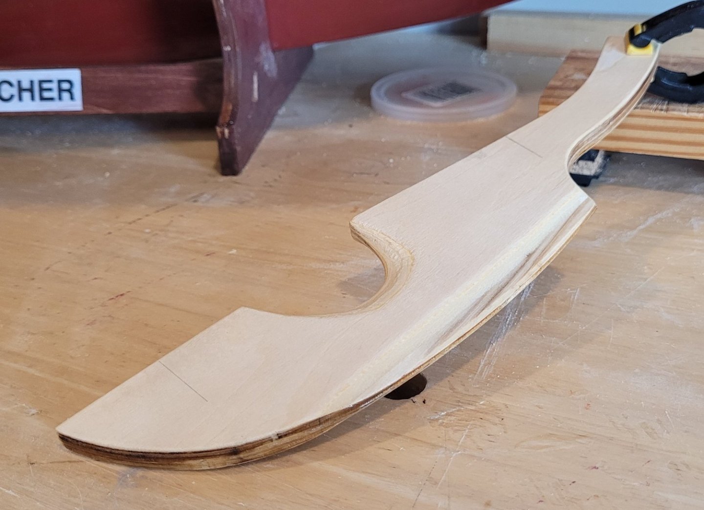
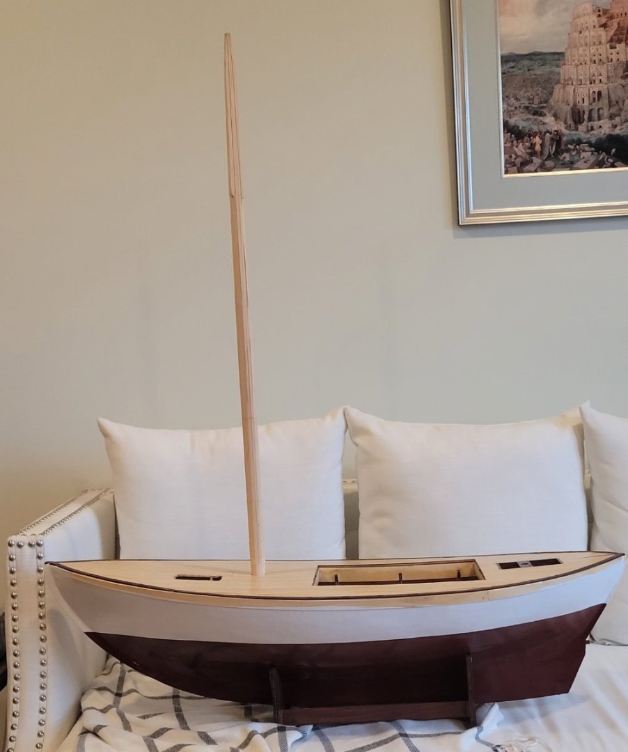
2 sides of the mainmast have been tapered with a small band saw (Pic 1). [BTW the sanded, varnished deck is also seen in this pic. The magic marker method for caulking is clear enuff but certainly doesn't reproduce the actual appearance in the photo in the previous post.] After sanding the sawn sides, the other two sides are marked for taper and sawn and sanded. When the tapered, square cross section is complete, the lines for making the mast 8 sided are drawn (Pic 2). The octagonal shape that will result can be seen on the heel. Pic 3 shows the 8 sided mast that derives from removing the corners of the 4 sided mast. The upper part of the mast is still 4 sided because I'm exhibiting RS1 Colin Archer at an Arts & Crafts fair and I want to show the process for making the mast. The lower part of Pic 3, shows the 8 sided part, you can see the 'ring' around the mast where the lines are visible on the original 4 sides but the 4 new sides are blank. The 8 roughly equal spacings shows that the cross section is octagonal. Pic 4 shows the section below the octagonal part which has been reduced to 16 sides. Another ring is shown with lines on the original 8 sided mast and spaces on the new 8 sides. Again, we're looking for these to be equal. The part below the deck has been rounded. Eventually, of course, the entire mast will be rounded. Pic 5 shows the mast stepped (temporarily) into the painted hull!


- 56 replies
-
- 2
-
-
- Colin Archer
- Radio
- (and 1 more)
-
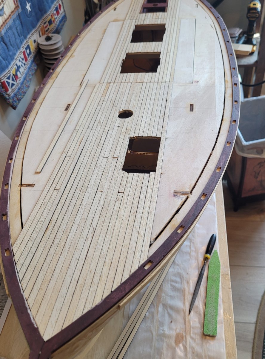
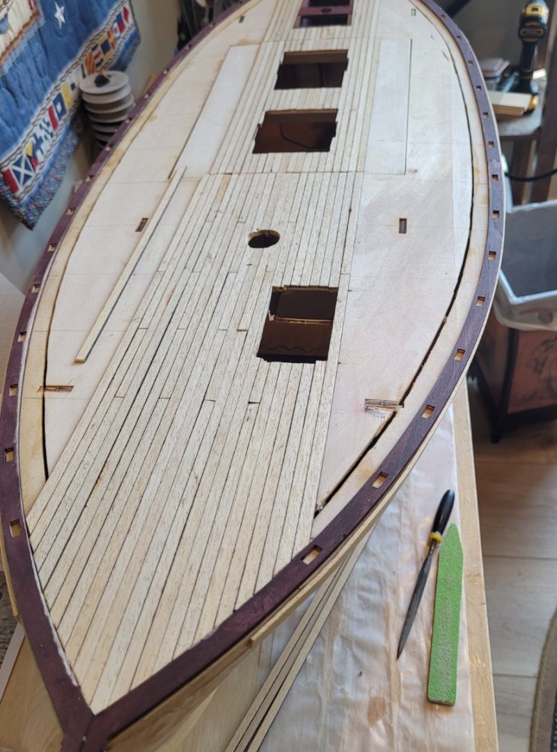
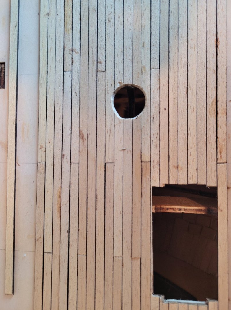
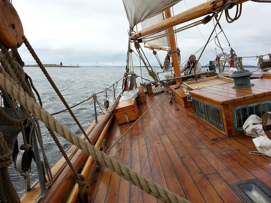
There is something very satisfying about laying the deck planking. Both edges of the planks are colored black with a magic marker to simulate the caulking (Pic 1). It is unclear if that will be enuff, after sanding, to well represent the real thing (Pic 2 from colinarcher.no) - probably not but... The kit provided 3.5" wide planks which is quite close to the real width in Pic 2. I assumed the distance between deck beams was 36" and that they would use planks between 8' and 25' long. The 'deck insert' interfered with normal butt placement but being able to remove the insert was way more important than butt spacing! With these constraints, three planks sit between butts on the same 'deck beam' (Pic 3).
- 56 replies
-
- 4
-
-
- Colin Archer
- Radio
- (and 1 more)
-
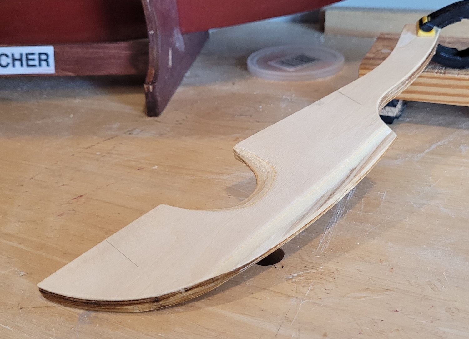
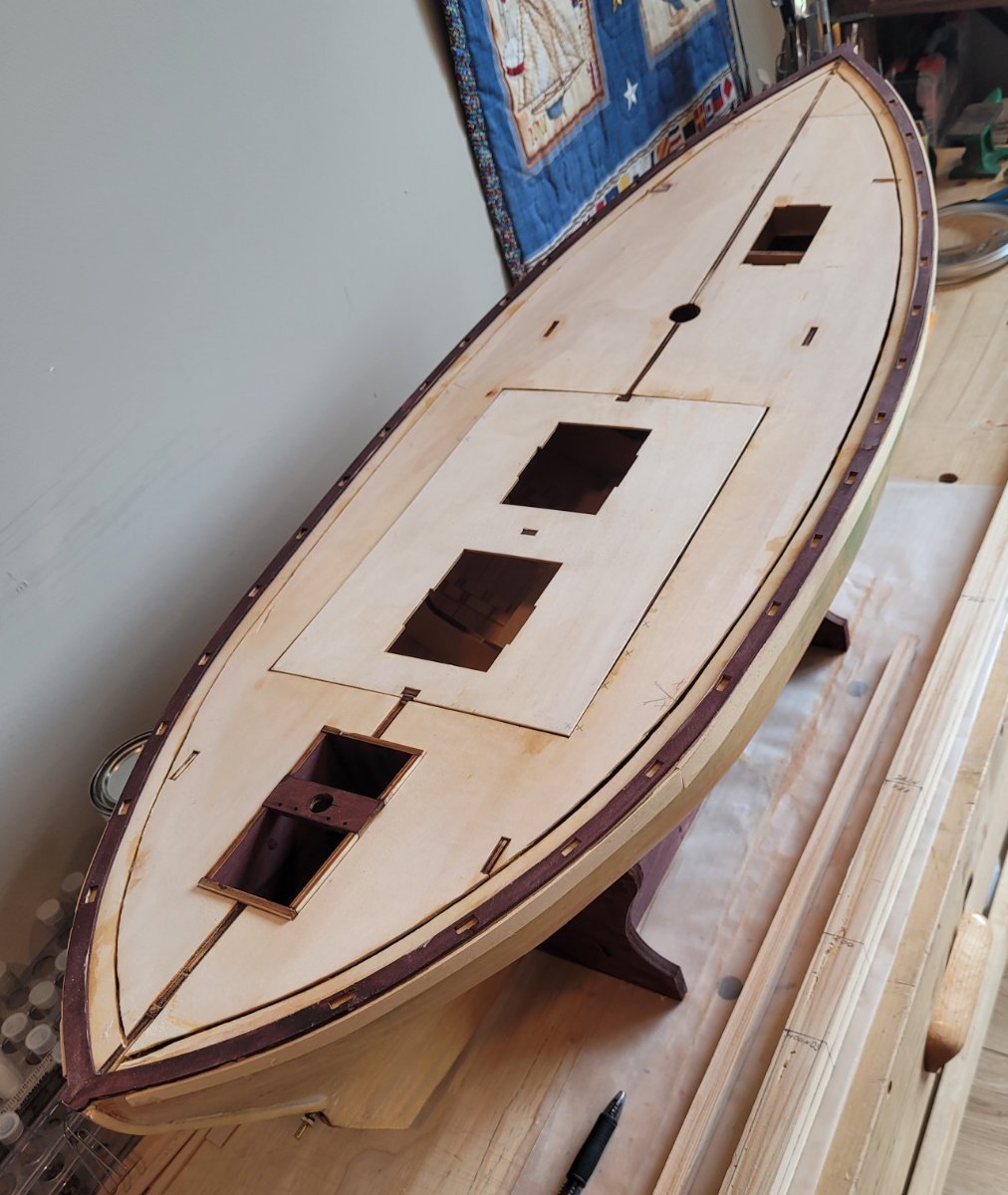
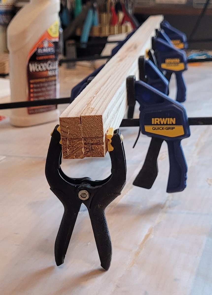
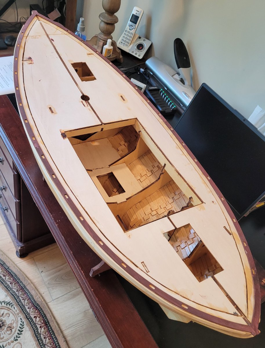
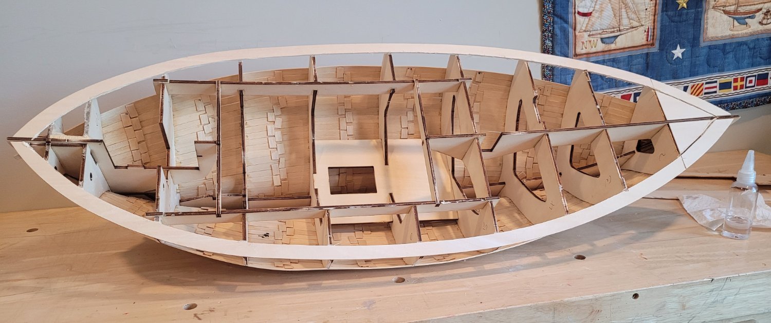
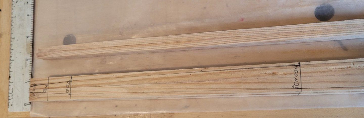
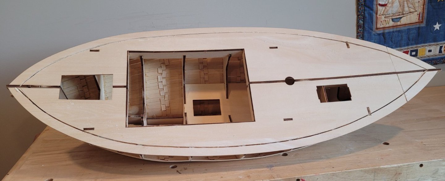
I was a little ahead of myself when I said the hull was ready for deck planking. I still needed to fit the cockpit and the 'deck insert' (Pic 1). This thing is removable to be able to get to the RC equipment. It has no actual counterpoint on the real vessel so I have given it the name 'deck insert'. It looks so simple but it took hours of sanding to fit snuggly into the deck opening. Now we are really ready for the deck planking. The cockpit stands proud of the deck so the planking will butt up against it. The deck insert is flush with the deck and the planking runs over it. The planking will be cut around the deck insert so that it can still be removed. On to a different topic - making the spars. I have made all my spars for at least 30 years from 4 pieces of spruce (from Lumberyard for Model Shipwrights). These are glued up to ensure straightness and no twisting (Pic 2). I don't think many do this and there is probably no really good reason for doing it but it makes me feel good. The four pieces of lumber can be seen here. This is the only thing for which I use Elmer's wood glue (rather than CA) primarily because a lot of glue is used and I want the extra time to make sure the components are flush. The next step involves laying out the taper on one surface (Pic 3). It will be cut with a small bandsaw. A note of possible interest regarding the tapering of spars on this Norwegian vessel compared to British vessels (with which I am much more familiar) - The British spars are a little more tapered. The diameter at the hounds divided by the diameter at the deck for Colin Archer is 83% and for a mast on a British vessel that ratio would have been about 75%. Visually, the spars on Colin Archer are a little fuller than I am accustomed to. I was concerned with the authenticity of the taper given in the kit's plans (they seemed too full). So Jeppe Juul Nielsen made some measurements on his RS 14 Stavenger (one of Colin Archer's other Rescue Ships). I'm using his measurements which are a little slimmer than the kit's. The adjacent spar is the bowsprit.


- 56 replies
-
- 4
-
-
- Colin Archer
- Radio
- (and 1 more)
-
The interior is now epoxied, the subdeck has been reglued in place and the mahogany stained covering boards have been glued on around the edge of the deck. She's ready for the deck planking! It's not much progress but I'm going away for a long weekend and figured I'd get uptodate.

- 56 replies
-
- 1
-

-
- Colin Archer
- Radio
- (and 1 more)
-
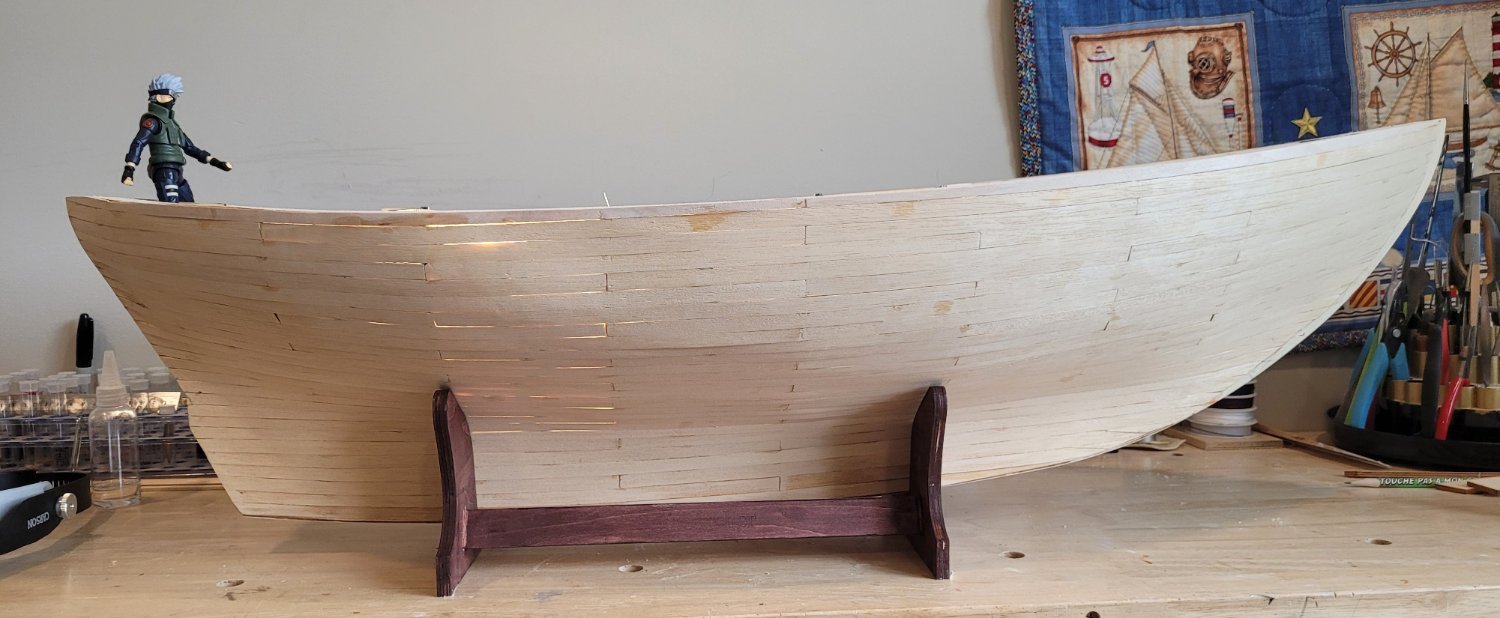
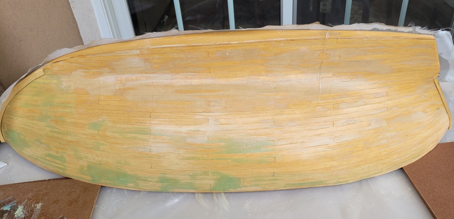
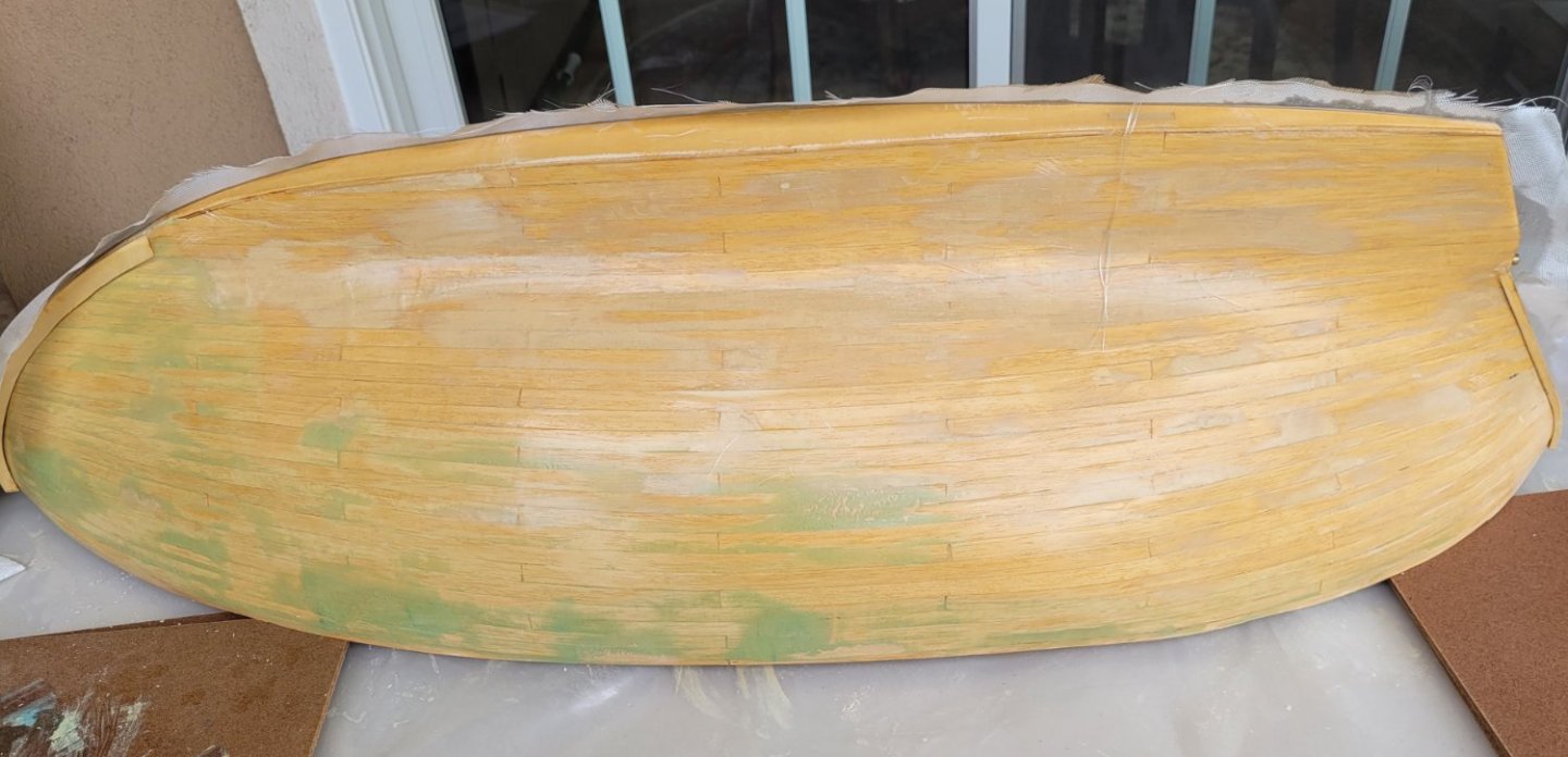
I've finally gotten to the fiberglass. I've been putting it off because its been 10 years since I fiberglassed the 22' Little Leon and I just kept reading articles until I finally felt comfortable moving ahead. The first pic shows the planking sanded roughly to show where filler was needed. The figure is a scale super hero that will be turned into a seaman. You can see light between planks (bright light inside the hull) where my carpenter skills are shown off brilliantly. The hull is ready for fairing/filling. First I used auto filler (2 part, green) and I was not successful. Too stiff and I had to mix such small batches because it set up so quickly. Then I tried a Plastic Wood product in a tube and it wasn't creamy enuff. A different PW product in a little plastic box was perfect. The second pic shows sanded filler with a coat of epoxy resin applied. The green auto filler is clear. I applied the first coat of resin without fiberglass because the planking material seemed porous and I wanted to make sure that it didn't absorb the resin from the cloth and weaken the bond with the wood. The third pic shows the fiberglass applied. The resin coat on the fiber glass is quite thick because I used a brush to apply the resin and to work out entrapped air. I would have used a little squeegee (which also would have removed excess resin) but for the hollow curve between the the keel and the break of the bilge. On Little Leon, I had trouble with the concave curves because the squeegee action kept pulling the fiberglass away from the wood. The thick layer caused some drips but I just cut and sanded them off. I'm planning to thin the resin with 5% laquear thinner for the final 1 or 2 coats to avoid drips. I may only need 1 since there is very little exposed weave because of the thick layer of resin.

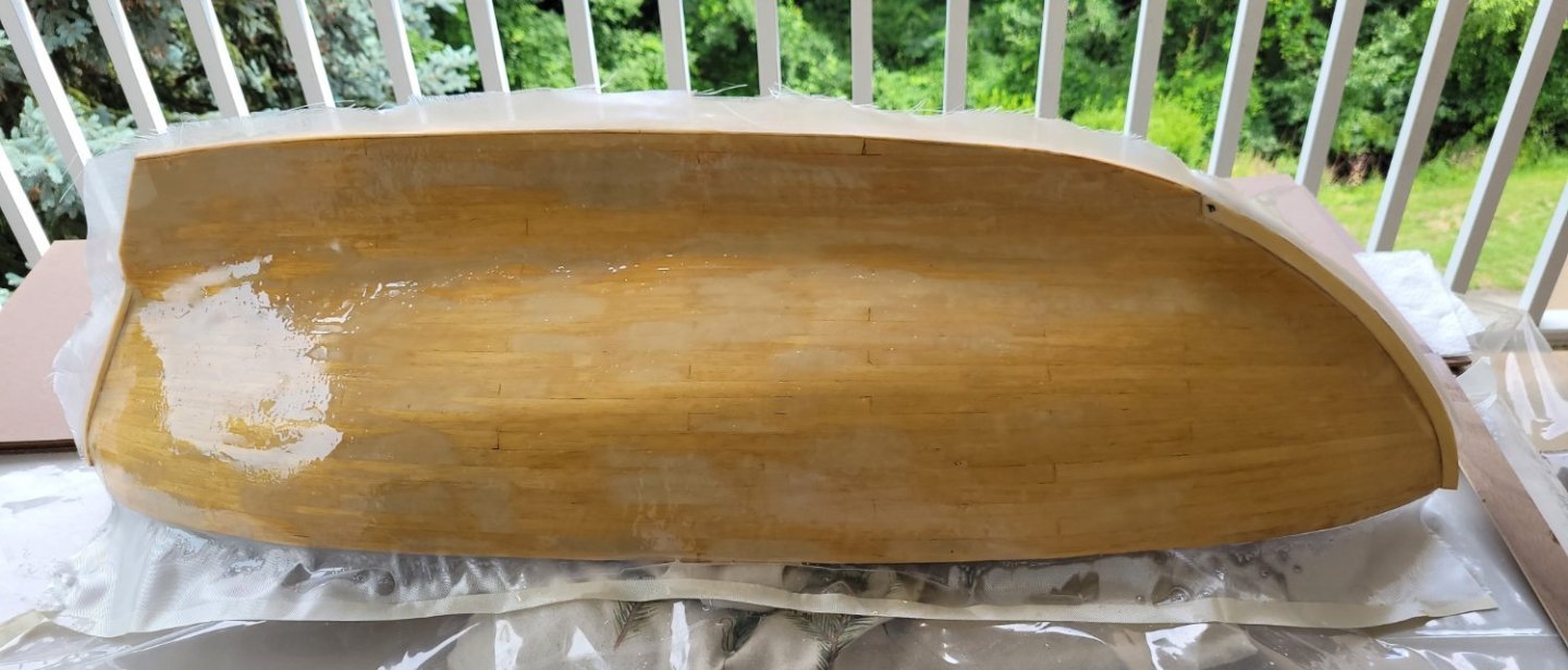
- 56 replies
-
- 2
-
-
- Colin Archer
- Radio
- (and 1 more)
-
Ian, Great info, thanks. I didn't even notice that the 785HB spec sheet gave info at two voltages (4.8 and 6.0). I'm guessing when I get the Williams book he will explain what the multiple voltages are all about. By the way I'm using 2oz fiberglass cloth. She has a total of 777 sqin of sail but it is broken up into 3 sails for control purpose. Mainsail/topsail is 374 sqin, the staysail is 139 sqin and the jib is 202 sq in. The remaining 62 sqin is the mizzen and that just flops around I guess. I think force will vary linearly with area so 374/800 x 20 = 9.4 lbs which means using the 6.0v specs should plenty. I hope my logic is correct. Its probably conservative since the mainsail is only 278 sqin and the topsail is 96 sqin but it I'll but it acts like less as it dumps more wind than the mainsail itself. As far as Little Leon goes she's actually a brigantine since she only has 2 masts. Each of the yards has its own braces but the port braces are all led into a single line as are the port braces. These single lines are looped together. This puts the braces on a sort of loop with no ends to get tangled. There are no halyards. The sheets and clewlines are separate for each yard but for one yard they are also looped. The jib sheets are also looped port to starboard as well as the staysail sheets. The end result is that only the main sheet is a line with an end. Thanks again, Doug
-
Thanks R, I've ordered the book from Amazon and printed the "sail winches which type" article for reading! Thanks again, Doug
-
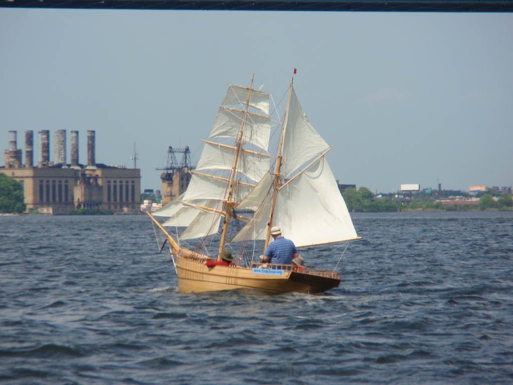
Ian, Please understand that I know NOTHING about RC and I've never sailed an RC sailboat or any other RC thing except maybe a car. I'm a pretty good sailor though. I'm attaching a photo of a boat I built, Leon, that, like RS1 Colin Archer, was designed and built by Colin Archer!) I'm learning about RC from where ever and whoever I can. The first thing I learned is that winch servos are somewhat rare as they are either mostly or only used in large sailboats. I looked at HiTec and they have a winch servo, HS-785HB, that precisely matches the dimensions of the 3 sail winches in diagrams for RS1 Colin Archer that they provide even though they provide no support for RC application! Since you mentioned 20lbs pull, I calc'd 7.5lbs for this servo from specs that 'standing torque' is 122 oz.in (what is standing torque?). The radius of the winch is 1" so that gives 7.6 lbs pull. Am I understanding the specs correctly? If I remember correctly this is about $60. Another winch servo that surfaced was from Tower - they said "Our SPMSS7110 is designed to be a winch for crawlers." Ian, do you know what a crawler is? They had several 'lifting torque' figures ranging from 130 to 180 oz (they seemed to assume the 'in' part of the unit) at different voltages. Also if I remember correctly this was about $140. This one seems to be about 2/3 the size of the first one. Ian, any and all comments that you make will be tremendously appreciated! Thanks Doug
- 56 replies
-
- 1
-
-
- Colin Archer
- Radio
- (and 1 more)
-
Definitely R. Partly for waterproofing and partly for strength as the planking material is quite thin [2mm (5/64")] for the 11cm (4.3") spacing of the bulkheads. Then on the inside I'll be using Epoxy resin for waterproofing. My wife wants me to leave some of the planking visible (i.e. unpainted) which would be the underwater portion - I haven't decided yet (it'll depend on appearance when sailing). Just one mini strake left before sanding and fiberglassing. I ran out of planking material with the little space remaining. In fact, the very last plank was created by scarfing two little pieces together. My local hardware store had 1 piece of 1/16" bass wood (3" wide and 24" long) which I'll use to fill that space. I'll use a piece about 1/4" wide and then sand it down flush with the subdeck.
-
About 5 strakes on each side still need to be applied. This post focuses on how to waterproof the inside of the hull. I finally decided to remove the deck so that I can brush on epoxy resin. Then I can reattach the deck. A Dremel Saw-Max, borrowed from my friend Marty, was perfect for the job. I made the cut 3/4" in from the edge of the deck (photo left). Removing the deck was not too difficult because the wood to wood contact between the top of the bulkheads and the deck was poor so the glue joint gave pretty easily (photo right). When I finish planking I will fiber glass the outside and then brush the inside and the bottom of the deck and then reassemble.

- 56 replies
-
- 2
-
-
- Colin Archer
- Radio
- (and 1 more)
-
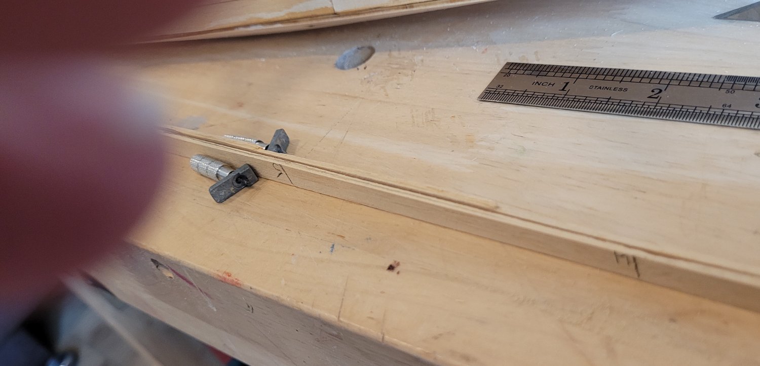
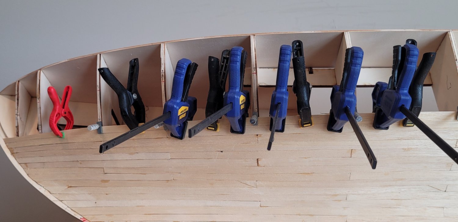
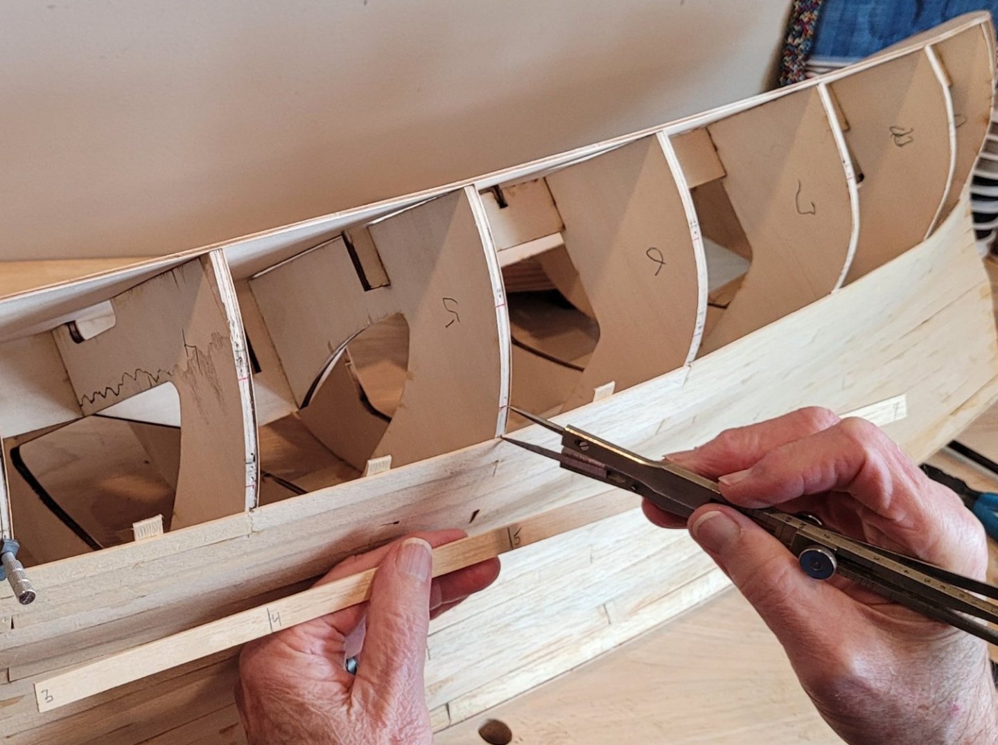
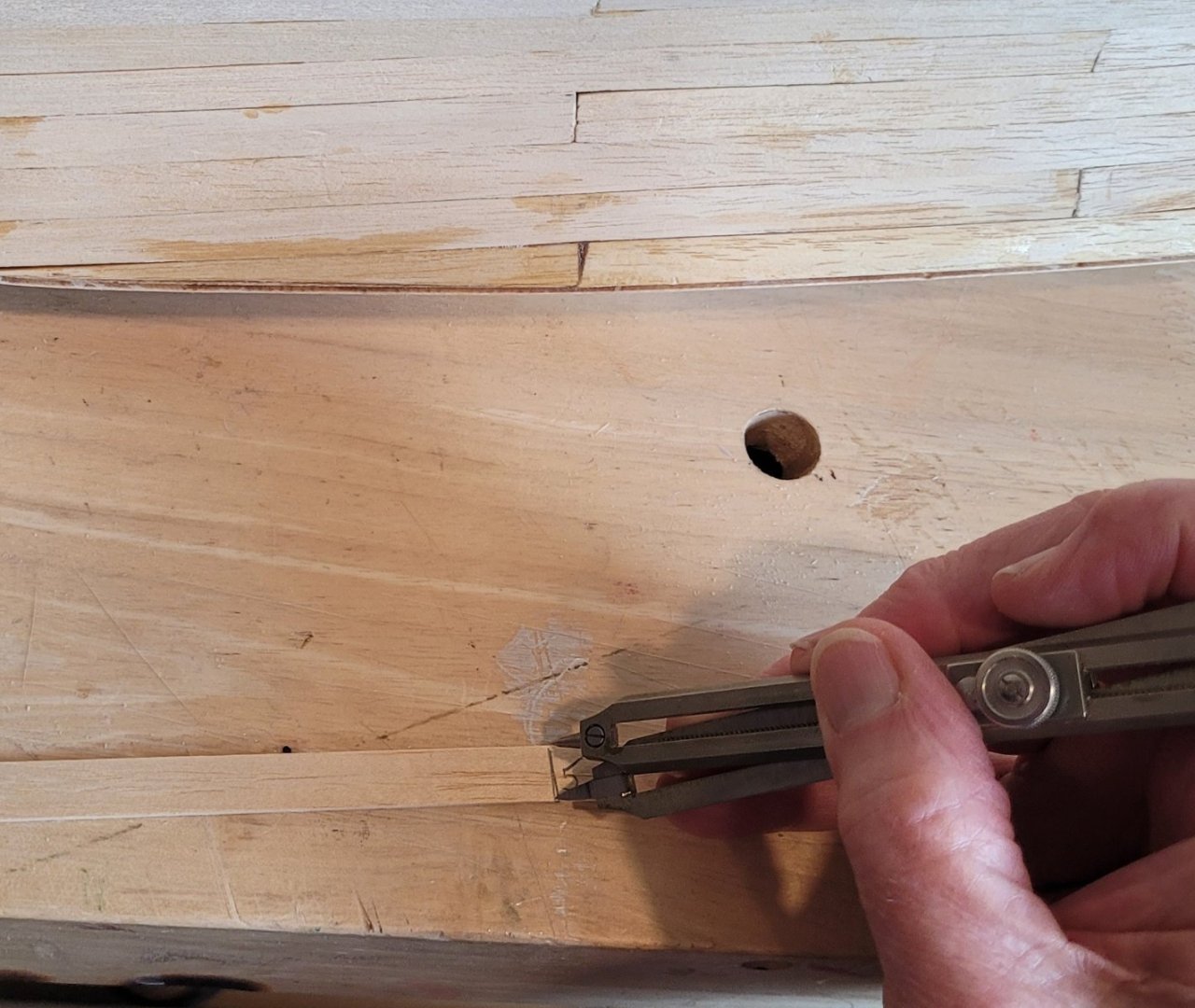
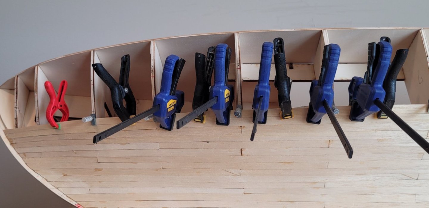
I was going to wait until the planking was finished but I'm going slower than expected what with a trip to Eastern Europe and completing a model of the clipper Thermopylea for a friend. So I figured I'd make a posting now that she is 2/3rds planked to show some more details of Underhill's method. With the red mark showing where the battens were, the proportional dividers are used to pick off the distance from the top of the last plank to the next red mark. We have set the dividers to 3 to 2 because the bulkhead with the largest distance to the next red mark is 15mm and the width of each plank is 10mm (1st picture). The other end of the dividers is used to mark the plank width (2nd picture). The divider marks are connected by a pencil line and a knife used to reduce the strip to the proper width for the plank. The plank on the other side is marked to match the first one, cut and sanded to be exactly the same as the first one (3rd picture). In the right side of the photo the 2nd plank has been sanded to be the same width as the original plank but on the left side, the 2nd plank has only been rough cut and still needs to be sanded down. In the 4th picture the plank is glued and clamped. The silver model shipway's plank clamps fasten the plank to the bulkheads. The black spring clamps (and the little red one too) hold the plank against the tabs that were glued to the previous plank. Lastly the blue mini bar clamps hold the new plank in line with the previous plank. Fortunately, when the glue dries the plank stays aligned with the original plank. The last photo shows the tabs for all the completed planks. Not pretty, but they work.


- 56 replies
-
- 4
-
-
- Colin Archer
- Radio
- (and 1 more)
-
Mr Sundt, I am building Billings' Colin Archer RS1 in wood for RC. I have never done RC for anything. Can you tell me what RC components you used since Billings says where to put them but not what they are and I have no idea how to size them. The articles I've seen seem to assume that I know something about RC (which I don't). Thanks for any help Doug McKenzie PS I built a scratch model of Leon which is now in the museum at Tollerodden Foundation in Larvik. That might be near you I have no idea since I'm from New Jersey, USA.
-
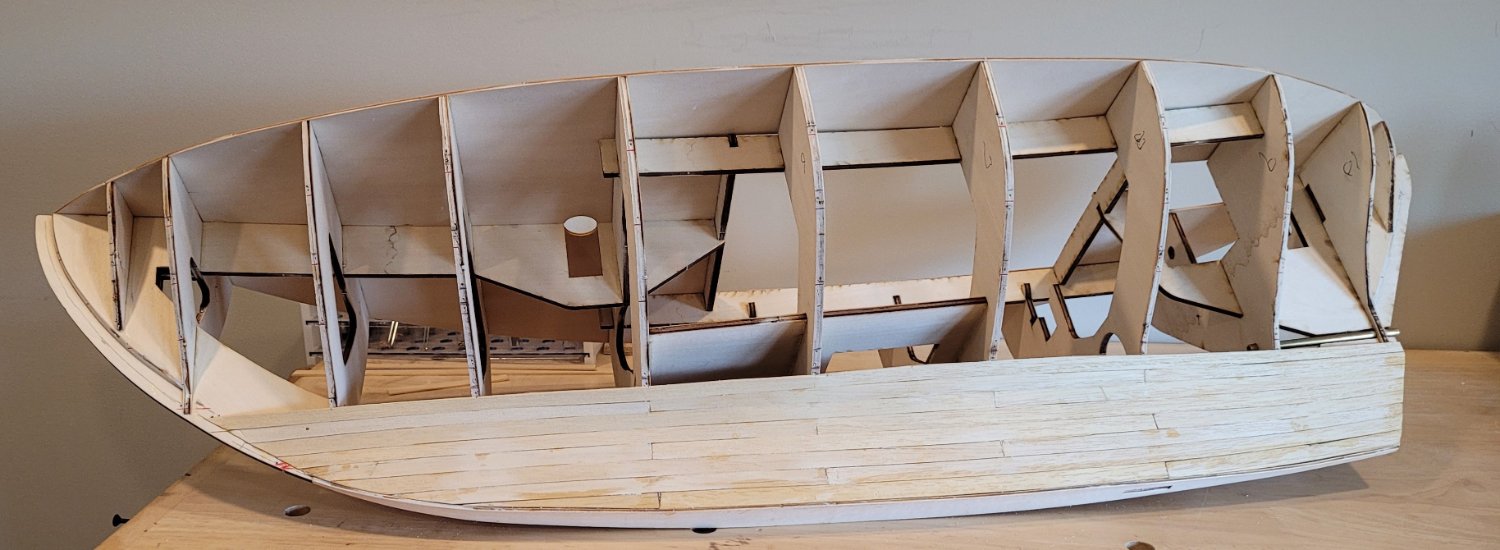
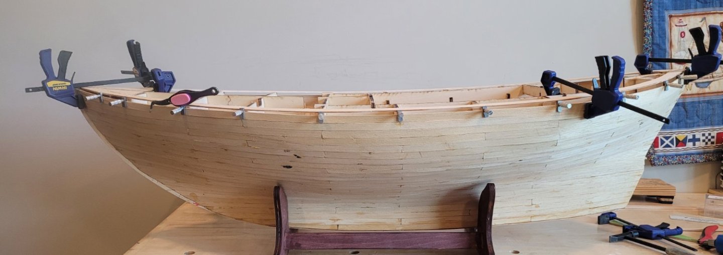
8 of 27 strakes are now in place. The only reason I include this photo is because I forgot to mention that the garboard strake on this hull is not like on big ships. The reverse curvature, midship, on this yacht hull means the garboard strake has very little twist and very little width variation. At the 8th strake, however, the midship bulkheads flare out toward the full beam and the bow and stern remain vertical. This means the 8th strake has a lot of twist and more variation in width than the previous planks. A curiosity for me as I've never planked a yacht hull before as I've said.

-
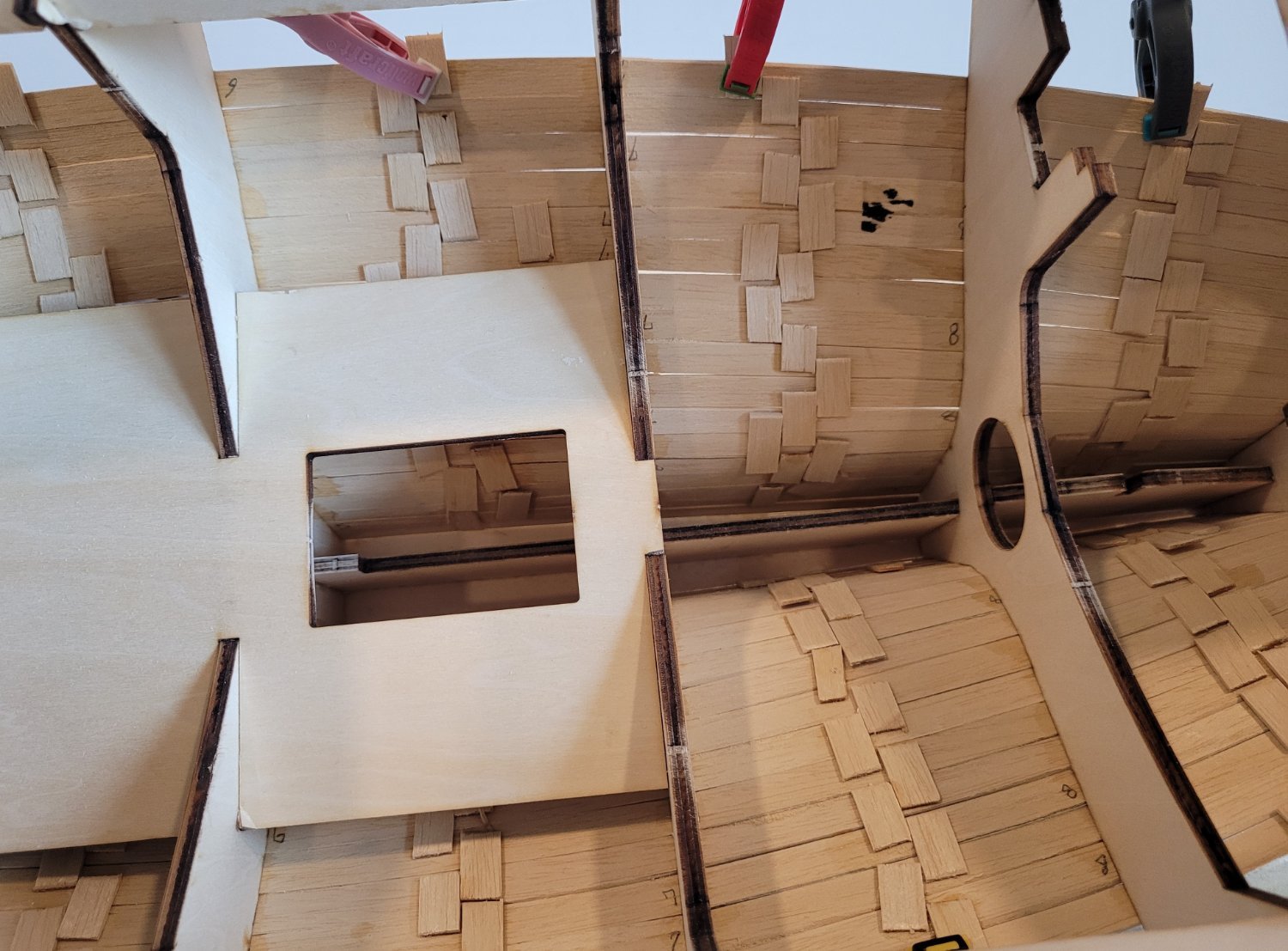
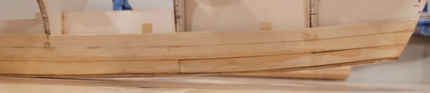
After putting on the garboard strake and 2 strakes above it, it seemed like a good time for a posting because there were two unexpected challenges that emerged which I wanted to describe. First, though, the expected results, i.e. at the stern. All three strakes were handled using Underhill's method of first determining how many strakes would fall in the space between the keel and the lowest batten (that has now been replaced by red marks on the edges of the bulkheads). 4.2 strakes will fit nicely because the widest spaces (midship) between the keel and the lowest batten are 4.2 cm and the planks are all taken from 1 cm wide stock. As the stern is approached, the spaces generally get slightly smaller and the width of the planks are reduced proportionately. This is expected. Now we move to the bow. The keel is not straight as it is on large ships, rather it curves upwards from a little forward of midship and keeps curving up till it intersects the deck line. This effects the Underhill method in a big way because as soon as that upcurve begins, the distance between the keel and the 1st batten becomes less useful. If we took that distance literally we would be tapering all the planks so sharply that it would look ridiculous. I introduced the idea of a pseudo-keel that results from extrapolating the distances of the keel from the 1st batten from all of the after bulkheads up to but not including the first bulkhead where the keel starts to seriously curve up. Then I used Underhill's method between the pseudo-keel and the 1st batten to determine the width of a pseudo-plank. This normal looking plank was then laid in place extending forward of the upward curving real keel. The pseudo-plank was then cut to lie against the real upcurving keel, resulting in the real plank. This produces a plank that comes to a sharp point (probably unrealistic) but I couldn't figure anyway around it. It's not like I was going to create a 'jogged margin keel'. As you may have guessed by now, I have no idea how a hull shape like this was actually planked - none of the pictures from the Emma replica showed this. If anyone knows, I'd love to learn. So that was the first unexpected situation. The second arose because the planking material is pretty thin (2 mm / 5/64") relative to the spacing of the bulkheads (11 cm / 4.3"). This meant that adjacent planks did not meet flush along their edges. I considered trying to glue the edges together but with the extra glue and the additional need to clamp the adjacent planks to keep them flush would have been really messy. Instead I used short pieces of the planking material between the bulkheads (seen in both pictures above). First, I glued and clamped them to an already installed plank. Then I glued the new plank to them and clamped them while gluing and clamping the new plank to all the bulkheads. This should keep the final sanding, when the planking is done, to a reasonable level minimizing the number of very thin hull spots. Next I'll just keep planking hoping that any additional unexpected situations yield to simple solutions!

- 56 replies
-
- 3
-
-
- Colin Archer
- Radio
- (and 1 more)
-
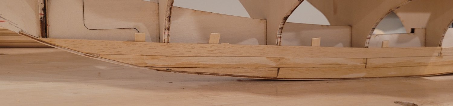
I think I'm nearly done with the planking battens. It was more work than I expected and one interesting result is that I don't believe that I will need any stealer planks in the stern. Not sure about this but we'll see - It's never happened before to me - it's probably due to the lack of any transom . I did a few things differently from Underhill. One is that I put battens on both sides from the very beginning - it just seems to make judging the curves a little easier. I also used balsa wood strips while he used sycamore - he was smart, I less so. The balsa strips broke too often when I adjusted the batten positions over and over again. In any event I'll leave the boat a day or so and decide if I need to make any more adjustments. I'm pleased that I was able to follow the photos of the Emma replica reasonably well. I'll know for sure when the planking is done. The bow view is below, followed by the stern view and the side view. I believe Underhill planked with the battens in place, I don't do this. I mark the edge of the bulkheads where the battens cross them with a red ballpoint line to distinguish it from all the pencil lines that have been marked during the adjustments of the battens. Then I can remove the brads and the battens so that they are not in the way. That won't make a very interesting photo so the next posting will have a few strakes in place. The kit supplies 6" stock for the planks. From the photos I estimate that the replica uses 7-8" lumber. Close enuff for engineering work. The strips are about 35" long and the length on deck is about 36". I'm going to be using probably 3 or 4 planks per strake so they will be around 11' to 15' full scale - a bit long but short enough to avoid having to use much set to follow the batten pattern.
- 56 replies
-
- 5
-
-
- Colin Archer
- Radio
- (and 1 more)
-
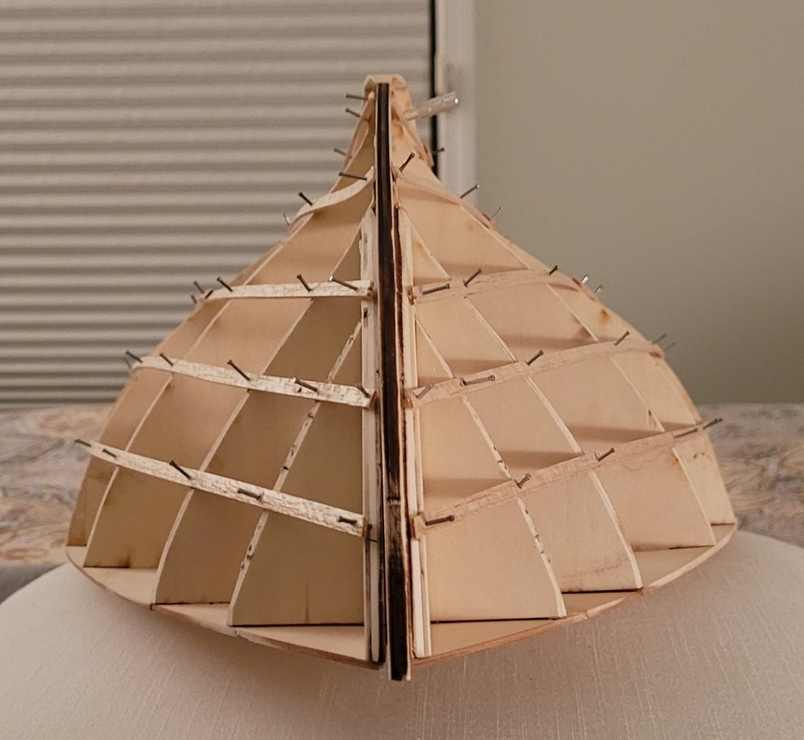
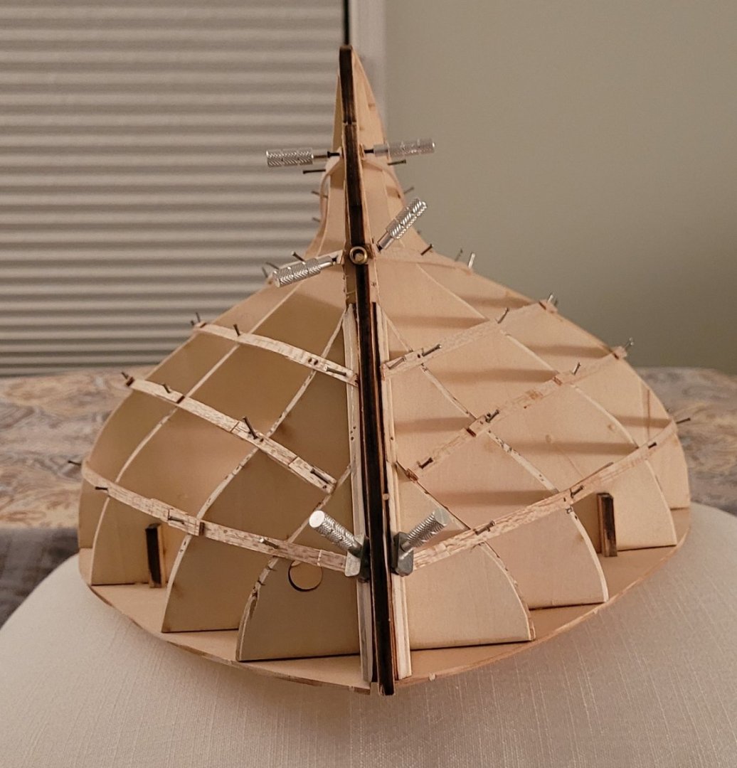
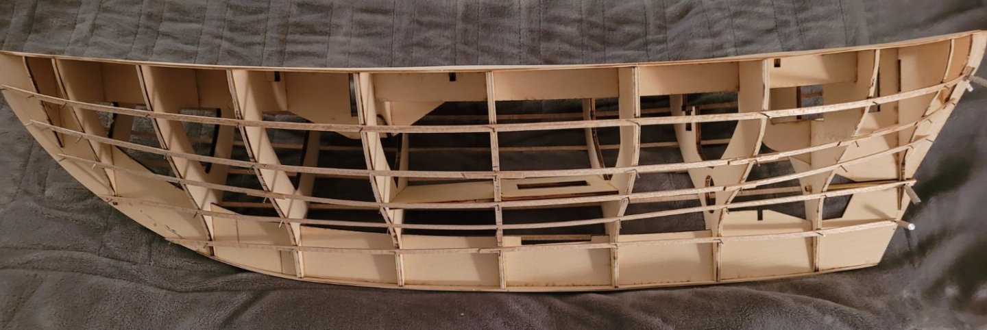
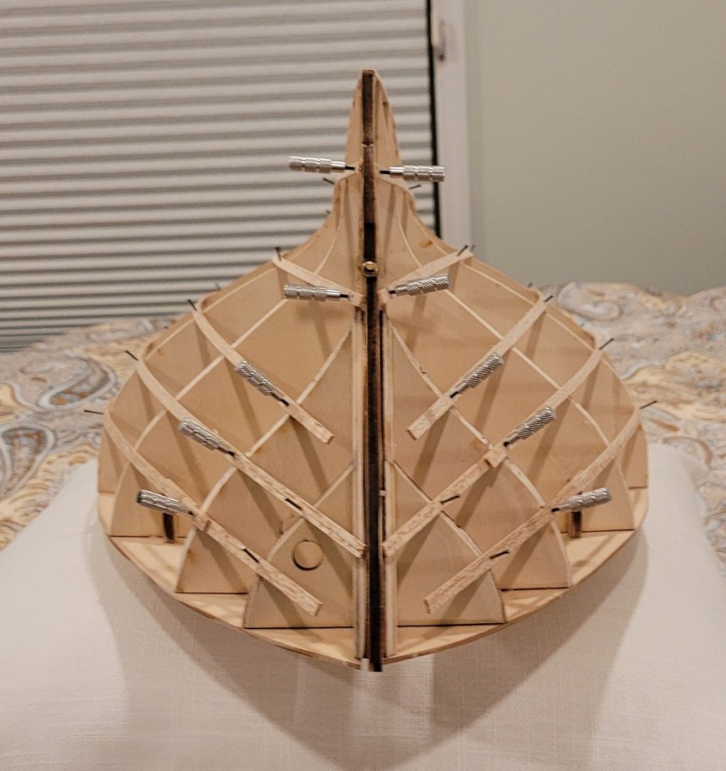
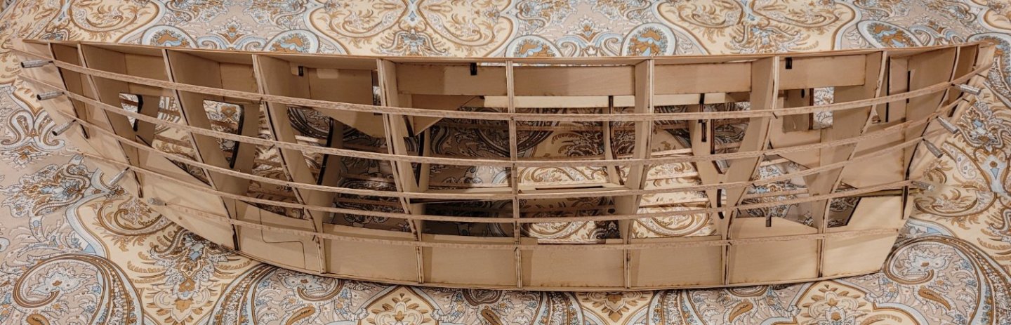
I was going to wait until I was completely satisfied with the batten positions before I made another post but, after the first set of adjustments, the difference was so striking that I figured that anyone not familiar with Underhill's method might be interested in seeing the progression as the battens are adjusted. The photos below show the results of the first adjustment. The adjusted battens at the bow are shown here: And at the stern: I probably should explain why I am going to all this trouble since this will be a working RC model, fiberglassed and painted and the planking won't be visible. The answer is that I love planking a hull with Underhill's method and this particular vessel has a unusual hull form for me. I have never worked with a double ender before and the 'S' shaped bulkheads in the midbody is new to me. The 'S' shape is, of course, common in sailing yachts but I've never built a model of one of those. Also the sheer curve is much less pronounced than what I am familiar with. And the photos of the construction of the replica, Emma, that I mentioned before, show 2 features of interest: 1-- The run of the strakes is unusually straight (i.e. horizontal), to my eye, which is partially due to the light sheer curve and 2-- The uniformity of plank width at the bow and stern (i.e. the small amount of taper) is new to me. Unfortunately, I can't figure out how to display these photos of the replica here. Nonetheless, I am trying to reflect these unusual features when adjusting the battens. The beam shot below attempts to show the movement of the battens towards producing the straight , horizontal strakes and the relatively uniform width of, particularly, the topside strakes. Clearly, more adjustment is needed. I don't know when I'll make the next posting - I guess it depends on how large the adjustments that I make are.
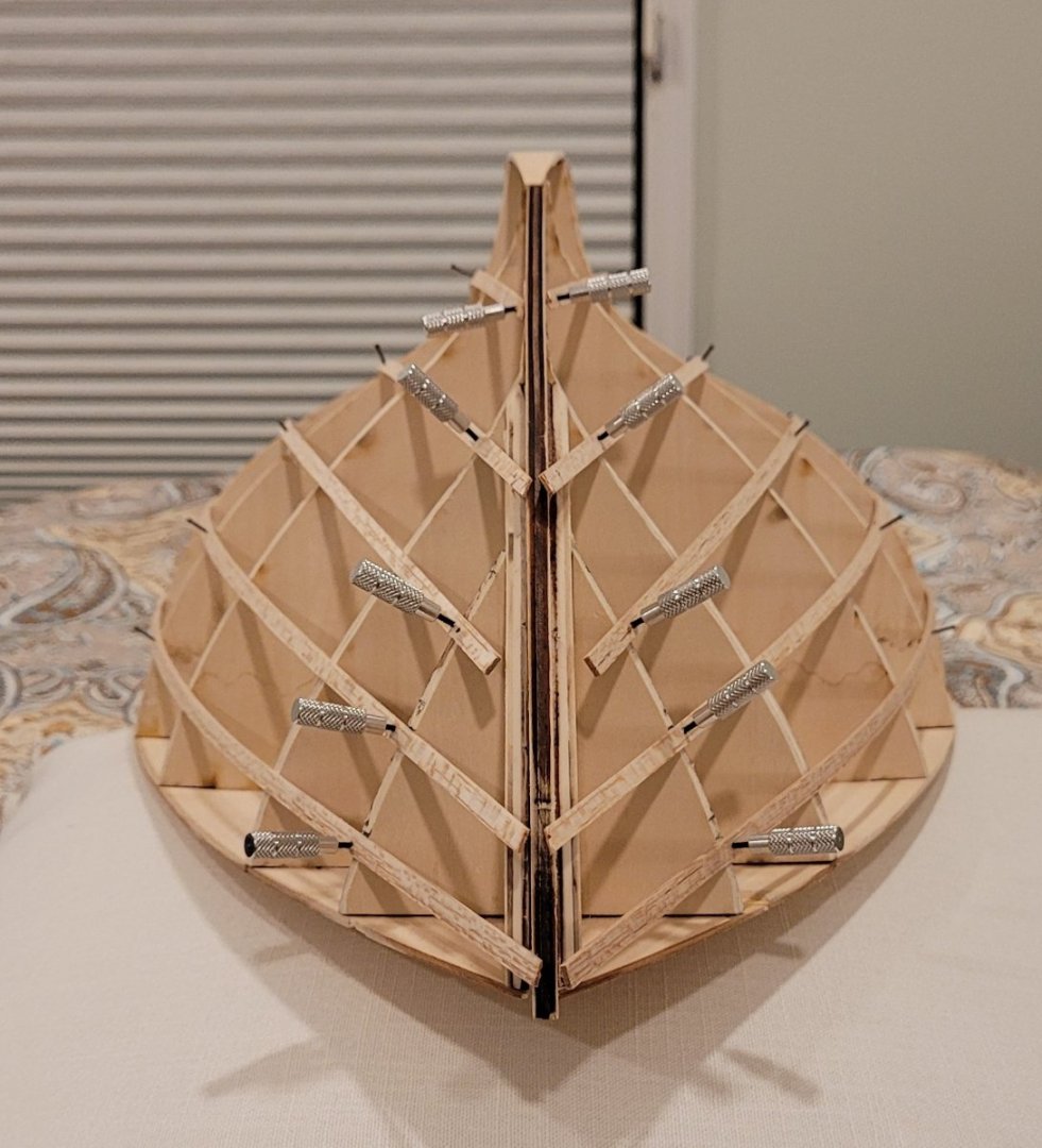
- 56 replies
-
- 4
-
-
- Colin Archer
- Radio
- (and 1 more)