HOLIDAY DONATION DRIVE - SUPPORT MSW - DO YOUR PART TO KEEP THIS GREAT FORUM GOING! (89 donations so far out of 49,000 members - C'mon guys!)
×


Doug McKenzie
-
Posts
221 -
Joined
-
Last visited
Content Type
Profiles
Forums
Gallery
Events
Everything posted by Doug McKenzie
-
Thanks very much Chris
-
Chuck, a fellow suggested that I add 'Radio' to my Colin Archer title. I can't figure out how to edit the title. Is there a way? I did add 'Radio Control' as a keyword but changing the title does seem like a good idea. Doug
-
Ian, great idea. I guess I just have to edit my log title - I'll see if I can!
- 56 replies
-
- 1
-

-
- Colin Archer
- Radio
- (and 1 more)
-
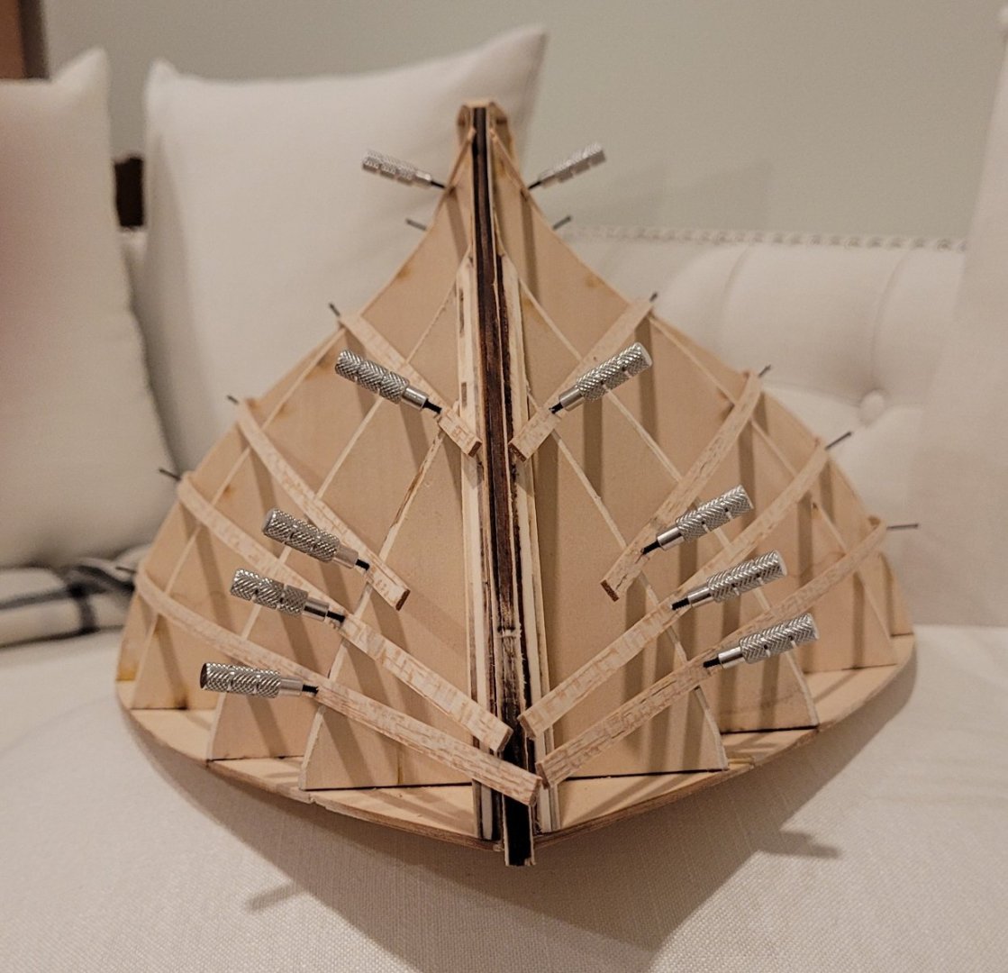
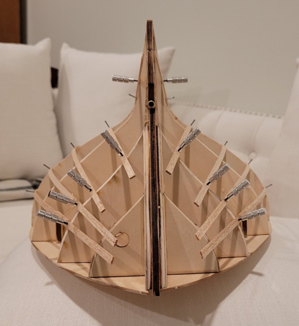
The first pass at the batten positions has been made. The midship bulkhead was divided into 6 roughly equal sections using 5 battens. On one side of the ship, all 5 battens where laid into position by gently pressing the battens against the bulkheads without worrying about the relationship between the battens. In other words, it was attempted to not put any set to the battens. Later we'll use set to make everything look good. At this point we are just getting a sense of how the hull is shaped. So in this first photo of the bow it is clear that the top side planks will need to be considerably wider than the battens indicate and similarly the underwater planks will need to be narrower. The same is true for the stern seen in the picture below. I used 1/16" x 3/16" battens so that the fasteners (5/8" brads and the plank clamp screws) would not split the battens. The bulkhead were 3/16" thick. The two pictures below show the battens from off the bow and off the stern. The batten closest to the keel can be seen clearly in these views while being almost invisible int the bow and stern photos. In the next posting I will move the battens to achieve two objectives: 1-- To make the run of the planks much more attractive and 2-- To try to match some photos of a 2013 replica of another one of Colin Archer's rescue ships, RS 22.

- 56 replies
-
- 5
-
-
- Colin Archer
- Radio
- (and 1 more)
-
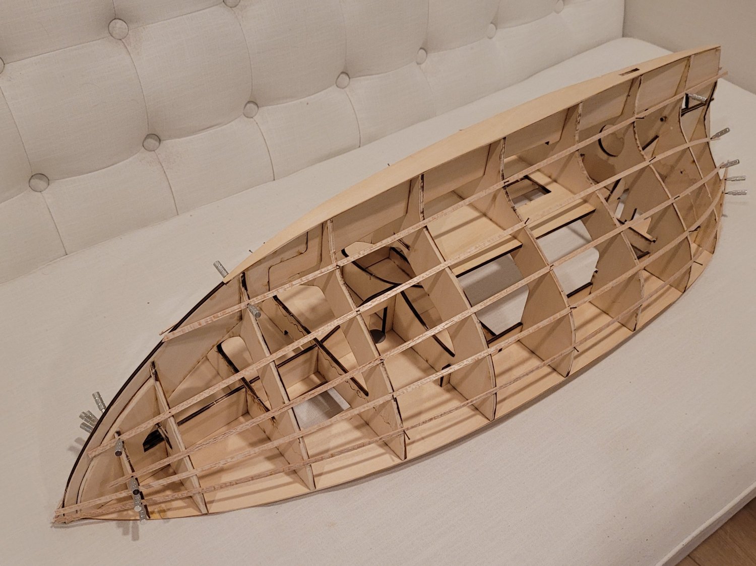
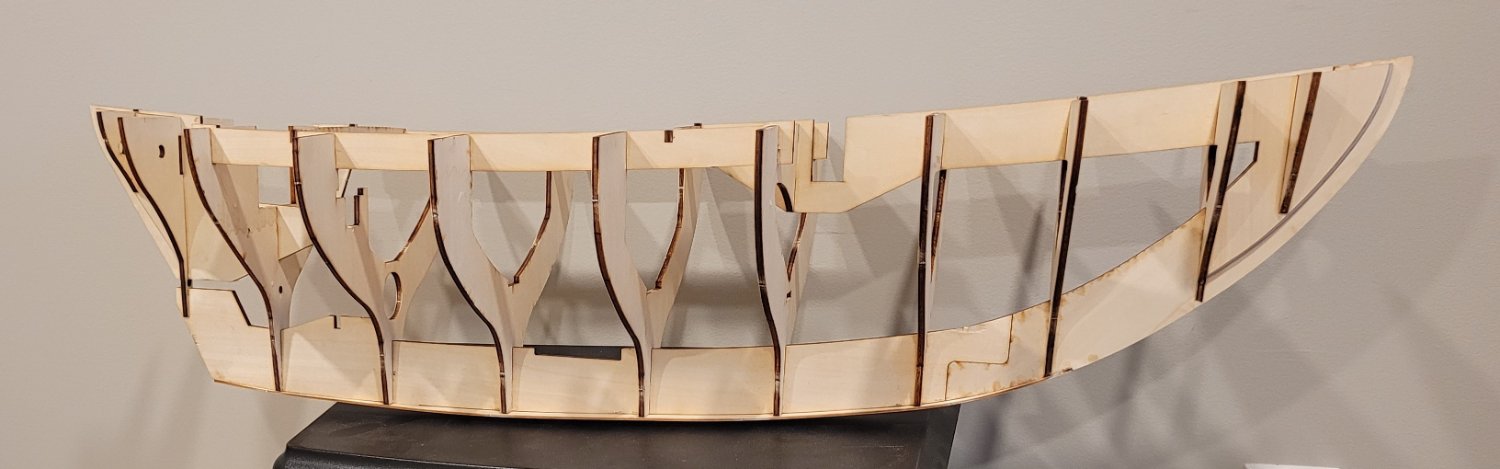
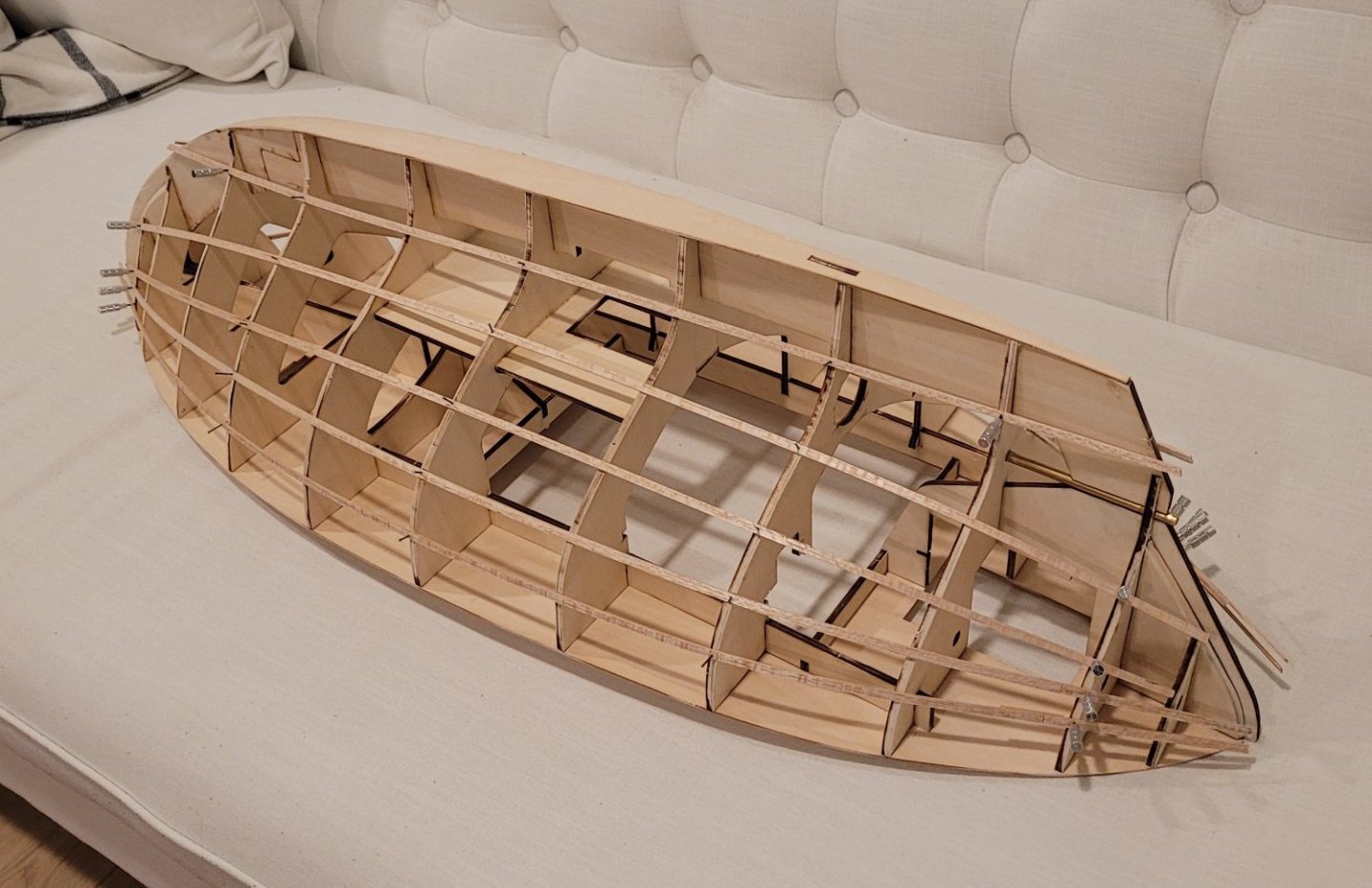
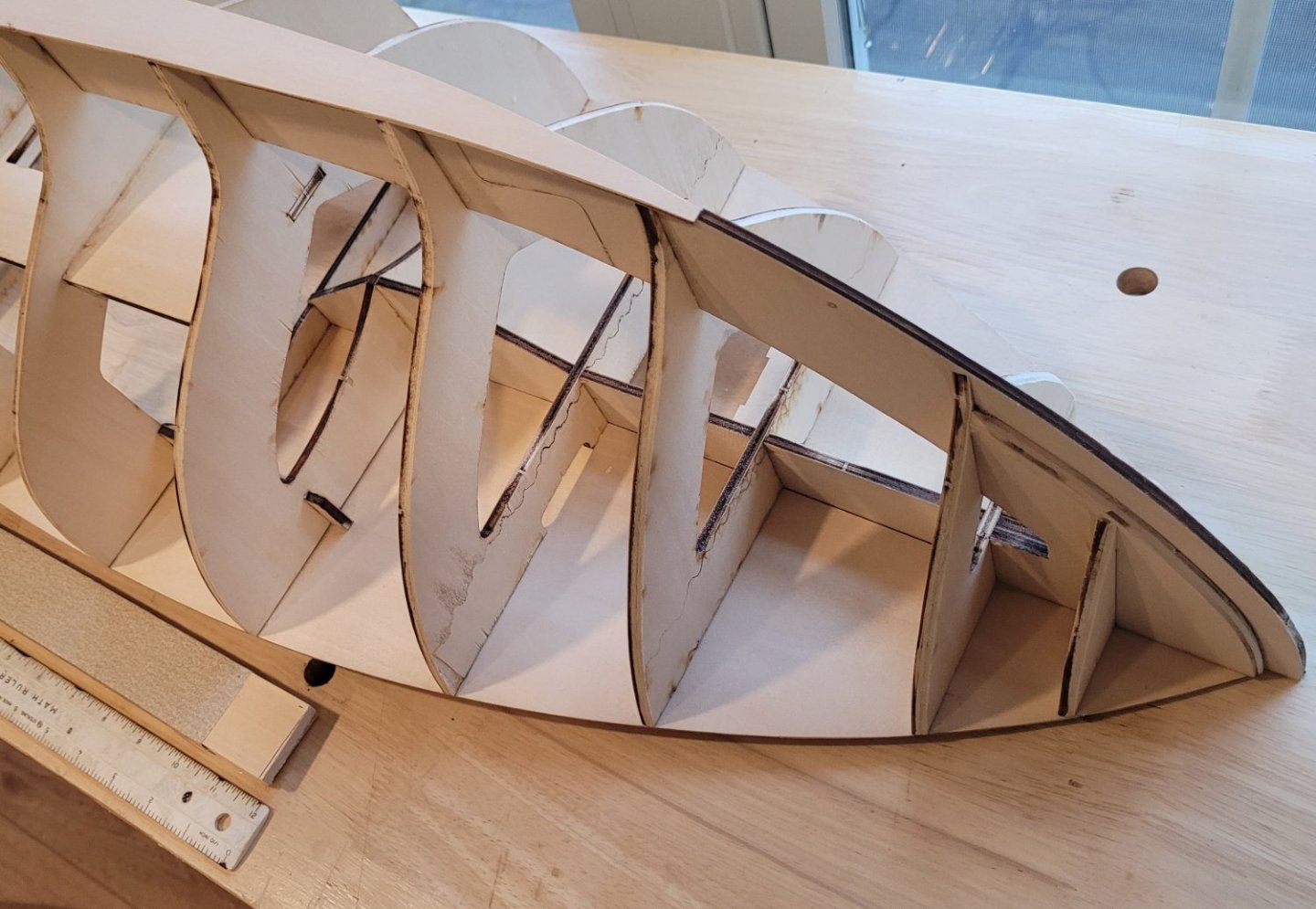
The beveling of the bulkheads for the planking is complete. I don't why exactly, but this task is my very least favorite of all the tasks on a model boat. Sanding a solid hull and thinning the bulwarks of a solid hull is worse for me but I haven't done that for 62 years, so I don't think of it often. In any event, I'm done as shown below. I try to leave a little bit of the laser burn on the midship side of the bulkhead edges to make sure that I don't change the shape of the bulkhead. The furthermost and aftmost bulkheads have a lot more burn left as a result of trying to make sure the bevels on those bulkheads lead to the stem and stern post doublers smoothly. In the next posting, I'll begin Underhill's method of ensuring that the run of all the planking is pleasing.
- 56 replies
-
- 1
-
-
- Colin Archer
- Radio
- (and 1 more)
-
Jeppe Juul Nielsen has written about Colin Archer, the man and his boats. RS1 Colin Archer is included. A PDF is attached that is most interesting. Colin Archer - the designer at Tollerodden 03a.pdf
-
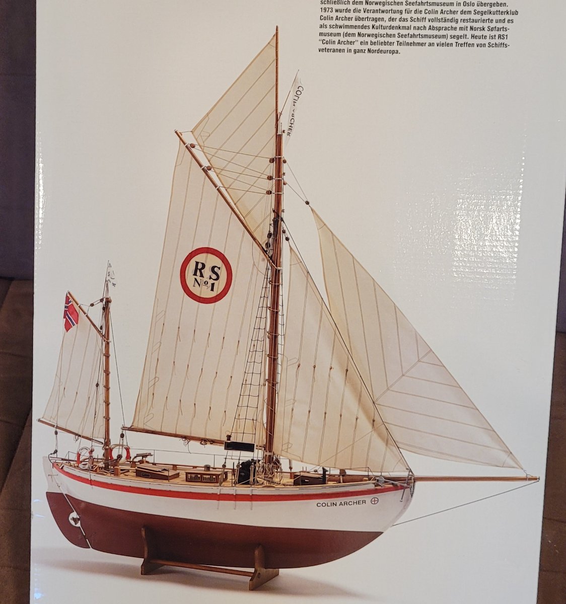
RS1 Colin Archer, named for her designer / builder, was launched in 1893 in Larvik, Norway. The model, 1:15, is being kit built for Radio Control. The kit is by Billing Boats in Denmark. I wanted to build an RC boat and this one has a special appeal because Colin Archer also designed and built Leon, a 302 ton brigantine in 1880. I scratch built a model of Leon at 1:48. She now sits in a museum in Larvik dedicated to Colin Archer. Her build is described in forum "Build logs for subjects built 1851 - 1900". RS1 Colin Archer, after 40 years of very successful rescue operations saving many Norwegian fishermen, is now owned by the Norwegian Maritime Museum in Oslo. She is maintained and sailed at vintage ship gatherings in Northern Europe by the Colin Archer Cutter Club. The kit models her after the rescue years as she did not have an auxiliary engine until after she 'retired'. This picture is from the box top of the kit. On the way to being ready for planking, the hull is 37" long. Sparred she will be 50" long (62.5'), 54" high (67.5') with a 13" beam (16.25').


- 56 replies
-
- 3
-
-
- Colin Archer
- Radio
- (and 1 more)
-
Chris, It's possible that I was a little too quick - the $14 didn't actually buy me a kit, rather an original page out of Model Airways News magazine from 1956 advertising the availability of the kit. Fortunately, the drawing of the boat in the ad showed detail not visible on the box cover painting so it had actual value. Mean while refurbishment proceeds and it's more challenging than I expected.
-
Chris, Thanks a bunch. I can buy an original kit for $14 from eBay which I' m doing because maybe the instructions will give more info like the builder - who knows? In any event thanks again Doug
-
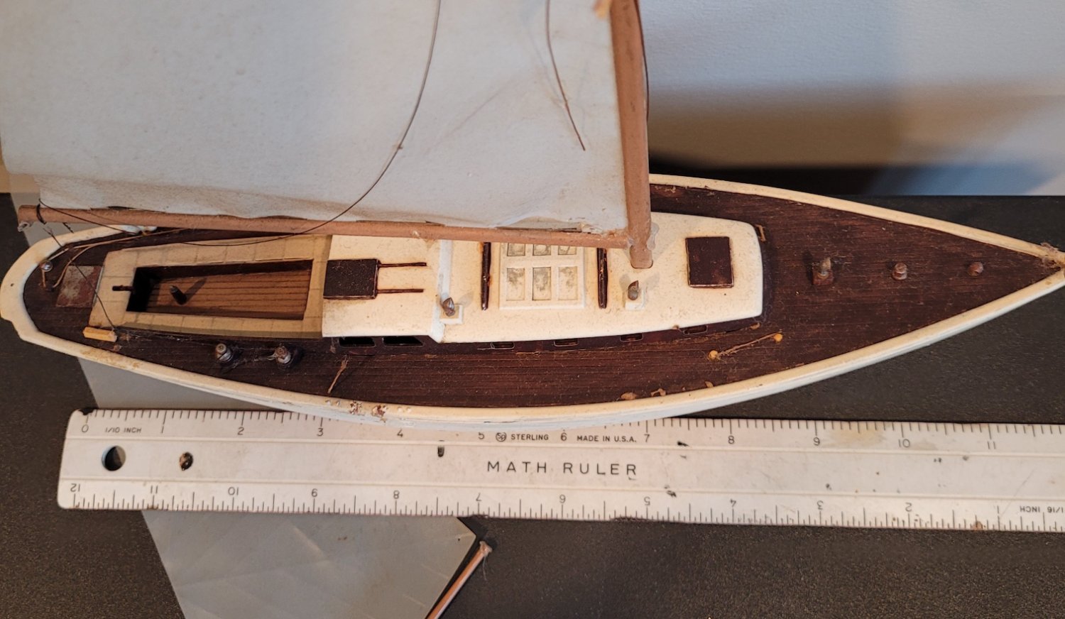
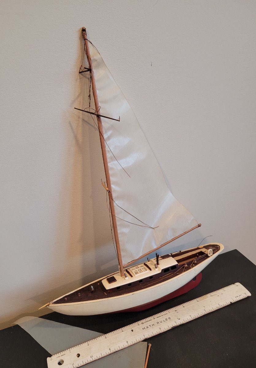
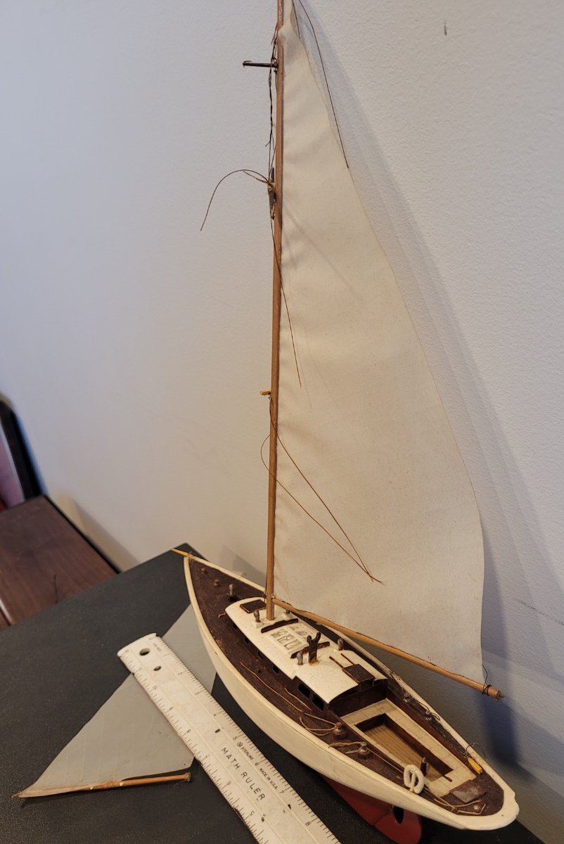
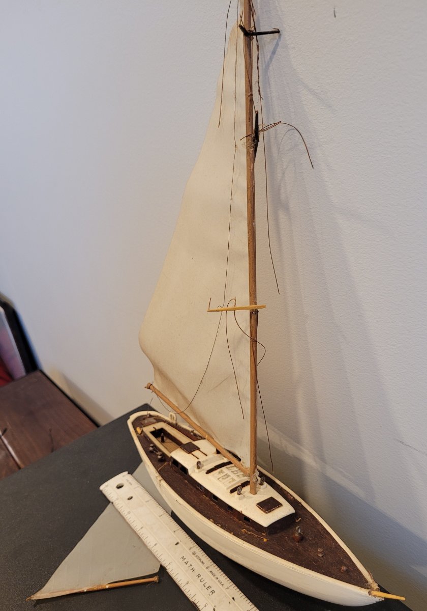
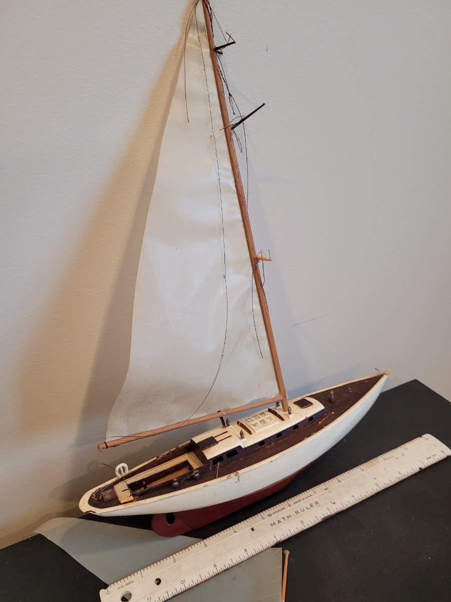
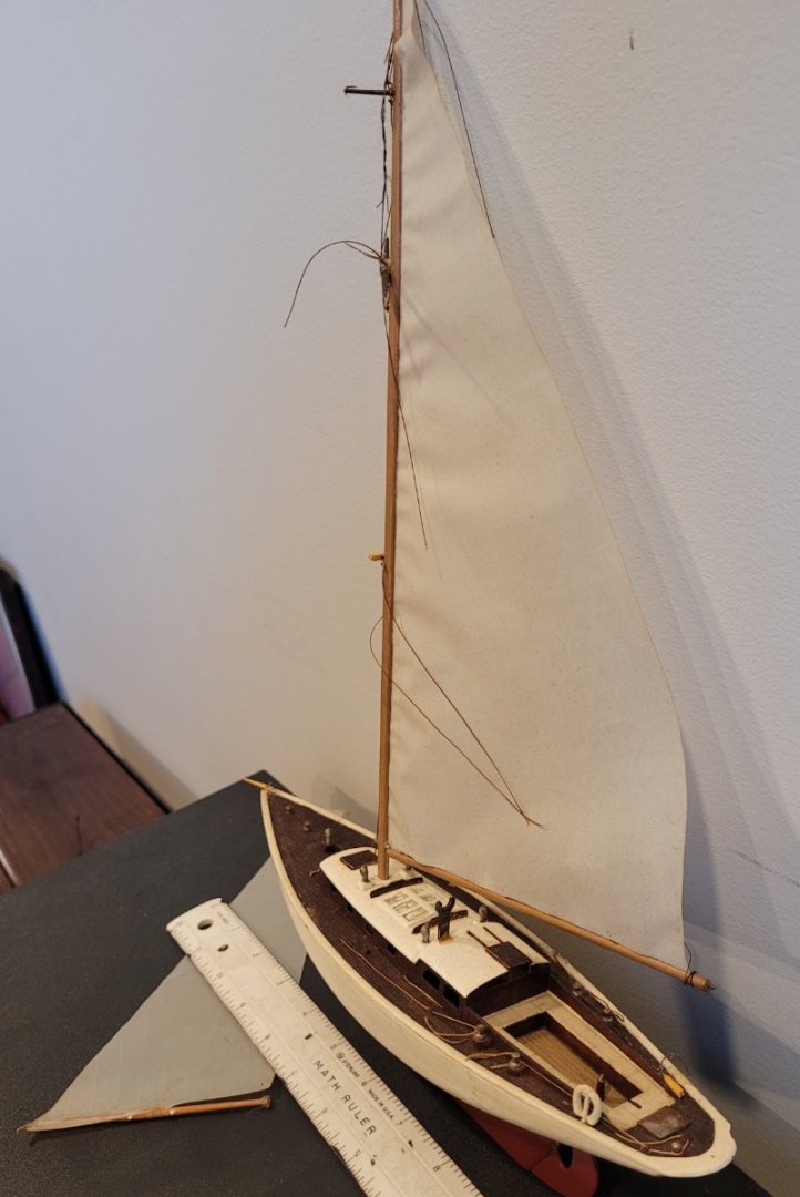
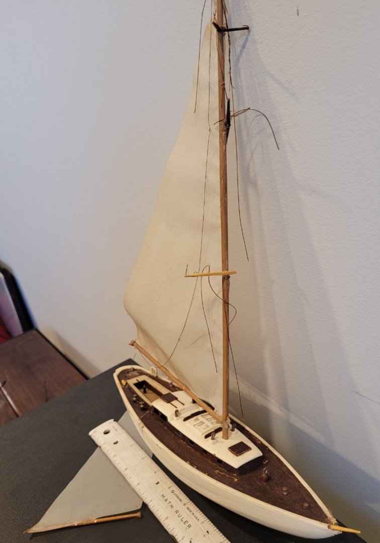
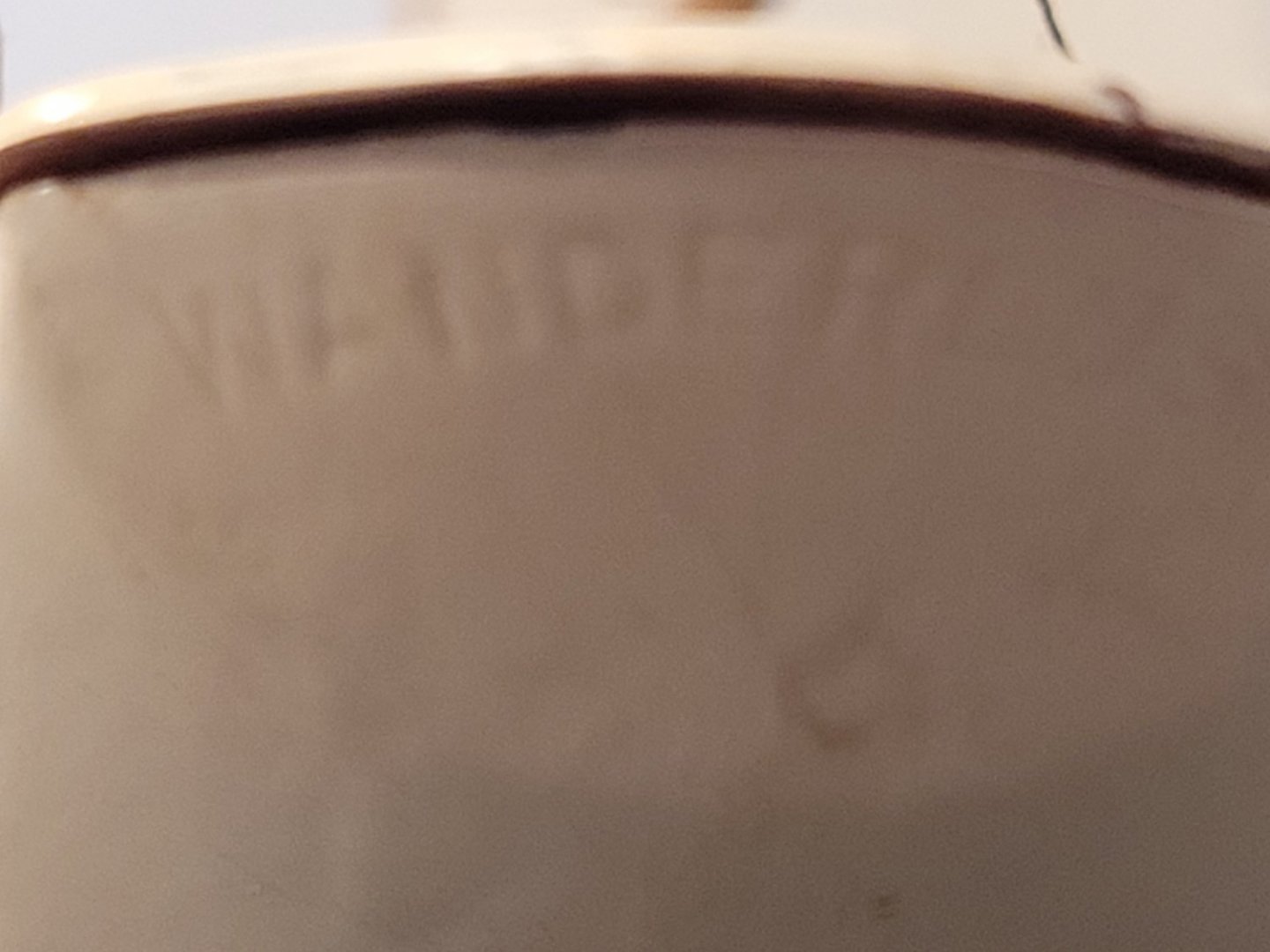
Folks, I've refurbished a few plastic models of famous schooners for a friend and I'm left with the boat described in the title. The father of my friend built all of these models in the 60s or the 70s and they were scrambled during a hurricane some years ago. I'm trying to collect information to help an accurate refurbishment of this particular boat and have not found anything on the internet. The name 'Wanderlust' appears on the transom but the picture is not very clear. If anyone has any information on the boat or the plastic model, I would be very appreciative. Thanks very much, Doug McKenzie


-
I've received word that Leon has arrived in Larvik in good shape - I have no details! Also I have received a link - https://colin-archer.no/LEON.html - to a history of Leon written by Jeppe Jul Nielsen. This material is now available for the first time and along with the technical details behind it, can now be used by any modeler interested in expanding Underhill's material to create an even more authentic model of Leon than was previously possible.
- 108 replies
-
- 1
-
-
- leon
- brigantine
- (and 1 more)
-
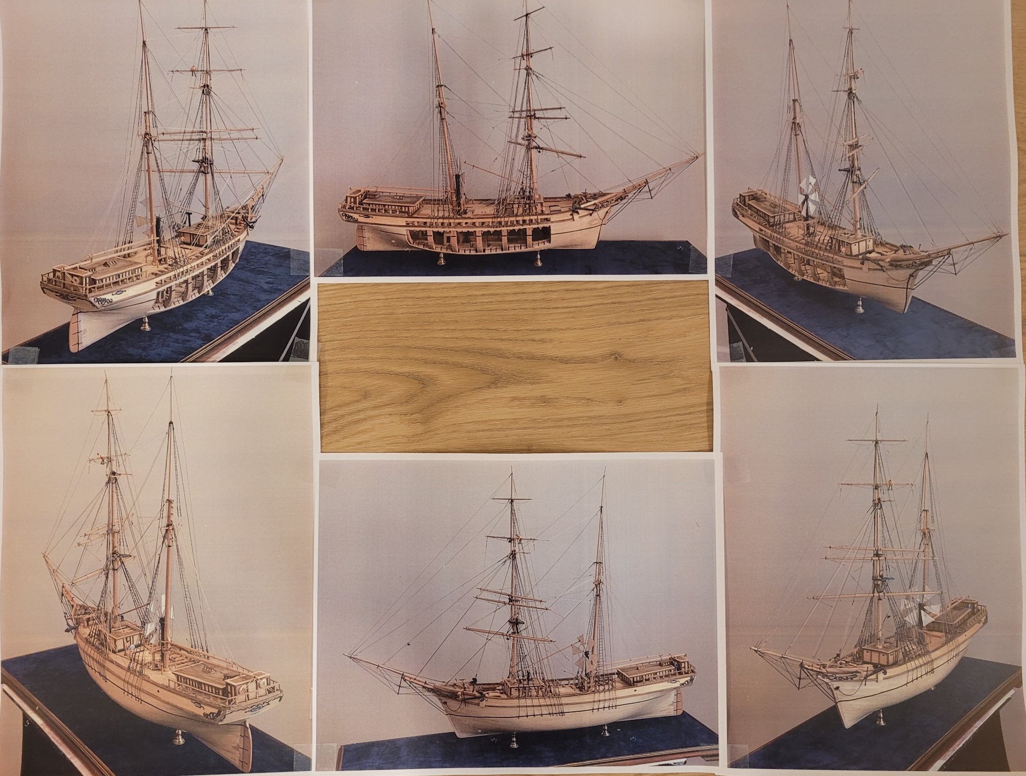
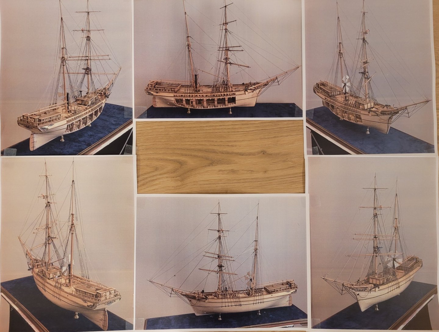
Thanks for all the kind words, folks. So I guess I was mistaken when I said the last post would be the previous one since THIS will be the last post. The reason another one is needed is because I failed to mention that Leon is being donated to a foundation in Norway, Tollerodden, which is helping to keep the memory and accomplishments of Colin Archer alive. He was the designer and builder of Leon. He built 4 ships (Leon was one and Fram, a polar ship, was another) but his reputation was solidly built on very successful and numerous pilot boats and rescue boats. The foundation is located in Larvik, Norway where Leon (original) was built in 1880. Please invoke whatever good luck mechanisms you find effective that Leon arrives in Larvik in great condition. To help me remember her we've had a 'photo' constructed that's kind of neat - 6 views of her in one picture: Some particulars will be in the rectangle in the center in the final picture. Since the research work of Jeppe Jul Nielsen was not available until the framing and outer and inner planking were pretty much complete, there were some details that couldn't be fixed on the model. The most important of these is the moulded dimension of the frames. The model frames (moulded) are 45% larger than the original. There are a few other interesting details. The beam's end supports on the original ship (and on the model) are 2 diagonal (aka angled) hanging knees rather than the common arrangement of 1 lodging knee and 1 hanging knee. I have never encountered this on any other ship nor has anyone I have spoken with. The windmill pump was very common on Norwegian (and possibly other Scandinavian ships) but I had never encountered them before this project. In fact, it was not until late in this project that Jeppe found proof that Leon had one. I failed to serve the entire length of the first port and starboard fore shrouds. Although this may not be noticed by many, it was a feature that I was looking forward to implementing from the beginning of the project. I didn't even notice this lack until I was putting on the ratlines. Other details that may be of interest are given in "Leon - Technical Details" (an attachment in Post #101). Thanks and good fortune to all Doug
- 108 replies
-
- 9
-
-

-
- leon
- brigantine
- (and 1 more)
-
This will be the last posting for this model of Leon as she is finished. There are two documents following. The first, Leon-Overview is just a short intro the Leon. The second, Leon-Technical Details, discusses how authentic is the model This document describes the research findings of Jeppe Jul Nielson about Leon and how those findings were incorporated into the model. LEON - Overview.docx LEON - Technical Details.docx
- 108 replies
-
- 14
-
-
- leon
- brigantine
- (and 1 more)
-
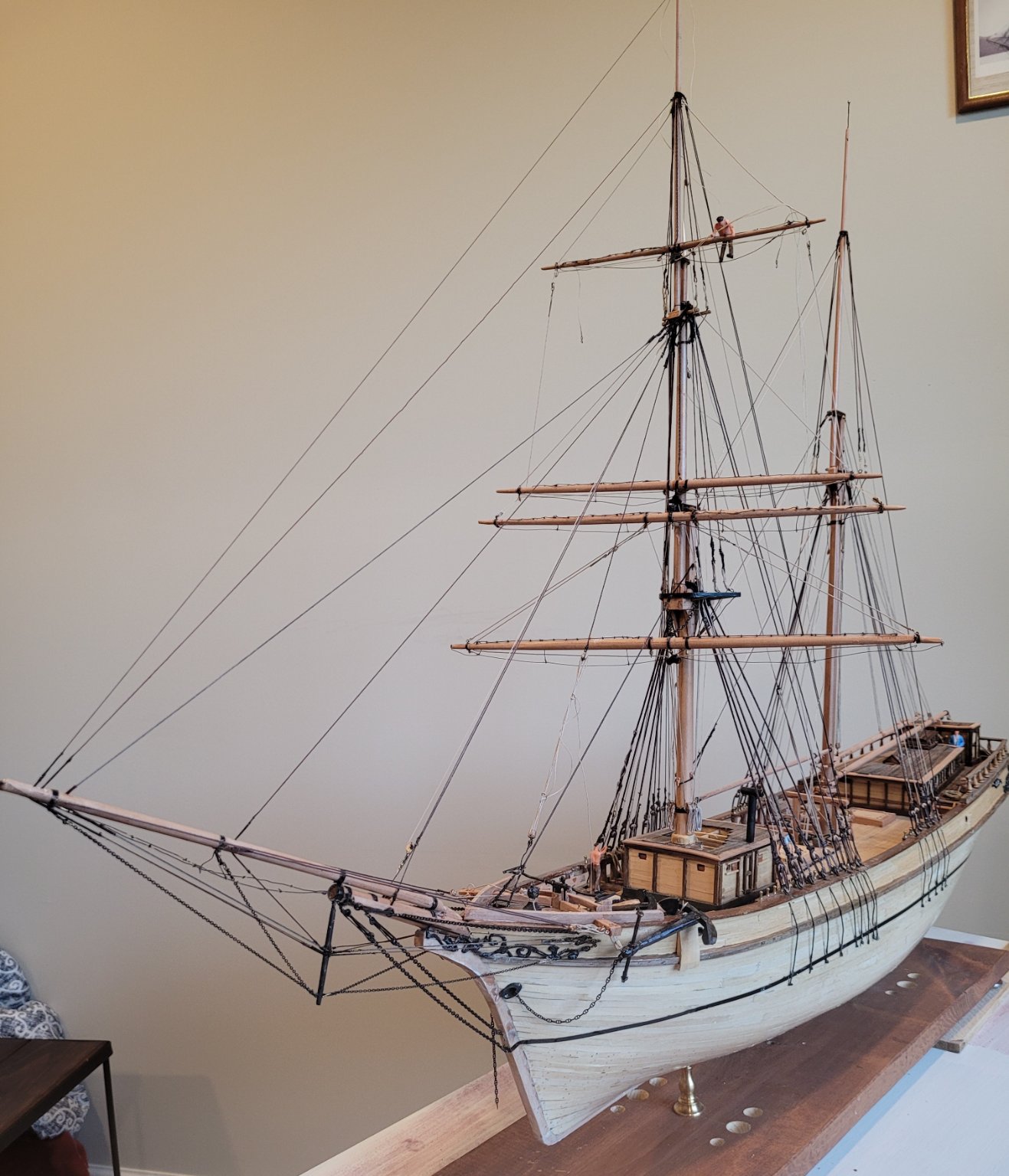
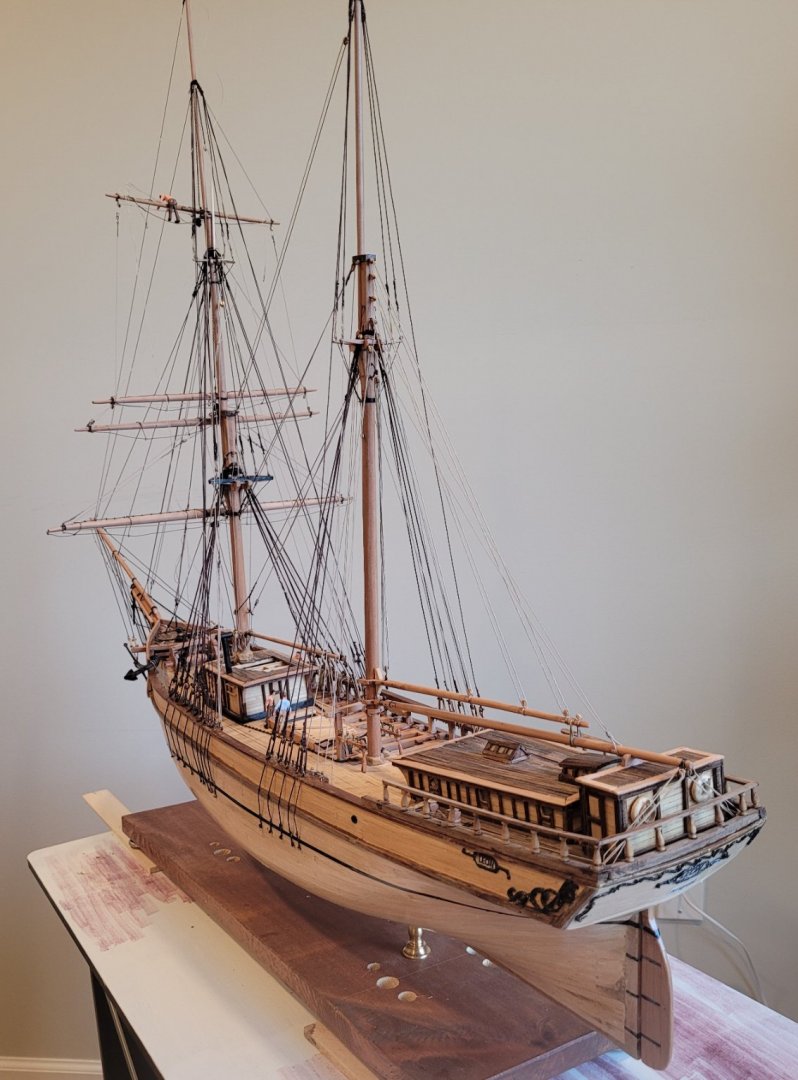
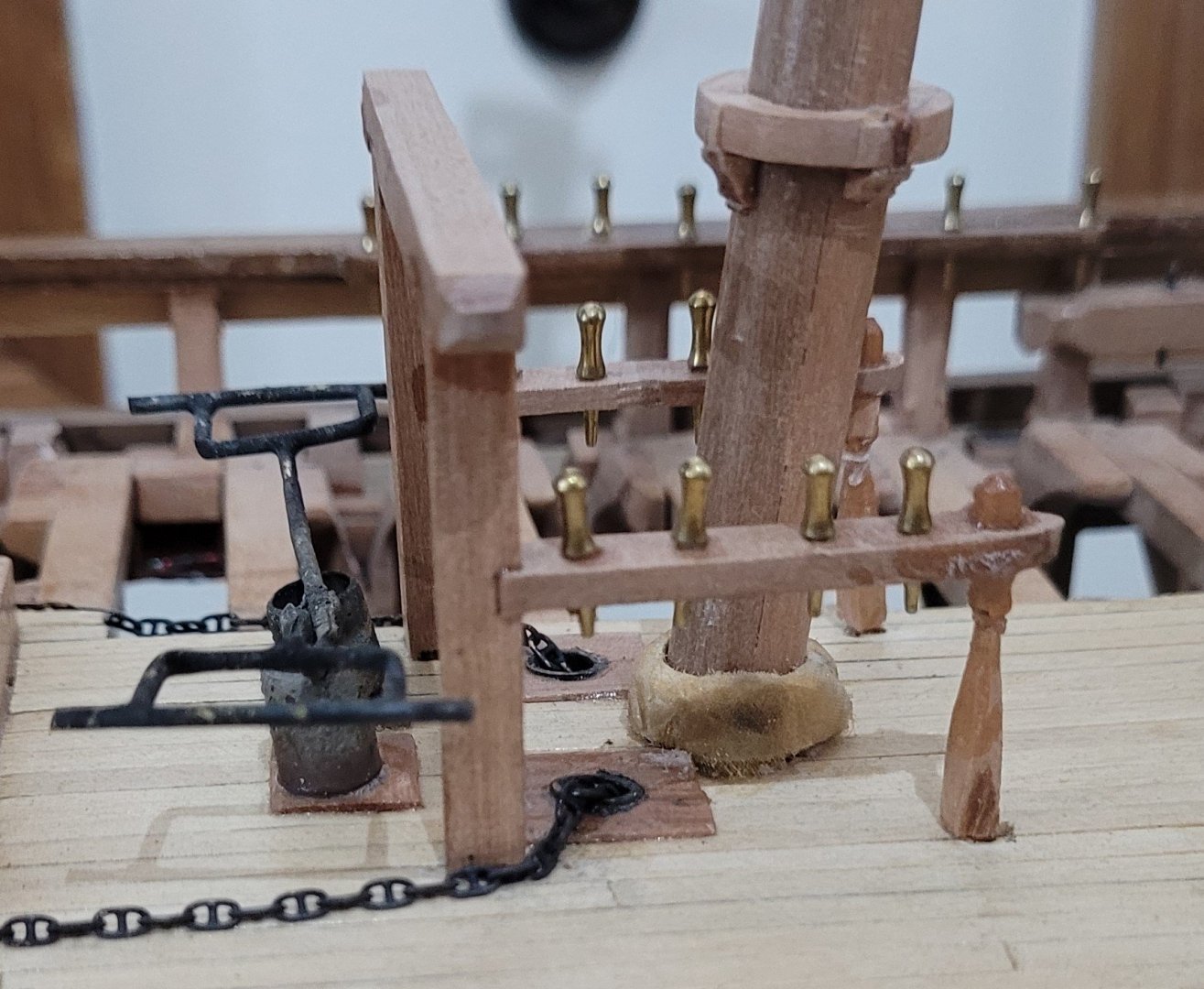
We are a little further on towards completion. The windmill pump is installed just forward of the mainmast. I should mention that some time ago we had a question of whether Leon had a windmill pump. We know now she definitely did because of a newspaper article at her demise and because Norwegian maritime law required she have one. The white card on the back of the starboard main shrouds is used to get proper spacing of the ratlines and rat boards. When the ratlines are finished we'll add the braces and be done.

- 108 replies
-
- 8
-
-
- leon
- brigantine
- (and 1 more)
-
Thanks very much Rob it's always nice to get positive feedback You seem to have a healthy respect and interest in Donald Mckay so I figured I would tell you that in high school and college Donald Mckay was kind of my hero of all heroes Your boats look absolutely gorgeous. One of my sons went to Webb institute And they have a wonderful model of Young America in the main lobby
-
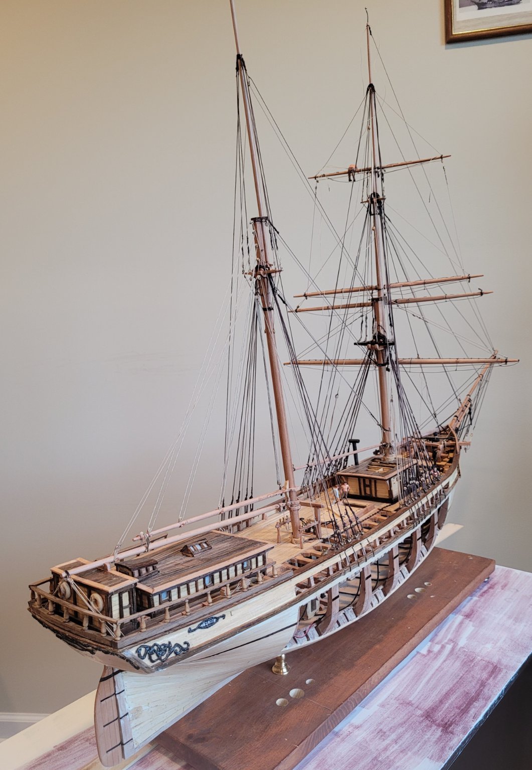
It's been about 2 months since we have had a posting and we are near completion so I figured I'd put up some pictures. What remains is some headsail halyards and downhauls, a starboard demo of how the anchor is brought aboard, the royal yard, a few backstays and ratlines. It may sound silly but the most enjoyable task recently has been figuring how long each coil on a belaying pin should be e.g. a staysail's downhaul coils a lot more line than that staysail's halyard.

- 108 replies
-
- 15
-
-
- leon
- brigantine
- (and 1 more)
-
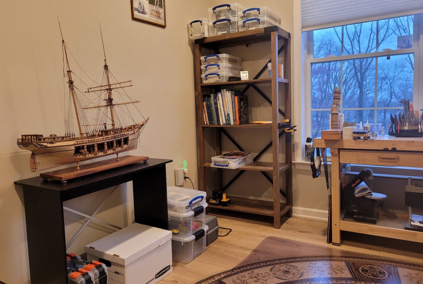
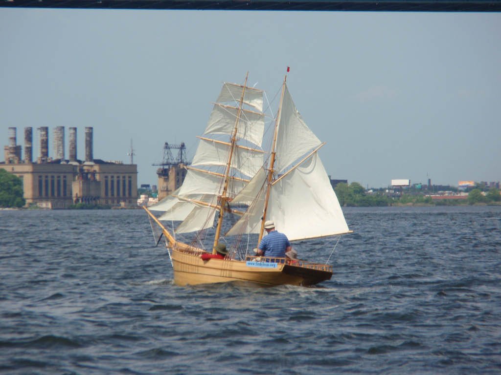
In responding to Matt D about "Little Leon" (the 1:8 sailing 'model') I have since learned from my wife that the 3 1/2 minute video is on YouTube. Here's the address: https://www.youtube.com/watch?v=gkJW7So95YQ You can see (from a distance) the square sails being furled in preparation to come about. What a wonderful 3 year project! PS My wife and I have just finished moving so a few more weeks of settling in and I'll be able to get back to Leon. The photo below shows Leon in her new home.
- 108 replies
-
- 3
-
-
- leon
- brigantine
- (and 1 more)
-
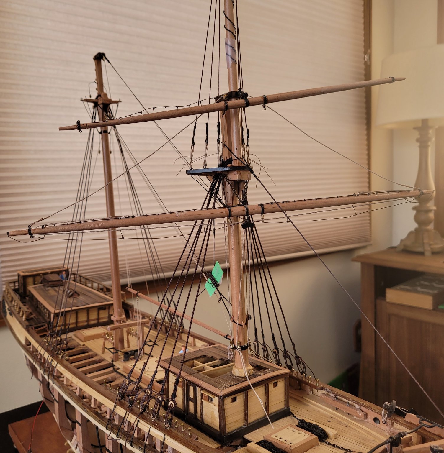
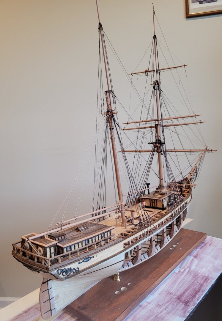
The main lower shrouds are done, the fore topmast is shipped and fitted with shrouds and the fore yard is in place. I considered not putting any yards in place until all of the standing rigging was in place but I realized that I could mount yards without getting in the way of other rigging too much so I'm doing it because I like the way it looks. For this picture, I have also included the fore lower topsail yard in order to show a different way that I'm making the jackstay. For the fore yard, I bent little pieces of wire around the jackstay but for the fore lower topsail yard, I soldered little pieces of wire to the jackstay making it a little less prominent. (The jackstay stanchions have not been put in their holes yet so they can be seen)
- 108 replies
-
- 4
-
-
- leon
- brigantine
- (and 1 more)
-
Matt D, There were some simplifications introduced to make sailing her feasible with just 2 people. All 5 braces were combined into a single line which was a big loop no ends. Pulling on on side of the loop brought all 5 yards around while the other side of the loop was free to pay out the other side of the yards. In addition, each sail had its buntlines combined into 1 line, looped, just like the braces. Pull on one line and all the buntlines are taken in furling the sail, In addition, both sheets were attached and paid out as the buntlines were taken in. To set the sail, you pull in on the sheets and the buntlines release. This arrangement was used on all five square sails. Lastly, the sheets of the outer jib, inner jib and fore staysail were all carried back to the cockpit, aft of the main mast to increase ease of sailing. The result of all of this is that she had a lot of mobility. She would wear ship very easily and she could also come about but that requires furling all five square sails and then resetting them after the maneuver was complete. I've got a 3 minute video of her sailing and coming about but I don't know how to put the video in this blog. Doug
-
Rhian, As far as what happened to Leon after her catastrophic leak in 1915, I don't know. I doubt if she was used in any normal service. I will ask my friend in Norway if any of the newspaper articles talk about that or maybe there was just a standard way of dealing with ships in that condition. As far as the lovely sail plan goes, this is one of five (I think) sheets of plans that Harold Underhill drew in the 50s I think. They are sold by Brown, Son and Ferguson. It might be that the copies of the original drawings are larger than the ebay picture - I can't tell how big the ebay picture is. A bunch of years ago I built a 'model' (1 to 8 scale) of Leon so that I could actually sail her. Here's a photo: Thanks for your interest in Leon, Doug
- 108 replies
-
- 6
-
-
-
- leon
- brigantine
- (and 1 more)
-
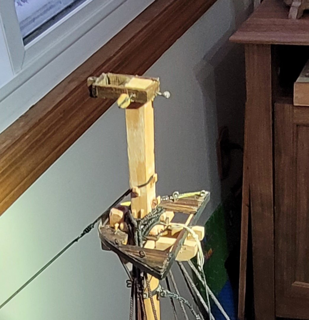
The rigging has started in earnest. The fore shrouds are up but the lanyards have only been adjusted once trying to get the upper deadeyes to be in line with each other. They will keep being adjusted over time. The fore stay is up also. Jeppe found a signed contract dated a month before Leon was launched which specified that the fore-aft stays were to be wire and the shrouds were to be rope. This is why the forestay is so thin compared with the shrouds even though it's doubled. The green cards help keep some lines which are not ready to be installed yet neat - these are the main stay, the main middle stay and the main topmast stay - these were fitted to the foremast before stepping the mast for ease of handling. At the end of the bowsprit are the martingale and the two heart-lanyard fittings waiting for the bobstay chain. The masthead shot below shows some of the details. My target is to serve everywhere that it was done on a full scale ship. So far there is one deviation. I haven't served the lower ends of the shrouds going around the top deadeye My serving material is 0.006" diameter thread, full scale 0.29" which is too big. Mostly, it seems to be OK but in conjunction with the deadeyes and the shrouds being rope it seems too big so the serving was left off. This is a good place to mention that the mast caps were probably iron but I have made them out of wood. The reason is simple - when I tried to construct them from brass or copper, my silver soldering skills were grossly inadequate. The dimensions of all rigging both standing and running were taken from tables in Underhill's Masting and Rigging the Clipper Ship & Ocean Carrier, In other sources we found that the length of a rope block should be roughly 3x the line's circumference. This formula was used to size all of the blocks.
- 108 replies
-
- 3
-
-
- leon
- brigantine
- (and 1 more)
-
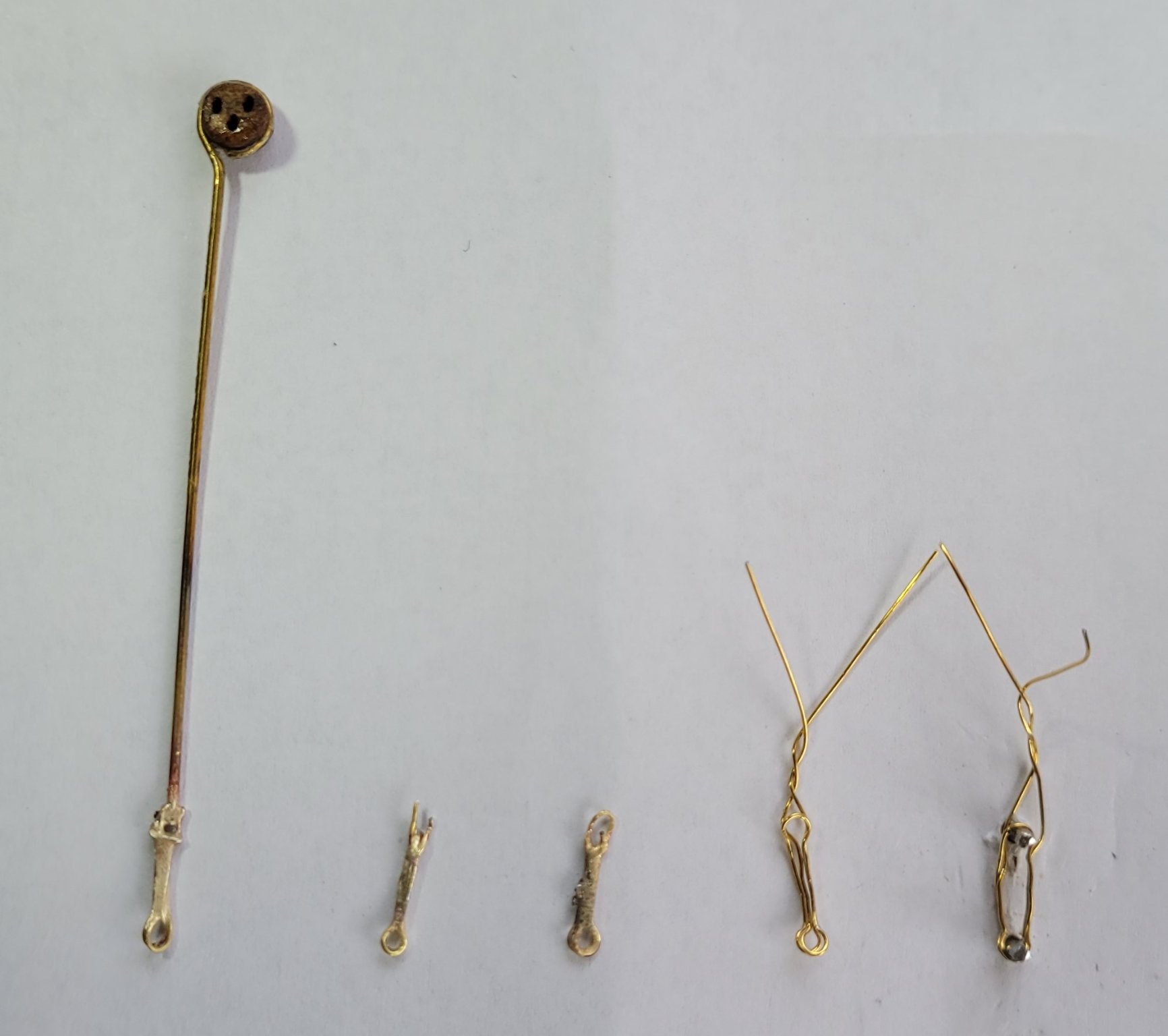
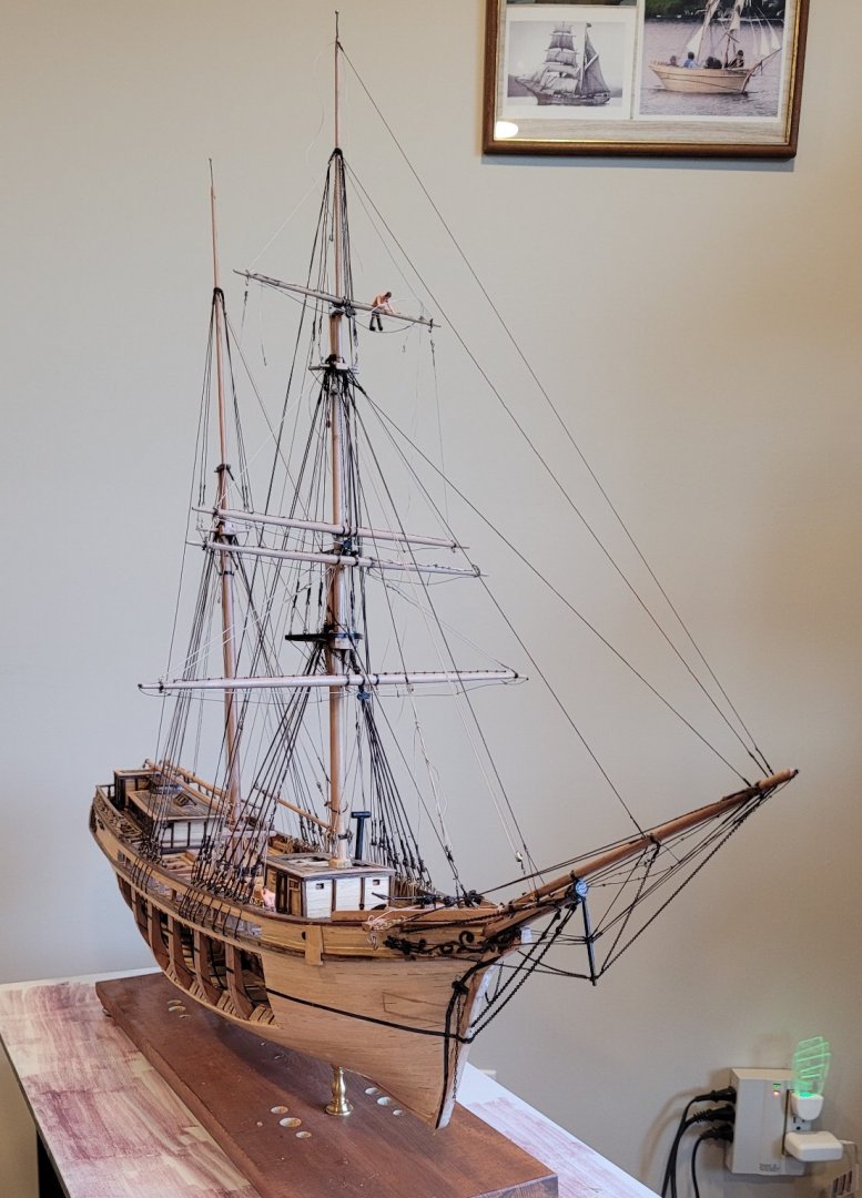
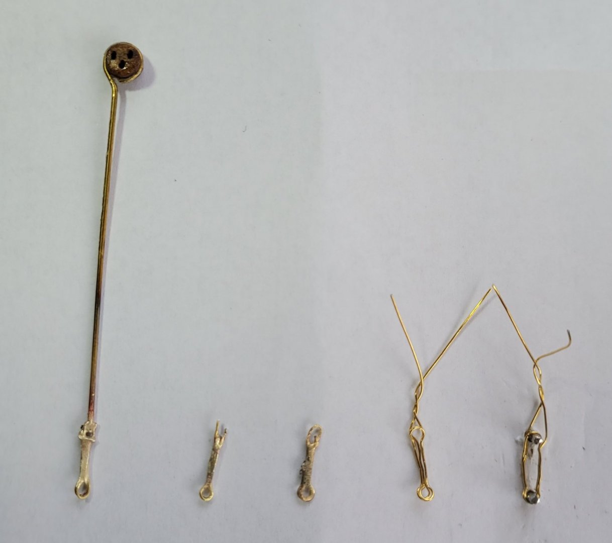
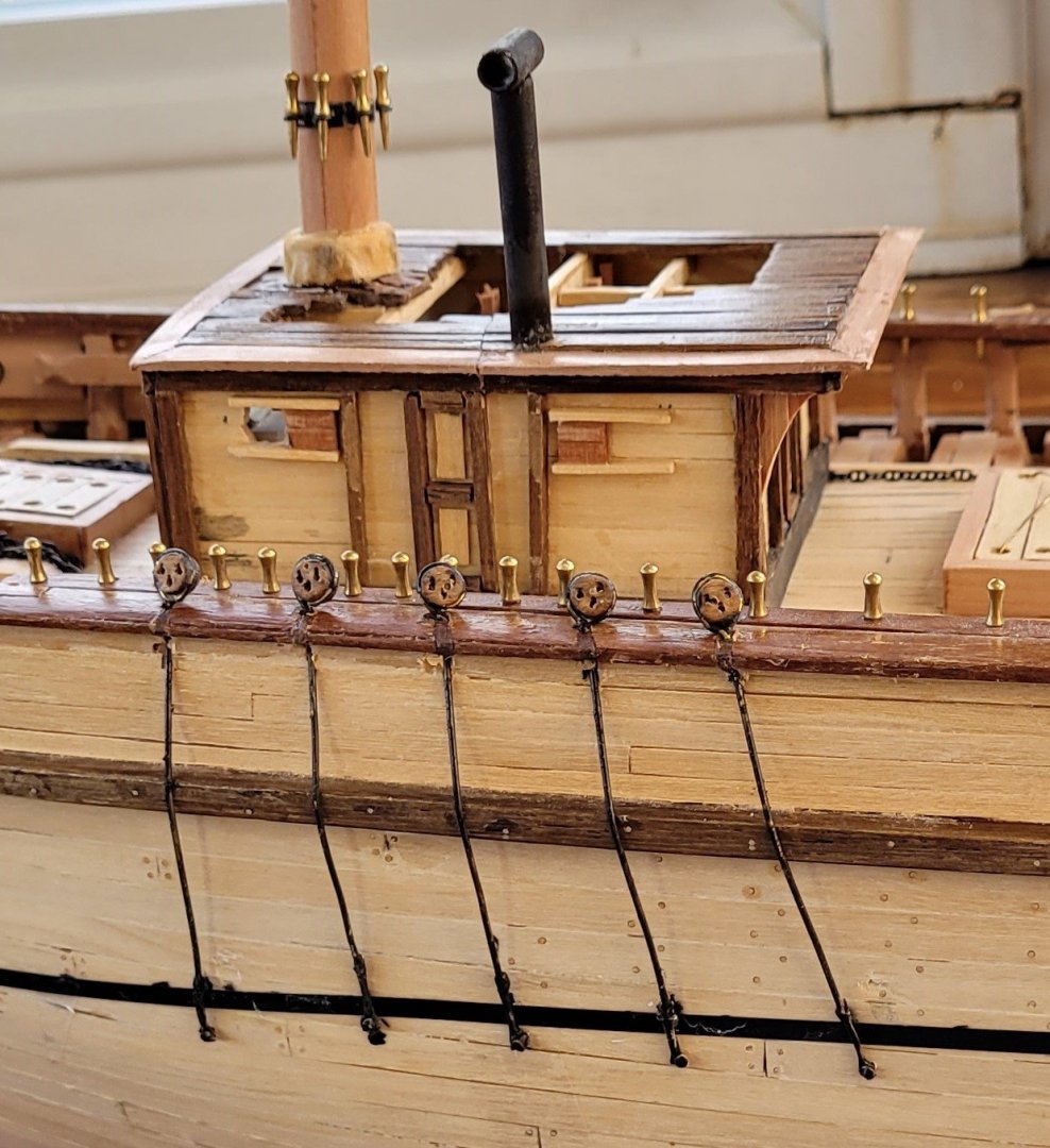
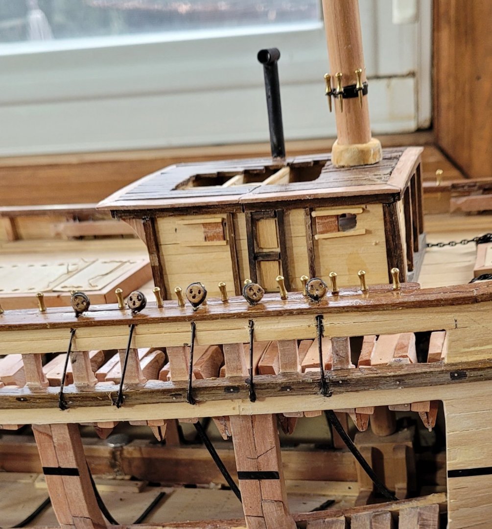
The two lower masts are installed, held in-place with wedges that are covered with the mast coats. In order to make the mast coats look like canvas a little fine material was varnished over the imitation mast coat made of wood. The two lower masts were installed so that the chain plates for the shrouds could be angled accurately. The backstay chain plates will similarly need the top masts to be installed. I had given a lot of thought, over a period of months, as to how I was going to fabricate the deadeye strops, the chain plates and the chain plate cleats (aka backing cleats) since my miniature metal working skills are very limited (my large scale metal working skills also). I settled on the following techniques: First, I used 1 1/2" round copper rods for the chain plates as Underhill made the comment that Leon had round chain plates (how he knew this is a mystery but it was very convenient for me). I wrapped this rod around the Syren deadeyes to form simplified strops. The chain plate cleats were fabricated along the lines of a posting in MSW for the Victory. (When I tried to find it again, to give credit, I couldn't find it!) In the photo below, we first see the 'strop' on the completed assembly on the far left. On the far right, a fine wire wrapped twice around two pins is the beginning of the backing cleat. Then, moving to the left, the wire is crimped between the two pins and then removed from the two pins. One more to the left and the crimped wires are soldered and the two tails are removed. The upper eye is one wire thick and the lower eye is two wires thick. One more to the left and the single wire eye has been cut forming two prongs. These prongs are straightened and soldered around the bottom end of the chain plate to complete the assembly. The thin wire was doubled in order to make the top of the dummy chain plate cleat about the same size as the lower part. The 5 assemblies for the port fore lower mast shrouds are shown in the next photo. Underhill talks about blackening brass (or copper) with thinned black paint. Up to now I have always used a chemical blackening agent but I figured I'd give the thinned paint a try. I found it easy and effective but not so durable as the chemical blackening agent. You can also see in this picture that little slots were cut in the rail to meet the holes that had been drilled. This allowed the entire strop / chain plate / backing cleat assembly to be fabricated off the ship and then installed finally plugging the slot. On the starboard side the viewing ports do not permit the full chain plate assembly to be installed so the chainplate is bent around the wale and terminated there as seen in the following photo.
- 108 replies
-
- 2
-
-
- leon
- brigantine
- (and 1 more)
-
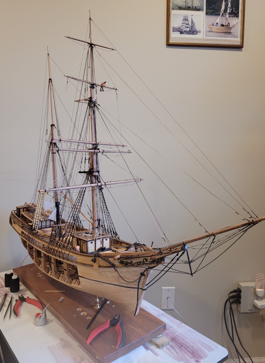
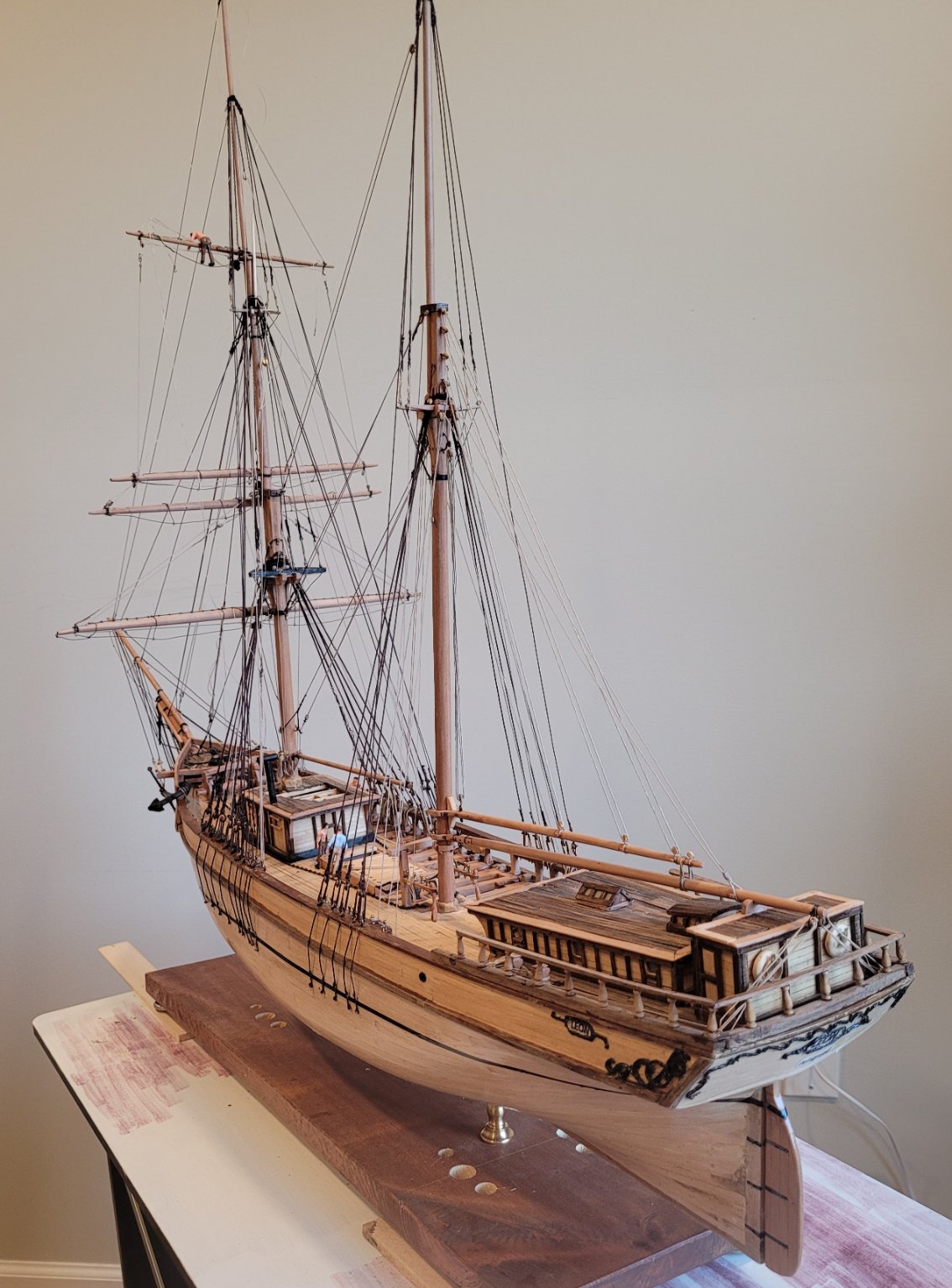
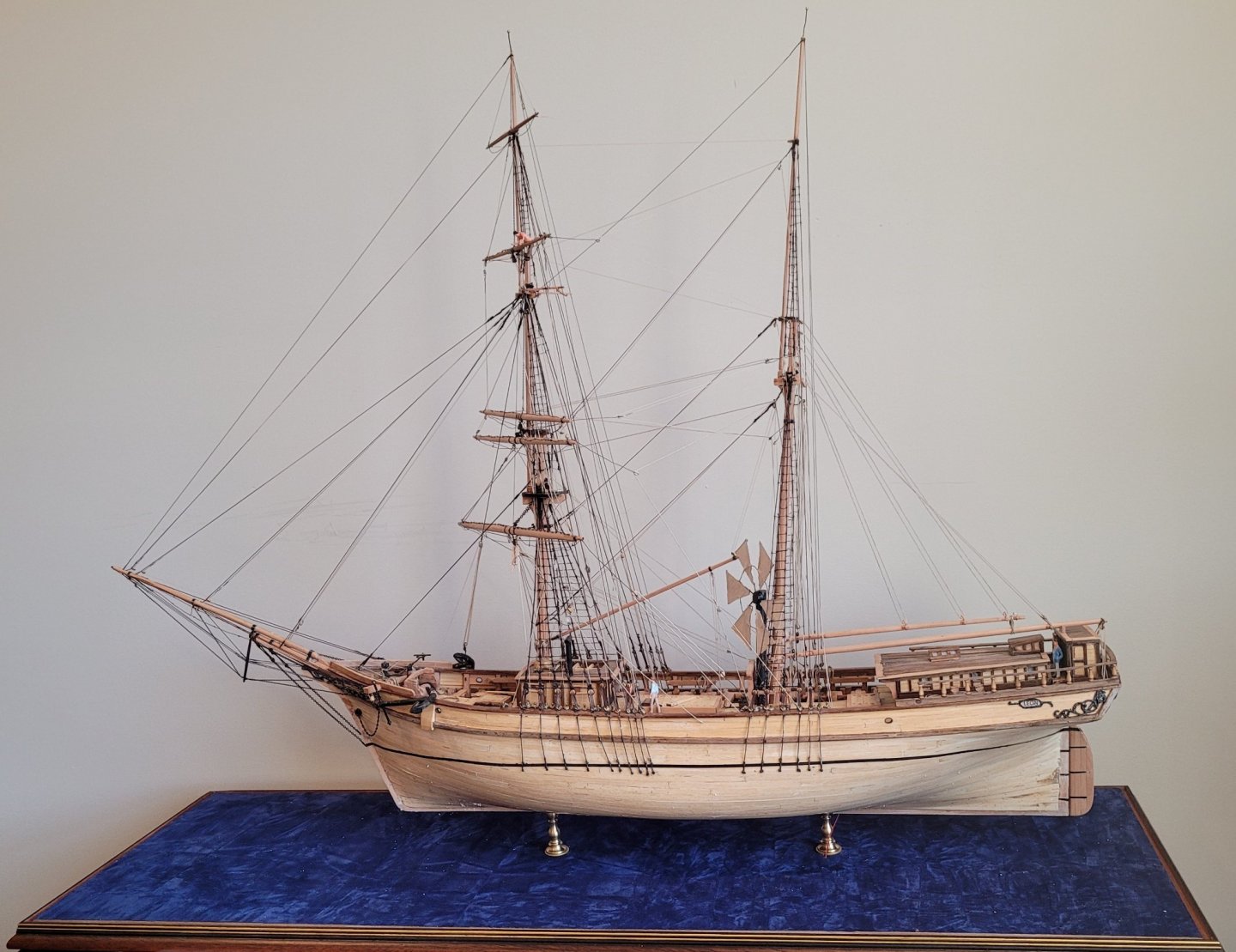
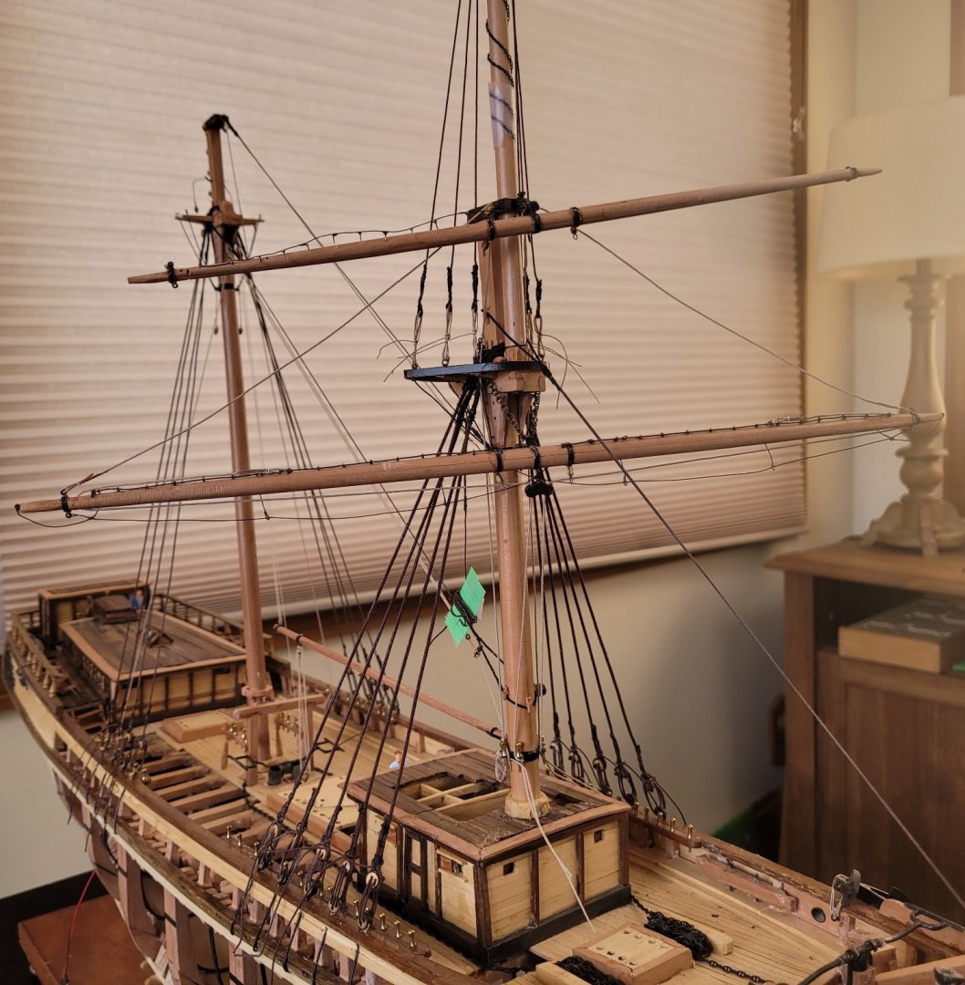
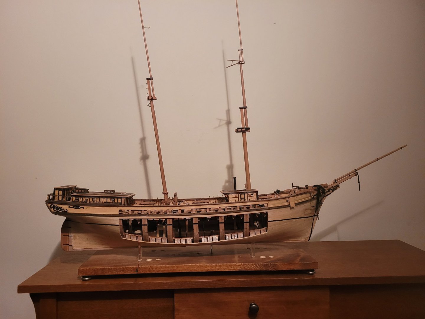
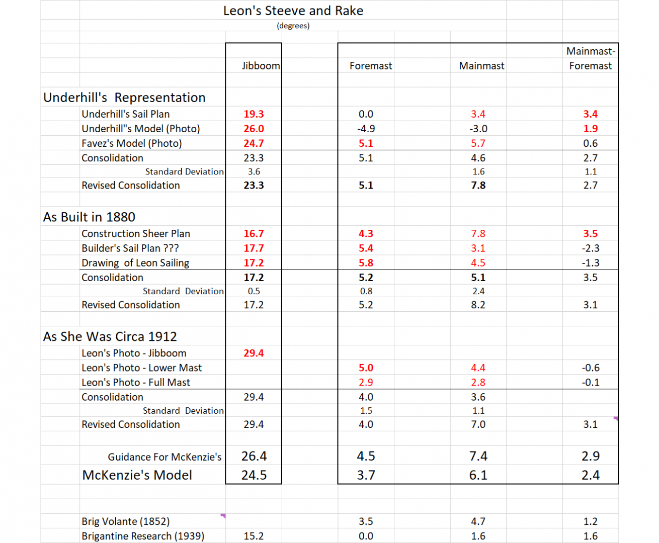
The steeve of the jibboom / bowsprit and the rake of the masts (along with sheer) are some of the first impressions that an observer gets of a model sailing ship. I noticed almost immediately that the jibboom in Underhill’s plans seemed a lot flatter than the jibboom in the well-known photo of Leon. I figured I could do some research and get a better idea of what these parameters really were. The photo below shows the model with masts done except for some paraphernalia. The steeve and rakes are selected based on the research documented below. The picture was taken so that the camera was nearly on the same level as the waterline and as directly off the beam as possible. These conditions provide the best estimates for the 3 angles. Values for the other photos are likely more error prone for not satisfying these conditions. All the numbers are in the picture below. We’ll talk about just the jibboom because it is the simplest and yet still gives a good idea of what the research entailed. The masts are more complicated because there is more variation between the sources and also we consider not just the rake of each mast but the difference in the two rakes. A note on the use of one decimal place for the angles - it is not meant to imply great accuracy rather it makes it ease to see exactly where a number in the text comes from in the table below. It's a trick from actuarial practice which was the profession I retired from. The first step of the analysis was to divide the variety of sources into 3 categories. The first is what values was Underhill basing his plans on. The second is what values were used in 1880 when Leon was launched. The third is what values were appropriate later in her life in 1912 (the year of her photo) when she was 32 years just three years before she was lost. Beginning the research, I had no idea that there might be changes in these angles over time, but I think there were, at least in the jibboom steeve. 3 sources were identified for determining Underhill’s values. 1-- Underhill’s plans, 2-- A photo of Underhill’s model and 3-- A photo of his friend’s, Favez, model. The two model photos are consistent (26.0 and 24.7) but Underhill’s plans (19.3) is lower by about 6 degrees. All these values are in degrees. A question arises as to why both models are significantly larger than Underhill’s plan. It is easy to imagine that when building their models, the photo of Leon was disconcerting as it’s steeve is significantly steeper than Underhill’s plan. 3 sources were also identified for determining the As Built in 1880 values. These three sources are quite consistent. The Construction Sheer Plan gives 16.7, the Builders Sail Plan (my term) gives 17.7 and a drawing of Leon under sail gives 17.2. Only one source is identified to determine the values As She Was Circa 1912. The well-known photo of Leon gives 29.4. Absent any other explanation for the increase in steeve angle of 12.2 degrees, maybe it was a change made during a refit. The rakes of the two masts As She Was Circa 1912 are much closer to their As Built in 1880 values being about 1 degree less.
- 108 replies
-
- 2
-
-
- leon
- brigantine
- (and 1 more)
-
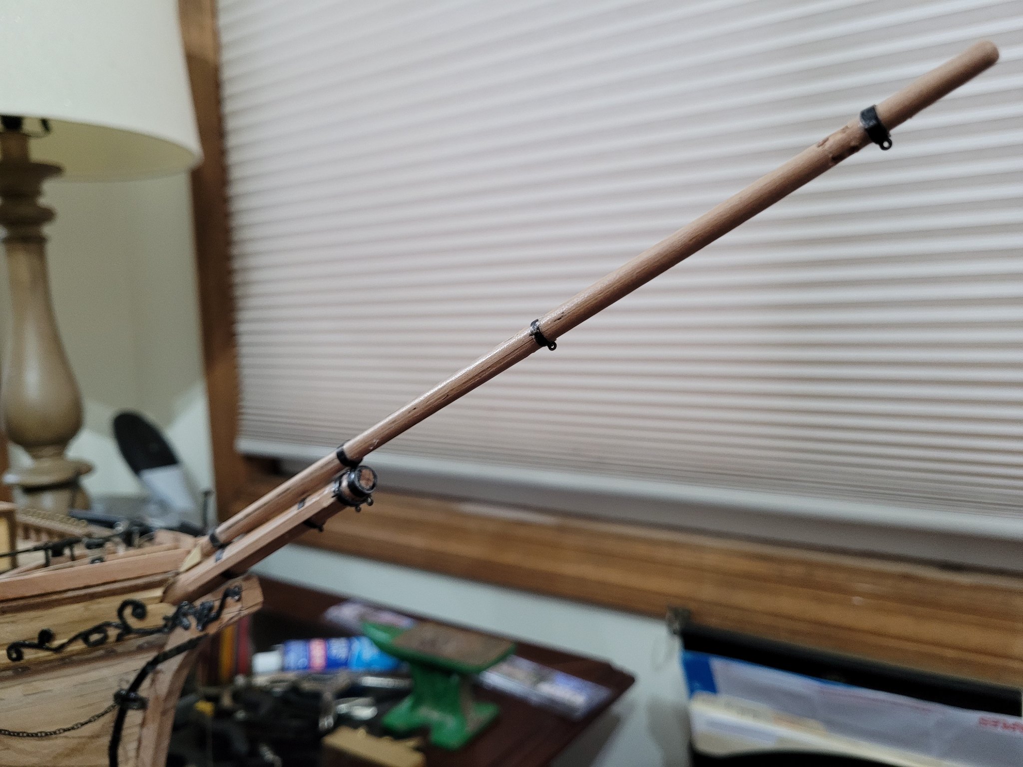
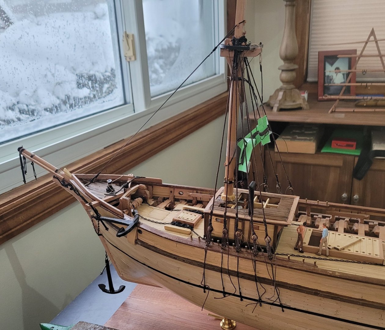
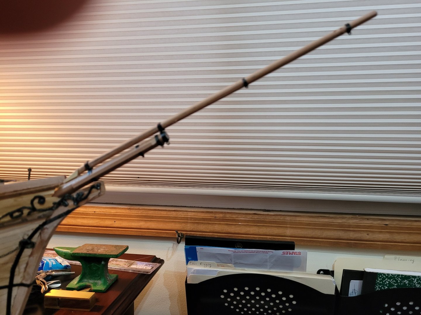
I've started on the spars beginning with the bowsprit and jibboom. I don't yet feel up to the metal work for the bands so I used Chartpak Graphic Art Tape (matte) from Amazon. I have 4 width - 1/32" 1/16", 3/32" and 1/8" (full size 1.5", 3", 4.5", 6"). The adhesive is not all that strong when wrapped so I use CA also. If a band has eyes, an eye is used to tack the end of the tape. If there are no eyes, mini nails (3/32" long) from Micro-Mark are used. Two sizes of eyebolts are used. The most common is 1/32" (full size 1.5") and less common 1/16" (full scale 3"). Both come from Bluejacket. The second photo is taken a bit off the starboard bow to show some of the eyebolts more clearly. In addition, the focus is much better on this photo so zooming in gives a sharper image . I should also mention Drill Bits Unlimited. They supply drill bits that are normally used in machinery but can be used in a pin-vise or drill press. They come in many small sizes. These drill bits are very sharp and very brittle - they break frequently. However, with care, they are a blessing to work with. Incidentally, in these pictures it looks as if the jibboom is tapered towards it's heel rather than it's head - please believe me, this is an illusion. A detail for research - I tried to find how the battens were fastened to the bowsprit - I assume it was with bolts or such. But I found no information so I left them blank.

- 108 replies
-
- 4
-
-
- leon
- brigantine
- (and 1 more)
-
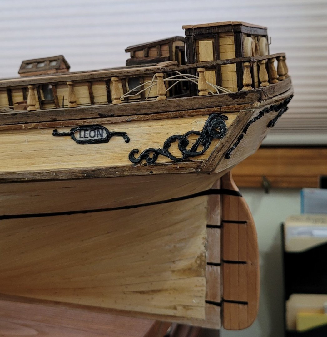
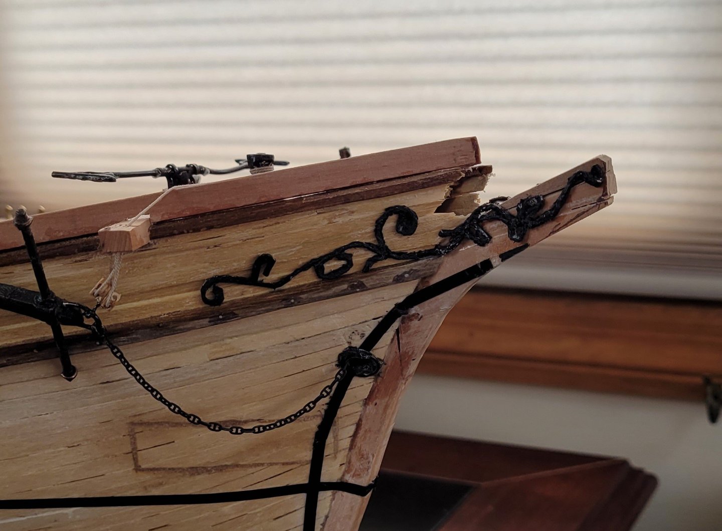
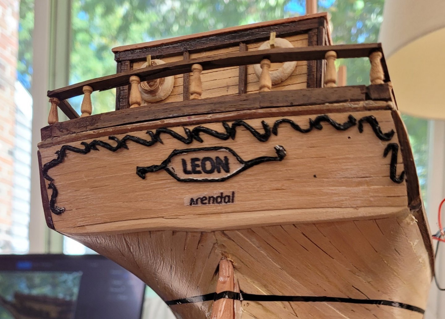
All the scroll work is finished - first shown is the quarter board, then the trailing board and finally the transom. The only new technique was typing the name and home port on tracing paper and then adding the actual scroll work. When gluing the finished work to the hull the tracing paper should have a very thin layer of glue. Then the wood becomes visible as seen on the transom. If this is not done then the tracing paper itself is seen as on the quarter board. Thanks again to David for his suggestion of string and gesso!
- 108 replies
-
- 1
-
-
- leon
- brigantine
- (and 1 more)