-
Posts
981 -
Joined
Content Type
Profiles
Forums
Gallery
Events
Everything posted by Martes
-
Captain of the Etna wrote: In the three months that I sailed her, I found that she steered perfectly well, that she carried the sail sufficiently and waved in the wind. Its most advantageous course is the closest with a fresh wind, she rarely fails to tack, with the wind ahead, and loses very little when tacking, the movements are very gentle and the mast only tires by its extreme height. At least that's what Google translate gives me I think a similar description for the Salamandre may be present on page 63 of the book, but the text is in handwriting and it's very difficult to make out with my very rudimentary knowledge of French terminology.
-
@Lieste, I had some thoughts if I can substitute the 6pdr (French) guns on Salamandre with 32-pounder carronades - after all the battery is relatively low, the ship framing is very heavy, but the basic establishment for a bomb vessel was 24-pounder carronades. And there should be something on the upper deck - 12-pounder carronades, maybe. Do you have any information about how a French-built bomb ketch would behave under sail? Speeds, maneuverability? The book says Etna was quite handy, while the handling of most of the British ships of this class was very lamented.
-
You have a config file, that indicates the hull model, the textures (damage set, colour per country, if you want it to by dynamic), the positions of masts, sails and flags. For Constitution that would be something like 44gfrigate_us.cfg Then you have a database (usrships.cfg), where you set up named entries, that contain the ship's data, weapons, etc, and references the cfg file. When constructing a scenario in the editor you insert an entry from a database. Of course, you can add/remove/copy/edit database entries.
-
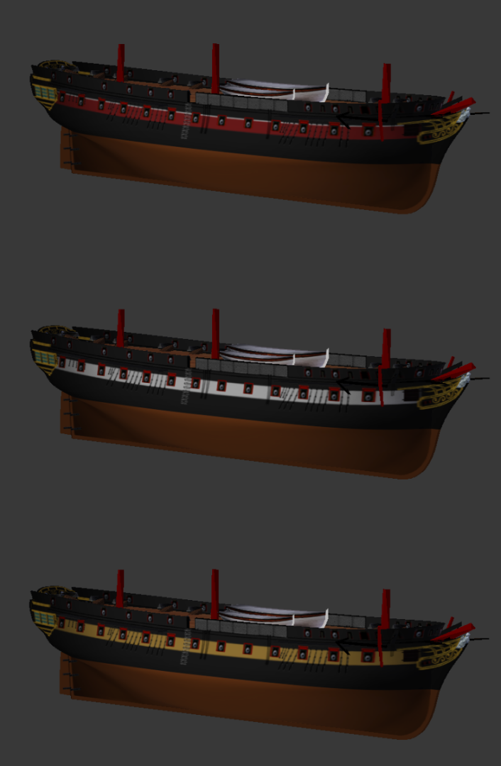
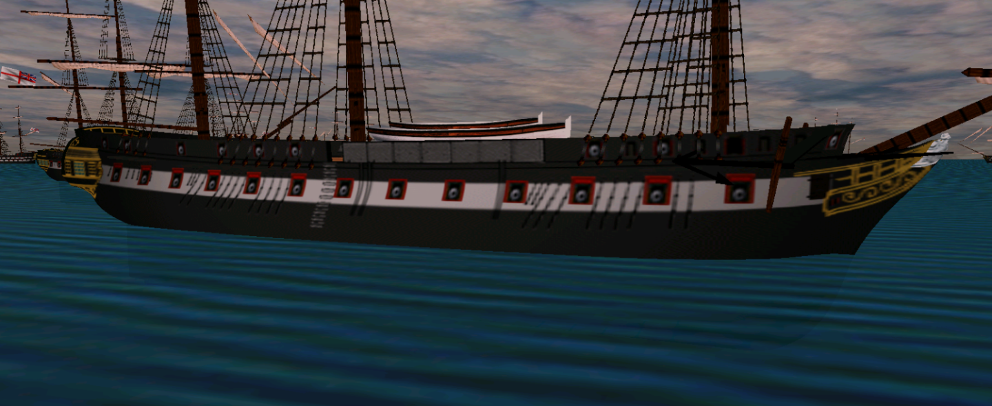
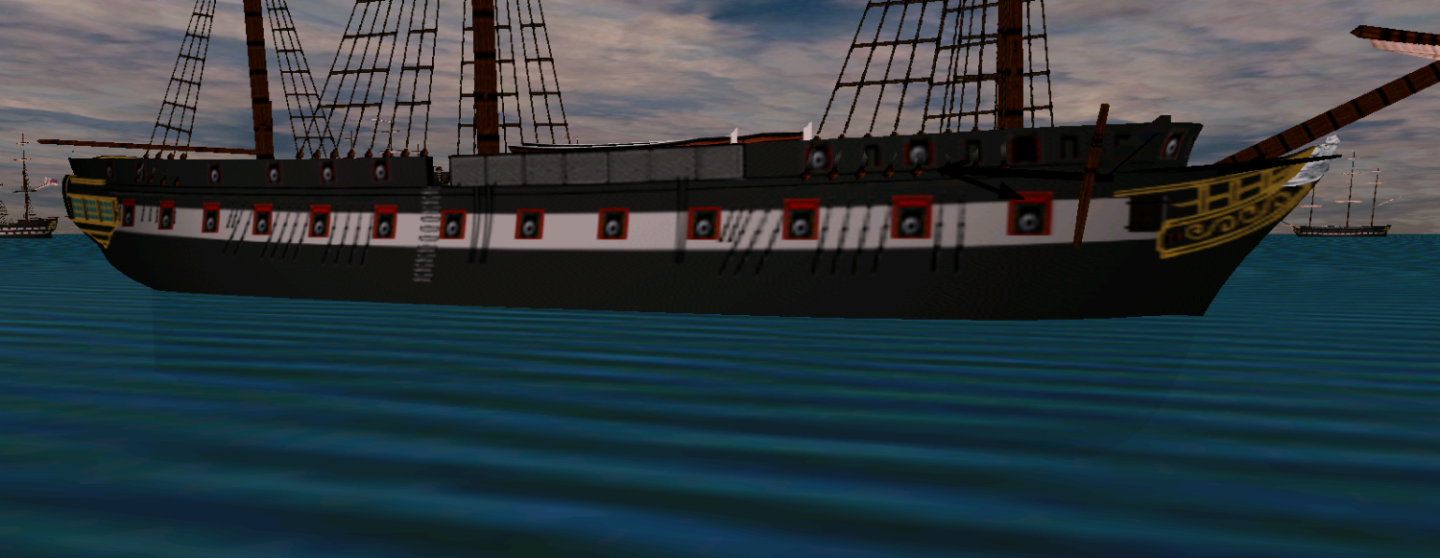
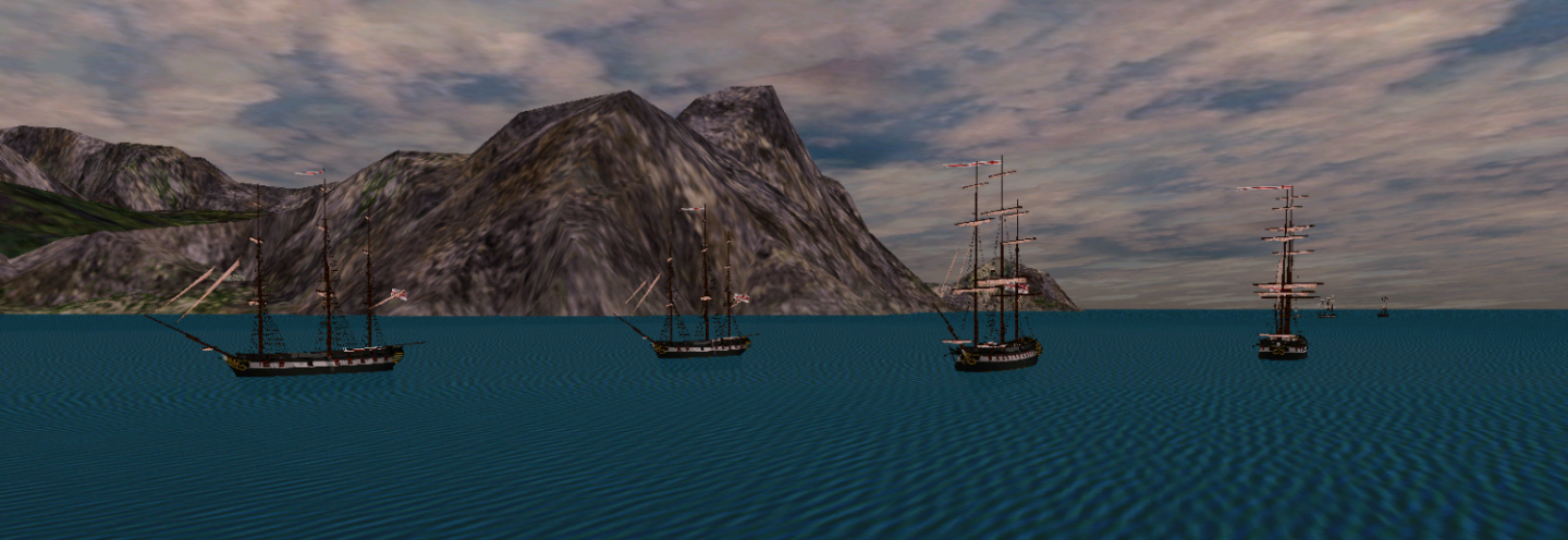
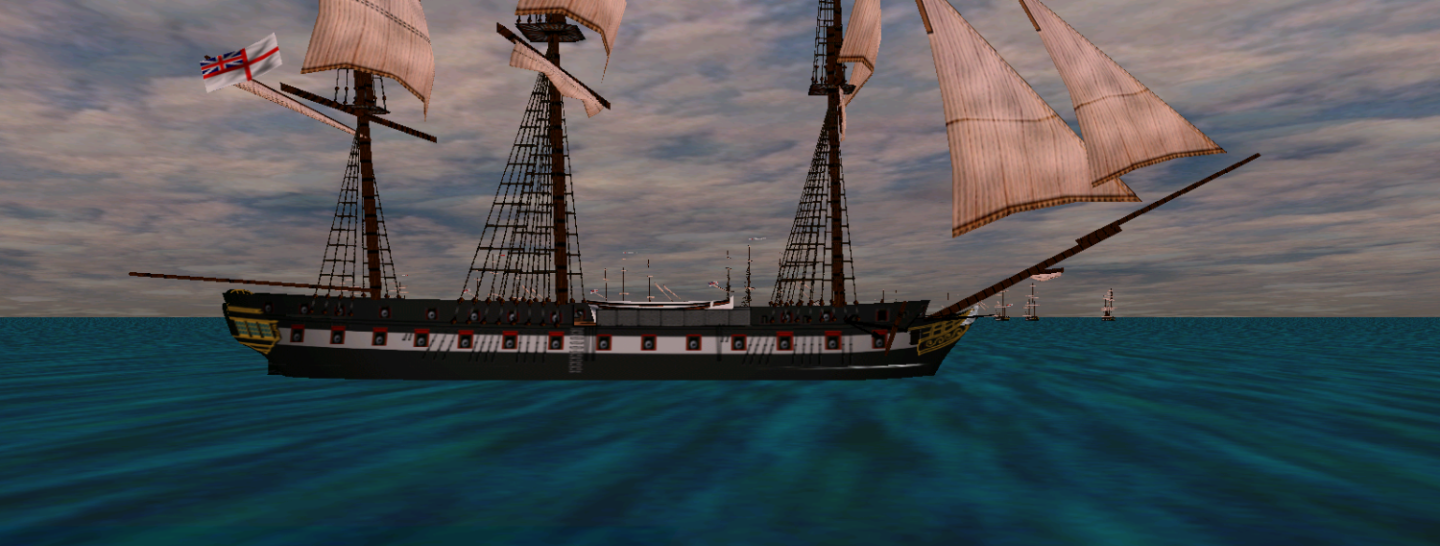
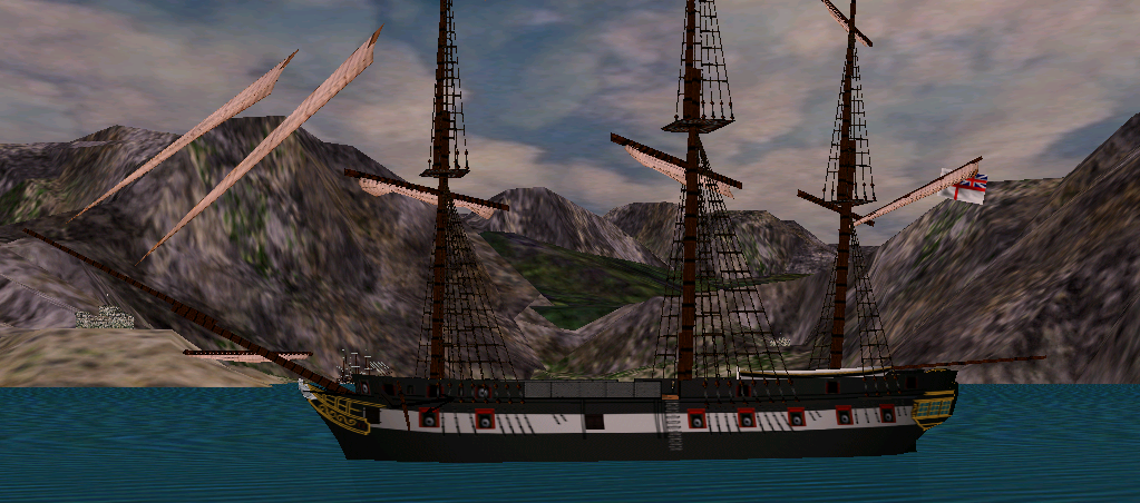
Each model is done in three paint schemes - yellow, white and red-with-narrow-white stripe. Then it's just a question of the config file selected for the ship in database. I just like the white better than others, so they feature on the screenshots mostly. What I didn't try is earlier variant, covering the upper bulwarks in blue or red with gold decals, but it seems a little bit too archaic.
-
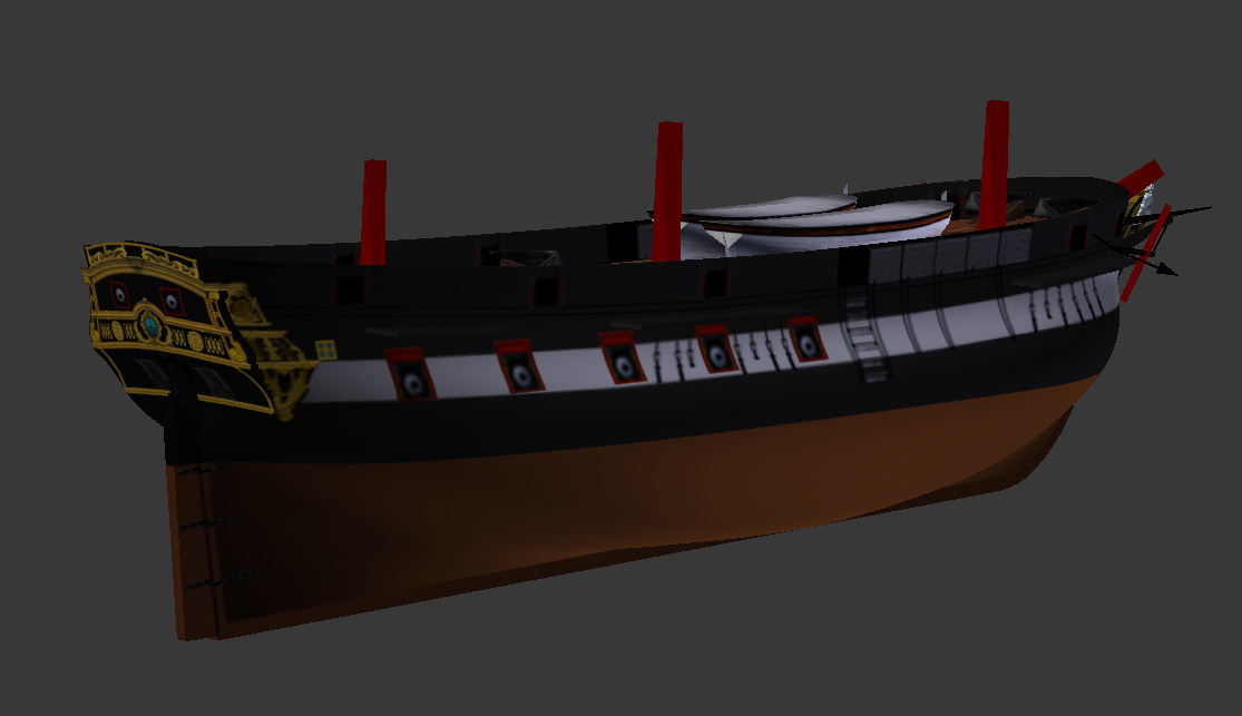
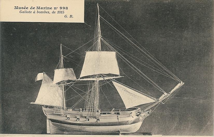
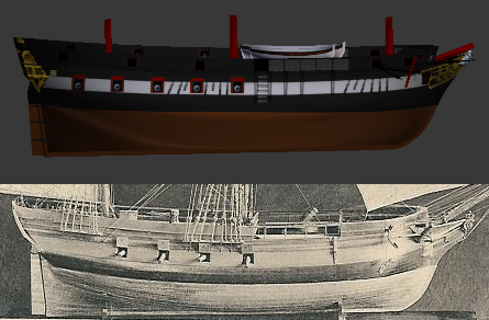
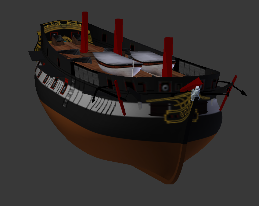
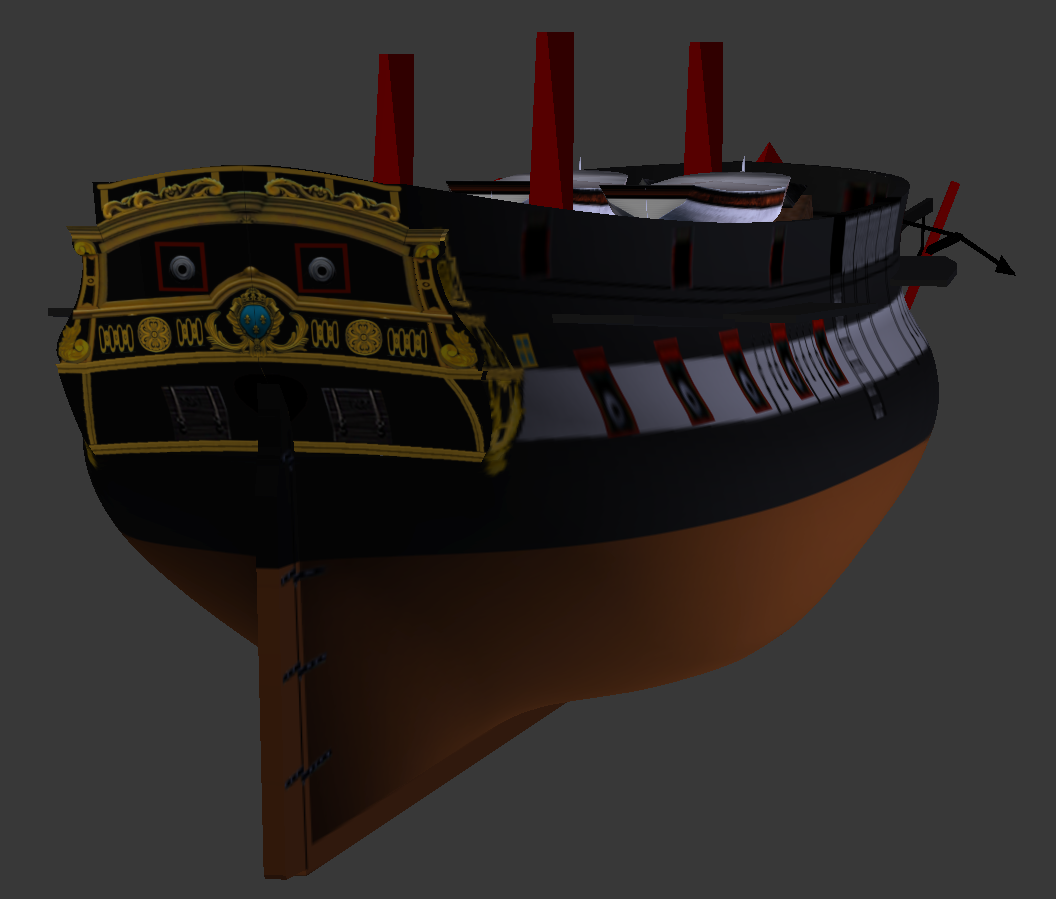
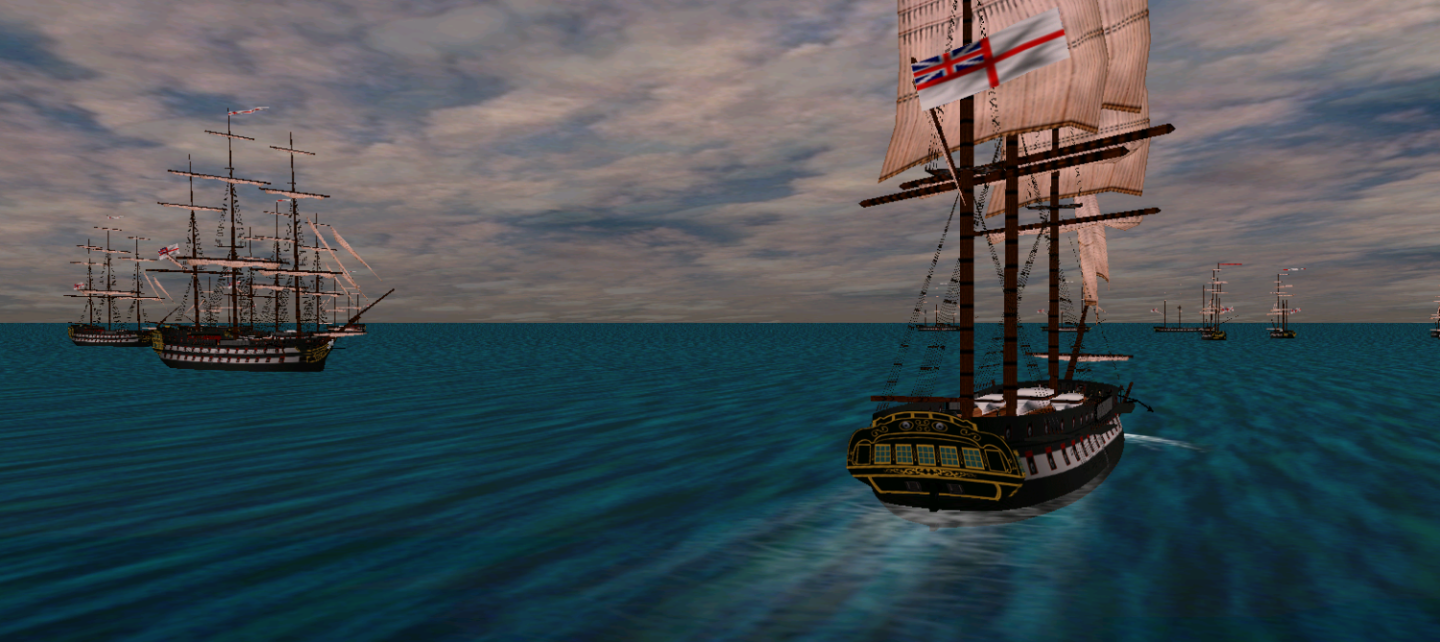
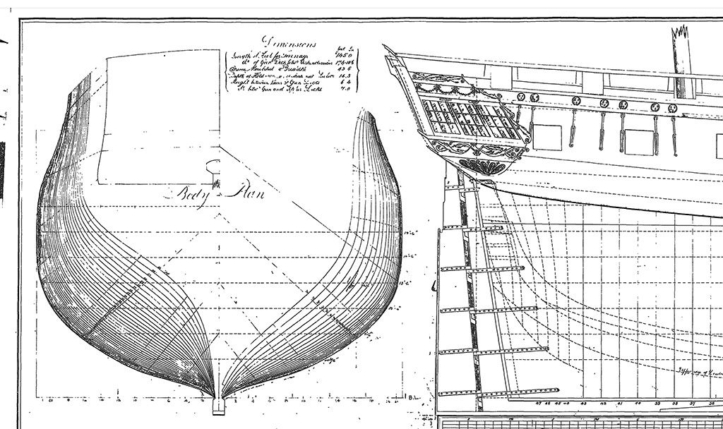
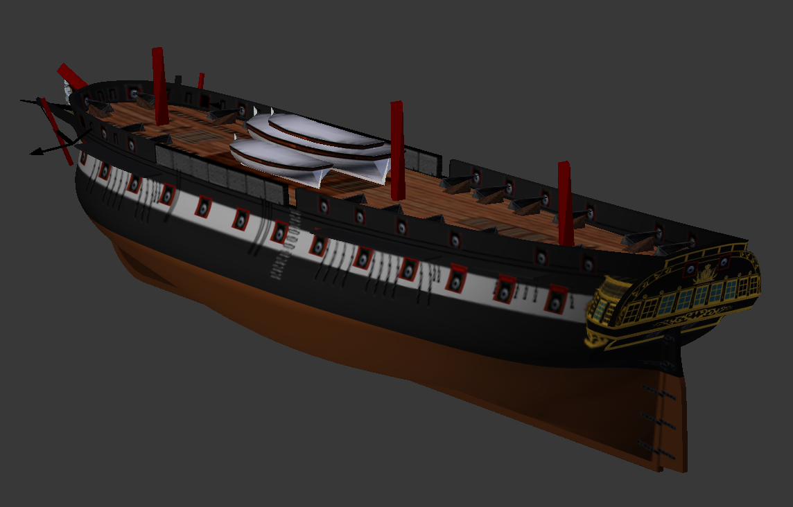
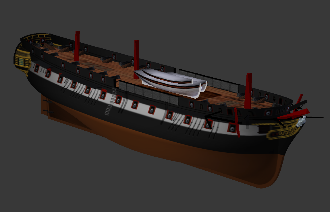
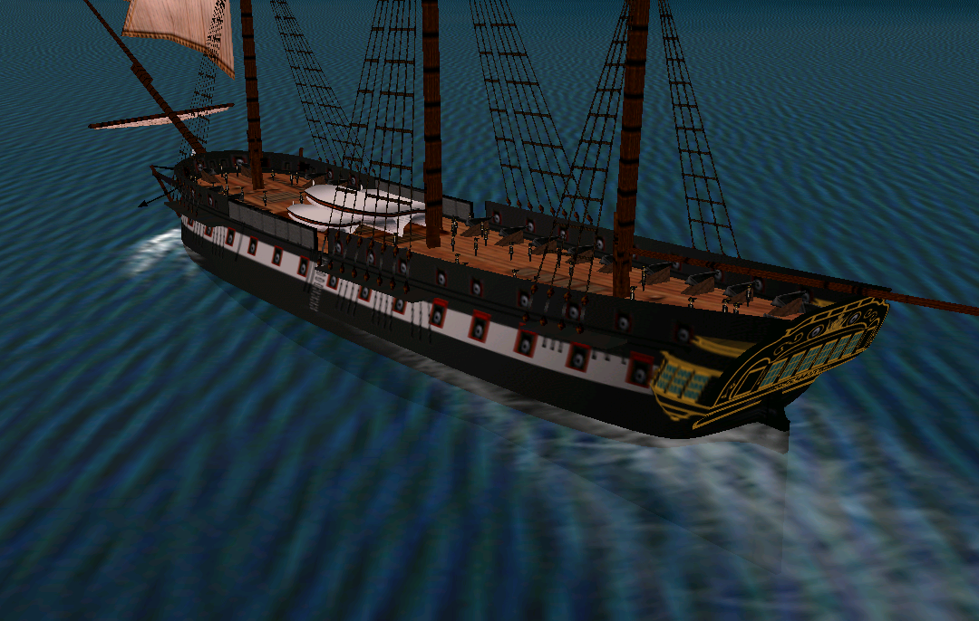
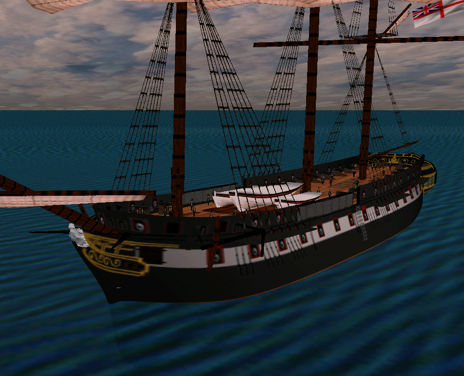
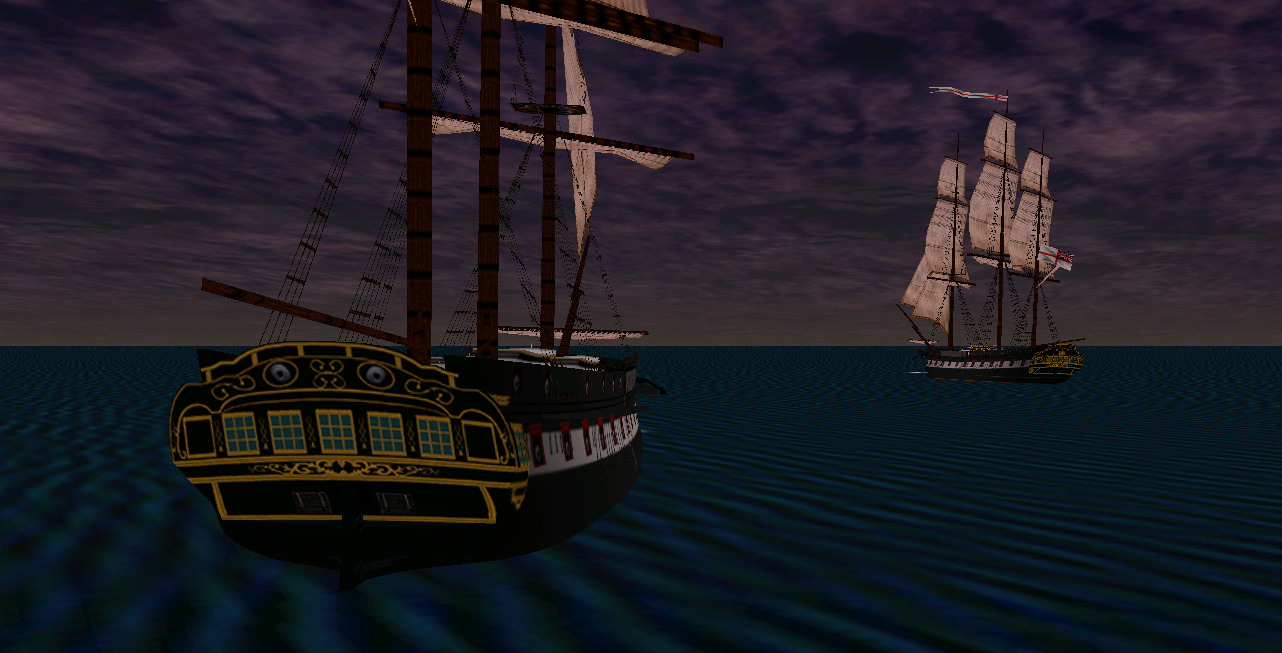
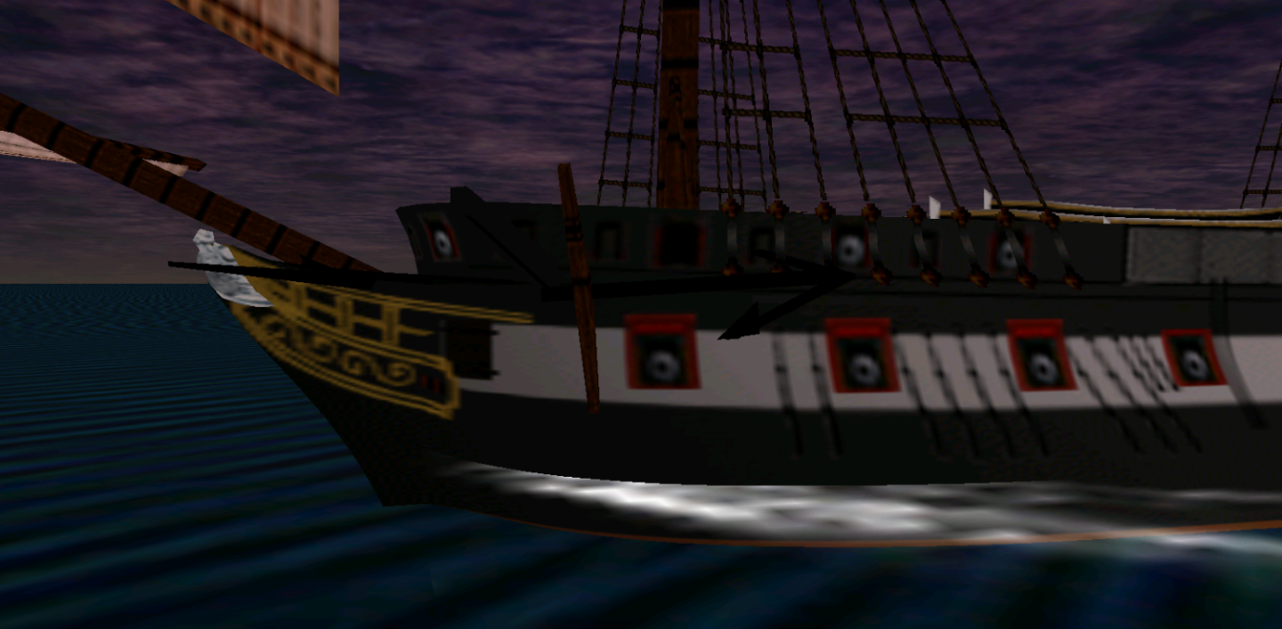
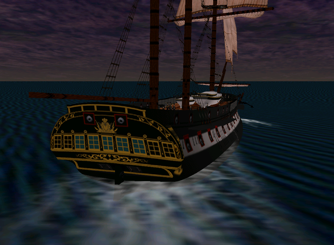
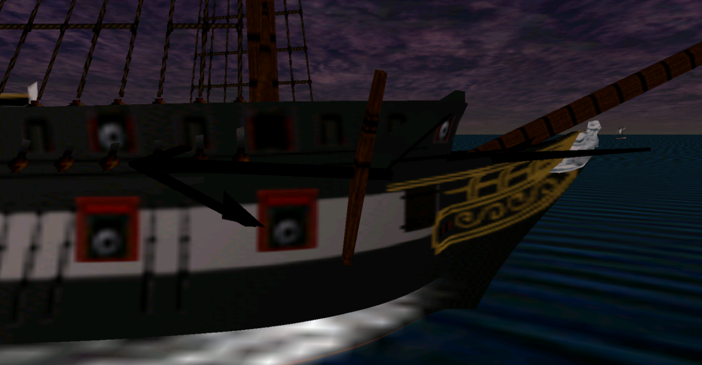
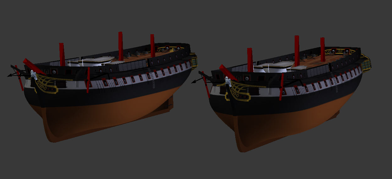
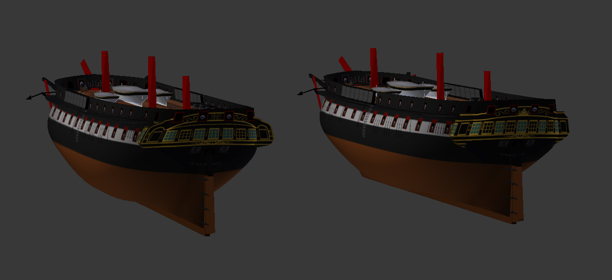
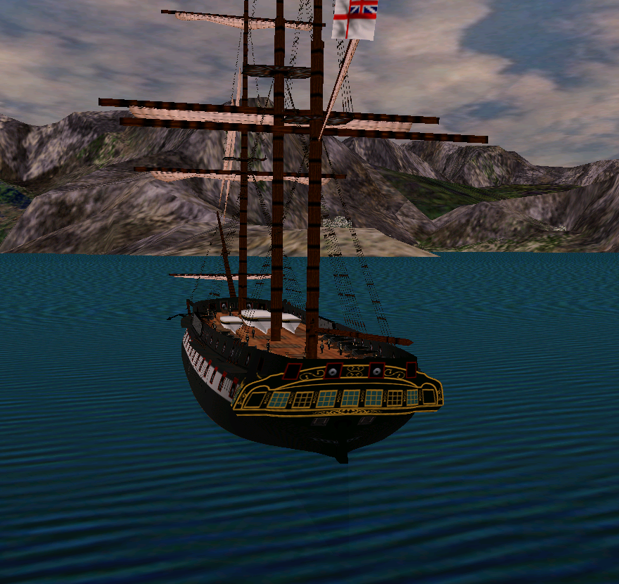
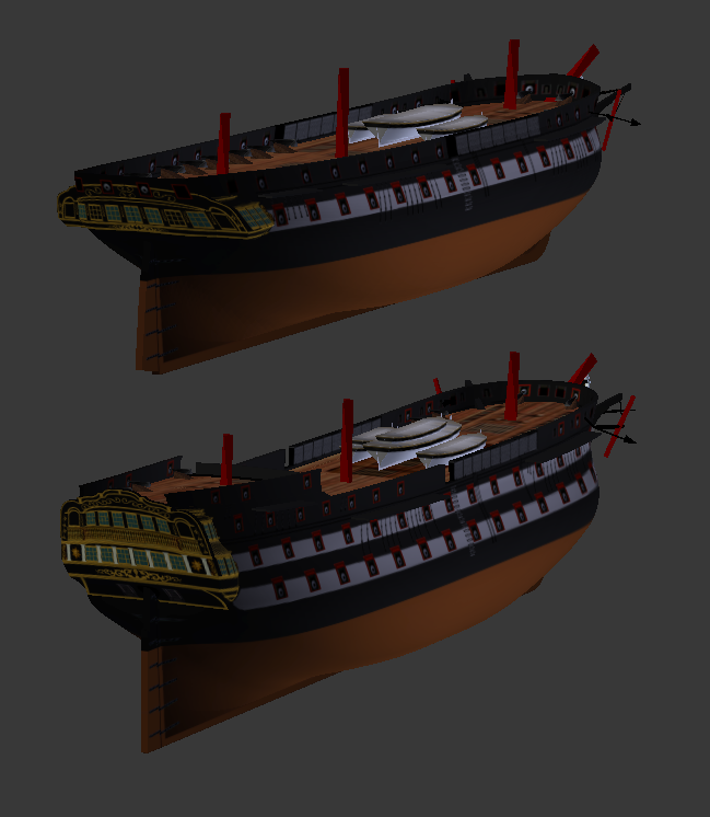
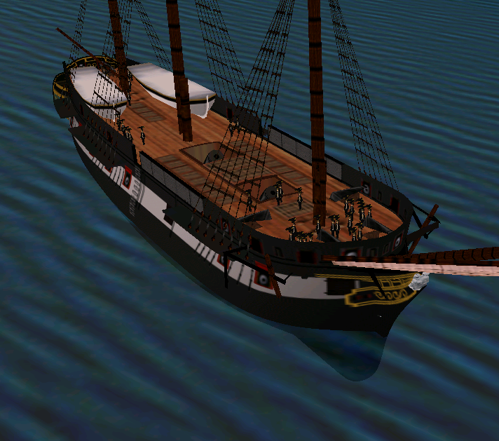
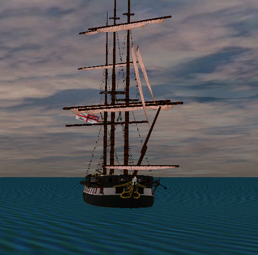
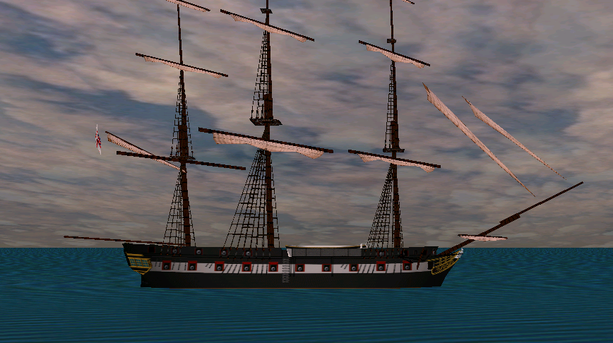
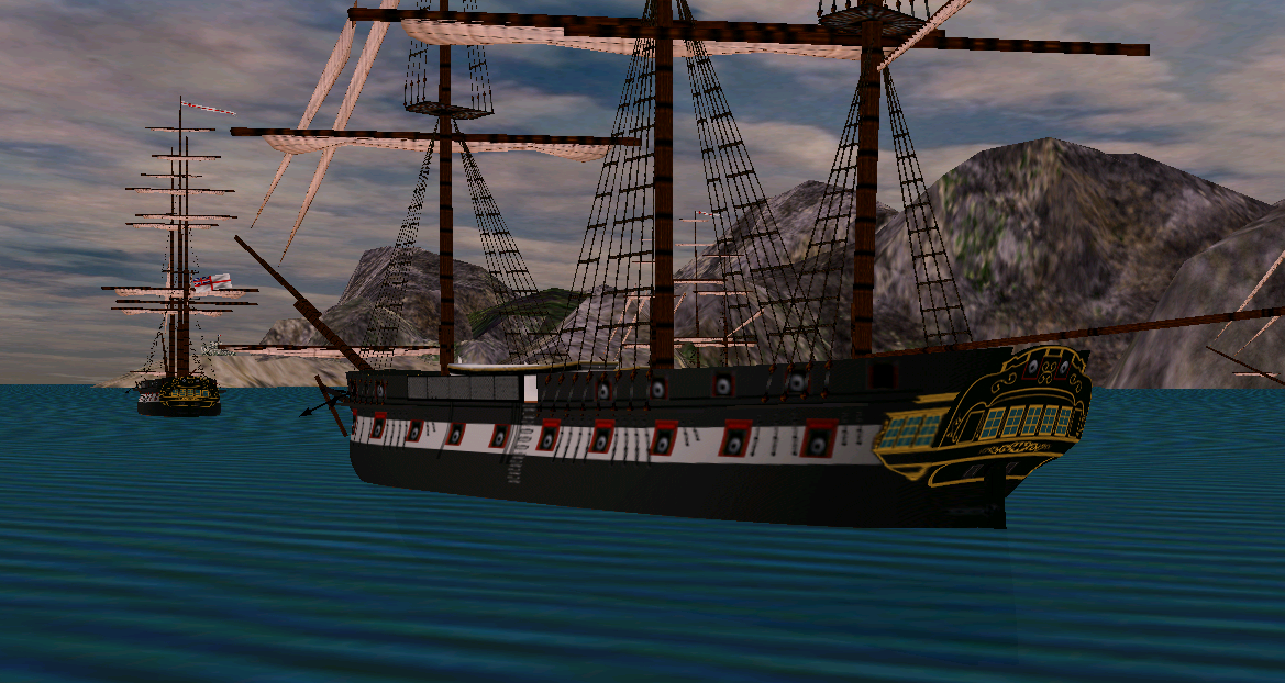
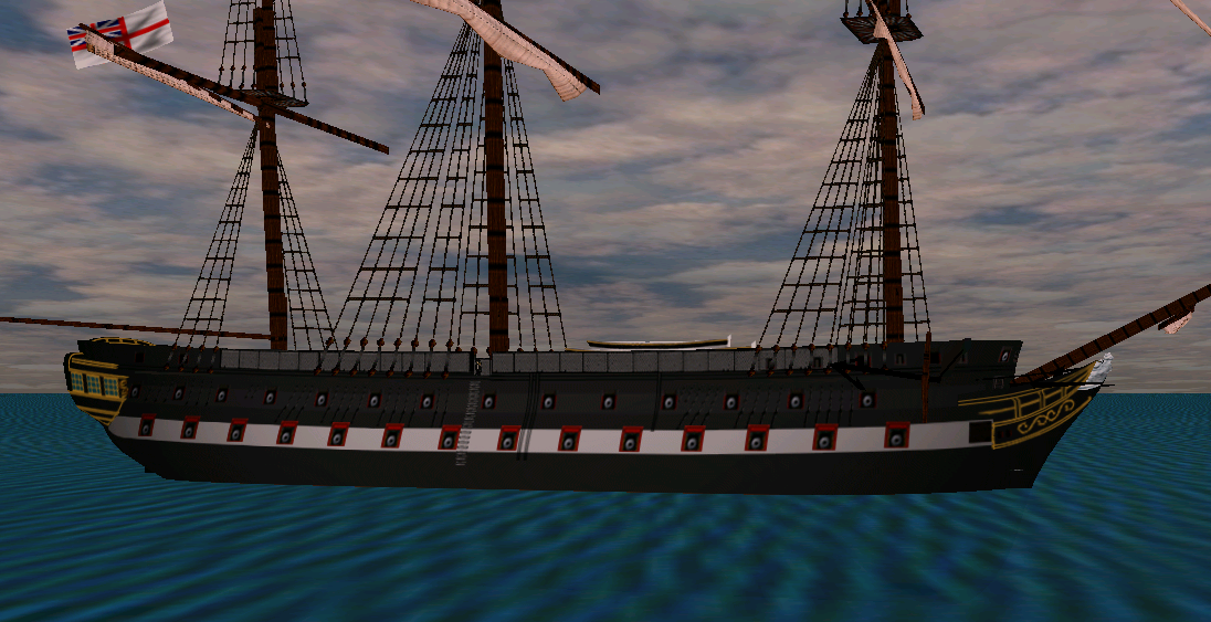
Reluctant as I am usually to post early images, allow me to present is my interpretation of the bomb vessel La Salamandre. She's still very much work in progress, and many details will are subject to change. The 998 (21 MG 32) model provided me with necessary justification of applying Napoleonic era style (which I, of course, intended to do anyway, but imagine my happiness when I discovered it was actually done by someone at that time!) and changes to the layout (flush decks, enclosed bow, solid bulwarks), and I intend to follow this model by replacing two fixed mortars with one rotating emplacement. She also differs from the book plan set in being based on the original Coulomb plan rather than on reconstructed one, for the main reason that the original plan was aligned to the waterline and I thought it would be much easier to use it than to make the model on even keel and then rotate it. My initial plan was to use rotated layout for the stern from the reconstructed set, but it turns out that - while it is certainly not the rule - in this particular case the decoration proposal for the ship fits the original plan very well, as if the designer was, in fact, familiar with the ship's plans and layout. This fit is even better than the reconstruction's, so I extended the purist approach and tried to apply the proposed stern design as is to the model. The difference is primarily in the height of the counters and arc of the taffrail. For the decorations (which are also far from finalized) I used elements from renderings of absolutely marvelous work by @Bernard Huc, with his kindest permission. When ready, the model will, probably, have at least three variants. First is the travel configuration, which you can see here. An installed foremast, the bomb well covered with deck and boats. The bombardment configuration will feature visible mortar and have the foremast and the boats removed, and finally a sloop configuration will be similar to the travel, but will instead have a full battery deck with 9 armed port pairs. All that, though, is still a long way off.
-
USF Confederacy in 3D | Blender
Martes replied to 3DShipWright's topic in CAD and 3D Modelling/Drafting Plans with Software
Which is a very plausible explanation :)- 107 replies
-
- Frigate
- Confederacy
-
(and 1 more)
Tagged with:
-
USF Confederacy in 3D | Blender
Martes replied to 3DShipWright's topic in CAD and 3D Modelling/Drafting Plans with Software
Thou shall not trust Hahn. But, seriously, he went so far with structure simplification, that it has nothing to do with how real ships were constructed. Only contemporary practices and examples (the same Constitution) can provide some clues to construction methods.- 107 replies
-
- Frigate
- Confederacy
-
(and 1 more)
Tagged with:
-
USF Confederacy in 3D | Blender
Martes replied to 3DShipWright's topic in CAD and 3D Modelling/Drafting Plans with Software
Note, thought, that the Constitution does have cant framing both fore and aft, as we discussed earlier. So if you employed cant frames forward on the Confederacy, you possibly should consider doing the same on the aft end... And how dense her framing is.- 107 replies
-
- Frigate
- Confederacy
-
(and 1 more)
Tagged with:
-
USF Confederacy in 3D | Blender
Martes replied to 3DShipWright's topic in CAD and 3D Modelling/Drafting Plans with Software
Exactly like it's neighbour to the right. You missed the diagonal estain - if I remember the name correctly - under it though. The transom pieces do not go into the vertical pair, but rather connected to it and supported by vertical frames from below (at least in French contemporary methods, without cant frames aft). Otherwise it is even more complicated- 107 replies
-
- Frigate
- Confederacy
-
(and 1 more)
Tagged with:
-
Indy is a popular ship, after all
-
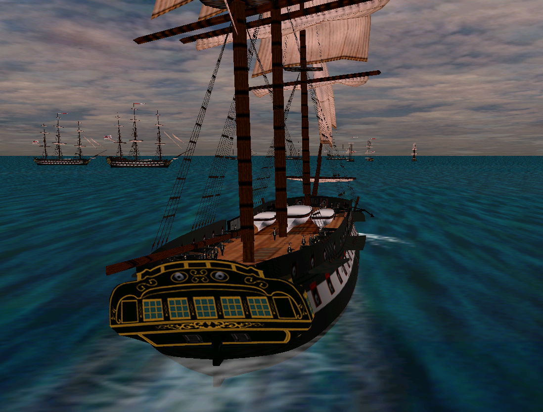
Most of the stern decorations are, in fact, renderings of 3d objects, including counter rails and window frames, and others are taken either from photos or plans and recolored. The only curves I draw by hand are the boundaries of the sternboard and the taffrail. Ironically, I replaced the glass texture with solid fill at some point, though, because it looked better at this resolution and was easier to reproduce on the hull texture, which is even more compressed - the sterns are usually 256 x 128 pixels for frigates or 256 x 256 for two-deckers, and the frigate hulls until very recently were only 512 x 256. I shifted to 1024 x 256 on the new 74 and razee series and since the game handles them well, will be updating at least the larger frigates gradually, but it all takes time.
-
@The Art of Age of Sail, I was looking for materials about the Indefatigable around 2017 and your reconstruction was almost the first I encountered then, so I clearly remember it. I think the model in Naval Action/Ultimate Admiral computer games is also based on your project.
-
The kit appears to be based on a reconstruction that had been around since at least in 2017, when I found it, probably done even earlier.
-
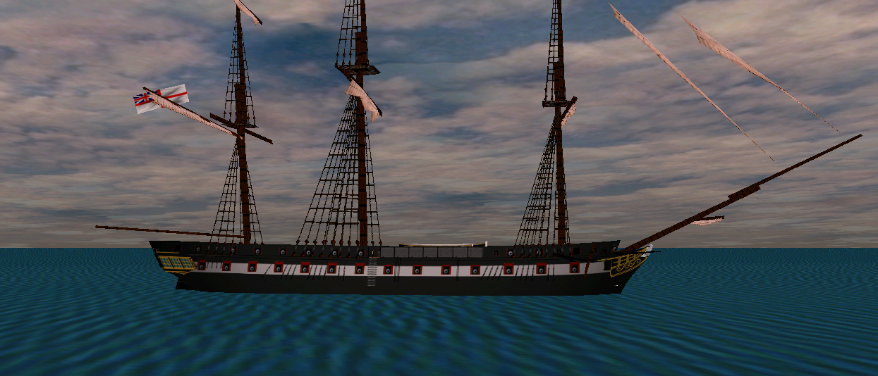
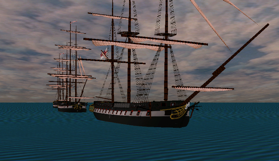
Now that I have a razee-74 short, I did a razee-74 stretch: The 180 ft hull fitted with Symonds-style elliptical stern with classic quarter galleries and elegantly raked aft, based on the plans of the Warspite rebuild of 1840. The texture is not completely finalized and polished at places (you will probably notice that some details are still missing or not completely fitted), but the model already conveys the appearance of the ship.
-
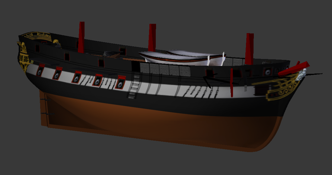
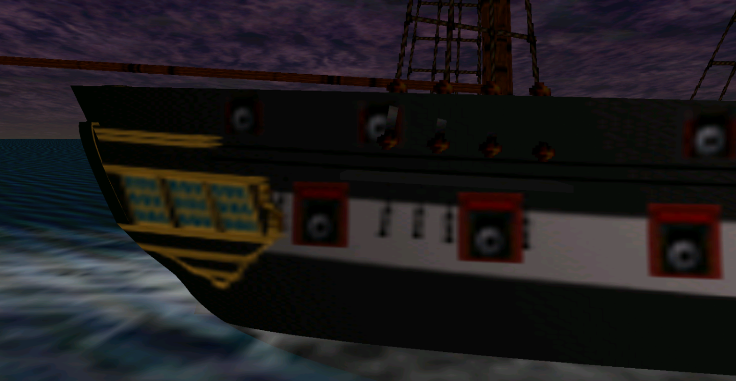
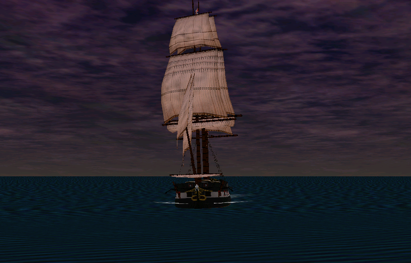
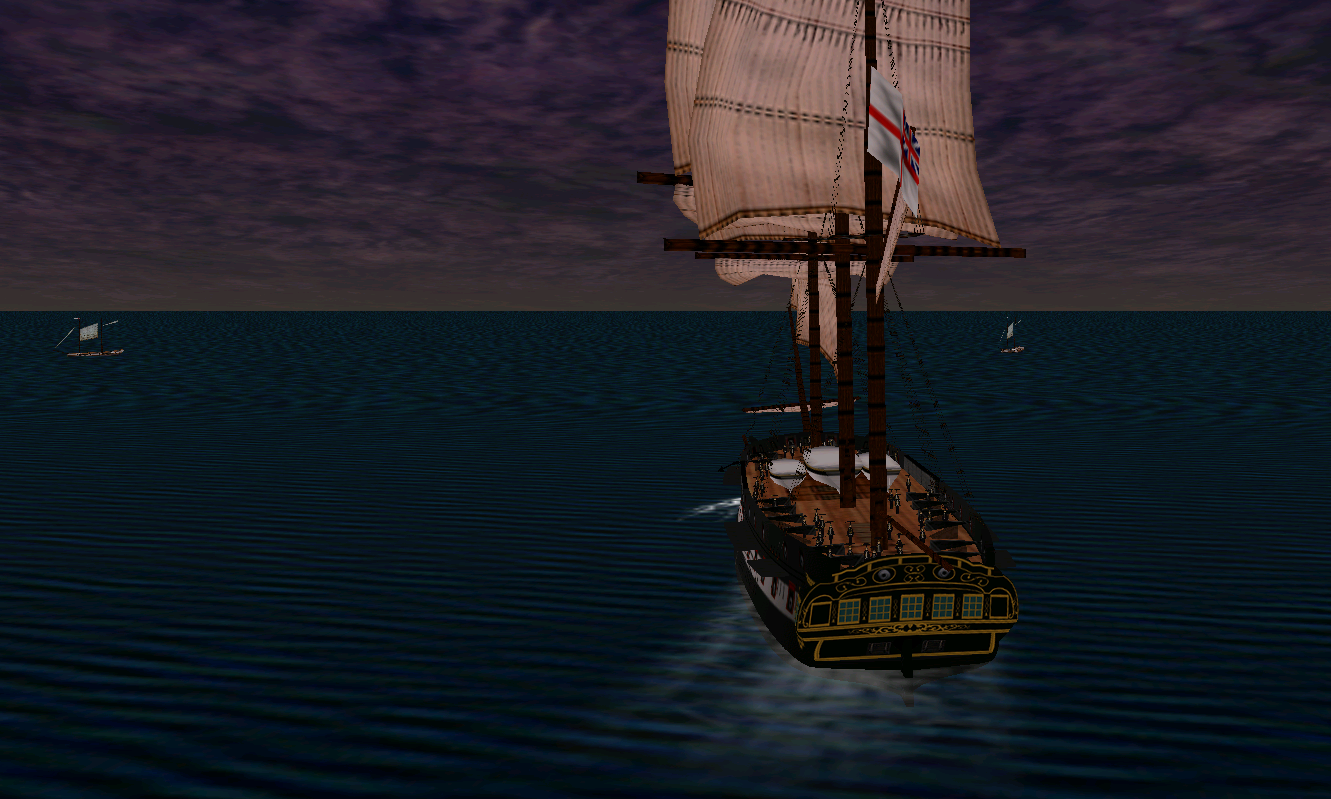
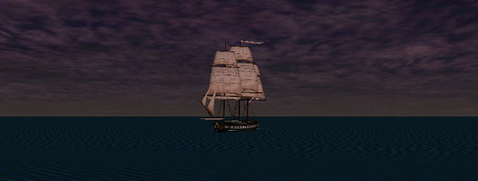
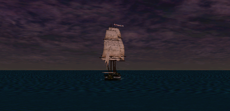
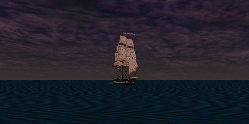
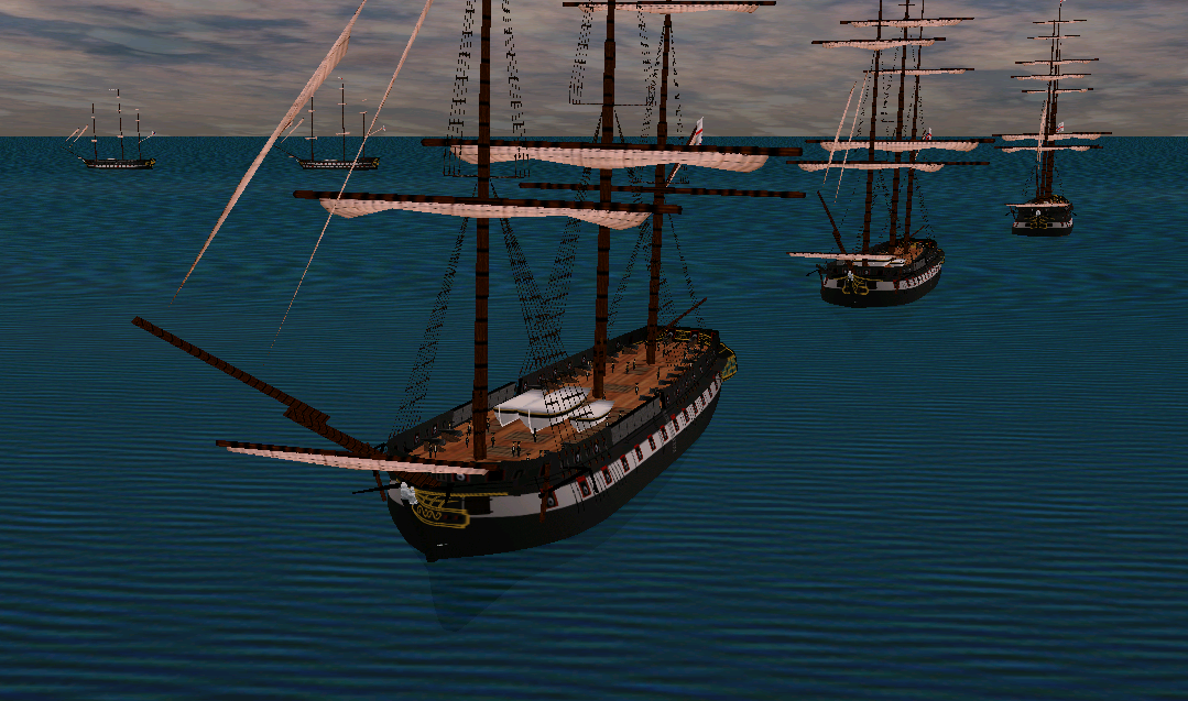
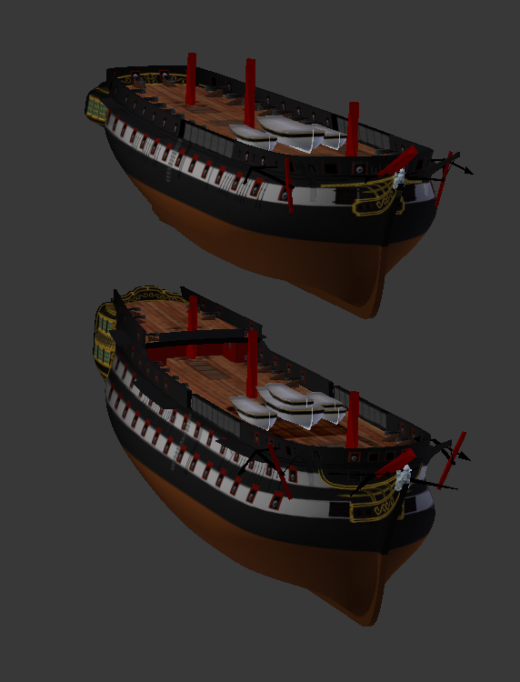
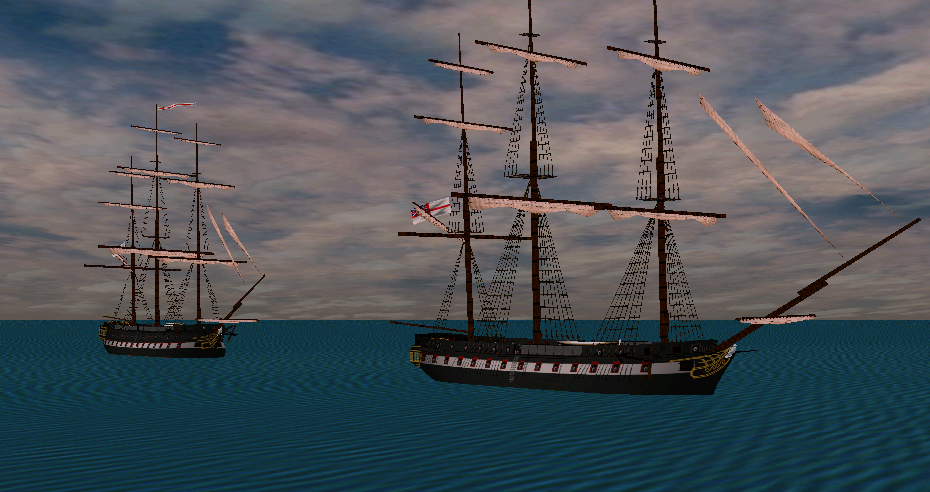
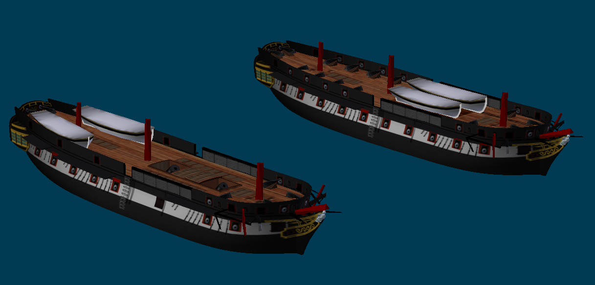
It took several additional iterations to get the head rails angles right and in the same style as other models, and finally the small ships are ready: The bomb vessel And the corvette At the same time, I changed the shading of the upper deck gunports on the two-decker razee: and shifted the first armed gun port on the frigate variant slightly forward: The last one was a difficult decision, since some ships had the port shifted from it's original position on the 74 and some hadn't. But it just looks better.
About us
Modelshipworld - Advancing Ship Modeling through Research
SSL Secured
Your security is important for us so this Website is SSL-Secured
NRG Mailing Address
Nautical Research Guild
237 South Lincoln Street
Westmont IL, 60559-1917
Model Ship World ® and the MSW logo are Registered Trademarks, and belong to the Nautical Research Guild (United States Patent and Trademark Office: No. 6,929,264 & No. 6,929,274, registered Dec. 20, 2022)
Helpful Links
About the NRG
If you enjoy building ship models that are historically accurate as well as beautiful, then The Nautical Research Guild (NRG) is just right for you.
The Guild is a non-profit educational organization whose mission is to “Advance Ship Modeling Through Research”. We provide support to our members in their efforts to raise the quality of their model ships.
The Nautical Research Guild has published our world-renowned quarterly magazine, The Nautical Research Journal, since 1955. The pages of the Journal are full of articles by accomplished ship modelers who show you how they create those exquisite details on their models, and by maritime historians who show you the correct details to build. The Journal is available in both print and digital editions. Go to the NRG web site (www.thenrg.org) to download a complimentary digital copy of the Journal. The NRG also publishes plan sets, books and compilations of back issues of the Journal and the former Ships in Scale and Model Ship Builder magazines.


