Martes
-
Posts
984 -
Joined
Content Type
Profiles
Forums
Gallery
Events
Everything posted by Martes
-
The state of the French Navy, July 1st, 1691
Martes replied to Martes's topic in Nautical/Naval History
I wonder what Gerard would say. -
Orders issued by the Duke of York 1661–1668
Martes replied to Waldemar's topic in Nautical/Naval History
Browsing the same folder, I saw two very interesting documents relating to Sweden (naval articles and a general report on the country) and a book on French naval signals (all for 1690s), but they are written in more elaborate and dense font and are slightly more difficult to read. -
Orders issued by the Duke of York 1661–1668
Martes replied to Waldemar's topic in Nautical/Naval History
Done! https://modelshipworld.com/topic/33925-the-state-of-the-french-navy-july-1st-1691/ -
The state of the French Navy, July 1st, 1691 Another absolutely incredible document, listing all the ships, the organization and the officers of the French Navy down to midshipmen. Written in Russian, but otherwise very easily readable.
-
Orders issued by the Duke of York 1661–1668
Martes replied to Waldemar's topic in Nautical/Naval History
Album of drawings of cannons and mortars Mostly mortars, but I spotted at least one naval gun -
Orders issued by the Duke of York 1661–1668
Martes replied to Waldemar's topic in Nautical/Naval History
The state of the French Navy, July 1st, 1691 Another absolutely incredible document, listing all the ships, the organization and the officers of the French Navy down to midshipmen. Written in Russian, but otherwise very easily readable. -
Orders issued by the Duke of York 1661–1668
Martes replied to Waldemar's topic in Nautical/Naval History
What a find! The language is very official and lively at the same time. I wonder if he really spoke like that. -
Stem posts, hm.
-
I have posted some here: https://modelshipworld.com/topic/29046-plans-from-russian-state-historical-museum/ https://modelshipworld.com/topic/24626-plans-found-in-hermitage-collection-st-petersburg/ There is a lot to do with identification of many of those plans.
-
The document may have been brought to Russia in 1695. Absolutely fantastic find.
-
3D Brig 'Rose' in Blender 3.3x
Martes replied to 3DShipWright's topic in CAD and 3D Modelling/Drafting Plans with Software
Convenient to fix a towing cable for example. Or pass two cables in parallel. It's something that usually gets lost now, but operating a sailing ship (and especially sailing warship at the time) reminds this old game more than anything else About the gunports. I meant to say, they should have a cant so you can - potentially - fix the lids there and the lids would not fall into the port.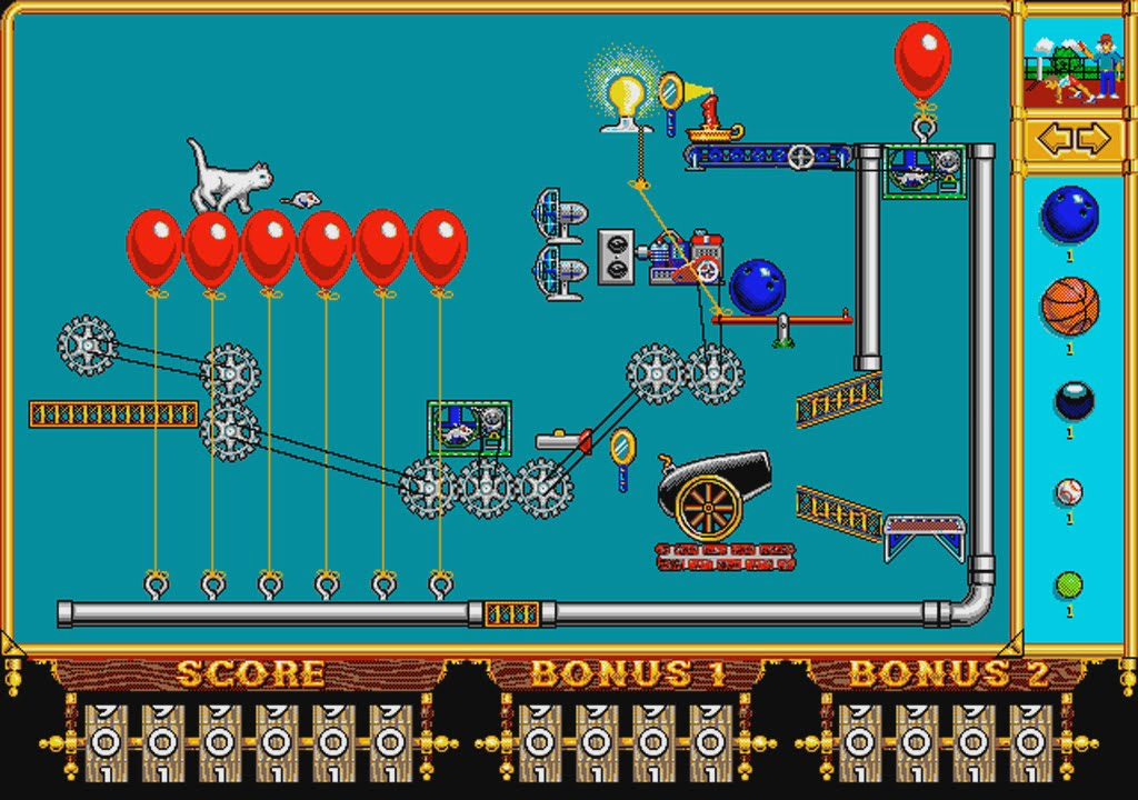
-
2nd rate London 1656 – the art of the shipwright
Martes replied to Waldemar's topic in Nautical/Naval History
The second variant of the line of breadth aft looks more natural, I'd say. And corresponding to the forward part. -
2nd rate London 1656 – the art of the shipwright
Martes replied to Waldemar's topic in Nautical/Naval History
Ships belonging to some periods may be considered more handsome than others, although it ultimately would be a function of personal preference. However, there is something in the English architecture of precisely mid-17th century, a style that disappeared afterwards. At least I fell in love with this model the moment I saw it's photos.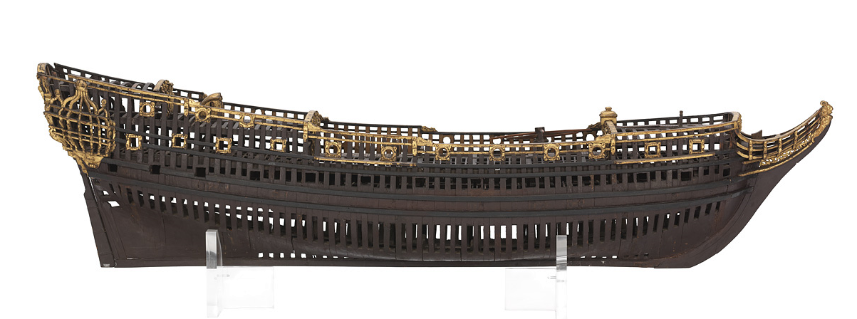
-
2nd rate London 1656 – the art of the shipwright
Martes replied to Waldemar's topic in Nautical/Naval History
She gets incredibly lovely. -
3D Brig 'Rose' in Blender 3.3x
Martes replied to 3DShipWright's topic in CAD and 3D Modelling/Drafting Plans with Software
I meant lids on the stern ports. The side ports would usually have no lids, as they are useful for draining excess water, same as on ships of other classes that did not have lids on most of the upper deck ports. Later, circa 1820-30 style would introduce half-ports to brigs, but that's really later, and usually lower halfs. And curiously enough they opened up and were, I assume, removable: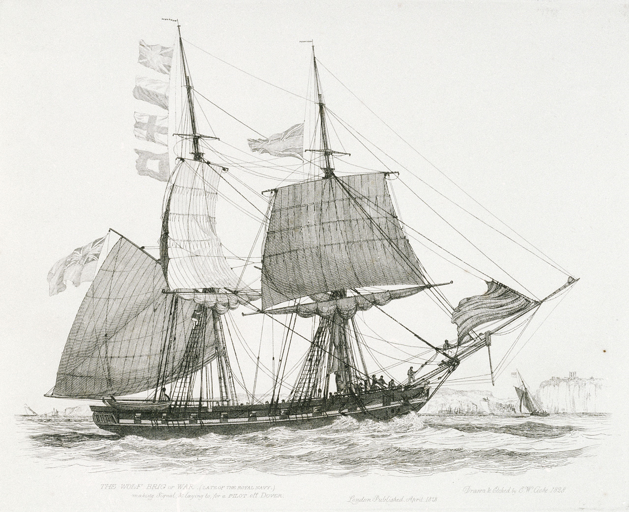
-
3D Brig 'Rose' in Blender 3.3x
Martes replied to 3DShipWright's topic in CAD and 3D Modelling/Drafting Plans with Software
https://modelshipworld.com/topic/33641-location-of-bell-on-a-cutter/ for some ideas. Probably some makeshift stand forward, or, if you would go for a flying forecastle, between it's supports. Nothing more concrete at the moment. -
3D Brig 'Rose' in Blender 3.3x
Martes replied to 3DShipWright's topic in CAD and 3D Modelling/Drafting Plans with Software
I only said it should be verified to be possible. The chase guns on the brig were usually 9-pounders (although there were cases of long 24s (!) fitted). They were, by default, mounted at the bow, but not at chase positions. There was a long, international discussion about how the poop and the flying forecastle obstruct the use of chase guns, providing very little head room, etc., but on the other hand they were useful for sail tending and provided some degree of protection from weather, which was kind of critical in long commissions. This discussion went well into 1840's and ended with the end of the age of sail practically. Anyway, the sailing ship is not a fixed structure, and if there was a real need to fire astern, a way could be found. So if you needed to really, really fire astern, you could remove the deckhouse partitions (they should have been removed anyway when the ship went to quarters, but just in case), unship the tiller, pass the control of the rudder to those chains via ropes overside (this works for the situation), bring the gun from the front of the ship, and fire. It is unlikely that you can position both guns there and fire (and reload) them both, but that would depend on how desperate the situation is, I guess. And then, if it works out, get everything back. Another thing is that the ports should be able to be closed. I am not sure there were permanent lids fitted (most likely not), but, again, there is a number of situations when you could want them to be shut with something. She still rides very high, as if underloaded -
Look between gunports 2 and 3 down. You also can give some more curve and volume to the quarter galleries, they look somewhat flatter than they should be. Everything else looks more or less plausible. The difference between 4th rate and 3rd is in size and number of gunports, architecturally they are practically identical (unless you go for a flush-deck version of a 44). Frigates were in the 5th rate There are a lot of high-res plans at wikimedia commons.
-
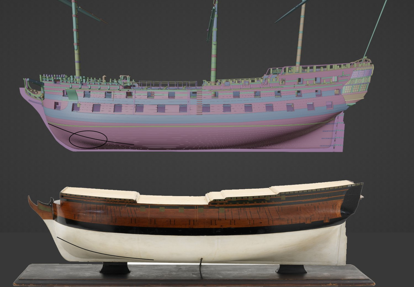
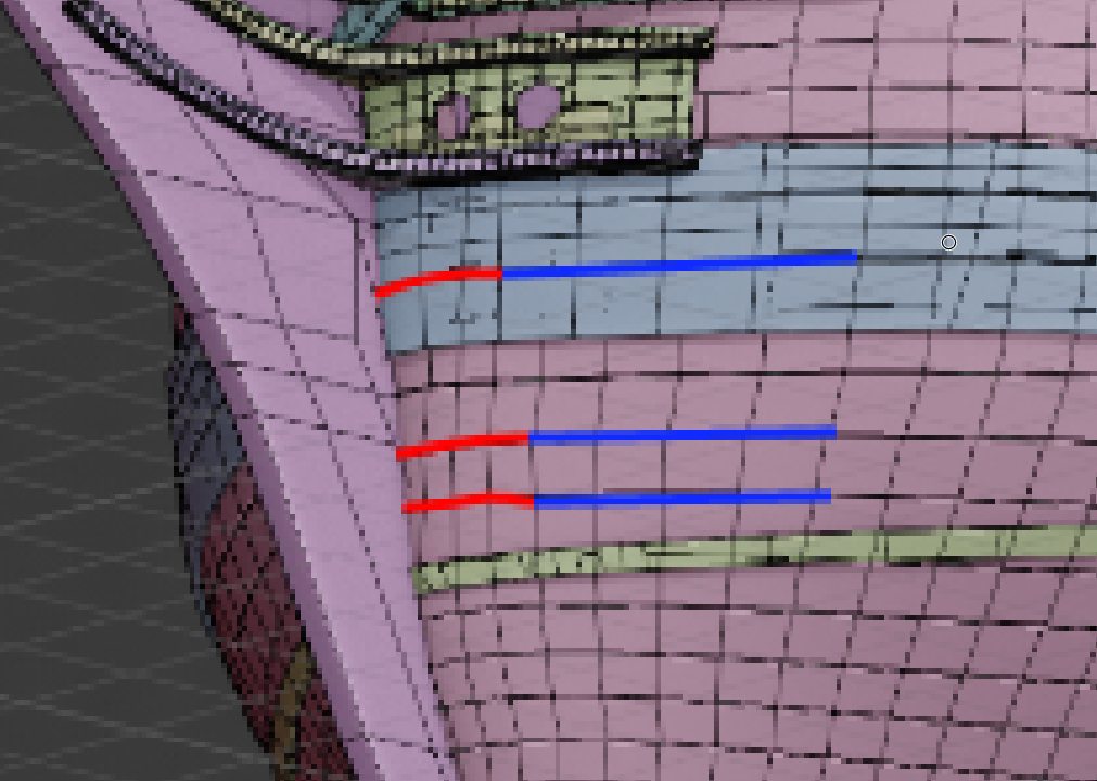
A small clarification of what I meant. If the blue line goes towards the keel at a certain angle, the red should not curve outwards. It should be either straightly tangent to the last segment of the blue, or even slightly concave, if in the lower part of the hull, and it's rather the blue segment should be slightly curved to ensure the red hits the intersection with the keel.
-
2nd rate London 1656 – the art of the shipwright
Martes replied to Waldemar's topic in Nautical/Naval History
I may be mistaken, but - purely visually - doesn't the transition around M appear to slightly distort the surface? -
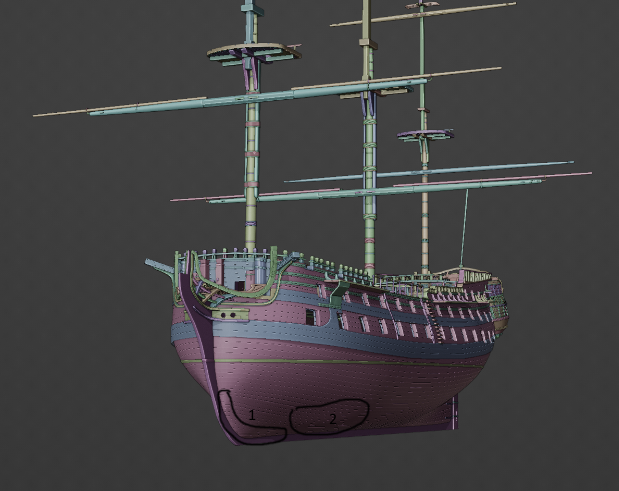
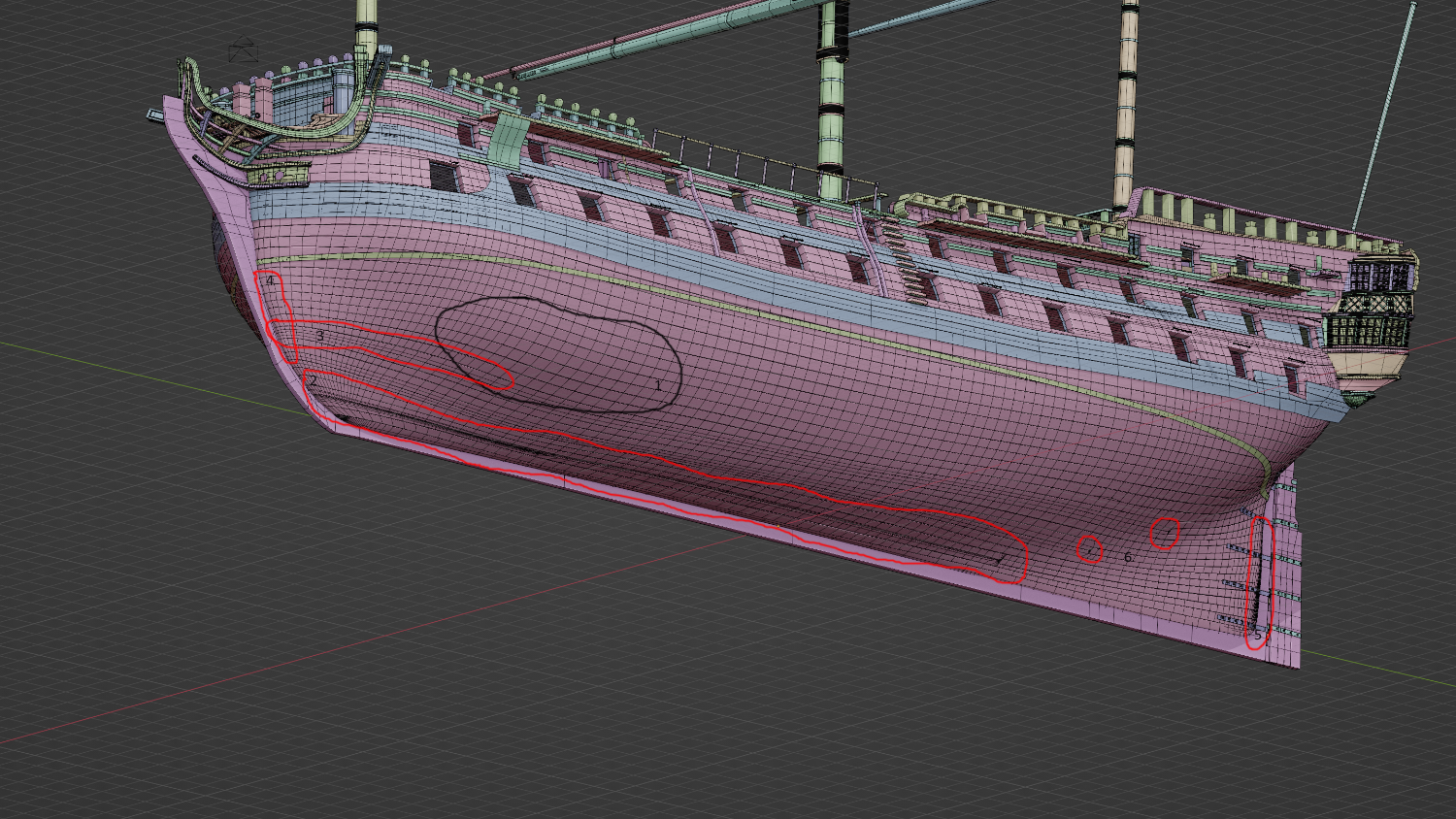
First of all, there is a bulge in region 1. Then, try to get rid of the enormous amount of redundant vertices in 2, 3, 5 and 6 - such regions usually cause terrible headache for smoothing algorithms. Finally, try to make the segments in 4 (and up to the hawseholes) straight on approach to the keel. If done correctly, the shading should appear more or less similar to the model Of course, it's all reverse-engineering, and at certain stage it could be simpler to actually redraw the hull mesh from the plan. But I will not go as far as to recommend it

-
2nd rate London 1656 – the art of the shipwright
Martes replied to Waldemar's topic in Nautical/Naval History
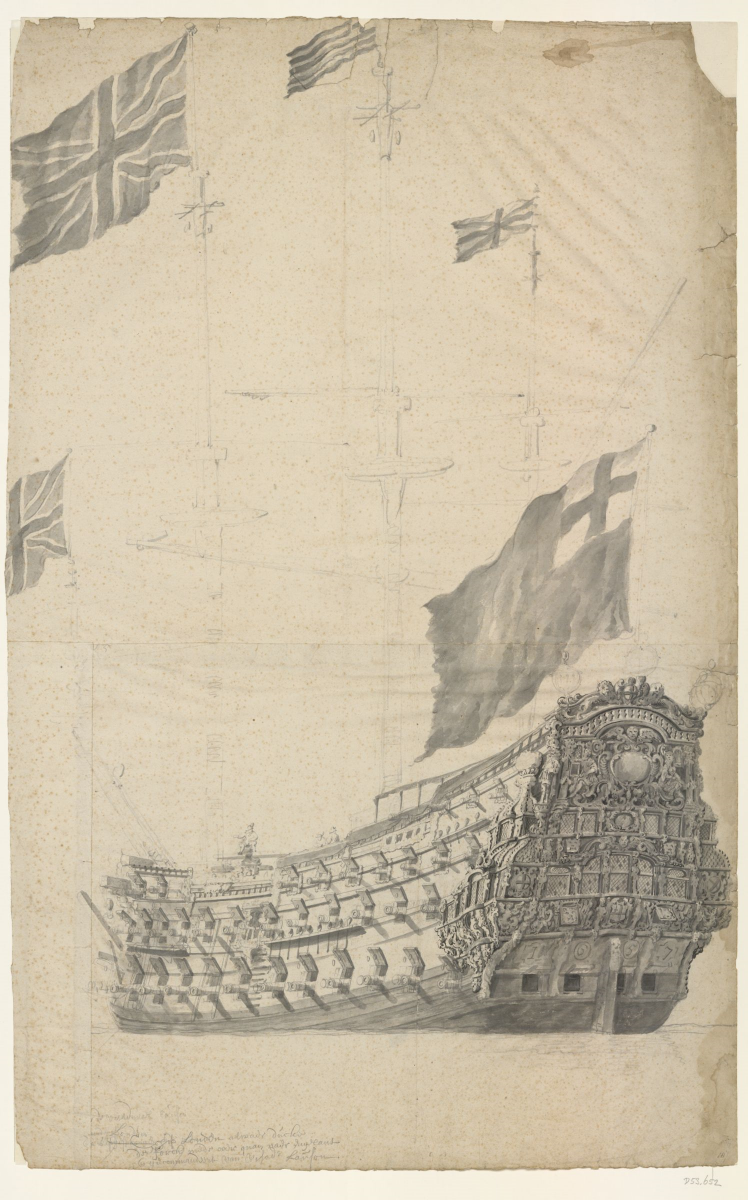
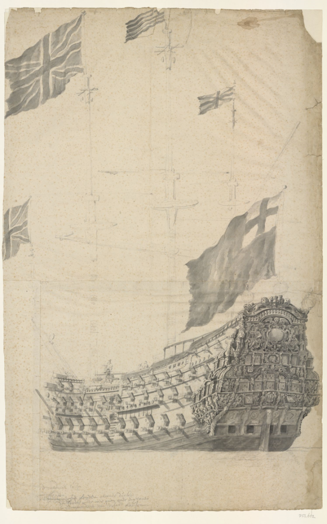
I thought of peculiar nature of industrial espionage in this case. Usually one would think that to steal a design of a ship, a whole lot of documentation must be obtained and transported. But in this case the required information would fit on a scrap of paper or could be just memorized. You just have to have somebody who knows what to do with them There are 2 portraits of the ship by Van de Velde, one mentioned above by @allanyed: https://www.rmg.co.uk/collections/objects/rmgc-object-136130 And another in a Dutch collection (visit the site for full size, the cat faces on the gunport lids are quite adorable): http://collectie.atlasvanstolk.nl/data_nl.asp?q0=85301&startc=1&subj=27&bron=theslijst The stern decorations on the second drawing are somewhat different those on the plan, and they are probably Commonwealth era.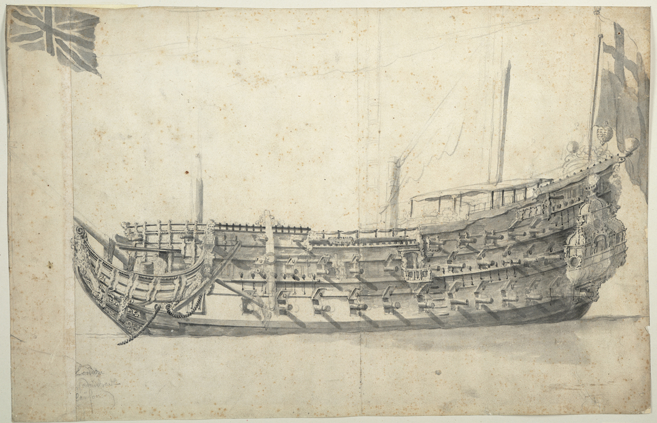
-
2nd rate London 1656 – the art of the shipwright
Martes replied to Waldemar's topic in Nautical/Naval History
What especially astonishes me here is level of data compression. With these methods, how much numbers you have to memorize to correctly unpack the ship plan afterwards? -
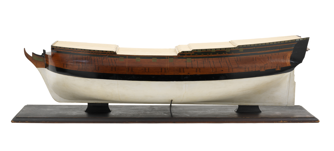
It more or less should be pinched at the entry. I am not even sure if it's enough (1), the surface should not be convex here, either straight or pinched slightly. Check against the model. https://www.rmg.co.uk/collections/objects/rmgc-object-66465 (and the hull lines on the plan) If you could show me the wireframe, I probably could pinpoint how to fix this (2): Shadow should not fork this way, it indicates some problem with the run of the hull. The roundhouses are ok.
-
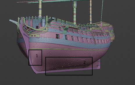
Almost! Make them more tangent to the keel at region 1 and smooth out the curve in 2, and it will be all right. As to the roundhouse, I'd simply scale it up somewhat.