HOLIDAY DONATION DRIVE - SUPPORT MSW - DO YOUR PART TO KEEP THIS GREAT FORUM GOING! (Only 75 donations so far out of 49,000 members - C'mon guys!)
×

Steve Harvath
-
Posts
65 -
Joined
-
Last visited
Content Type
Profiles
Forums
Gallery
Events
Everything posted by Steve Harvath
-
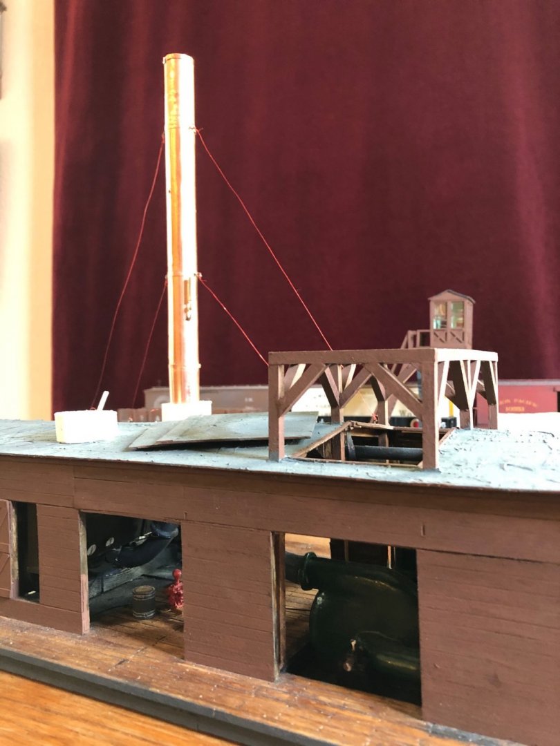
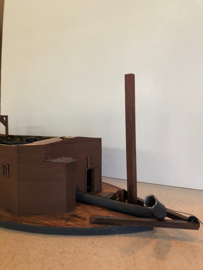
John, Yes, the from the plan the chimney stacks scale out at 37 feet above the roof. To me it kind of looks like a classic mid-America stern wheel river boat.
-
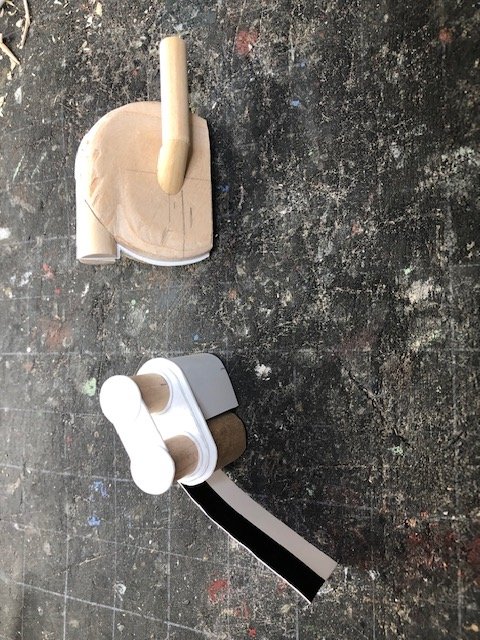
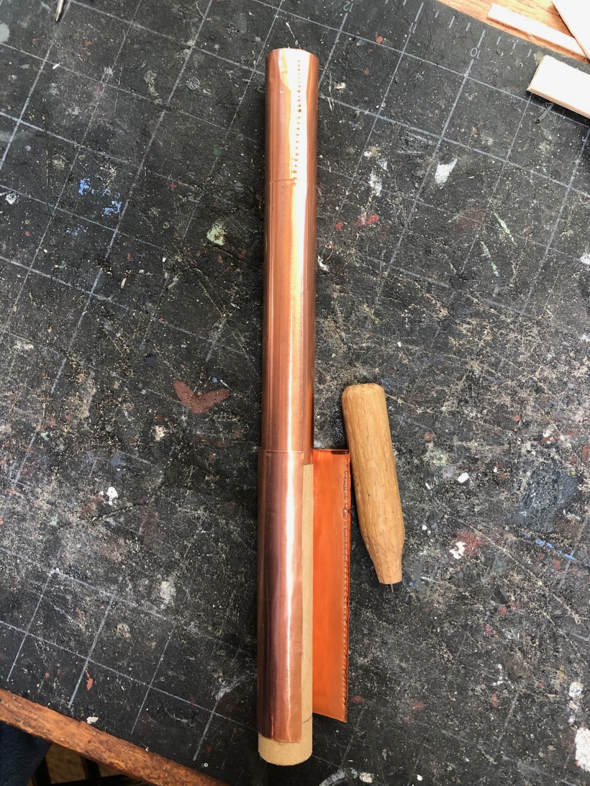
I have been constructing and installing the stacks. I found a wooden dowel that was close the correct scale diameter -- 41 inches. I sheathed the dowels with copper foil and simulated rivets with my home-made riveting tool (a dulled needle in a stick handle - patent pending).

-
Thank you
-
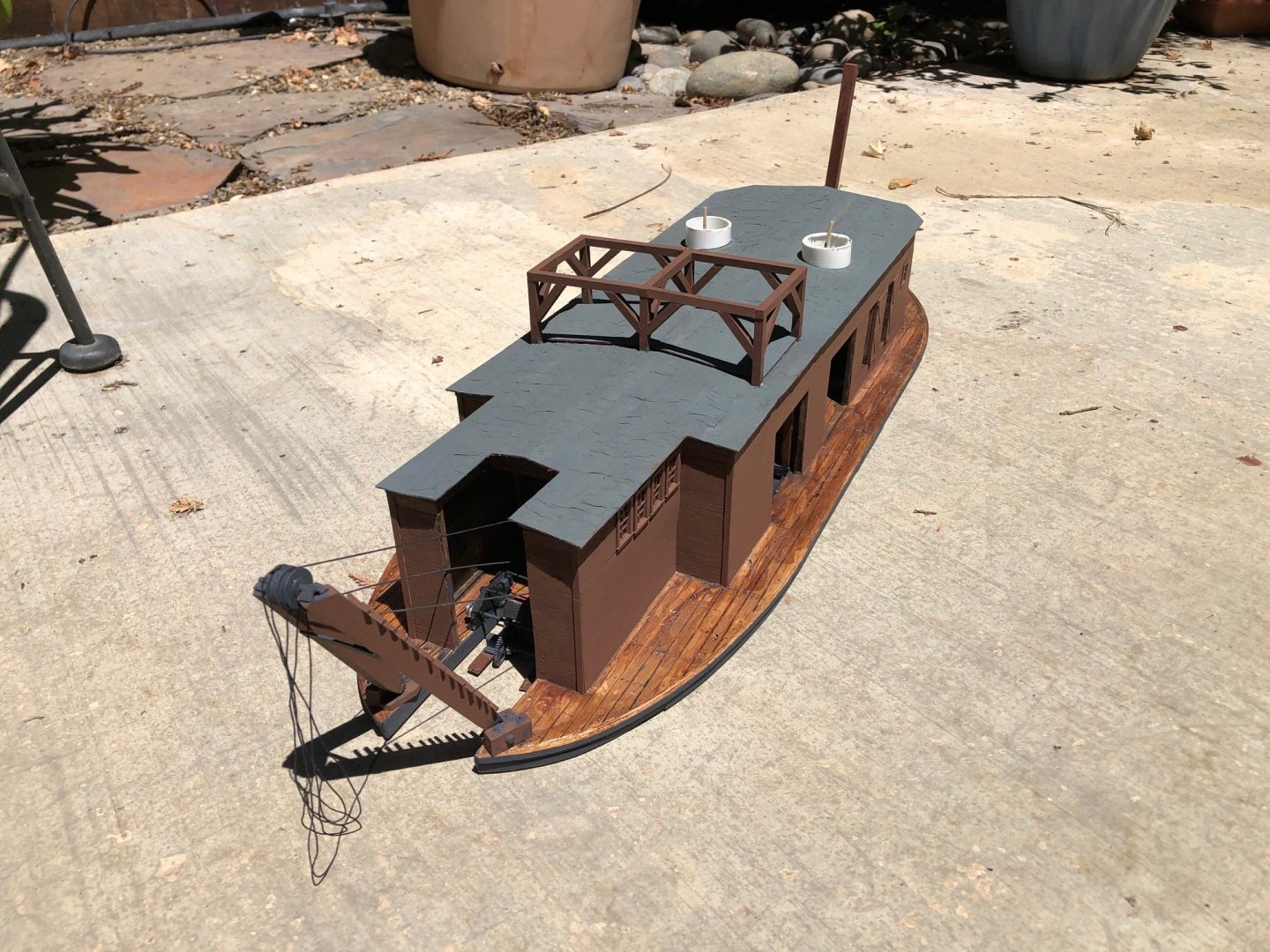
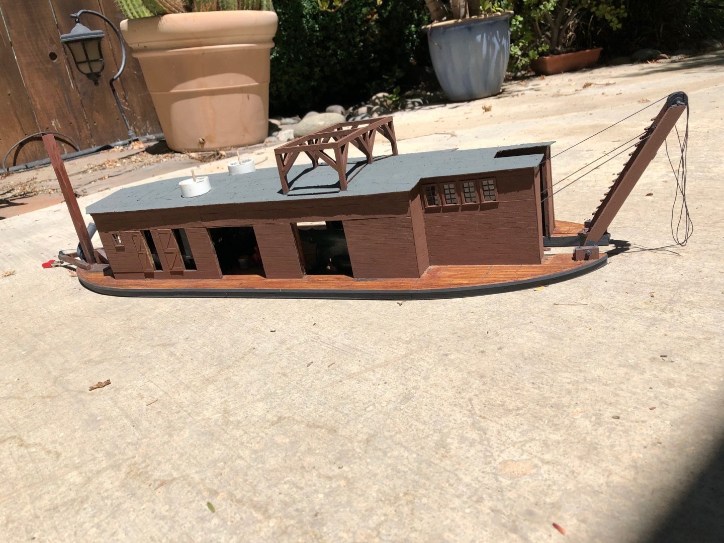
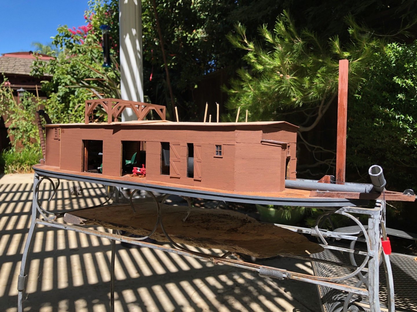
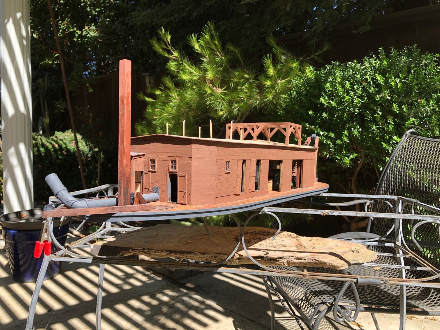
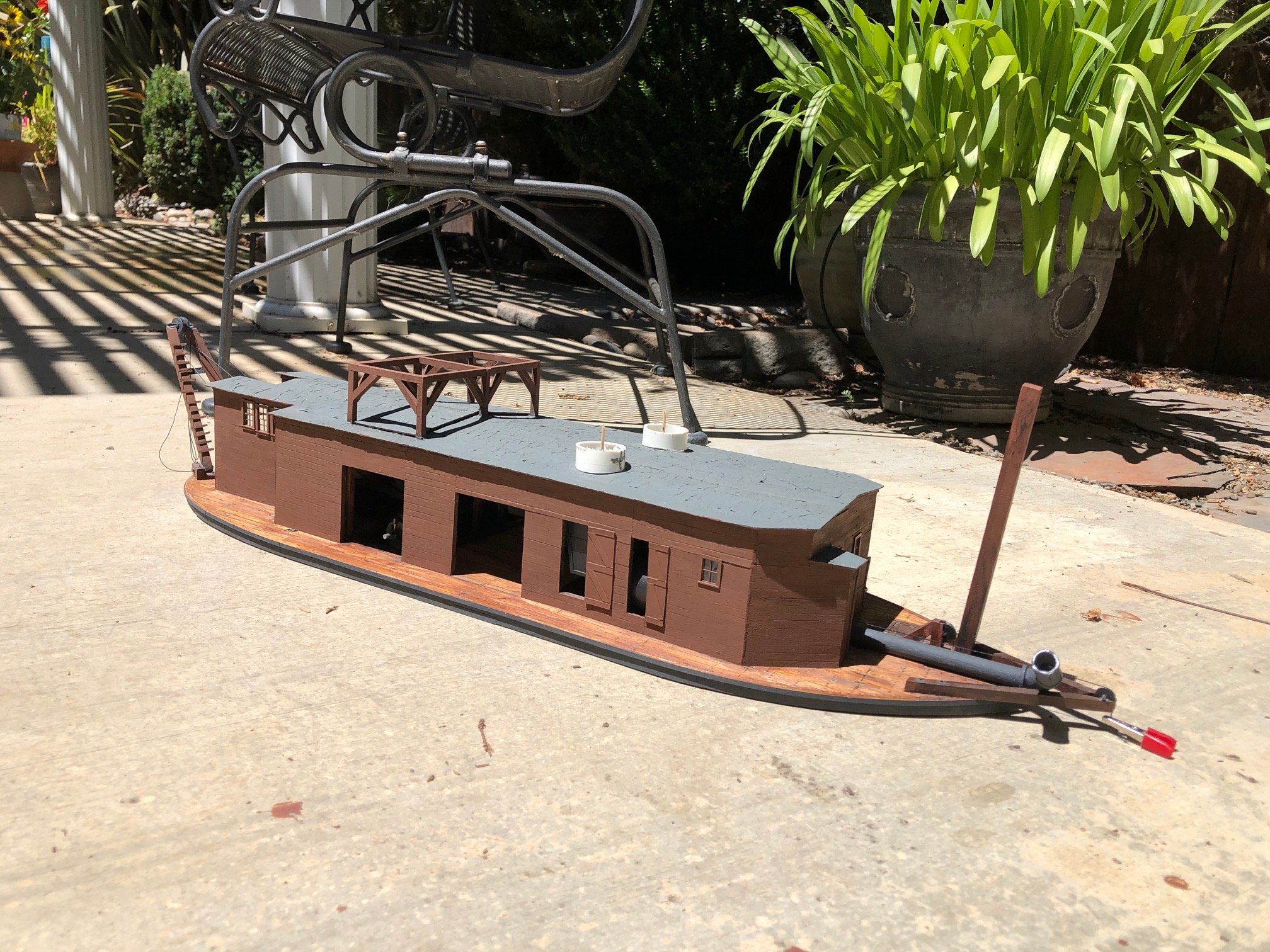
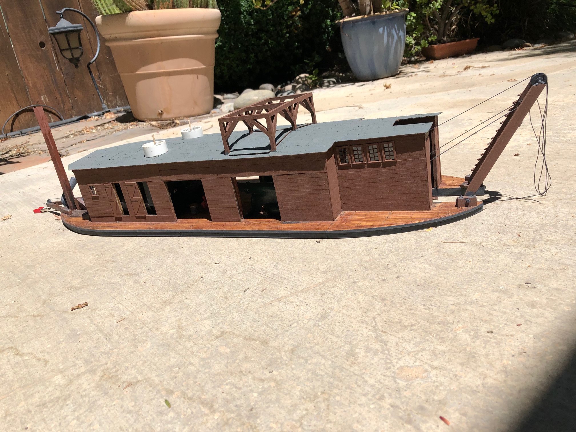
I have applied the roofing to the deck house. In keeping with the rough hewn industrial nature of the dredge I simulated rolled roofing with that rare commodity -- toilet paper. I cut it into strips a scale three feet wide and applied it with a gray paint. It came out like it was kind of bubbling up and warping in the heat and humidity. Here re some images with the roof hatches on and off. I also found some plastic tubing that is a good diameter to represent the wider base portion of stacks. There must be a name for these. They insulate the roof from direct contact with the flammable roof.


-
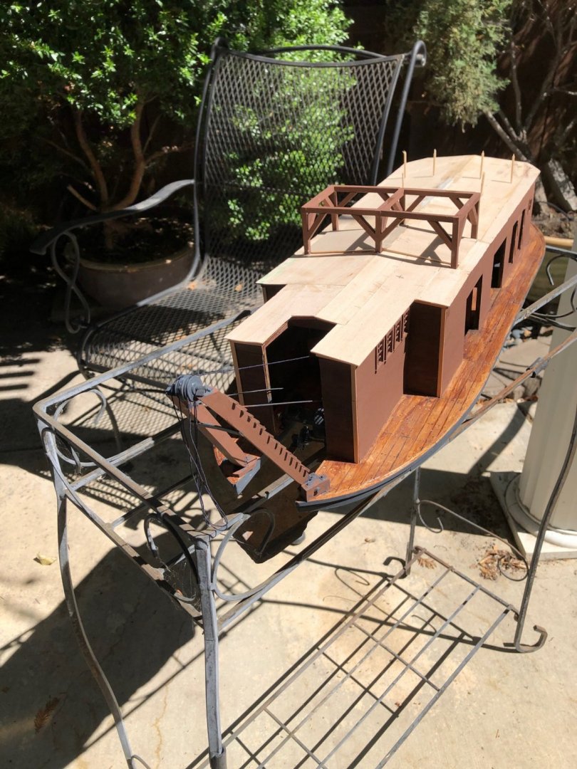
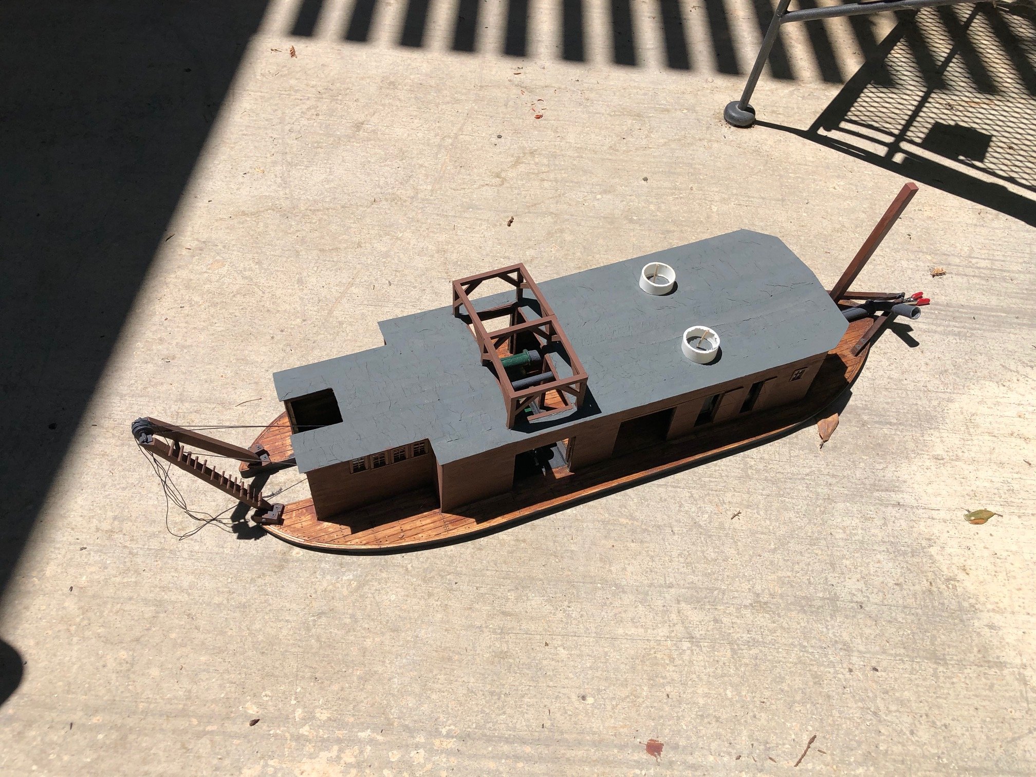
I have finished roofing the deck house and applying trim under the eaves and at right angle corners. I decided to model roof hatches over the pumping equipment bay. I think you can see the edge of a roof hatch in the image of the as-built dredge. My thought has been that the heavy duty scaffolding above the roof was used to service the equipment below with chain lifts. I made the roof hatches removable so it is easier to view the interior. Doing touch up painting as I go.
.thumb.jpg.9e54a5452ed20b4ca4292ec871c27a3e.jpg)


.thumb.jpg.f3b535b8058e042512f856089cebc5d7.jpg)
-
Mississippi Sternwheeler by kpnuts
Steve Harvath replied to kpnuts's topic in - Build logs for subjects built 1851 - 1900
Very nice stern wheel project. I have to put twin stacks like that on my hydraulic dredge. How did you build them? -
Hello from the San Francisco Bay Area
Steve Harvath replied to ChuckJ's topic in New member Introductions
The stern has the letters E and R which might stand for Elizabeth Regina -- Queen Elizabeth I of England. But the symbol between the letters looks like a fleur de leis which would be French. Probably just made up. -
I have been finishing the installation of the dredge equipment, installing windows and painting the deck house. Next on to the roof of the deck house and stacks.


- 69 replies
-
- 11
-

-
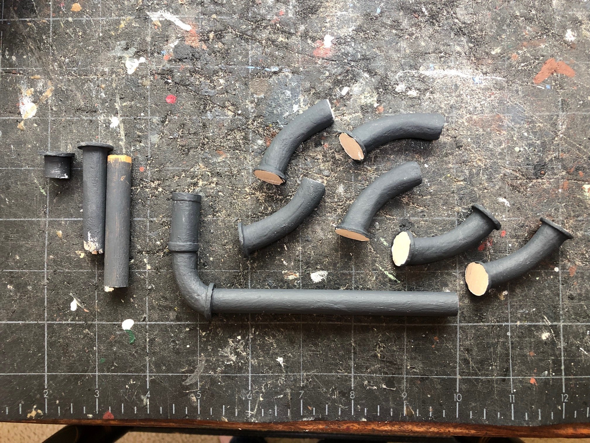
Wefalck, That worked great. Much more realistic looking gears. I have been working on how to model the large diameter pipe used for the suction line. On the plan it specifies an 18" inside diameter pipe. When I looked at the plan closely I realized that there were six identical flanged pipe sections represented in the line. By my measurement each section is one sixth of a circle or a 60 degree section of a circle. I think it was made without right angle elbows to facilitate the flow of the sludge. I thought these might be cast iron with flanges that bolted together. I made a ply of basswood and balsa wood that is scale 20" thick and carved and sanded out the sections. I put some filler in against the flange to smooth out the corners and make them look more like castings. I gessoed them and painted them a graphite color.
.thumb.jpg.bce42f8bcfe1e823ace398c0be3654aa.jpg)
.thumb.jpg.76001dd3af0900e98b31b41bae21fbe8.jpg)

-
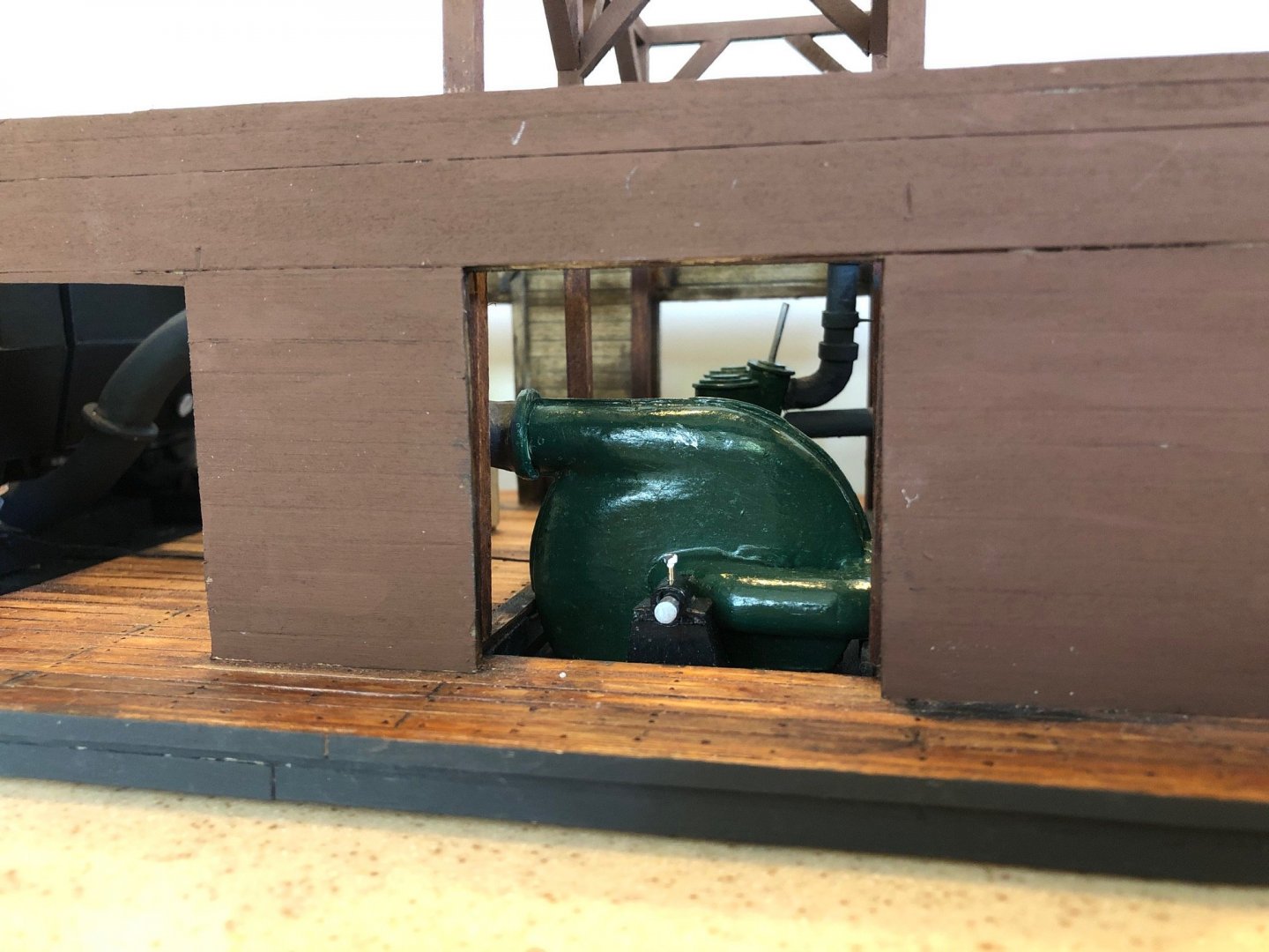
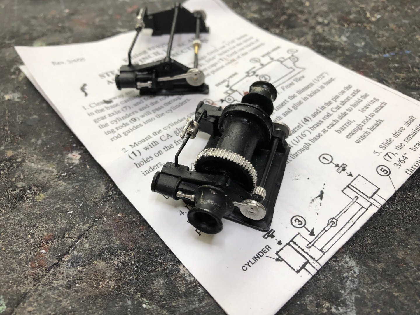
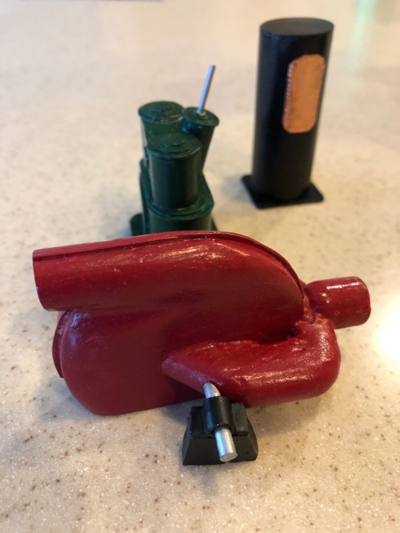
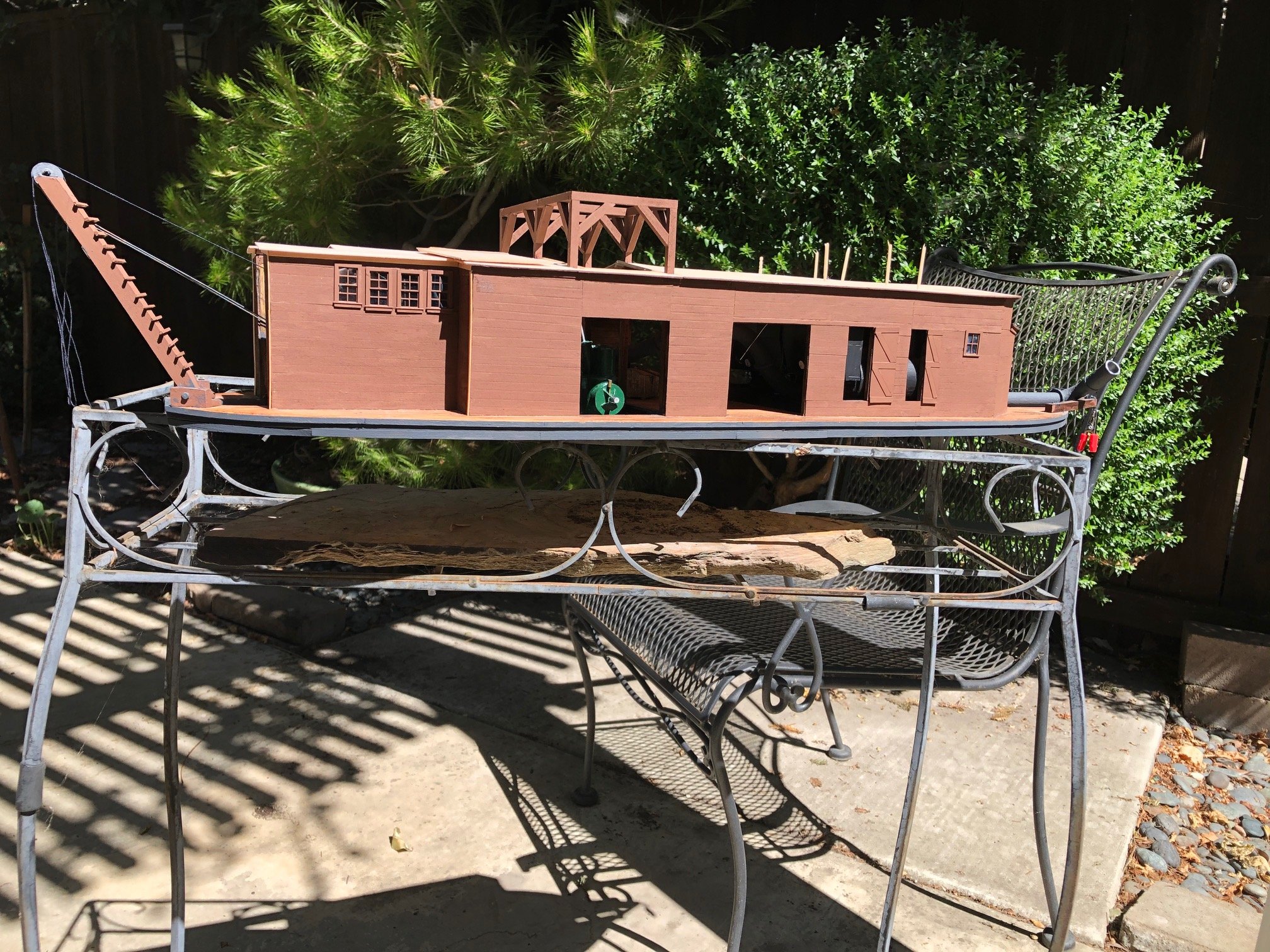
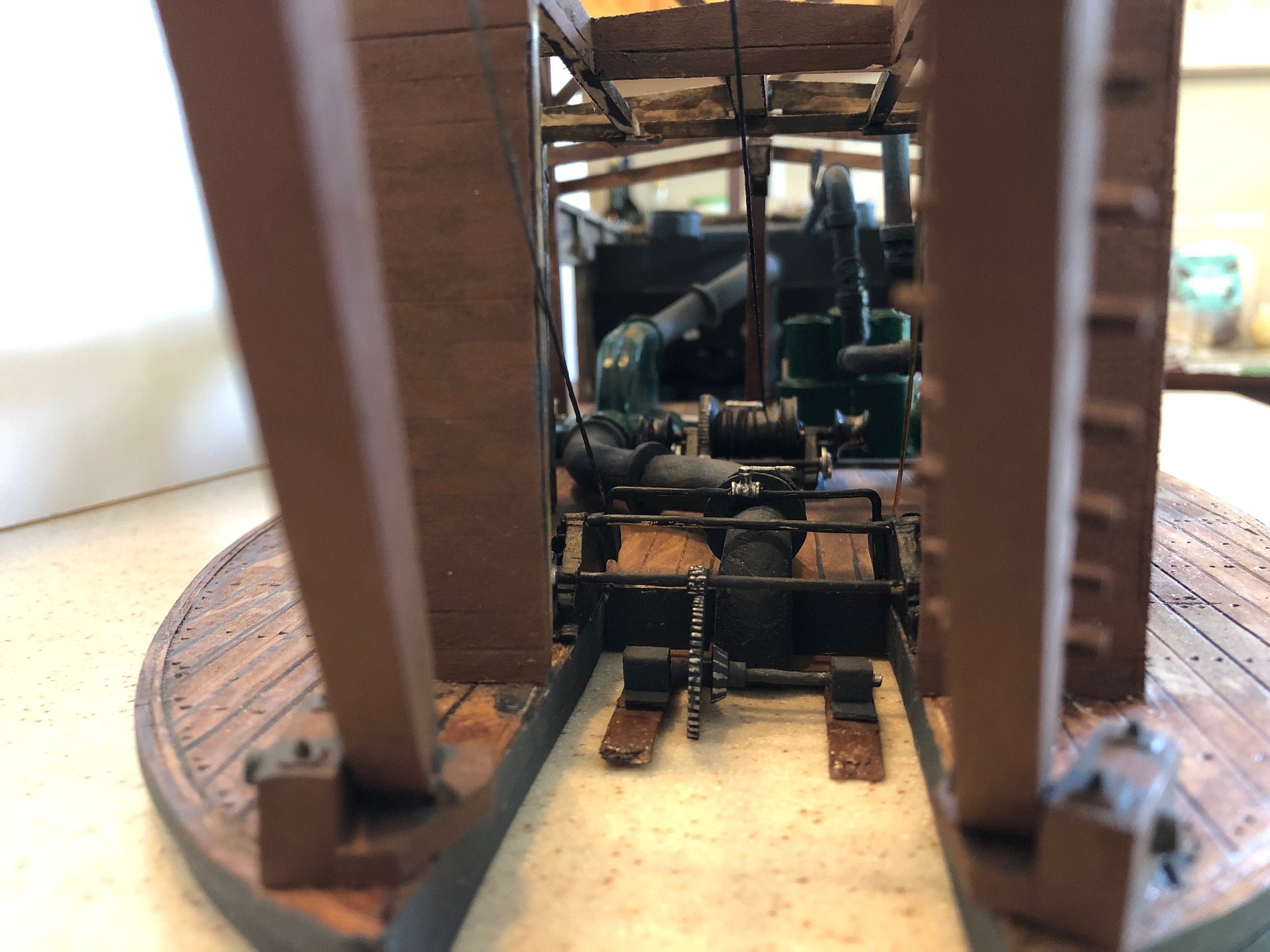
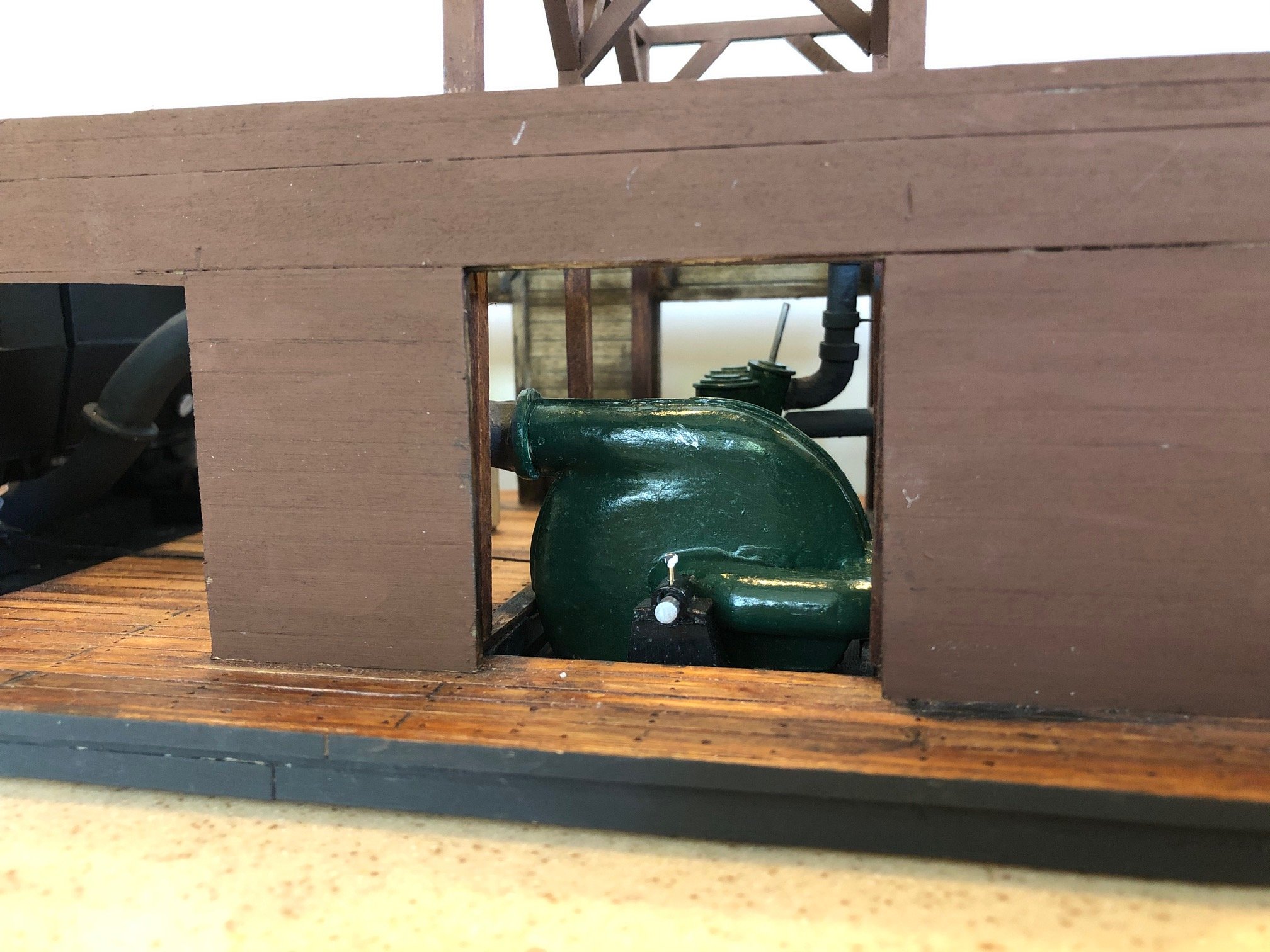
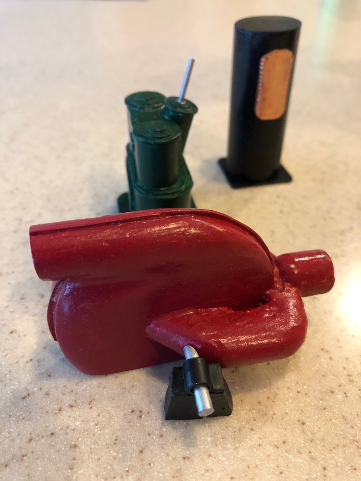
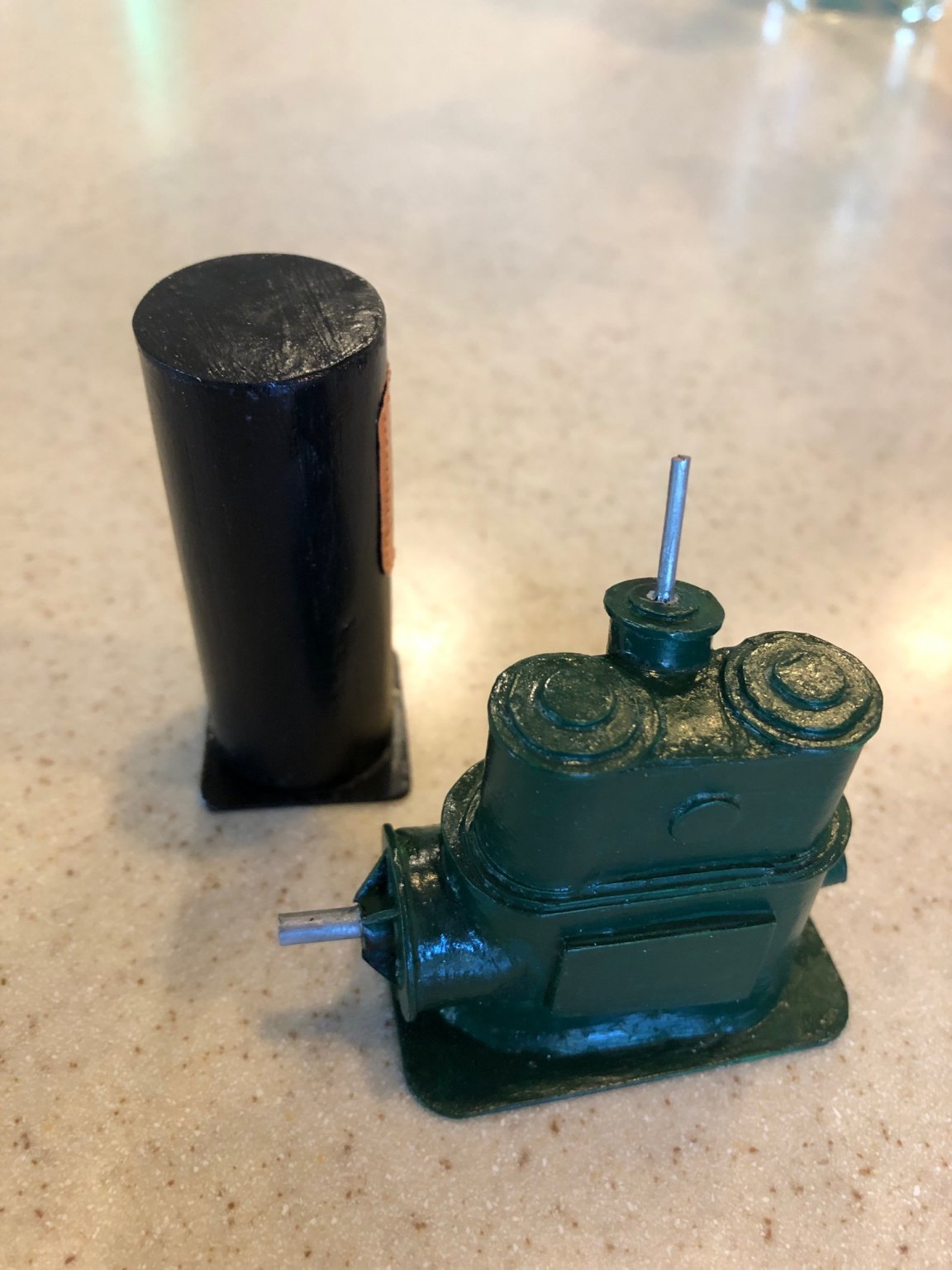
I have assembled and painted two steam winch kits from Bluewater. The winch raises and lowers the suction snout. I modified a second winch kit to represent the steam powered drive for the auger on the business end of the suction pipe. John, At your suggestion I painted the red centrifigul pump green to match the engine. It does look a lot better
-
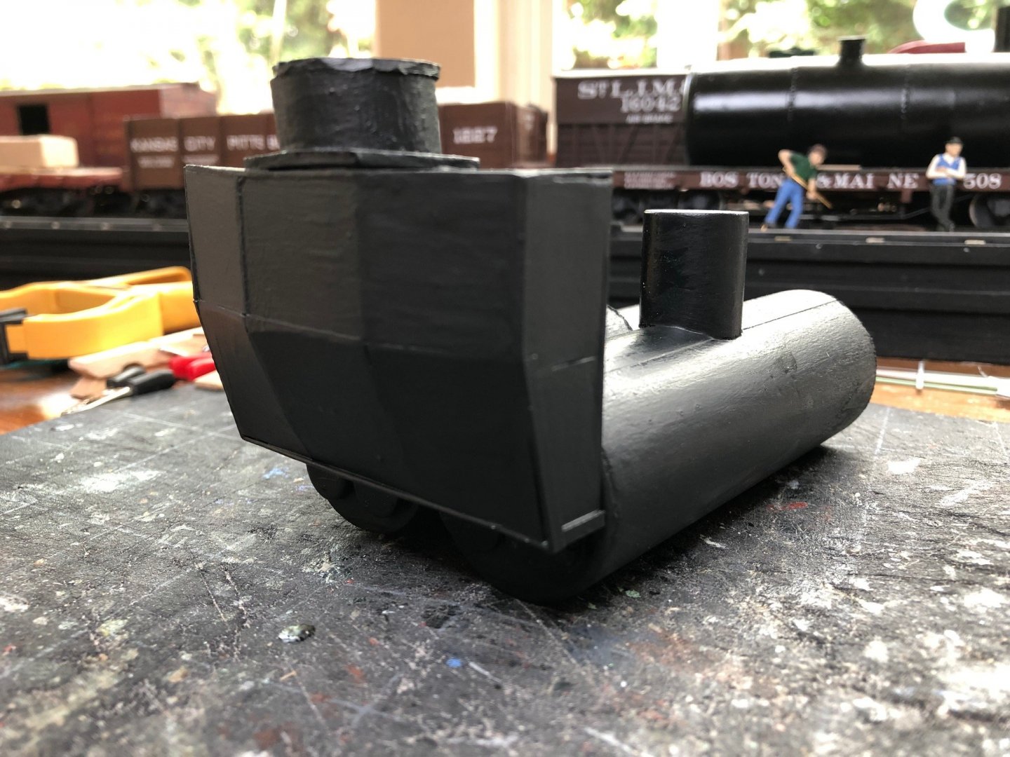
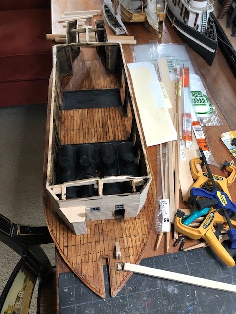
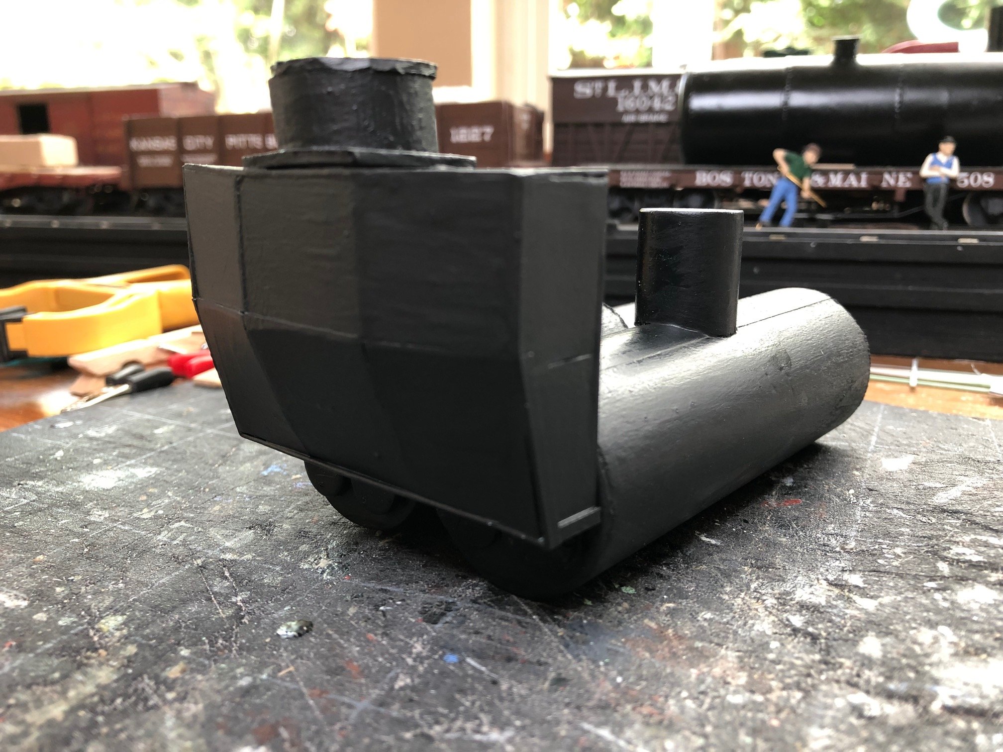
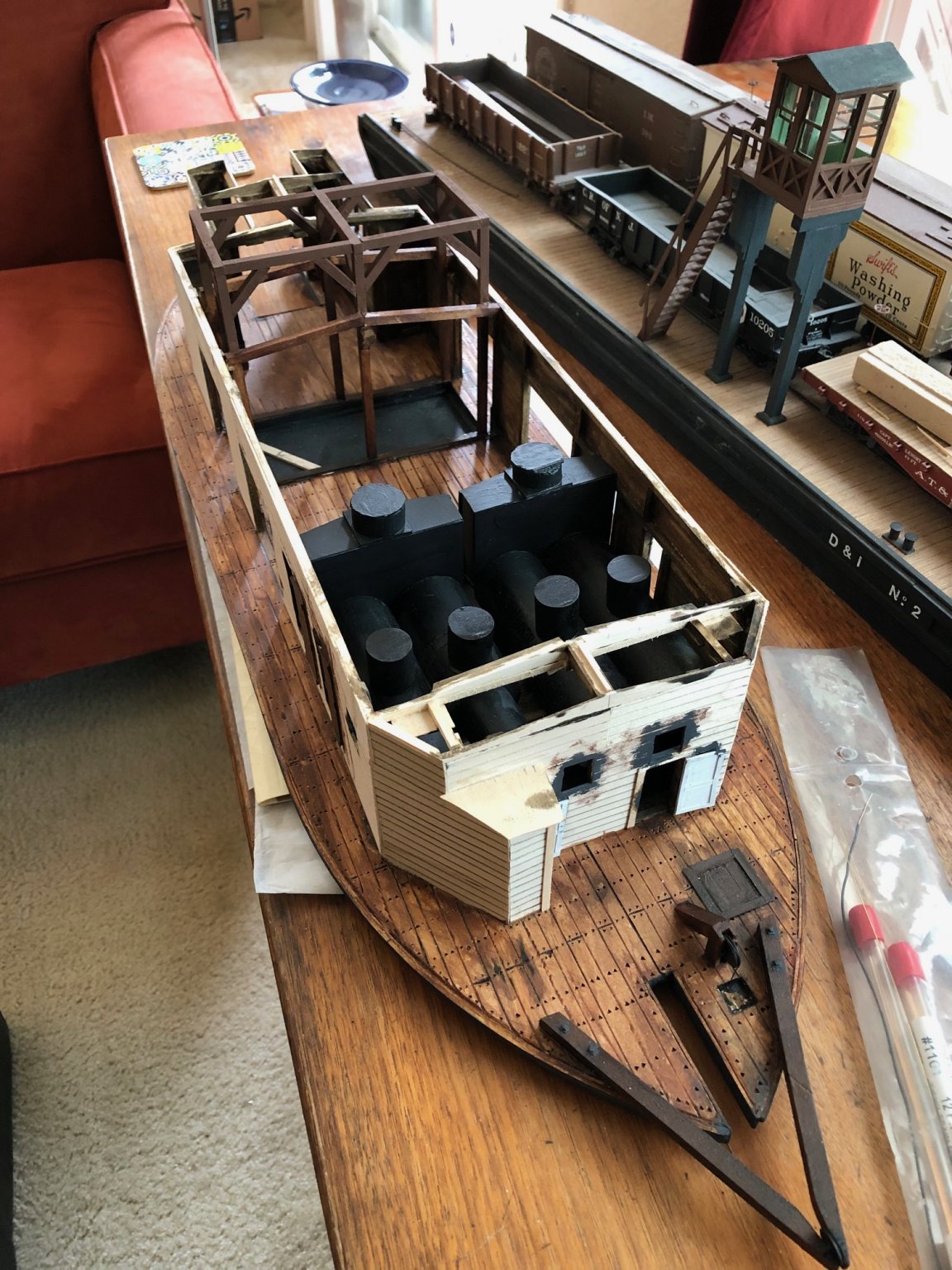
I have finished the smoke boxes. There are four Scotch boilers on the dredge. They must have needed a lot of steam. The boilers are paired and each pair shares a smoke box and stack. I have not made them very detailed as they will be in deep shadow but they follow the form and dimensions that I can see on the plan.

-
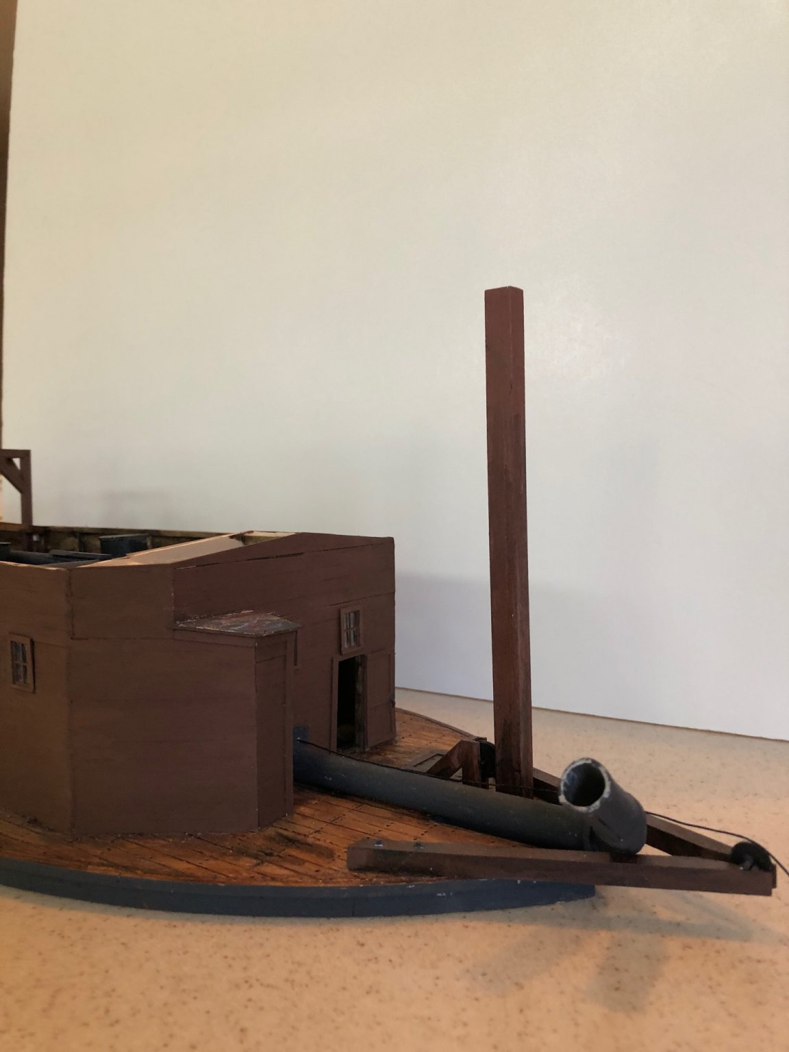
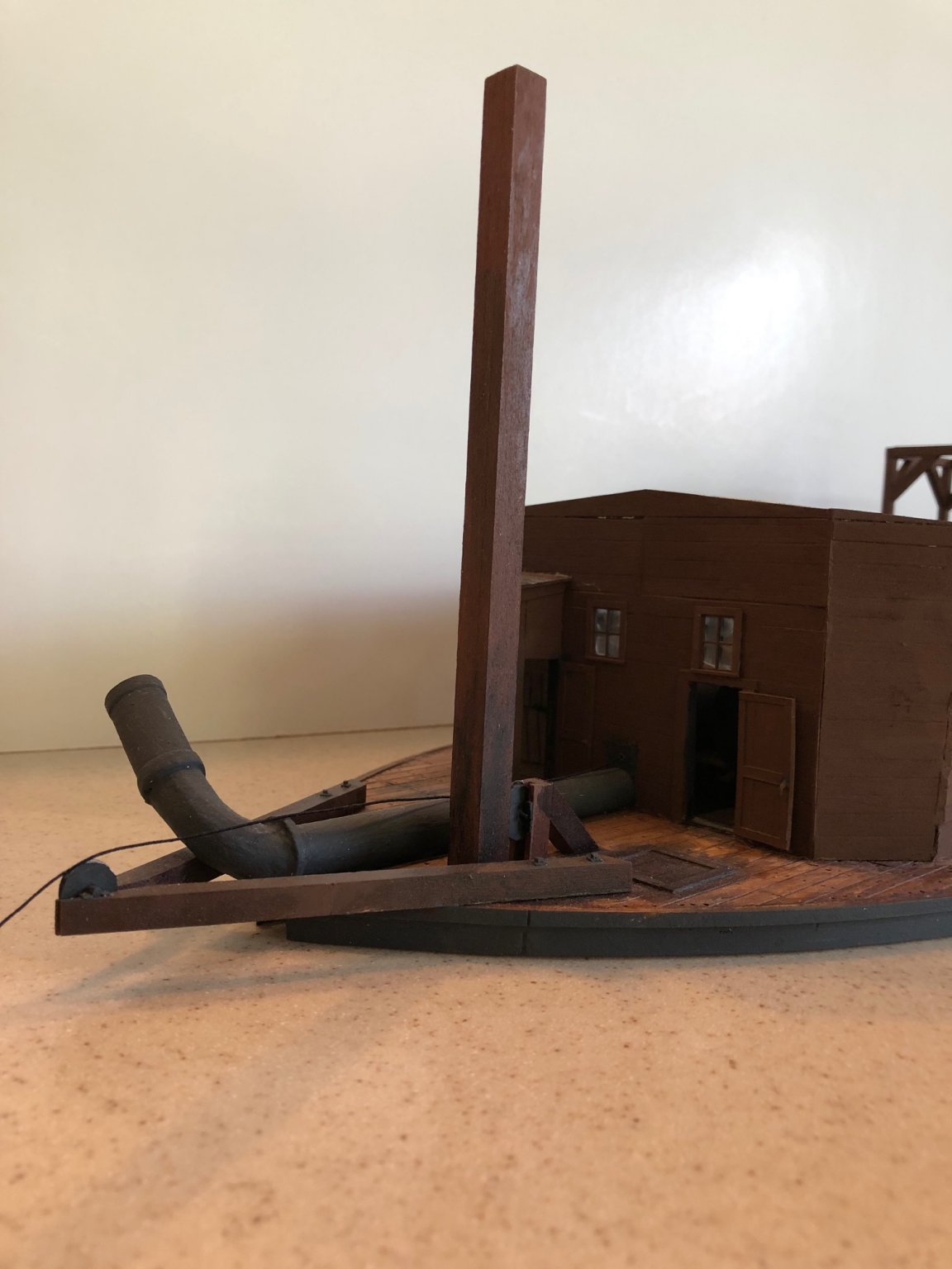
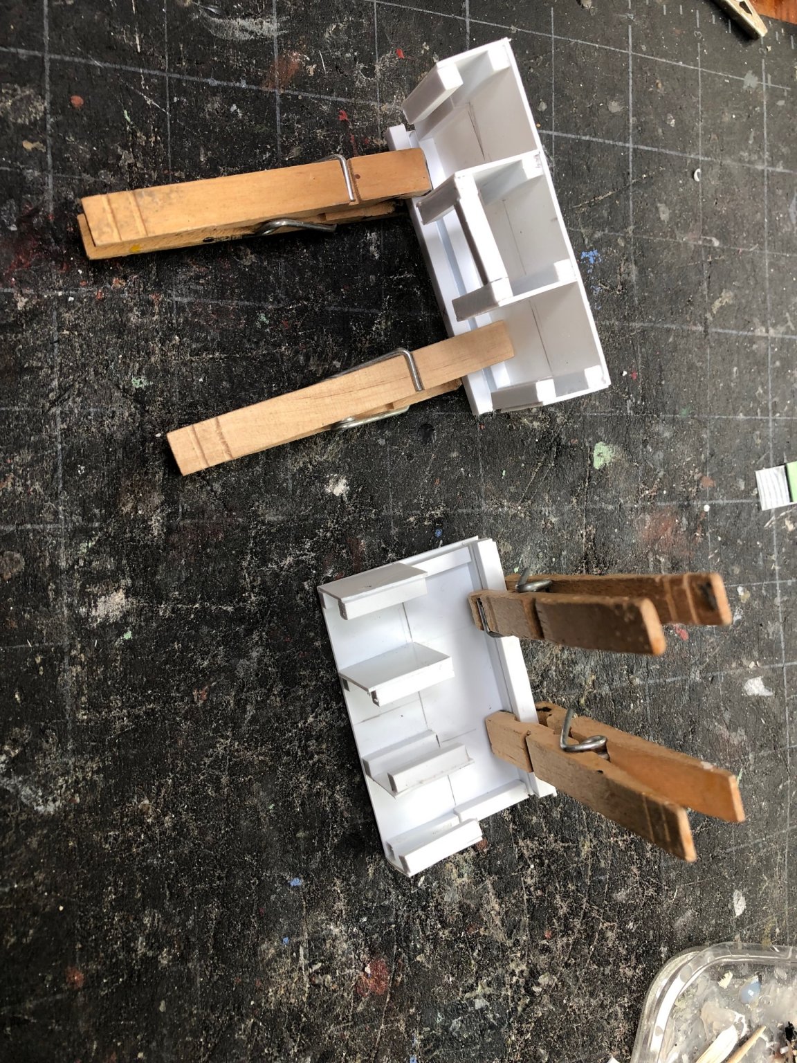
I have been working my way forward with the deck and deck house fittings. Here is the stern with the booms from which the pusher leg was suspended. I have added some scratch built doors to the rear of the deck house. The only thing I know for sure about the rear of the deck house is that there was a high window. I have also started to build the exhaust manifolds for the paired Scotch boilers. I am building them out of styrene plastic.


-
Here is the dredge machinery laid out for a test fitting: centrifigul pump, engine and condenser. Second image shows the Westinghouse high speed engine and the condenser. . These models are more representational than actual models. I tried out various machine colors on them. I don't have actual specifications for color. I still have to figure out how to represent the piping. Any advice would be appreciated.

-
I am having trouble sourcing or creating pipes and pipe fittings in 1:48 scale. The vessel I am modeling has 18 inch and 24 inch pipe for a dredge and steam plant. This includes some curved sections that curve in two different planes..
-
Ha Ha! Yes. It does now that I look at it. I should put some of those paper feet on it.
-
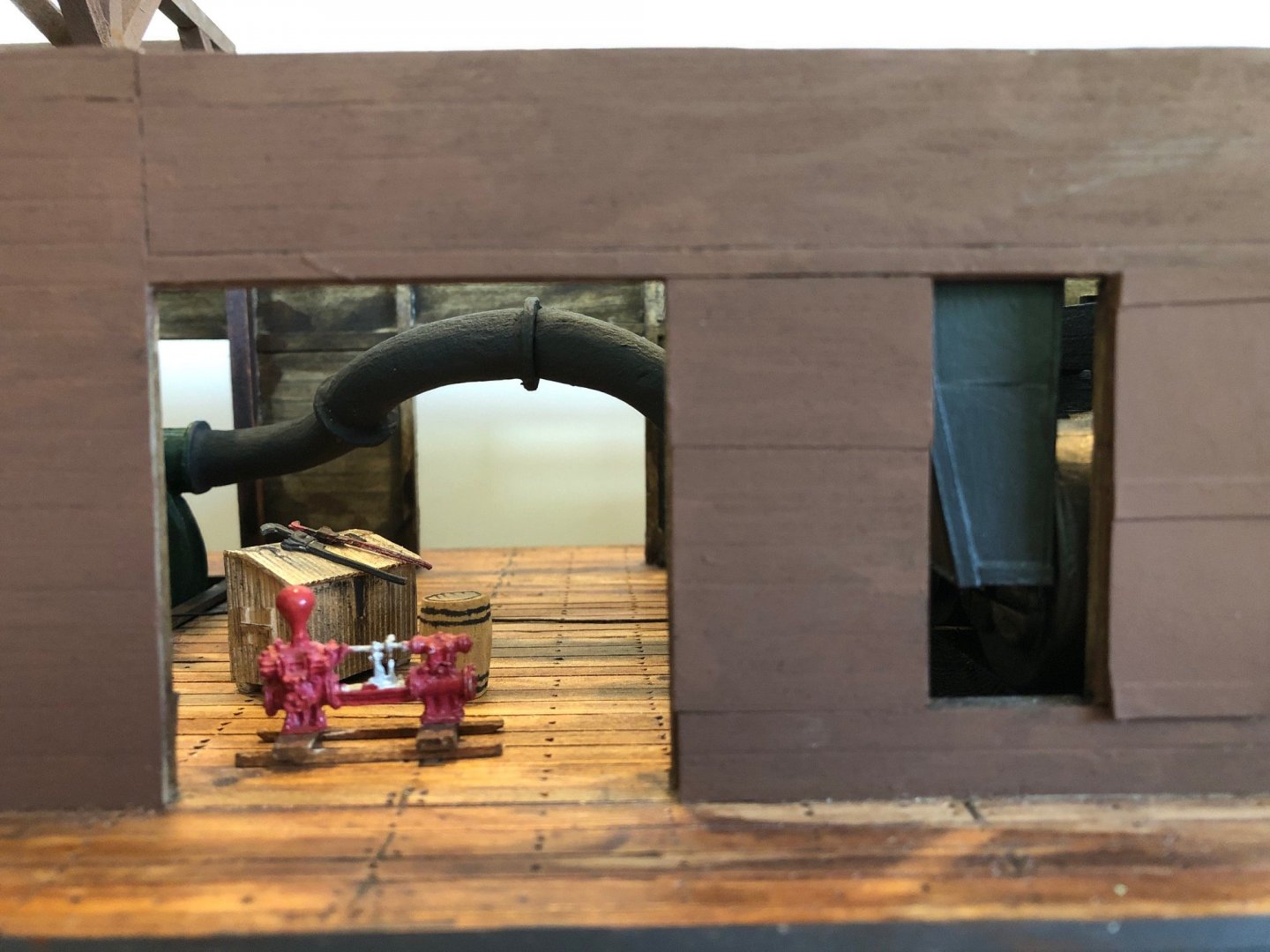
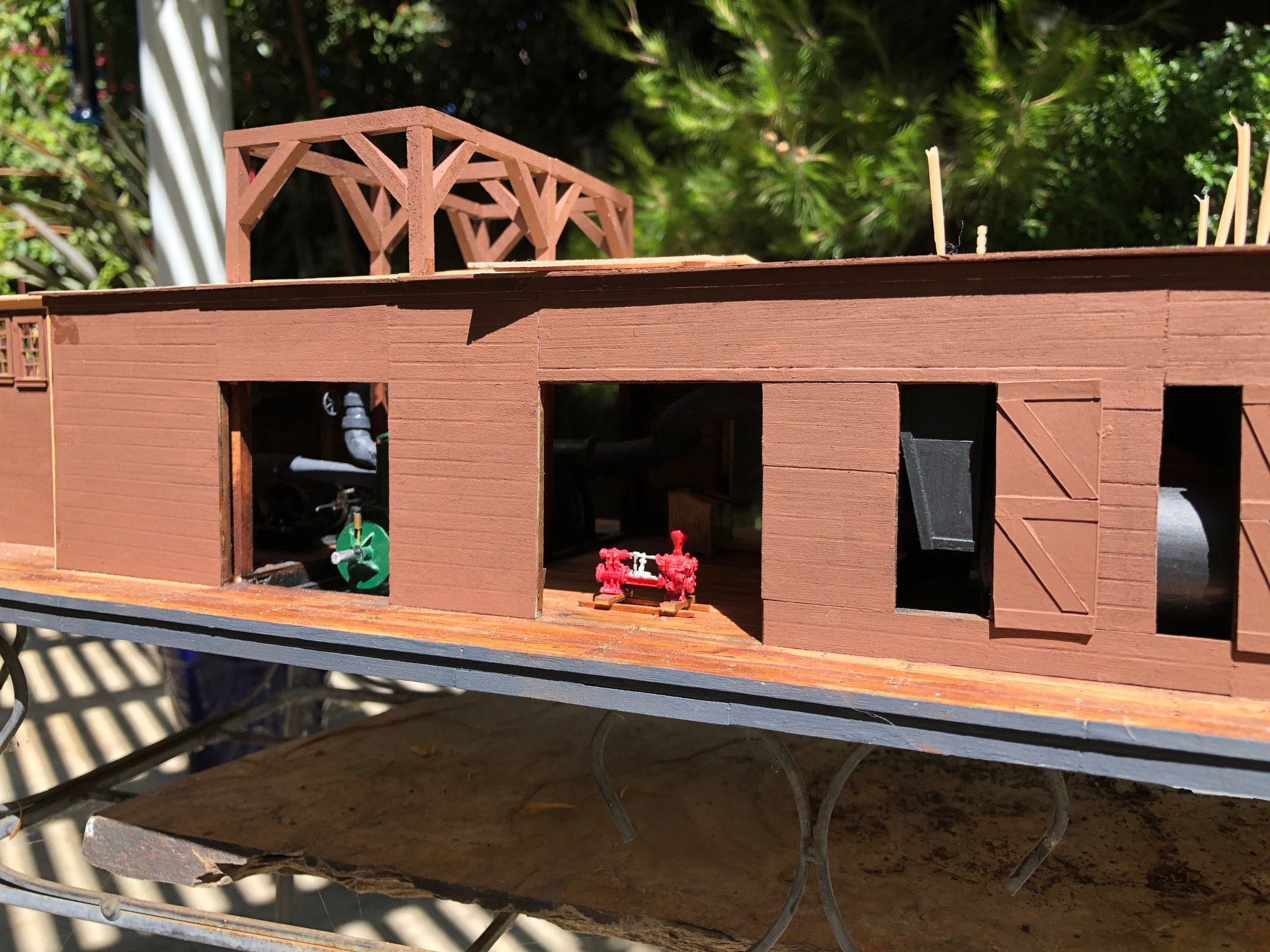
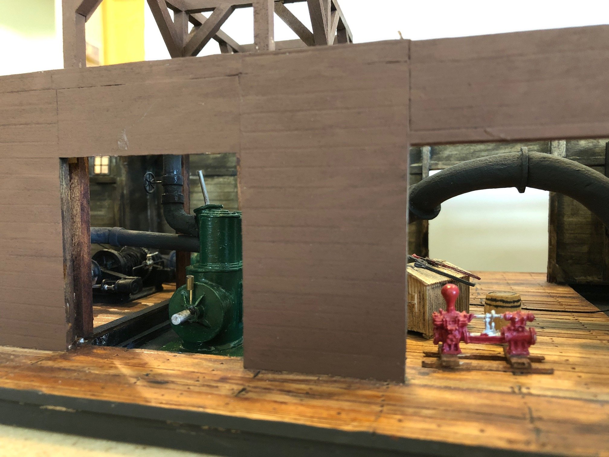
I have been working on the pumping machinery. Here is test fit of the centrifigul pump and behind it is the engine (supervised by the engineer leaning casually against the door frame). The dredge had a sort of heavy timber scaffold over the equipment bay. I have seen this feature on other dredges. It is connected to the derrick that the suction tube is suspended from. It might also be used to service the heavy equipment located in the bay below so I think I will make a roof hatch below it.
.thumb.jpg.84a29090e2d5897a3ec3c69d6cddf199.jpg)
-
I have begun to model the pumping machinery in the dredge. I discovered a set of drawings of the steam engine that I am sure was used to power the centrifigul pump. Westinghouse made high speed steam engines at the turn of the 19th century. They were mostly used to drive generators which is probably why Westinghouse got into the steam engine business. The engine is a two cylinder engine with an enclosed crankcase. The cylinders were simple. Located between the cylinders is a valve cylinder that is canted off at an angle from the vertical steam cylinders. This shows clearly on the plan of the dredge. The pump is very big -- around 9 feet in diameter.
-
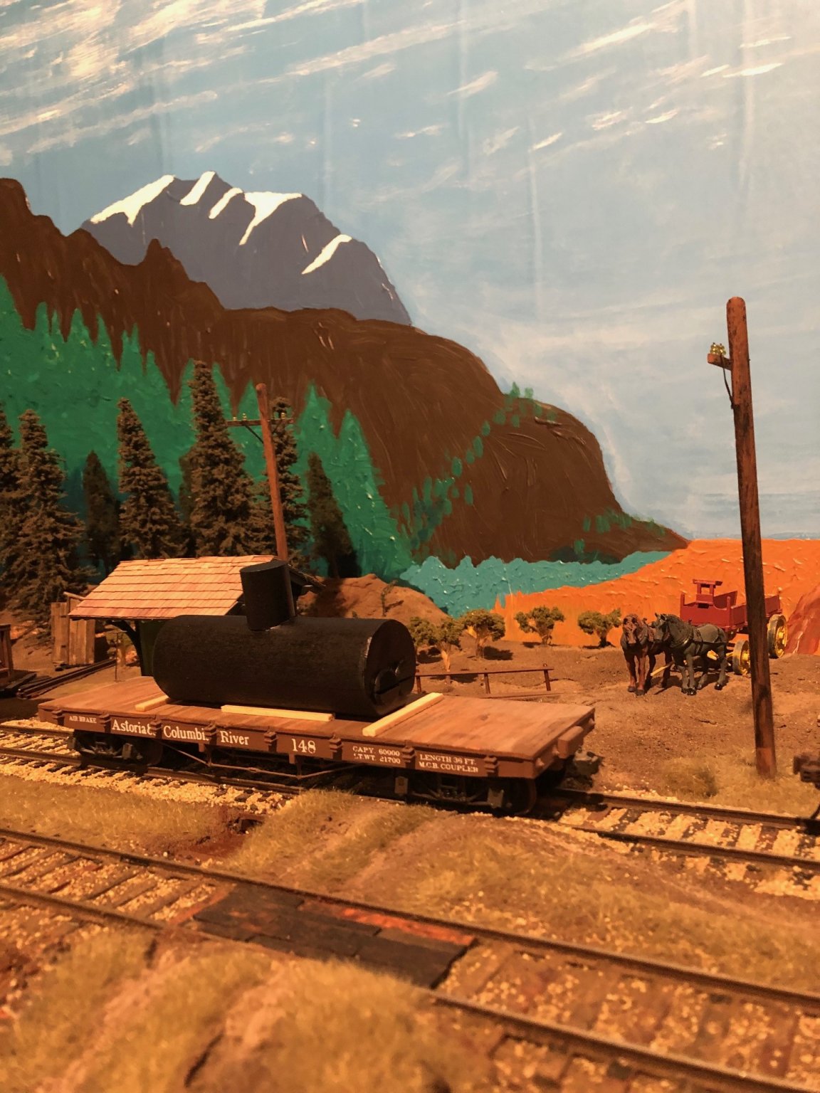
Yes. I am building modules in 1:48 scale. This will be a part of a harbor scene where I can highlight nautical models as well as maritime railroad operations.
-
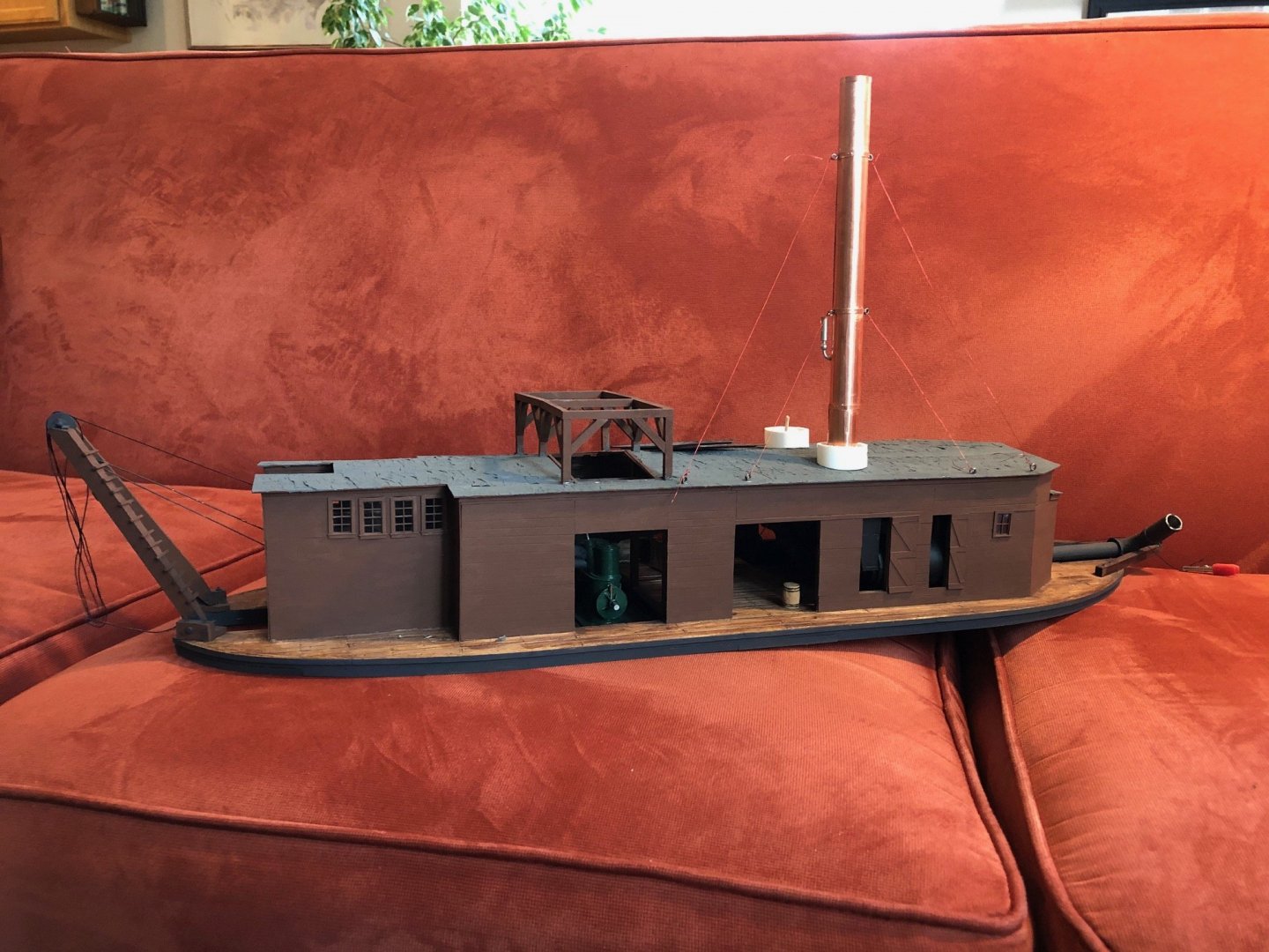
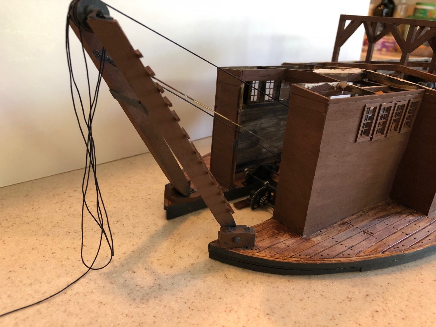
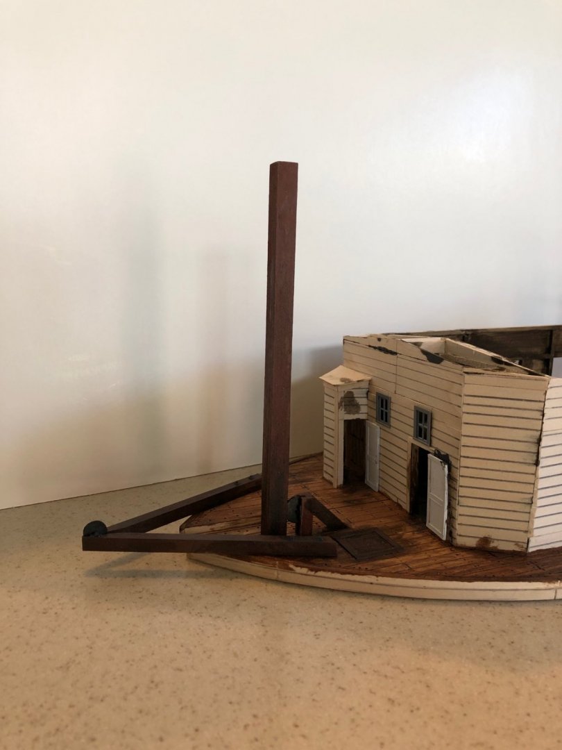
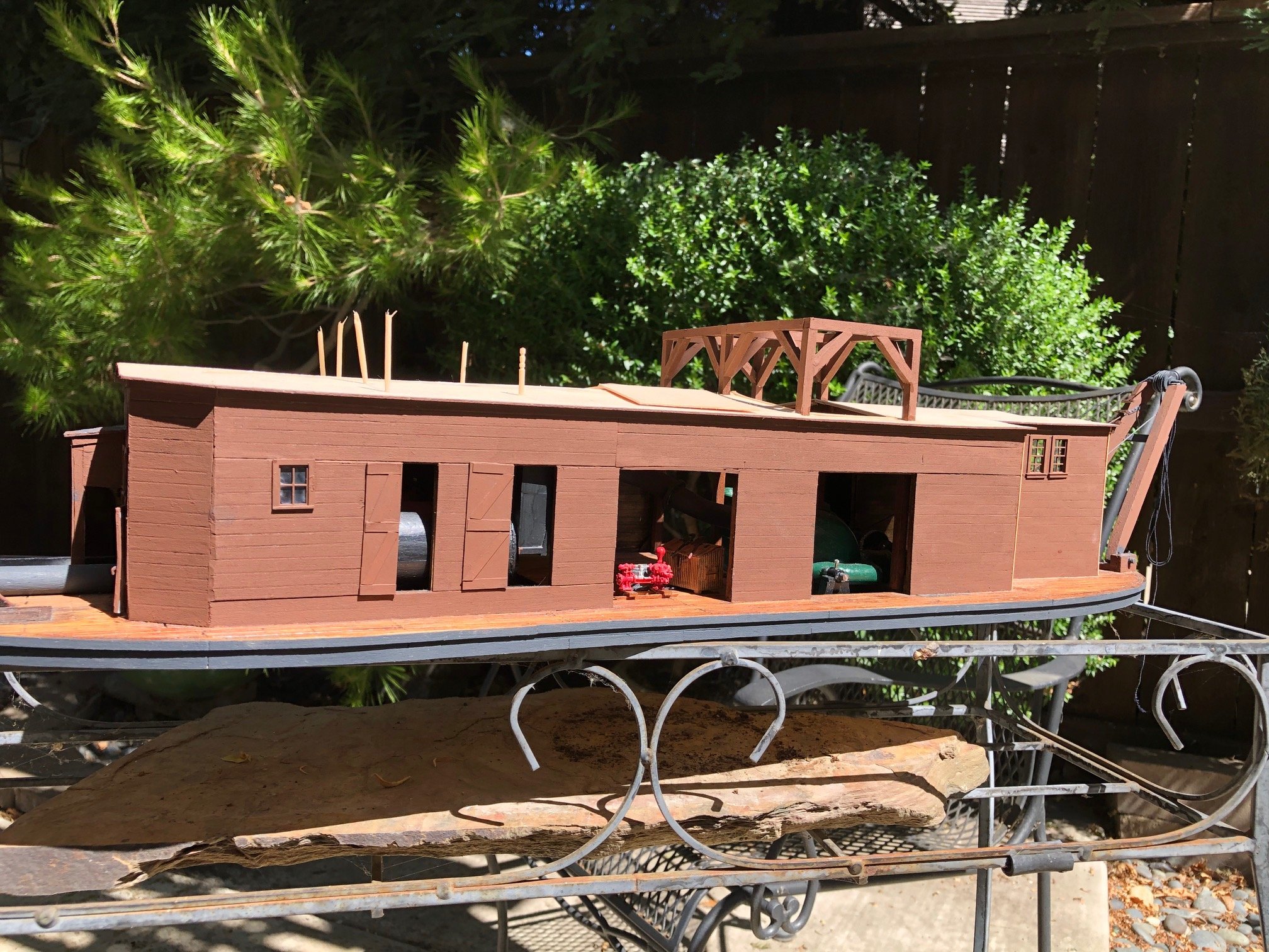
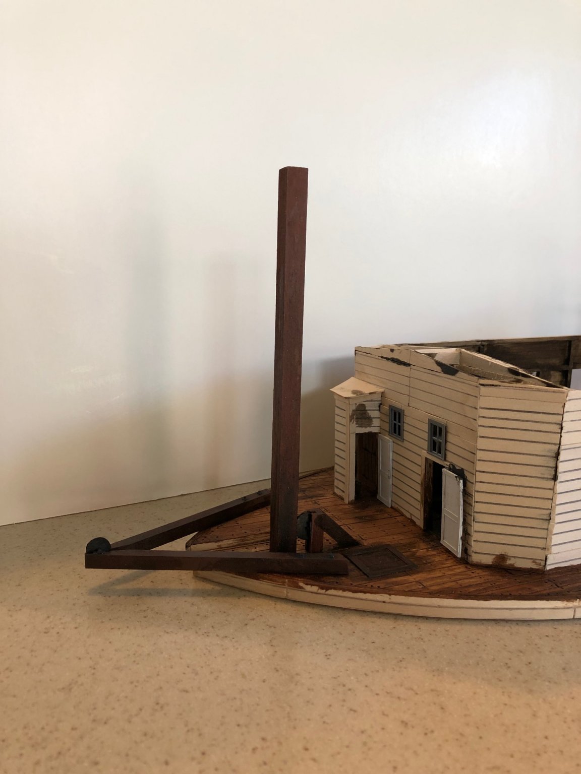
Here is the spud lift mechanism and the spud painted and in place. The spud was lifted by what I assume was a wire rope over the large diameter pulley. There was a steam powered winch under the deck. I plan on painting the hull black and the deck house a mineral red. The harbor is getting pretty crowded.

-
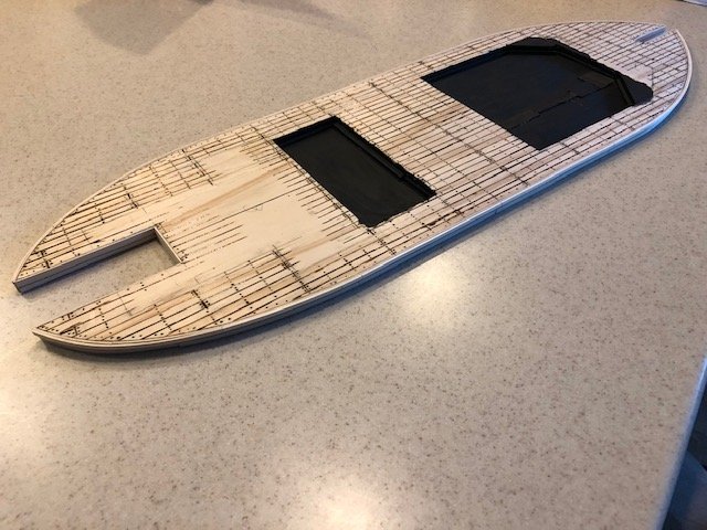
I have stained the deck and interior of the deck house. This is so I can start to install the machinery and other details. I stained the deck with a brown shoe polish and alcohol stain and the interior of the deck house walls with a black shoe polish and alcohol stain. I think they would not have bothered to paint the interior walls so they just got smoky and had dirt and machine oil thrown on them. I have test fitted the paired boilers in the deck house and the window frames. I have made the spud which is a huge 17 inch by 17 inch timber that will extend 27 feet above the deck. I am building the framework for the mechanism that lifted the spud.
-
I have finished putting the siding on the deck house and have started to develop the roof line of the deckhouse. I don't have a cross section to work from. I wanted it to appear that it could shed rain. So I decided to give the roof a low slope -- something like 1:12 -- from a longitudinal ridge line. There is a curious little framed outline at the stern. I don't know what it was. Maybe it was a head or outhouse. A enterprising photographer caught one of the four boilers in transit to the shipyard. The boilers are more representational than detailed models. They are going to be mostly hidden in the smoky, steamy boiler room.


-
I have framed the sides of the deck house. I have been looking on the internet for images of the steam engine and pump. I found one image of a smaller set up. It looks like this kind of direct connected arrangement was most commonly used to power electrical generators. The drawing of the dredge seems to show a two cylinder, simple, high speed steam engine. The crank shaft of this engine is directly connected to the pump.
- 69 replies
-
- 11
-
-
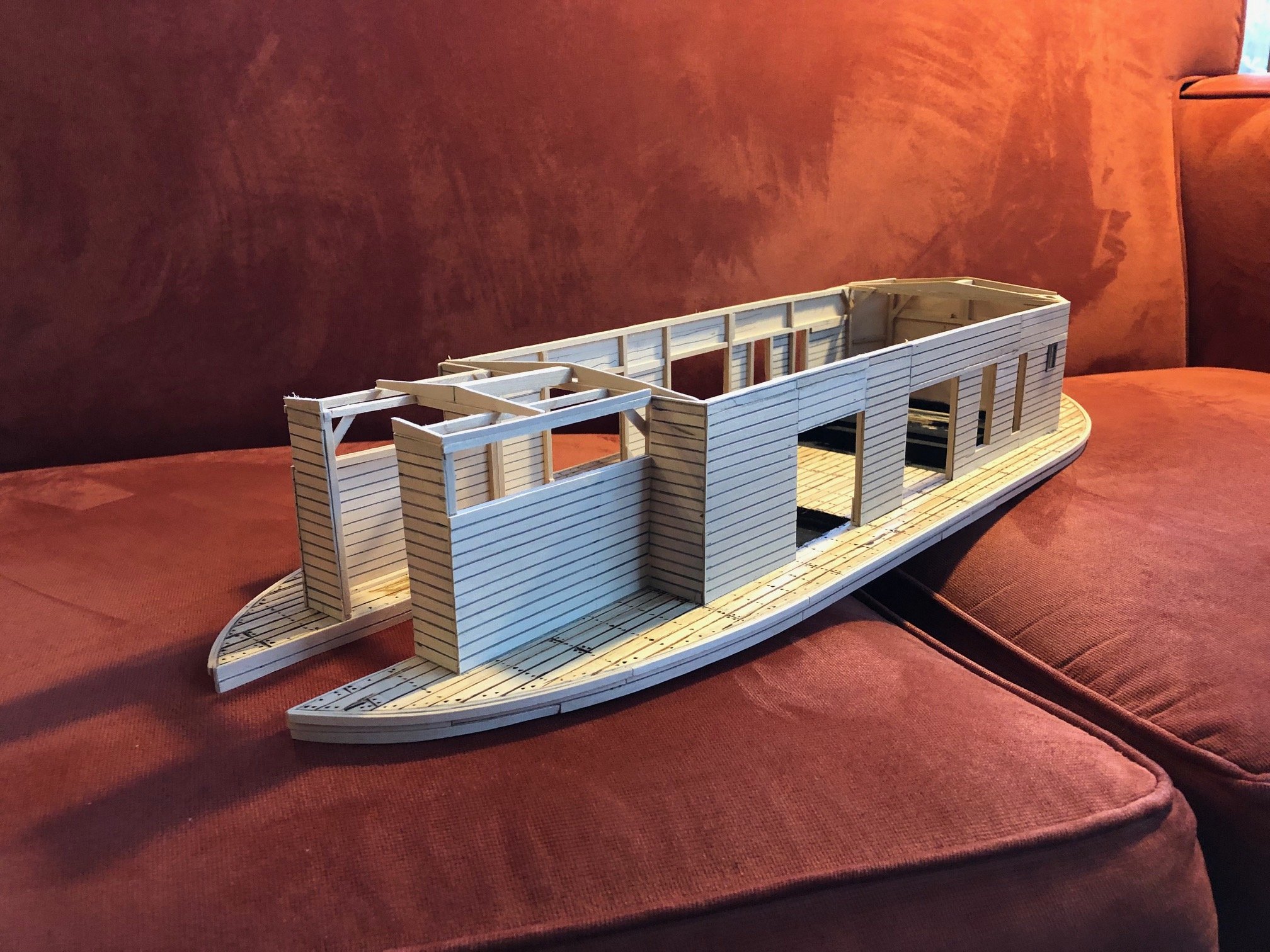
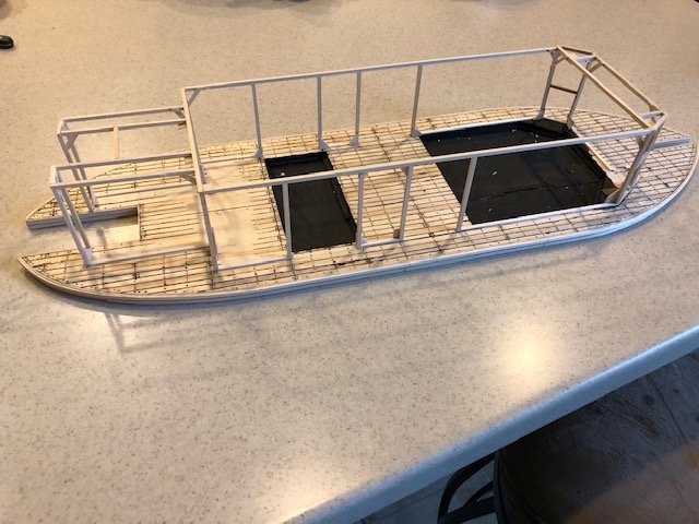
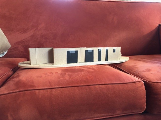
I have installed false bottoms in the holds where the boilers and the pump will be placed. I painted them flat black to improve the illusion that they are at full depth. I made a mock-up of the deck house to see where the openings fit. The plans do not show the doors or windows other than the windows at the bow. There is one image of the dredge as-built that shows big openings in to the location of the pump and into the bay in front of the boilers, two tall narrow openings or maybe vents at the side of the boilers and a small window toward the stern.
-
Brian, Great model. Thanks for sharing your experience. Maybe somebody already mentioned this but there is 1:1 MSO under preservation and restoration in Stockton CA, USA. It is the Lucid.


.jpg.d16709cd71cefbeebe56581107dacda6.jpg)


.jpg.a0d73d5ff18c857c488a9268f4f4fa9d.jpg)


.jpg.6f1d899c7916c48b5d4878415ca10068.jpg)
.jpg.63779a32cdcdfe5d16934335eb464e48.jpg)


.jpg.1960622cc296a9806f22b9dcda51610d.jpg)