MORE HANDBOOKS ARE ON THEIR WAY! We will let you know when they get here.
×


The Bitter End
-
Posts
257 -
Joined
-
Last visited
Content Type
Profiles
Forums
Gallery
Events
Everything posted by The Bitter End
-
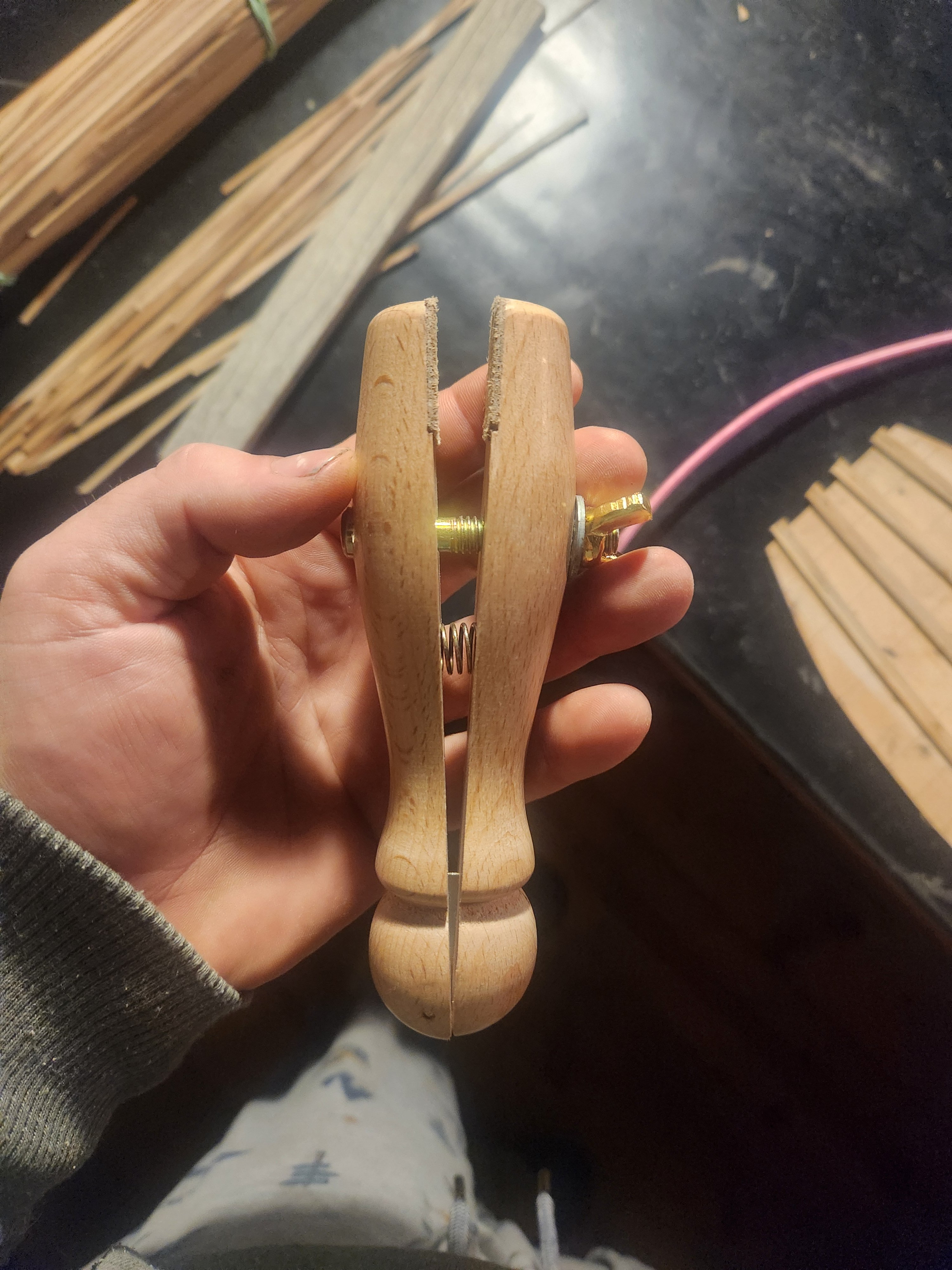
 It might be worth buying( or making) a jewelers clamp. It's essentially a cylinder of wood which has bee split down the middle with a wing nut through it and leather gripping faces. It may help. Beautiful work so far by the way. Haiko
-
Thank you good sir! I am leaning in a similar direction now that I have cleaned the planking a little more. I will post the completed deck before I make a final decision. Cheers Haiko
- 193 replies
-
- 4
-

-
- Model Shipways
- constitution
- (and 5 more)
-
Hi Jon This very thought is occupying a vast amount of mental real estate for me, and you are totally right!(It's basically an act of madness). I am torn between the balance between accuracy and effort. I am coming to accept that I will certainly have to put a lot of the deck furniture in for this gun deck, a lot of which will also never really be seen. I can't really argue with you as you make a very good point but I sort of justify it in the following ways. 1. Firstly (and most importantly) I am really enjoying the process of historical research to get an accurate idea of what she really looked like. In a small way the process of actually building these features has lessons about construction woven into it. I am not sure how far I would go with this but for now I'm quite liking aiming for as close to perfection as I can manage. 2. This deck has been a learning curve for me. this is only my second build and my last deck is but a distant memory. It has been a good opportunity to figure out what works and what doesn't without anyone actually seeing the results too plainly (the stained glue for example was an experiment which needed testing). It has also provided some much-needed practice in planking. 3. I try to view each step in the model as something worth doing in and of itself. I am not in a rush to build this model and when it's done I will just build another. A big part of this hobby is an opportunity to do things simply for the joy of it and not for the result. I have a job which is very much goal driven and this is a form of meditation. there is something about making a great effort for something which will never be seen which adds to this. 4. I do intend to leave at least some of the hatches open (possibly like the Antczak model) this means that the most curious of observers MIGHT notice the ludicrous decisions I made on the deck below. 5. I think it might provide a bit of information or help for someone who is building a more open decked model, and it is nice to share this process with the good people of this forum. Even your question has made me think a little more about why I am doing this, and it has added something of value. I can't guarantee I will be able to continue this way, but I hope that I can. Please keep the comments coming. They are always welcome Cheers Haiko
- 193 replies
-
- 6
-
-

-
- Model Shipways
- constitution
- (and 5 more)
-
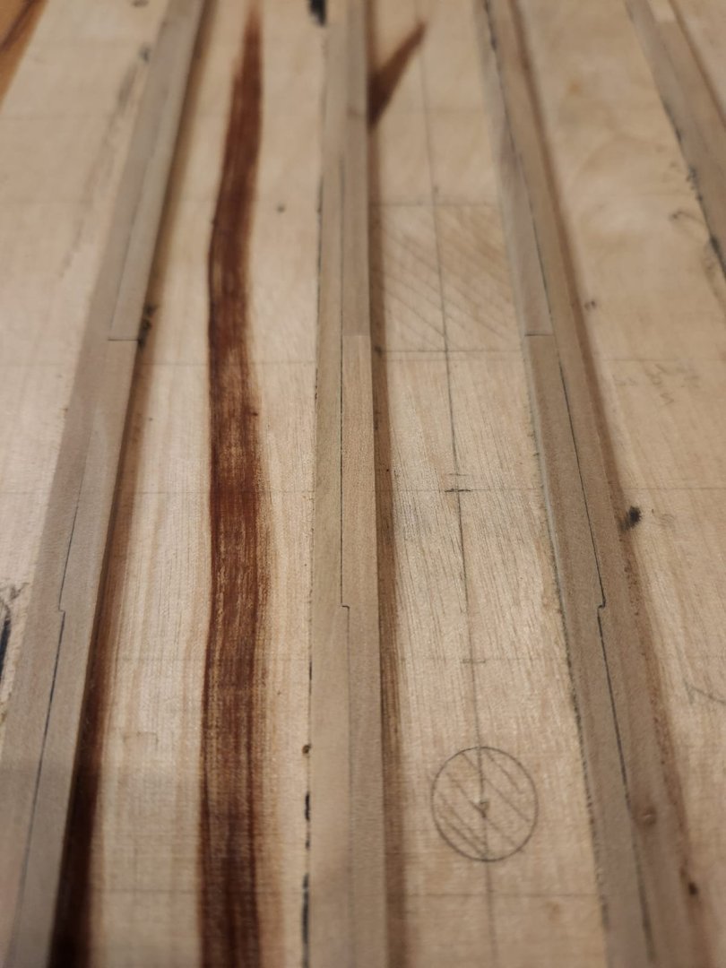
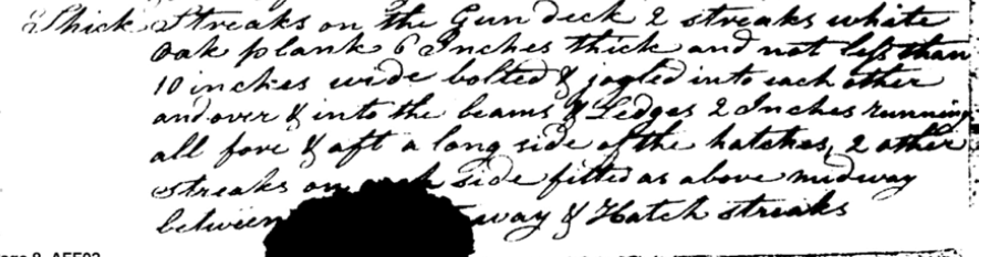
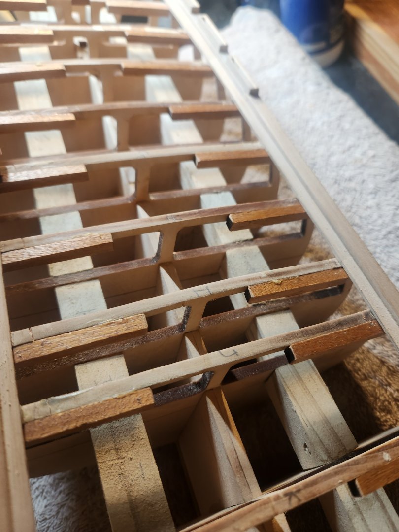
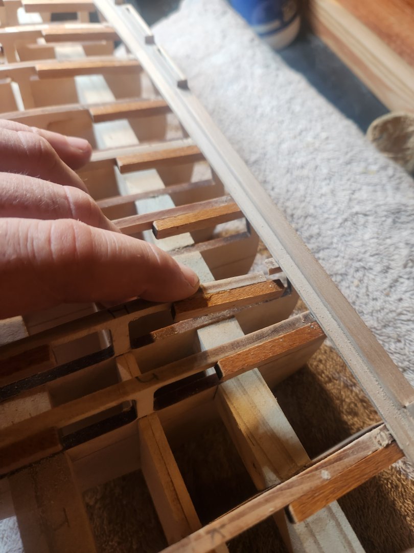
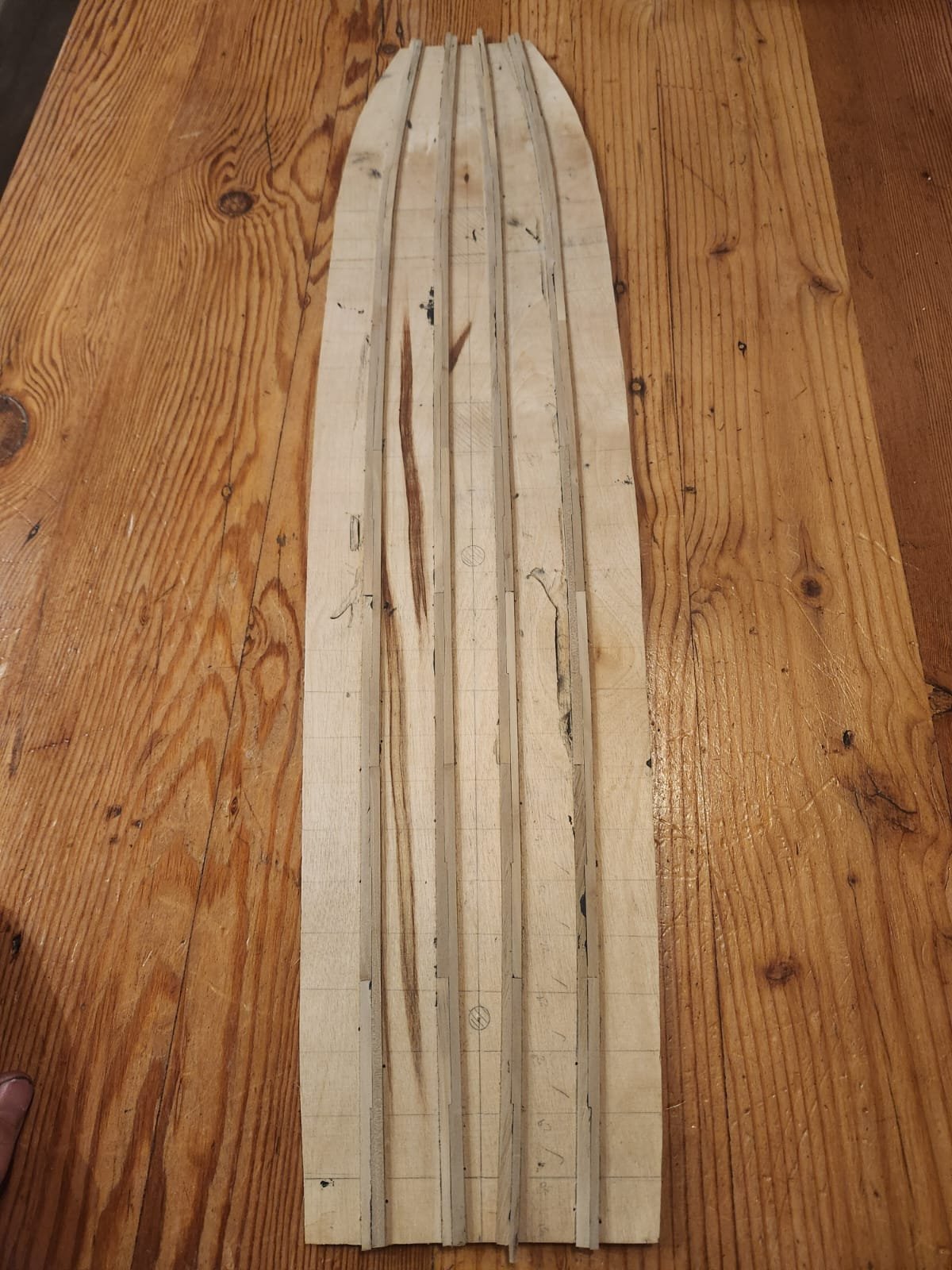
Hi Everyone This post comes with a disclaimer....please don't judge too hard. What you are seeing is very much a work in progress. These thicker strakes still need to be sanded back to show only a nice neat caulking line and no saw marks as well as some shaping on the sides of the curve to correct the end and get everything to fit well. this will be done just before and after the remainder of the planking goes in. This should produce a perfectly flat deck with neat even caulking. I have also noticed a lot of colour variation because of the trees I am using for planks, so I am open to suggestions on a staining method which will make a nice even deck without hiding the wood. A final point is that these thicker 2 plank strakes do look very wide. They are however exactly to the original spec mentioned. with a minimum width of 10 inches at full size. I began by cutting a suitable sized board of chipboard counter top from an old project which would produce a flat and sturdy surface to pin the carrier deck and guide pins to without damaging my desk. I then placed and tacked the "inboard" thick stake to the carrier deck while making sure it followed the curve of the line previously marked. This initial plank was secured using normal elmers tite bond original. wherever 2 planks would meet at the edge or ends I would use the same glue but mixed with an ebony wood stain. this produced a thick black paste which offers a pretty nice scale caulking line that is quite subtle. I did this until all the inboard planks were run down the length of the deck with a subtle curve. The next step was to interlock the next set of planks with the first. I achieved this by marking the center of each of the first planks so that the butt joint of the interlocking plank would land in the middle of the plank it locks with. I then just transferred the location of the joggling points and cut to size with a ruler and scalpel. I did make an attempt to soften the wood with surgical spirits but this definitely made things worse. this resulted in planks which were set out in this configuration(a big thank you to @Marcus.K. for the drawing below) This would make for a strong structure that offered support in both compression and tension. Once this had been done I measured halfway between the outside of the first strake of thick planks and the edge of the deck and marked a line at this point as per the Humphrey's instructions. Initially I Used this method to mark the line right up to the very forward edge of the carrier deck, but this produced an unreasonably sharp curve so I ended up making a more gradual curve from the 4th deck beam onward. Below is the rough planking result. Next up will be the remainder of the deck planks. Cheers TBE
.jpeg.3cd24d503a4309ae92d4247ddc41e9e2.jpeg)

- 193 replies
-
- 7
-
-
- Model Shipways
- constitution
- (and 5 more)
-
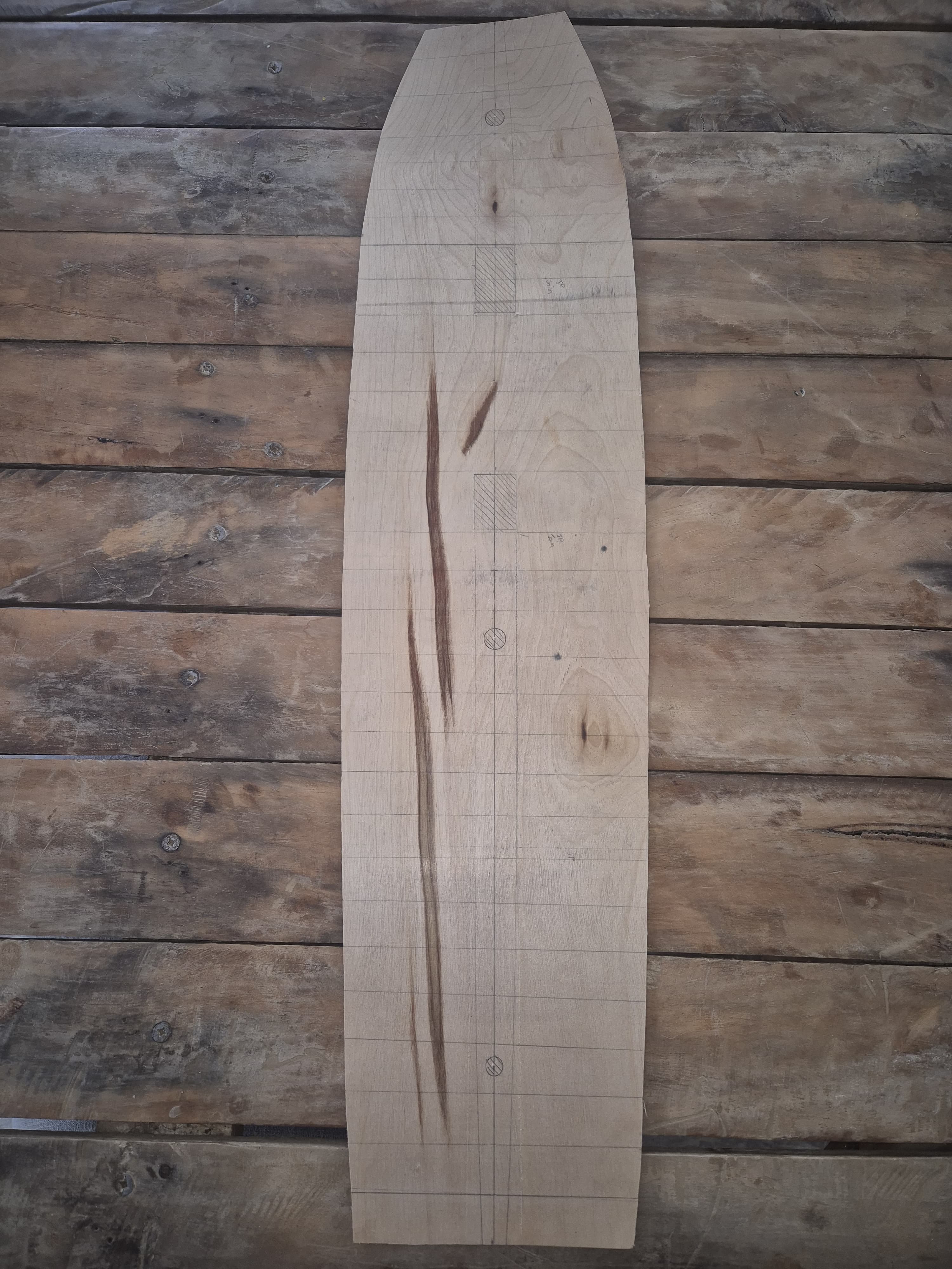
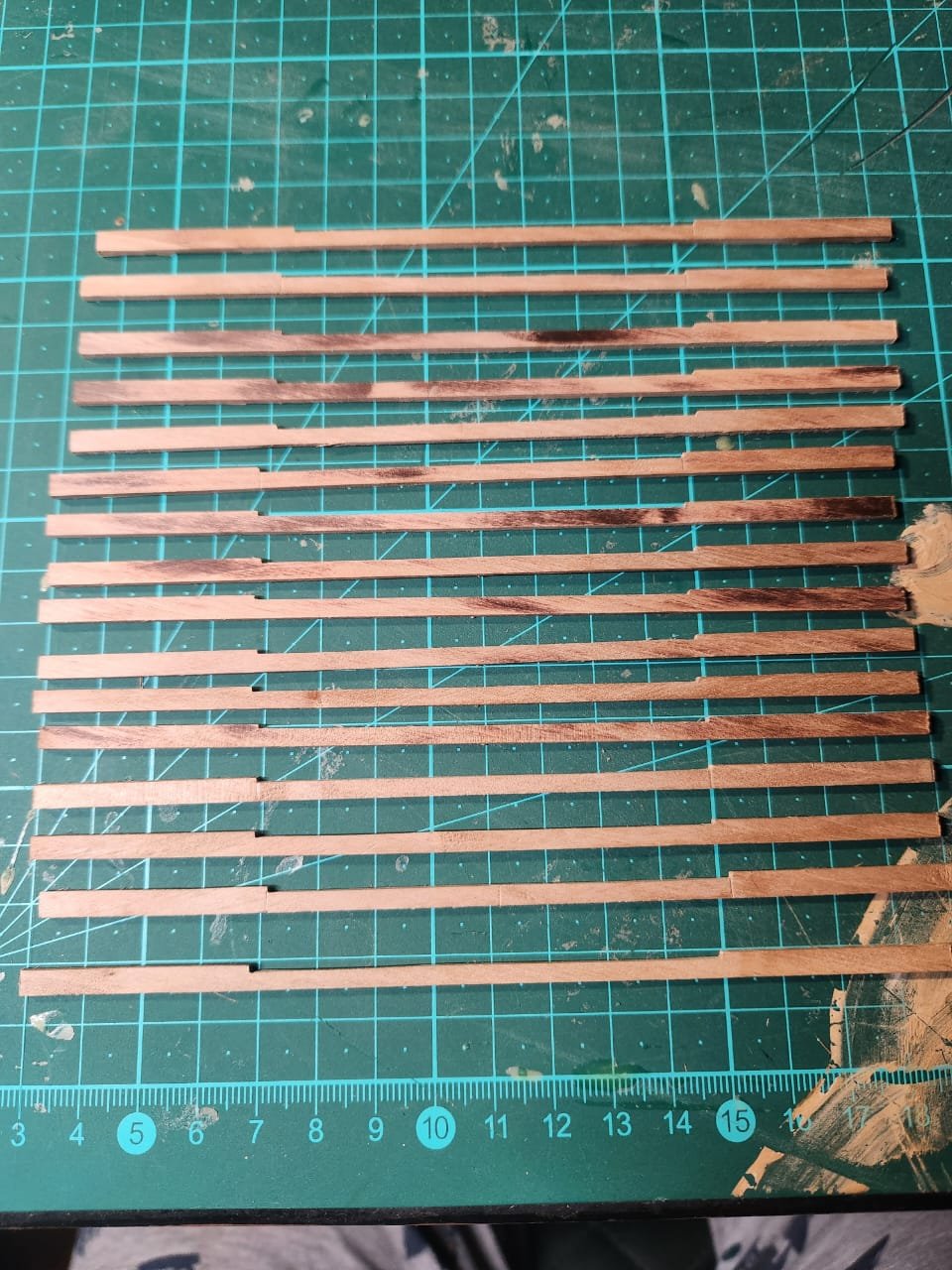
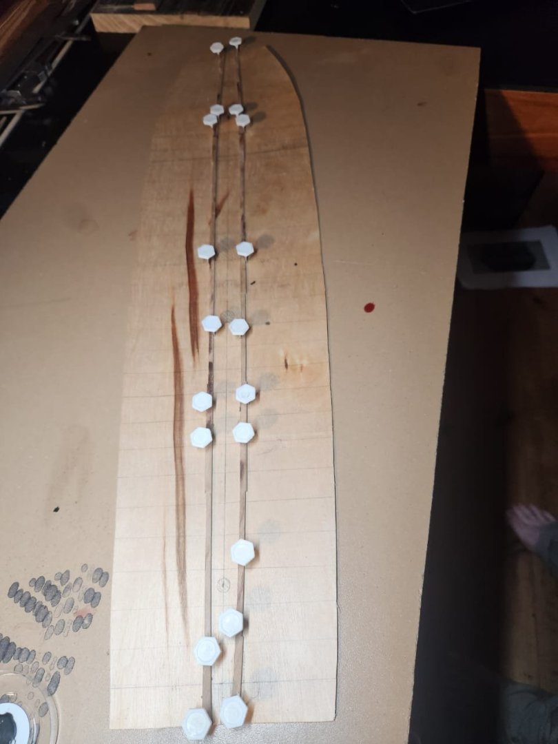
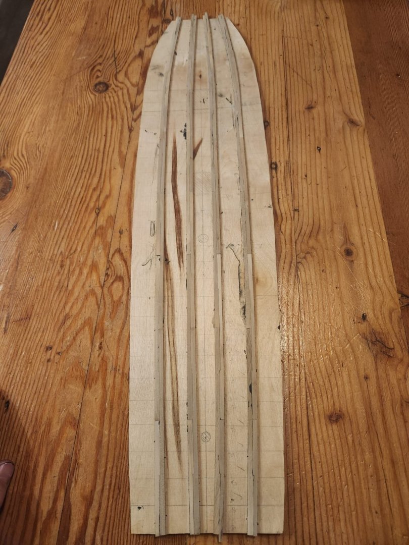
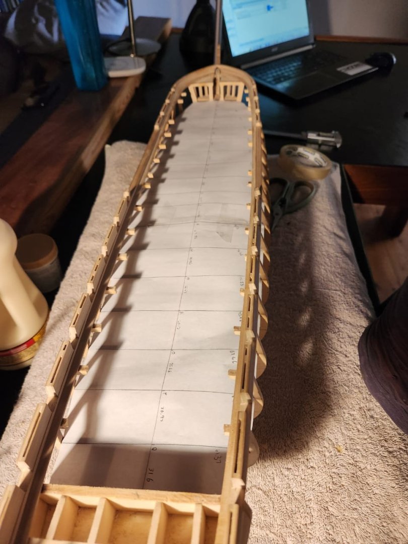
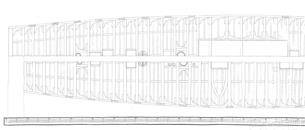
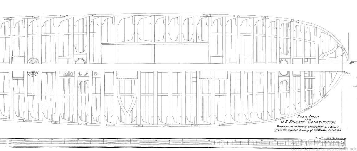
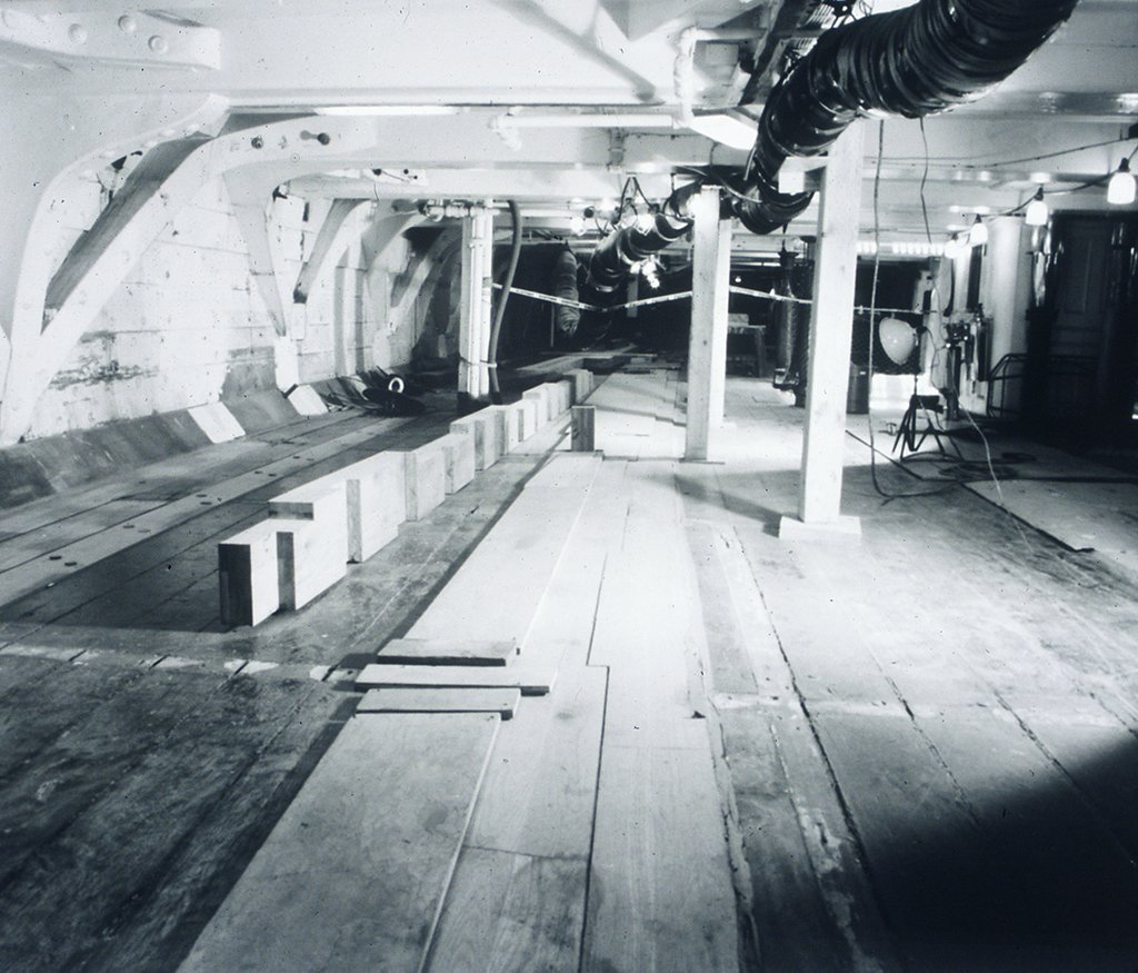
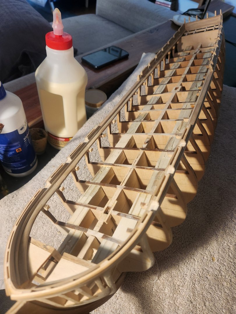
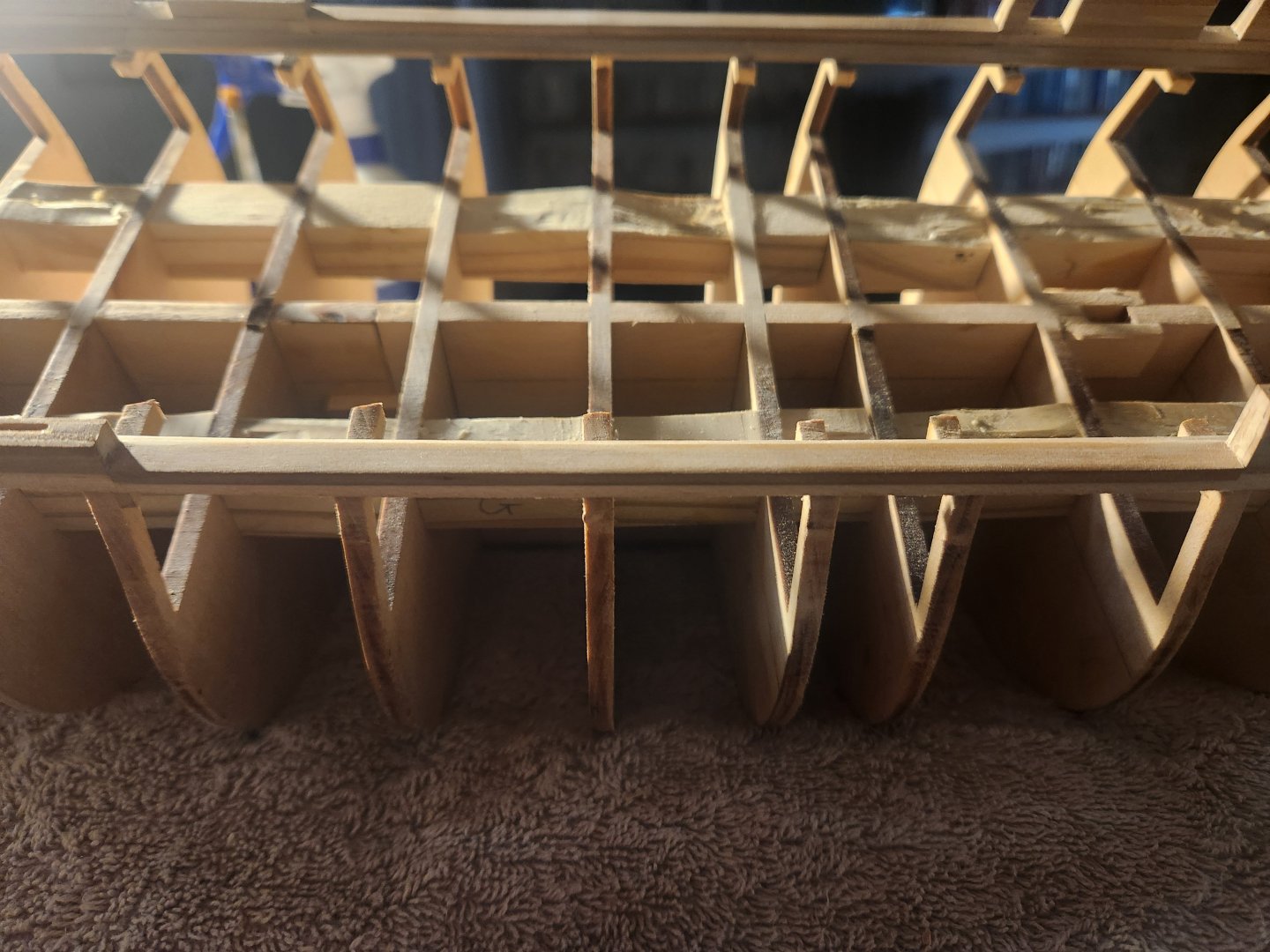
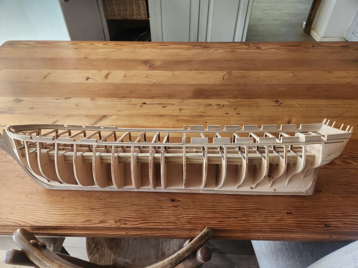
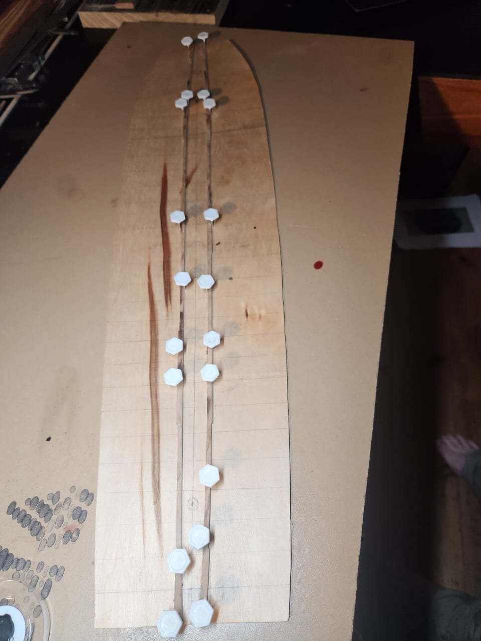
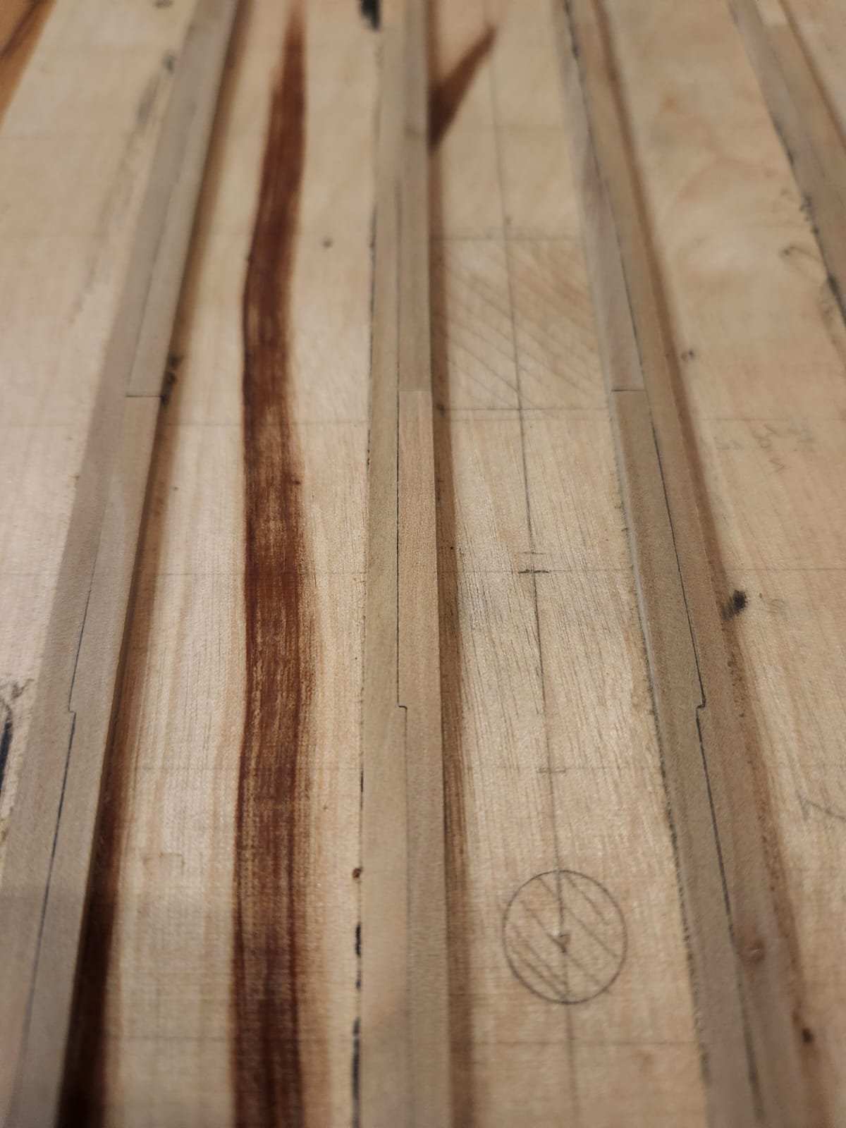
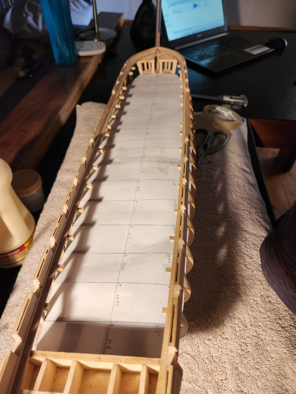
Hello All, I haven't achieved a huge amount due to work pressure, but I wanted to give a little update so that I don't fall too far behind again. As said before I decided to put in the gun deck so that I could show the vessel with guns visible and no port lids to try and remain true to her launch configuration. I began by measuring the distances between bulkheads and then again between bulkhead extensions and plotting them in Excel and on paper. The Excel was somewhat impractical because printing at the exact correct scale was almost impossible. I then reverted to the paper plan which I did in 2 pieces and taped together once they had been checked in place on the gun deck. I did do a small amount of faring of the internal bulkhead extensions, but this was pretty basic work as they will not be visible once the spar deck is in place. I then fitted this on the bulkheads to ensure that the plan was close enough to be acceptable under the circumstances. This plan was then taped to a sheet of 0.5mm plywood which was cut to size and checked for fit.. Once this had been checked I started the layout by marking the center line and then checking the location of the kit positions for the masts against the Waldo deck plans from 1819 as shown below. I found them to be close enough that moving them seemed to be unnecessary. It appears that the model shipways plan was perhaps based directly on this Waldo deck plans or rather the deck plan is close enough to the current state that it fits well. I used this layout as the plan for the hatch locations and initially marked only the hatches which I thought would be visible from above, but I think I will ultimately put all the hatches and fittings on the deck in case they can be seen from some strange angle. IN addition, I marked out the beam locations more or less as per the Waldo plans which some minor adjustments. The final marks made were the slightly curved line marking the inner edge of the inner set of joggled thick strakes. As per Joshua Humphrey's document on dimensions and sizes of materials for building a frigate of 44 guns drafted in 1794. This essentially meant that the lines were marked immediately next to the widest of the hatchways and then gradually curved toward the centreline at the bow and stern. It is hard to see the pencil line, but I assure you it is there. The run of the next strakes will be laid out once these are done The matter of the dimensions of these thicker joggled strakes is one that has lead to a huge amount of head scratching. As in the text above the instruction is to use a plank not thinner than 10 inches and that is about all we have for instructions. This in itself causes issues, but I am assuming he means not thinner than 10 inches at the narrowest point. A second issue is how long were these strakes. Tyron G. Martin (mentioned in previous posts) says that the "C" of the strakes was 40ft long in one of his versions of "Close up". Neither MarcusK (who has been a bottomless pit of knowledge) nor myself can figure out where he got this information from. A 40ft "C" would result in a plank 80 foot long. Research into the white oak trees that were used for this piece of timber tells me that it is theoretically possible as the tallest white oak recorded reached some 200ft. That being said I do have some concerns about finding 16 runs of flawless timber of this size and then the additional consideration of both transport and installation as well as future repairs with a spar deck above. The final consideration on these strakes is how many "C"s per plank. Martin's comments make it obvious that only a single "C" per plank is possible and by making use of a single "C" construction would be far easier. I cannot really find much more on the subject, but I can point to a photo of a modern repair in progress which shows multiple notches on this strake (it obviously has limited value but seems worth sharing.) Taking all this into consideration I opted to go with planks with a single "C" that would scale up to a total length of +-40ft. This was mostly because I really struggled to find straight runs of pear trees longer than 32cm as the trees I'm using were grown for fruit so they are heavily branched from very low on the trunk. I also decided to make the narrowest part of the plank scale to 10 inches. this left me with a plank of 158mm in length with a +-79mm "C" notch and +-39mm shoulder. The planks are 4.25mm at their widest point and 3.4mm at their narrowest part. I made a set of 16 of standard dimensions shown below. These will be tidied u and straightened as they are fitted. Please excuse the burn marks, the table saw blade clearly needs a clean. the remaining 16 will be cut to fit into these once they are in place. That's all for now. Be good TBE

.thumb.jpeg.c8d294f76ba1d0a959637dddce15814b.jpeg)
.thumb.jpeg.93a457884c8c6be3166ce1991e79af7c.jpeg)


- 193 replies
-
- 11
-
-

-
- Model Shipways
- constitution
- (and 5 more)
-
Thank you Jon, these are great!
-
Absolutely! that would be a great help, thank you
-
I believe you are right on all of the above. I am going to look into a number of options for accurate cannon. Marcus has given me dimensions for some of the cannon, and I am going to try to turn them on my lathe. I don't know how well this is going to go, my lathe options are a tiny, somewhat underpowered unimat3 and a Colchester with a 2-meter bed and a chuck that weighs more than 1000 of these canon will. so Neither is idea.. Thank you very much for the tip on Mustafa friend and syren, I will contact both.
-
I know 😂 It is crazy. My thinking is that the kit is so bashed so far that it might as well be a scratch build anyway(I actually regret not just cutting the bulkheads and false keel myself, they are the only parts I have made use of from the kit. A little extra bashing shouldnt hurt. Also I did consider doing as you said and showing her with her gun ports closed but I felt it would have taken away from the feeling of her as a fighting ship and taken away from another little piece of information about her(her armament when she was launched). I am sure I will live to regret this as I now have to somehow make or buy her cannon but we will see what happens. Haiko
- 193 replies
-
- 2
-
-
- Model Shipways
- constitution
- (and 5 more)
-
Thank you to everyone who commented here. Lots to learn as always. It's great to see all this experience and knowledge laid out so eloquently. I think each and very perspective is certainly plausible: 1. The tops were not the tops as we see them but rather the upper part of the bulwark 2. The hammocks were intended to protect the dead eyes 3. The hammocks did in fact go into the tops and were perhaps hidden behind canvass covers or wooden structures 4. The hammocks went into the tops and were just stacked without any sort of additional structure. I will continue to look into this and I look forward to any additional gems that you gentlemen find. Kind regards Haiko
-
I really hope you can recall the source. To me it really made a decent amount of sense. If I had the option available I would certainly want to make use of it. If it's good enough for the boys on decks it would be good enough for me. Haiko
-
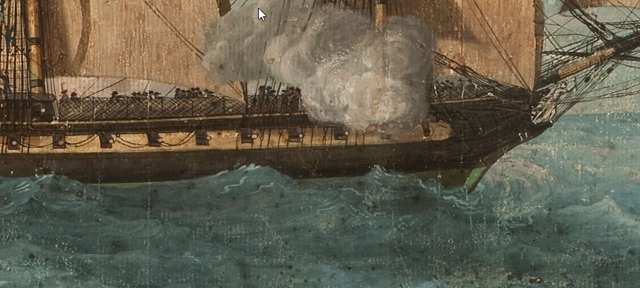
I noticed the same red structures in many of the paintings I looked at. That in itself is a little unusual, and I would love to know the origin of that colour choice. I really hope you find the painting you were looking for. It also occurs to me that these artists would very rarely, if ever, see ships in actual battle. These paintings would have been based on what would have been seen when the ships were in port or at anchor. That may explain the absence of a feature which is only mentioned in the context of beating to quarters. Haiko
-
Hi Gaffrig I thought this might be the case too so I looked at a nautical glossary from the period and I could find no other definition besides the standard fighting tops. I also think it would be an unusual turn of phrase because he says in the netting and the tops. I think the netting would be a reference to the netting on the rails? This is all speculation and you might be right that it was infact a reference to the tops of the stern bulwarks and the netting was a reference to the netting in the waist? A mystery indeed! Haiko
-
Hi Marcus I guess you are right on this. I am familiar with the rails, I had just not seen them covered with canvas before and I assumed that was just the same kind of canvas we would have seen in a deck level hammock crane. I guess I need to do some more digging. Cheers Haiko
-
Hi there Thank you for your response. This is a great suggestion and I think I may have found something which looks like it could potentially be what I was looking for. https://upload.wikimedia.org/wikipedia/commons/f/f5/Thomas_Whitcombe_-_HMS_Crescent%2C_under_the_command_of_Captain_James_Saumarez%2C_capturing_the_French_frigate_Réunion_off_Cherbourg%2C_20_October_1793_CSK_2017.jpg Please let me know if you find anything else which might contribute. TBE
-
Hello to everyone interested in a most obscure of nautical questions. I am busy building the USS constitution, and this has lead me into some fairly interesting reading and discussions(particularly with @Marcus.K. who suggested I ask for input from the forum)In this process I found an extract from the diary of Midshipman James Pity where he makes the following statement: 31 Aug 1798 - "Beat to Quarters and Stow'd our hammocks in the Nettings and in the Tops and fill'd our Lockers with Shot..." Is this gentleman telling us that they stowed hammocks in the fighting tops? I don't think it's the most outrageous Idea, hauling things into the tops would have been pretty standard behaviour and there is the advantage of potentially providing cover for the marines stationed in these tops, but I cannot find any other references to this being done or any evidence for stowing locations. Does anyone here have and info on this or evidence to support the idea. Alternatively, is there another explanation for what our friend here meant by "tops"? Thanks! Haiko
-
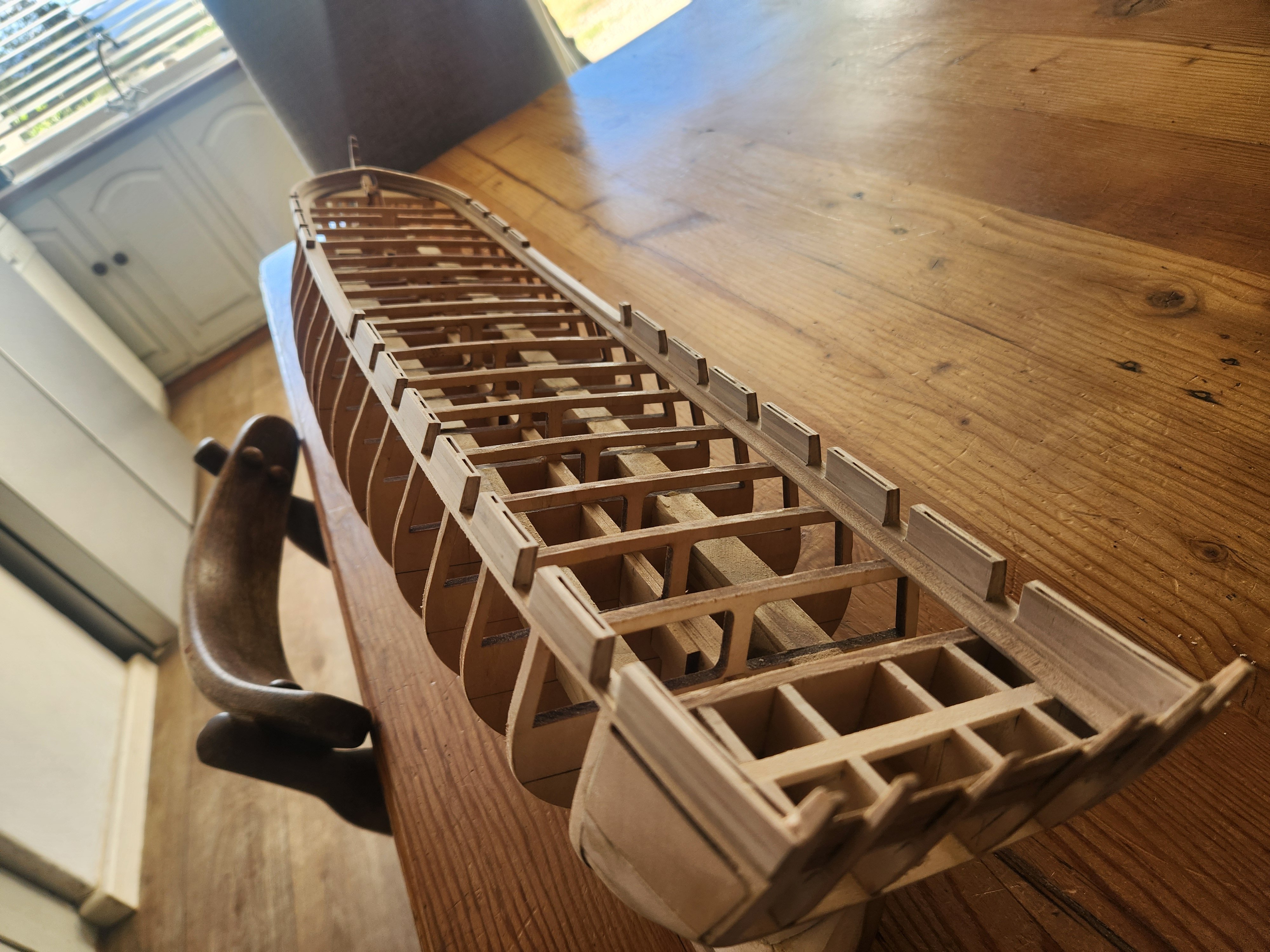
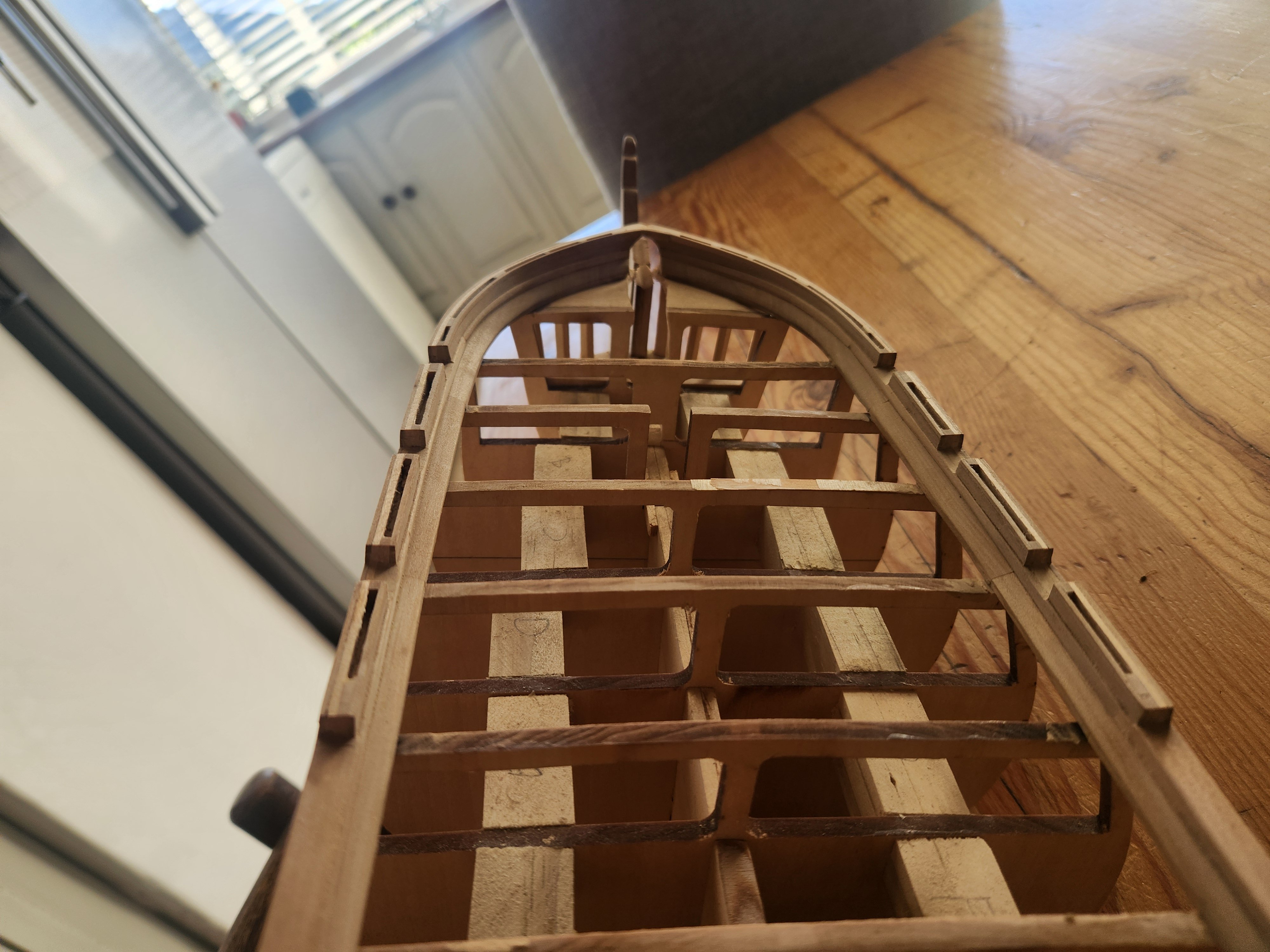
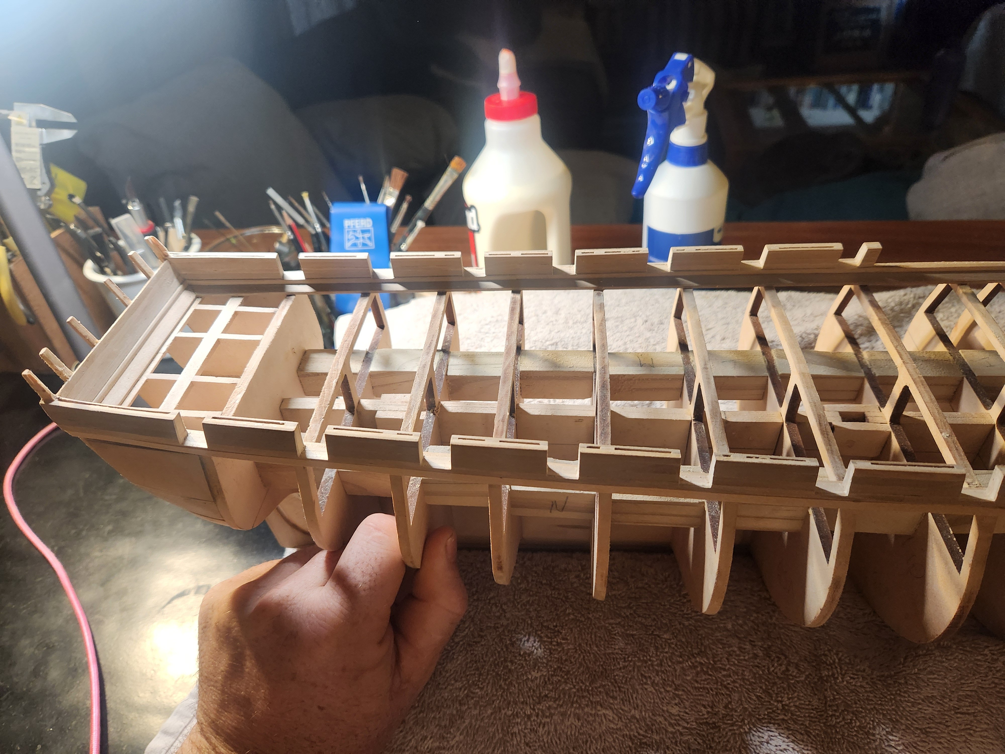
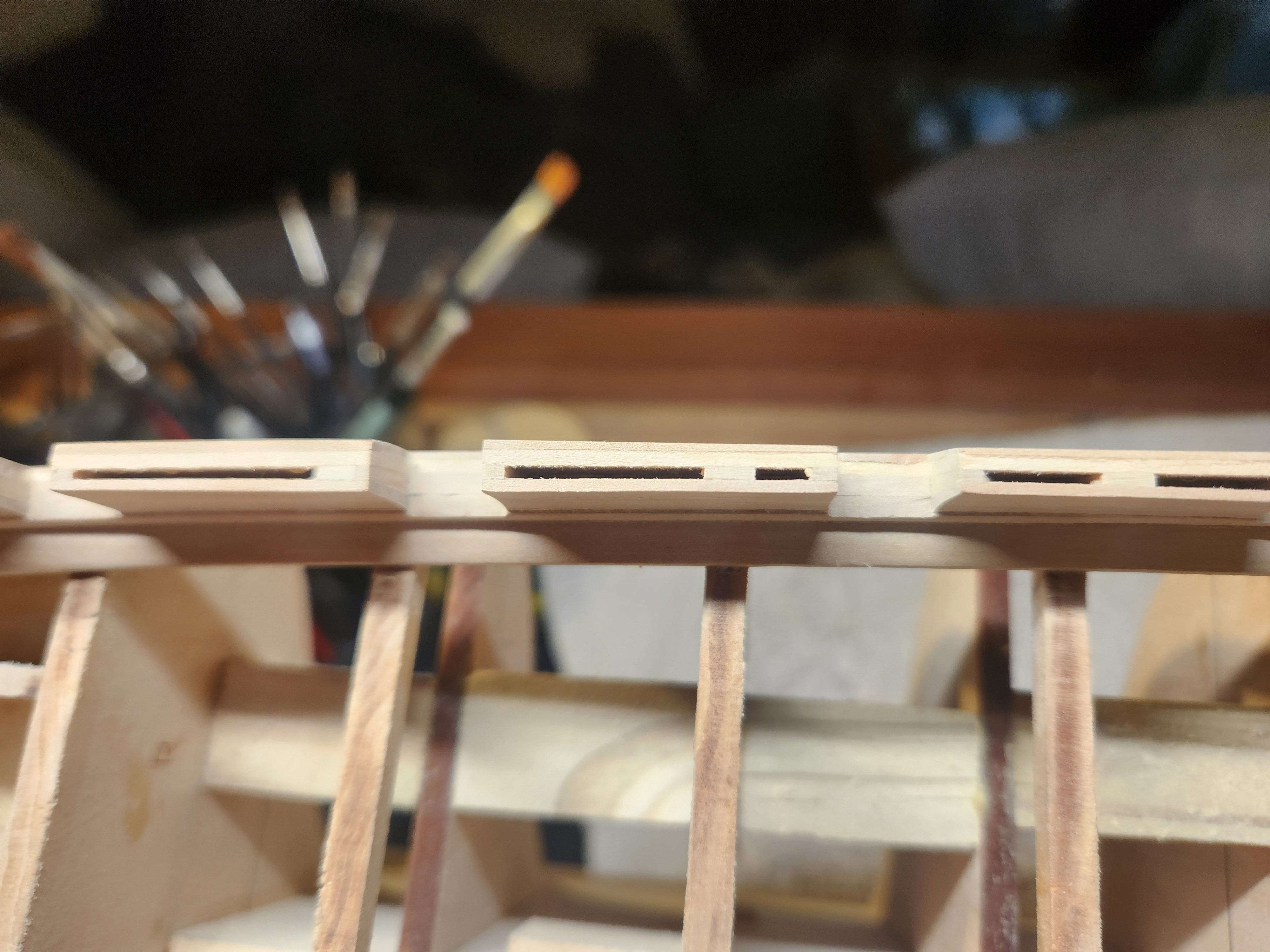
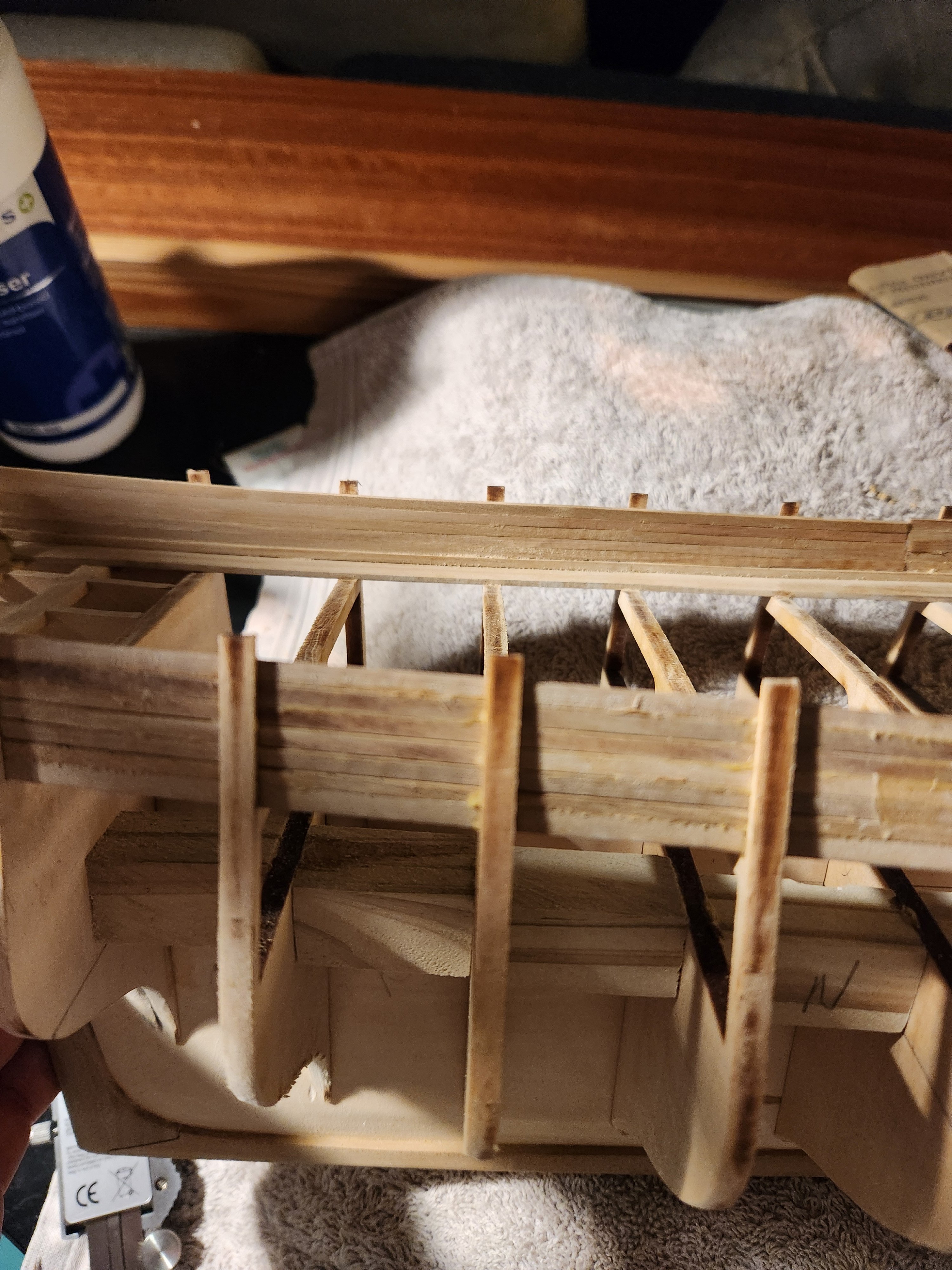
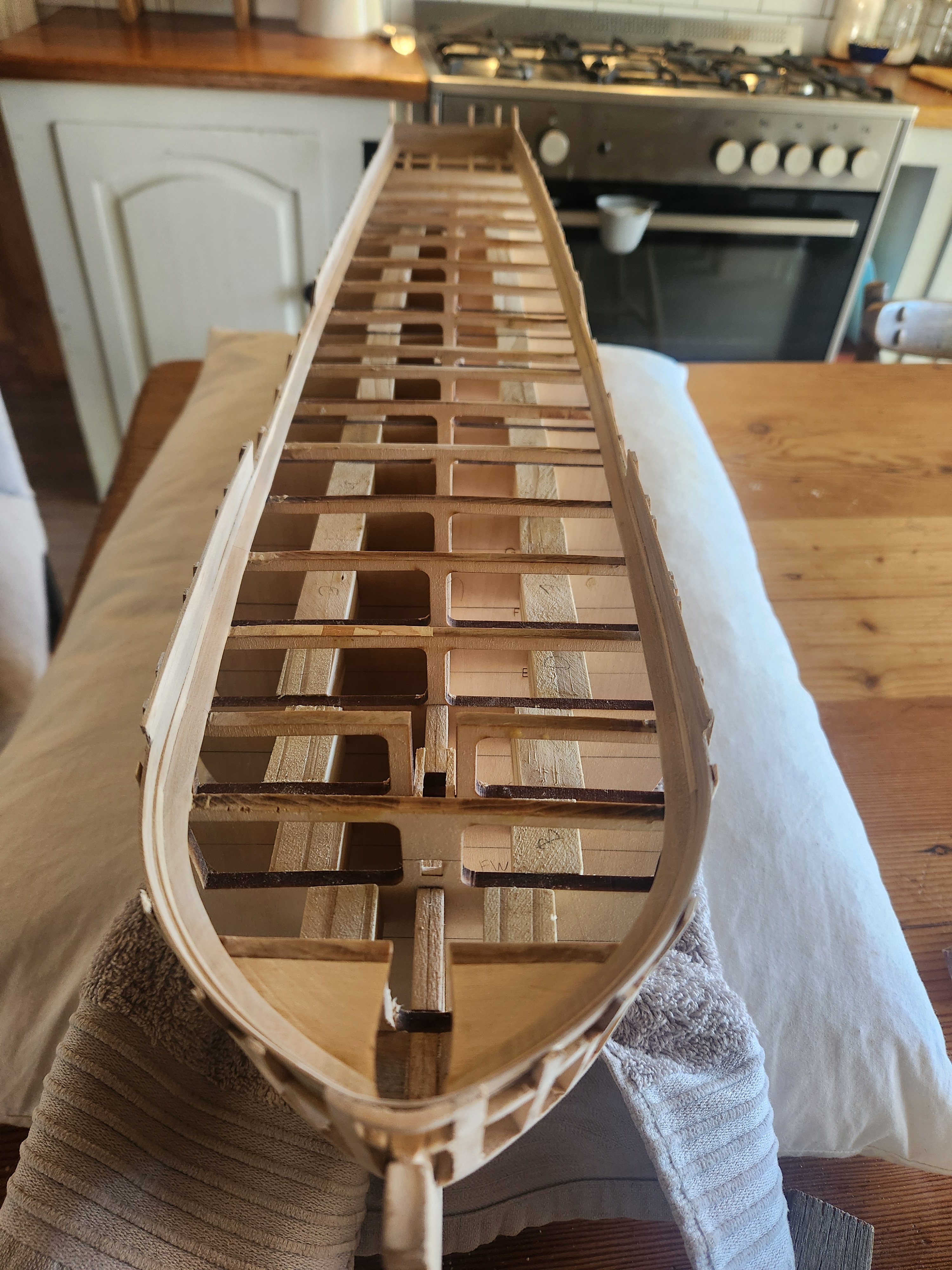
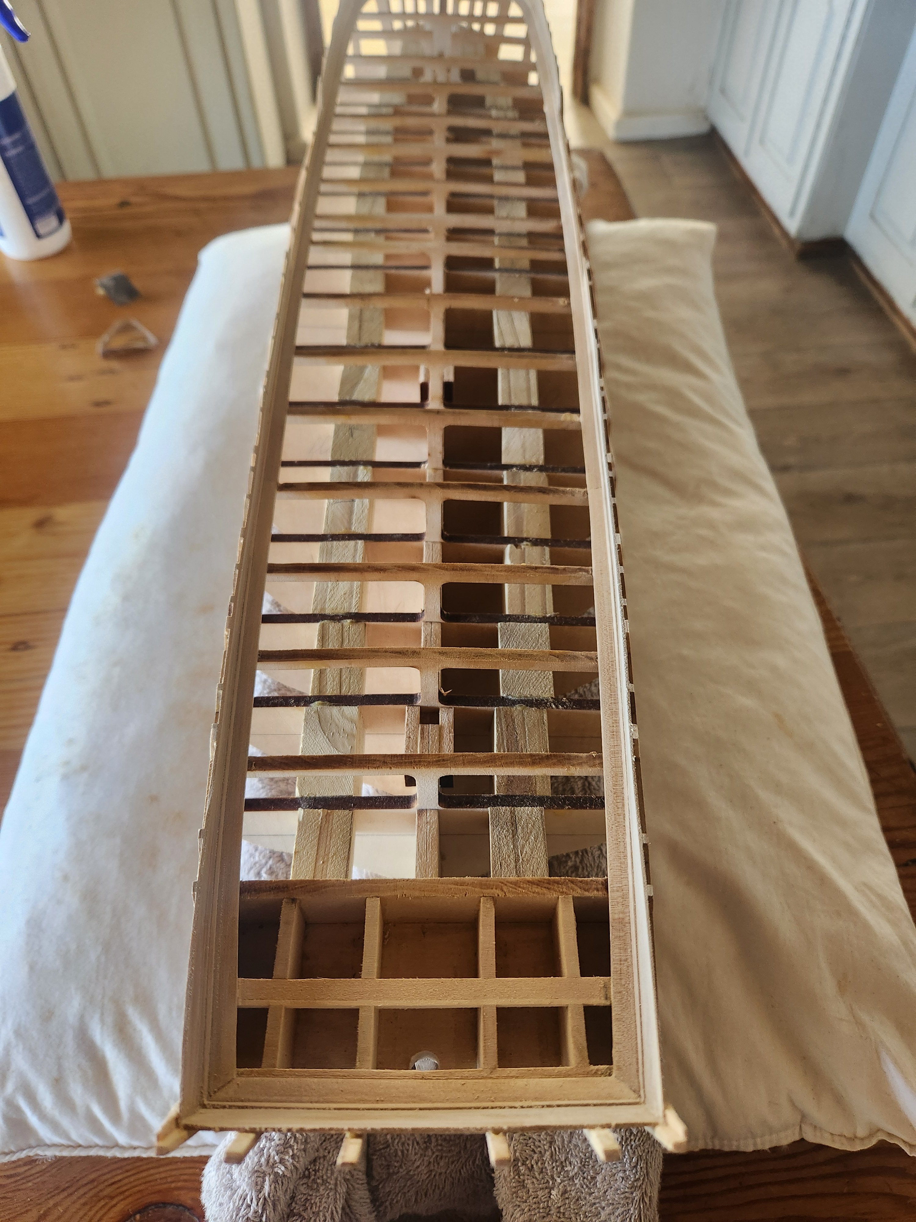
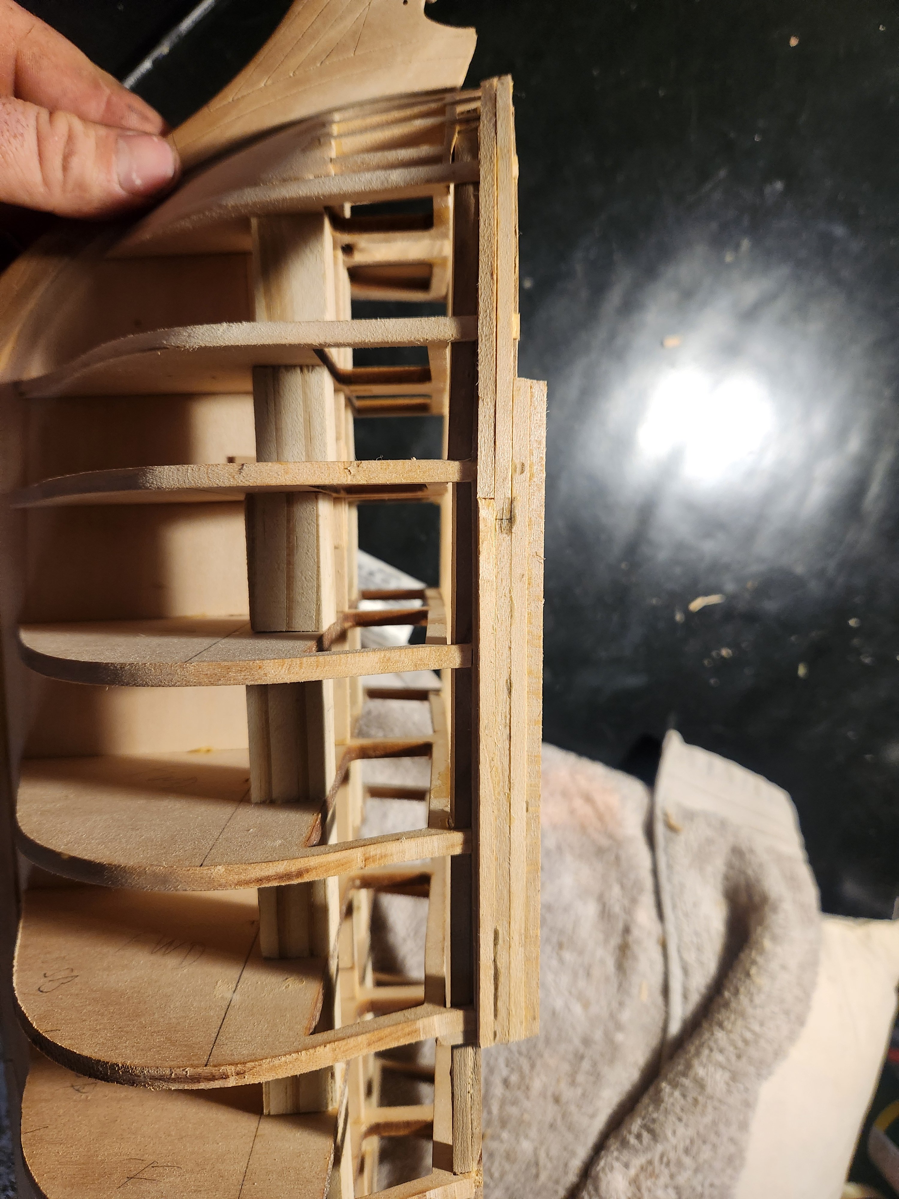
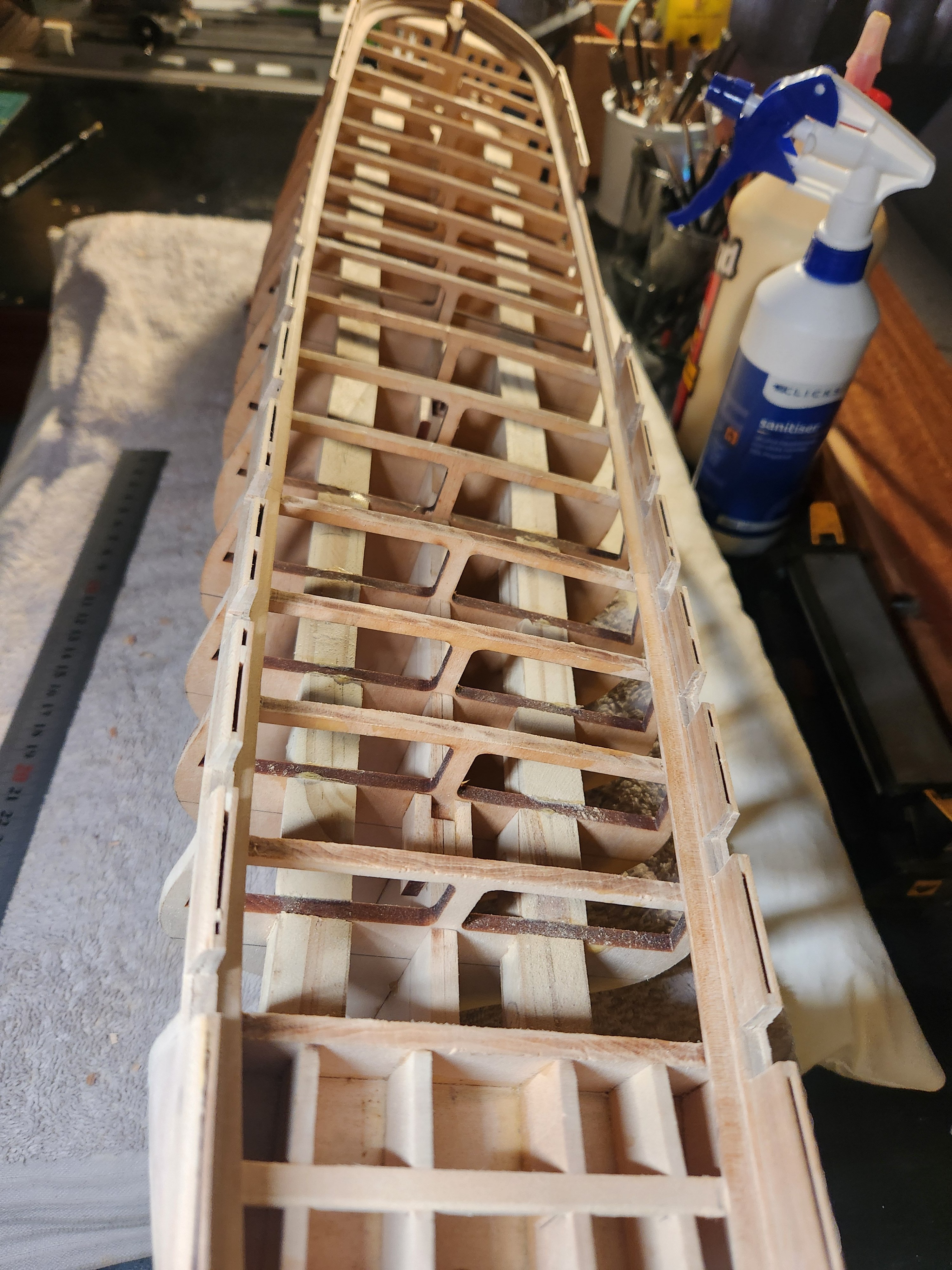
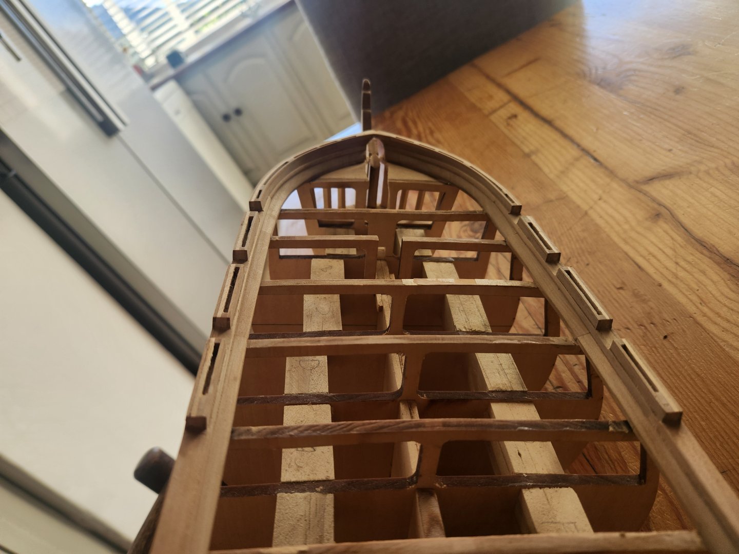
Last post for today. Originally, I planned to show the model with split and closed gun ports. Research (and Marcus) have told me that the gun deck probably didn't have gun port lids when she was first launched. Or rather had fully removable lids instead of the split lids provided in the kit. This means that if I wish to show her guns (open lids) then I need to do a gun deck of sorts inside. I will probably do a fairly basic deck that only shows the details that will be visible when the model is complete, but we shall see. Regardless, this means that I need to now install a gun deck at this very awkward stage. My solution for this was to glue 5x5mm alignment blocks on the bulkhead deck beams with a small spot of glue so that if I cut the deck beams they could be used as reference points for reinstalling the beams later. Once these were glued in, I cut the beams with a Stanley knife blade and cut the vertical support with a dremel. This opened the space for gun deck installation. Unfortunately, when I put my bracing blocks between the bulkheads I hadn't planned to do a gun deck and the work was a bit sloppy, so I butchered out the blocks where they protruded above deck level. Not a pretty result, but they will be hidden under the deck TBE
- 193 replies
-
- 8
-
-
- Model Shipways
- constitution
- (and 5 more)
-
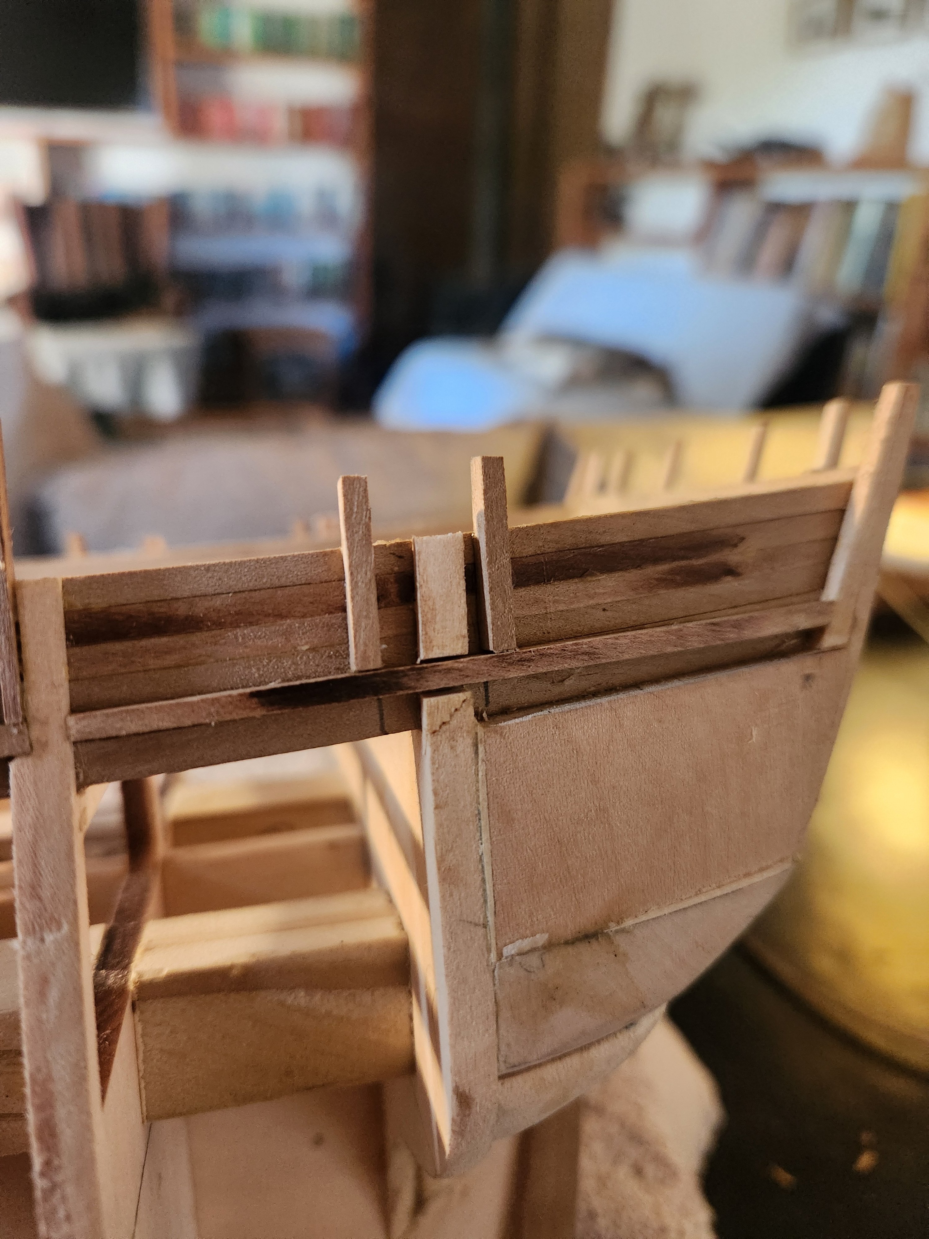
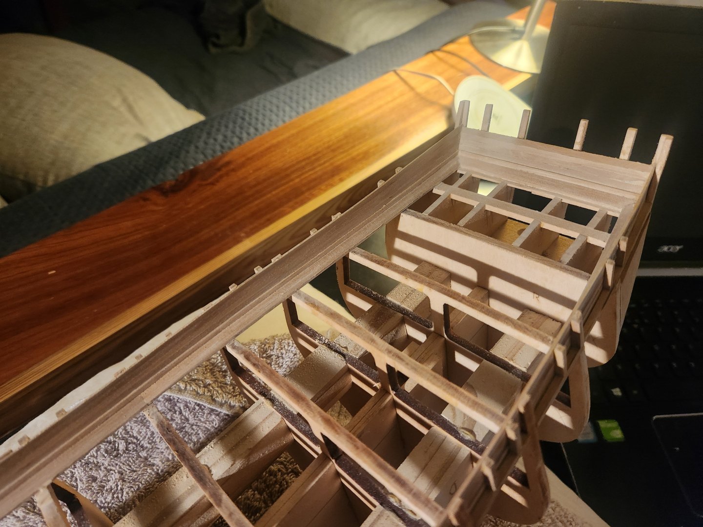
Two quick posts coming up. This is the approach I went with for the capping rail for the waist. I made it wide enough that it sits flush with the outer planking and thick enough that it is the same height as the plankshear which I cut out and replaced. I don't know that I love the appearance of it, but I had to choose between having the cap not align with the plankshear or having a thick cap. Furthermore, I suspect that the dimensions given for the plankshear on the model shipways plans are a bit too big(I would make it narrower f I started again). I am very much open to suggestions on how to improve this. I can easily remove and redo it. TBE
- 193 replies
-
- 2
-
-
- Model Shipways
- constitution
- (and 5 more)
-
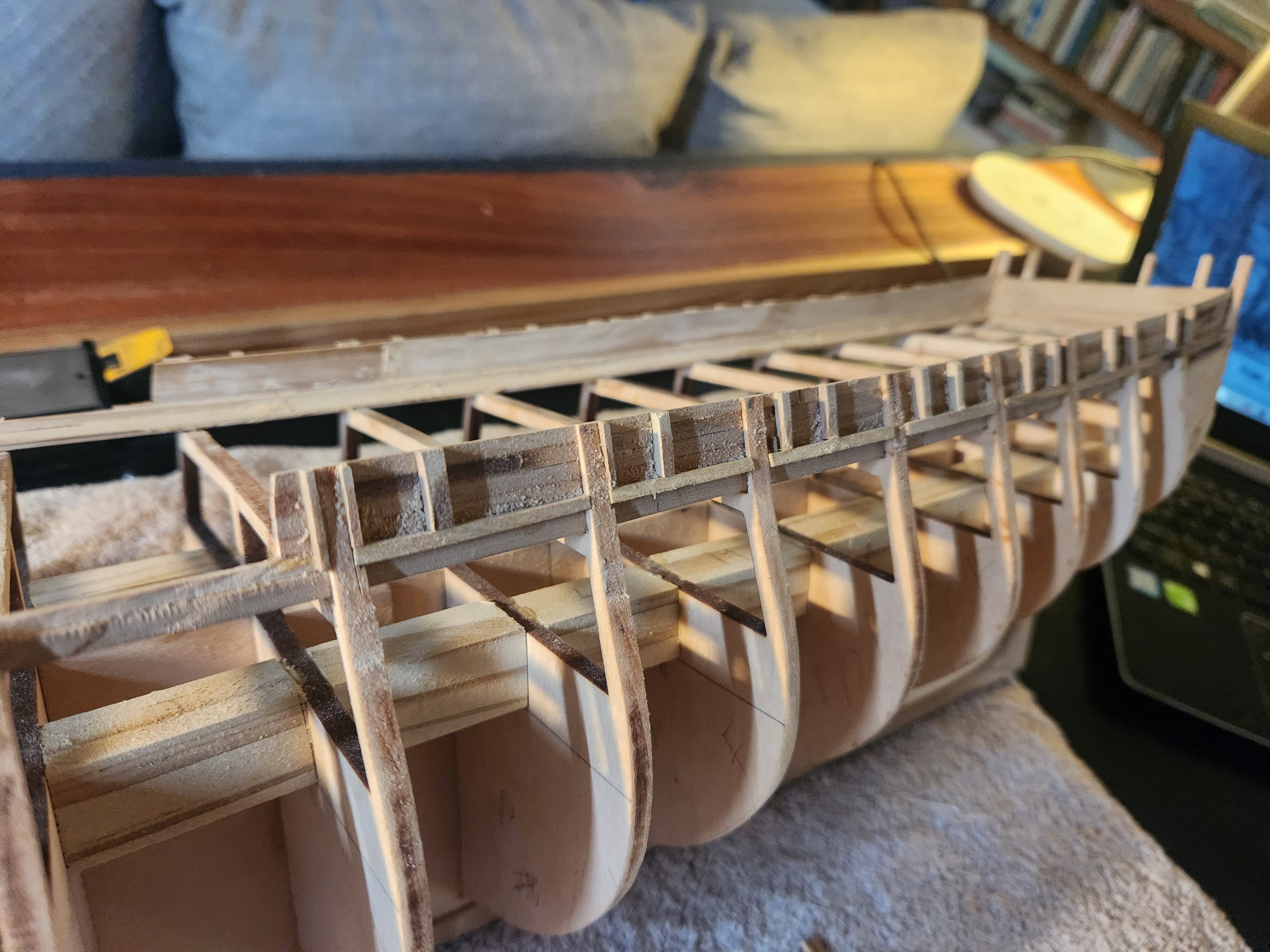
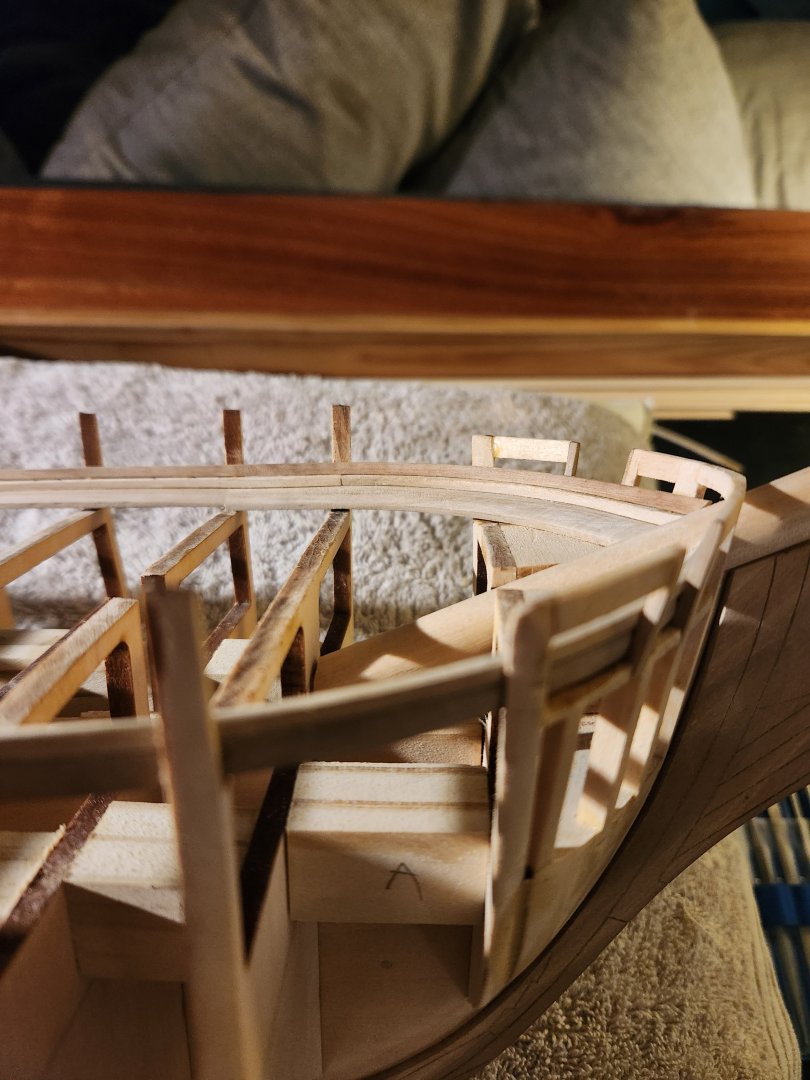
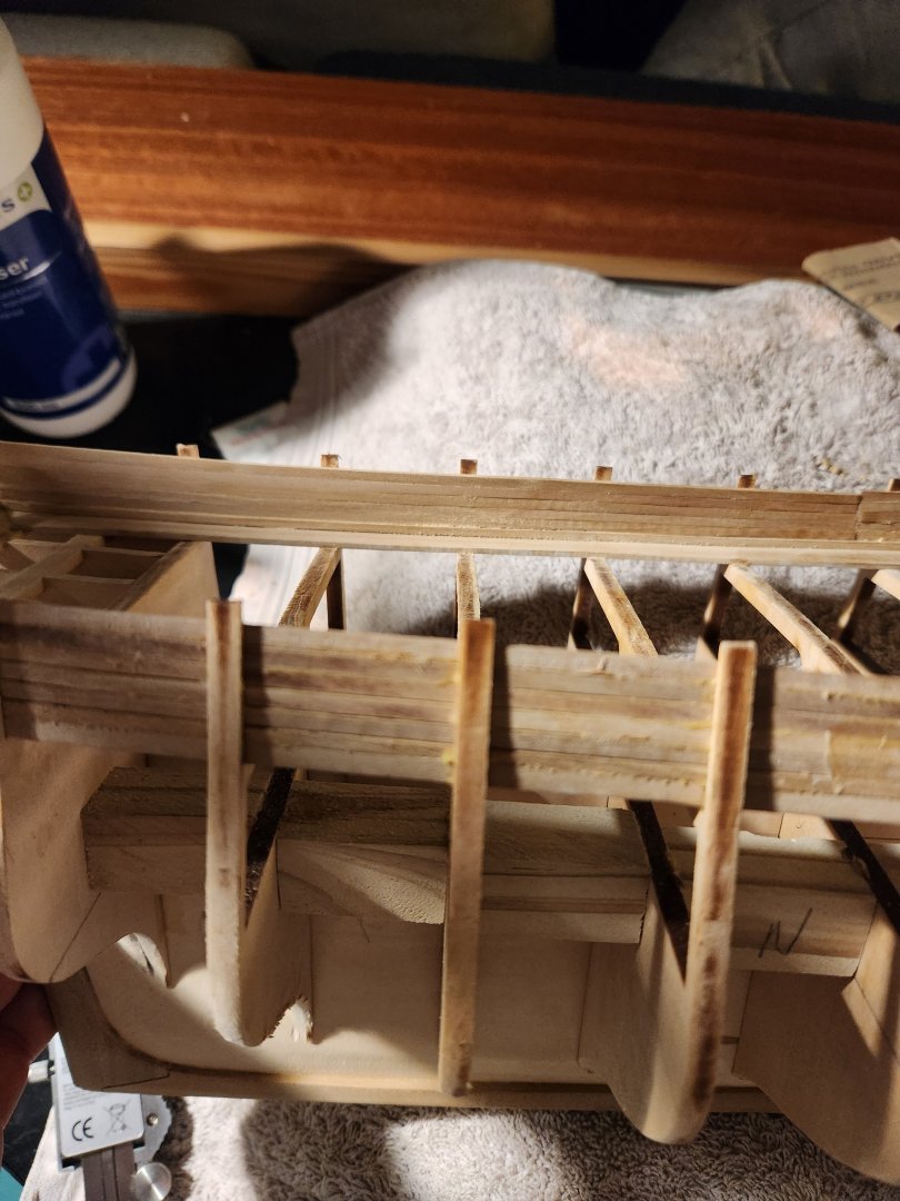
Continued from post 94: final spar deck bulwark layout sanded and complete.


- 193 replies
-
- 8
-
-
- Model Shipways
- constitution
- (and 5 more)
-
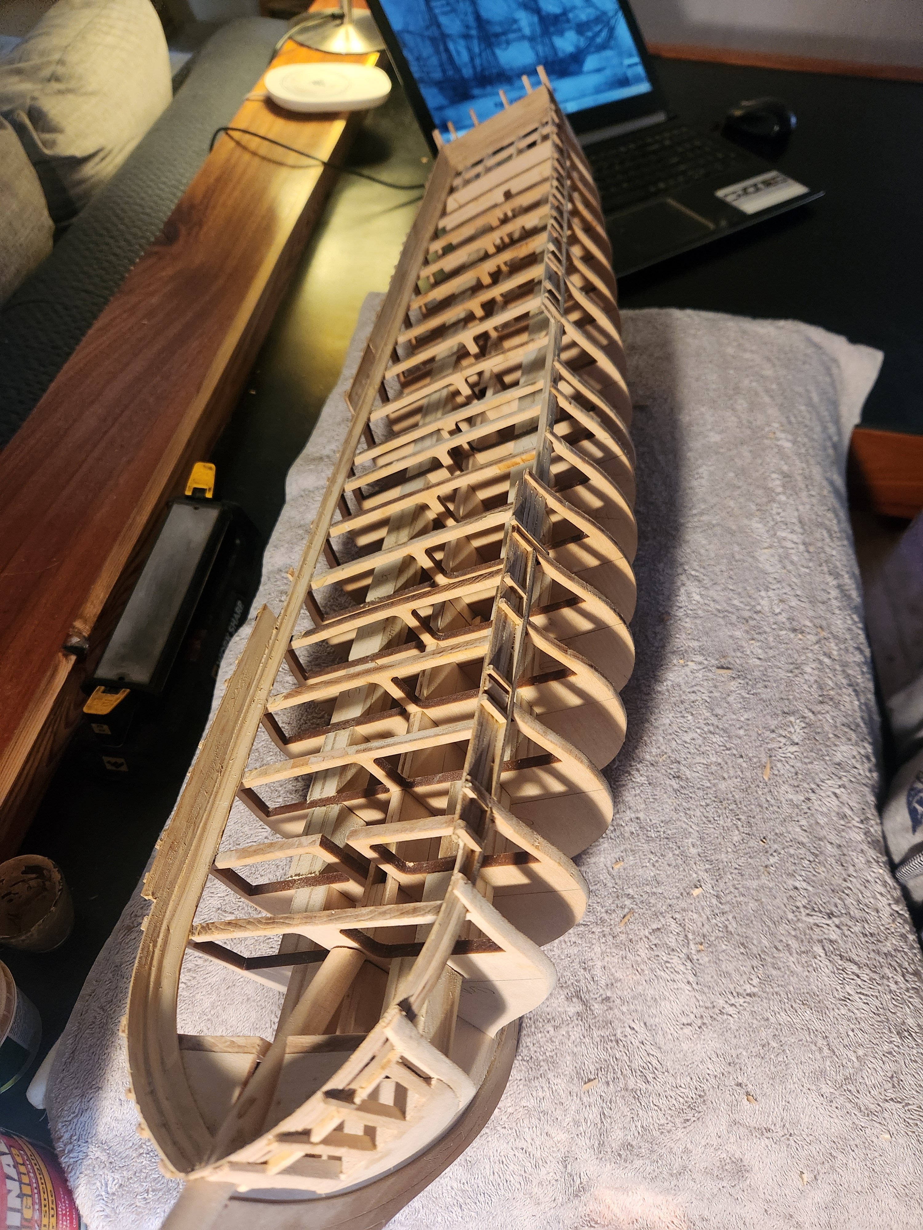
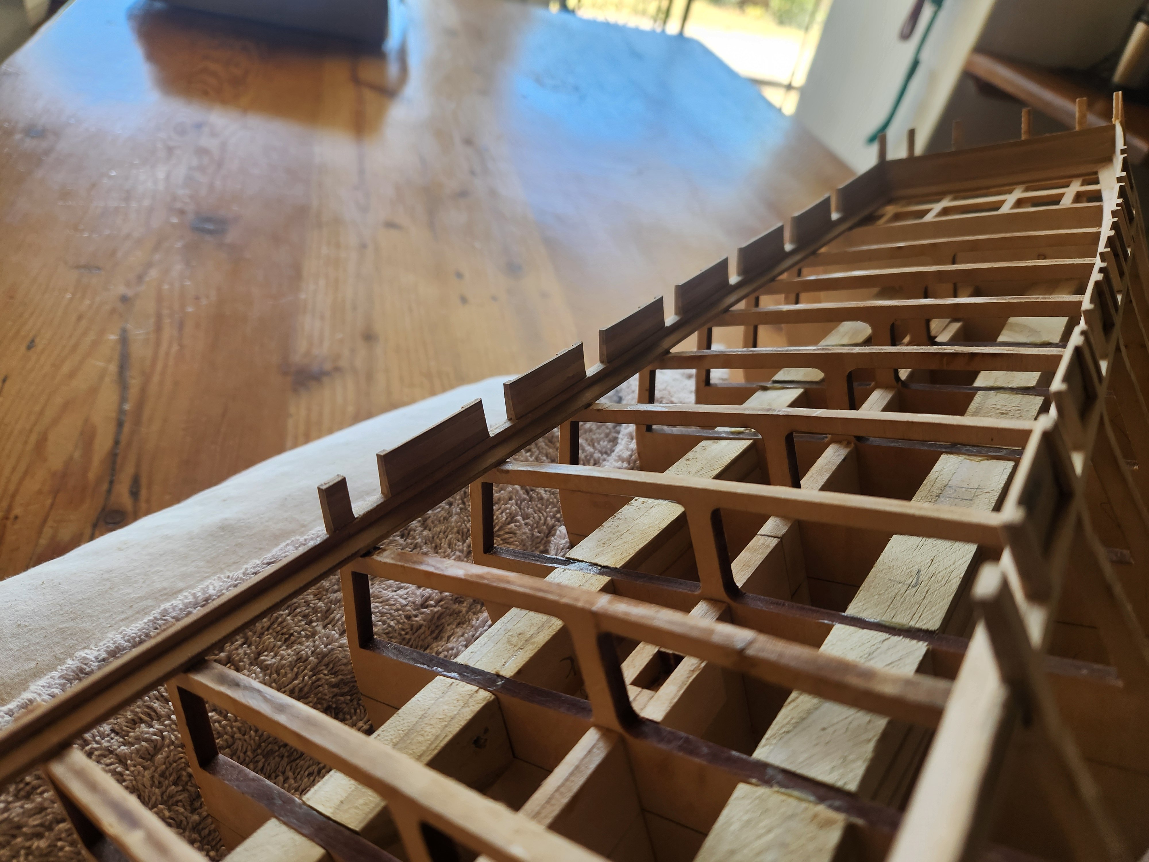
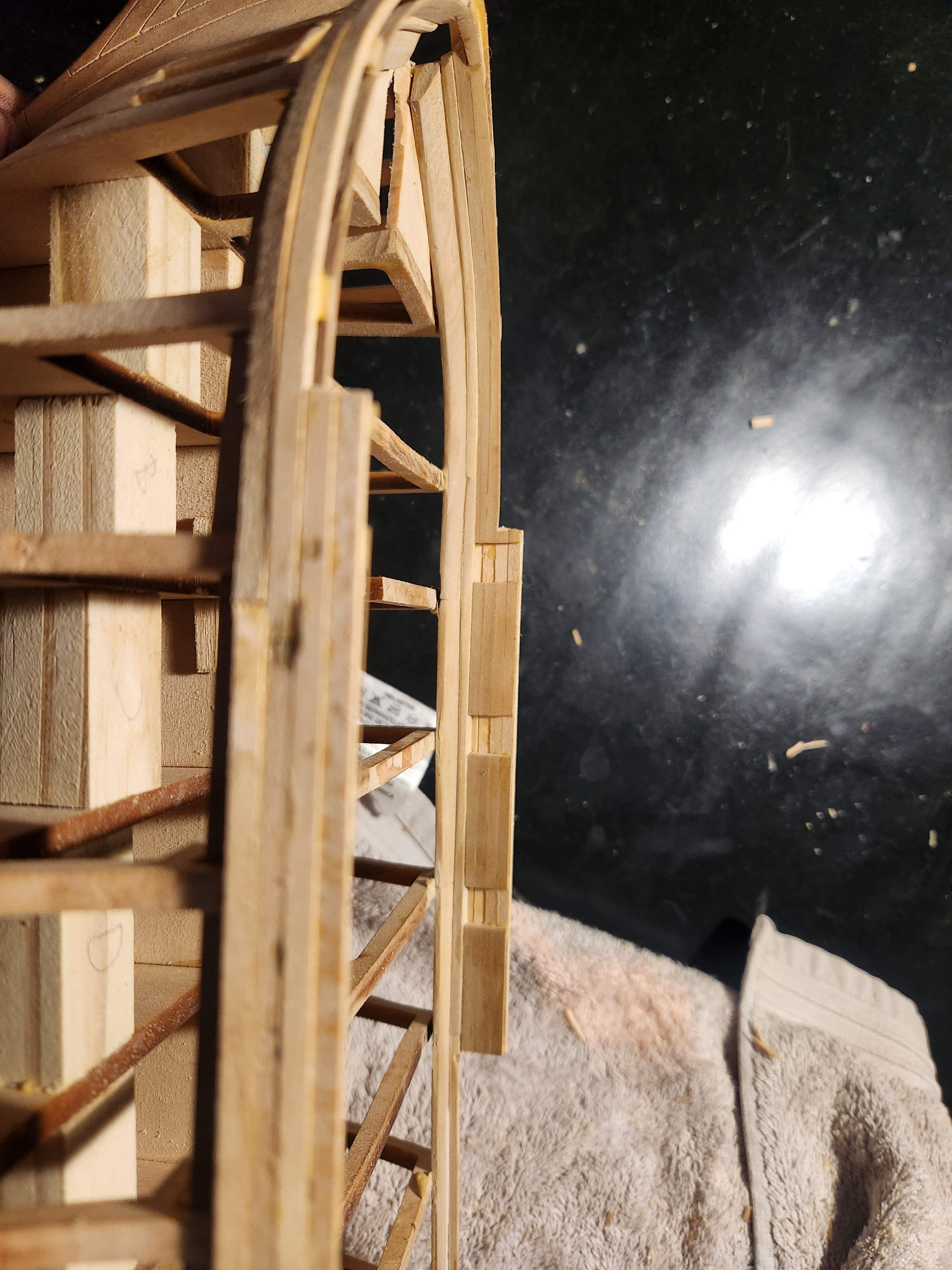
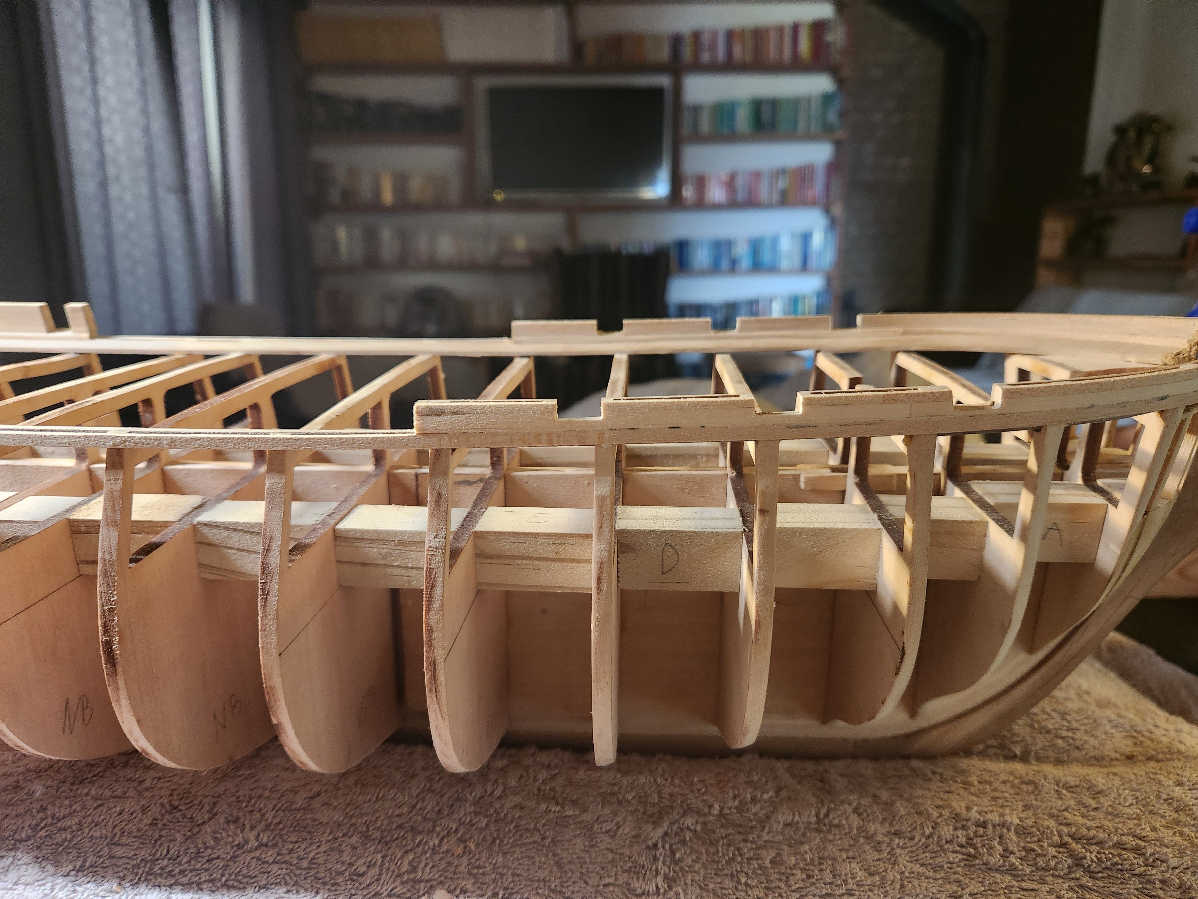
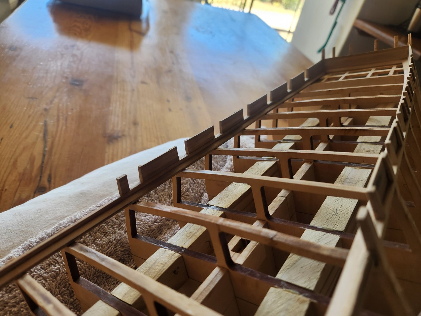
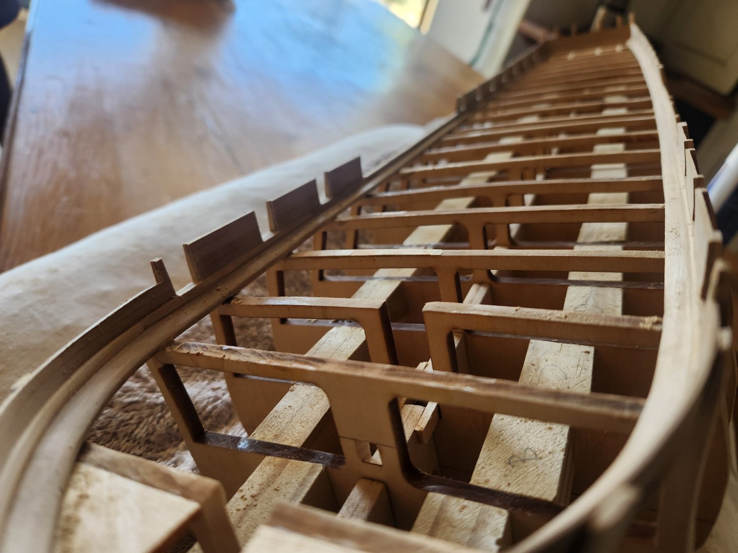
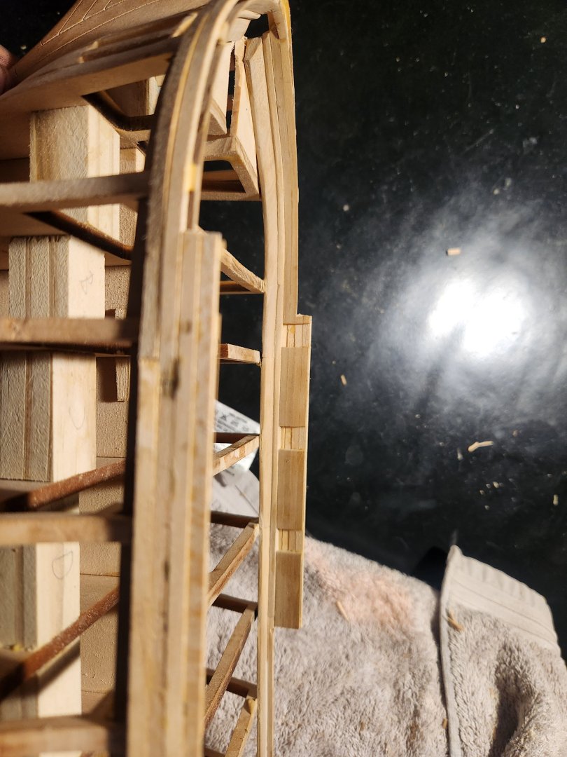
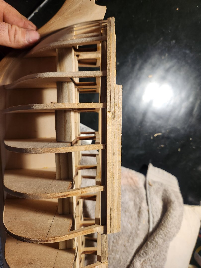
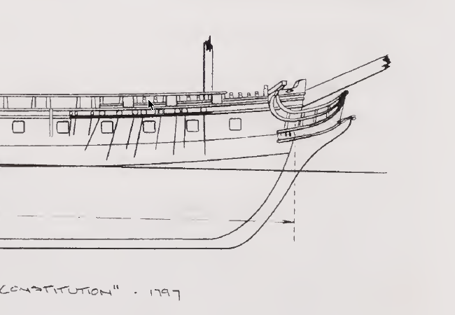
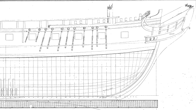
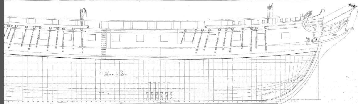
Hello Boys and Girls! After a long delay due to the festive season, harvesting and research, I finally have some time for a bit of an update. I have been having some very interesting conversations with the very kind and well-informed, @Marcus.K.and he has inspired me to really go with a model that is as close to the 1797 launch design as possible. This of course brings up a whole array of challenges and questions, but I have found it adds an element to the model that I am really enjoying. I will try to justify my choices as much as possible as I post here. If anyone is interested in further detail, please let me know. Marcus is being as patient and helpful as any human could be, and I look forward to building a model that both of us can be happy with. I welcome any and all input on choices made here, both historical and practical. To the build. Having completed the plankshear I began the bulwark component. I settled quite early on a layout with 20 gun ports on the spar deck, as per the Doughty drawing (Humphrey's). I felt fairly happy with this choice as it matches both the earliest drawings from 1794 and the paintings of Corne from 1803. Looking at the repair record of the 1801 shipyard, there is no mention of moving gun ports, so I am more than happy with this configuration. I got the gun port and waist spacing by scaling up the doughty drawing and converted the measurements. I can give the exact distances to anyone who happens to care. Initially I also opted for a raised stern bulwark (as reflected in the corne paintings), an open waist and a slightly raised section forward of the waist followed by an open forecastle with just a 2 plank bulwark(+-40cm at full size). I achieved this by first planking the inner bulwark with 4 strakes of 2.8mm pear planking. I ended up needing to have joints in the planks because of the limitations of the material I am using, but I simply made sure that this joint fell on a gun port so would be cut away at a later stage. Once these had been installed, I trimmed back the bulwark extensions. Then realised I had actually put in too many strakes. Removed a strake and roughly sanded the planking back. I then put a thin film of wood filler over the whole area and redid final sanding. I find it is best to do this sanding before bringing the bulwarks to height or length to prevent rounding of the edges. At this point, I also rounded over the plankshear slightly to create a more natural finish. Next was to add the gun ports as per the doughty measurements. This was done by measuring and marking from the stern forward. This resulted in gun ports landing over bulkhead extensions. To remedy this, I first cut away a narrow slot in the extension so that I could install the horizontal gun port beam at the level of the plankshear while the extension still held the upper portion of the internal bulwark in place. I then added the 2 vertical parts of the gun port opening. Then I did this I only worried about the visible faces of the framing, which also meant in certain cases the bulkhead extensions needed to be trimmed back and faced with pear wood so that only the pear wood would be visible when the gun port was complete. The rest would be hidden by the outer bulwark planking and the thickness would be corrected during faring. These framing pieces were then fared back so that once the two additional layers of planking were in place, the top of the bulwark would be 5mm thick to match the correct dimensions of the ship (21 inches at deck level and 15 inches at the top of the bulwark.) I then began cutting out the gun ports. I did this by using a jewelers saw to cut a small relief slot down the centre of each gun port and then clipping back the excess until it was almost flush with the gun port frame. Furthermore, I then used a scalpel, sanding stick and files to square everything off. Next up was installing the 4 lime wood strakes on the outside of the bulkhead extensions. This had to be done as I am double planking this hull, but I actually made a mistake here. This method resulted in a thin strip of lime wood being visible inside the gun ports, but I can live with that. The procedure was the same as above...glue on planks, rough sand, wood fill, final sanding then cutting out the gun ports... I added one additional strake below the bulwark to help with the alignment of the waist capping rail. At this point in my discussions with Marcus, I felt that I needed to make a change to my layout choices. It appears that the vessel probably had lowered bulwarks from the waist forward. I say this for a number of reasons. 1. The Gillmer drawing (based on the doughty drawing) shows a low bulwark and rail forward of the waist - From Old Ironsides -the rise, decline, and resurrection -Thomas Charles Gillmer 2. The doughty drawing (available on the USS constitution museum website) shows a raised section forward of the waist but just a bit lower. That being said he also shows a far lower bulwark in the stern which seems to have been raised in the building in my opinion as the stern bulwark is raised in the corne paintings, but there is no record of the bulwark being raised during the 1801 refit, although it is possible (as Marcus pointed out) that this was simply done at sea without any mention because it is essentially a simple task to clad the railings 3. Tyrone martin is adamant that the bulwark was open forward of the waist and closed in the stern. I cannot imagine that he would have made these very specific changes to the doughty plan without good reason - Mentioned in "Constitution - Close up - Tyrone G. Martin" and "Tyrone G. Martin - A Most Fortunate Ship - A Narrative History of Old Ironsides" and again quoted below in "The Artist, the Historian, and the USS "Constitution" - William Gilkerson, Tyrone G. Martin" 4. The corne painting appears to show an open bulwark forward with hammock netting. "Michele Felice Corné - 1803 This resulted in me cutting back the bulwark once the second planking had been done and ending up with this final layout. I wish I had realised that I preferred this configuration earlier, but there is nothing a little steam can't fix.: The final layer of planking was added, sanded filled and cut back with this as the result.(See next post) TTBE


- 193 replies
-
- 5
-
-
- Model Shipways
- constitution
- (and 5 more)
-
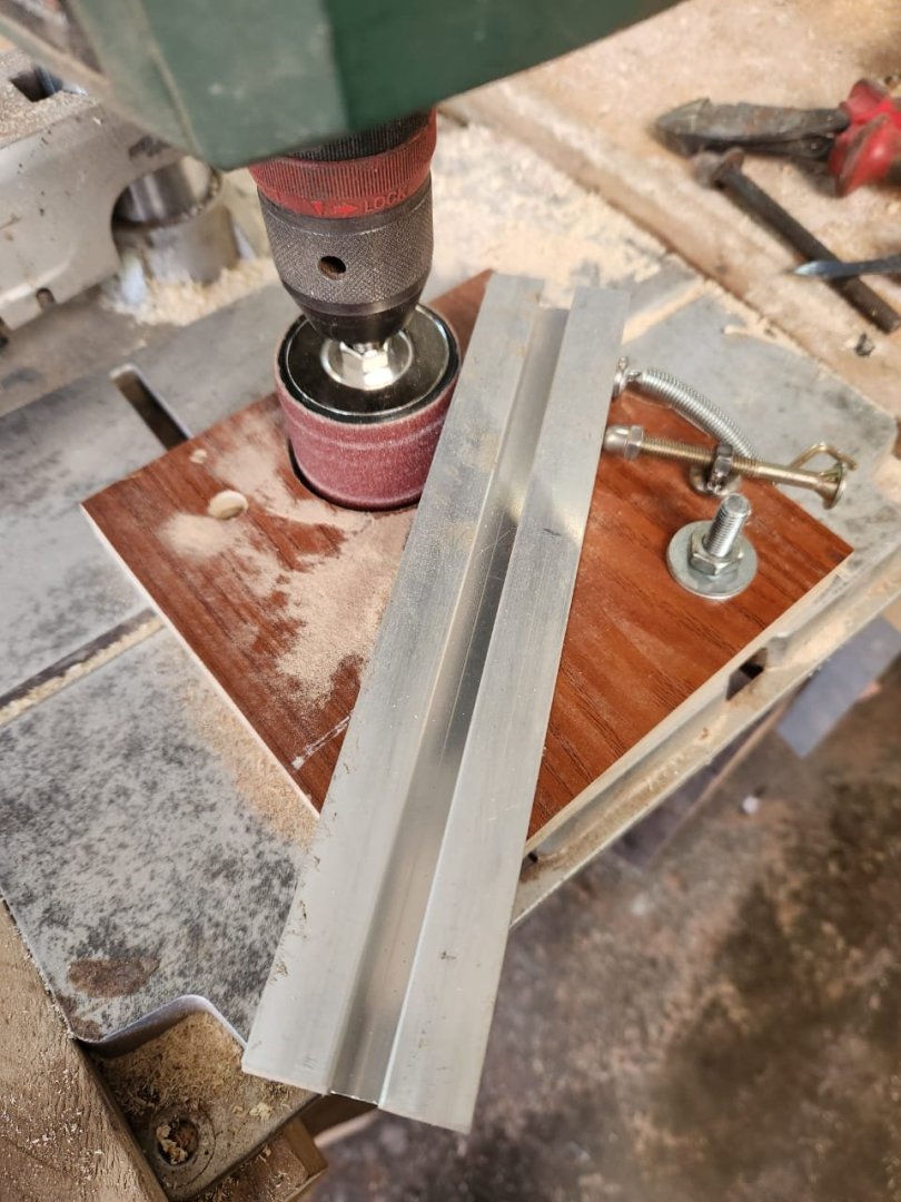
Thanks to some additional inspiration by @Der Alte Rentner and some research, I finally came up with a design for a thicknesser of sorts. It's mostly from a design stolen from this site with some slight modifications. Essentially just a board with a piece of aluminium channel on a pivot point bolted to my drill press. I added a set screw and a tension spring, and the results are surprisingly consistent and neat. It's not quite a Byrnes, but it's a hang of a lot better than doing it by hand. TBE
- 193 replies
-
- 4
-
-
-
- Model Shipways
- constitution
- (and 5 more)
-
You make an excellent point. I guess in this case its all fantasy anyway because as you said everything would have been painted in reality. It probably makes the most sense to just do what looks best to the eye. TBE
- 193 replies
-
- 2
-
-
- Model Shipways
- constitution
- (and 5 more)
-
Good Morning Peter Thank you for your input, I think I will skip the caulking as per your suggestion. I had the exact same thought about caulking the hull planking as you did, it's a strange quirk in a way that everyone caulks the deck but nothing else. For all we know I will have to paint the hull regardless, but let us see. As for the use of the term gunnel, I should probably have checked the terminology, I worked in the oil and gas industry before I became a farmer, and we used the term gunnel, along with a lot of other vernaculars that would not have impressed my mother. I am continuing my search for a reasonably priced hobby drum sander, but it is roving to be a challenge. I even made an attachment for my belt sander that should in theory function like a thicknesser, but it grabs the piece of wood and shoots it past the belt before it can do much....very frustrating. Kind regards Haiko
-
Good Morning Jon A wealth of knowledge as always! It is a real pity that the Peabody photos are no longer available, I searched high and low myself. I will give all that you have sent me some serious thought and make a decision. I was thinking this morning that there cant be many models out there with more variation than the Constitution, I guess the nice part of that is the fact that it really forces you down the road of research and learning. Thanks again(and sorry for hijacking your peter) Haiko
-
That is a very complimentary question to ask, thank you! I am just a farmer, that means that a big part of my life involves making things. Out here I have to be the carpenter, mechanic, plumber, electrician, weather man and a thousand more things. I am not particularly goo at any of these tasks but they all help in some small way to keep me going. If you are interested this is my home...https://www.instagram.com/langdam.guest.farm/ Are you a carpenter? i think your models must be some of the most precise on the forum.
.jpeg.4a9a1a12cd9965b641186d4ca7ba48da.jpeg)
.jpeg.7f55a606145eca2707e957846040f175.jpeg)