
Richard Braithwaite
-
Posts
193 -
Joined
-
Last visited
Content Type
Profiles
Forums
Gallery
Events
Everything posted by Richard Braithwaite
-
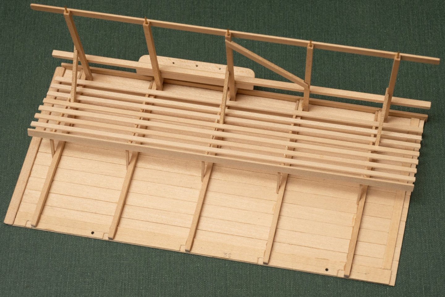
 Olympias has very little in the way of amenities for its crew...However they did fit some stowage racks for gear underneath the canopy. The extent is roughly shown in the midship section drawing (John Coates Plan no.8) but no details or scantlings are given. My interpretation is taken from scaled measurements from images on line and stills from videos (the stick men shown in the sketch are traced from John Coates drawing and are rather taller than my Athenian marines - I guess he was checking clearances for the taller 1980's oarsmen...): And a view of the first canopy section fitted with a stowage rack removed from the model:
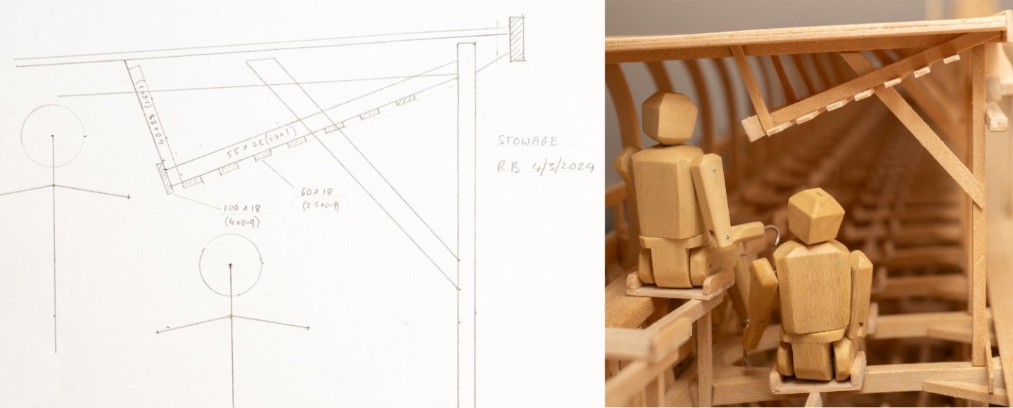
-
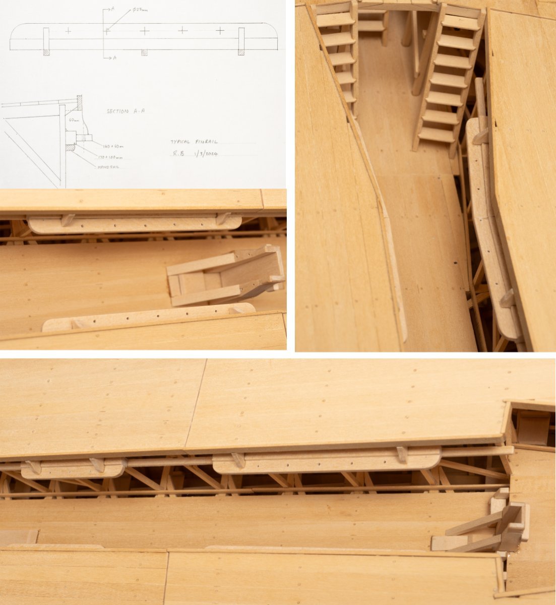
The belaying arrangement for the running rigging seems to have been developed during the build and trials of Olympias as the location of pinrails in photographs and videos of the vessel differ from their positions in the build drawings. Drawing MSR 11 (General Arrangement of Standing and Running Rigging) shows two pairs of pin rails (P&S) at the aft end and forward end of the gangway. their height is given quite low to the deck. Photographs of the copleted ship show 4 pairs of pinrails in total placed on top of the handrail. Ive done my best to scale these from stills taken from online videos (again, I really do (/should have!) need to visit the ship in Athens at some point...). My interpretation below:

-
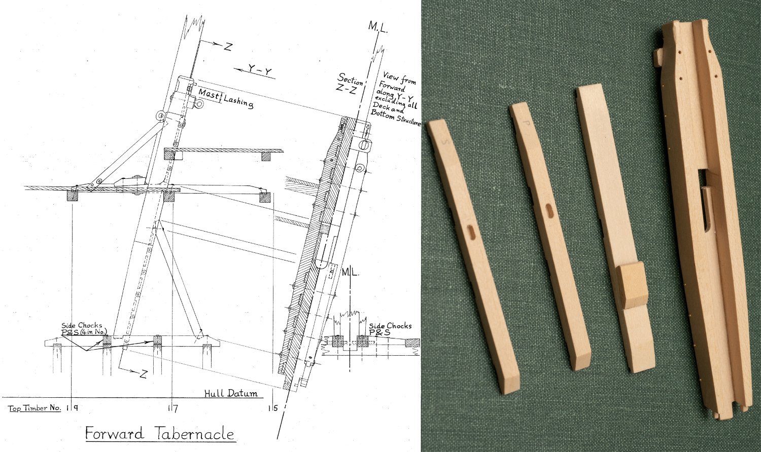
Yes, on Olympias the mast is lashed to at the top part of the tabernacle, where it narrows. Its shown on the extract of Johns drawing I included in my post on Sunday.
-
Ive got one of these to make...I was thinking of making from brass sheet and chemically coloring, but 3D printed and then painted looks much easier, and probably closer in apearance to a casting...
- 536 replies
-
- 3
-

-
- Quadrireme
- radio
- (and 1 more)
-
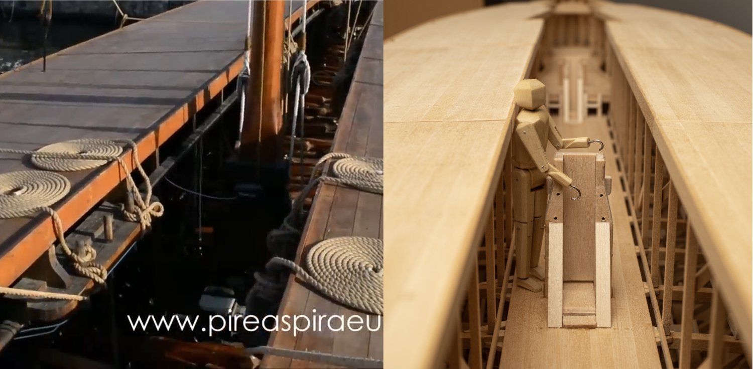
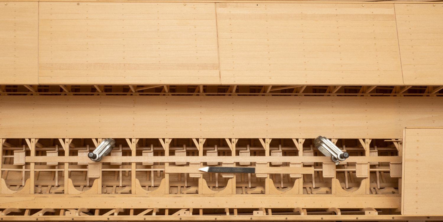
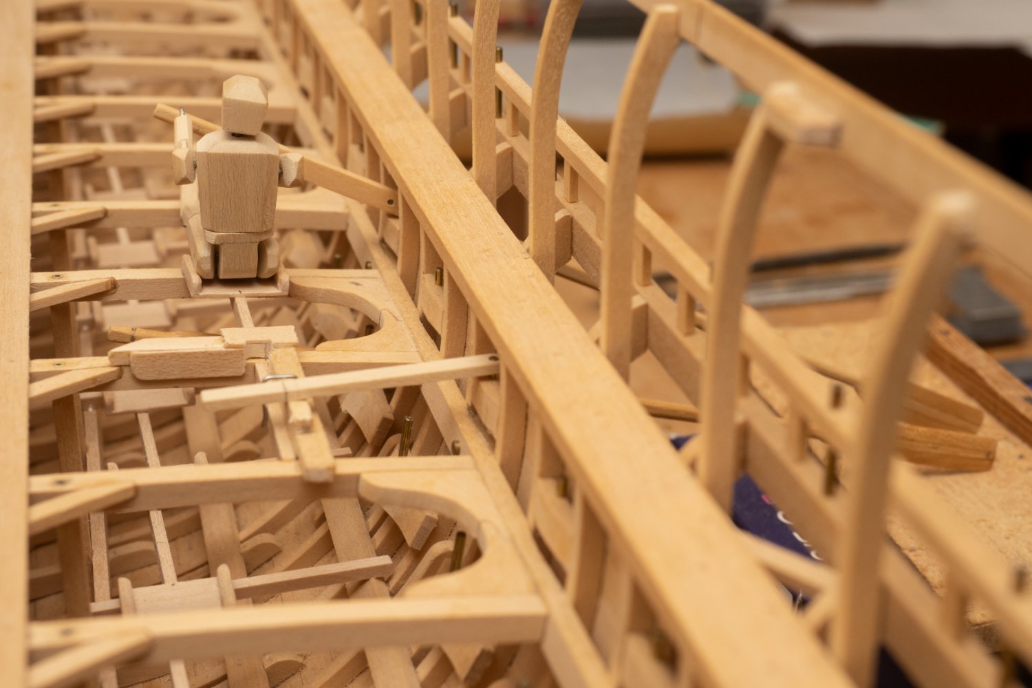
Limited access past the main tabernacle (with the canopy sections back in place) illustrated by one of my trusty marines, alongside an image of the full size Olympias. Interestingly, John Coates drawing shows a canted canopy support (see post above) which might have improved access somewhat. However, it apears from images of the actual ship that this was not done. My model has all canopy support stanchions vertical in line with what I can establish from images of the actual ship and the midship section and forward and aft arrangement drawings (I must get round to visiting myself one day...). Another difference from the drawings is that the handrail has been fitted much higher on the actual ship and serves as a foundation for a number of pinrails. I cant find any drawing of the pinrail arrangement, but I think I can come up with something fairly accurate by scaling from screenshots of the video below. The image above was taken from a still extracted from this video:

-
By the way, and slightly off topic. I was very sad to hear about the death of James Byrnes, the man who built the fantastic table saw that enables me to machine wood to a stunning level of accuracy. He also made a rather lovely rope making machine as well as sanders and thicknessers, which would have been lovely to posess! Link to his site with an obituary. Byrnes Model Machines Home Page
-
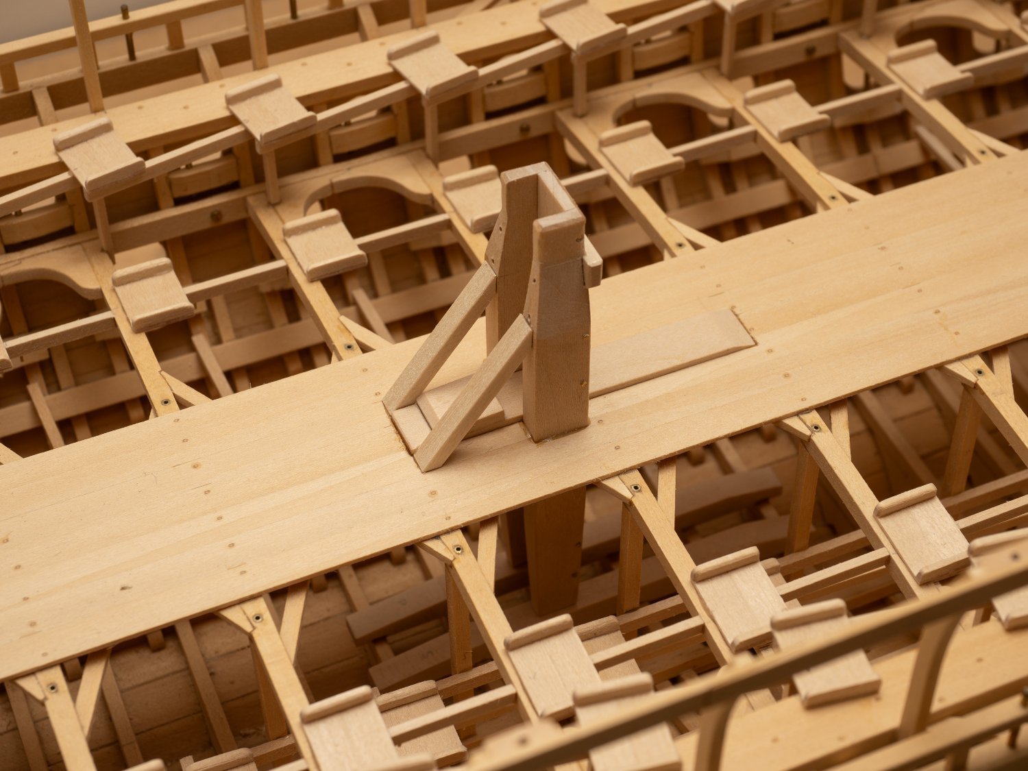
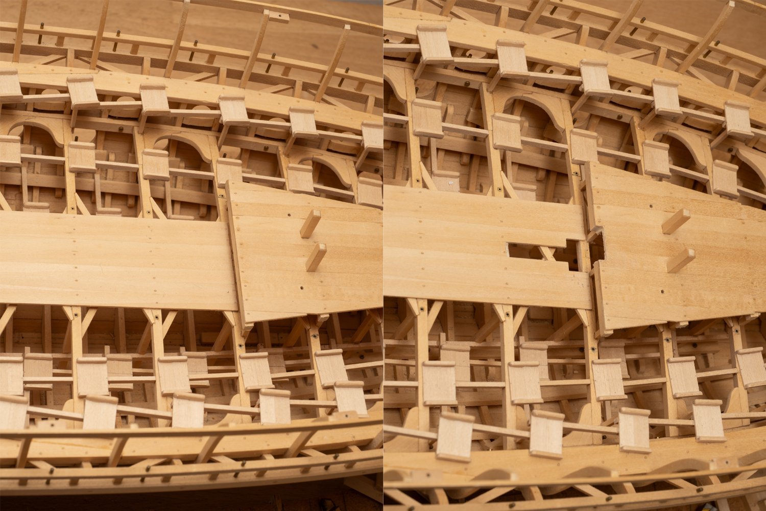
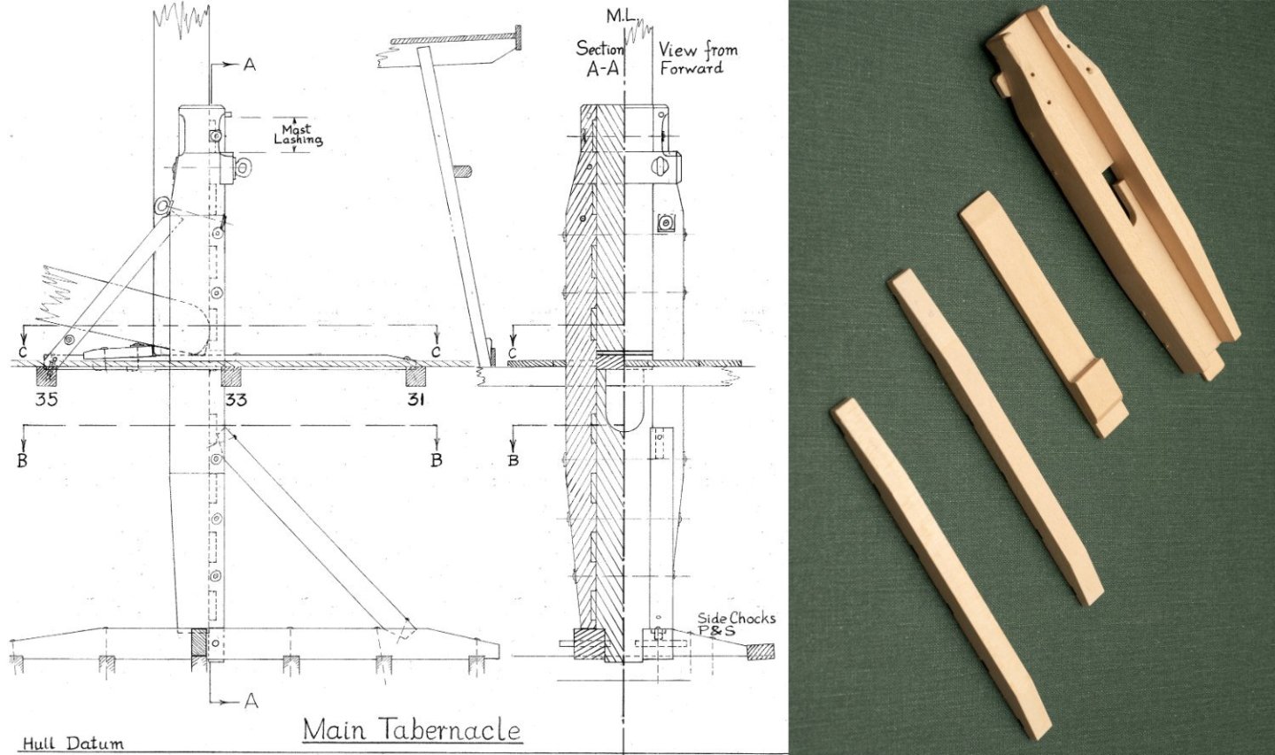
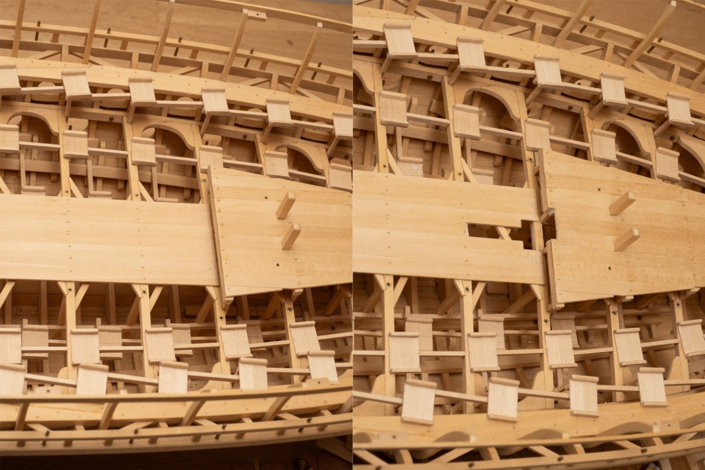
Work proceeding on the main tabernacle. Slighly messy hole for the lower rigging eye on the starboard side of the tabernacle. Despite setting it all up (I thought accurately) on my Unimat, I drilled the hole in the wrong place. The repair involved gluing in a dowel and redrilling....At the moment you can see the remains of the dowel, but that should be covered by the rigging eye when I fit it. I always reassure myself, when I end up doing these bodges/repairs, that this sort of thing occurs in full size ship and boat building all the time. On one memorable project I was involved with a fitter cut a large hole in a main structural composite beam on a high speed vessel. The repair was complex and involved detailed liason with the customer for approval (as it was a lightweight composite structure). Some days after we did the repair the fitter returned and cut the hole again... so we were then in to an even more complex repair of the repair. Another reminder to check drawings before you cut...but we never do do we? Extract of Drawing MSR 12 © Estate of John F. Coates, reproduced with permission.
-
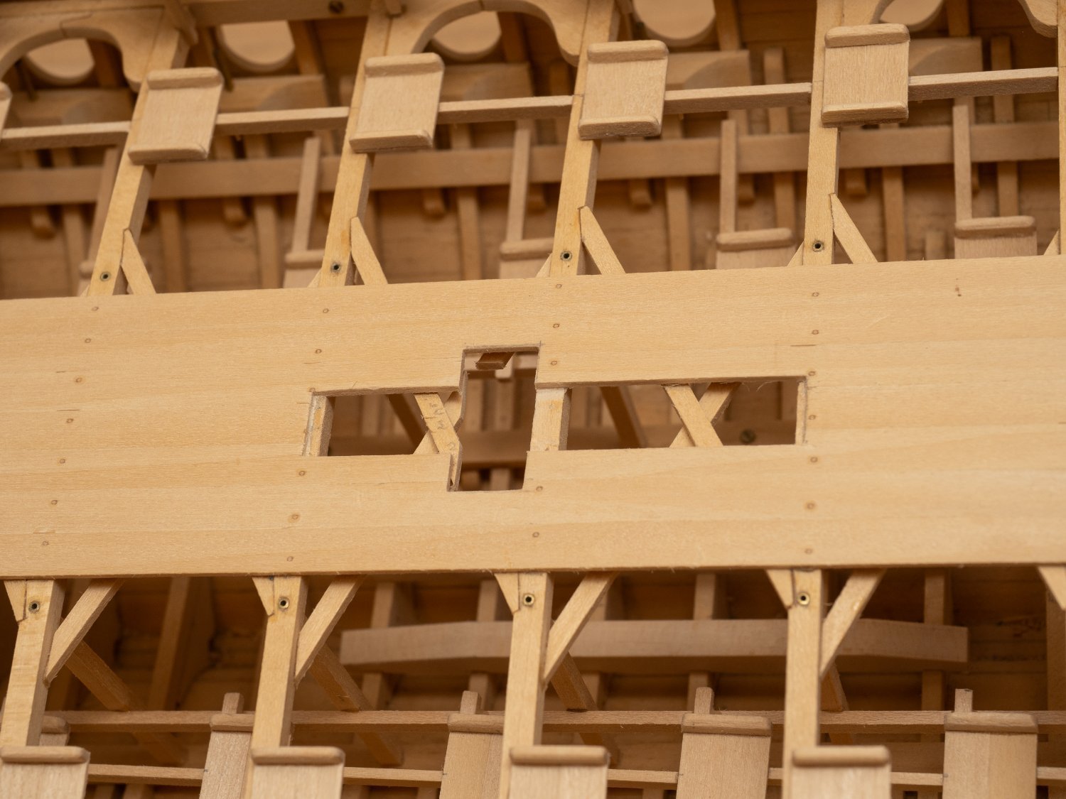
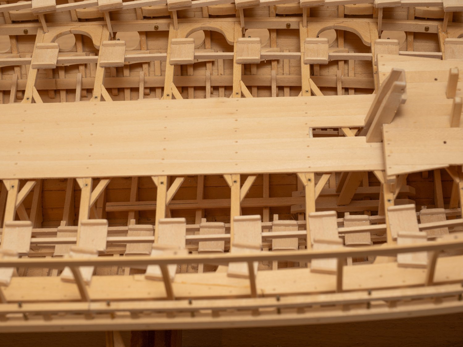
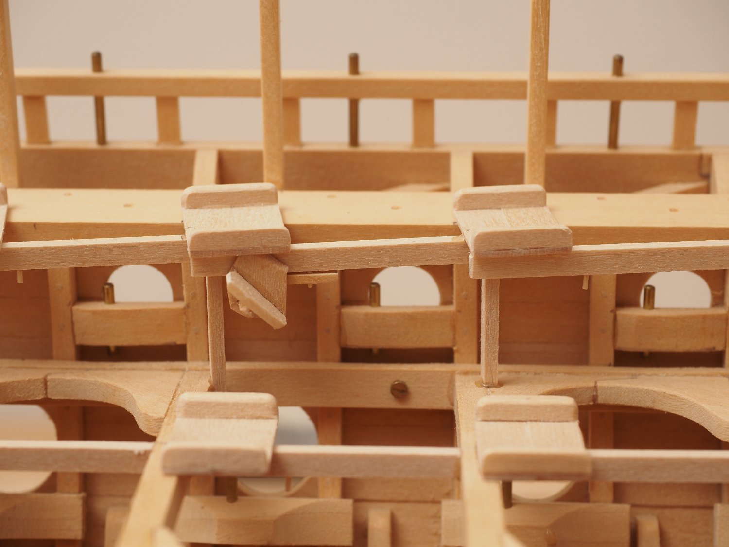
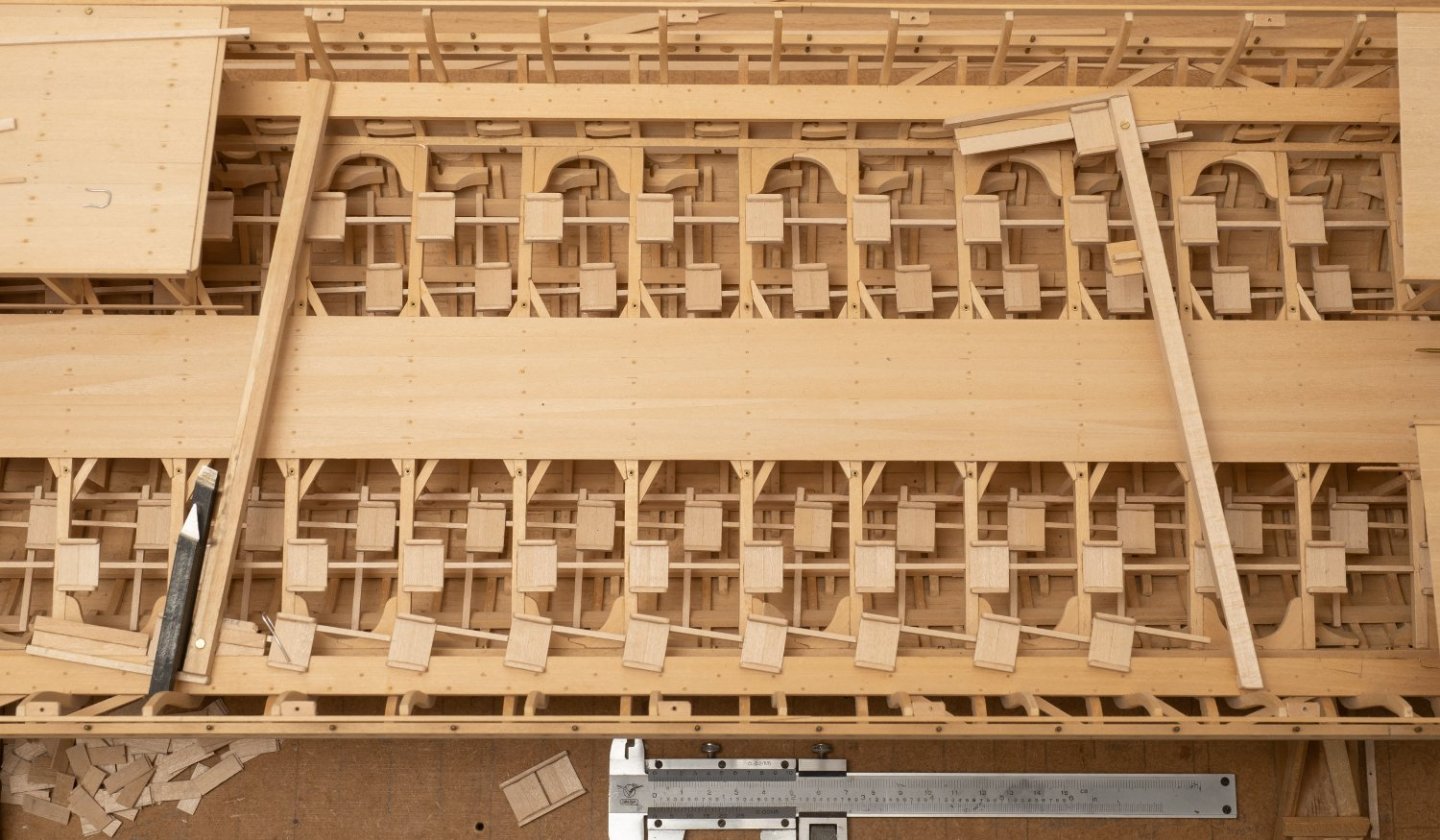
Another example of poor planning... The tabernacle for the main mast is much larger than that for the foremast. So when I make the cutout in the deck for it I also have to cut through the diagonal bracing pieces between teh deck beams. I probably wouldnt have fitted these, had I thought about it. However, they are shown on the midship section drawing (which includes these frames), so I guess John Coates didnt think about it when he did that drawing either! Just shows how important it is to review the complete drawing pack as you make a model (or build a ship) as there are bound to be inconsistencies...

-
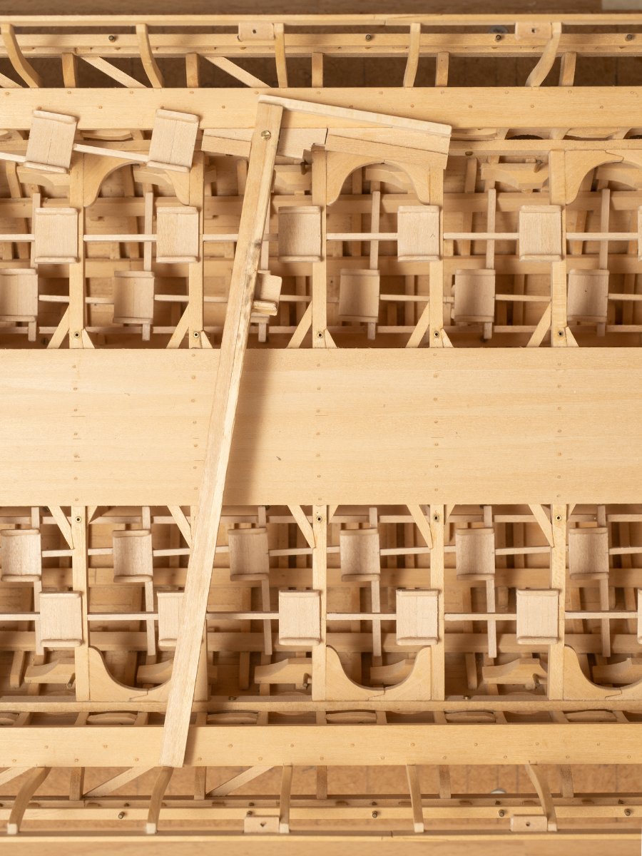
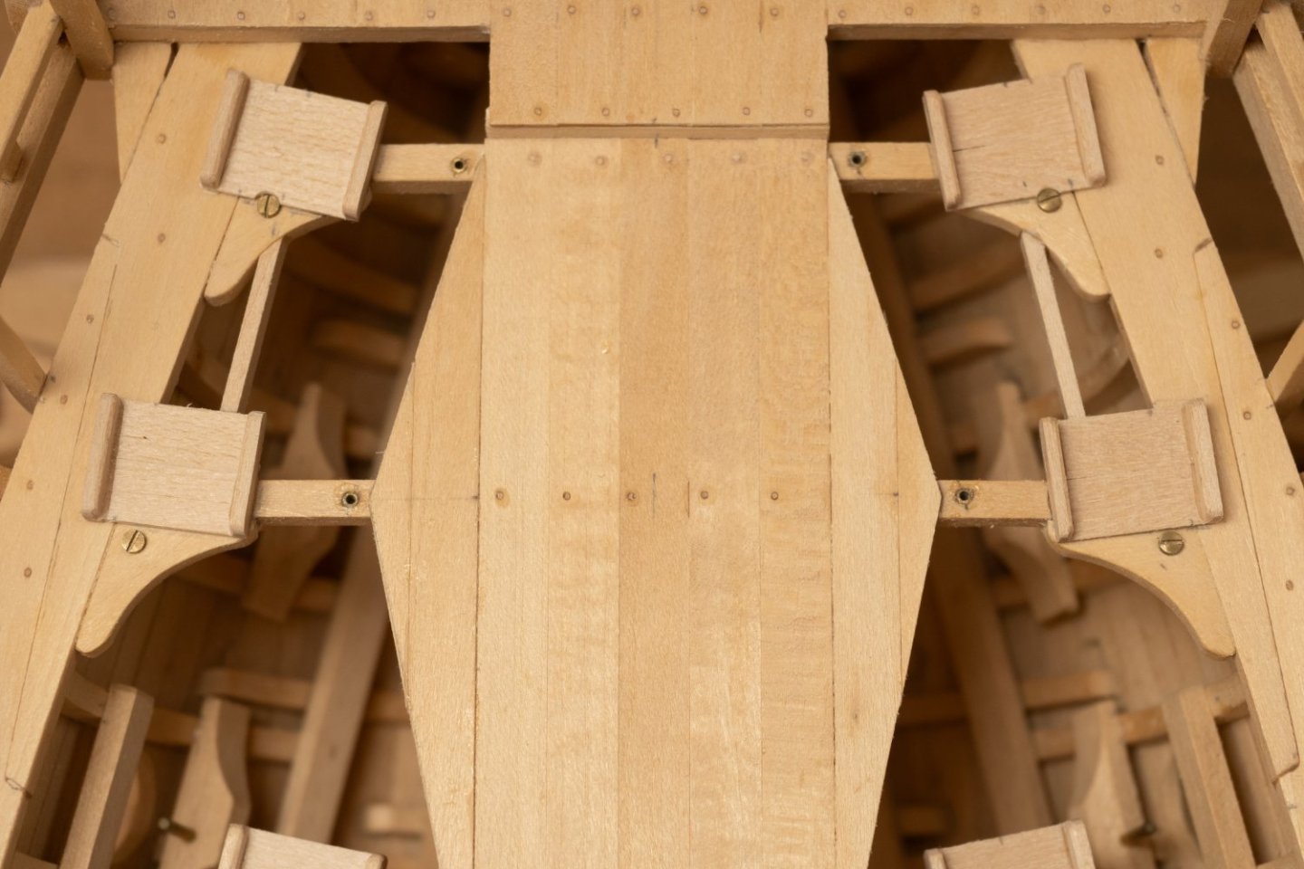
So Im fitting the lower seatings for the tabernacle "remotely" through the deck beams onto the floors. They are both in place with the taberbnacle to ensure proper alignment. The piece of wood lying longitudinally on top of the floor and in between the seatings is intended to help align them fore and aft (the center line drawn on this timber lines up with a centerline mark on one of the floors). The starboard seating has been glued in place in the photo. Hopefully the port one will be easier with the starboard one in place to act as a guide. Not the way I would have chosen to do this if I had planned it all properly. Lowering the starboard seat through the deck beams and into place, after I had applied glue relied on the steadiness of my hands rather more than I usually like to!

-
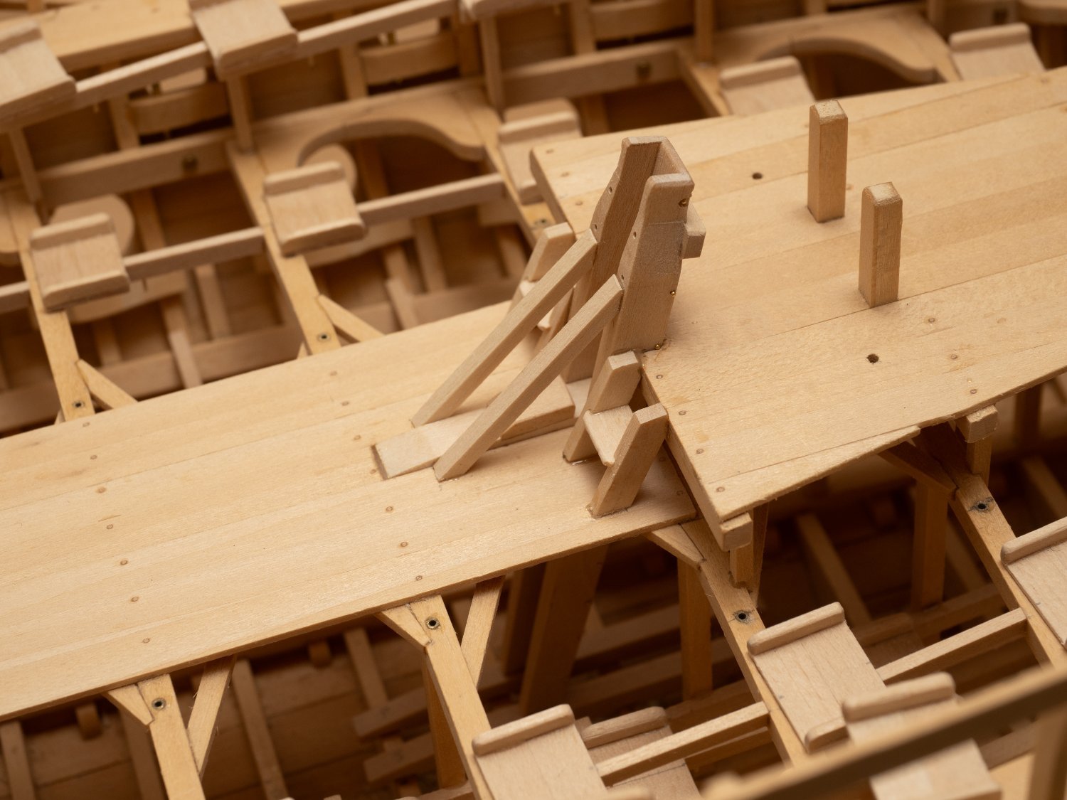
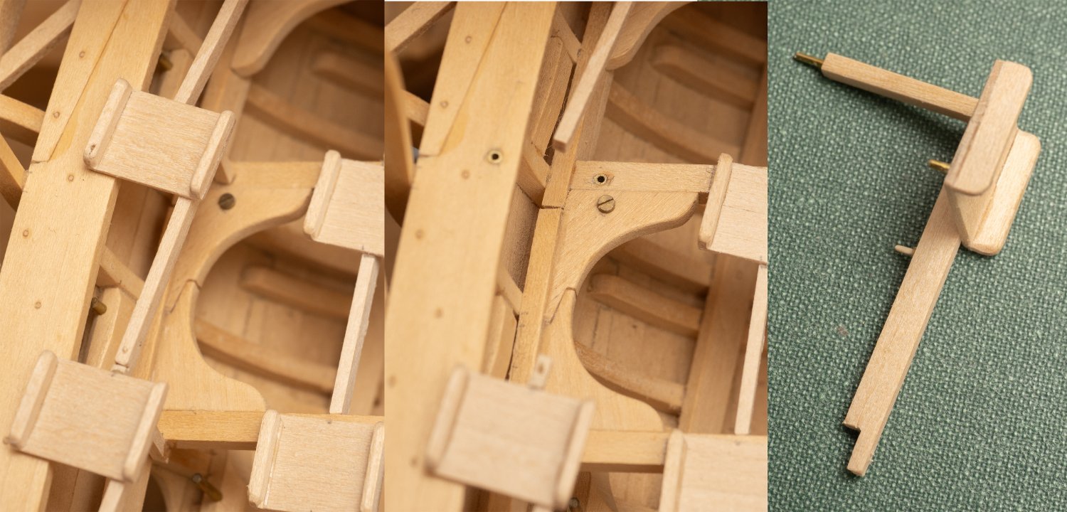
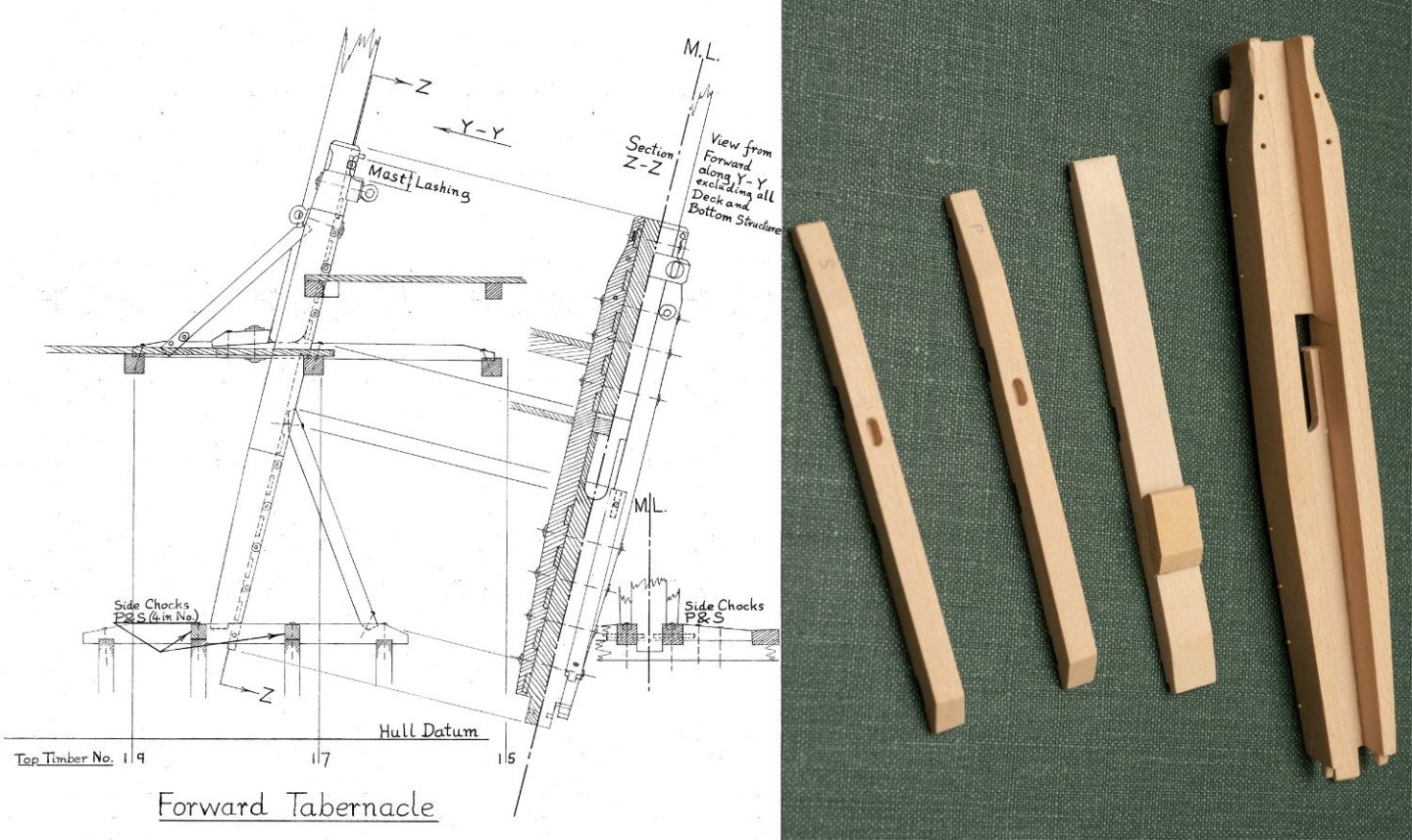
Havent posted for some time... Have been ploughing on with the top level seats, which are now finished. Usually enjoy the therapeutic nature of repetetive tasks, but must admit that 170 seats... Anyway, now putting in tabernacles for masts. Would have been easier to install before planking the gangway, but I am where I am... I took a bit of time to work out how these are constructed from John's drawing (MSR 12 © Estate of John F. Coates, reproduced with permission) and some, not very clear, photographs of Olympias. The main components of the forward tabernacle are shown below: And the hole I have had to cut in the gangway to install it: I was originally thinking I would remove the whole deck assembly (un boltable) to install the lower seating for the tablernacle, but Im now thinking that it will be more accurately alighned if I do it with the deck bolted in place. Just a bit fiddly fitting the timbers through all those beams and seats...
- 261 replies
-
- 12
-
-

-
Simpler at the fore end where the forward most seats on the upper level sit on the removable section. Luckily the bolts that I put in this area cleared them (well almost...). At one point I wasn't planning to fit seats so these bolts were placed without thinking about them...
- 261 replies
-
- 15
-
-
-
Still plodding away with the seats. The series of photos below shows my solution for a removable seat to allow for the removal of the gangway section of the model.

-
Problem with ships having a port and starboard sides is that I need to make two jigs... One benefit is that I can now work on both sides at once, which is speeding up production a bit (from my usual snails pace...)
- 261 replies
-
- 12
-
-
-
First check on the ergonomics with my trusty triad of marines: Still to fit their footrests...

- 261 replies
-
- 13
-
-
-

-
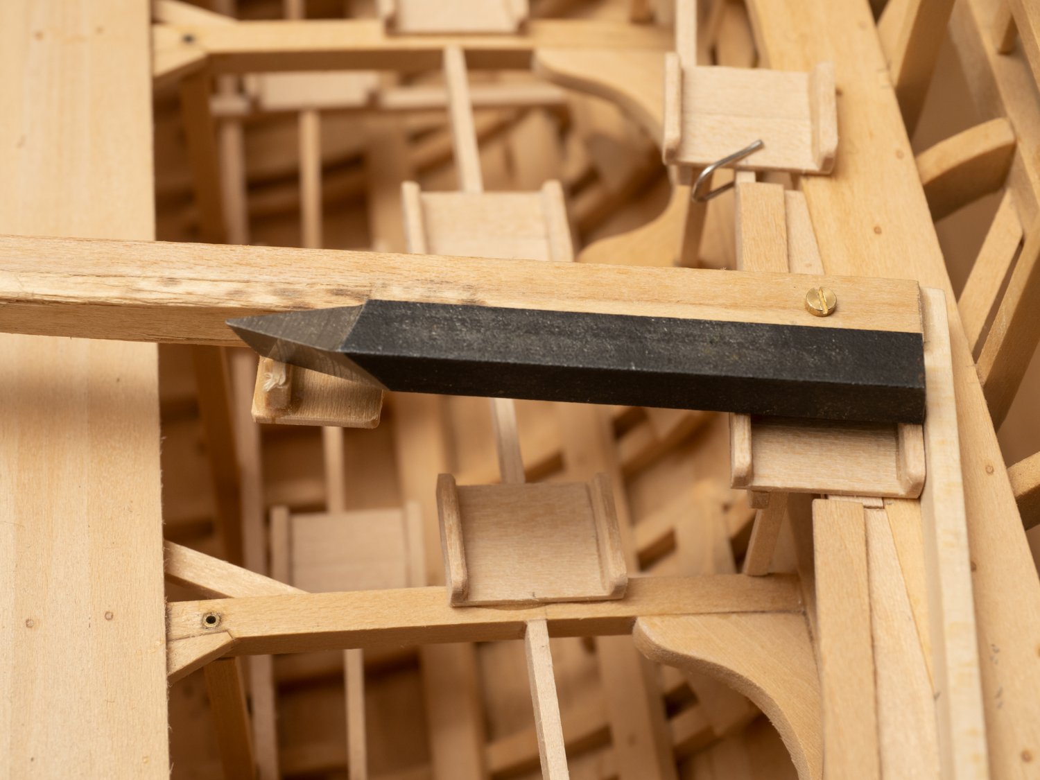
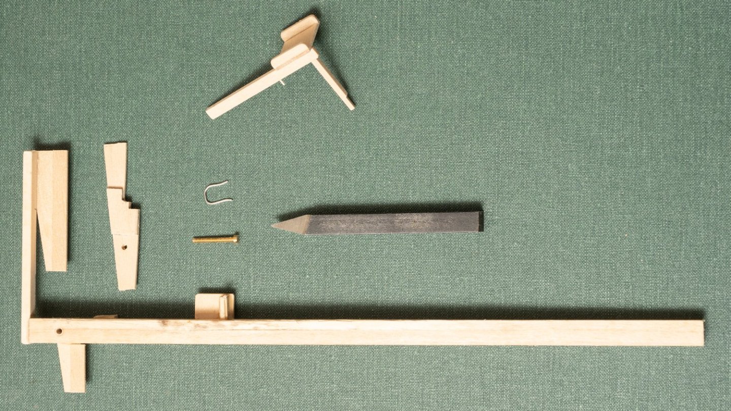
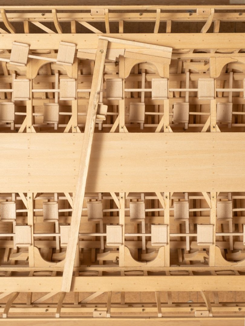
For some reason its taken me a long time to work out how to install and jig the upper seats... The jig ive ended up with at this stage is shown below together with a seat assembly (seat+ foot stretcher + support pillar). The jig consists of two parts. The main part is intended to hold the seat level athwartships and at the 9 degrees rake to the centerline with a removable section that can be unbolted so that the jig can be removed after fixing the seat in place. Here is the jig in place in the model: And, finally with the seat assembly in place: The seat is assembly is fixed to the seat forward of it by its foot stretcher (held in place by the steel clip while the glue dries) and to the beam underneath by its support pillar. The intention is that all the seats form part of the removable part of the model and so this seat assembly can not be glued to the sheer capping... The lathe cutting tool is functioning as a weight to hold the seat down in the jig while the glue dries...

-
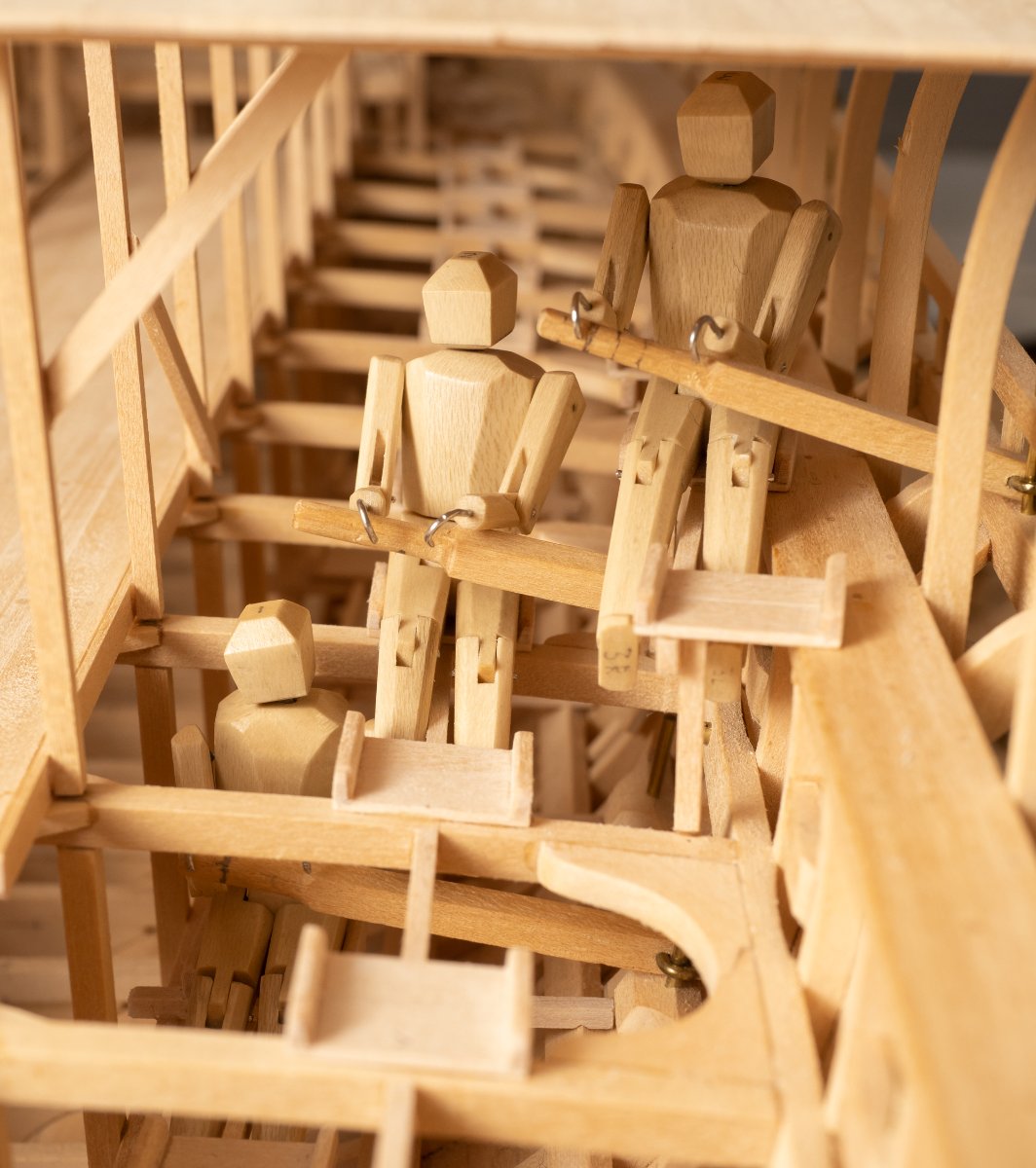
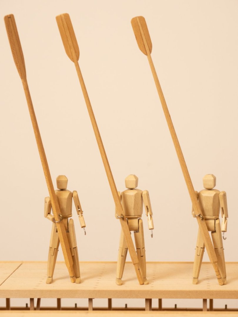
My triad of oarsmen completed. From right to left: Thalmian, Zygian and Thranite oarsmen holding their appropriate oars. The oars shown are based on the original oars for Olympias which were used for most of the sea trials. The blades are designed with a different shape to account for the differing vertical angle of immersion for the three different levels. A lighter version of the oar was later trialed (where all three levels used the same design).
- 261 replies
-
- 13
-
-
-
The middle tier of oar seats are much more straightforward to install than the lower tier as they are not raked relative to the vessels centerline. This means I can align them easily with a straight edge. Here are 3 going in in one gluing operation:

- 261 replies
-
- 11
-
-
-
Yes, I am finding that 1:24 is about as small a scale as I can manage. The main reason for the full scale reconstruction was to demonstrate that it was possible to arrange 170 oarsmen, each with their own oar, in a ship 37m long... So I wanted to be able to show that this could work on the model... The clearances between the oar blades, and hence the geometric tolerances for building many critical areas of the ship, are necessarily very tight to achieve this even at full scale let alone on a model...
-
Starting the installation of the second tier (Zygian) of oarsmen seats. Again, my Manikin is helping to confirm that the seat is in the right place for the downward angle and sweep of the oar and that there is no interference with the lower (Thalmian) oarsmen. The oar blades ae resting on a block of wood placed to give the right downward angle for complete immersion of the blade in the middle of the power stroke (at the design displacement). One the inboard distance of the seat is established I constructed the jig for installing the oarsmen stretchers at the same distance from the tholes which can be seen in the next bay forward of the manikins position. Part of this jig holds the new stretcher in place, perpendicular to the deck beams and the other part is a simple "ruler" that fits over the thole pin marked for the correct distance inboard. I will need to remark this for the shorter oars at the ends of the vessel...

- 261 replies
-
- 13
-
-
-
Yes that is still the plan. However, at the moment I am concentrating on completing the model with as little concession to that as possible. I want the mechanism to be fully removable so that the model can stand with or without. That is on of the main reasons I have made it fully capable of dismantling.
-
Disassembled the model today for the first time in a very long time, to check that I haven't done anything to stop me being able to get at the bolts and that the main hull outfit assembly (which includes deck beams, support pillars, inner hull longitudinals, gangway, and now thalmian seating...) is still removable. It takes me just over half an hour to assemble (there are 82 bolts to secure in total...) and I was quite pleased with how easily the main hull outfit assemble fitted into place with no flexing at all and all the bolts perfectly lined up with their holes. I'll have to do it again to fit the mast steps (I know, I could have done that before I put the deck in...) and I'm hoping it will make it easier to get at everything when I finally come to coating the wood with something.

- 261 replies
-
- 19
-
-