KrisWood
-
Posts
314 -
Joined
-
Last visited
Content Type
Profiles
Forums
Gallery
Events
Everything posted by KrisWood
-
Redoing Oseberg
KrisWood replied to KrisWood's topic in CAD and 3D Modelling/Drafting Plans with Software
I managed to get Rhino back up and running, so I'm going with that rather than trying to learn a new software package for now. That said, I've now got two goals: 1. Get my current Rhino files into a format suitable for CNC mill and/or 2. Get my current Rhino files into a format suitable for cutting out in card at a smaller scale While the former is certainly more exciting, as I'd get to build in wood, the latter is more feasible as I do not own a CNC milling machine and cannot afford one. I'd need a co-conspirator to help with the milling of the parts for the foreseeable future. My next question is, would anyone like to participate in a group project to (and / or give advice on how to) develop the plans into a mill-able / cut-able format? PS. I've already done most of the work, just need help figuring out where to go from here...
-
Good news, I got the rhino trial working on my new computer. I've got 90 days to come up with useable plans.
-
You may have just corrupted me completely. 😆 Now to reduce my scale and figure out what software to use...
-
Redoing Oseberg
KrisWood replied to KrisWood's topic in CAD and 3D Modelling/Drafting Plans with Software
I’d like to work with wood. I just couldn't cut anything accurately to save my life. I'll save up for a mill and focus on design and assembling the parts. First though is figuring out which software to use. I tried Delftship and got as far as setting up one reference image. So far its interface is completely alien to me but I'll keep at it for a bit and see what I can come up with. -
Redoing Oseberg
KrisWood replied to KrisWood's topic in CAD and 3D Modelling/Drafting Plans with Software
The problems with my build were not with Rhino itself, except that it isn't free and I don't have access to it anymore. My problems were mainly with lacking the skill and depth perception to make the parts by hand. Once I'm up and running again, the goal will be to make files suitable for CNC mill or laser cutting so that once I can afford one, or find somewhere that can make the parts, I can use them to get all the parts cut out. -
Hi all! Some of you may already be familiar with my much troubled scratch build of the Oseberg Ship (working from these plans). With my wood tools indefinitely in storage and without a license for Rhino at the moment, I'm on the lookout for free alternatives. The end goal will be to have the parts milled from the 3D files at some point in the future. This begets three questions: 1. What is the best free hull / part modeling software available. 2. Can this software model clinker hulls? 3. Can this software import Rhino files? Currently at the top of my shortlist is Delftship, which can certainly model hulls, though I don't know about parts or clinker planking. I'm having a hell of a time just getting acclimatized to the interface at the moment. Next up I'll try Fusion 360, which looks more familiar given I started in 3dsmax and Autocad many years ago, but still foreign to my more recent Rhino experience. I'd love any suggestions.
-
@mtaylor all my tools are in storage, along with my supply of wood for this project. That's why I was thinking I'd switch to card. Much cheaper and easier to work with an X-Acto knife and paper and I can do it in a tiny apartment while waiting for my house to be repaired.
-
Hi Petr! I'm revising my Oseberg project to mirror your Gokstad project. Are you still around? I could use some pointers. What software did you use to draw/print your parts? Sorry, it's been a while, I forgot you're using Rhino Could you please describe your technique for building up layers to scale thickness? Thanks! Kris
-
Hi all, it's been a while. Within days of my last message here, my house was flooded (aka destroyed) when an upstairs toilet malfunctioned overnight and continually filled the downstairs ceiling with water. My possessions have been in storage ever since and my project has been on hold. Since then, I've also lost access to Rhino 3D so I can no longer use the files I had been working with, so I can't even work on the digital version. Alas. Also, even if I could make use of my files, since all my money is going into the house repairs, I can no longer afford the CNC mill I was going to get to continue the project in wood, so meh, I'm all out of luck. Meanwhile I dreamed last night about picking up the project again and it was fun so I'm thinking about, how can I do this in a way that makes sense with the tools I have available.... A computer A MASSIVE amount of reference materials and research I can probably afford to work in card and have plenty of knowhow to make that work if I can learn just a few things... What I need: Free software that can draw/print scale plans on card Help figuring out how to build up layers of card to scale thickness Now to get started!
-
While I have the utmost respect for those who can actually make use of hand tools, I'm afraid I have never managed to gain any skill with them. My lack of depth perception is the main impediment. I have the worst aim with cutting tools, and have a very hard time telling the difference between two similar sides of an object or whether one plank is larger than another or slightly off in any given dimension unless the planks from each side are exactly lined up on top each other. I am meanwhile highly skilled with computers, so I'd rather let the computer handle the accuracy and only assemble the parts by hand.
-
Which CNC Machine to get?
KrisWood replied to KrisWood's topic in Modeling tools and Workshop Equipment
I hadn't considered it but really I'm not that handy. I'm a software guy, not hardware. The assembly of the premade CNC will be challenging enough as it is. 🙂 -
Which CNC Machine to get?
KrisWood replied to KrisWood's topic in Modeling tools and Workshop Equipment
...or I could just do my model at a smaller scale... Edit: ok I did some more research and the 4030 without the extension will be plenty for now. First, my rounding was wrong before. I was covering from metric to inches and back again and made rounding errors each time. The longest part of the model is the fore segment of the keel which is exactly 15m at 1:1 or 600mm at my current 1:25 scale. Even with the extension this would mean using the entire length of the workspace or going diagonal. However, I looked up how to carve pieces longer than the workspace and it turns out to be relatively simple. It's just a matter of breaking the drawing into multiple sections, and including locator holes for the mounting screws with each cut. After the first cut, slide the workpiece to the next set of holes and run the next drawing which includes the locator holes for the following cut. Each overlaps a little. I think this will work! -
Which CNC Machine to get?
KrisWood replied to KrisWood's topic in Modeling tools and Workshop Equipment
I’ve looked up the Sainsmart 4030 with 6060 extension, and the 6060 table which is sold separately. It's a bit out of my price range at the moment, coming to a total of $1477. I wonder if I could get by with just the 4030 for now and do half of my keel at a time. I think I'd just have to be very careful about aligning the work piece. Hmm..... -
Which CNC Machine to get?
KrisWood replied to KrisWood's topic in Modeling tools and Workshop Equipment
24 inches is just a bit over 600mm, but fits well within the diagonal of 600mm square, which comes to just under 850mm. Now I know my dimensions, I just have to find the best quality for the price. -
Which CNC Machine to get?
KrisWood replied to KrisWood's topic in Modeling tools and Workshop Equipment
To follow up on that last post, the largest part of my model at 1:25 is the fore keel segment at approximately 23 inches long. -
Which CNC Machine to get?
KrisWood replied to KrisWood's topic in Modeling tools and Workshop Equipment
Thank you everyone for the replies. I had looked at some of these before but am having a really hard time telling the difference between the real ones and the knock-offs online. I’m looking to stay in the $400 to $1100 range so that limits my options a bit. So far the largest one even close to that price range seems to be the Bob’s CNC machines. Has anyone tried these before or have any idea how they compare to the competition? -
Hi all! I'm looking into CNC machines and am having a hard time figuring out what to get. Preferably something that can handle up to 24 inch pieces, or I'm going to have to shrink the scale of my 1:25 Oseberg. I don't think I need more than a 3 axis machine because all parts can be milled in two dimensions plus depth. What brands are good? Thanks! Kris
-
Looking great! She reminds me a lot of La Diligente.
-
Hi @mtaylor, No, I don't have a scroll saw. I do have a similarly table mounted jigsaw that does a similar job but it's not as accurate.
-
Oh! I have an idea! I could start by doing a cross section model. That would give me all the requisite skills and would allow me to focus on one part of the ship instead of the whole thing!
-
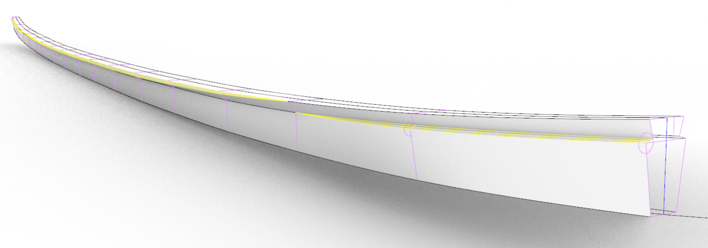
I've been pondering how to save my project so that I can actually build it in wood. I'm coming up rather stumped. I have three options... 1. Save up and buy a CNC mill to cut out the parts, then learn how to use it 2. Find someone who lives near me so has such a machine and ask them to cut the parts out for me 3. Learn how to use hand tools correctly, and do it the old fashioned way... Well, one of those is certainly the least expensive, especially considering I've already bought tons of hand tools for this project. It all comes down to the keel, really. If I can learn to carve the keel correctly, I can learn to do the rest. So my question for all of you is, how would you carve this keel in one piece? What tools would you use? How would you keep all the angles and curves accurate? Most important is that the rabbet must be the exact angle as in the plans, and must flow smoothly into the T shape of the middle of the keel at the correct angle or the garboard strake will be out of alignment which will throw the whole hull out of whack.
-
Cool! What will you build first? I'd love to follow your build log if you have one.
-
Hi Christian, This is very possible. I think it's more that the original drawing was done in Rhino, then rendered to PDF as a raster image, then the pixels have been brought back into Rhino. Thus it's very difficult to tell exactly which pixel goes at exactly which point. You can get a 90 day trial of Rhino for free from their website.
-
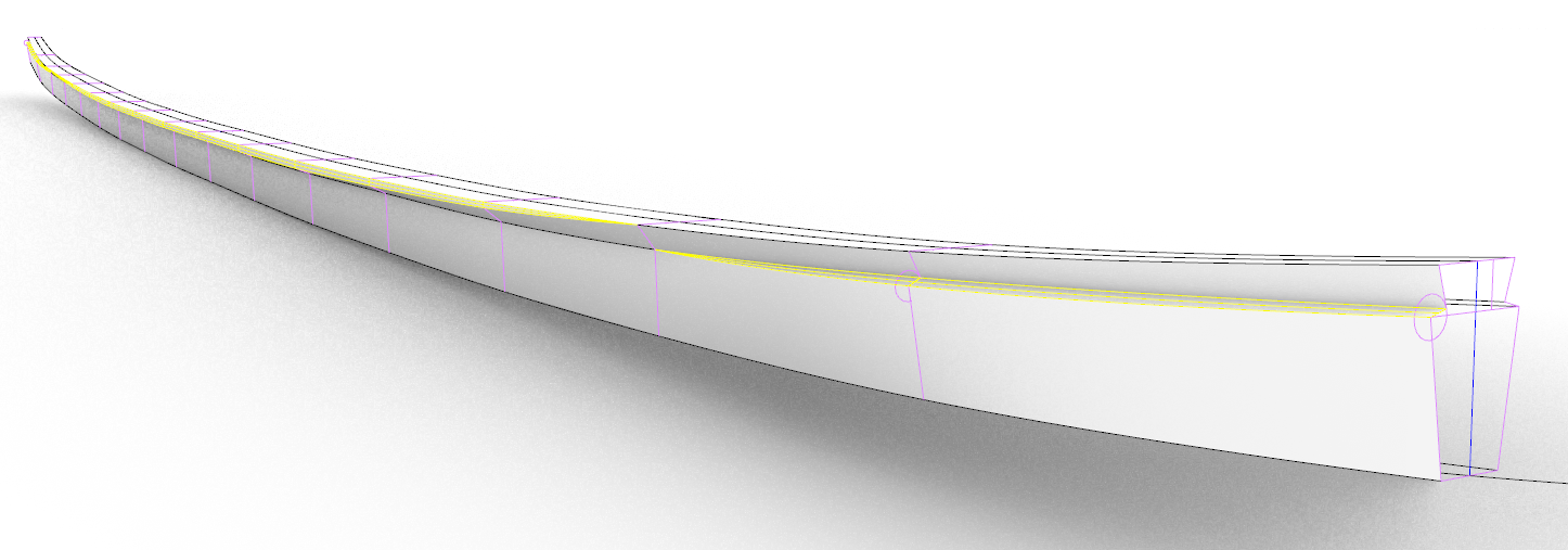
I hate to say it, but I think I must admit defeat on the Rhino front. I simply cannot get all three views to align with each other no matter what I do. If I draw a line in one view, it doesn't match the others. To test this out I went back and re-drew just the garboard strake by extending the contact surface of the keel / rabbets. to the first line in each view. No two views lined up with each other. Furthermore, after reading more of Ms Bischoff's report, I realize that there are only three dimensions that matter in the entire ship now that I have scaled plans for the planks. Those dimensions are the width of the keel, the width of the contact surface with the garboard strake, and the thickness of the planks. All other dimensions can be derived from these because the hull is built keel, then strakes, then frames. Unfortunately I lack the woodworking skills to fashion the keel, so even through I have drawn it accurately in Rhino, I cannot make it in wood until I can save up for a CNC mill. One day...