HOLIDAY DONATION DRIVE - SUPPORT MSW - DO YOUR PART TO KEEP THIS GREAT FORUM GOING! (Only 20 donations so far - C'mon guys!)
×

KrisWood
-
Posts
314 -
Joined
-
Last visited
Content Type
Profiles
Forums
Gallery
Events
Everything posted by KrisWood
-
 I just did the math, I was wrong. The land on the original ship was 40mm, so at 1:25 that's 1.6mm.
 -
On my model, the land is about 1mm also, so I think that should work. Mine is a scale approximation of the lines from Saga Oseberg so I think it's pretty close.
-
Hi @kentyler, It's been a long time since we last talked! I'm glad to see you're still working miracles in paper, and will follow this thread with great interest. Did you by chance keep photos of your gunboat Philadelphia? I found this thread by searching for that one while trying to help a friend with a paper ship modeling project. Anyway, I hope you are well, and keep up the excellent work!
-
Hi @AnobiumPunctatum, Yes, I’m still planning on building up the keel out of layers. My woodworking skills are insufficient to craft angled scarfs and the T shaped wings of the keel by hand, so I’ll build them up one layer at a time and sand them down. I haven't honestly given much thought to the decorations. They are far beyond my skill level and I'm not sure how I would go about them. I'll give it my best effort, but may very well leave them out for this project. It's more important to me that this boat floats than that it be an exact replica.
-
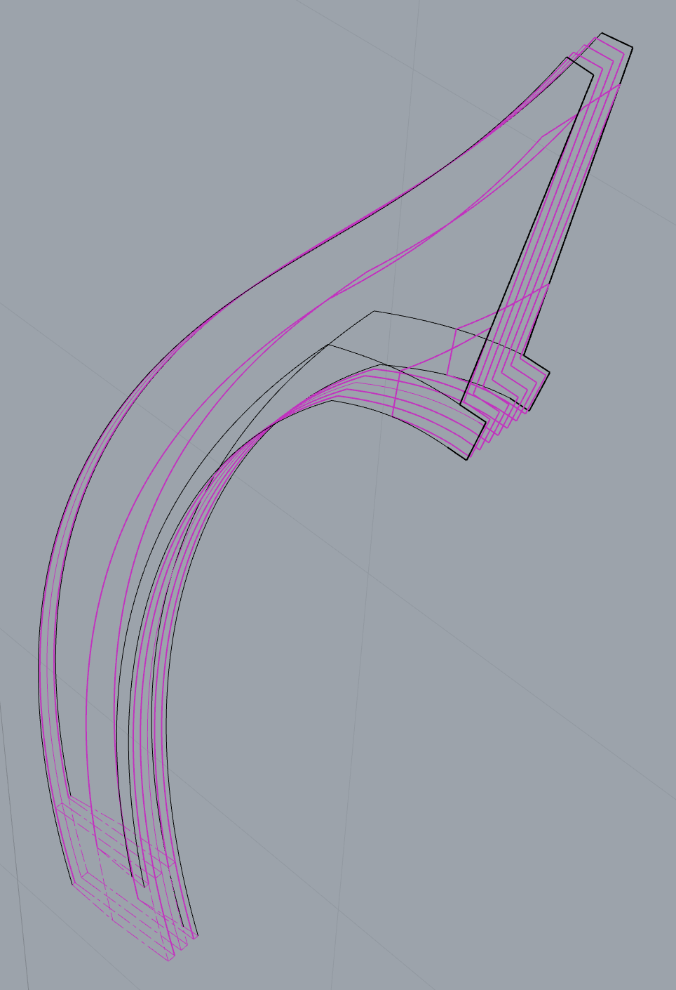
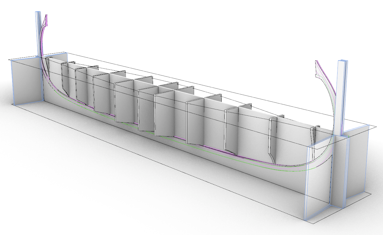
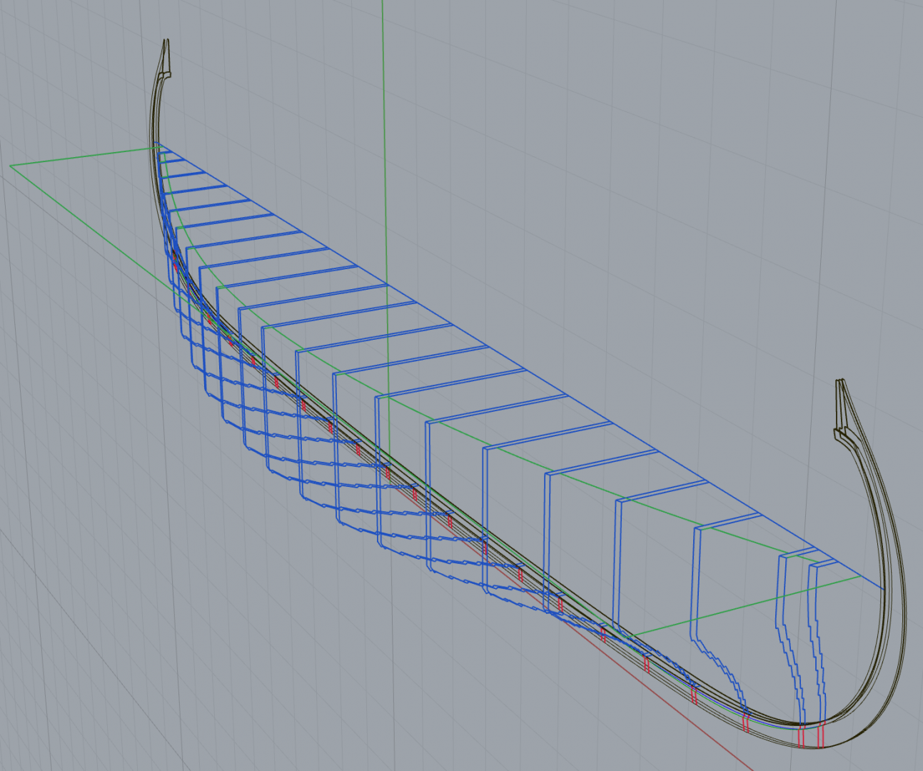
It's the end of the road for CAD work. I'll be losing access to Rhino soon, so here's the final CAD screenshot. Everything else will be photos of wood from here on out. This is the completed jig design. I'm not sure if all of it is necessary, and may not end up building it this way, but it would support both the keel and the cutout. I've also made the cutout opening wider in this version than my last screenshot. The jig height is set up so that the cutout is exactly halfway up the keel and it can be flipped over with zero change in geometry. The bulkheads will only be used in the upside down position while placing the first five strakes. After that I think the hull should be sturdy enough to flip it over and remove the bulkheads and cutout. I've never done this before so please tell me, does this sound like a sane way to build a model? Next step will be printing out all my parts and backing the files up to the cloud for when I'm able to get Rhino again some day.
-
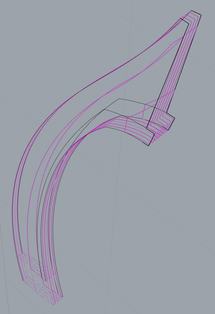
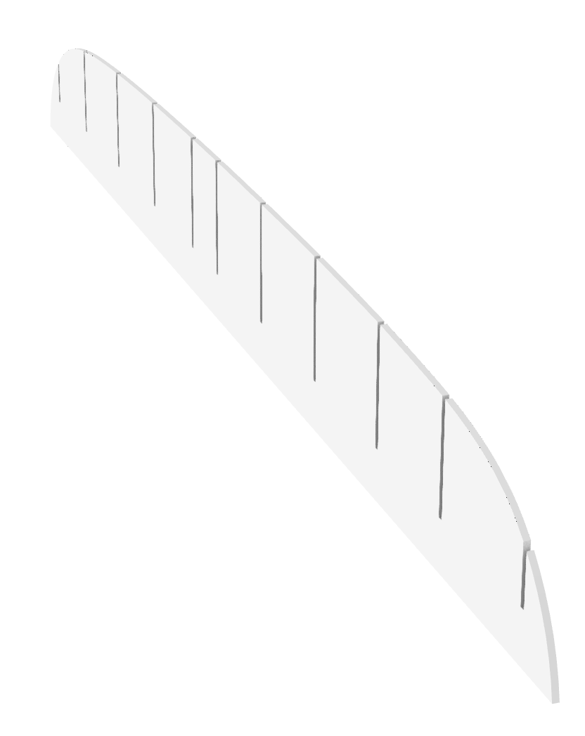
I've completed redrawing the layers of the keel and stems with the new dimensions. Now to arrange all the parts for printing on card and cutting out.
-
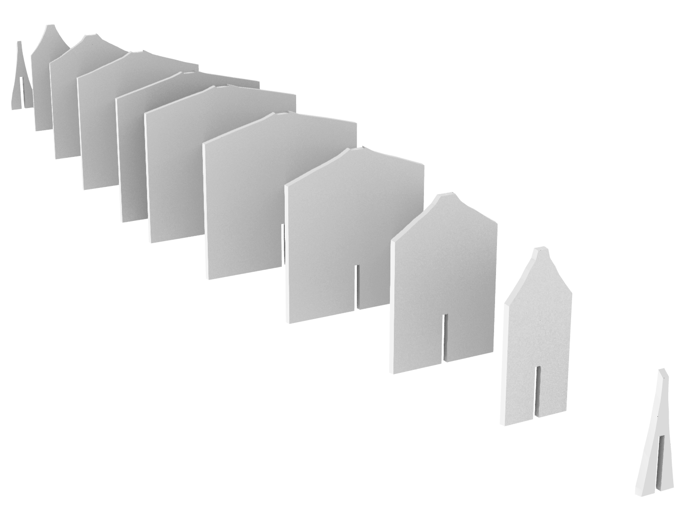
Almost done designing the new jig... Bulkheads: False Keel: Assembled with keel in place: First five strakes: After the first five strakes are installed I will be removing the bulkheads/false keel assembly and turning it upright. Next steps will be: 1. Design the uprights that hold the keel in place 2. Design the horizontal cutout with notches for the bulkheads 3. Design the strips of wood to go on the baseboard to hold the keel in place when upright 4. Slice the keel into cross sections and scarfs so I can build it up out of layers 5. Print templates and start cutting things out of wood! I'm so close and so excited!!!

- 443 replies
-
- 10
-

-
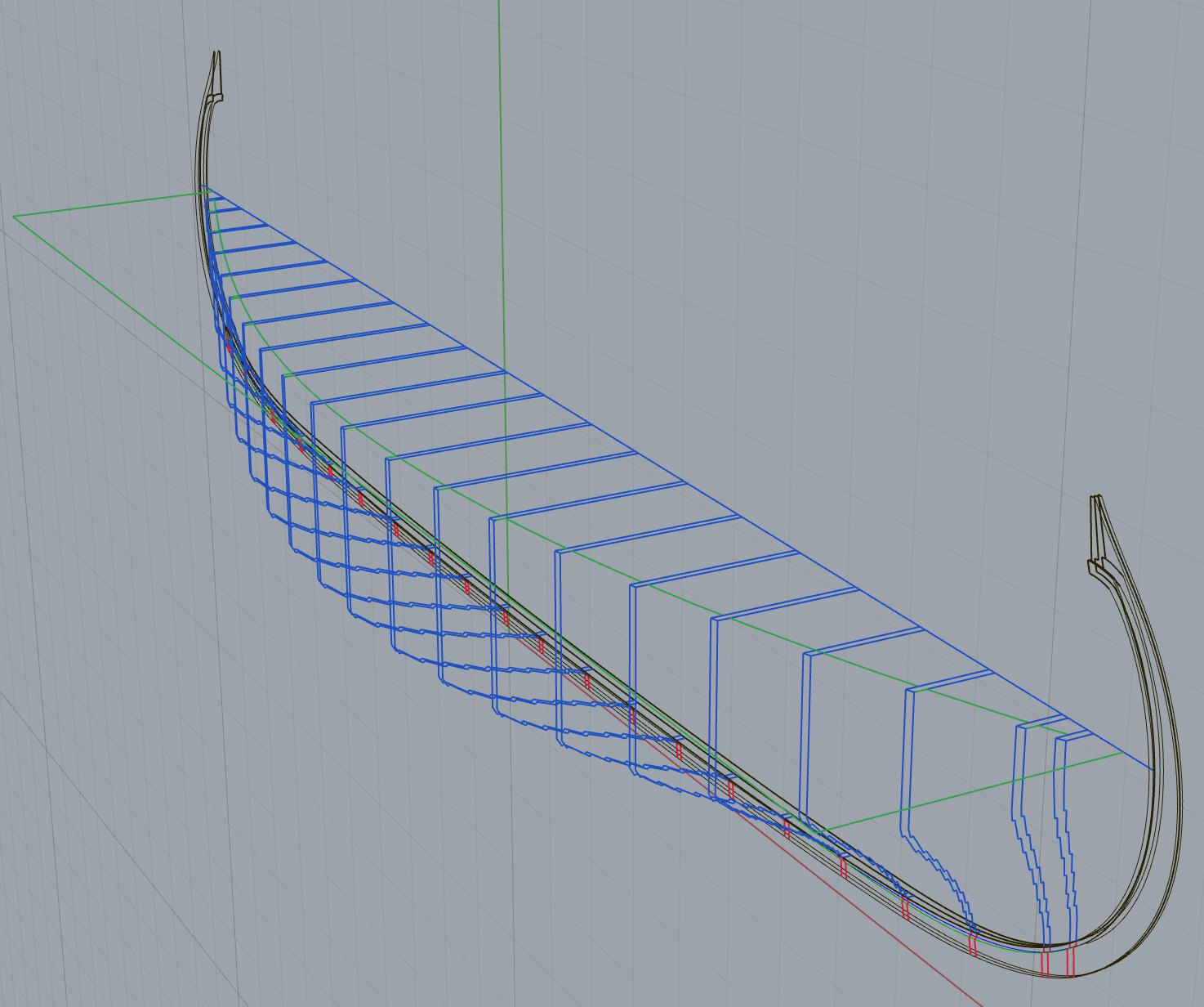
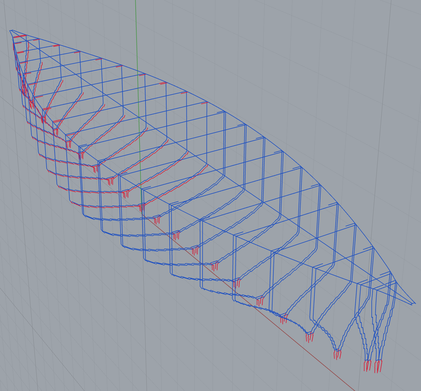
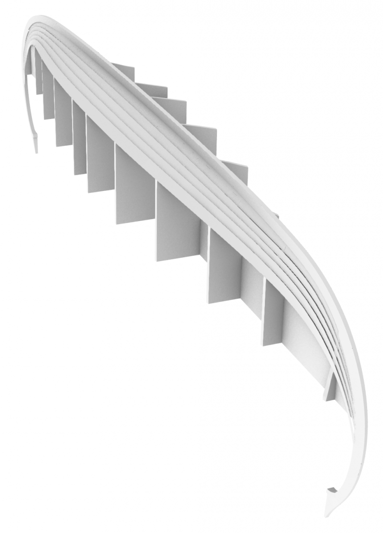
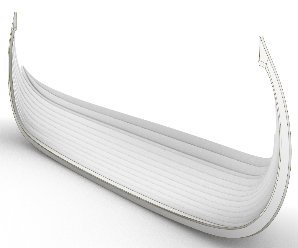
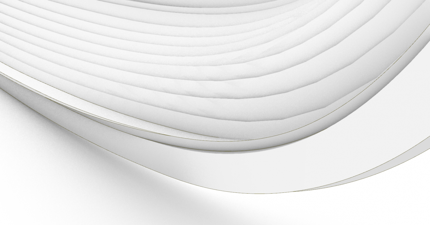
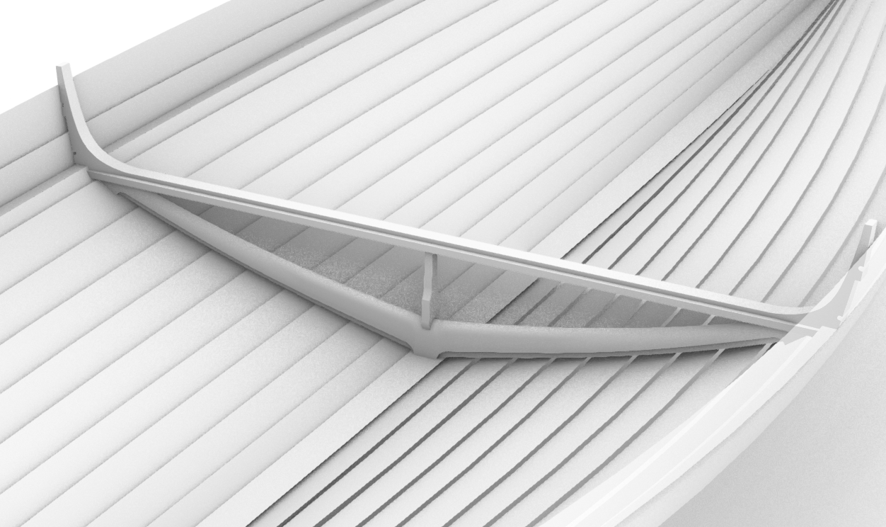
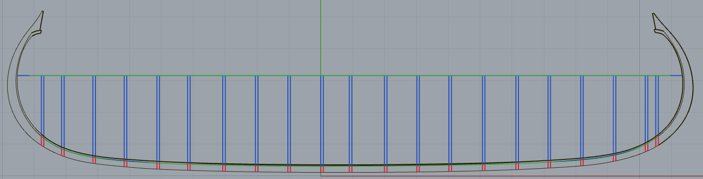
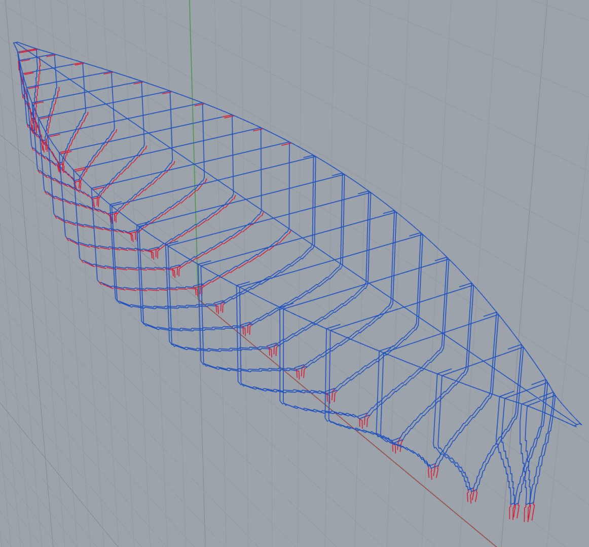
New keel complete and ready for cutting into layers! I finally managed to get a perfect transition from T to rabbets: The trick was to toss out the cross sections from the Saga Oseberg book entirely and cut them from the keel using the inner face of the garboard strake to define the shape. It's still nearly identical to the version in the book, but much easier to model. Here's the completed keel altogether: There are no rabbets cut on the stems because they had none on them in building Saga Oseberg until each strake was attached. They connected the stems without rabbets, and then cut the rabbets while fitting each plank to the stem and stern. Next step: New smooth bulkheads per @AnobiumPunctatum's advice. I'm also going to do half as many bulkheads this time around, and only for the lower strakes. Once the lower strakes are in place I can add the frames and the rest of the hull should take shape on its own.
-
I just read the chapter on how the planks were made in the Saga Oseberg book. Mr Finderup pretty thoroughly lays the debate to rest on the positioning and dimensions of the frames and the plank clamps. 1. There is no systematic pattern to where the plank clamps are located, except that they line up perfectly with the frames. Some are riveted on. 2. The frames are neither perpendicular to the keel nor the centerline. Mr Finderup theorizes this is because it is very difficult to find trees that are exactly symmetrical with branches at exactly the correct angles. 3. The Vikings must have known at least approximately where the frames would cross each plank, otherwise they would not line up with the clamps. 4. Given the above, the builders of Saga Oseberg tried out a few different ways of making the planks. Only two worked. One was to cut a series of somewhat wider clamps along the length of the plank, and then the location of the frame was determined after the plank was attached to the hull, the extra clamps were trimmed off. The other was to identify the exact location of the intersection of the frame with the plank before cutting any clamps, then cut a slightly larger clamp than is needed and fine tune it when placing the frame. This tells me a few things about how to proceed with my model. 1. Sourcing trees with the correct curves to their branches is not an issue, so I can place my frames however I want as long as the curves of the hull remain the same and I don’t mind sacrificing authenticity for simplicity. 2. Unlike the Vikings, this means I have complete control over the placement of my frames, and therefore I can calculate the locations of the clamps ahead of time. 3. The book goes into great detail about how to actually make the clamps and their dimensions in general (they vary with no rhyme nor reason but can be averaged). from here on out I think I’m going to go down the artistic license rabbit hole to make a good looking seaworthy model inspired by the Oseberg ship rather than agonizing over getting every detail historically accurate. This should be fun. 😁
-
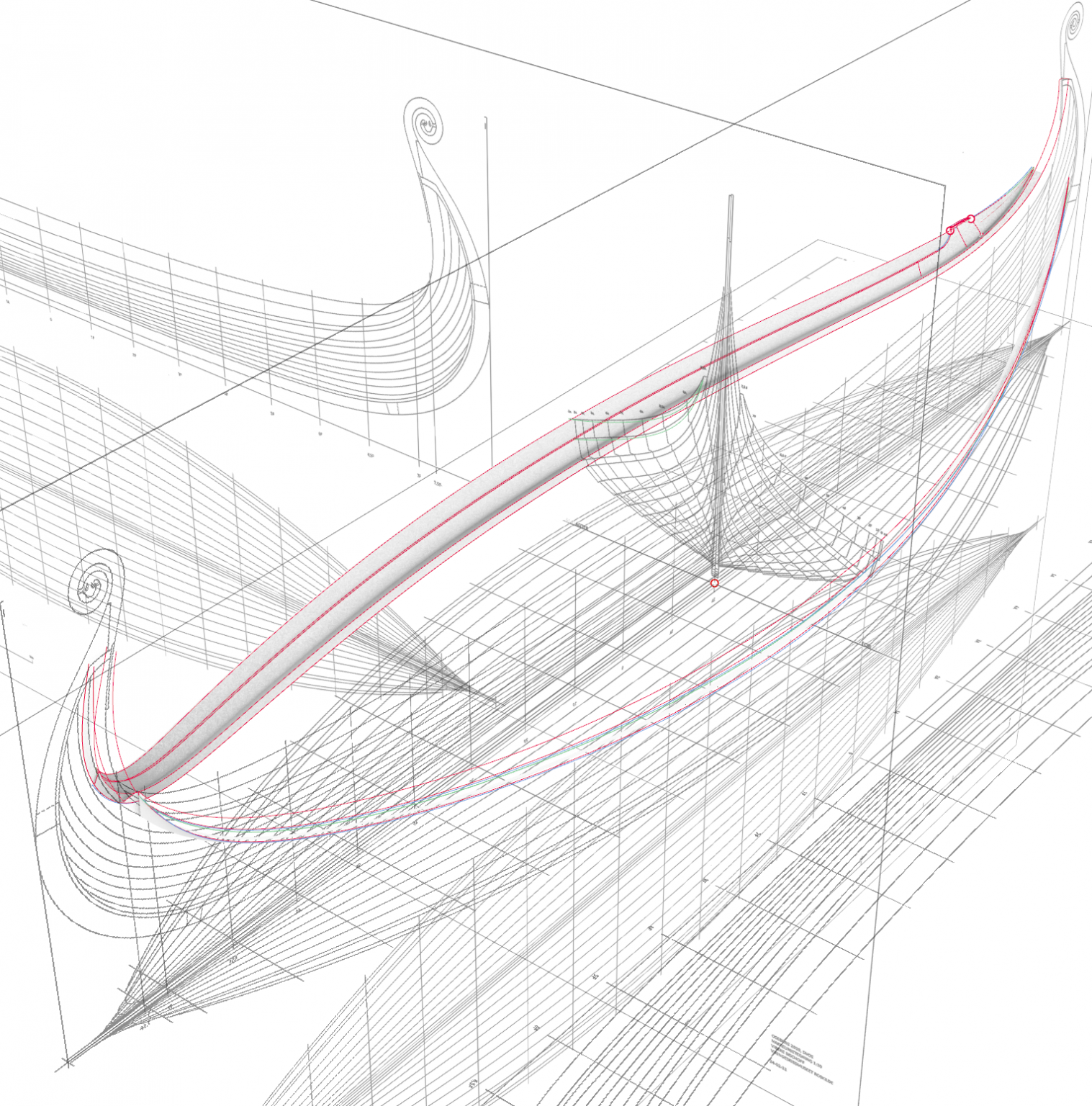
@mtaylor, I know I'll be fine once I get used to it. At this point it's starting to feel like I'm just putting off cutting new wooden parts, the more I get into the smaller and smaller details in the CAD. @AnobiumPunctatum, A couple pages ago in this thread we discussed the pros and cons of doing the frames perpendicular to the centerline. I opted to do them perpendicular both vertically and longitudinally to make designing easier. I'm certain the diagonal frames in the original served some purpose, but this is a model and just needs to float for a little while. I'll try for complete historical accuracy on another model. The frame I've modeled in the images above is 1A in the the Saga Oseberg plans. It's the only one I could find plans for, which I took a screenshot of from one of the video lectures by Vibeke Bischoff on the Viking Ship Museum website. It's one frame aft of frame 0, and the mastfish covers both of them. The vertical deck beam support is only there to test out how it looks with one in place. I'll be removing it when I add the mastfish. I haven't drawn the plank clamps yet. I'll be adding those soon. At the moment I'm still trying to find some rhyme or reason as to how tall and how wide they are. It seems to vary, even on this one frame. I'm using Rhinoceros.
-
I figured out the problem with my top two strakes. I'd apparently dragged them out of position at some point without realizing it. Here's the corrected version with the frame in place. The knees fit much better now.

-
Ha! I wish! I’d totally go that route if I had the money for it, or the time to build one. I’ll have to make do with printing paper templates and cutting everything by hand. 😆
-
@PhilB, I've been a software engineer my entire adult life. Solving things using software comes naturally to me. Solving things in wood using my "mark one eyeballs" is what gives me the willies.
-
I've completed drawing one test frame! My top two strakes don't quite line up so I'll have to do some troubleshooting on those. I will take all of your jig suggestions together and come up with a new jig over the next couple days. I'm getting so close I can smell the future sawdust from here!
-
Actually, it is! Some 3D printers can be configured to use something like a mixture of sawdust and wood glue to make a particle board in any shape desired. I’ve even seen ones that simulate wood grain.
-
Thanks for the great ideas, everyone! The screwed down bulkheads are a great idea! I do have a baseboard but taller bulkheads will be tricky. My little table mounted jigsaw's guide rail only goes out to 6 inches so cutting a straight line any further out than that is near impossible. I don't own a table saw so I can't make larger ones. I was thinking I'd just stack 2x4's on my baseboard on either side of the keel up to the height of my bulkheads, but now I'm thinking that might tend to wander a bit. I'll have to think on that. @AnobiumPunctatum By "stepped design" do you mean the steps of the bulkheads where the planks fit in? I'll give some thought to curved bulkheads. They'd definitely be easier to cut out. At this point I'm starting to lean toward just making my permanent frames and gluing them to the keel before planking. I know that's not how the Vikings built their ships, but it might be easier in the long run.
-
Regarding sails, one of the videos by Vibeke Bischoff, the reconstructor that designed Saga Oseberg, on the Viking Ship Museum website has pretty detailed sail and rigging plans. I forget which one it was but they're worth watching for anyone building an Oseberg model: https://webtv.vikingeskibsmuseet.dk/?poditemid=34285&tagsid=121&soegeord= There's also a video By Thomas Finderup about the building of Saga Oseberg in there.
-
I've run into a problem designing the new jig. This thing is going to need to be removable once I get the planks in place. At that point I'll be replacing the bulkheads with the actual frames. The curve of the stems will prevent removing this in one piece. In my last attempt at a building jig I thought to get around this by building the jig in three parts so that the center could lift up and then the ends could be pulled out separately. This meant that the three parts weren't really attached though and it didn't really stay all that well aligned. I also had a false keel that required a cutout along the bottoms of the bulkheads, which destroyed the notches for the first couple strakes. In these two images I've got my bulkheads, keel, and a cutout for the Hahn method @mtaylor suggested so I can see how it would work if I were to go that route. I'm not sure how I'd keep the temporary bulkheads lined up along the bottom since they're not going to be glued to the keel. Any ideas?
-
Not much to show at the moment. I'm still in the process of designing the new building jig. I'm currently halfway through the new planking bulkheads. It's somewhat on the time consuming side of things, but I'm very happy with the progress so far. This time around, I've drawn the thickness of the bulkheads so I don't end up trying to bend planks around only one edge of the bulkheads like I did last time. I hope to finish drawing the bulkheads tonight after work, and then I'll move on to drawing a frame for the jig to hold the keel and bulkheads in place. After that I can get back into the wood! There's a light at the end of the CAD tunnel now!
-
It's a good thing I didn't throw my laptop in frustration because it turned out I still had the missing lines in my very last save. I now have the insides of the top two strakes fully modeled and ready for printing to templates! Next up, designing new planking bulkheads and building jig.
-
Minor update... I had painstakingly redrawn my top two strakes, because the planking diagram only has the starboard side and the two sides need to be proportional, and because I'm going to need to be able to eventually draw the frames to the inside of the planks, but the lines drawing for Saga Oseberg is only the PORT side. It took weeks but I finally ended up with beautifully curving, flattenable surfaces from which I could print a new planking diagram for these strakes... Then, just as I was congratulating myself for a job well done, I realized I'd drawn them along the OUTSIDES of the planks, and because of this they no longer lined up with the lower 10 strakes. To make matters worse, I discovered that I'd inadvertently deleted the lines for the INSIDES of my planks at some point. I just about threw my laptop out the window, except that I was already outside, doing my CAD work on the porch. Weeks of work gone. On the bright side I picked up the habit of making iterative saves periodically when I used to work as a videogame artist, so I likely have the true inner lines in one of them. I'll just have to dig through each save until I find the most recent one that still has them. Back to the grindestone...
-
This comment made my day this morning, just about died laughing because I know for a fact I'm going to have some similar "conversations" with my own Oseberg.
-
@Binho, That's very interesting! I didn't know about the new Skuldelev 1 reconstruction. In my opinion, after a year of poring over all publicly available research material I could find on Viking ships, the newer one looks a LOT more accurate to me given the hull shape in relation to the flow of the planks. The Danish stem gave the original reconstruction a very low profile and a bit of a stretched look. I'd wondered before how it could have possibly been an effective ship with such proportions. The newer one looks like it has a rounder hull that could handle much rougher seas.
-
@Hellmuht Schrader, no problem, sharing is half the fun! By the way, where did you find that photo of Saga Oseberg under construction? I didn't have that photo yet so it'll be very helpful when I get to that part! Thanks, Kris
-
Hi @Hellmuht Schrader, Do you mean the way the planks curve into the bow? The photo of the second strake being attached when Saga Oseberg was built shows how it was done for the Oseberg ship. The flow of the garboard strake defines all the curves of the planks above it. The rabbets for Saga Oseberg were cut to the depth of the plank as each plank was attached. Note the notch cut to just above the second strake where it meets the stem. This is only one method the Vikings used. Others used the method shown in your other images, where the stem was cut with faux planks carved into the stem itself. The planks were then fitted to line up exactly with the faux planks. In both methods, the garboard strake and the curves of the stems determine the shape of the hull. There is no need to worry about how to curve the planks. As long as they are cut to the right shape, and the garboard and stem curves after correct, each plank is simply bent around the one below it.