Richard44
-
Posts
429 -
Joined
-
Last visited
Content Type
Profiles
Forums
Gallery
Events
Everything posted by Richard44
-
 Chris, Have a look at this site, you may find something of interest. Cheers. https://neptunia-hobbies.com/products--shop--erratas.html
- 106 replies
-
- 2
-

-
- digital navy
- v108
- (and 3 more)
-
Thanks everyone for the comments and the likes. The shipyard is not closing but it will be awhile before there is any activity. Cheers
-
Thanks everybody for the comments and the likes. Cheers
-
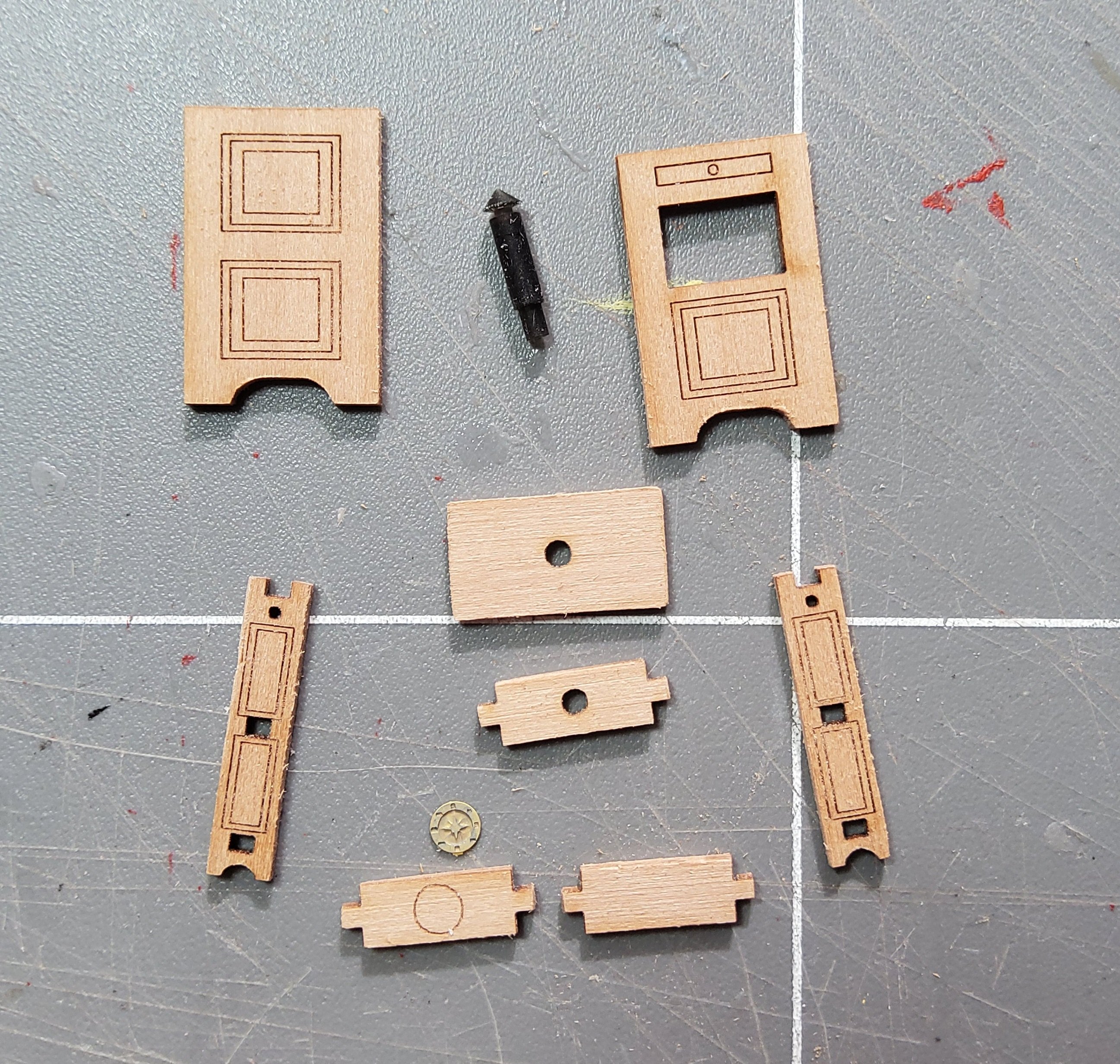
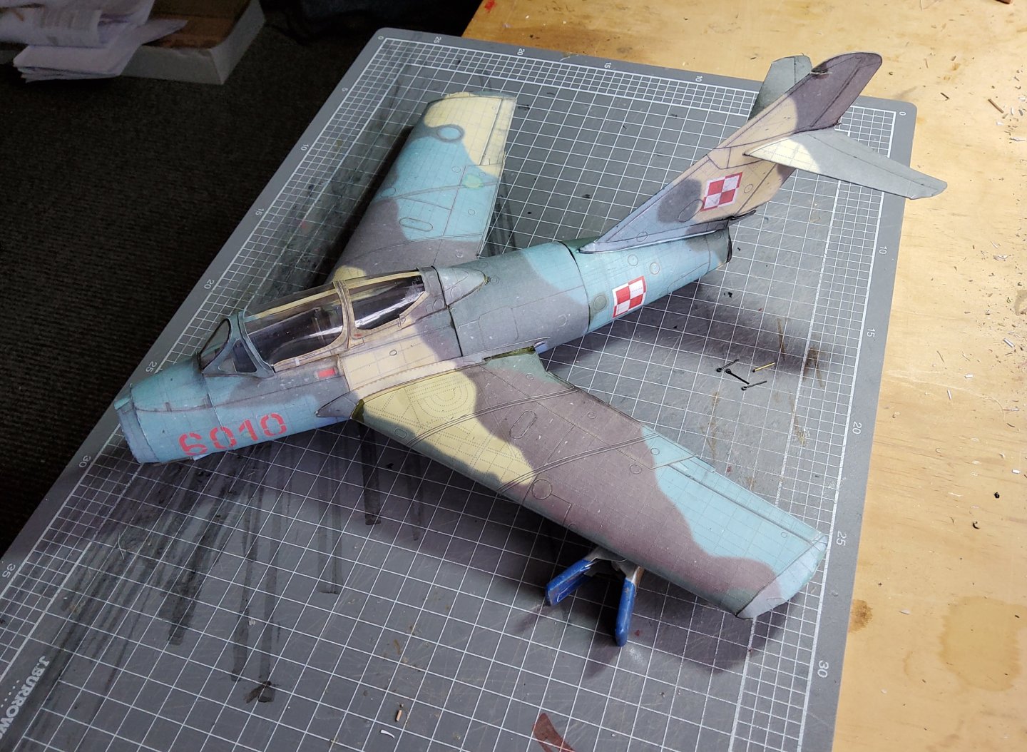
The parts for the undercarriage are shown below. The wheels are partly assembled with a core made from laser-cut pieces and printed facings. There are three parts that have to be formed from wire and many parts that have to be rolled into tubes. The larger tubes are only about 2mm in diameter and were formed using delaminated card wrapped around suitable styrene tubes. Once formed these were then slipped over the wire cores. The smaller tubes were made by wrapping the delaminated card around styrene rod. The wire cores were supposed to have been made from 0.5mm diameter wire, which I did not have, so I substituted 1mm wire instead. The main legs didn't give me much of a problem, but the nosewheel leg was a pain and made me think of bining the lot. However. The legs were glued in position, and the smaller tubes added where indicated. The wheelwell doors were then glued in place. There are still some parts which could be added, eg the drop tanks, but I'm calling this build finished. Not a particularly good job, but good practice for the next card model. For those of you who have looked at Chris's model (here), it is readily apparent that his model is of an aircraft that has just been completely restored and is fresh from the maintenance hangar, whereas my model is of an aircraft that is still out in the open and has been for 50 years or more 😁😁. That's it than. And thanks for the comments, likes and visits. Cheers


- 28 replies
-
- 10
-
-
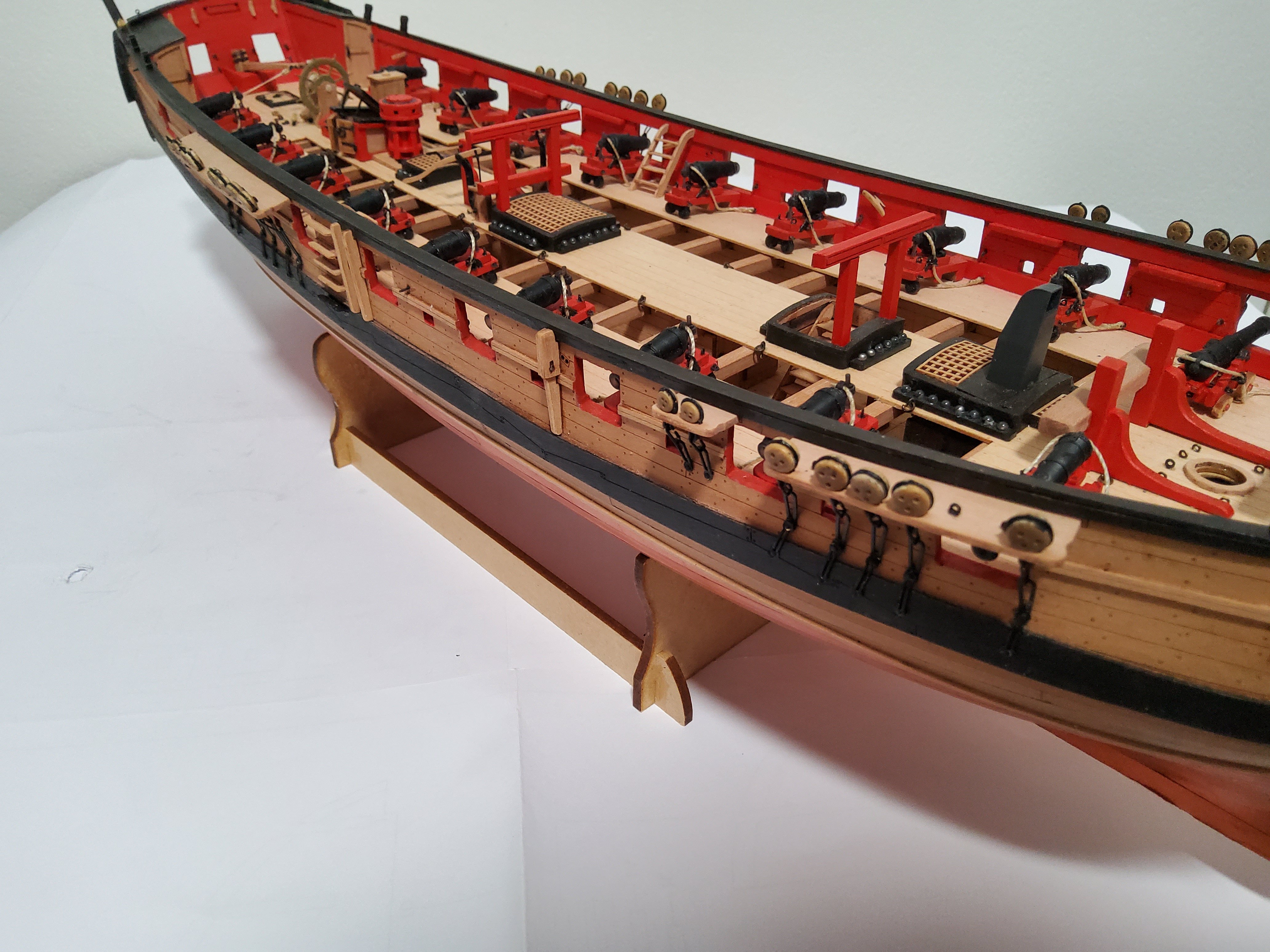
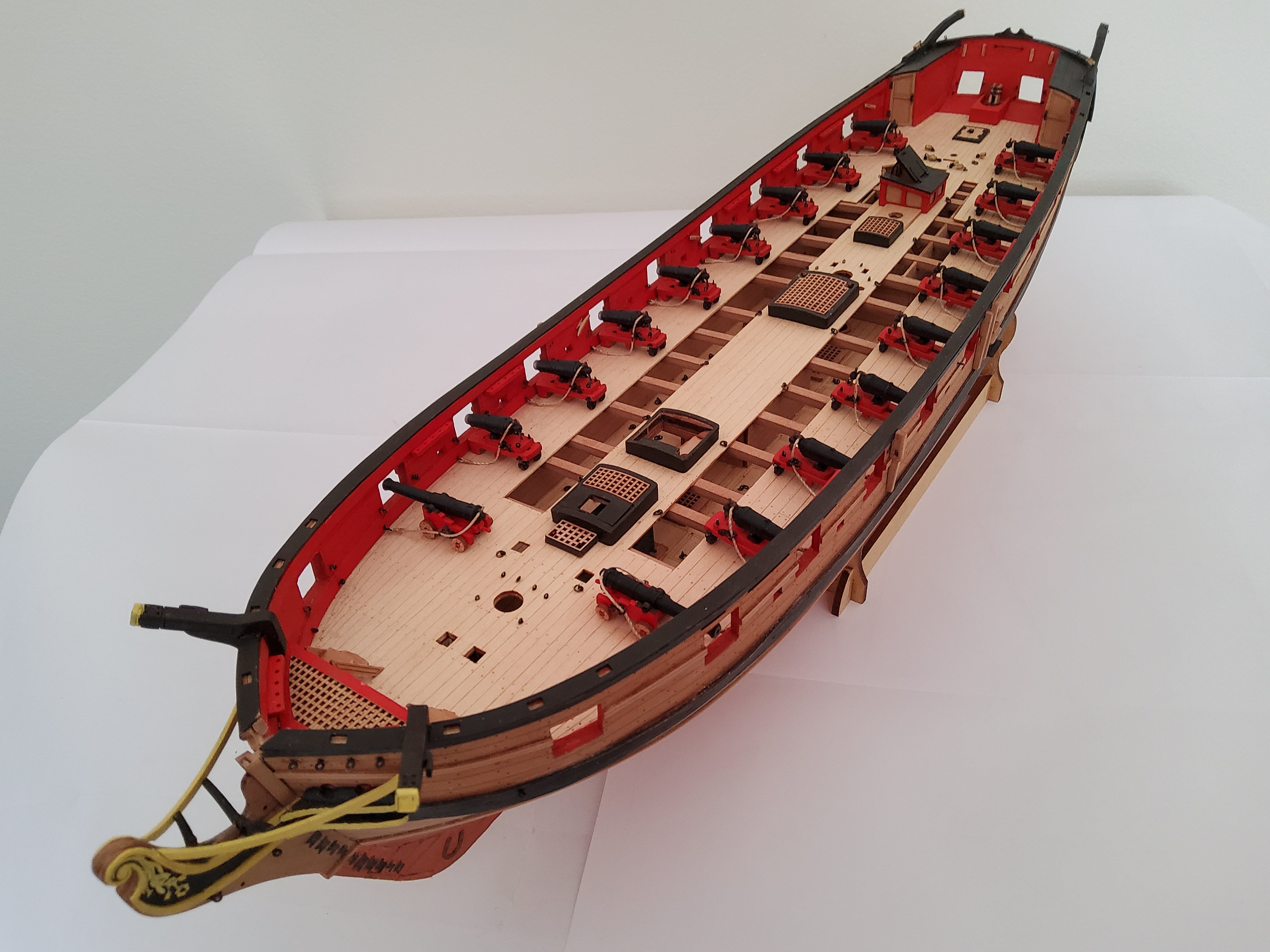
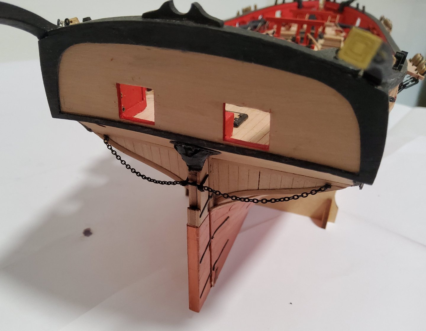
The anchors were next. Only two out of the four that came with the kit were used. As I mentioned in an earlier post, I broke one and couldn't do anything with it. I also inadvertently shortened the fourth one by breaking the end of the shank, but managed to drill a hole to take the ring. But this shortened anchor could not be fitted to the ship as it completely interfered with the chainplates. The two anchors were fitted more or less as the manual showed, even though there is some doubt as to the exact arrangement of the cables. I have looped the cables over the bitts but in reality this would seriously interfer with a lot of rigging. As I explain below, I'm not doing any rigging, so no problem 🥴. So, I have decided to end my build at this point as I'm not going to be doing the masting/rigging. For two reasons. Firstly, I don’t have anywhere to put a fully masted model, nor even a partly masted one such as Blue Ensign is doing, and secondly, at my age (81) I very much doubt that I could keep the enthusiasm up for the three or four months it would take me. Better to stop now at this logical point rather than part way through the masting/rigging. Some final photos. The build has been very enjoyable, and the other build logs have been very helpful (thanks to all). And again thanks to all who commented, liked or just looked in. Finally, thanks to Chris for the wonderful kit. Cheers


-
Anyone out there working on a card model?
Richard44 replied to gagliano1770's topic in Card and Paper Models
If you mean two of the paddlewheelers at Echuca, then I've built two of them, the Alexander Arbuthnot and the Pevensey. Both build logs are linked in my signature. Cheers -
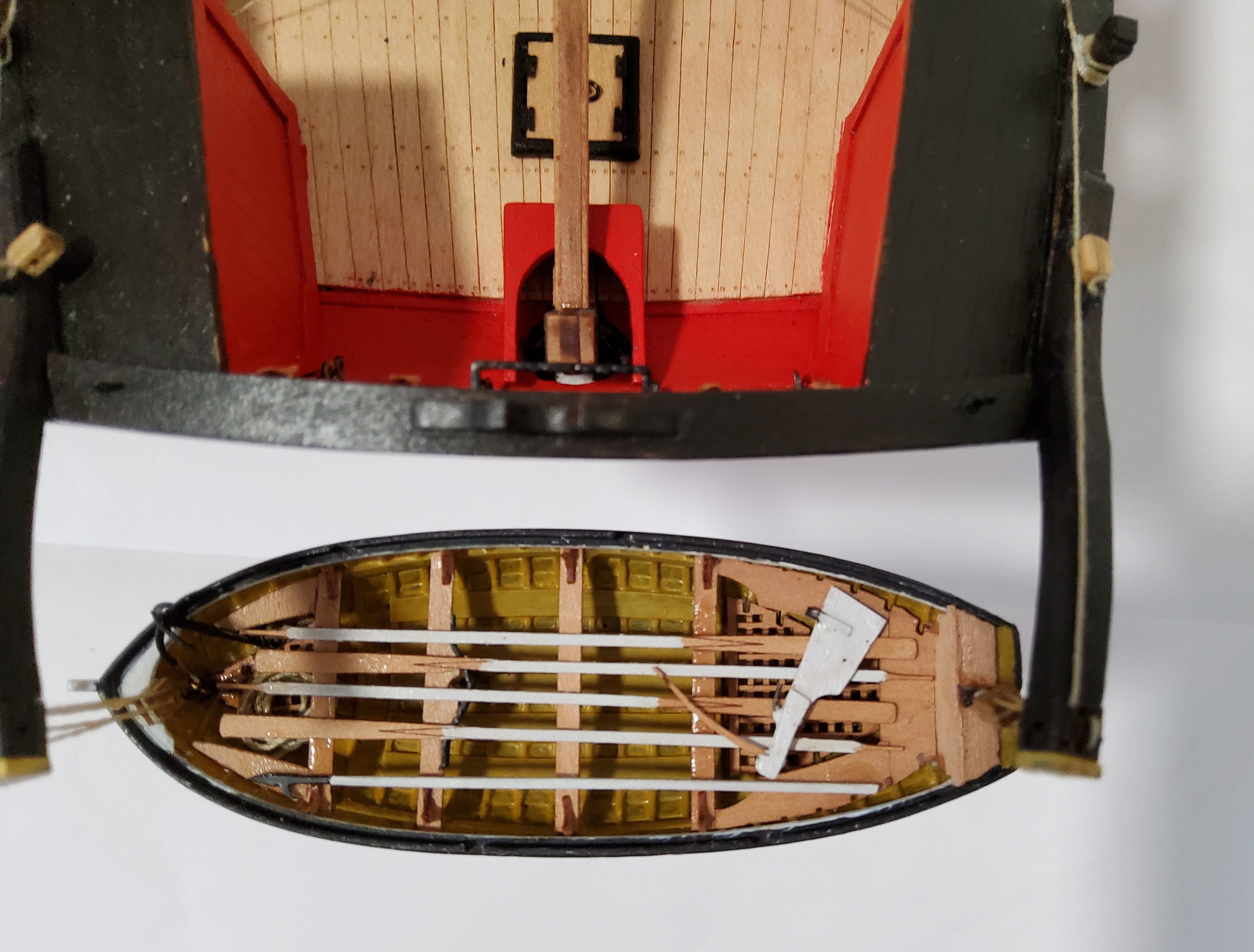
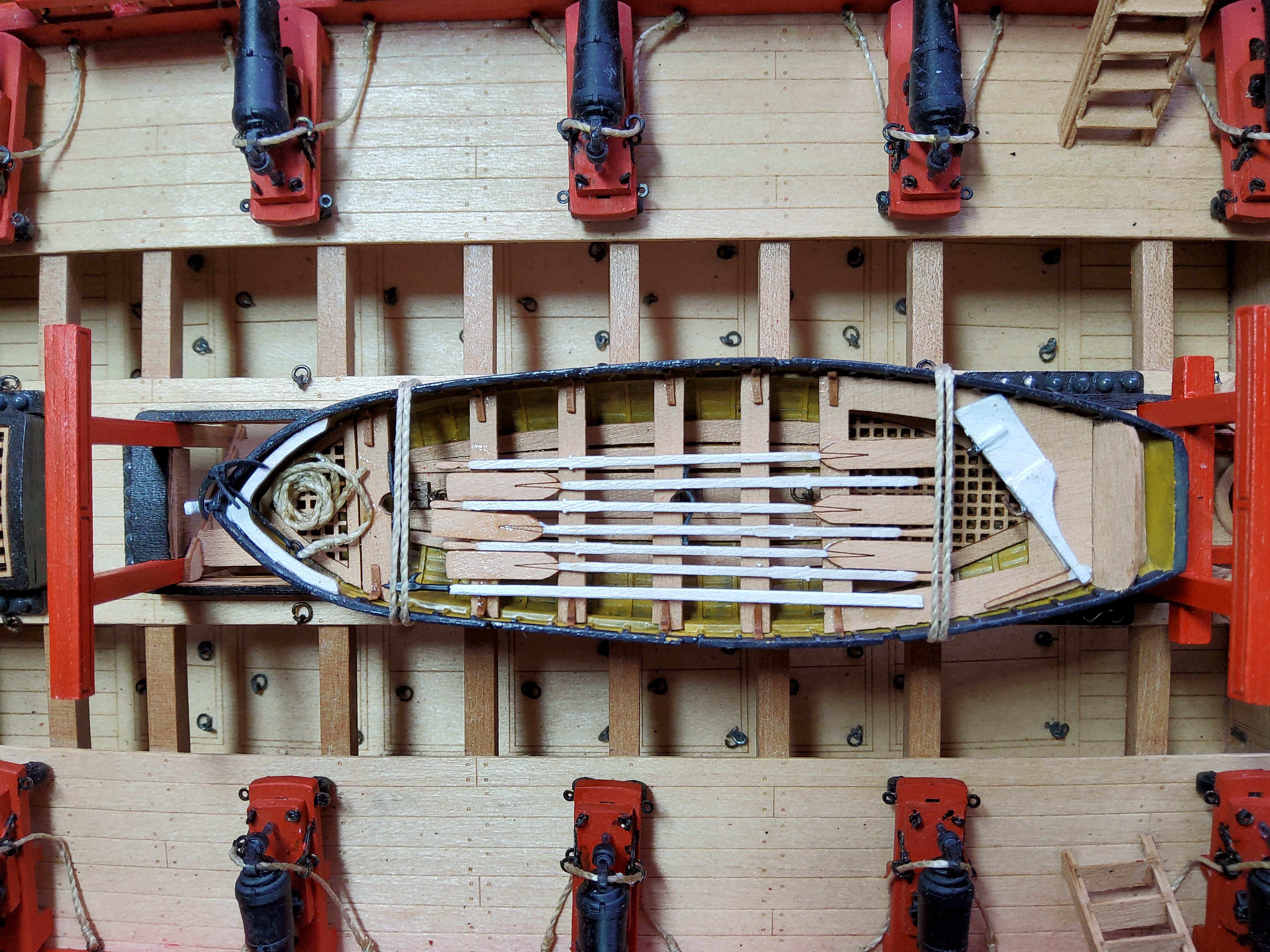
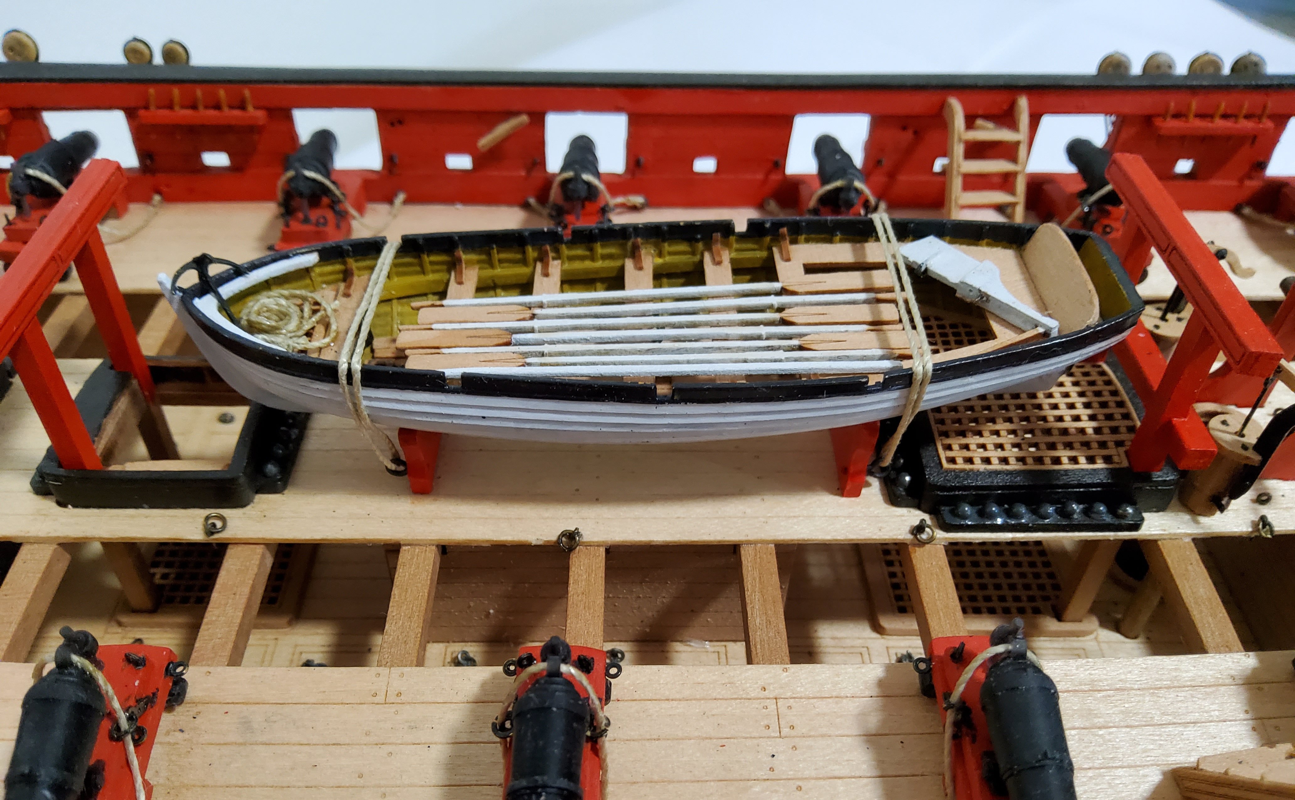
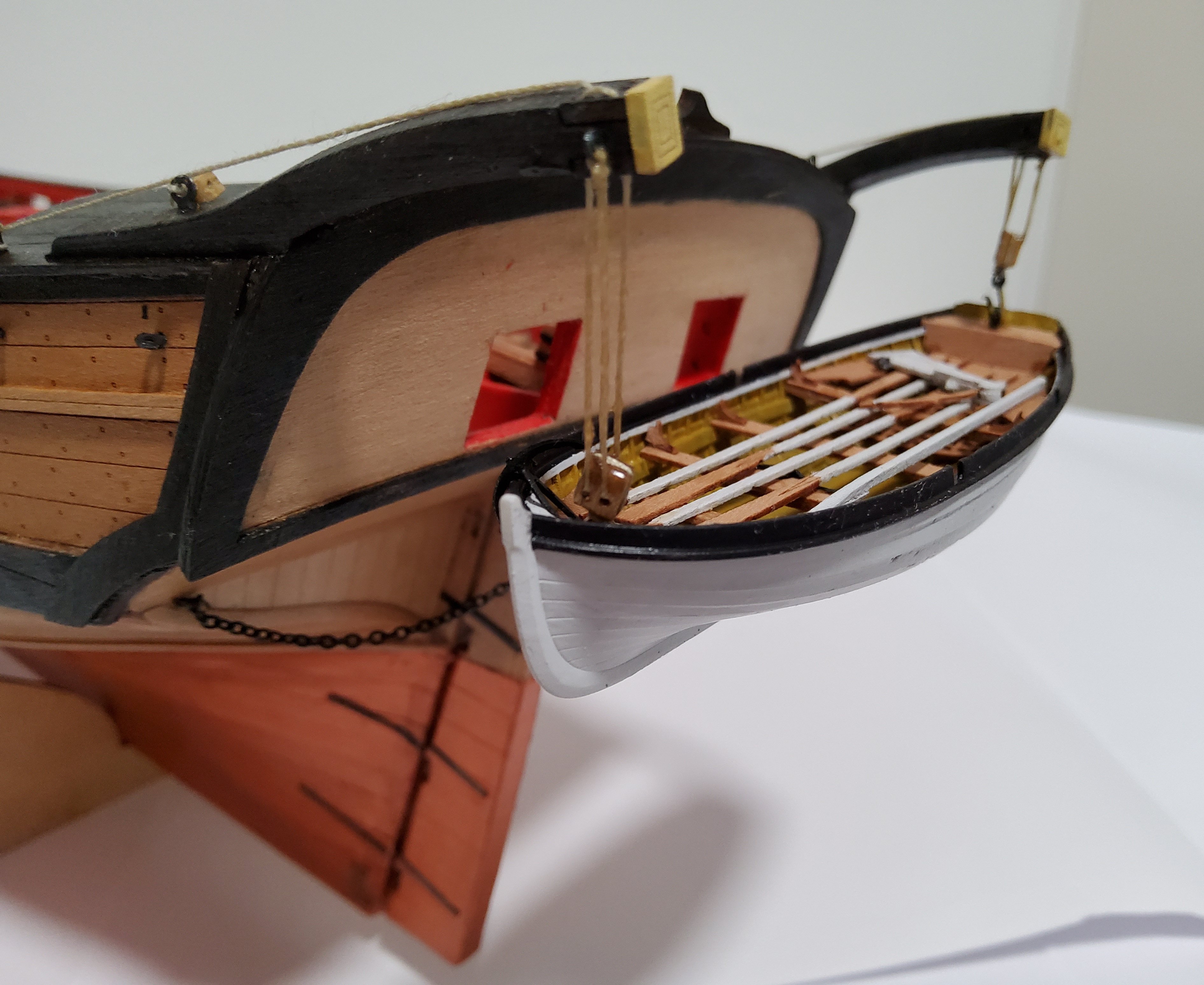
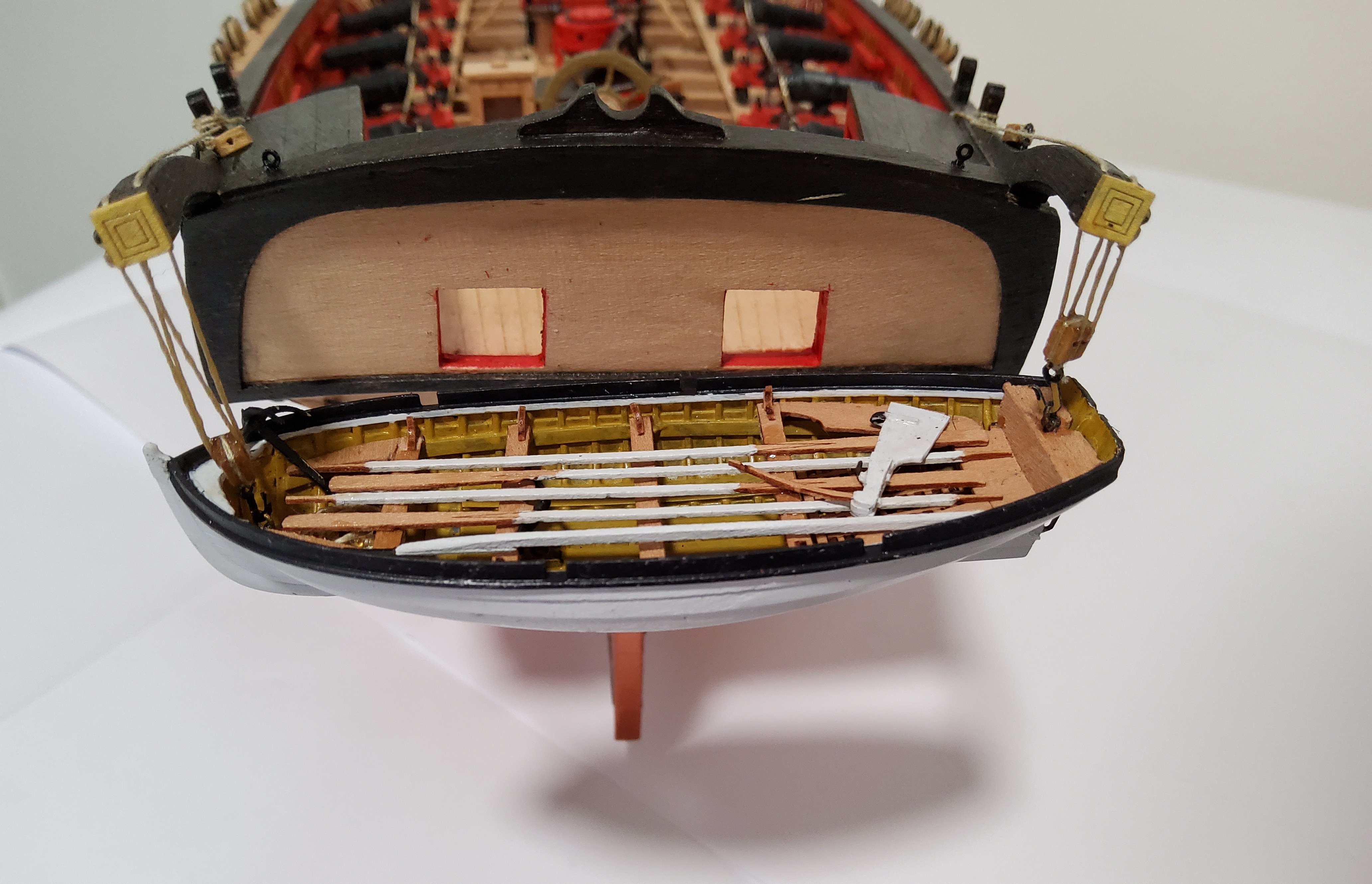
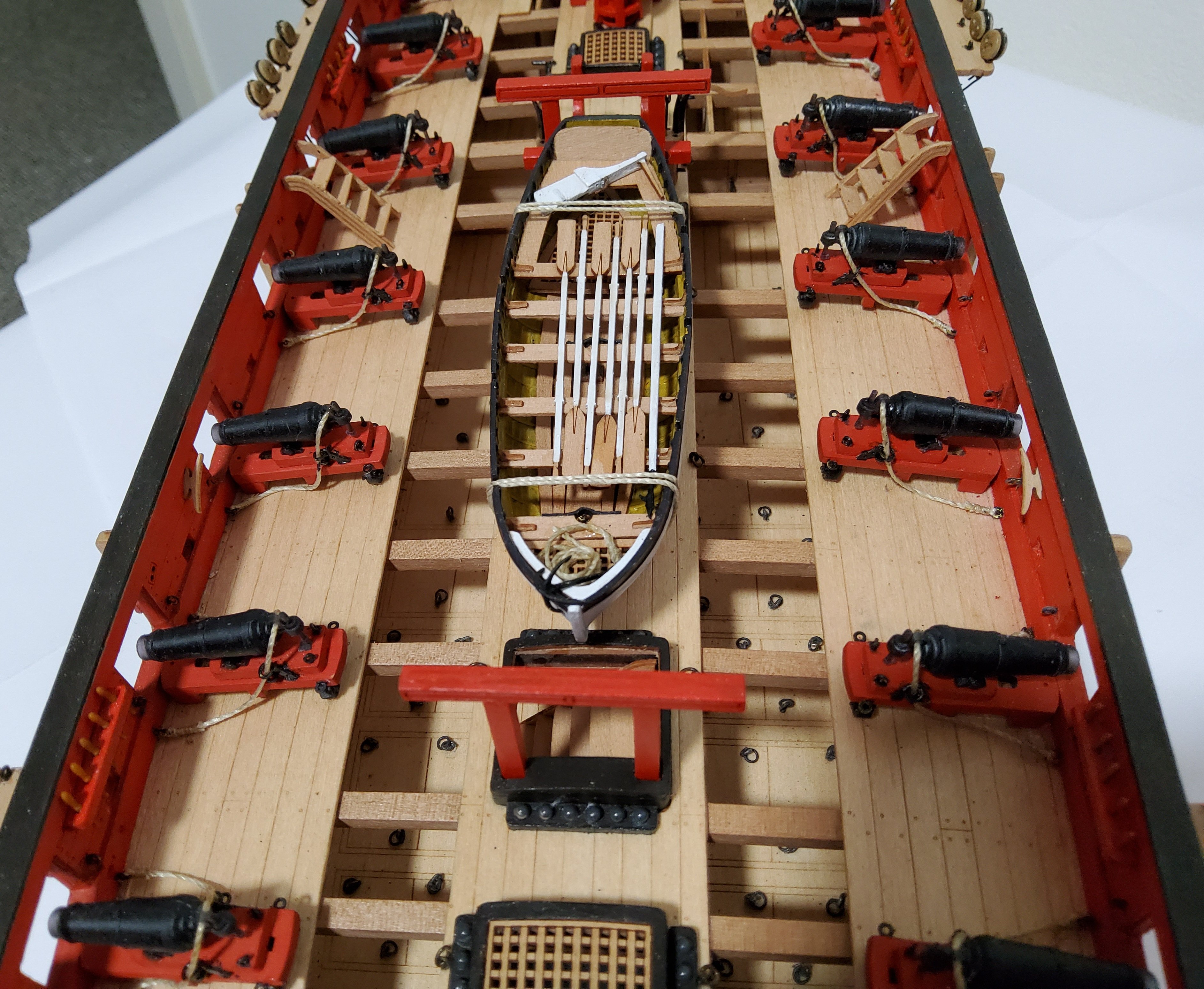
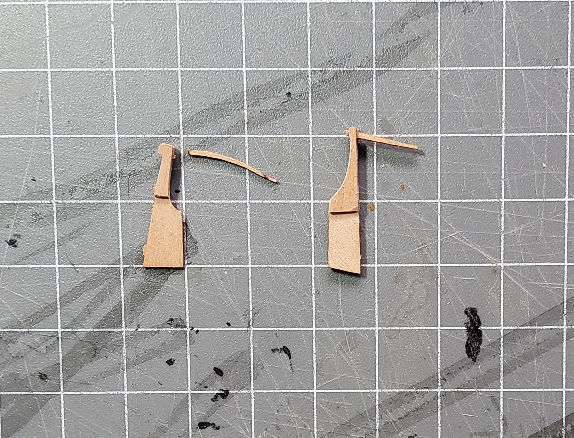
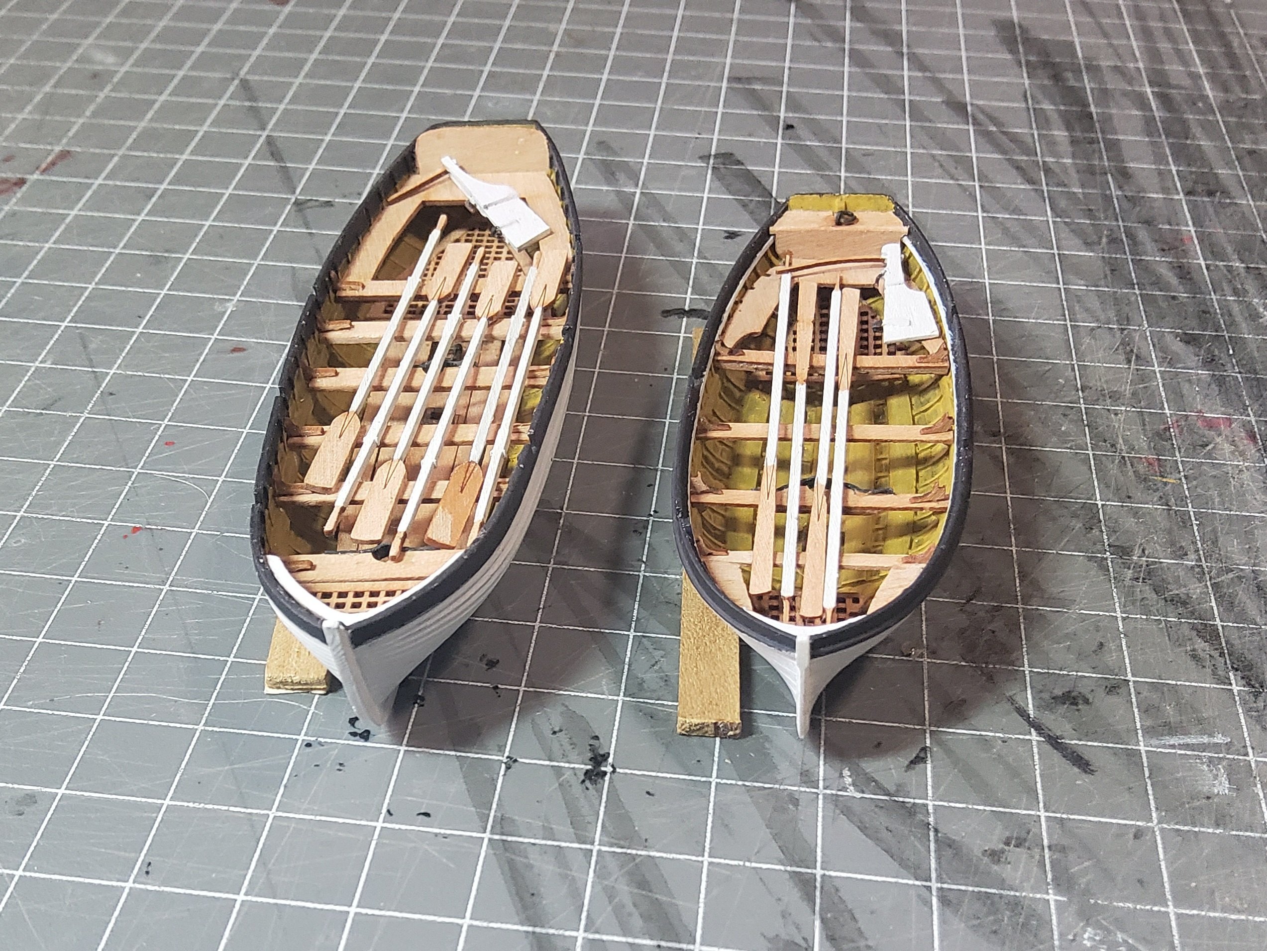
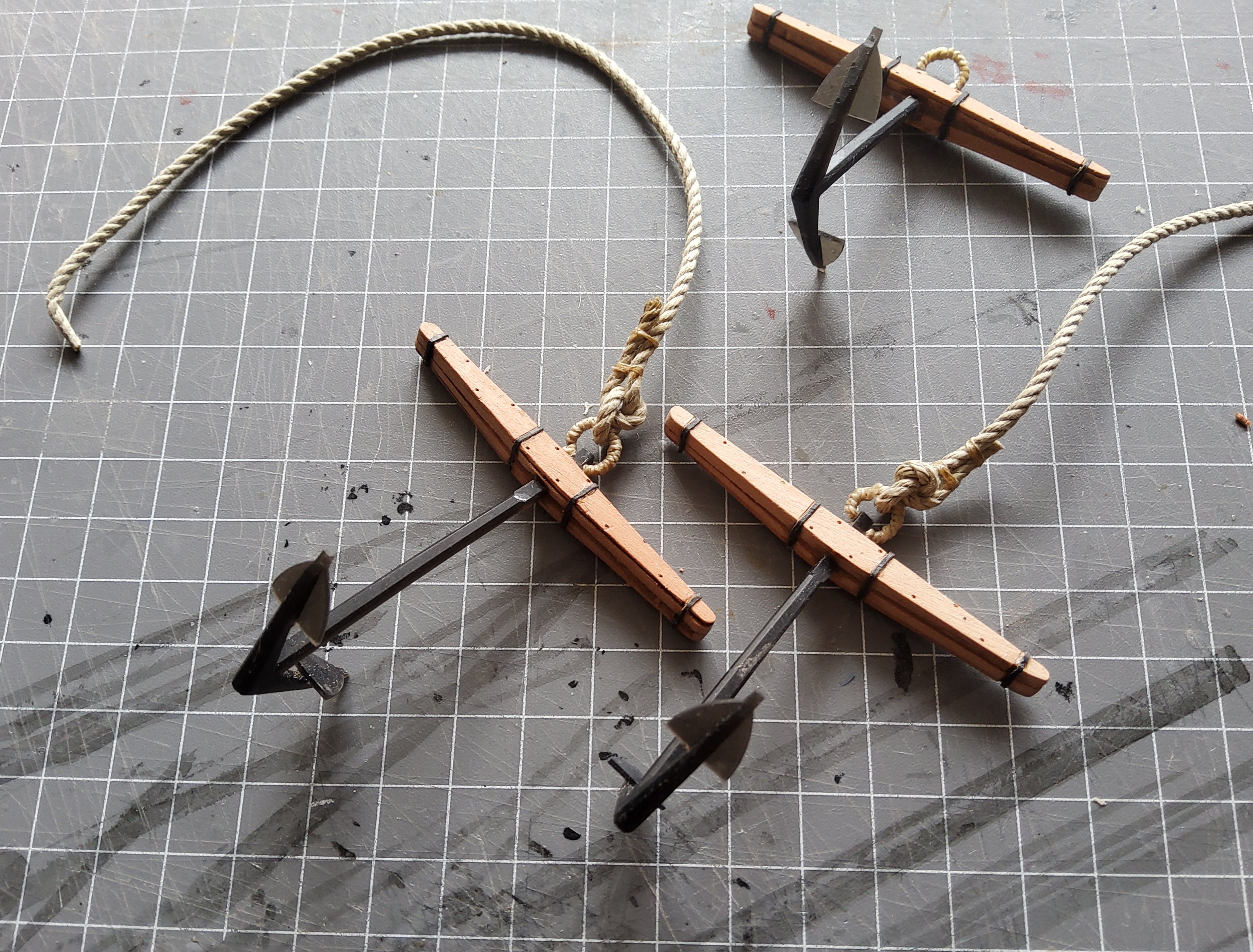
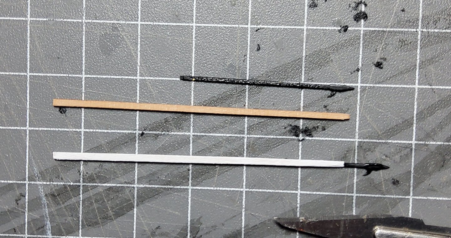
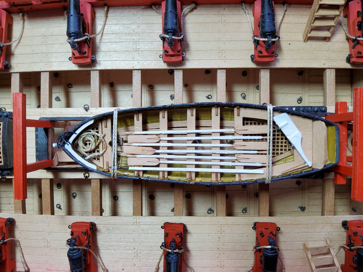
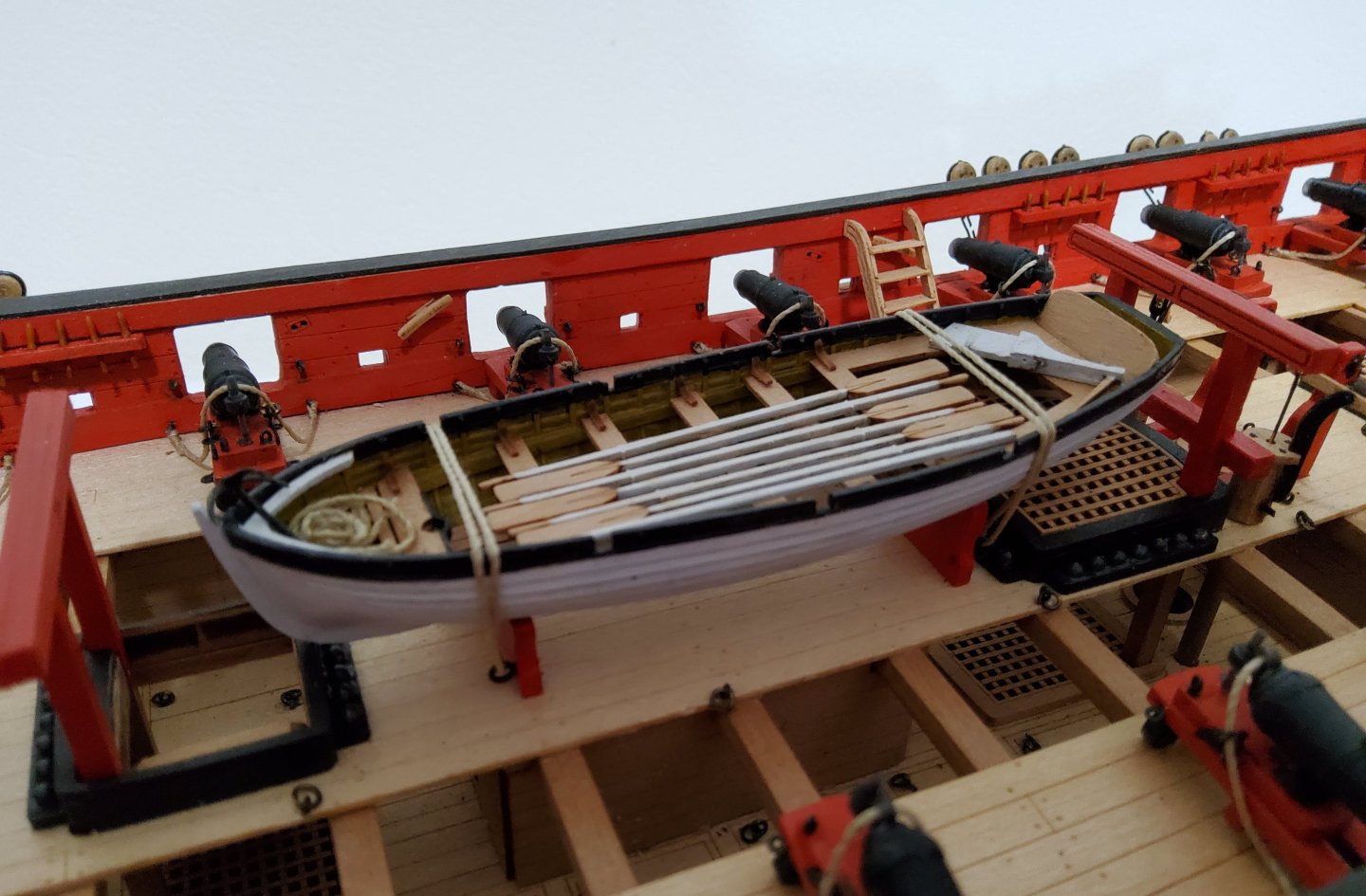
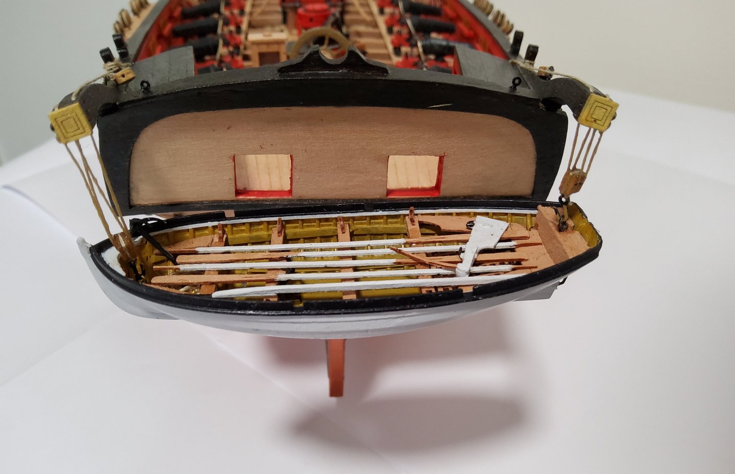
Thanks to all who have commented, liked or just visited. Ship's boats, continued. Two PE grapnel-type anchors were supplied and were assembled. Rings were added to the shanks and a length of rope attached to these. The rope was coiled and the completed anchors placed in the bow of each boat. Two PE boat hooks were also provided, but these were quite short, and so I lengthened them with a piece of 0.6mm pear fret. The photo shows one of the original boat hooks on the top, and a modified one below. The modified ones were placed in the boats. The completed boats were placed on board Harpy, the 22ft cutter lashed down amidships and the 18ft cutter swung from the davits at the stern. I moved the 22ft cutter back somewhat to give better access to the forward ladder. Once I was happy with where the 18ft cutter was hanging, I put a weight in the boat to weigh it down, such that the tackle was taught. PVA glue was then brushed on the tackle, and once dry the weight was removed. The result gives the impression of a heavy boat hanging from the davits. Cheers


-
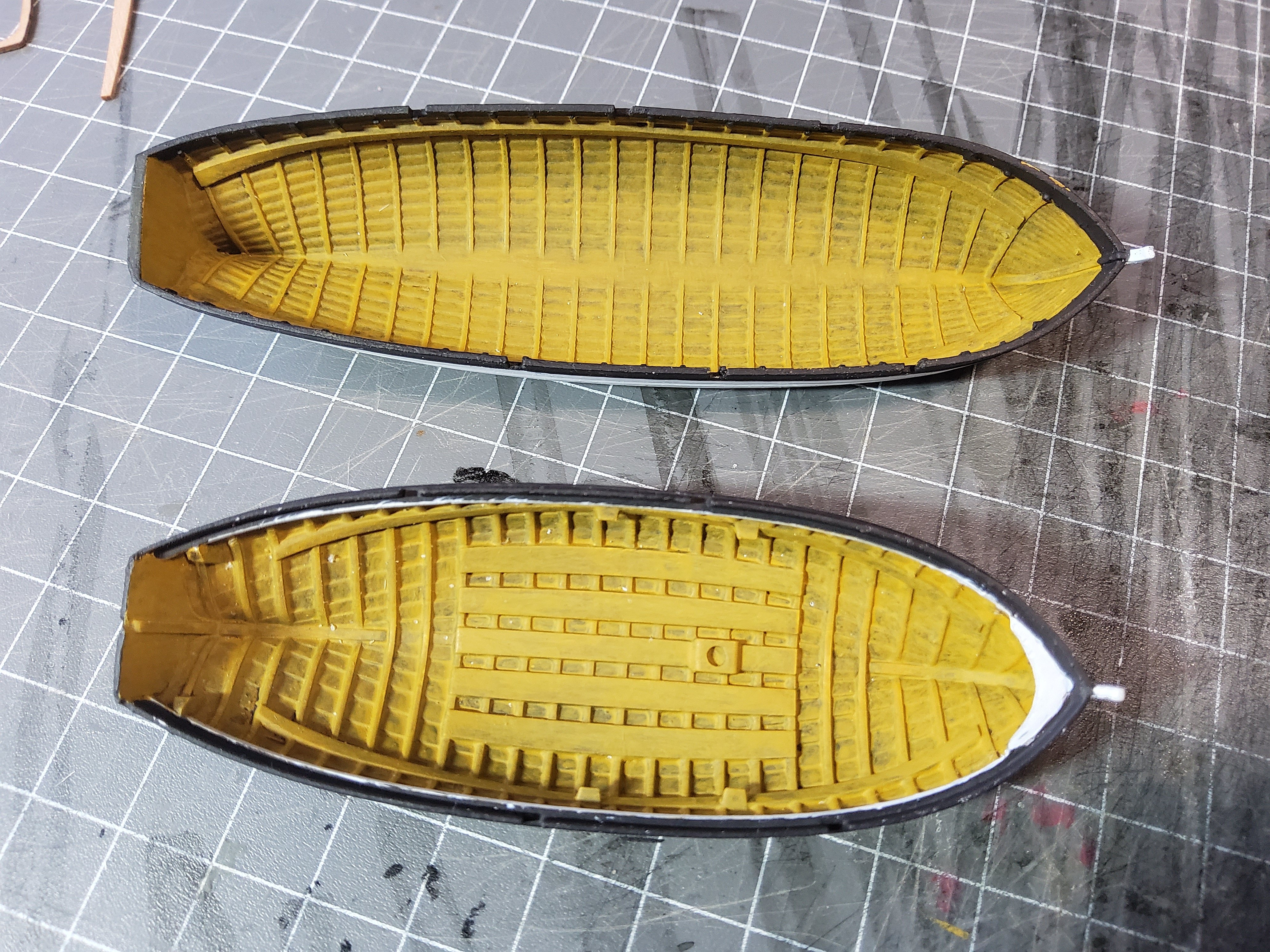
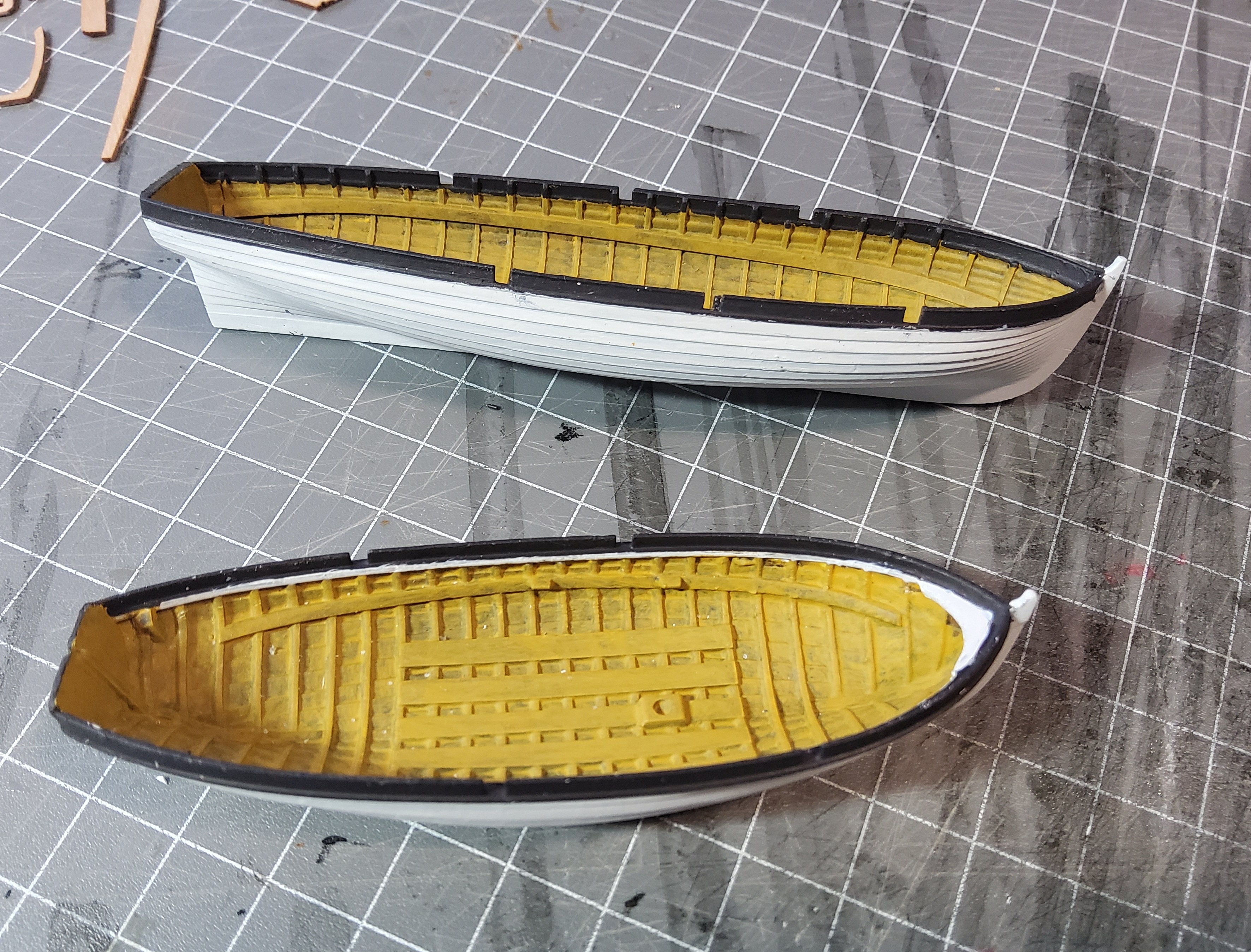
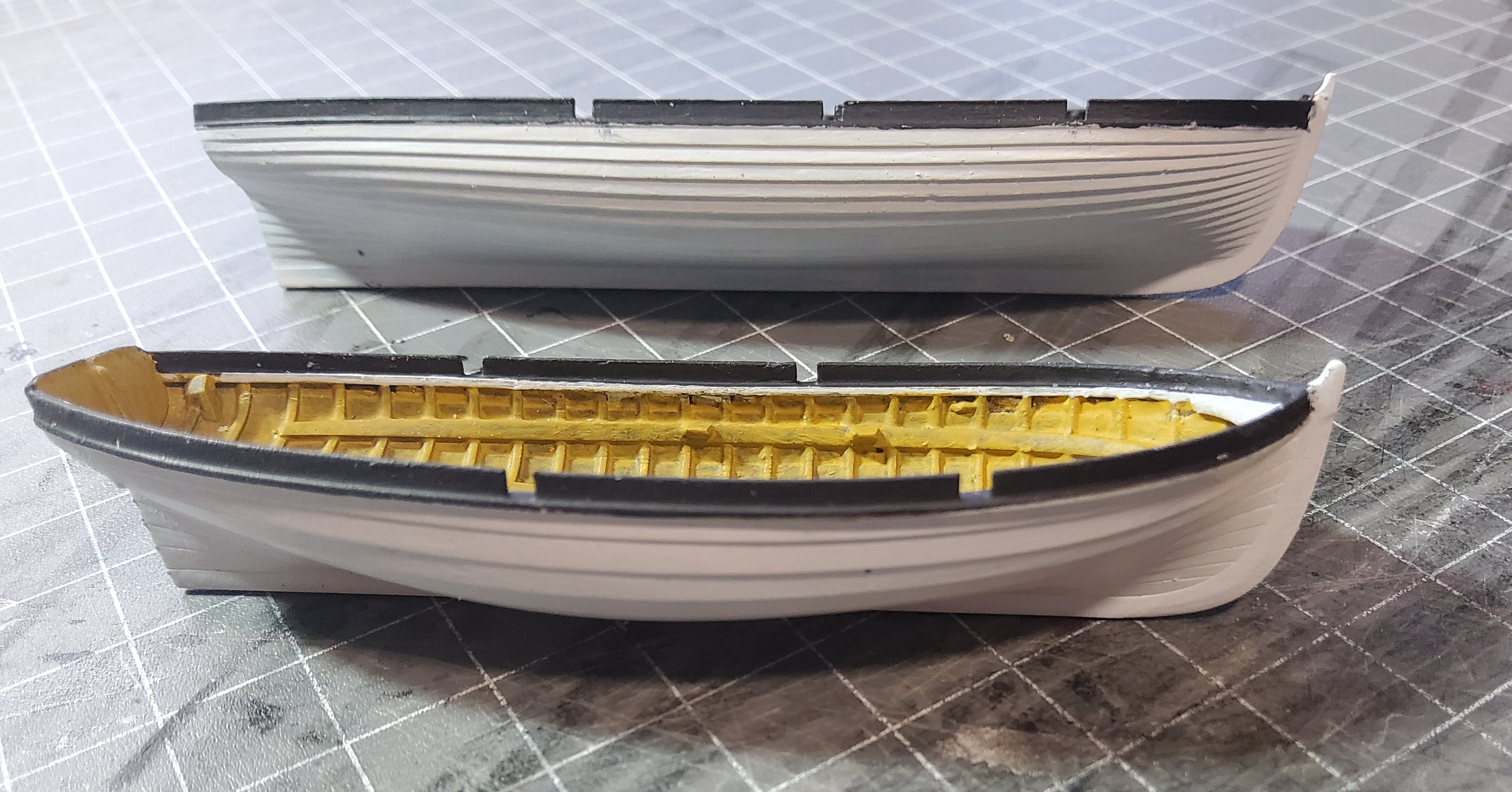
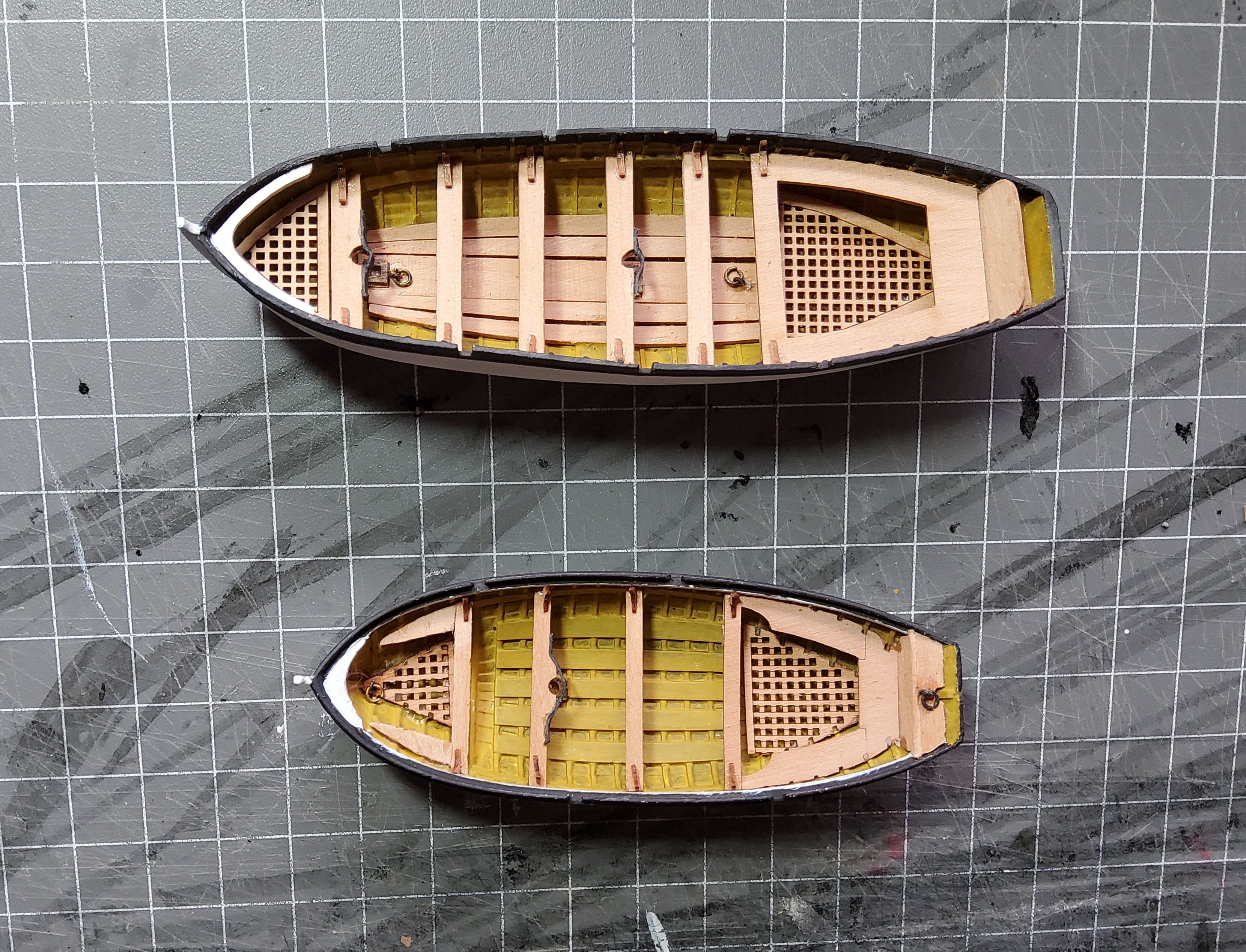
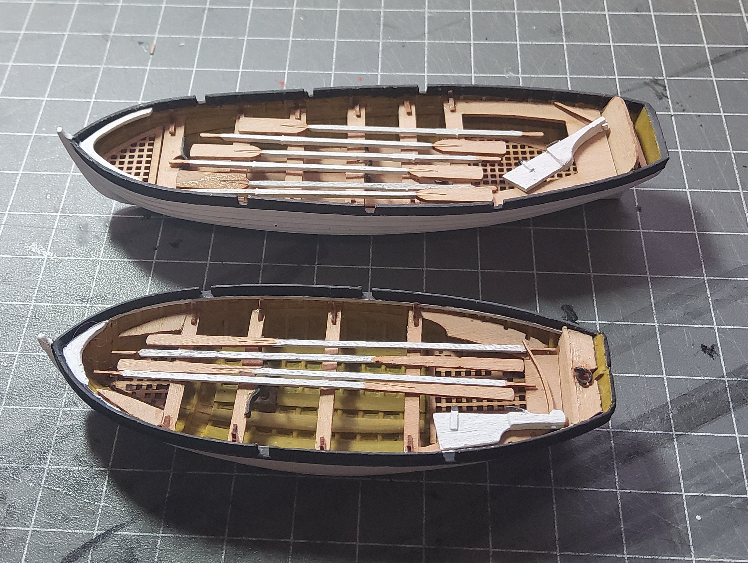
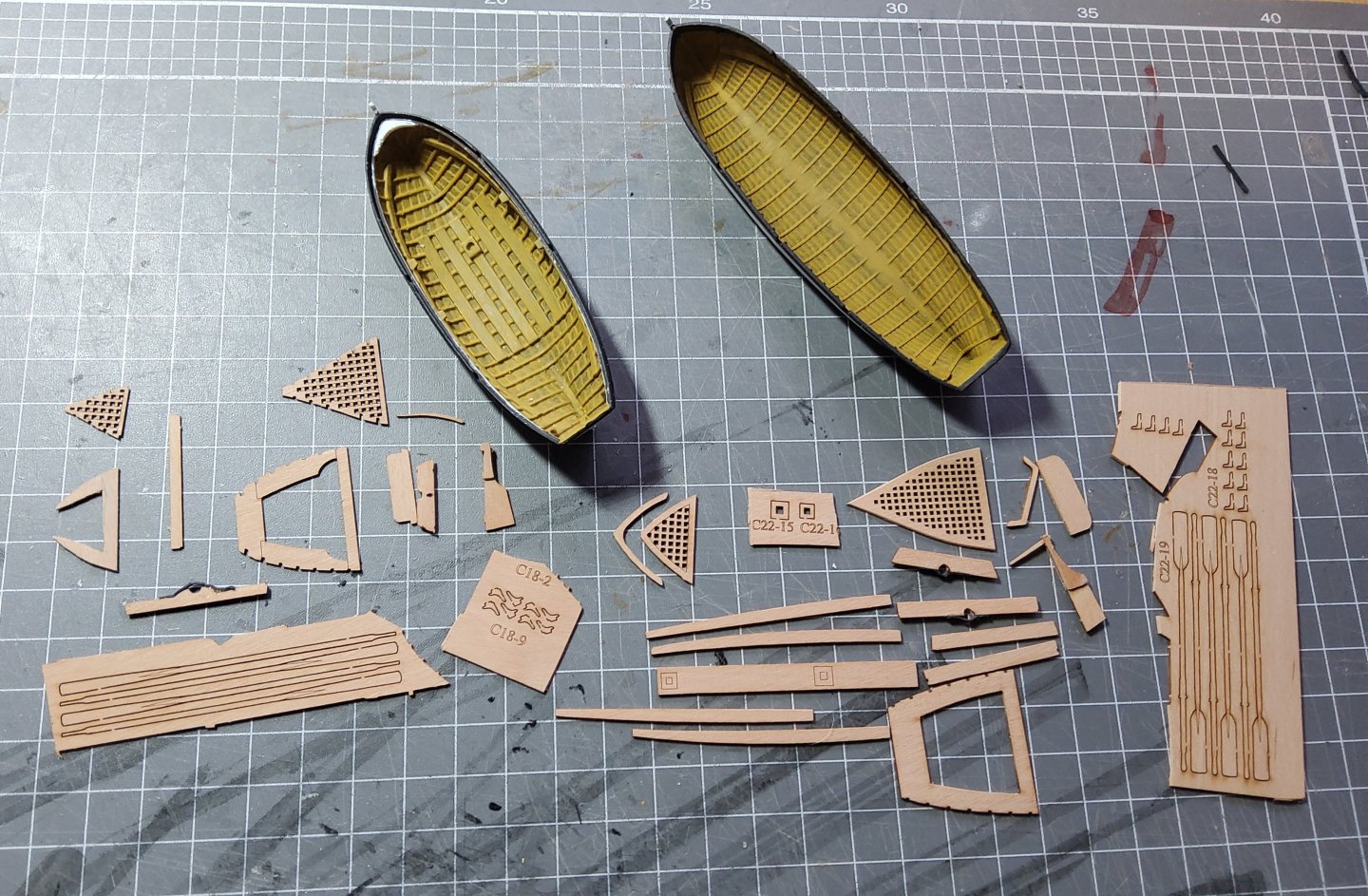
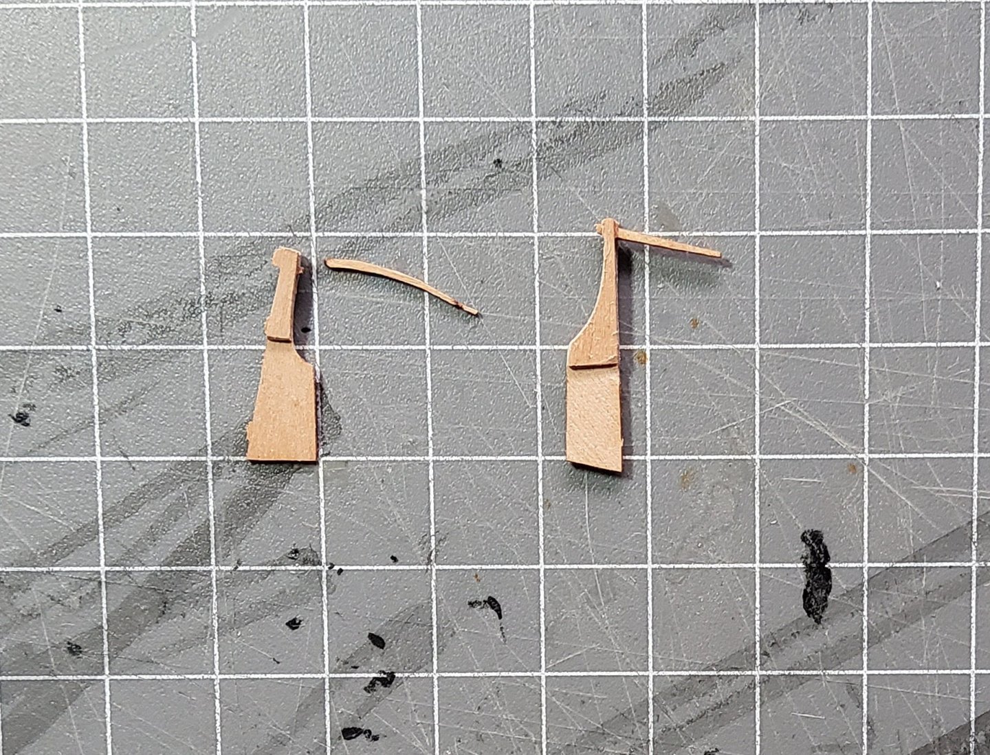
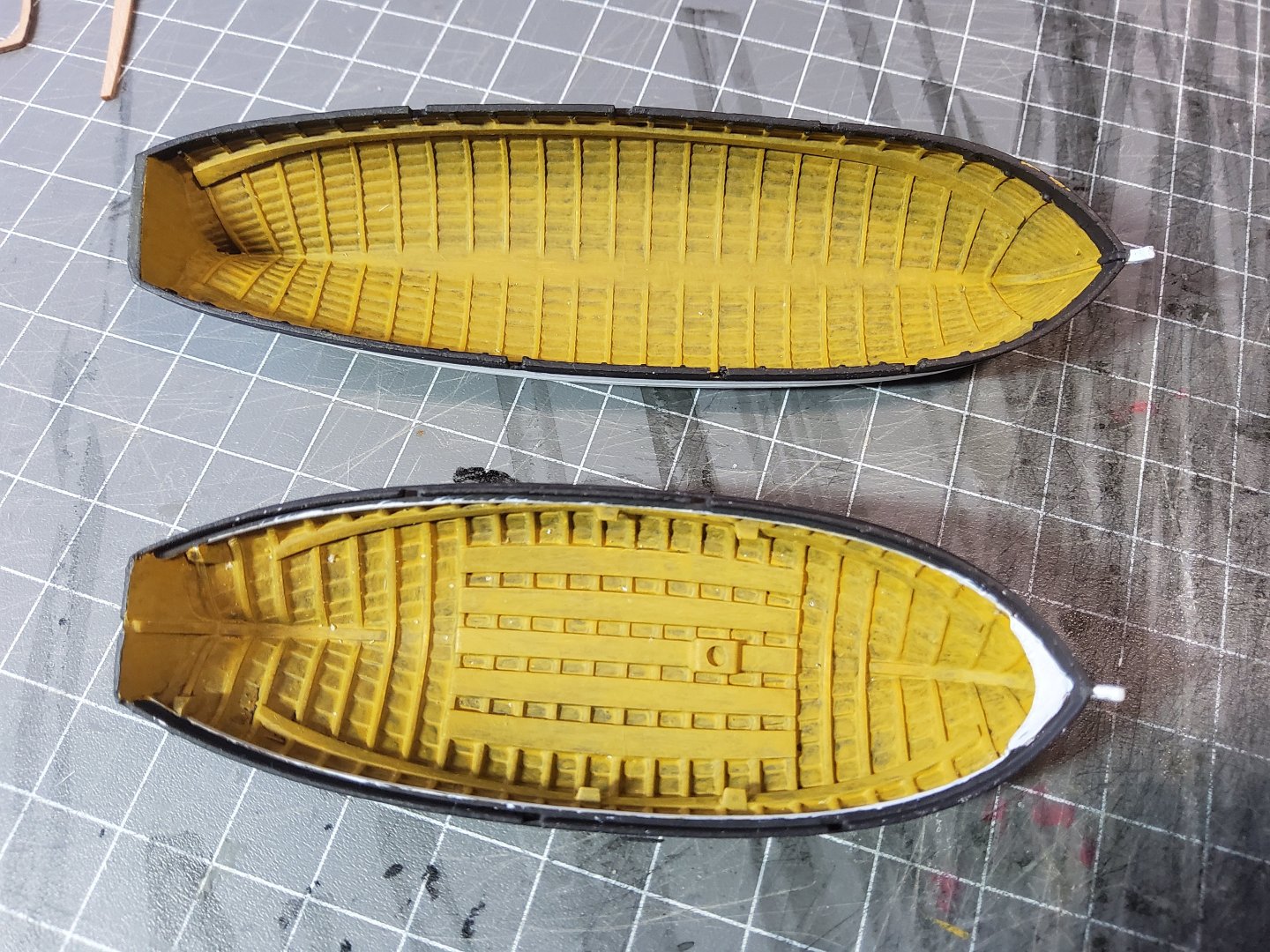
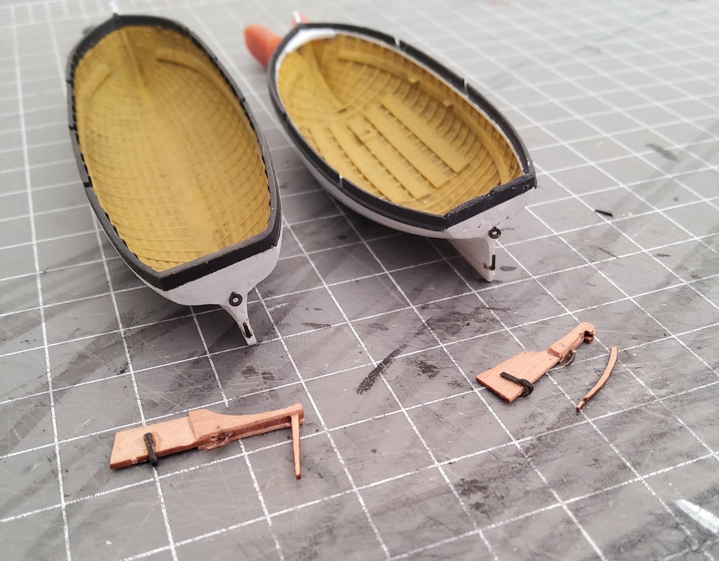
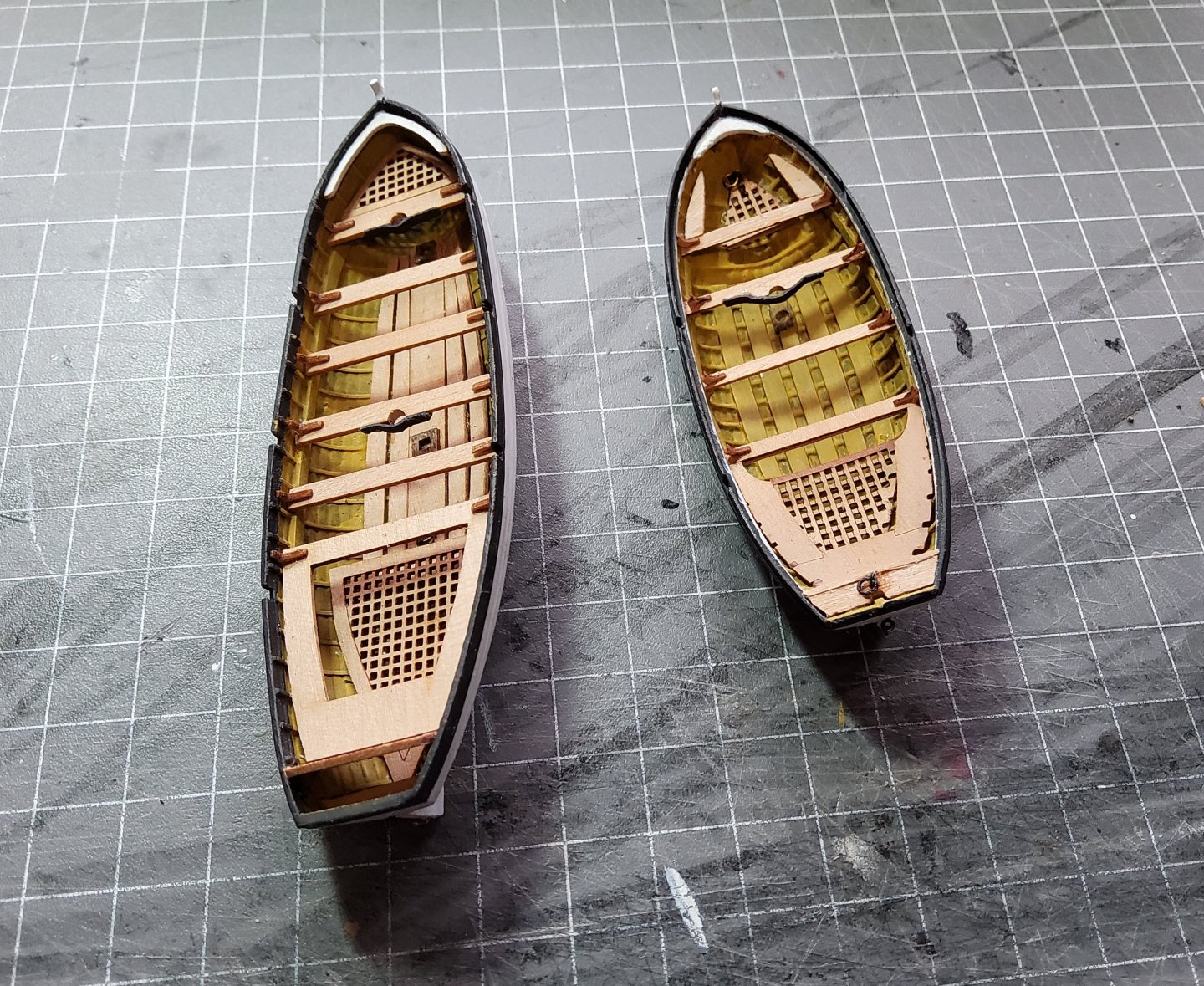
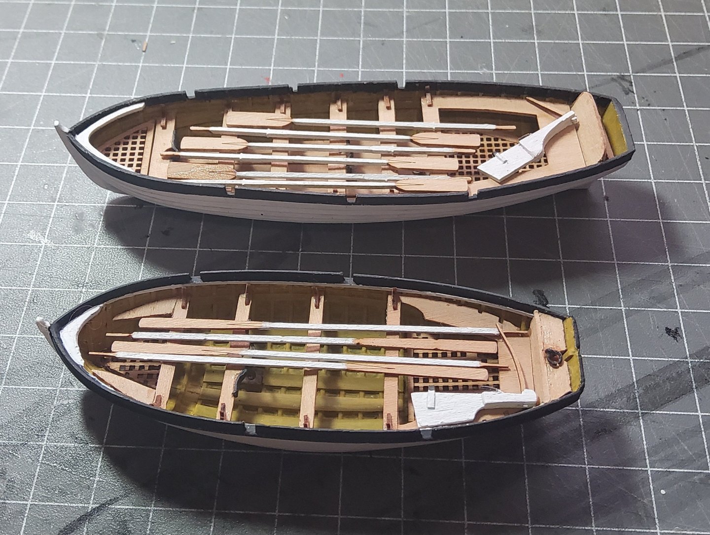
Ship's boats. The two cutters (18ft and 22ft) are very similar, with printed hulls and pear fittings, shown in the photo below. Note that the hulls have already been painted, but more on that in a minute. There is a difference in the rudders. That for the 22ft has the tiller and the blade as one piece whereas that for the 18ft has a seperate, very delicate, tiller, and also has "cheek" pieces either side of the upper blade. I decided to add similar pieces either side of the blade for the 22ft rudder. The two rudders are shown below (the 18ft tiller is on the wrong side). Painting of the hulls. I used an ochre colour for the interiors, then decided to add a darker wash to improve the bland appearance of an all-ochre interior. I copied what Blue Ensign did in his build, but whereas his application was successful, mine was a total failure 😬. I've never used a wash before and unfortunately chose one that was far too dark. So, I let the boats dry thoroughly then went over everything with the ochre again, but this time using an almost-dry brush. Success 😁. The wash is still apparent but much toned down. The outside was painted a slightly off-white colour and black trim was applied inside and out. Pintles and gudgeons were added to each boat/rudder, though the rudders won't be shipped, just lying in the boats. Care had to taken with the pear fittings as some (the gratings) were very fragile, and I actually broke one of the ones for the 18ft cutter. I glued the halves together with some reinforcements, and the break is barely noticeable. The bow thwart for the 18ft had to be cut into three as it was far too big to go into place. The thwart itself was then glued, and the other two pieces trimmed so the they would fit. When building the 22ft cutter, the first piece to be fitted should be the grating in the bow, then the first thwart. This then allows the centre floor piece (which has two mast steps) to be accurately located, using a dowel to position the forward mast step immediately under the thwart. The rearmost thwart in this cutter, while shown on the plan, was missing from the pear sheet, easily fixed with one cut from the fret. Mast clamps, made out of black card, and ringbolts (for lifting) were added to each cutter. Some attempt was made to round off the shafts and handles of the oars, and to thin the tips of the blades, but this quickly came to a stop when the blade of one oar started to split. Finally, a trial fit of the 22ft cutter on Harpy. Notice that the bow of the cutter almost completely blocks access to the ladder (this is also shown in photos in the manual). Cheers


-
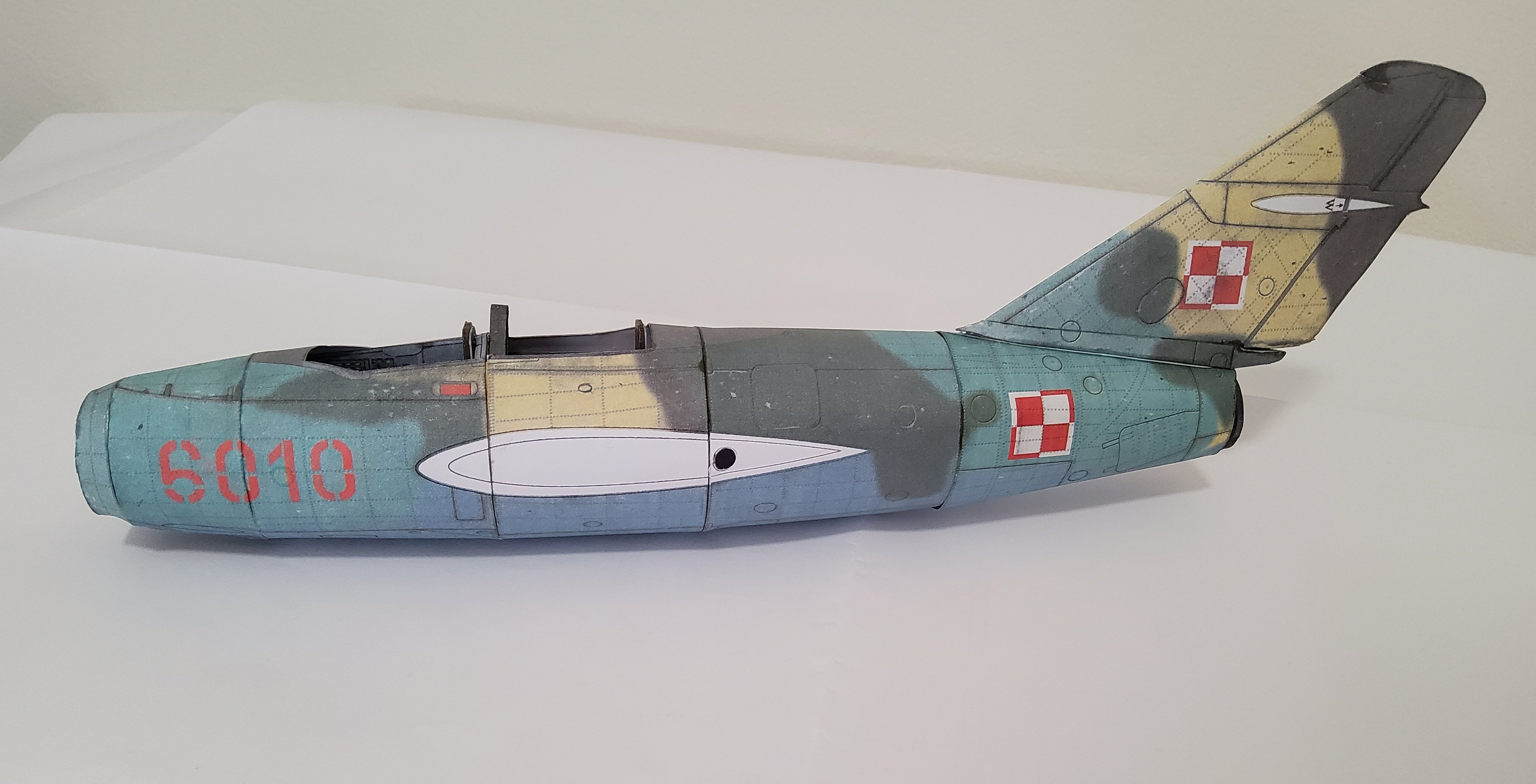
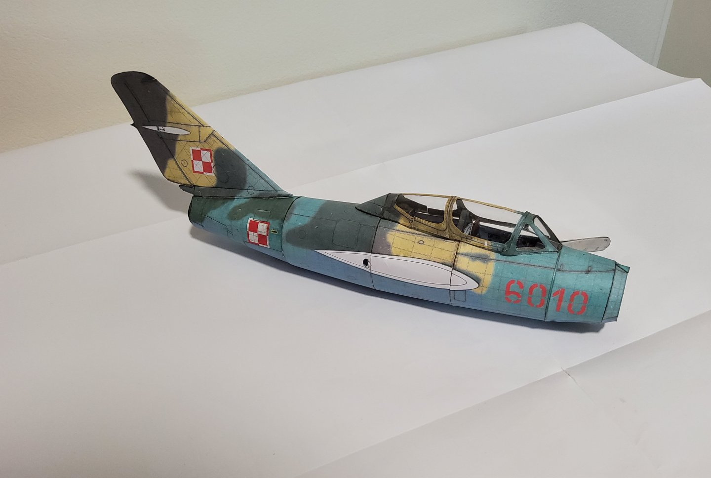
The second wing was completed without much trouble. The two wings were mated to the fuselage, though this was not quite so simple. As I mentioned before, I'd squeezed the fuselage somewhat so the place where the wings had to go was not as even as it should have been. A little surgery at the wing roots proved to be sufficient. The wing fillets then covered the slight gaps that remained. A dowel joiner assisted this. The tailplane was quite easy and was glued in place without any trouble. The two halves were joined with a laser-cut spar. Next, the undercarriage - should be fun 😁. Cheers
-
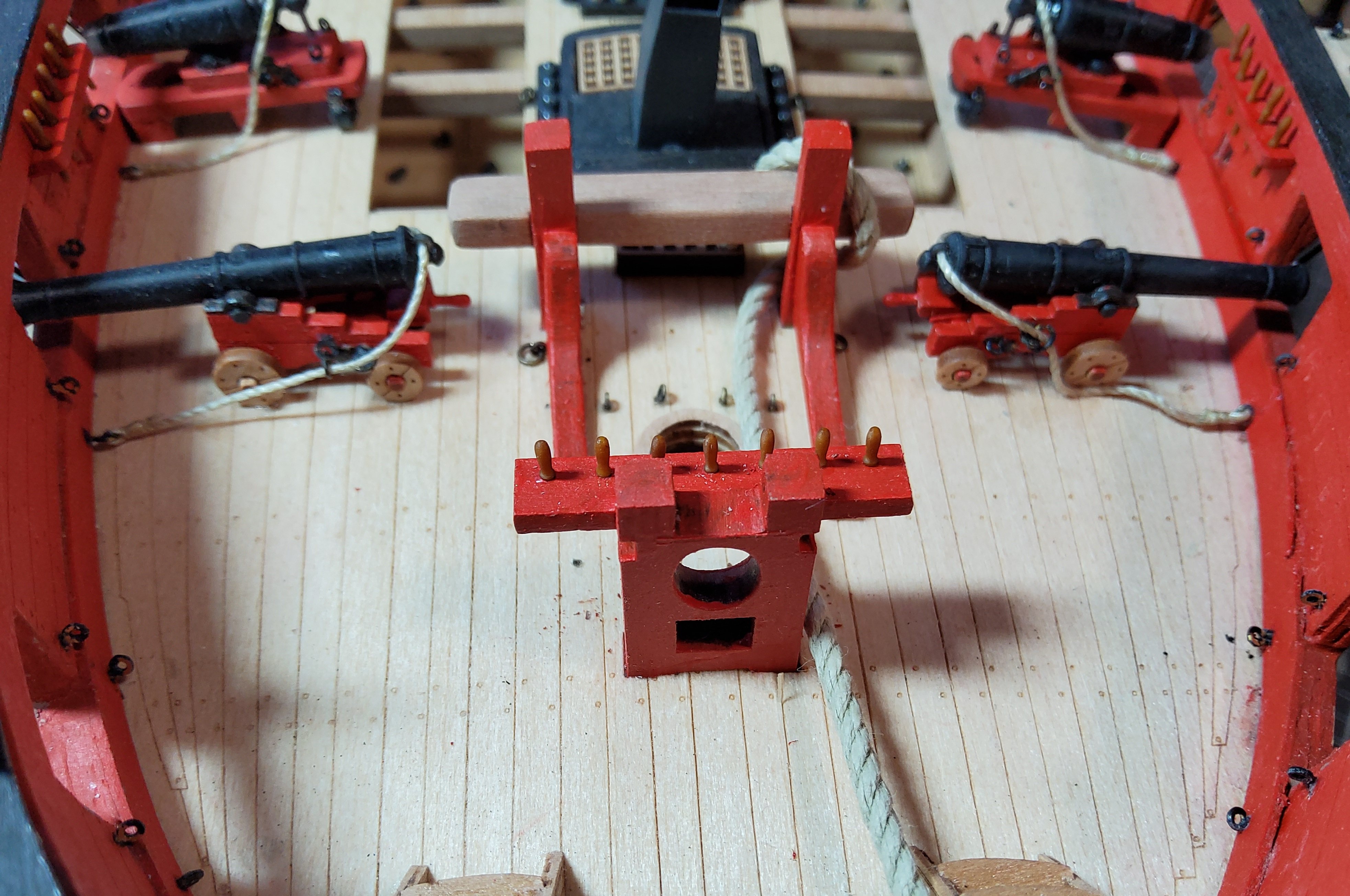
I'm hijacking Maurice's thread here a little. I did a trial fit of the anchors on my Harpy but ran the cable around the bitts and then down the hole in the foremost grating as the instructions suggest. However, I can see a potential problem with my method and and also with Maurice's. If I've read the rigging plans correctly, there are four rigging lines tied around each end of the horizontal beam of the bitts. Some interference would almost certainly occur between the rigging and the anchor cable if the latter is also wrapped around the bitts. Maybe the rigging lines have to be moved. A bit of a puzzle. Cheers


- 332 replies
-
- 3
-
-
- Harpy
- Vanguard Models
- (and 1 more)
-
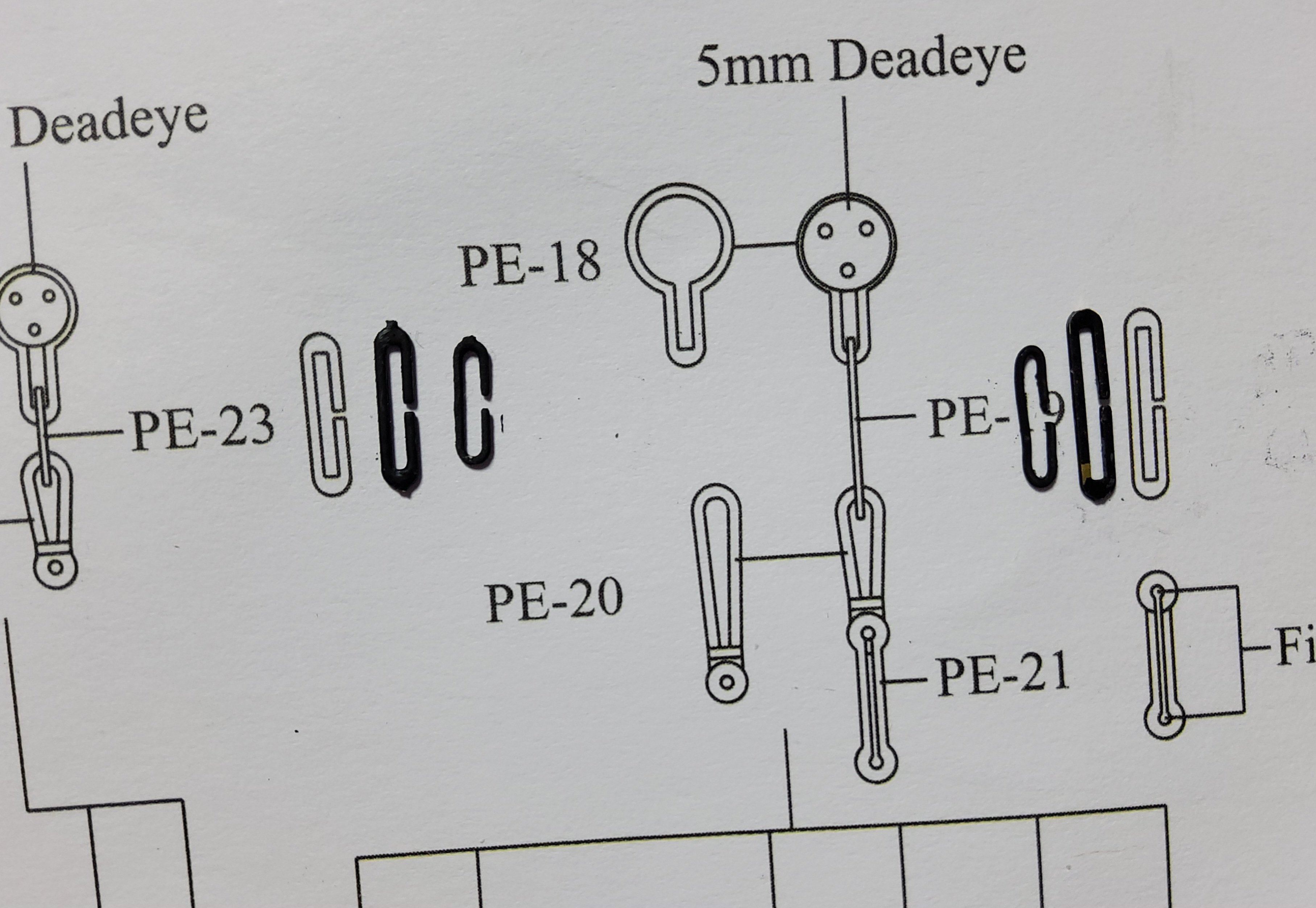
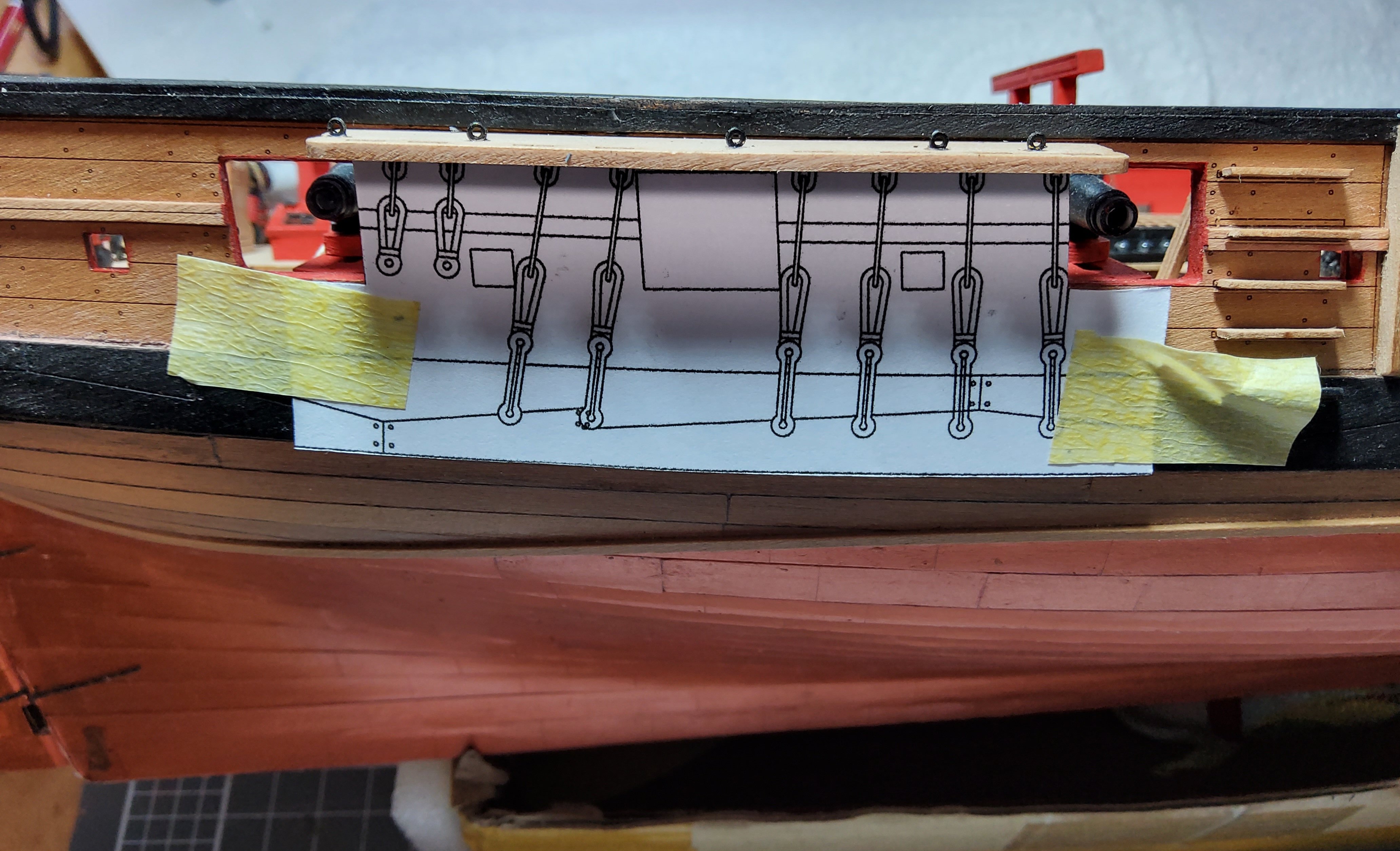
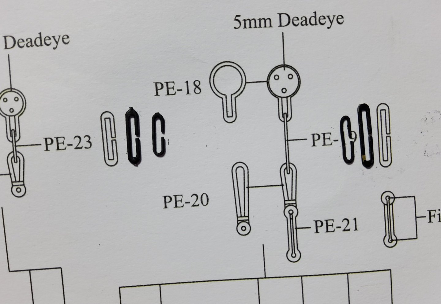
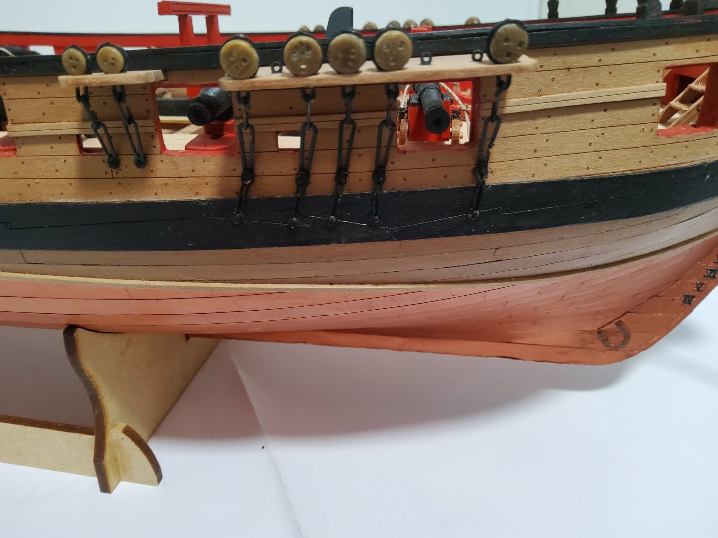
Another brief update. The chain plates were the next to be done. As Blue Ensign pointed out in his build log, the supplied PE parts are slightly too long when compared to the plan diagram and to their locations on the hull. Shorter links were made to replace the PE parts 19 and 23, and these are shown in the photo next to the originals. To get the correct angle of the chain plates, I copied that part of the plan and taped it in position on the side of the hull. A sharp pin was then pushed through the upper mounting hole of the preventer plate to mark its position on the hull. The deadeyes and their PE strops were assembled and placed in the channels. The chainplates were attached to the strops below the channels and nailed in position, firstly through the upper mounting hole of the preventer plate using the locating marks as mentioned above, then the second, lower nail was fixed through the preventer plate. The angle of the latter was eyeballed to keep it in line. The tiller was rigged. Seven turns of the rope were wound around the drum of the wheel, then fed through various blocks, finally being terminated at an eyebolt at the side. The rudder chains were attached. Finally, the anchors were assembled and rigged ready for installation. The ring to which the anchor rope is attached was wrapped in cord to represent the puddening (great word😄). Only three anchors though instead of four. As I have not worked with resin-printed parts before, I was not aware as to their brittleness, and broke one. That's it for now, cheers.


-
Your log helped a lot. I gave up on the instructions, used the diagrams though, but mostly relied on your description and photos. Thanks Chris.
-
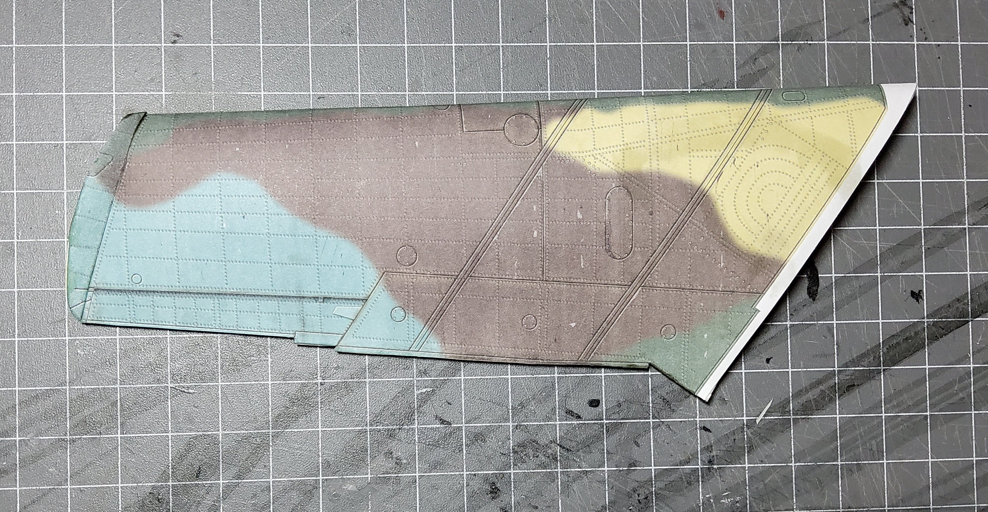
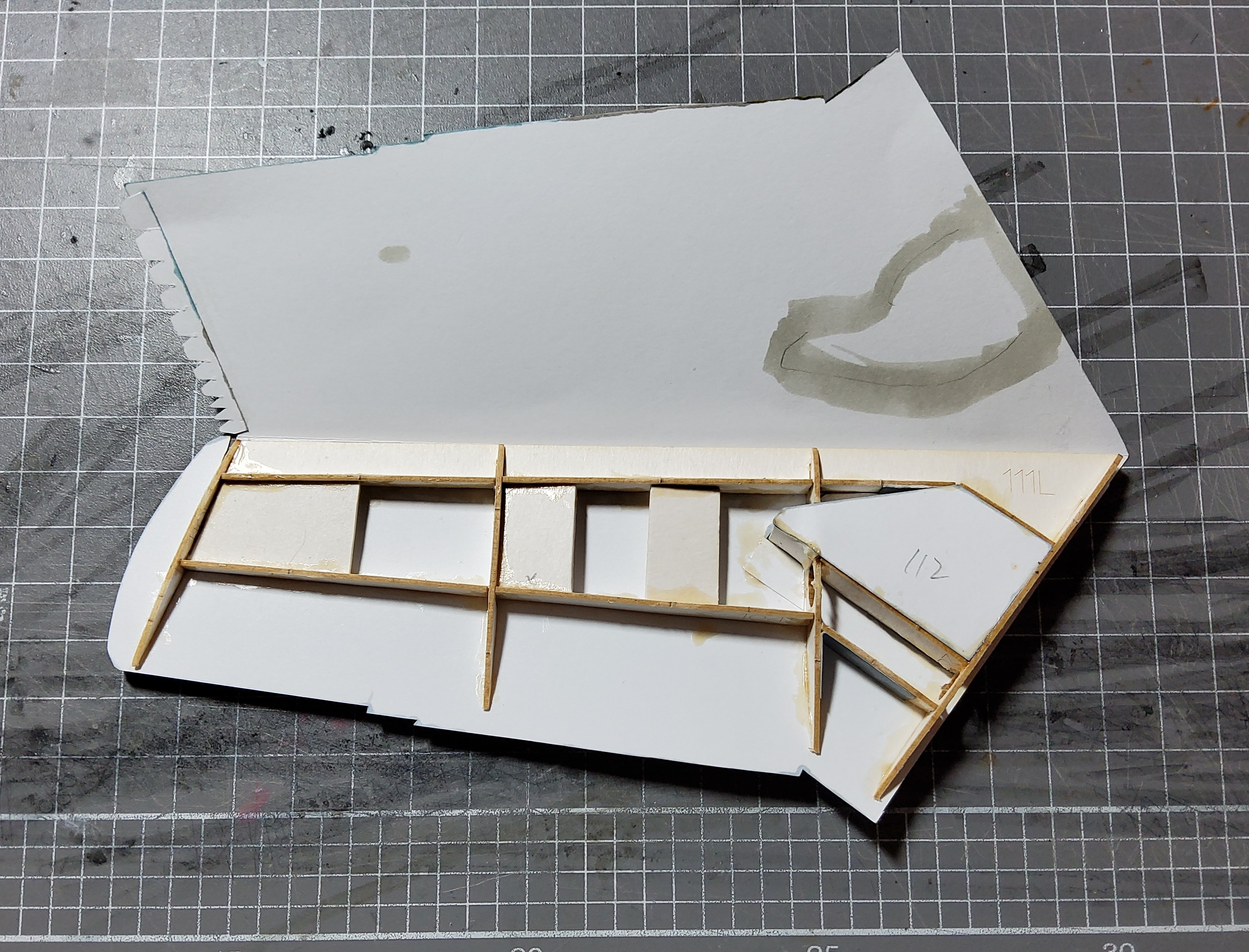
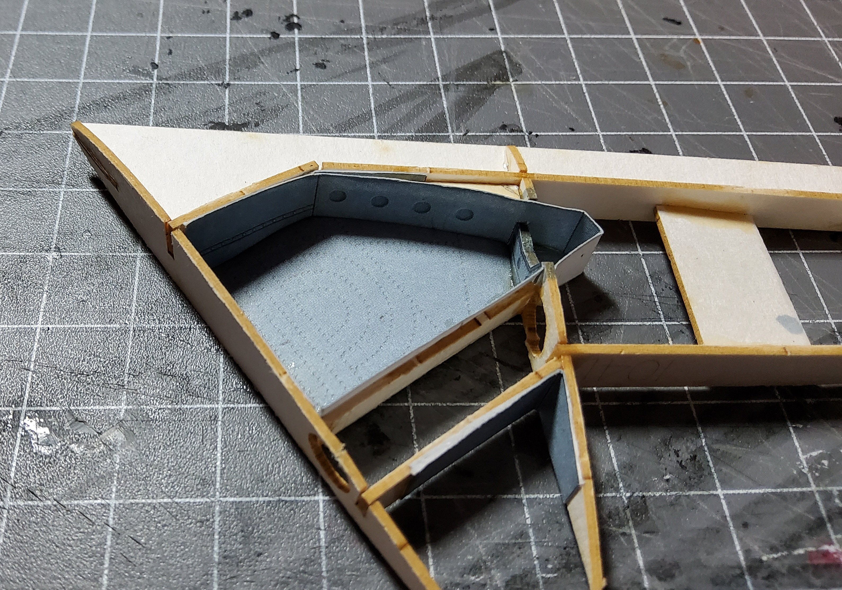
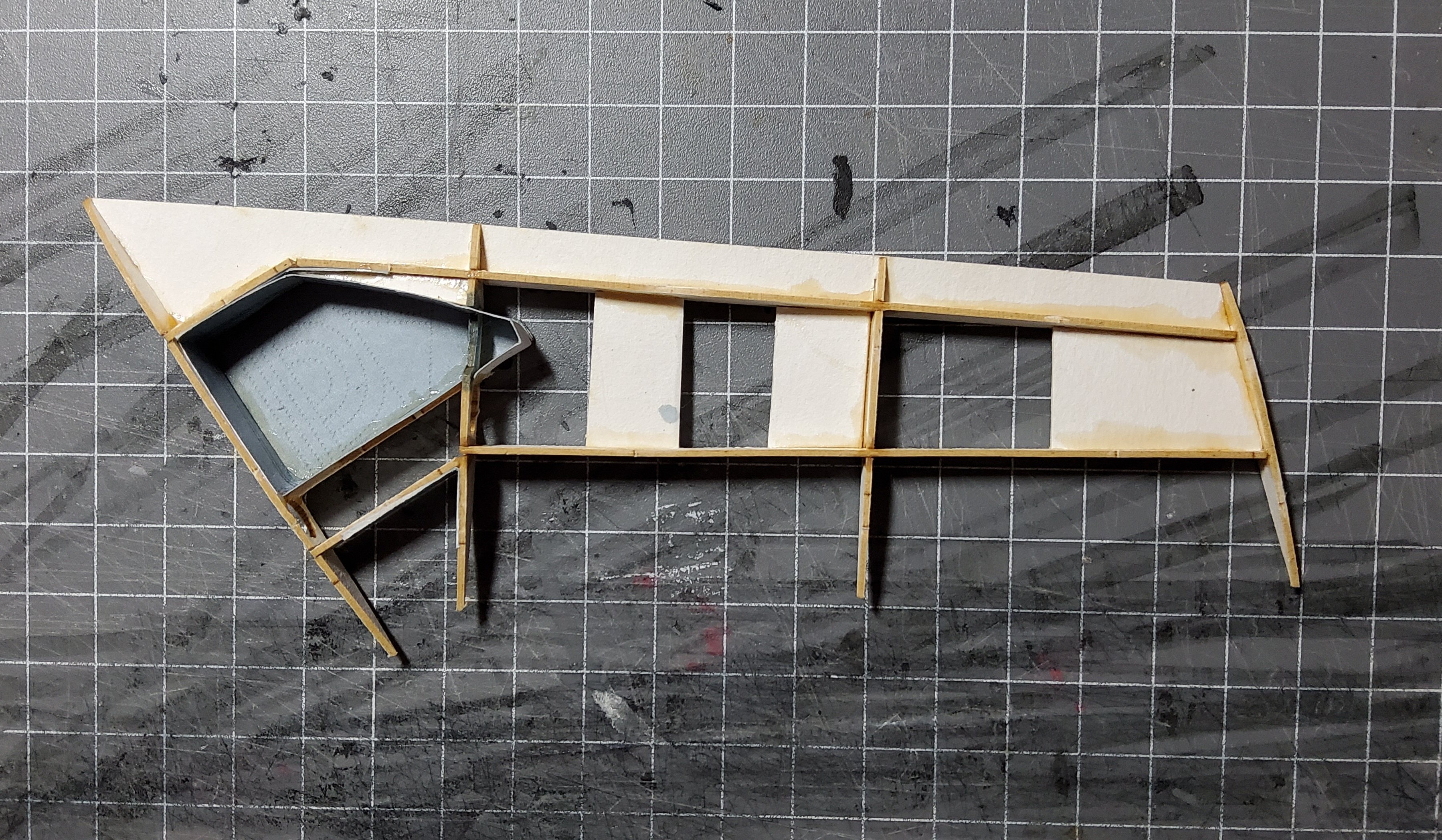
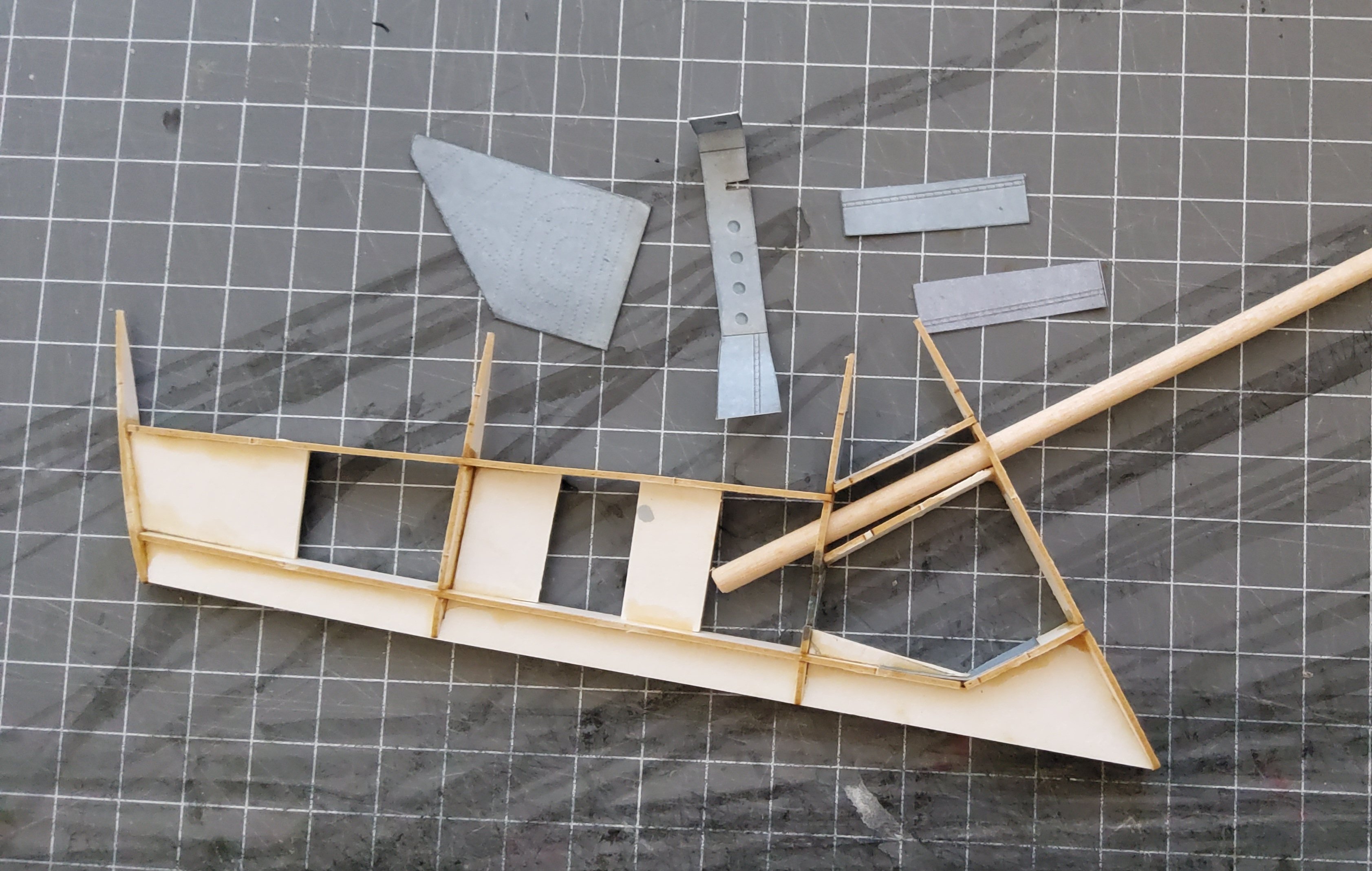
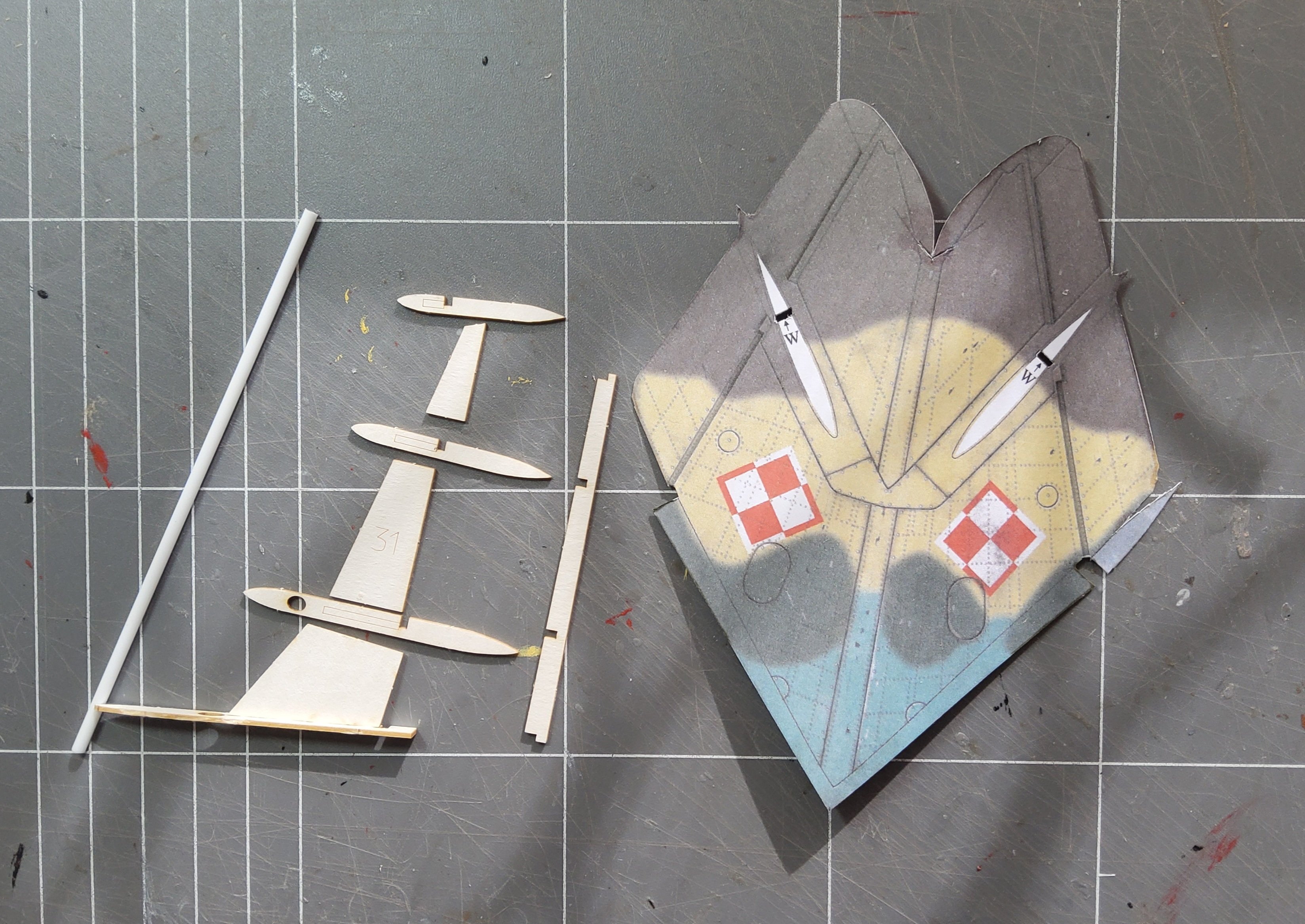
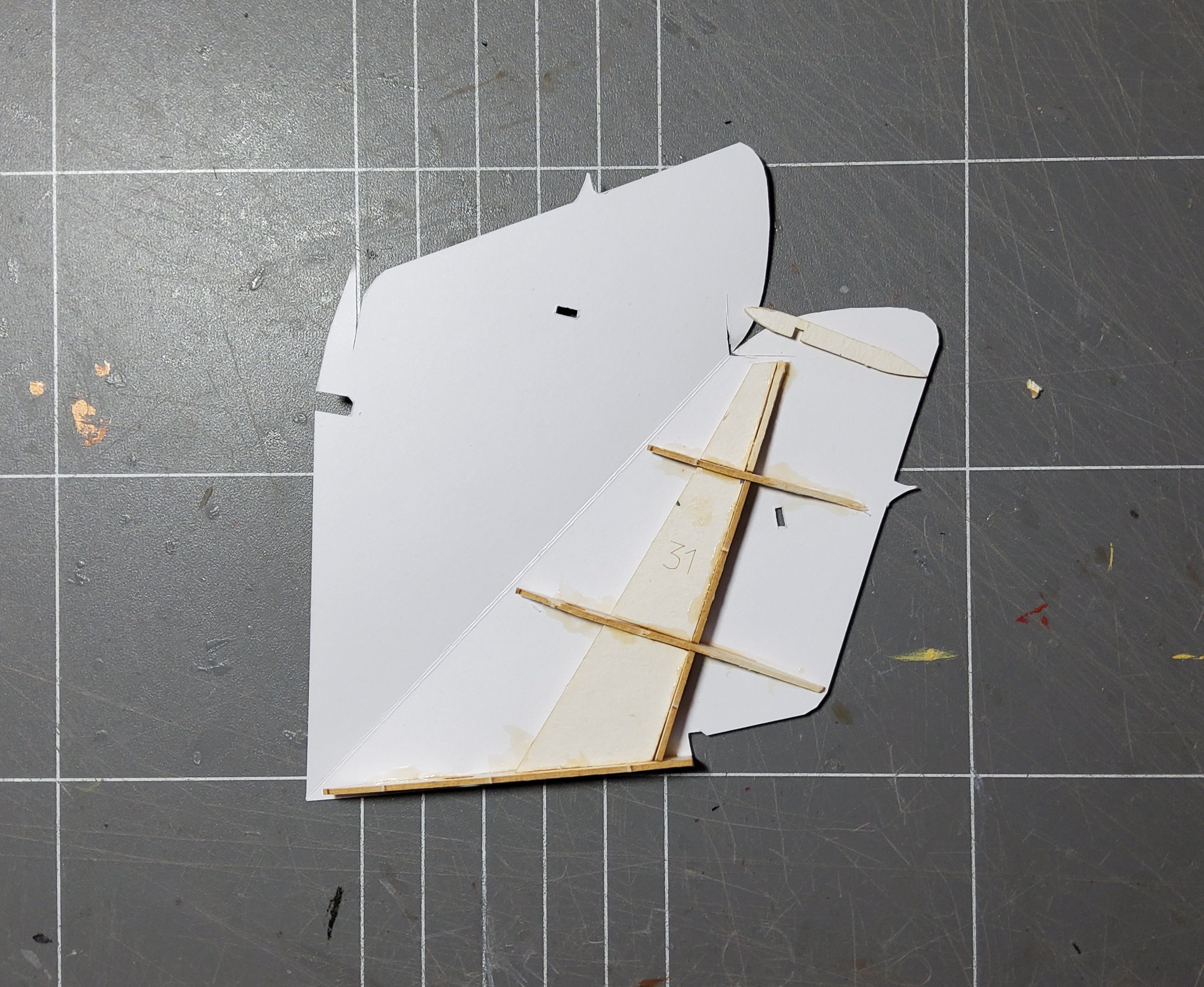
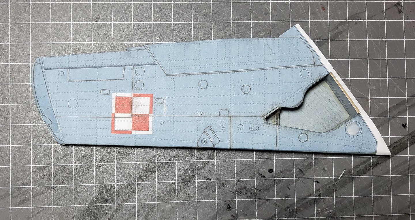
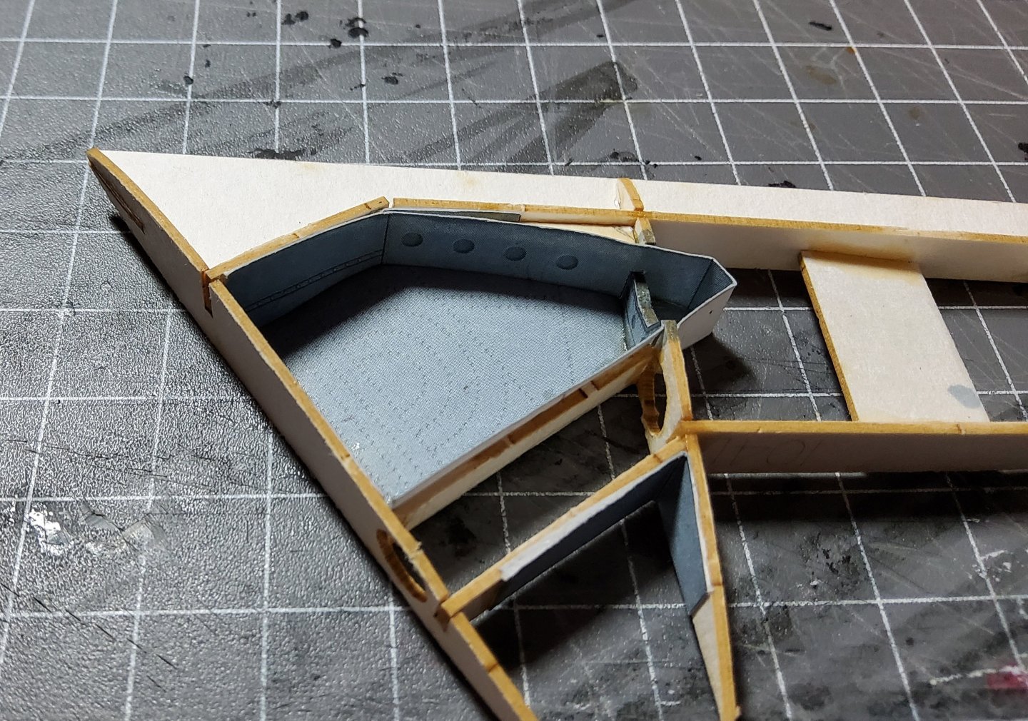
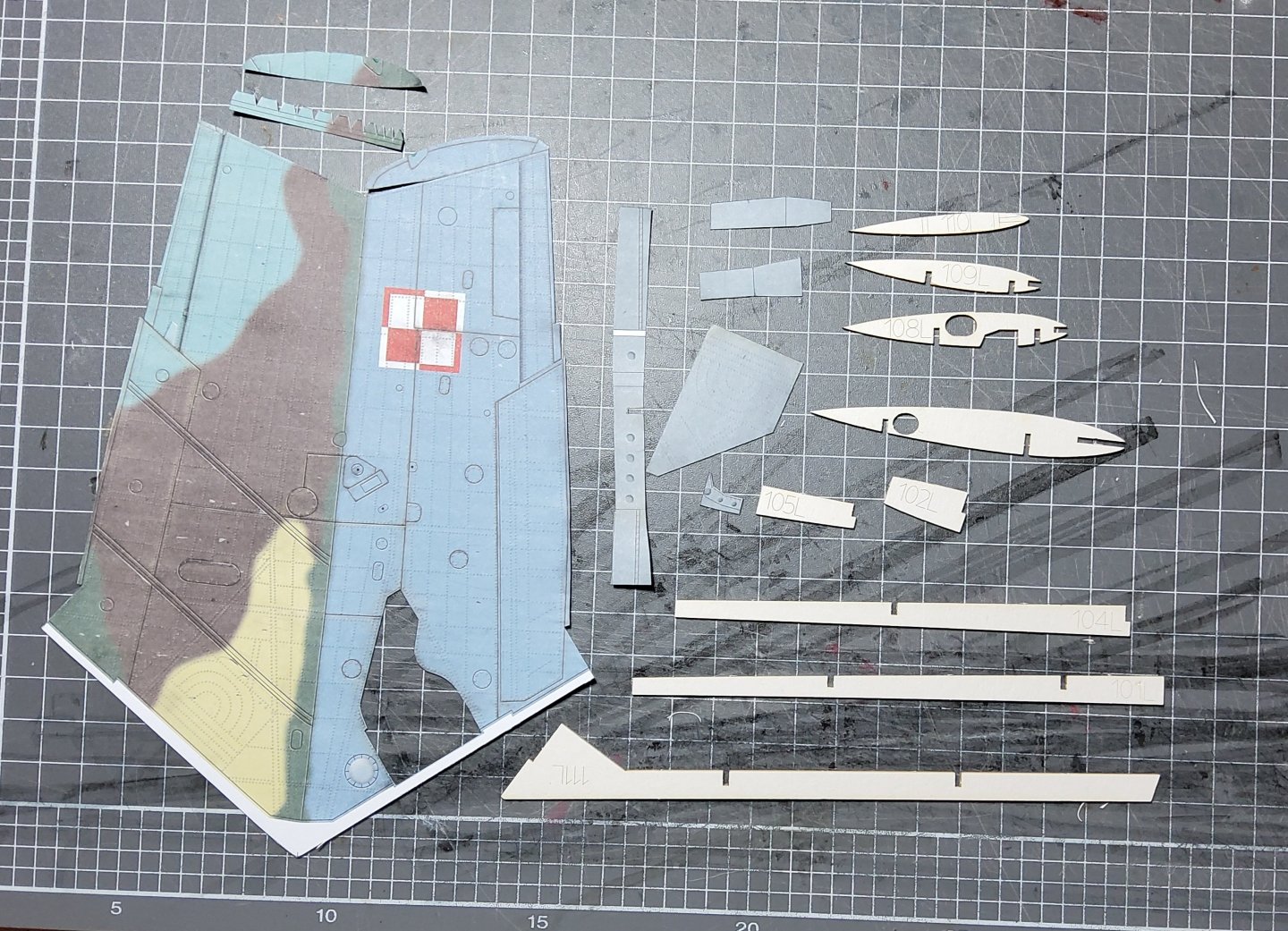
Time to tackle the wings. These have an internal structure made from either laser-cut material (which I have) or diy laminated card, and a one-piece skin. There are also two options, full undercarriage with wheel wells or not. I've gone with the full undercarriage. The photo shows the parts, with the cutout for the wheel well visible. There's no strength in the laser-cut material, and the assembled frame felt weaker than any I've made since my days with sticks-and-tissue planes way back. So I added some bracing. The wing joiner rod is also shown in the next photo, as are several pieces that will line the interior of the wheel well. The completed wheel well. This was not easy, and the fit was not great. But it was finished. The next photo shows the frame glued to the lower part of the wing skin. Getting this in place accurately was a test of my patience. The power of certain words did help 😁 😁. The well had to be aligned with the cutout in the skin underside as well as lining up with the trailing and leading edges. Can't use clamps to assist as these just collapse the card. The completed wing (the other one should be easier, but no guarantee). Cheers.


- 28 replies
-
- 10
-
-
@ccoyle Hi Chris, I'm about to do the wings and I notice that you added joiner strips to the trailing edge. Hard to tell from your photo but it looks like you used strips of laser fret. I have a very vague memory of you describing similar strips in one of your older build logs, but made from folded card. Which did you use here? Thanks.
-
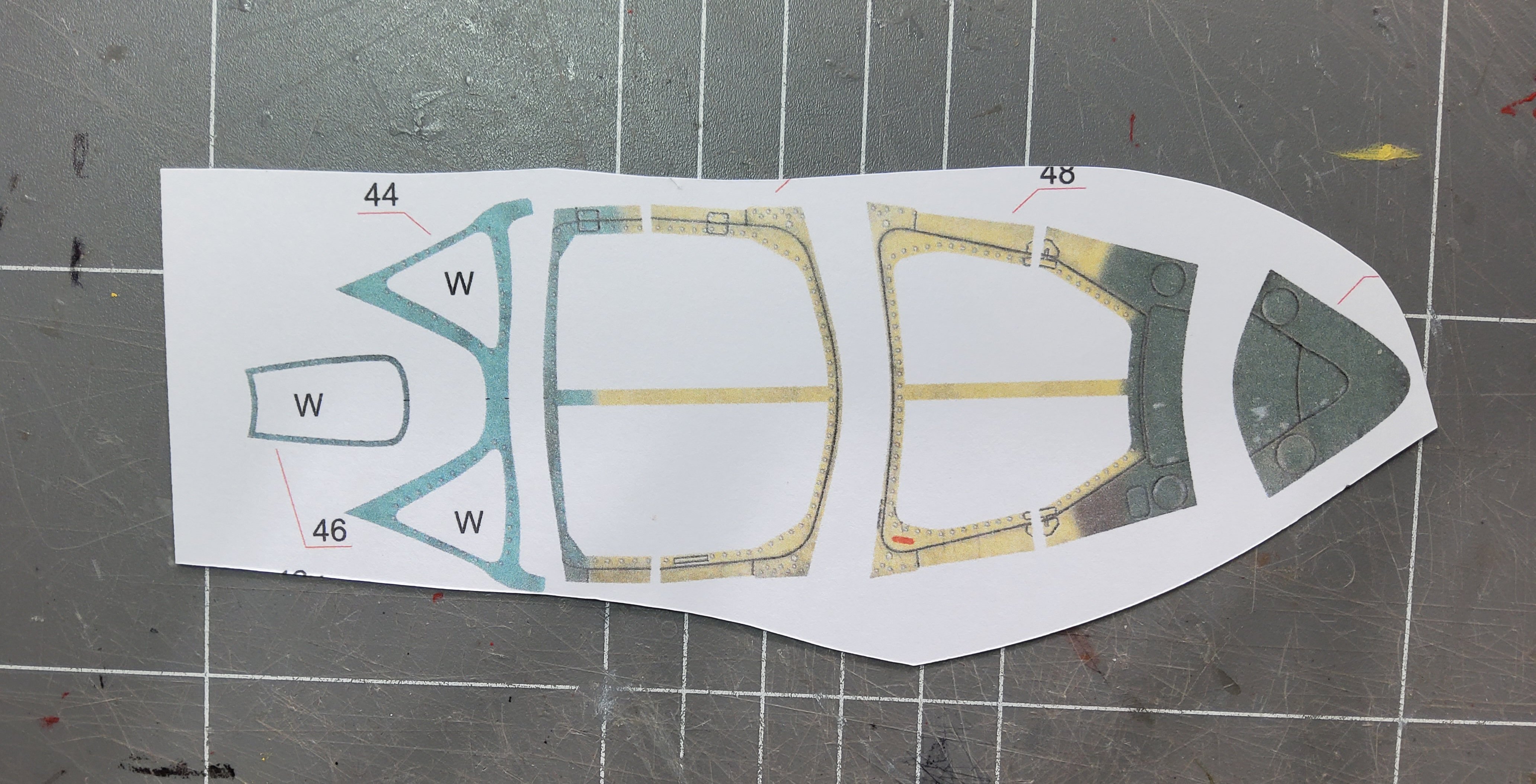
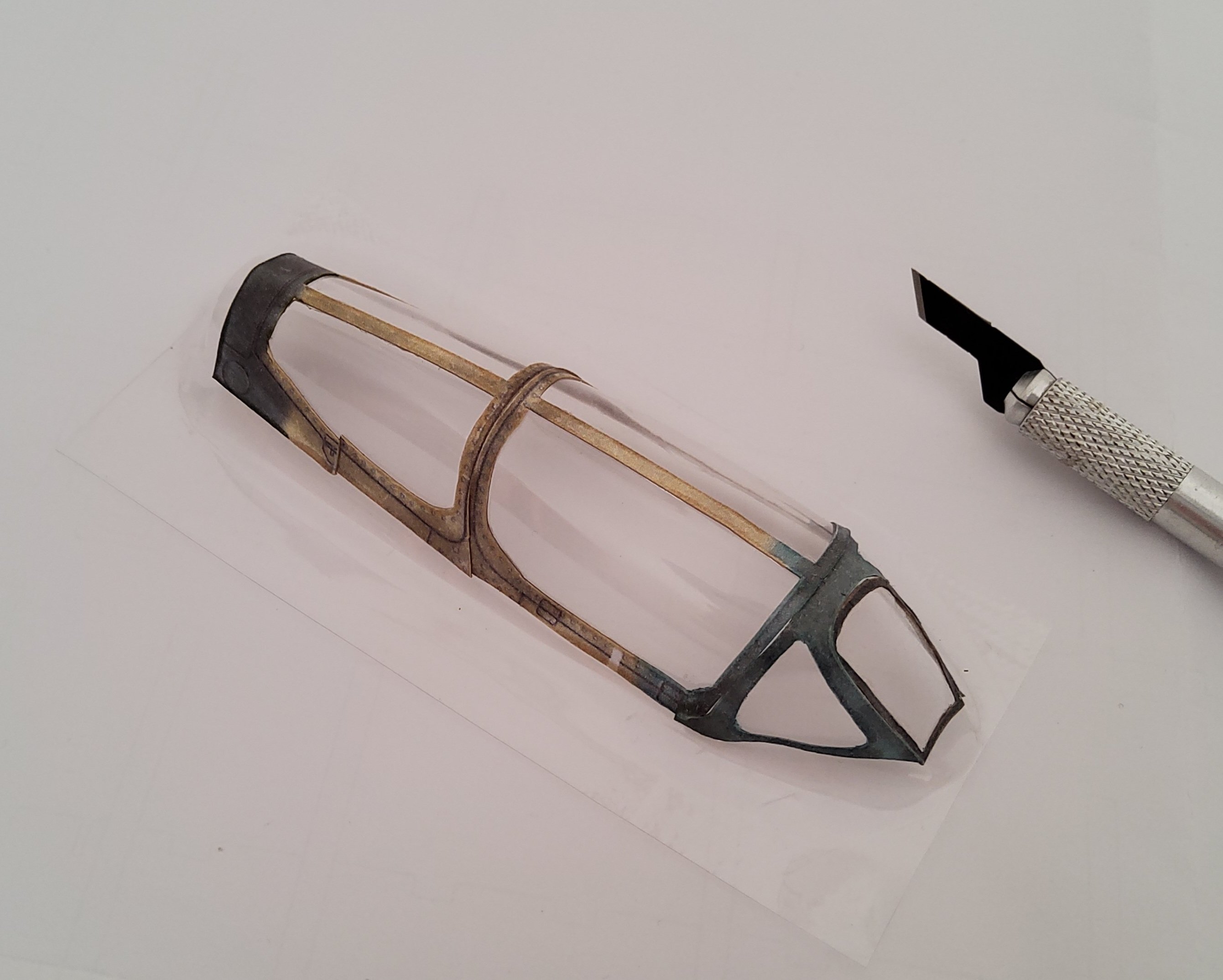
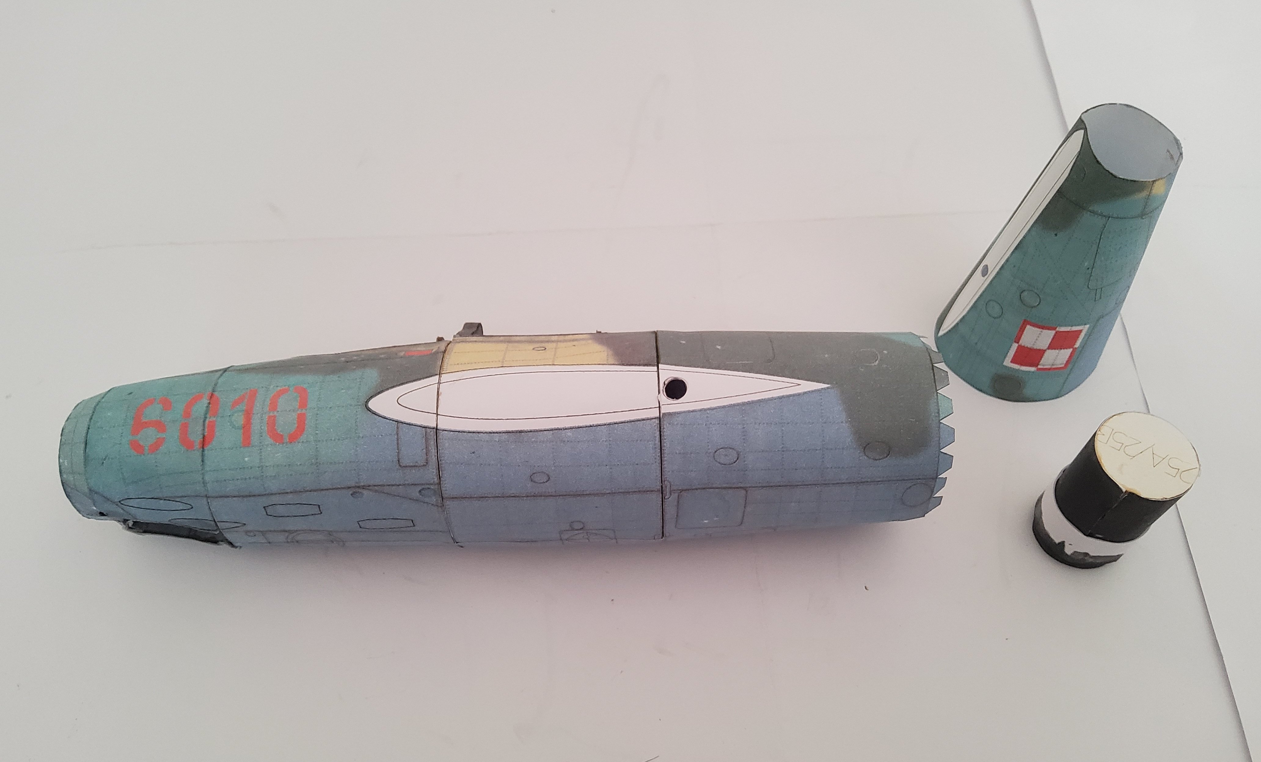
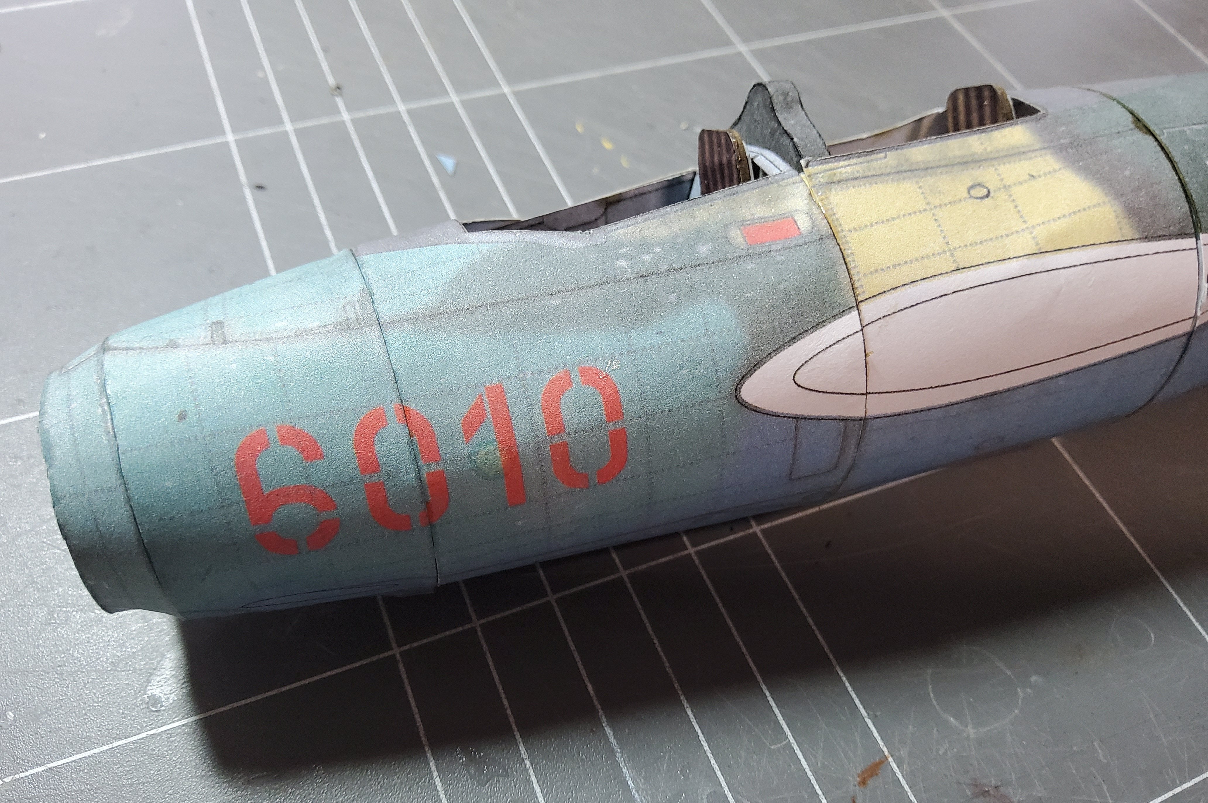
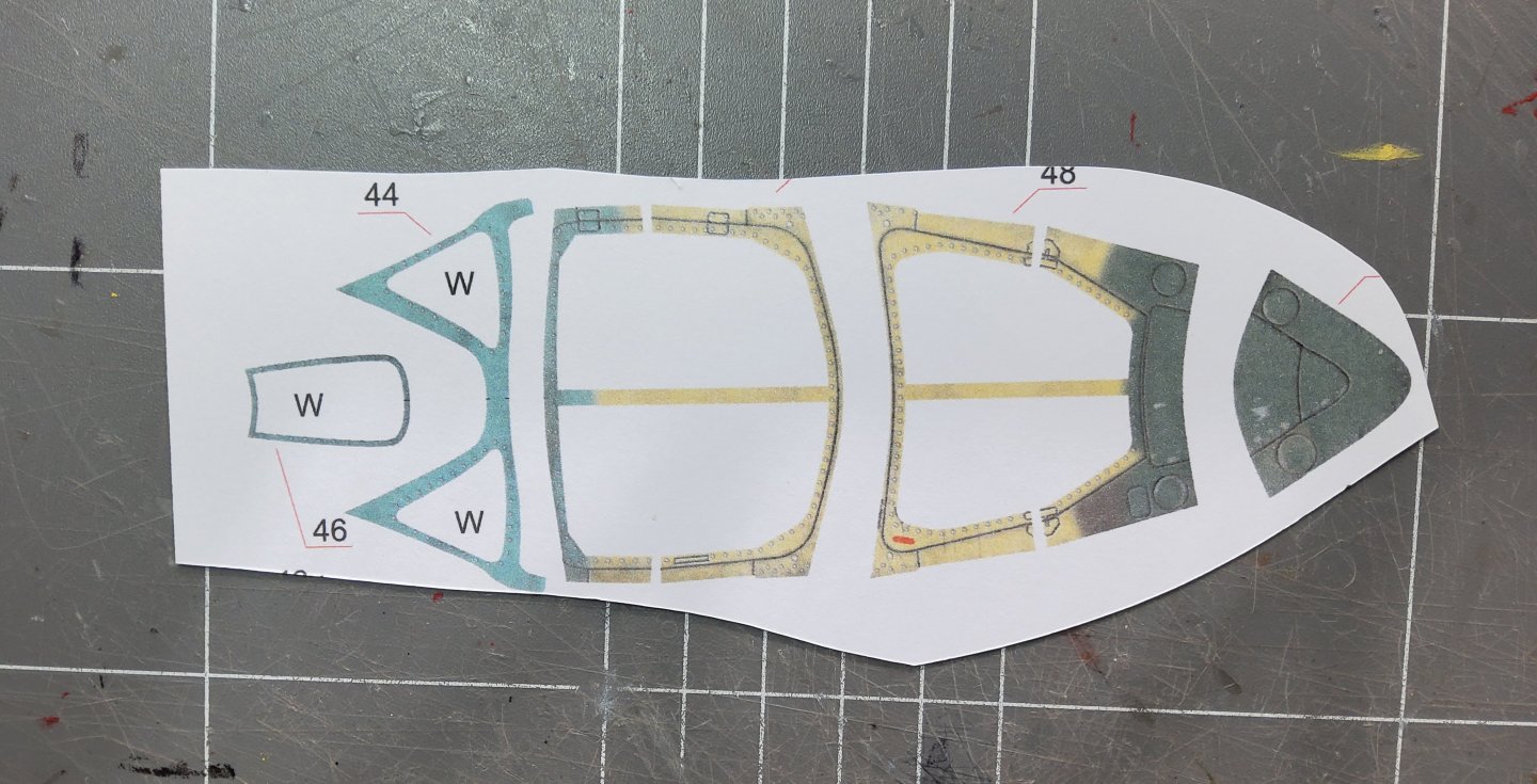
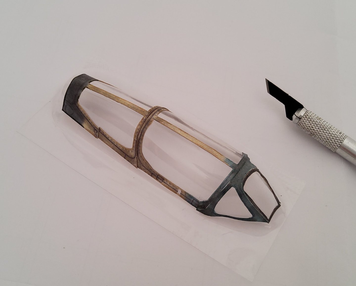
Next up was the canopy. I ordered a clear vac-formed canopy when I bought the kit. I would not have liked to assemble a canopy from printed card. The first photo shows the parts of the frame, yet to be cutout. In the second, the frame has been glued, piece-by-piece, to the canopy. Fairly successful but not totally so. The third photo shows the fuselage with the canopy in place (and yes Chris, I remembered the gunsight 😁). It is noticeable in the photo, and even more so when looking at the plane in your hand, that the canopy does not sit flush with the fuselage. This is because card models are susceptible to being crushed if gripped too hard - and that is what I did with the MiG. The fuselage is slightly crushed in the cockpit area. That's it for now. Cheers.
-
Thanks for the comments.
-
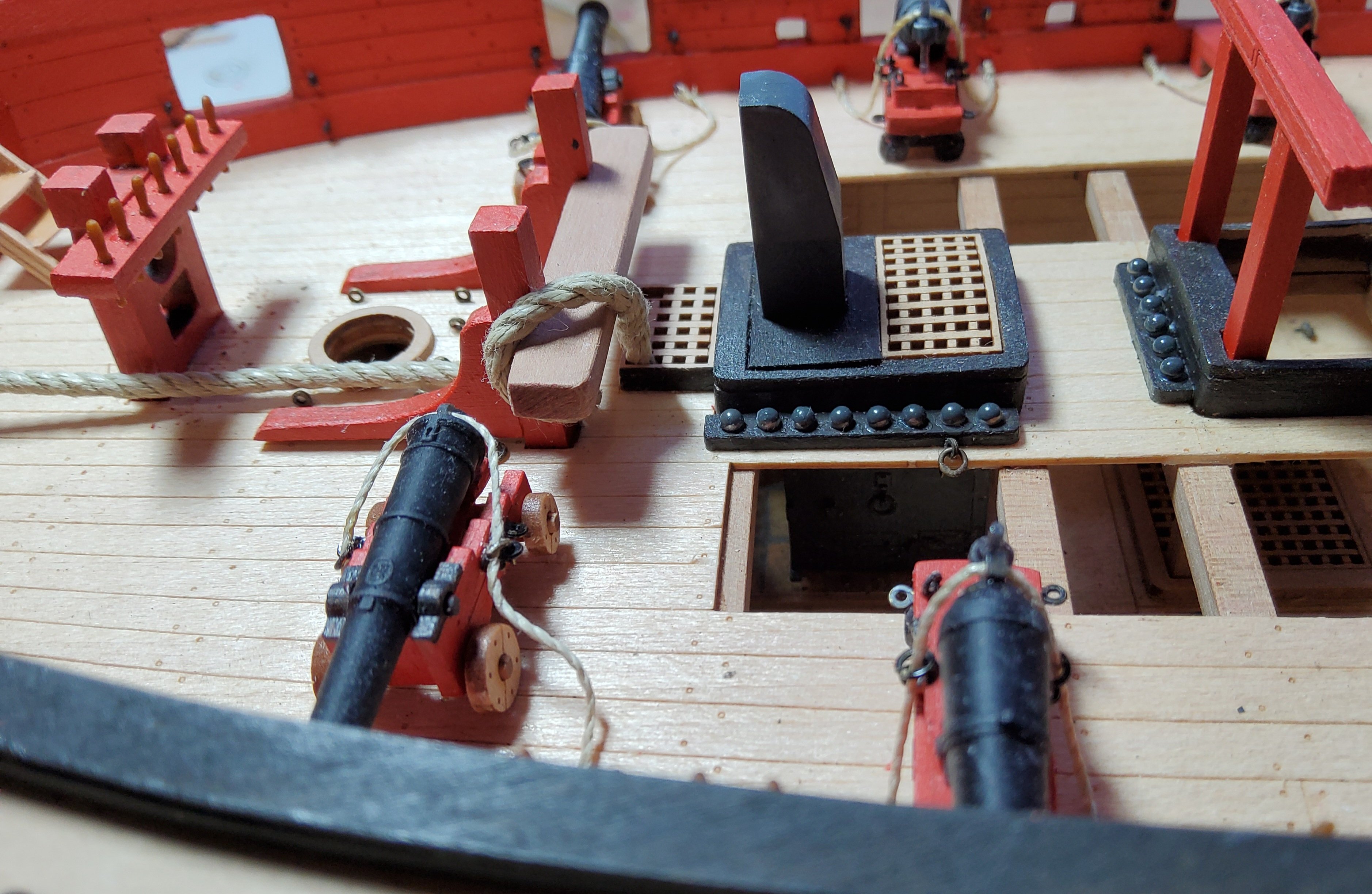
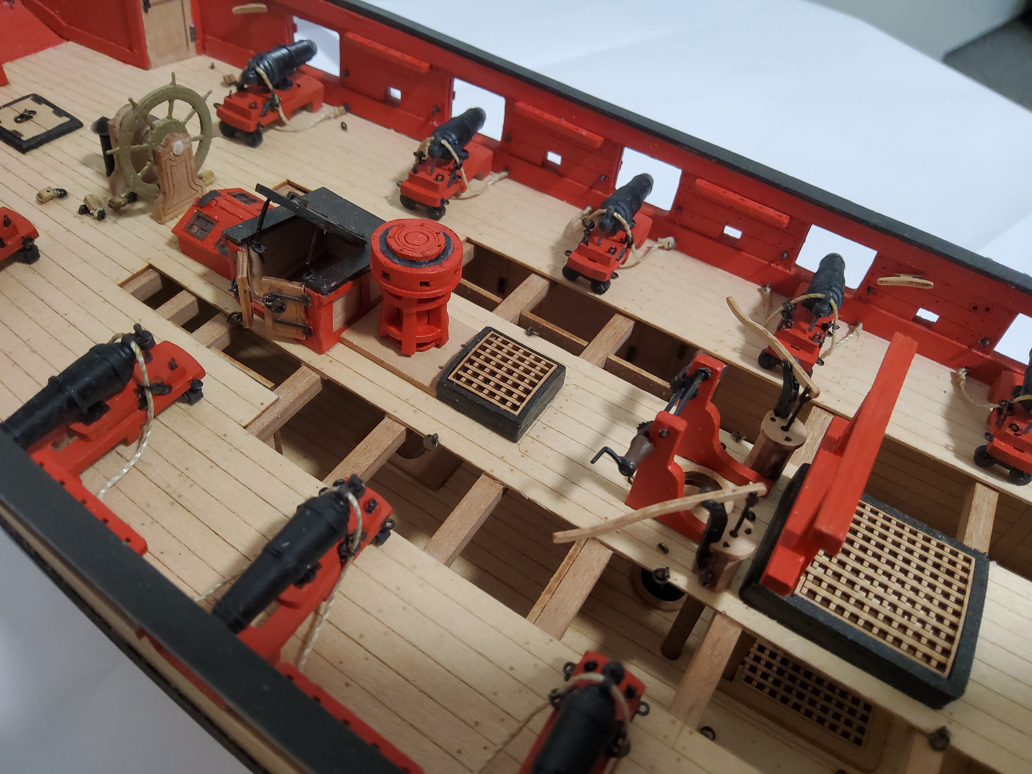
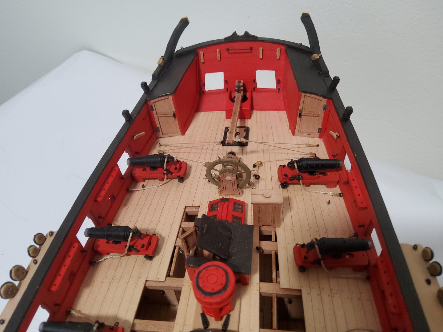
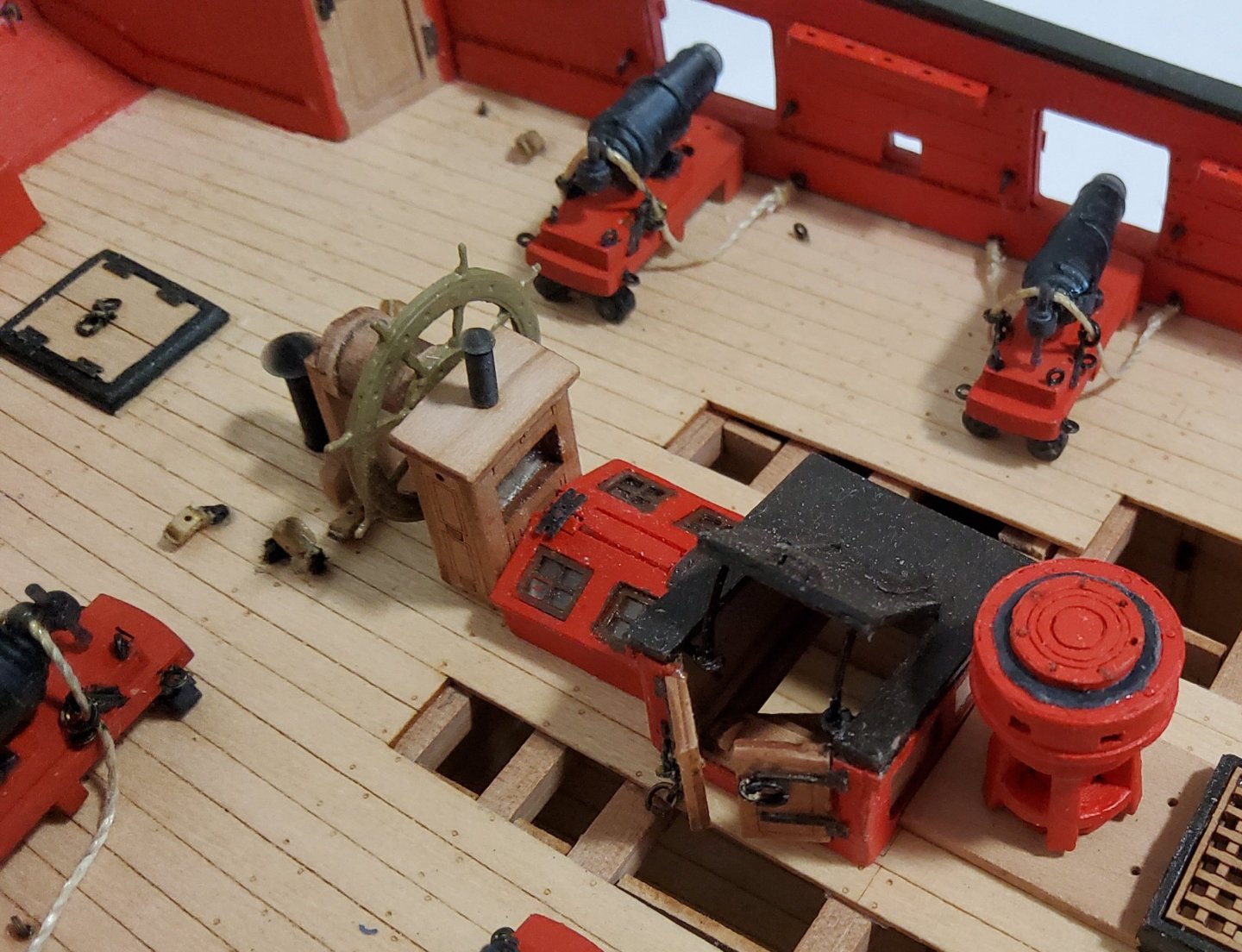
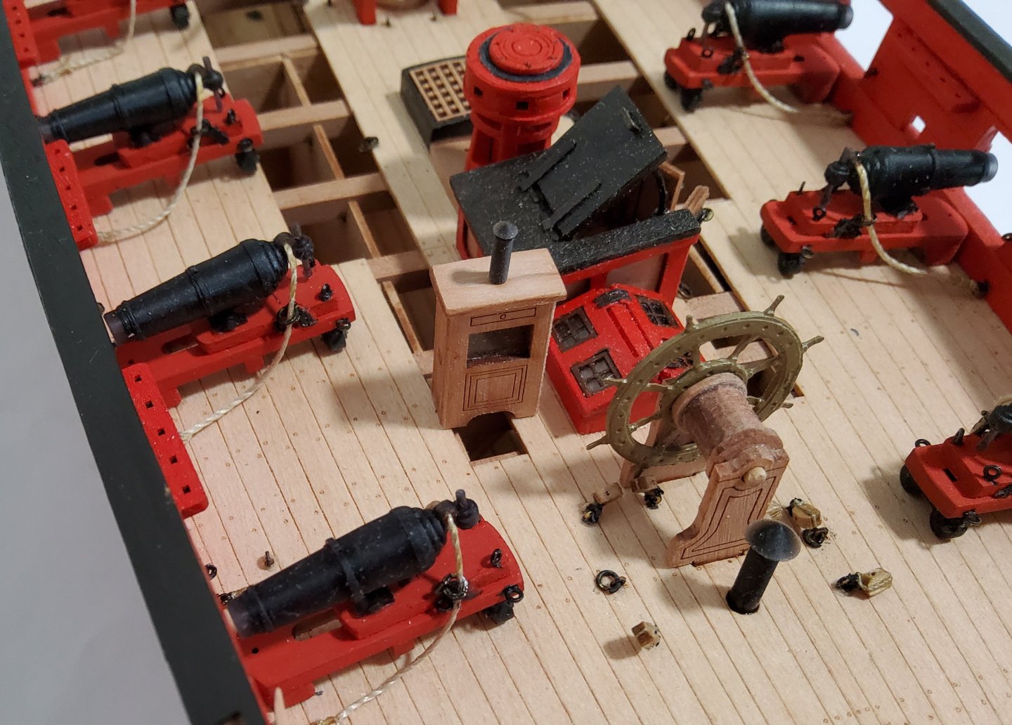
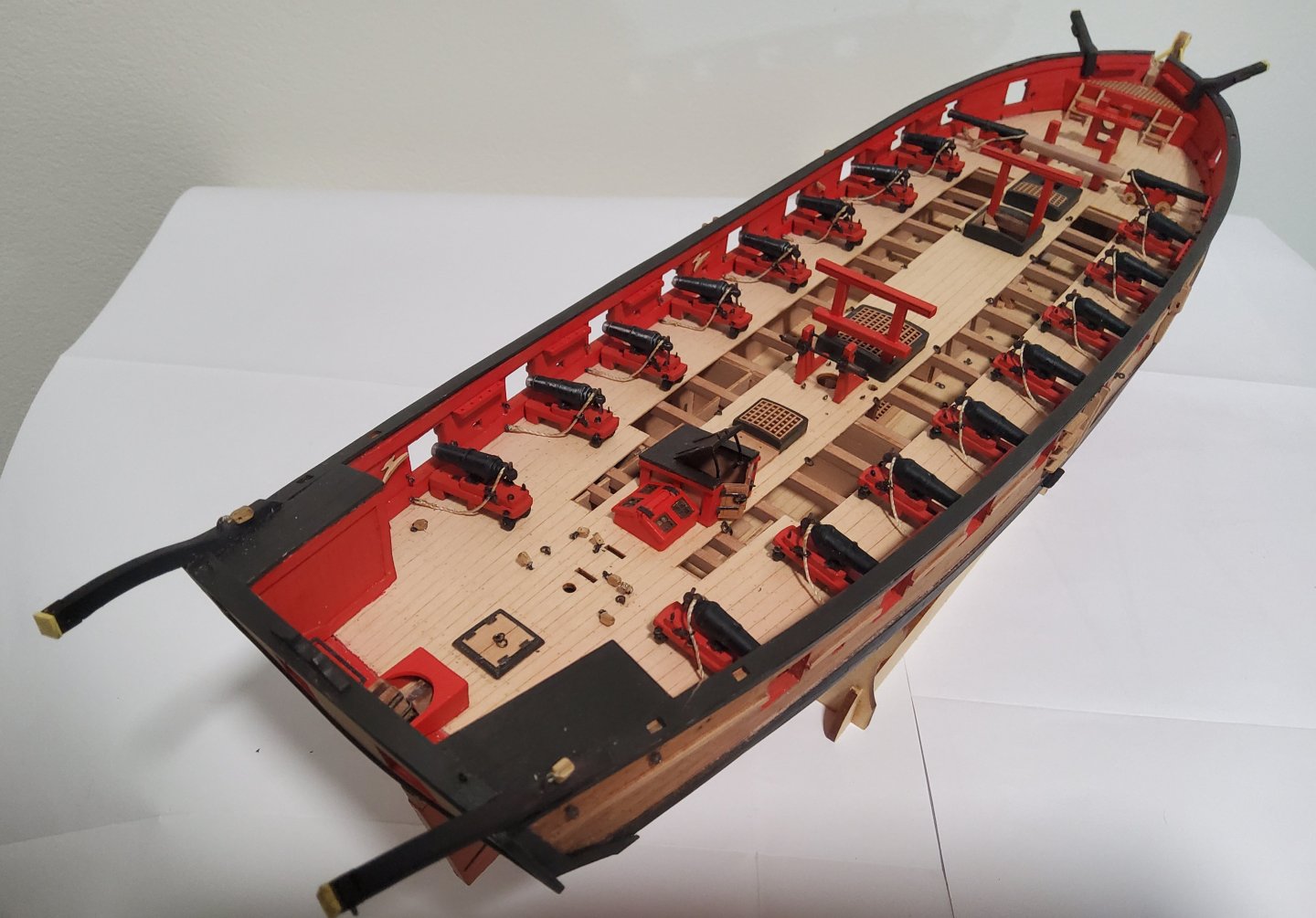
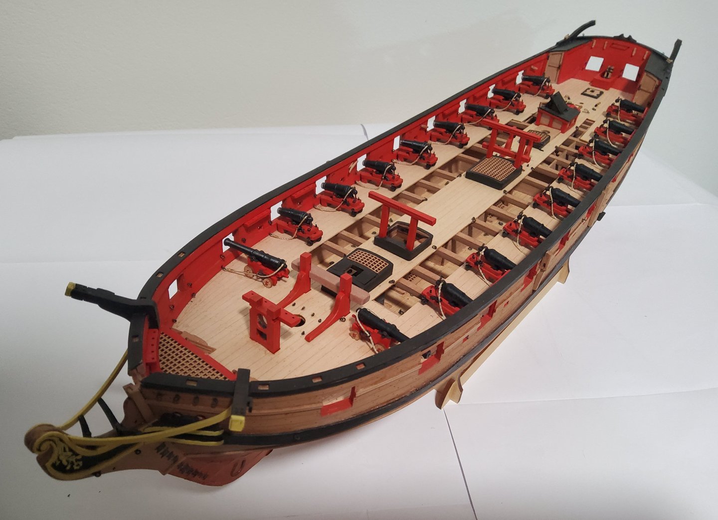
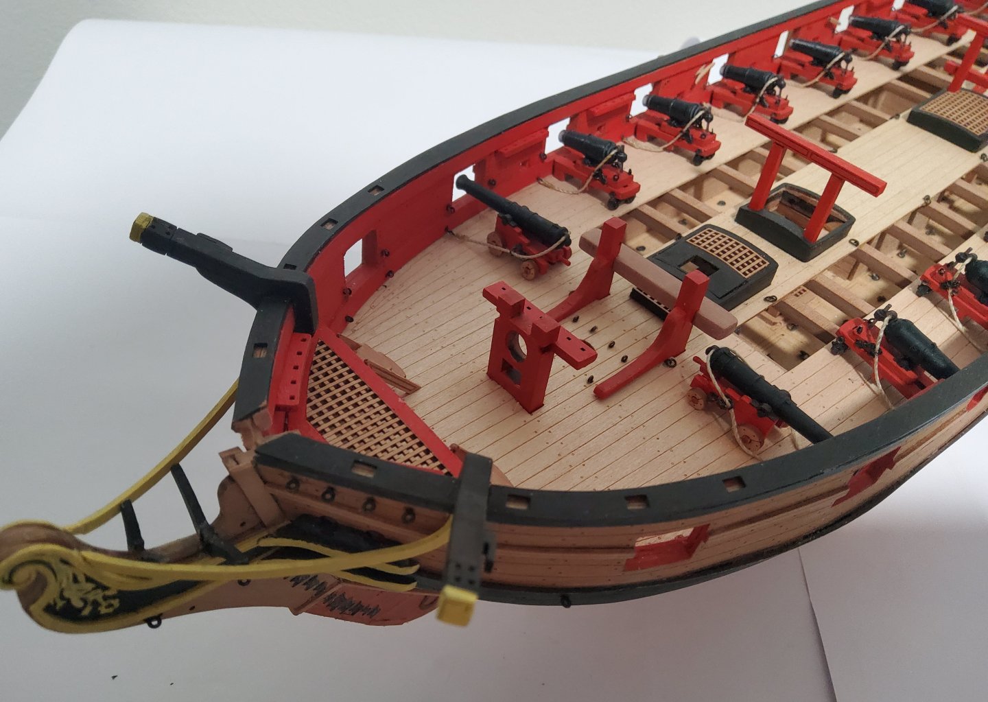
A brief update, not much to report. The following were added to the hull - boomkins, timber heads, shot garlands and the shot, and the channels. As I suggested in my previous post, I decided to fix the binnacle in front of the wheel and offset to port. If this is where the binnacle was really positioned, then my guess is that it was lashed to the deck and removed prior to battle (and could be moved side-to-side as required). Cheers


-
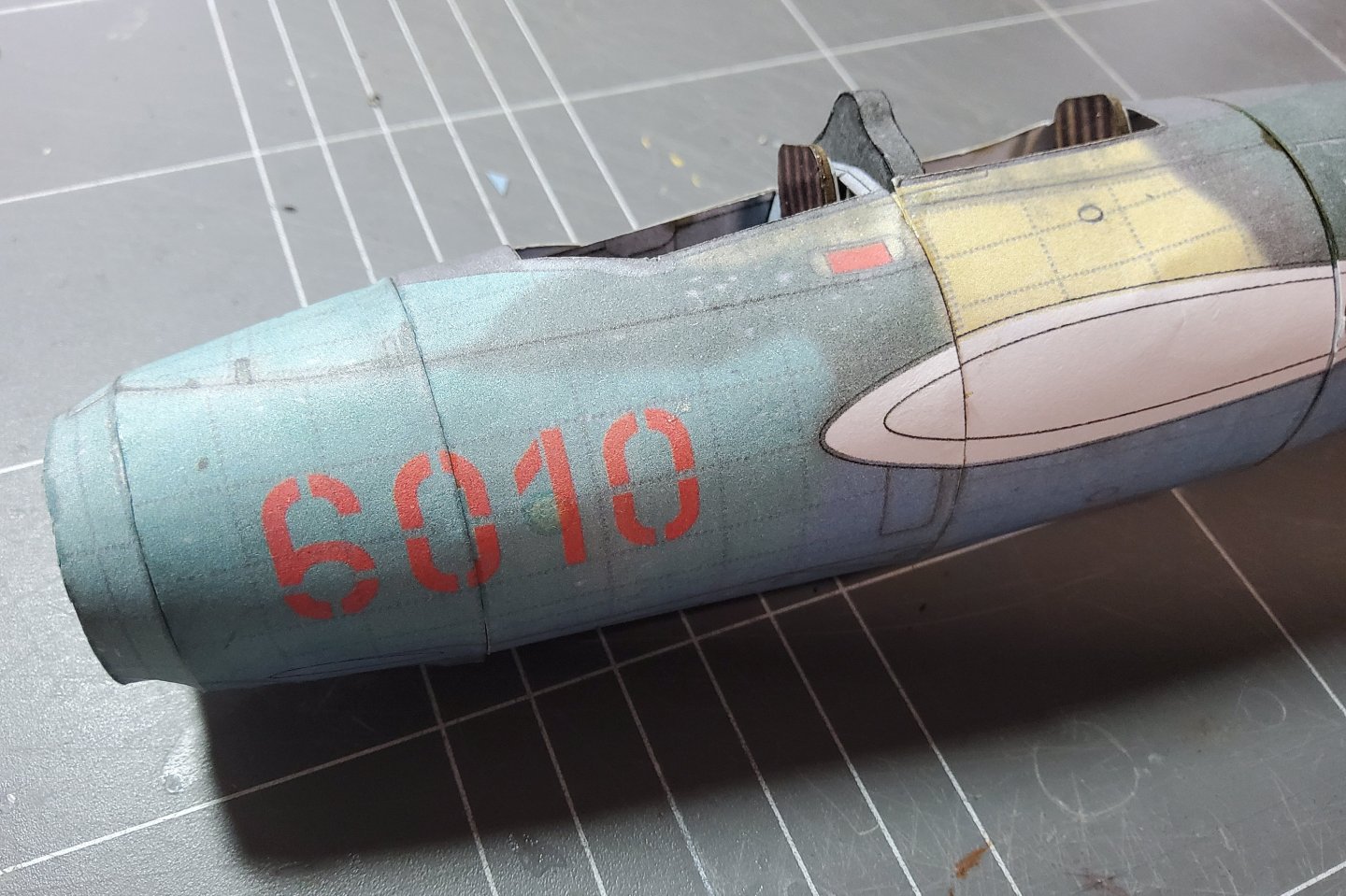
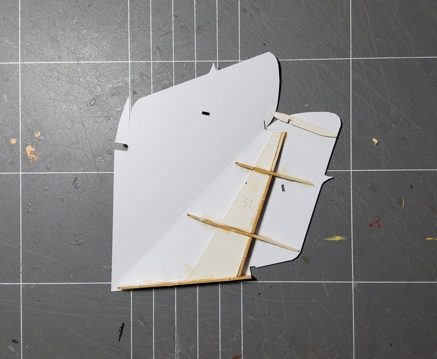
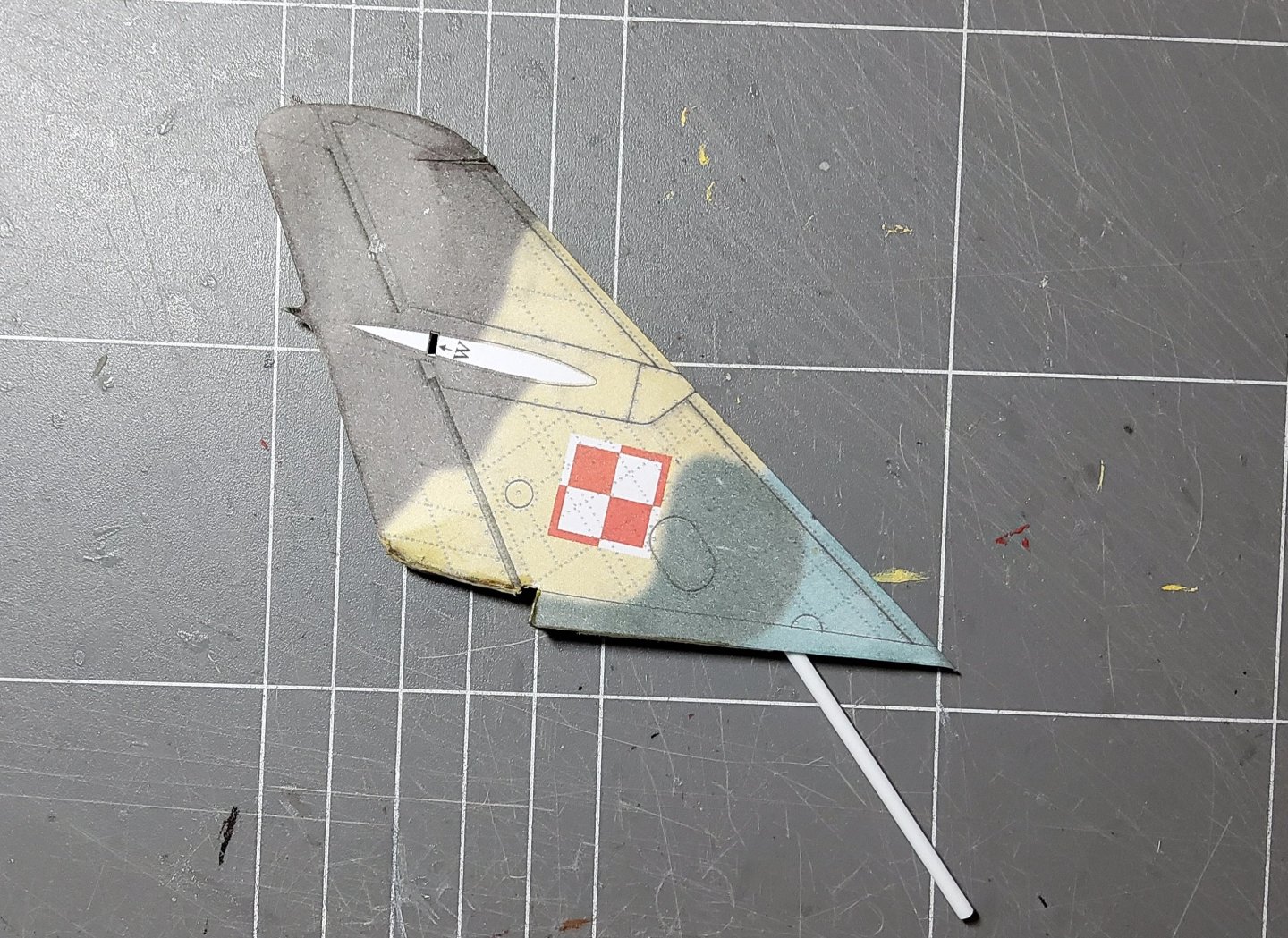
OK, back to the MiG. The forward section of the fuselage was built again and the rear-most section and tailpipe added. Photos are a little lacking I'm afraid. Next was the vertical stabilizer. The photo shows the parts - the skin, the laser-cut framing and a length of styrene rod that acts as a support/brace for it. The rod extends down into the fuselage and into one of the bulkheads. As Chris said in his log, the dart (to be cut out) at the top of the stabilizer appears to be unnecessary, but I did it anyway. However, a dry fit made me think that the topmost former was also unnecessary as omitting it would make closing the seam at the top easier. So I left it out but tapered the vertical spar slightly. Even so, the top of the stabilizer is a little messy. The completed fuselage plus vertical stabilzer. I should point out that viewing distance and camera angles are all-important when looking at my model.😁 Cheers


-
Forgot about the chimney, easily fixed though.
-
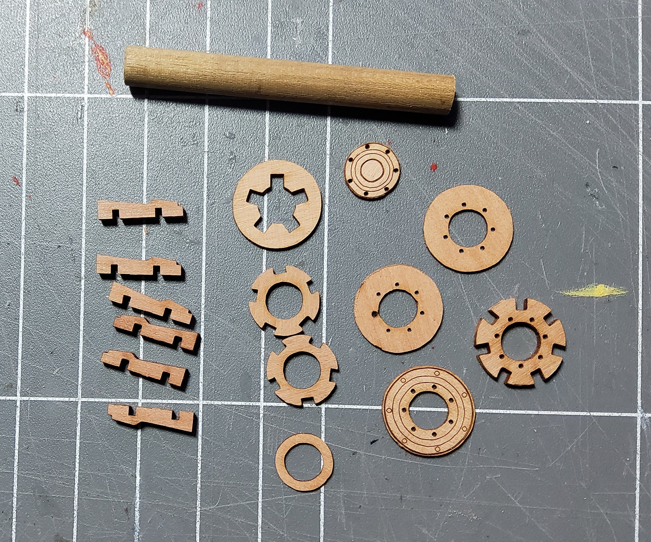
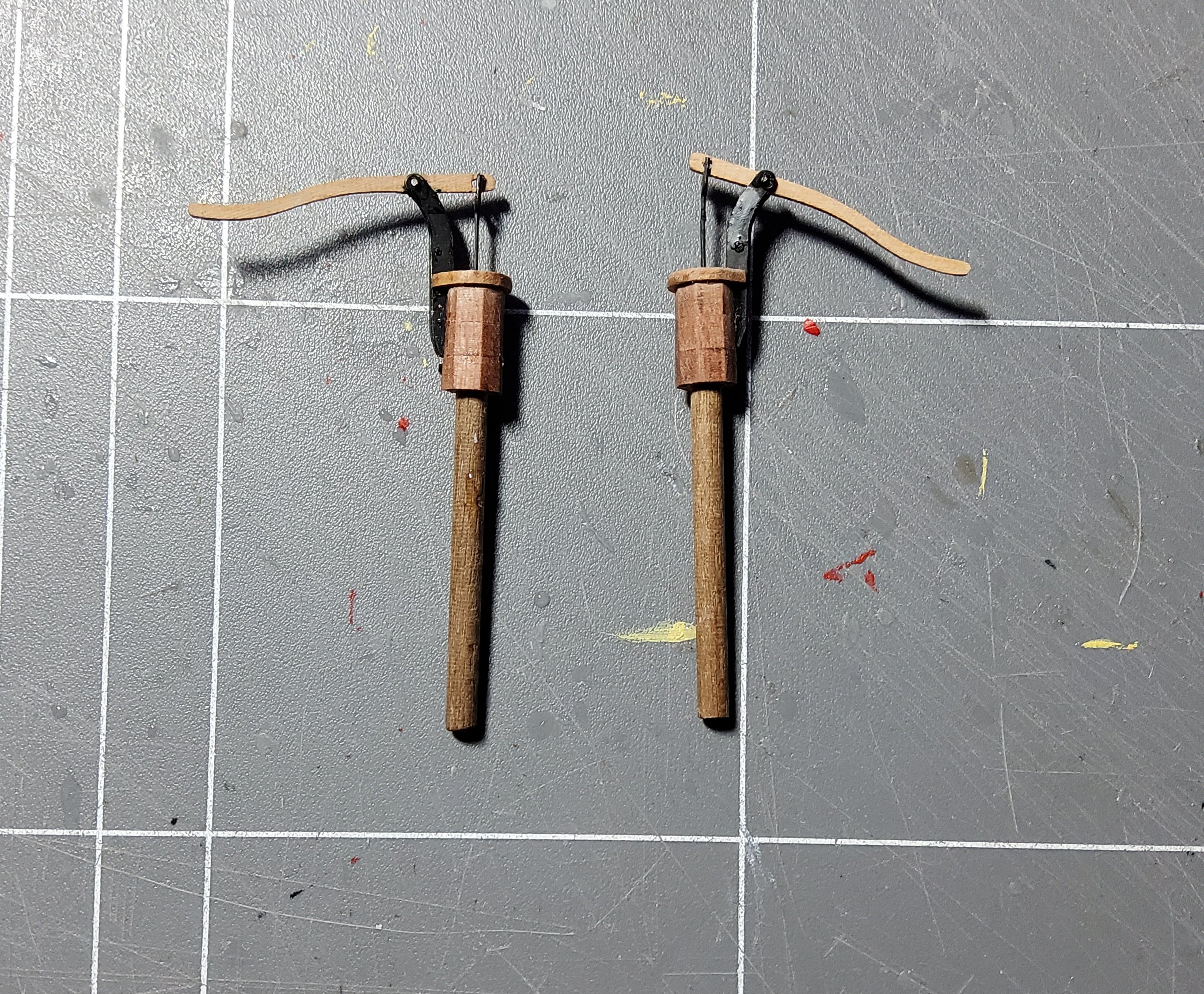
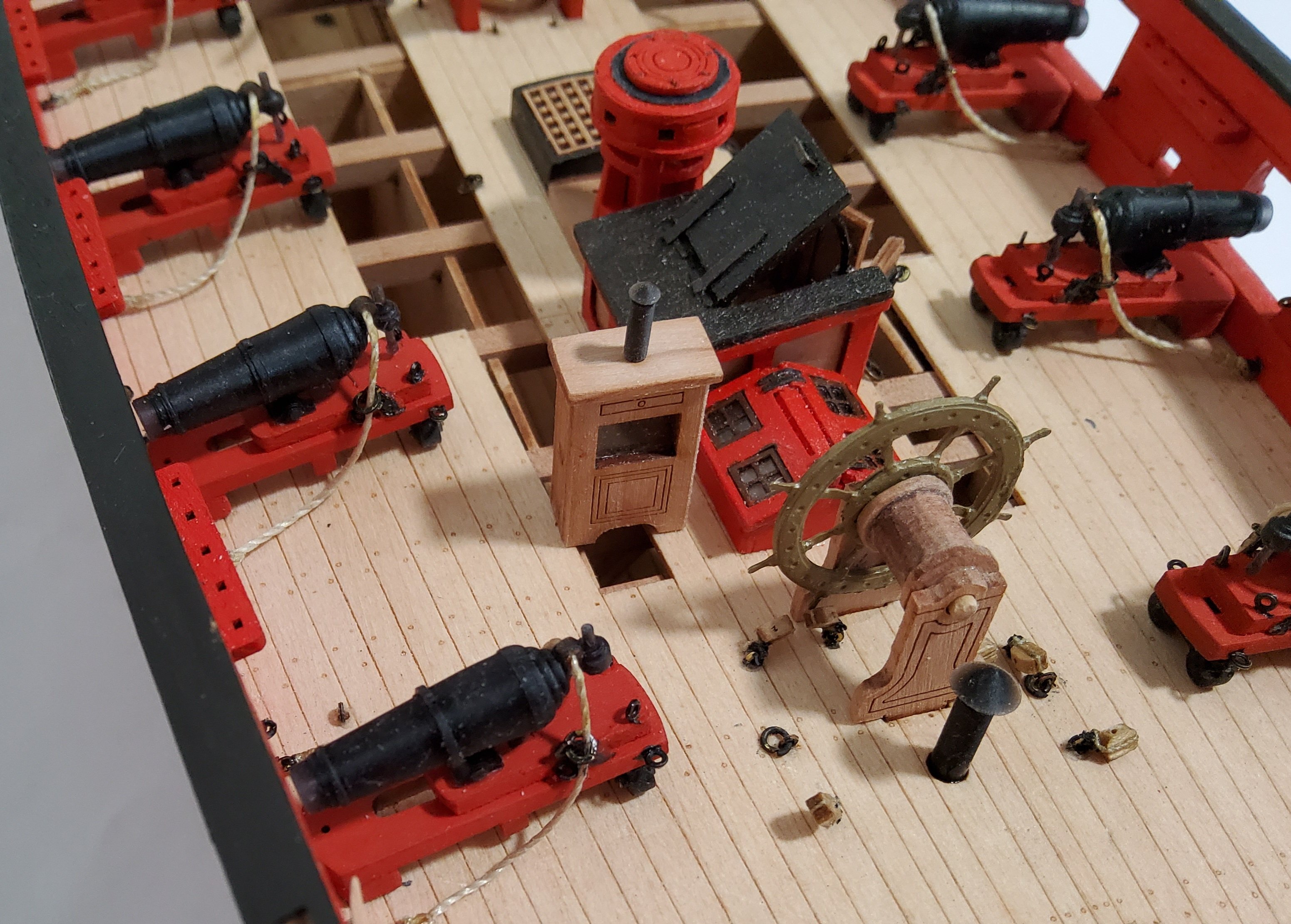
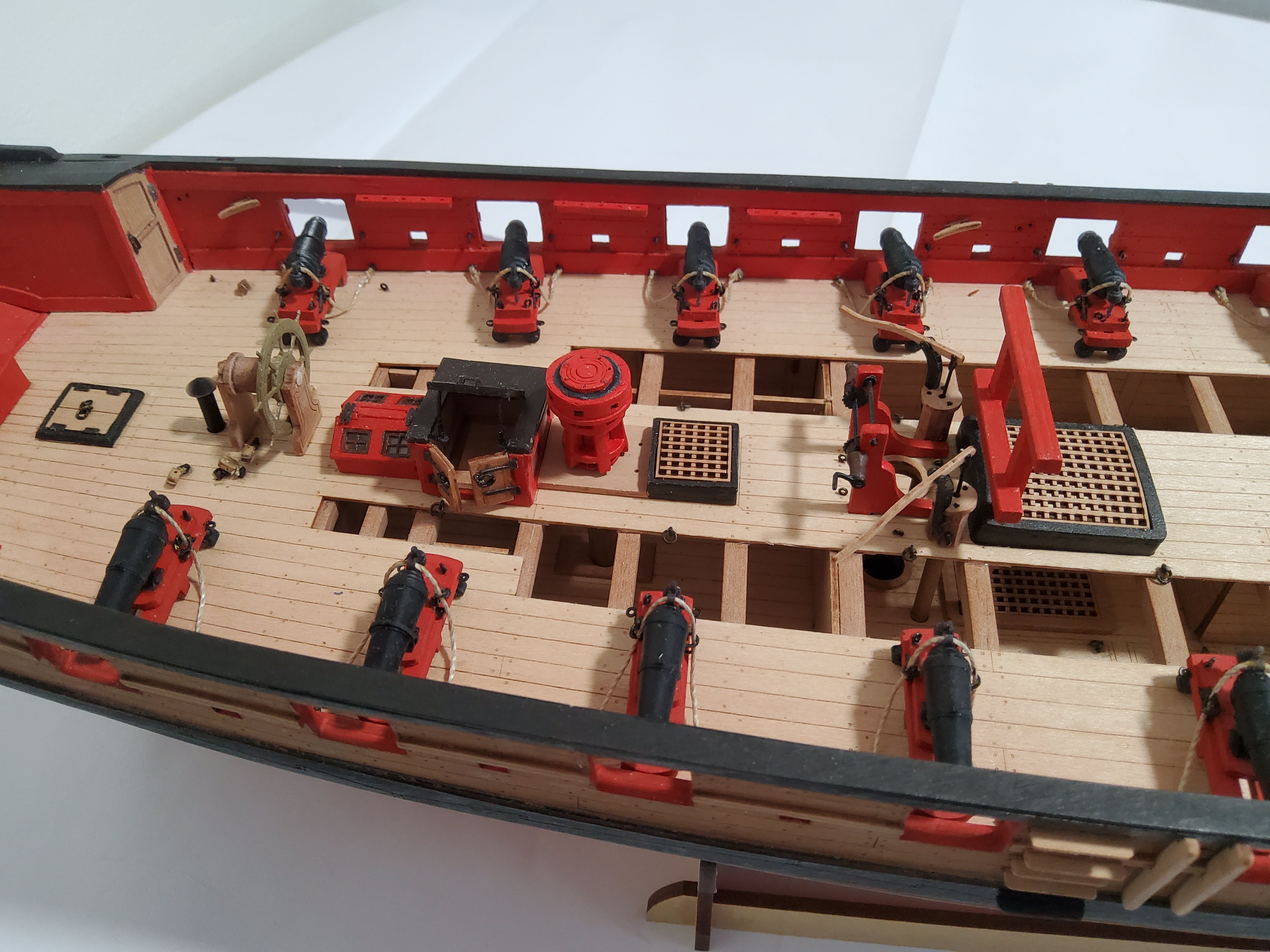
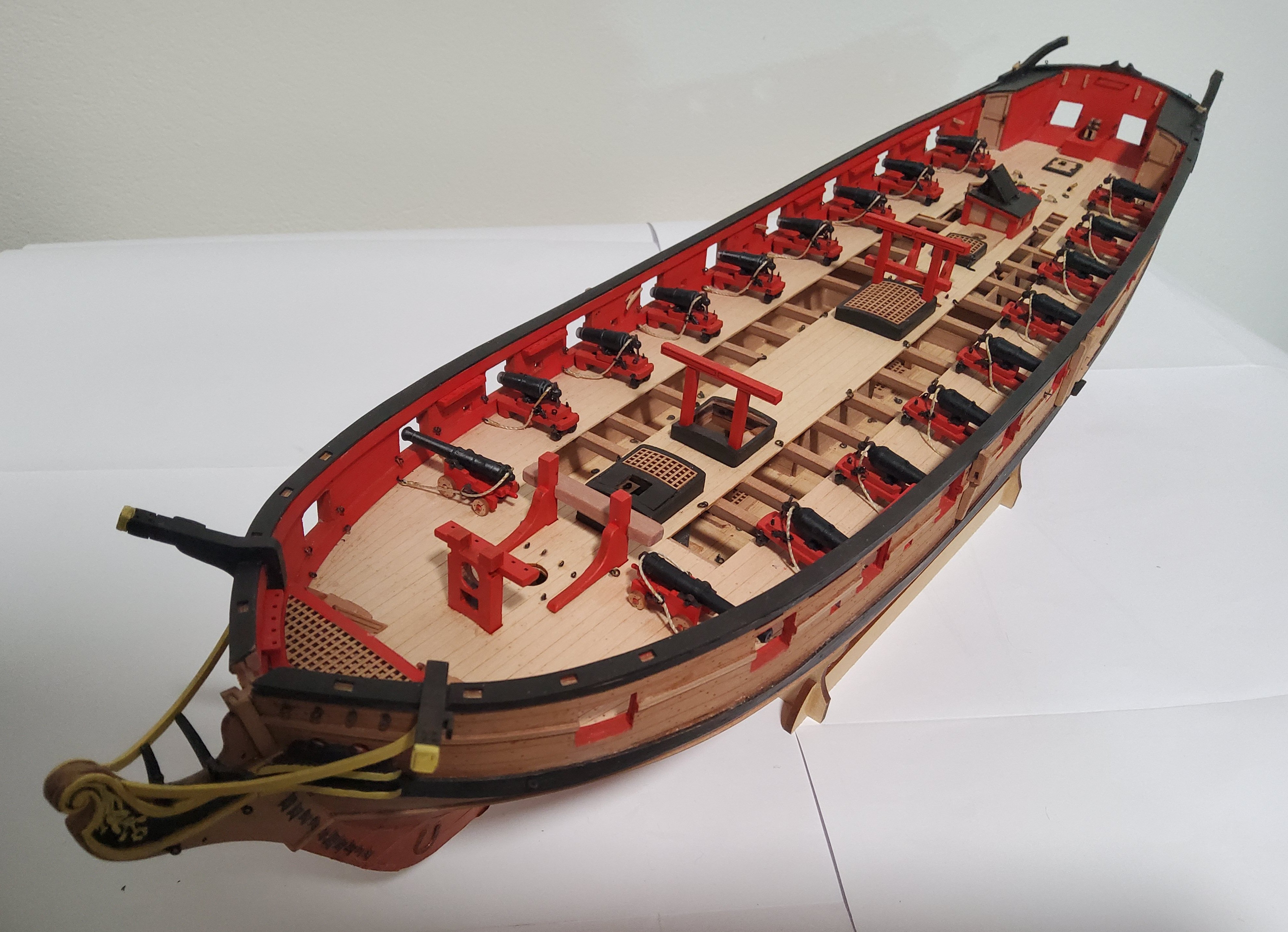
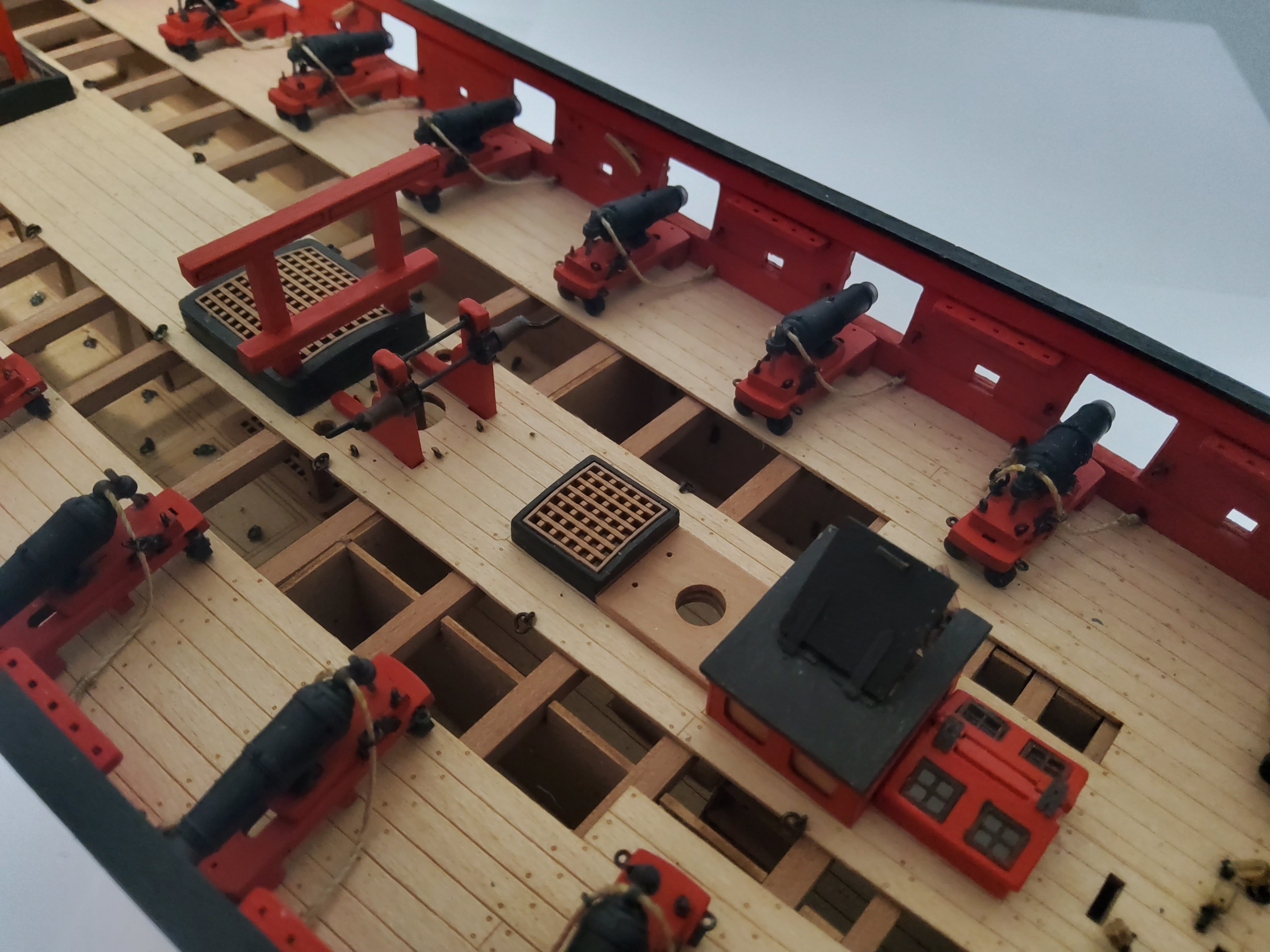
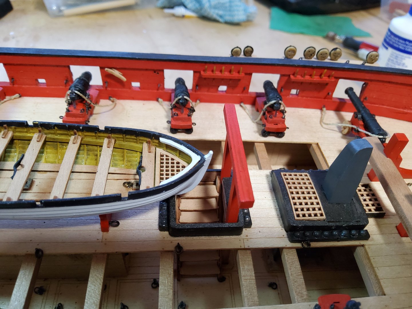
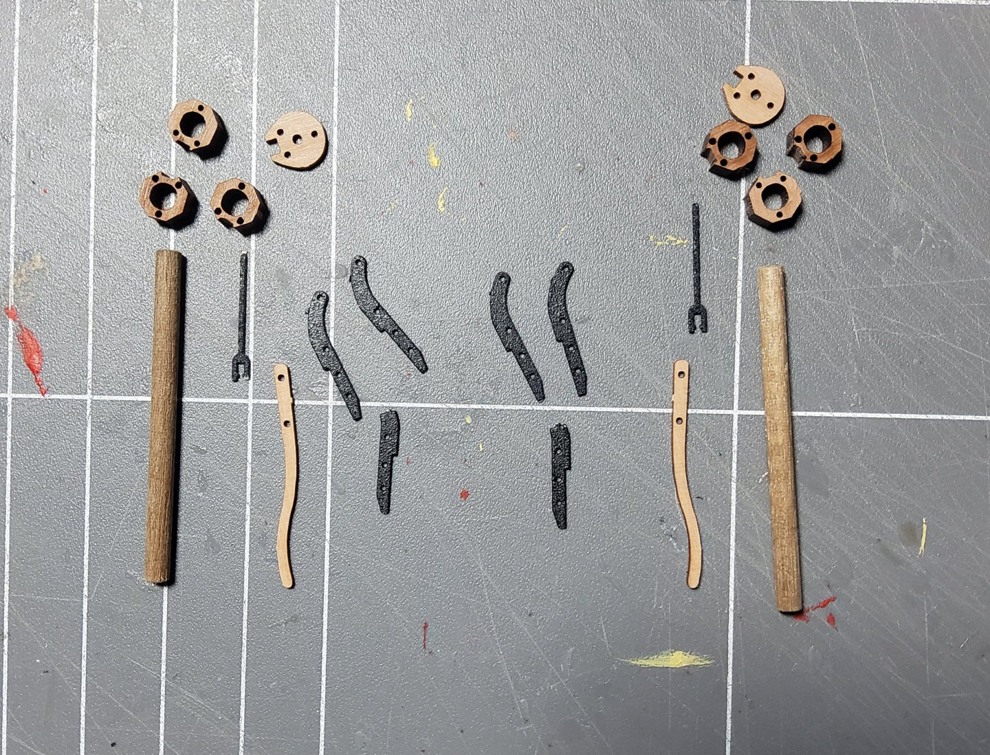
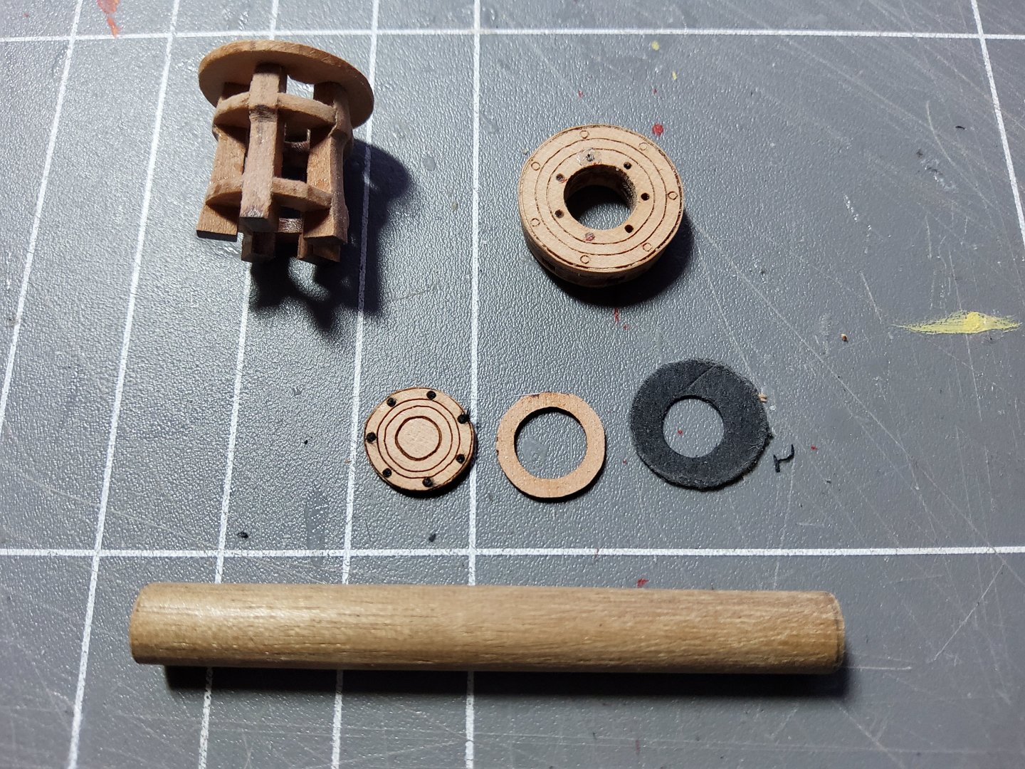
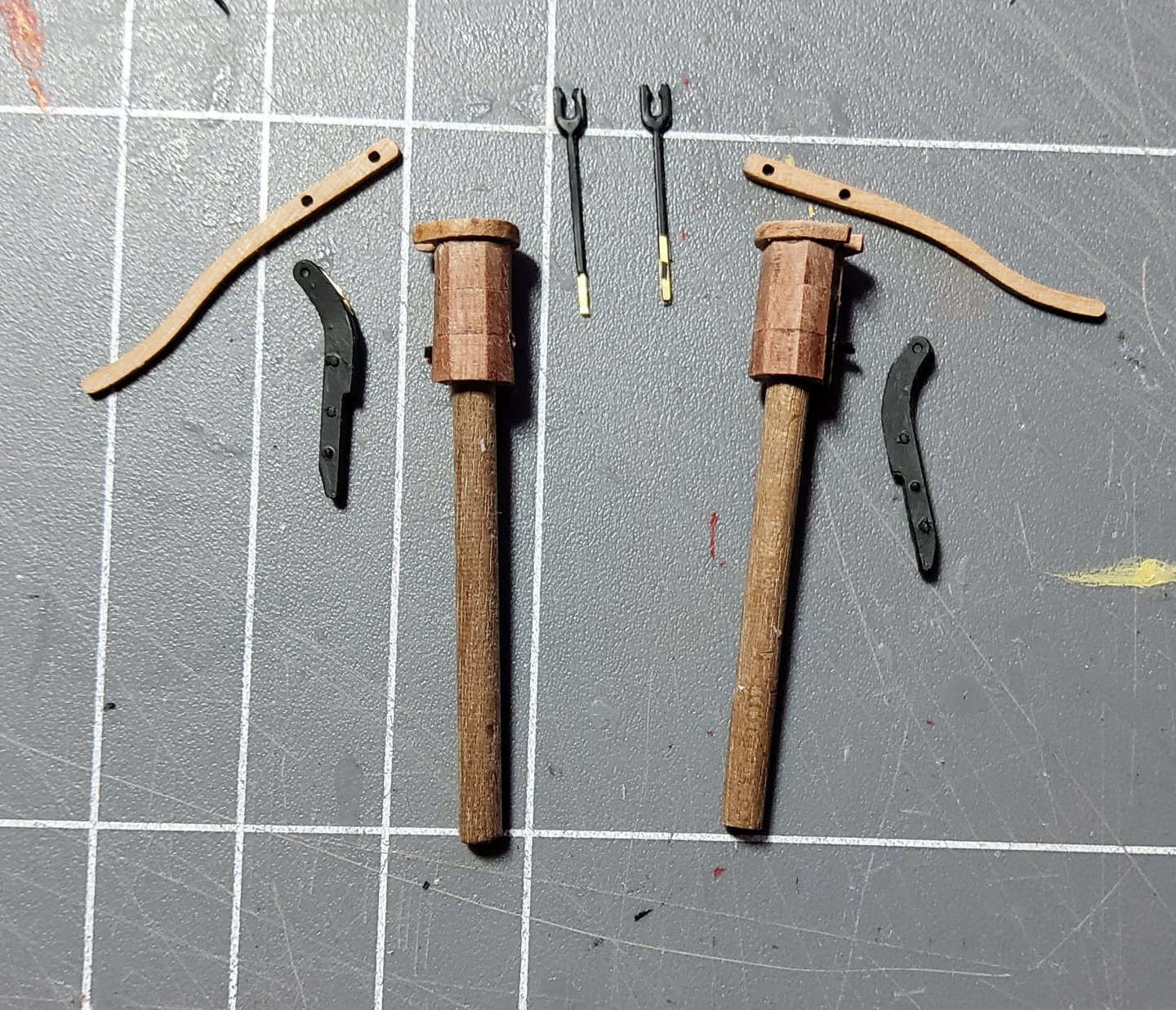
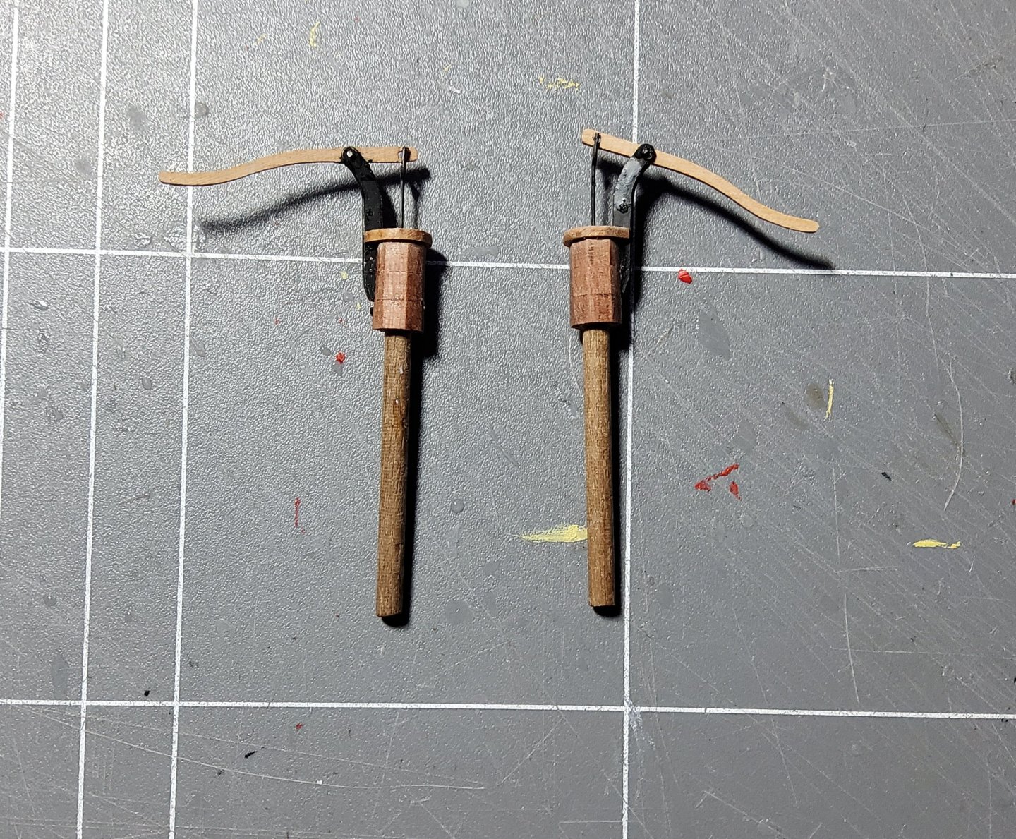
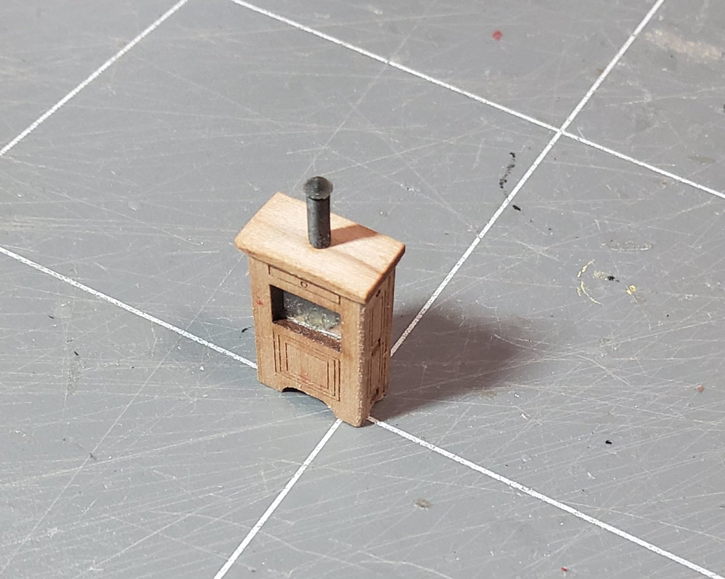
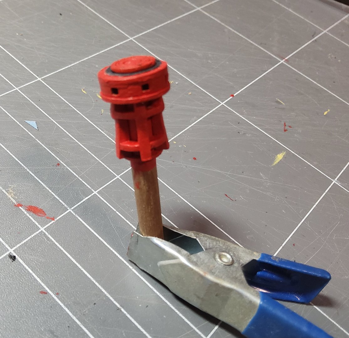
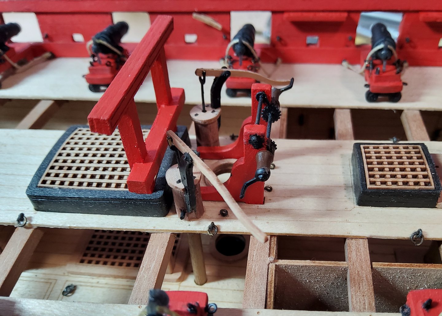
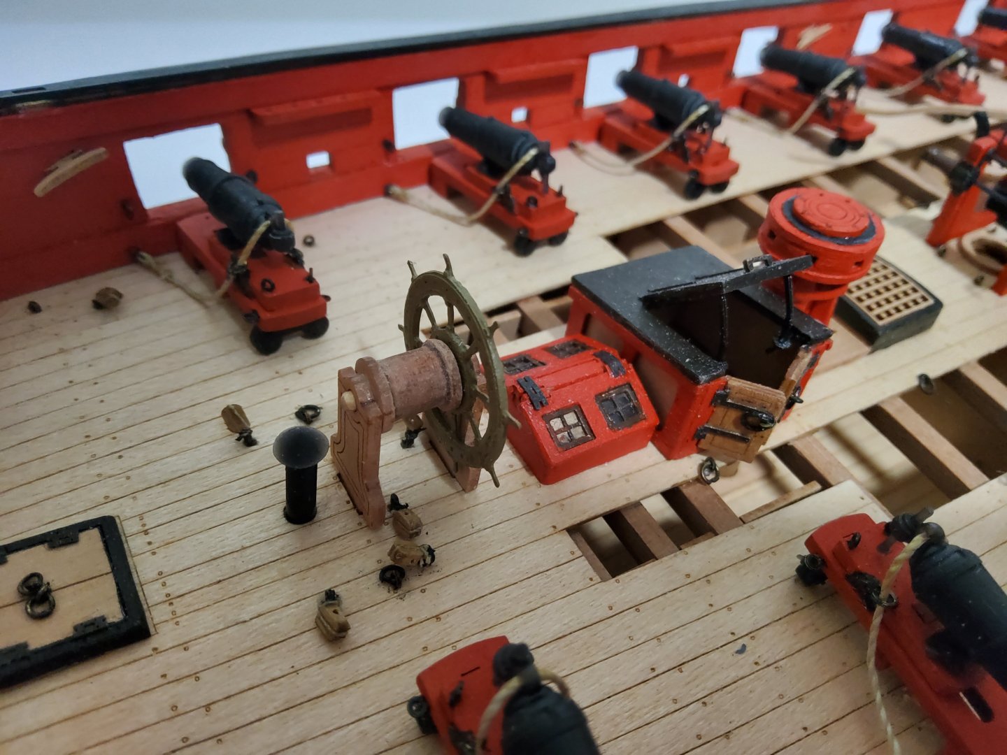
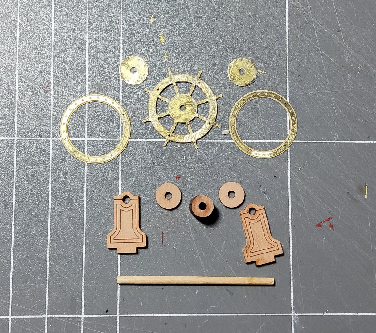
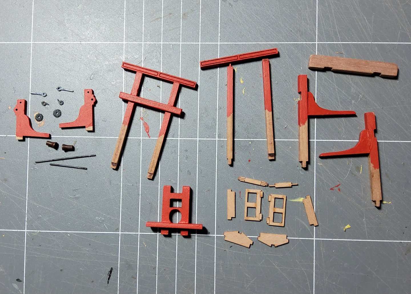
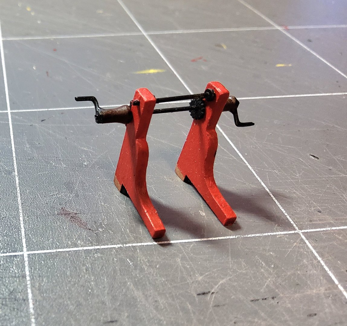
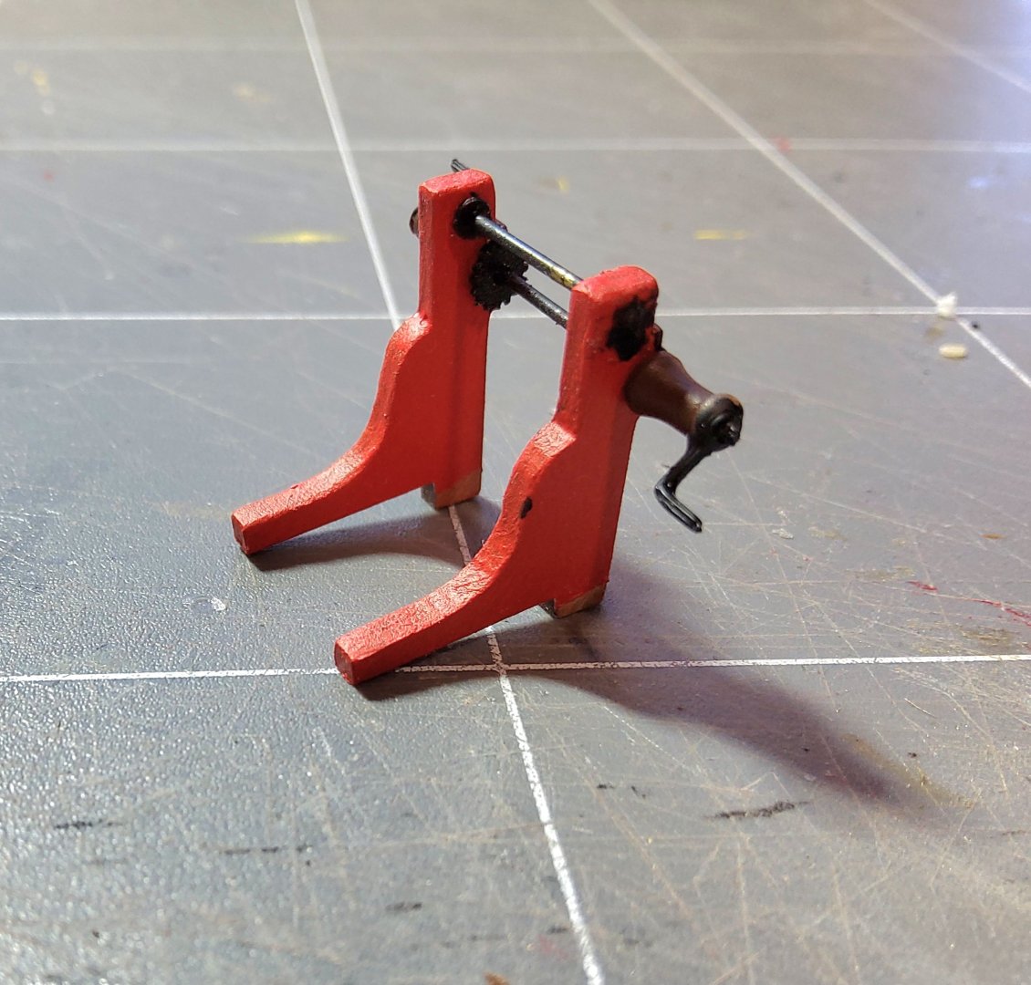
More deck fittings. The two pumps were the first to be done. Parts for the pumps are shown below. The body is hexagonal and made up of three pieces that need to be glued together. The manual says to use a length of dowel to keep the pieces correctly aligned, but also says don't glue these to the dowel, which is to be removed now and replaced later. After thinking about this and looking at the parts and the order in which they were to be assembled, I decided that gluing the three hexagonal pieces to the dowel at this stage was going to work just fine. The length of dowel required (it goes all the way down through the lower deck) was carefully checked first. The top to the body was glued in place and brass pins pushed into the provided holes, representing bolts that hold the body of the pump together. Three brass pieces were glued together with gel CA, with three brass pins providing alignment. The heads of the pins were ground off and the pins trimmed. This stanchion provides the pivot point for the handle, and a pin was pushed through it and the handle. A drop of gel CA was applied at each end of the pin to keep it in place, and it was later trimmed. The pump operating rod was loosely attached to the handle and it extends down into the pump body. As I had the dowel extending right to the top of the pump body, I had to drill a clearance hole to allow the rod to be insered. The pumps almost complete, and completed. Next the capstan. Parts are shown below. As with the pumps, some parts need to be assembled using a dowel to ensure alignment, with the manual saying do not glue the parts to the dowel. The capstan partly assembled. And completed. A piece of black card was used to represent the iron reinforcing ring on top of the drum. The wheel was next, nothing difficult to this. Parts are below and I forgot to take a photo of the assembled fitting. Next the difficult fitting. Not difficult to build, but positioning it is tricky. The binnacle. The parts are below and the finished binnacle below that. I glazed the opening through which the compass could be seen, with a piece of plastic. But where to put it. The manual has it jammed between the wheel and the skylight and facing forward, a position that means the helmsman cannot possibly see the compass. Blue Ensign in his build log has gone into some detail about this. I will probably position the binnacle off to one side and slightly forward of the wheel. Some photos of Harpy with most deck fittings now in place. Cheers


-
Thanks Andrew, much appreciated.
-
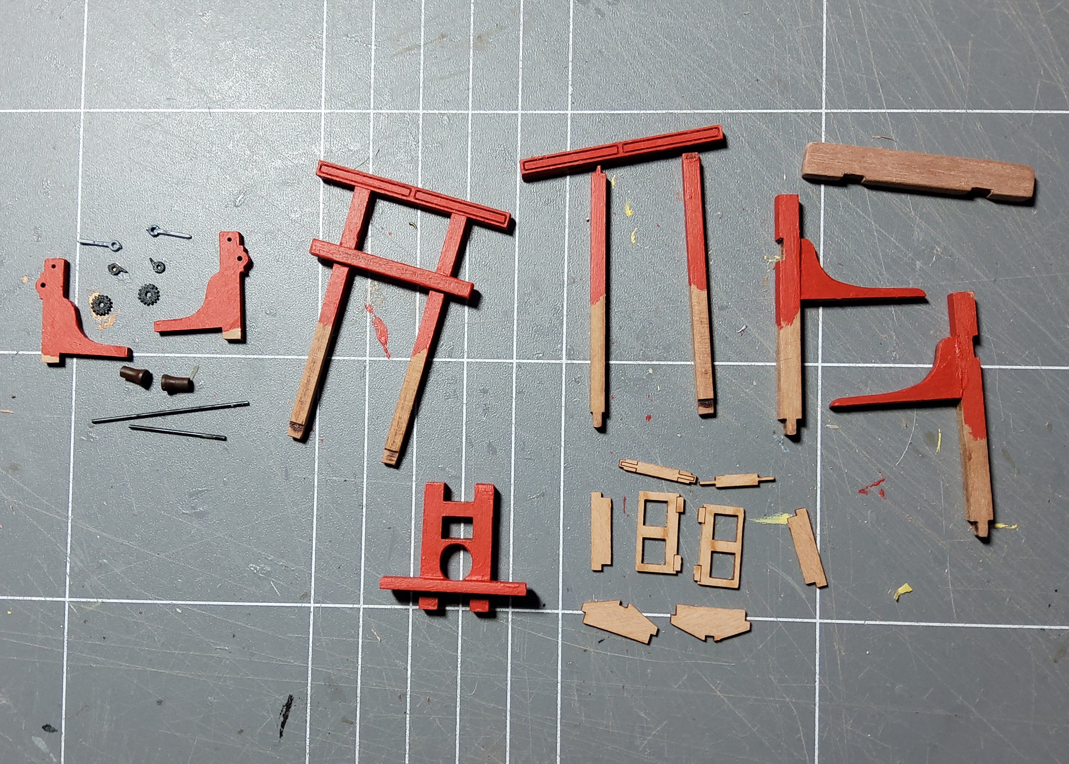
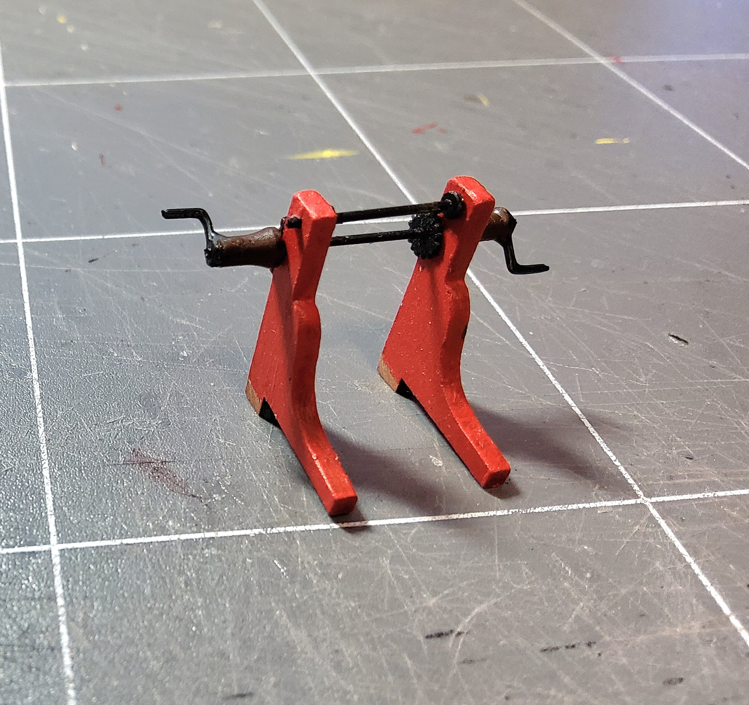
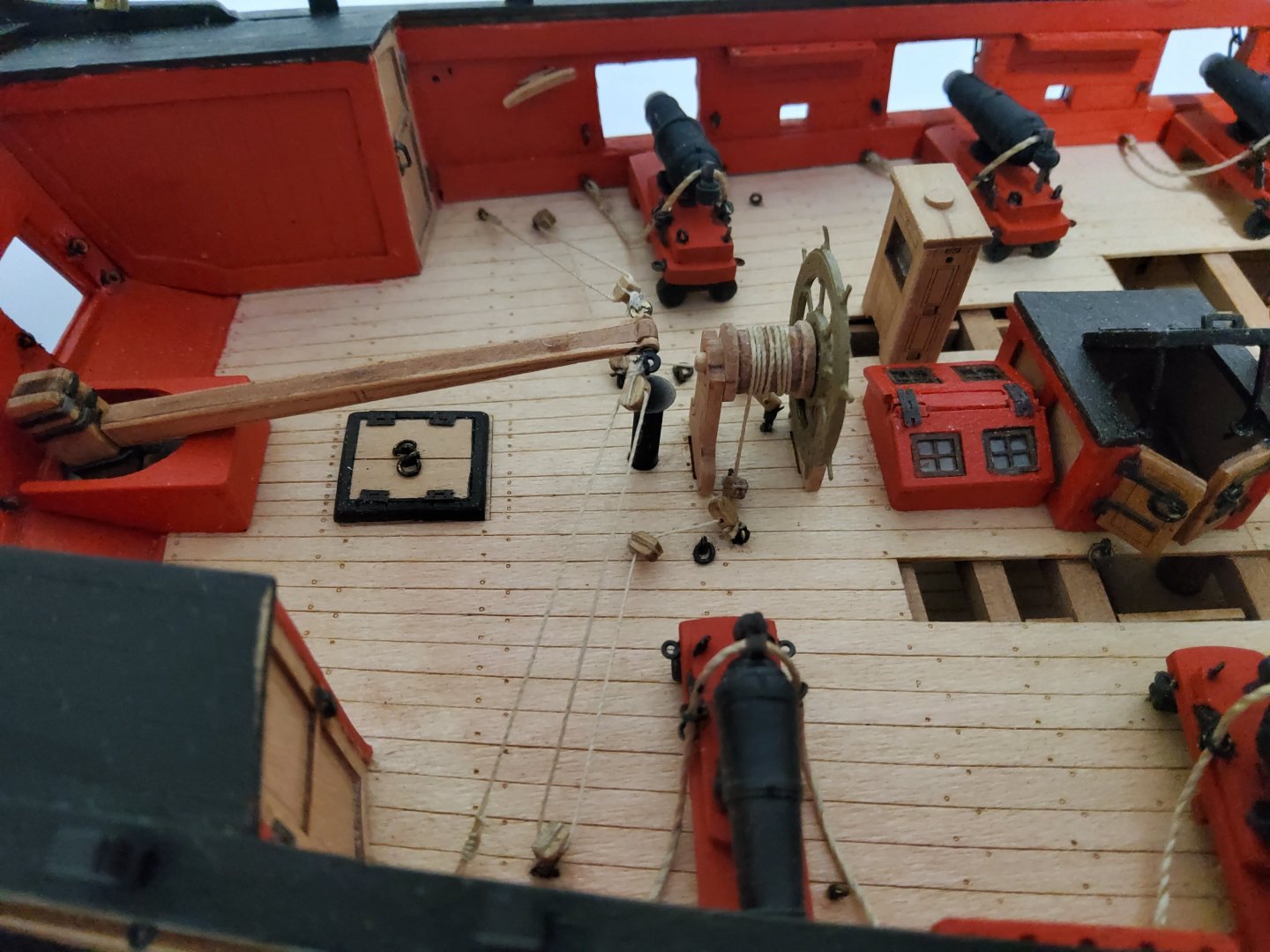
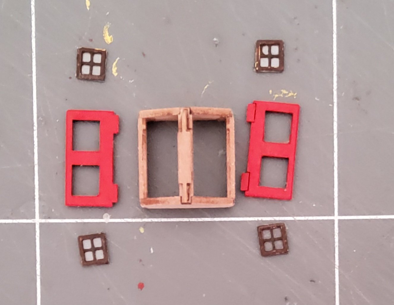
Work proceeds. The photo shows several items, some just from the fret, some partly completed, and others ready for installation. Pieces of the winch are in the top left corner, those for the skylight are in the bottom right corner, there are the two gallows (one complete), the fore bitt and the completed bowspit bitt. Paint has only been applied to the above deck portion of each part. The winch was built partly on the ship, partly off. There are two pices of brass wire required, one 19mm long and the other 32mm long. Both of these are slightly over-long, and if I had simply built the winch off ship, it would not have fitted into the pre-cut slots on the deck. The upper, shorter wire was emplaced in the two side pieces whilst these were fitted into the slots in the deck. These were kept vertical and a small drop of gel CA was applied to the ends of the wire to lock it in place and correctly spaced. This assembly was then removed and the remainder of the parts fitted. Dry fitting of the lower wire was done before final gluing. The ends of the wires were then trimmed. A little bit fiddly, but it turned out quite well. The skylight was done according to the instructions, with the PE window frames painted and backed by clear plastic. These were then pushed into place finishing flush with the outer surface of the skylight hatch. No glue was needed. The photo shows the skylight just before final assembly (the red colour in the photo is a bit off). Some touch up of the paint on the window frames was needed first. The two gallows and the two bitts were easily assembled. All parts now in place on the deck. I have just realised that I have forgotten to add the stove chimney - ah well, a job for tomorrow. Cheers

-
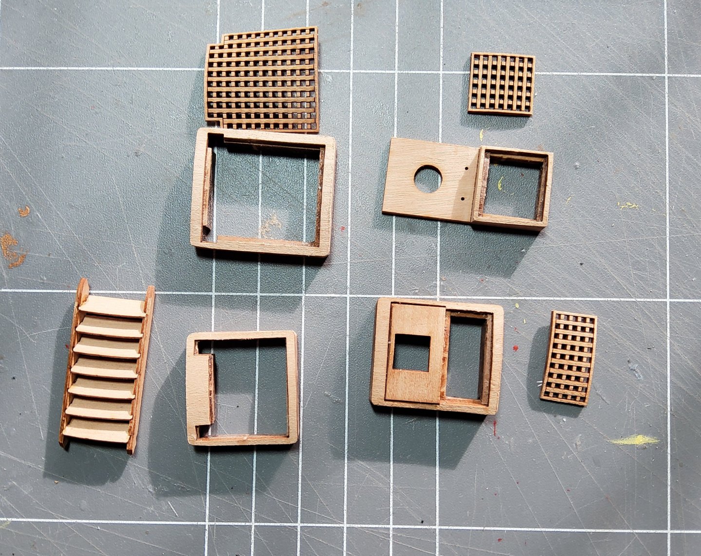
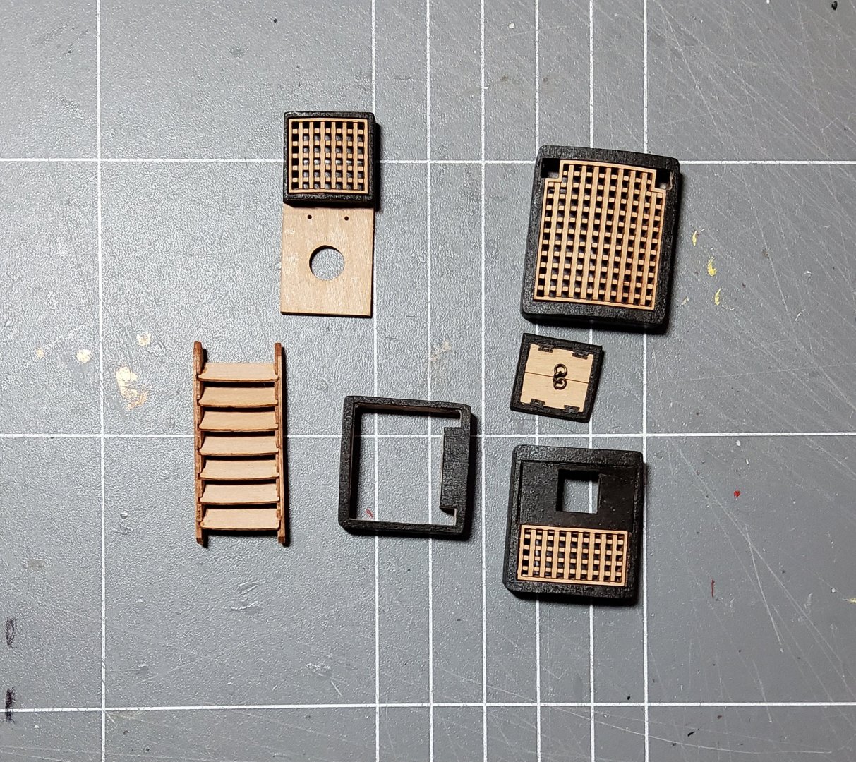
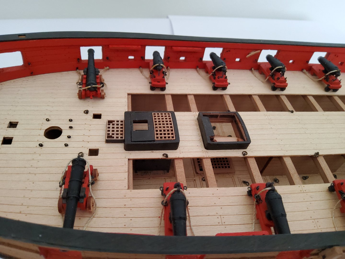
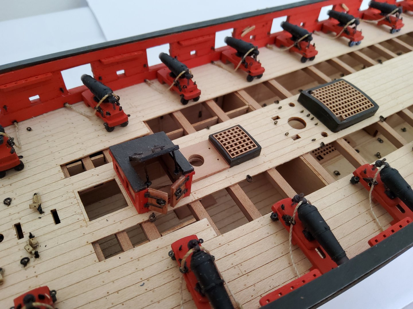
Thanks for all the likes, and to those who have just dropped by. The next job was to add the hatches along the centre of Harpy. The first photo is of the parts for all the hatches plus the completed ladder for the forehatch. The various parts were then painted and assembled. The actual gratings were firstly soaked for a while then bent around a suitably sized cup using masking tape to hold them in place, and left to thoroughly dry. Some of the gratings needed slight, gentle sanding to allow them to fit correctly into the coamings. No issues with that. When dry-fitting the completed hatches into their respective deck cutouts, some slight sanding was required to allow them to seat fully home (and this check should actually have been done before painting the coamings). Again no issue, but as always, dry-fitting before gluing was necessary to check the fitting. Lastly, the ladder for the forehatch was carefully glued in place. A little tricky, but yet again, a couple of dry runs before gluing, sorted out potential problems. The previously completed companionway was also added at this time. Cheers.