HOLIDAY DONATION DRIVE - SUPPORT MSW - DO YOUR PART TO KEEP THIS GREAT FORUM GOING!
×


Richard44
-
Posts
429 -
Joined
-
Last visited
Content Type
Profiles
Forums
Gallery
Events
Everything posted by Richard44
-

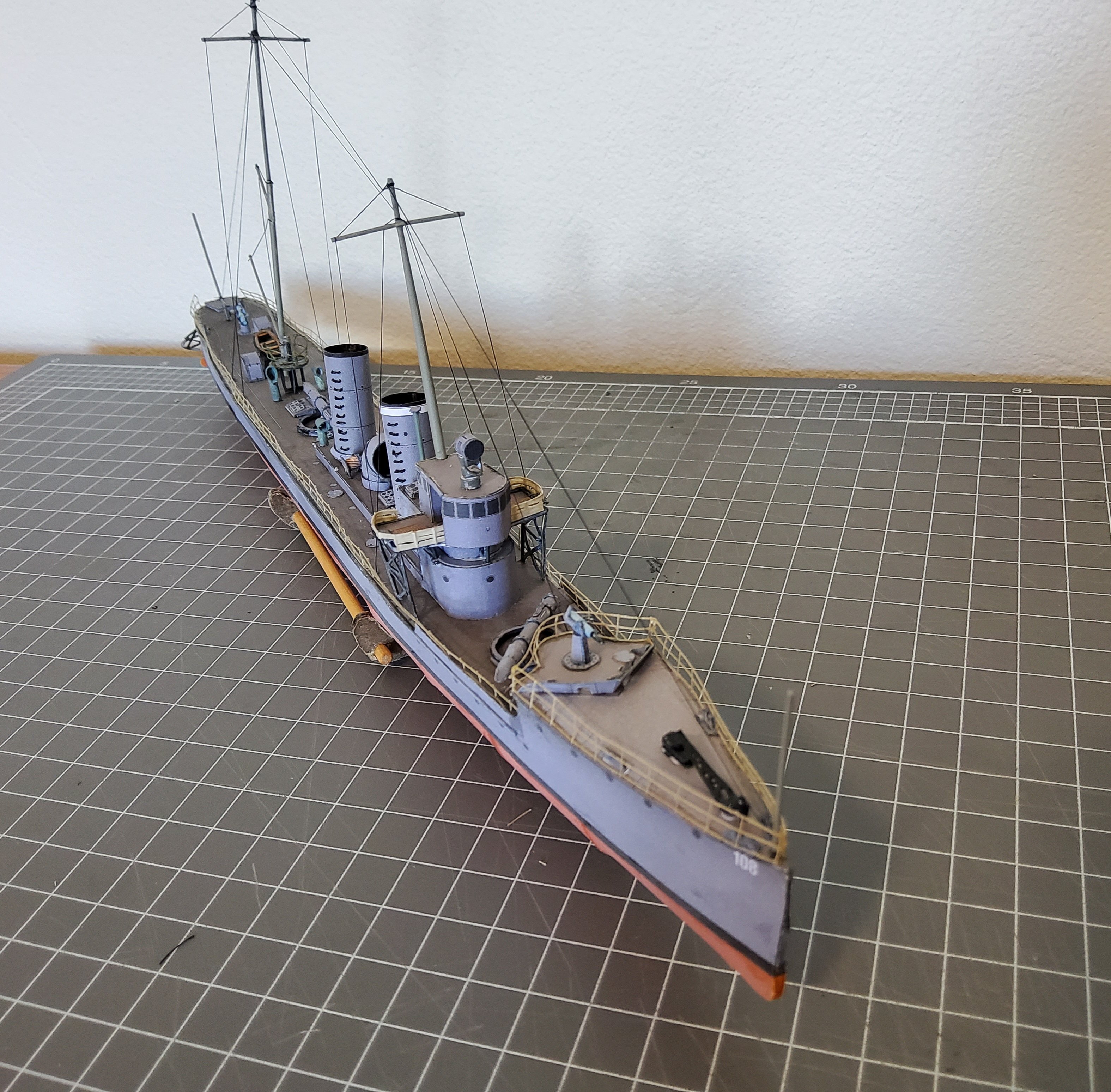
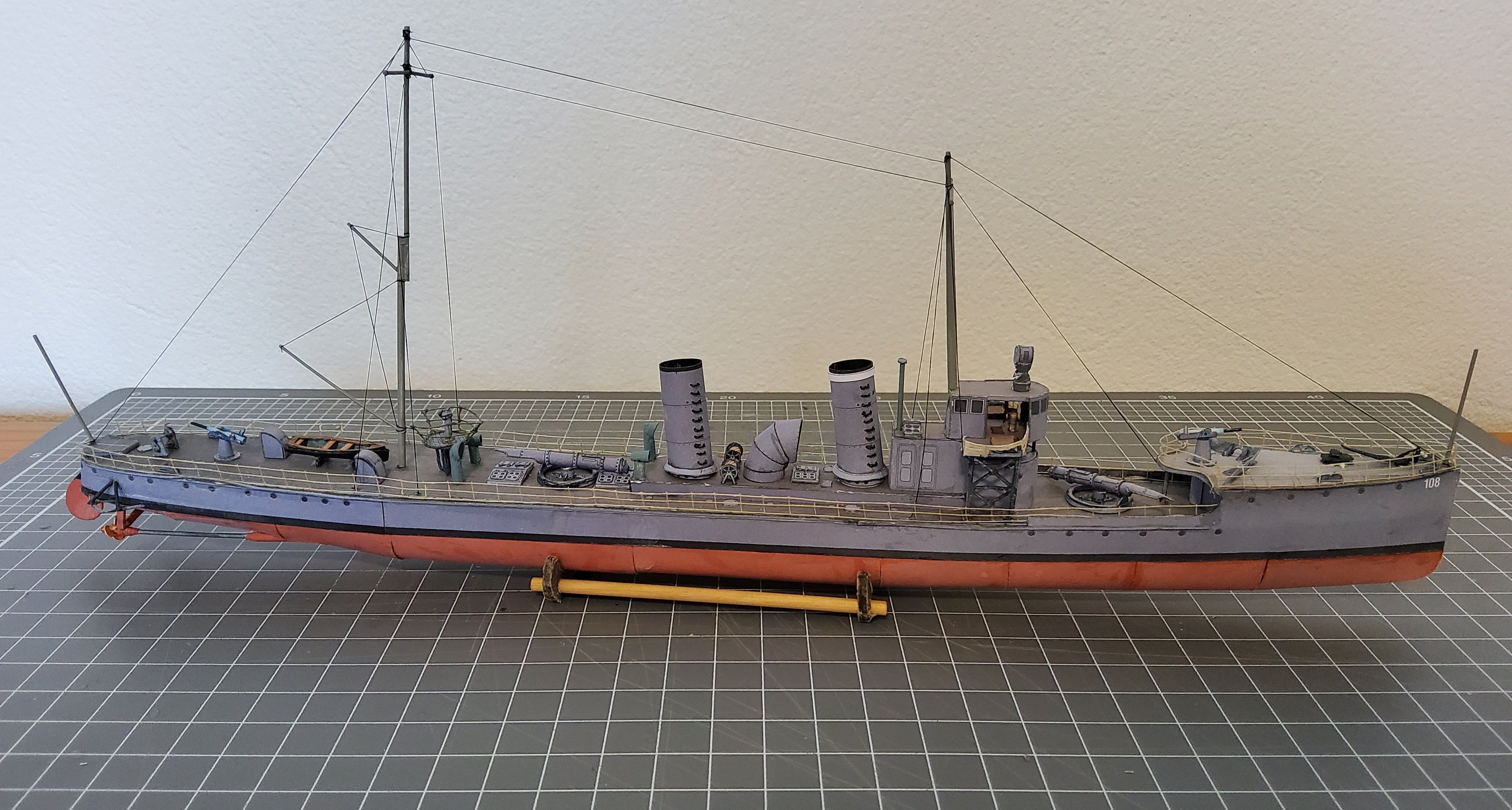
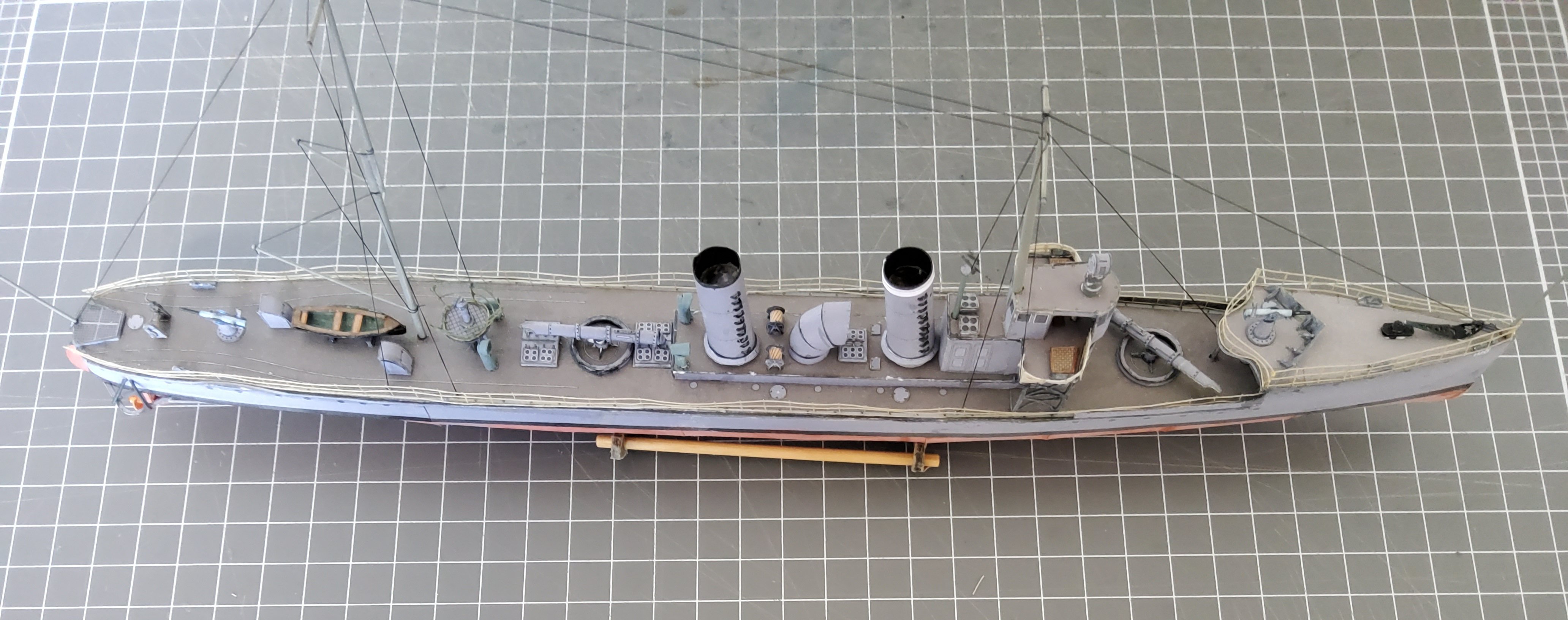
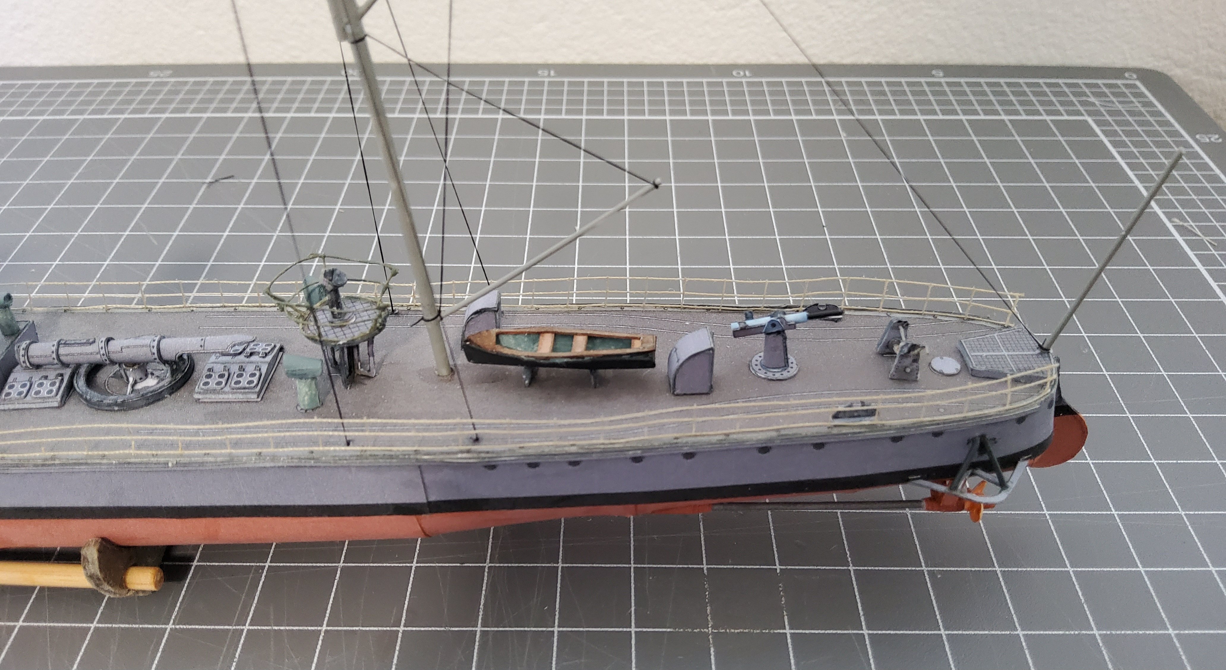
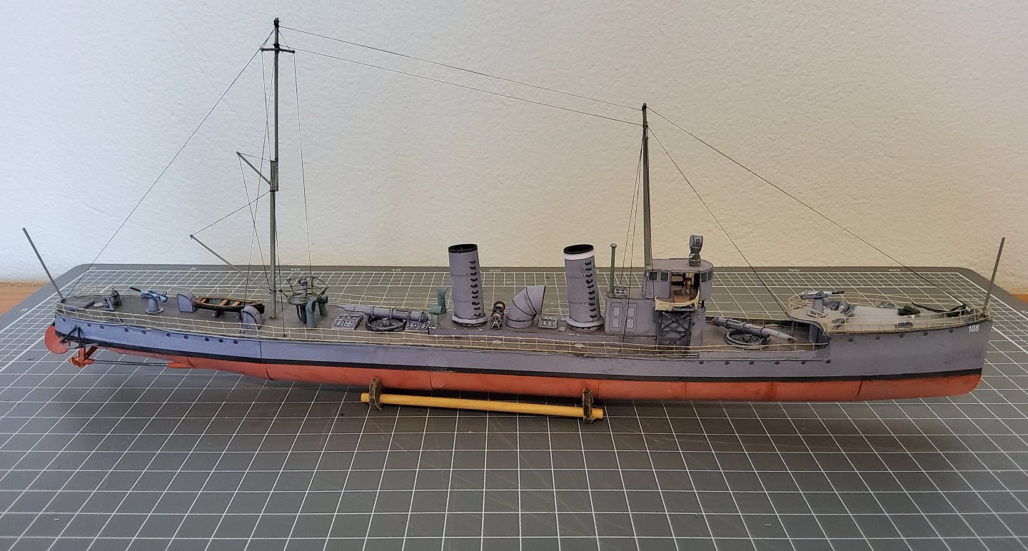
Intro to Card Models Part VIII: Building V108 - Miscellaneous Bits
Richard44 replied to ccoyle's topic in Card and Paper Models
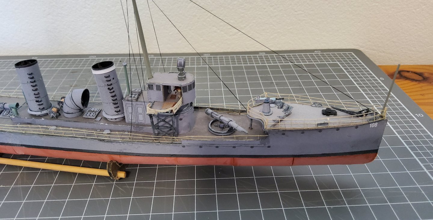
Morning all. There's no build log for my model of the WW1 German torpedo boat, V108. Various factors conspired against me doing this so all I have is a few photos of the completed model. Chris Coyle presented a tutorial on card building using the V108 as the subject. The designer, Digital Navy, allowed the kit to be freely distributed to MSW members and though it is no longer available on the Digital Navy website it can still be downloaded here. I had built several card models but only waterline models, so I decided to try for a full hull, though Chris in his tutorial only builds a waterline V108. It's still a learning curve for me with card models, but my V108 turned out reasonably well with some new techniques being tried (eg thread railings). Cheers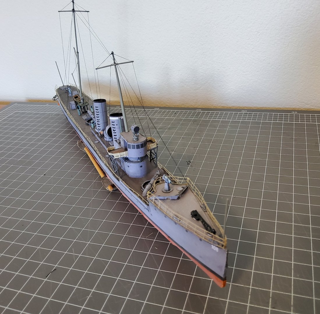


-
Probably referring to common white carpenter's glue, PVA, poly vinyl acetate.
-
I thought that might be the case, but you only find out after you've bought the kit. Whereas Philipp more or less suggests finding out before hand.
-
How do you do this? I could have easily missed something, but I've looked at the Orel website and at some of the models and couldn’t see any reference as to the designer.
-
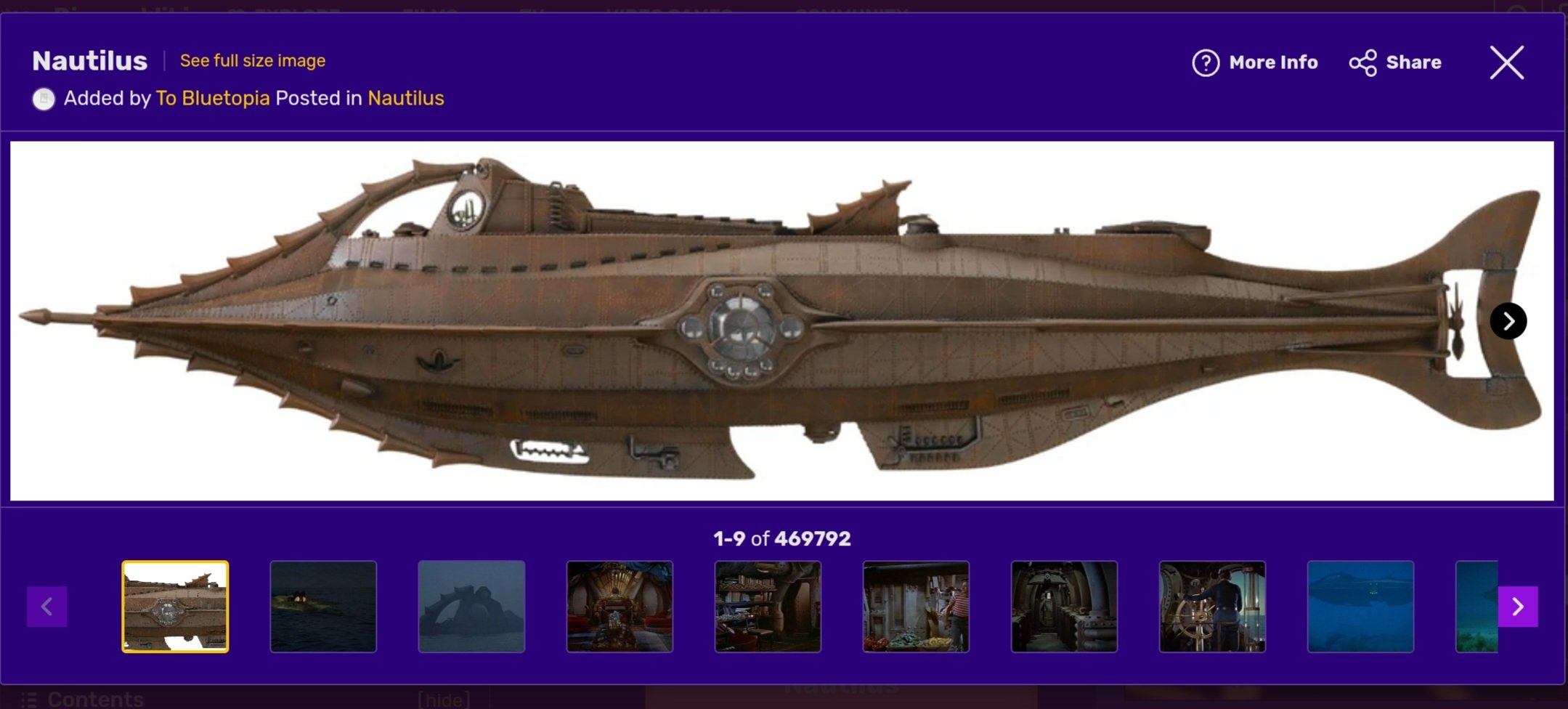
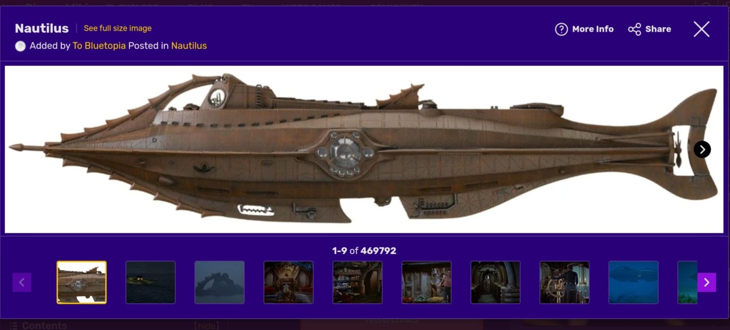
Wow. Very, very different to the Nautilus in the Walt Disney movie. Cheers Edit. Should have added this image.
- 40 replies
-
- 5
-

-
- Nautilus
- Heinkel Models
- (and 2 more)
-
I'm with Keith on this. Use the existing pieces, but before committing, check how much you need to remove where the pieces aren't quite in alignment - it looks to be about 1mm or so. Dry fit a couple of the frames to see if the reduced height of the keel (assuming you do sand the lower/upper edges of the keel) affects their fit. If it looks like everything will be more or less "off", then a new keel from ply would be the answer. Also, I've noticed that you wrapped everything in cling film while glueing and as you have found out, this can obscure what's happening with the glueing. You only need the cling film if there is a chance of accidentally glueing another piece to the two you are joining. You didn't need to use the cling film that shows in the following images. Cheers
- 146 replies
-
- 1
-
-
- Roar Ege
- Billing Boats
- (and 2 more)
-
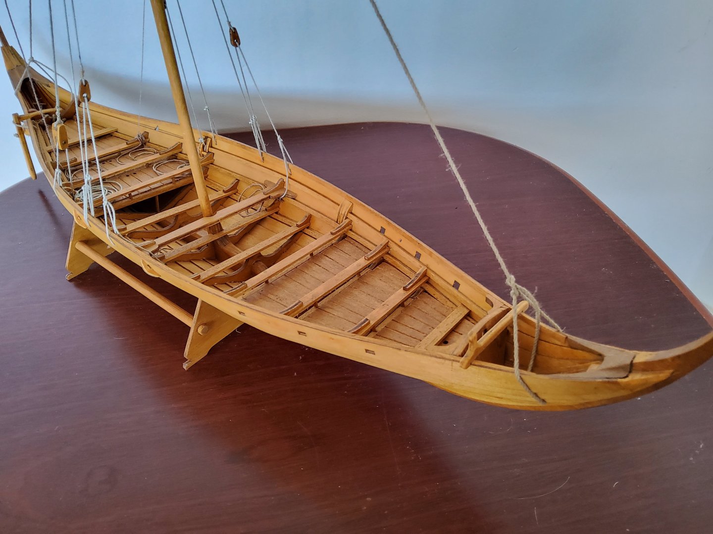
Micha, For what it's worth, I used white PVA (the common one here in Aus is Aquadhere) almost exclusively when building the boat. I may have used CA occasionally. Most of the gluing is easy enough. For the planking, I ran a thin bead of glue along the top edge of a plank, clamped (pegs work well) the next plank to it and wiped off excess glue, moving the clamps as required to do this. Good luck with your build. Edit. I should have added this. The only joints on this boat that will be under any sort of stress are those associated with the planking. The planks are already spiled, and if you fit the planks before gluing, the stresses will be minimal. You do not need a super strong glue. Cheers
- 146 replies
-
- 2
-
-

-
- Roar Ege
- Billing Boats
- (and 2 more)
-
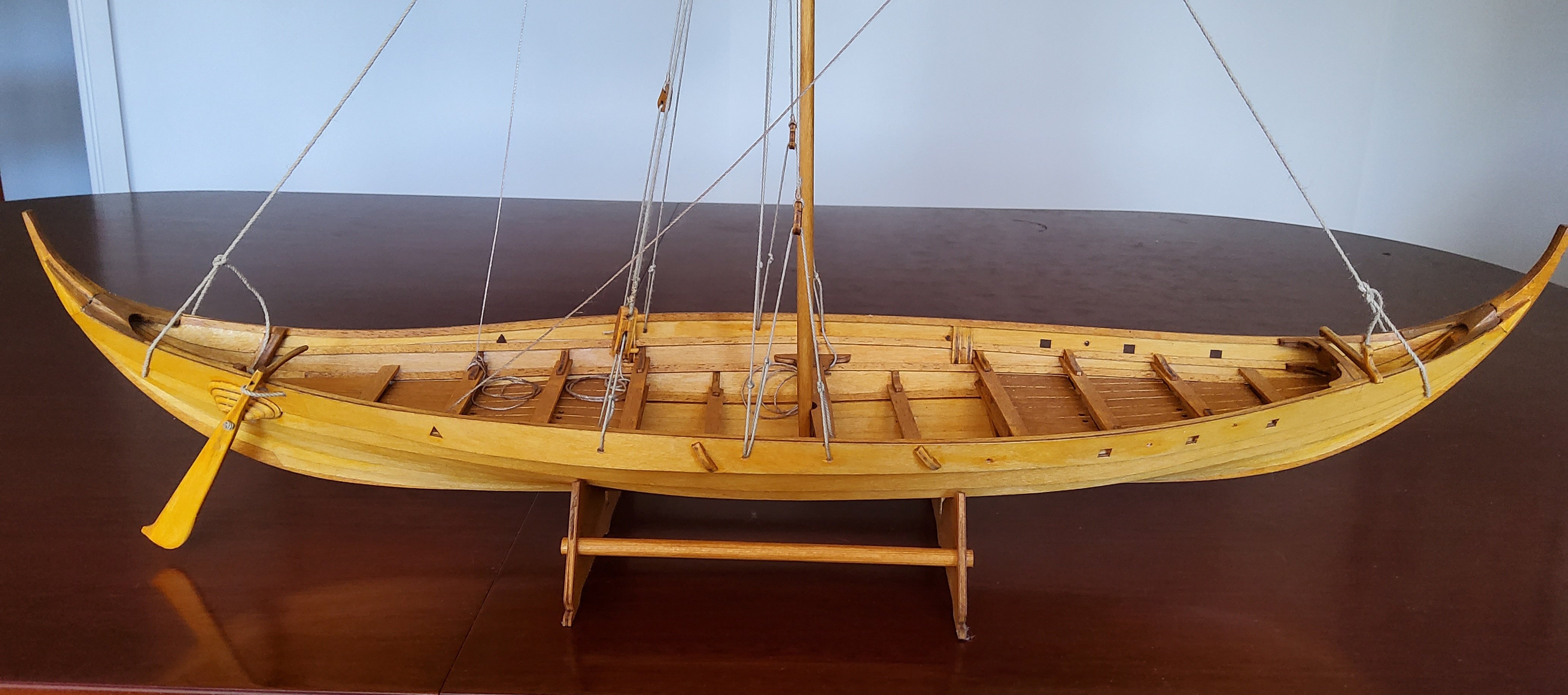
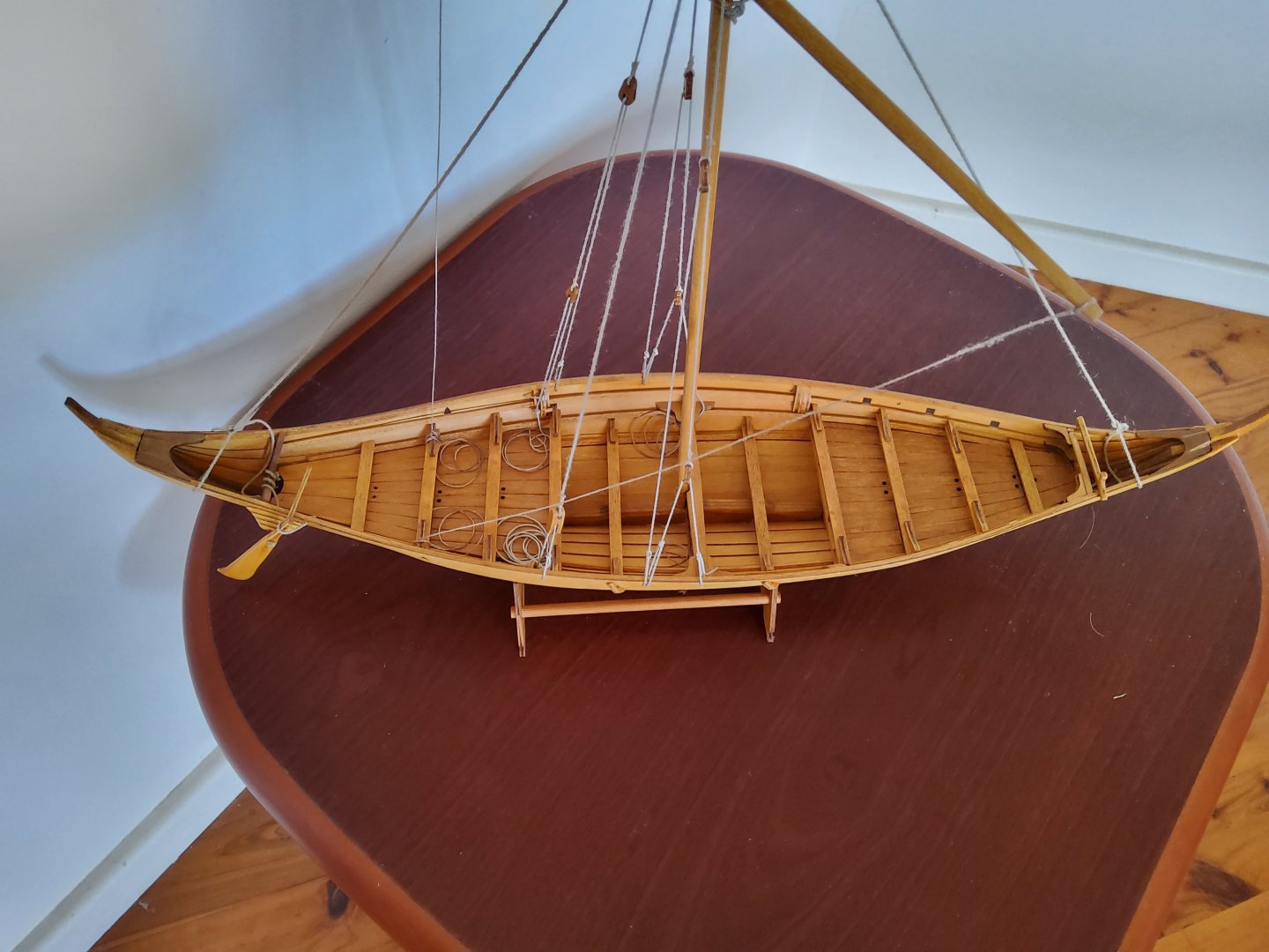
Hi Micha, I thought that I would show you a few photos of my Roar Ege. Unfortunately, there is no build log as I built it before joining MSW ☹️. Probably can't help much with questions either 🥴 as the build was quite a while ago. The kit does make into a nice model. Enjoy. Cheers

- 146 replies
-
- 5
-
-
- Roar Ege
- Billing Boats
- (and 2 more)
-
Chopper Lesson Learned
Richard44 replied to Todd Hart's topic in Modeling tools and Workshop Equipment
Hi Jaager, The screws are now metal, but it is fiddly trying to get that sweet spot. I had no trouble with stock moving around, but I was only ever cutting small sectioned wood. It's not perfect, but it worked for me. Cheers -
Chopper Lesson Learned
Richard44 replied to Todd Hart's topic in Modeling tools and Workshop Equipment
I fastened mine to a board, then fashioned a moveable stop from aluminium (aluminum 😁) angle so that I could cut multiple pieces all the same length. Cheers -
Hi Alex, I don't actually live in the Blue Mountains, I live at Gosford. I travel to the BlueM occasionally for bushwalks. That's a great looking model you've got. Cheers
-
Chopper Lesson Learned
Richard44 replied to Todd Hart's topic in Modeling tools and Workshop Equipment
You could look at this tool. I have one and it works very well. https://www.micromark.com/Miter-Rite Cheers -
After drinking a bottle of schnapps, I can well understand your confusion - clearly I meant along the bottle, not around it 😁😁 Cheers
- 63 replies
-
- 2
-
-
- card
- Revenue Cutter
- (and 2 more)
-
Wind the thread gently around a dowel 10 times, measure the length, divide by 10.🙂
- 63 replies
-
- 1
-
-
- card
- Revenue Cutter
- (and 2 more)
-
Kpfw VI Tiger I ?? 🙂🙂 Cheers
-
Hi Alex, welcome. What part of the Blue Mountains are you from? I've just done a bushwalk at Lawson. Cheers
-
Chris, Do you seal in any way the edges of the frames before sanding? I usually wind up with very fuzzy edges and have been thinking of soaking the edges with dilute PVA beforehand - not CA as I don't think PVA will adhere to the frame later when the skin (or whatever) is attached. Thanks. Cheers
-
Don't know if it would work, but you could try printing by stretching and fastening the silkspan onto a sheet of paper. Laser printer might work better than ink jet.
-
You could try moistening the frame first - the moisture triggers the CA. One problem may be the wood itself. Some woods are slightly oily and CA doesn't like it. Best of luck.
- 68 replies
-
- 1
-
-
- Sanson
- Artesania Latina
- (and 2 more)
-
That’s looking very nice indeed.
-
Hi Mike, I see that you've just looked at my build log, so you know that the outside of the hull was painted, but most of the rest of the boat was left natural. 🙂. I now have no idea where I got the colour scheme from - I think it is fairly typical of boats of that time. Cheers
-
You really do wonderful, painstaking work. Amazing.
-
And thanks to everybody who followed this build, "liked" it, or made comments. Very much appreciated. Cheers
-
Thanks Alan, OC, Andrew, GrandpaPhil, Rob and Chris.🙂 It was certainly an interesting build, now on to the next build, probably a boat. Cheers PS. Thanks Chris for correcting the title, one of these days I'll get it completely correct.🥴😁
- 28 replies
-
- 10
-
-
Hi, Ken That was only my guess. The only photos I found of that radiator arrangement didn't help with seeing where the lines went. Cheers