HOLIDAY DONATION DRIVE - SUPPORT MSW - DO YOUR PART TO KEEP THIS GREAT FORUM GOING!
×


Richard44
-
Posts
429 -
Joined
-
Last visited
Content Type
Profiles
Forums
Gallery
Events
Everything posted by Richard44
-
 I'll try for the wheels down. I can always use the photo copied pages for a second go 😁. Wheels though, not easy to make realistic looking ones 😬.
 -
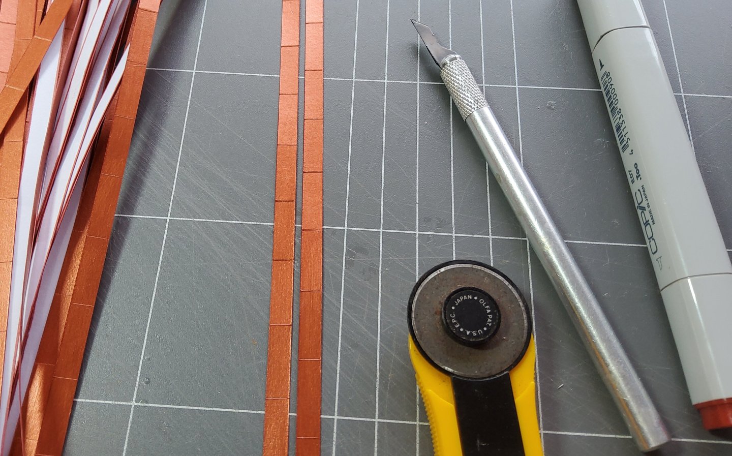
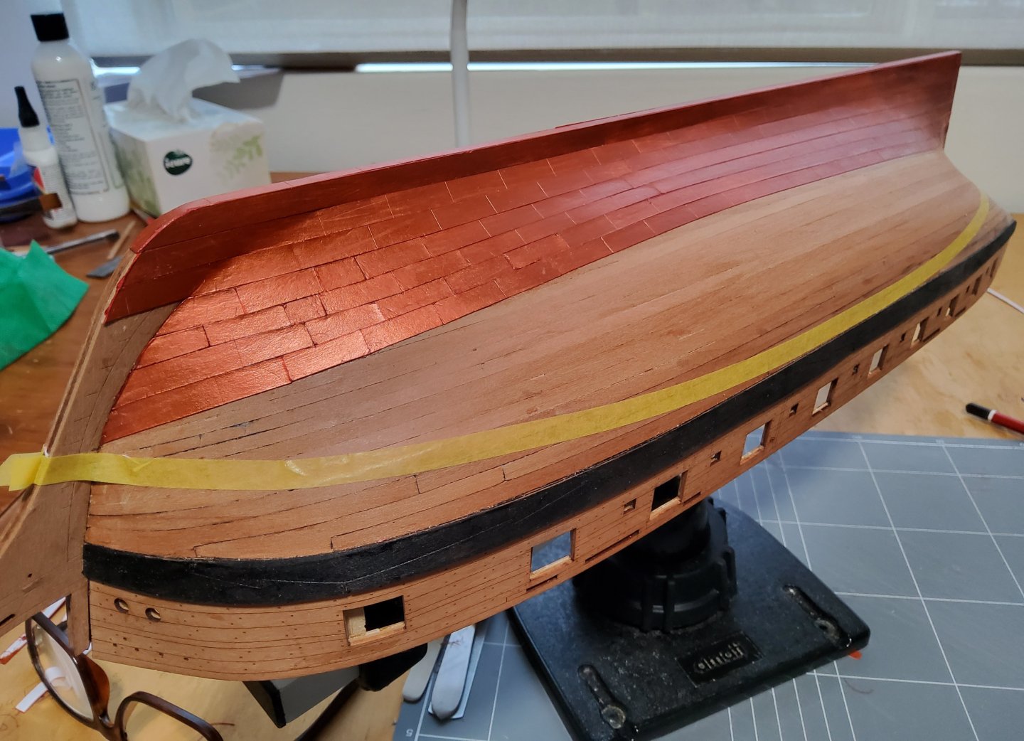
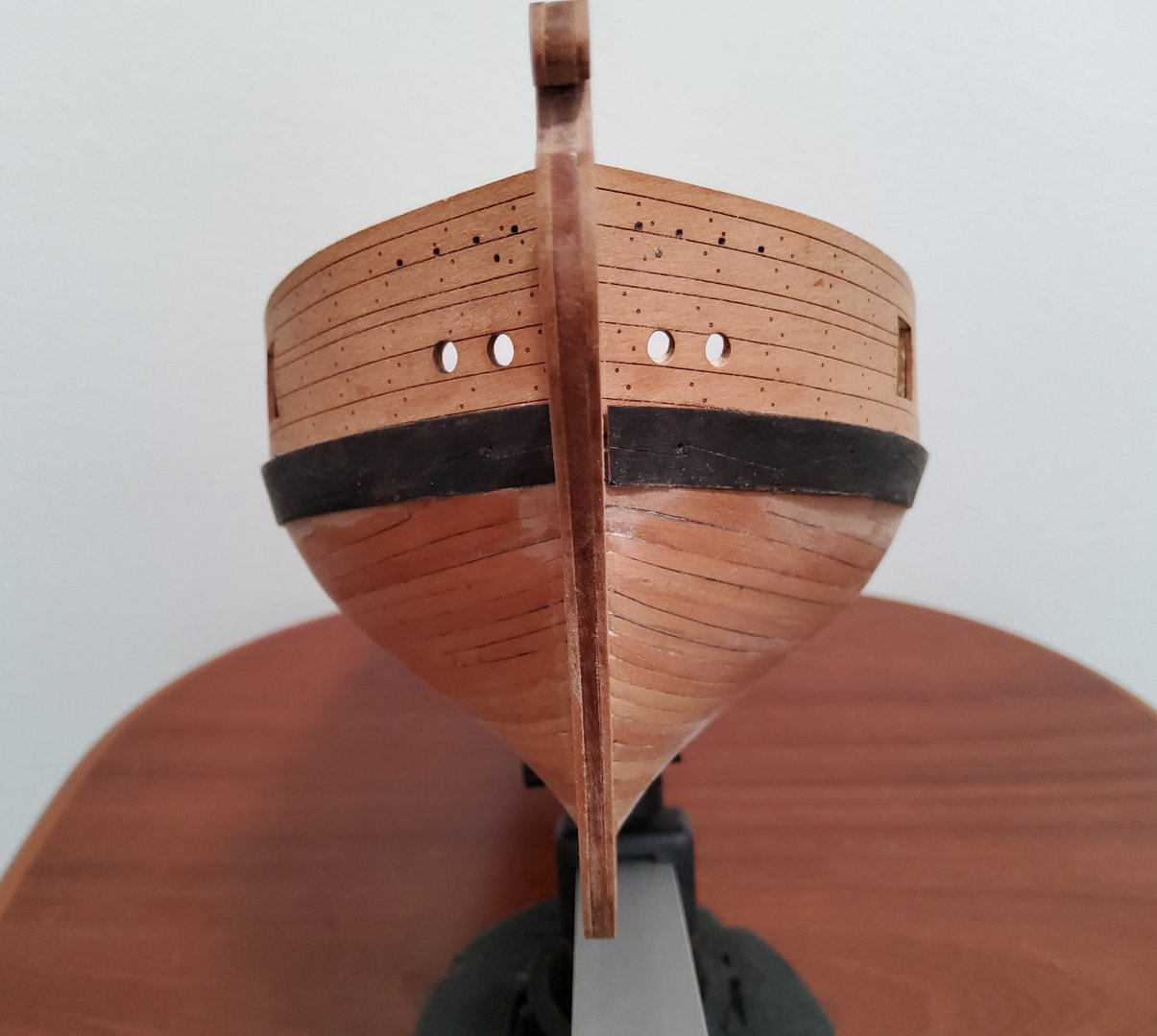
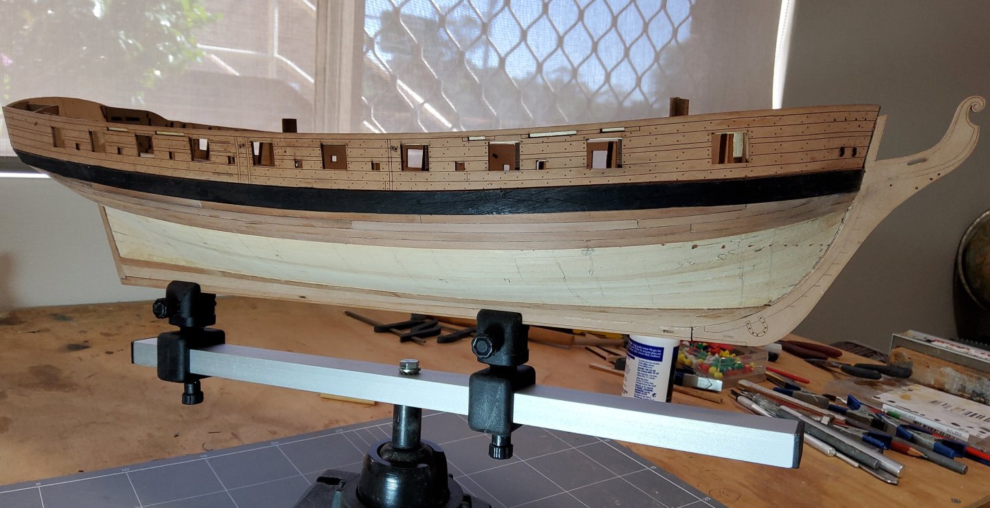
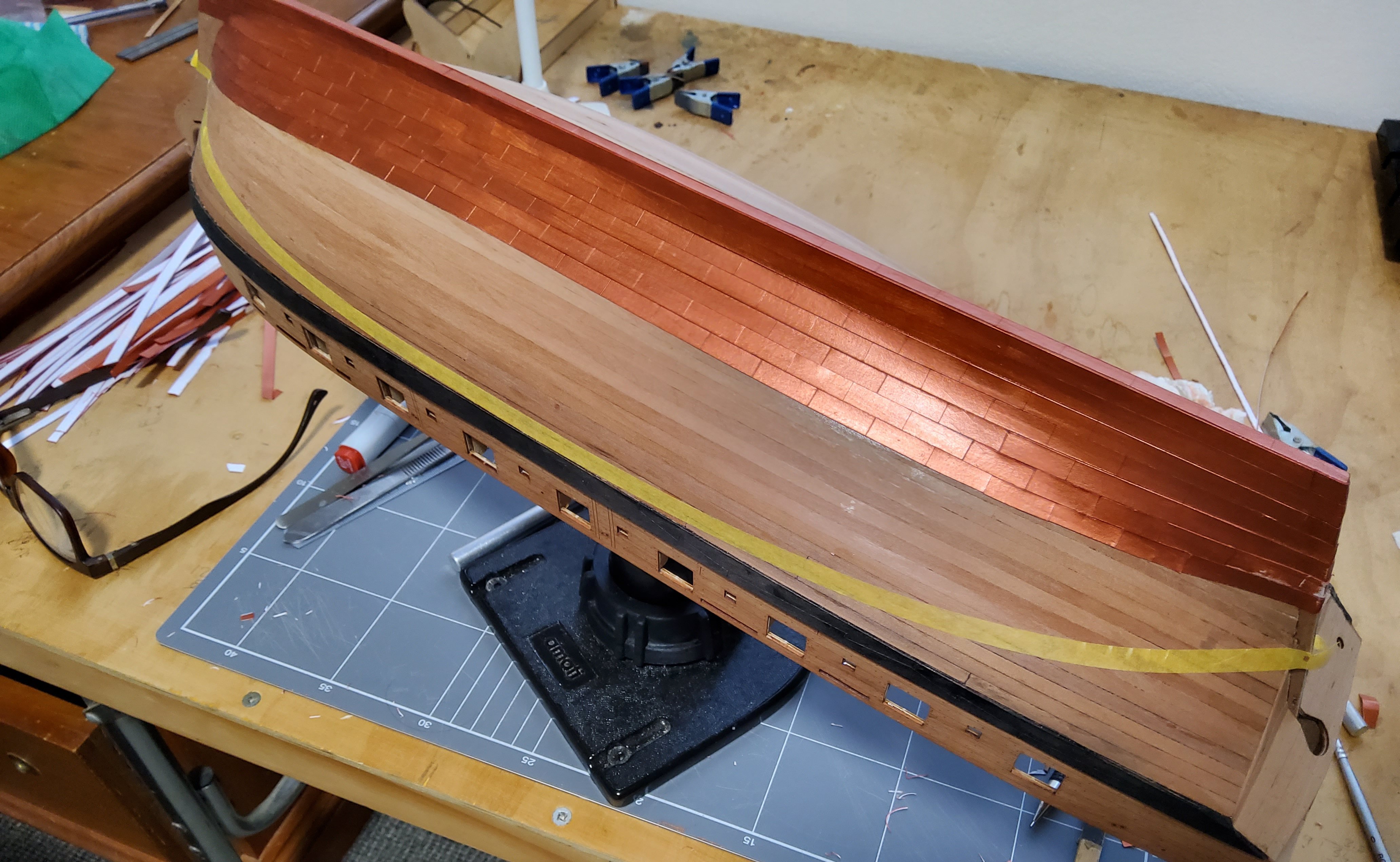
So, on to coppering. My kit came with the copper tape, not the copper plates, and as I have never used tape before, a learning curve will be inevitable. I first gave the hull a coat of poly so as to give the adhesive-backed tape a good smooth surface to adhere to. As the instructions advised, separating the copper from the backing can be tricky, if curling and creasing of the former is to be avoided. With care I managed to get two full runs of continuous copper plates, one against the keel and the other along the garboard strake. I wasn't happy with the result as there was some creasing of the copper, and it being so thin, it showed up every imperfection on the hull. I made a couple of attempts with single plates, but these weren't especially good. What to do - persevere and hope with practice that the results would improve, but this of course would mean keeping the poor results in place or removing these and starting again. After playing around with further attempts on scrap wood, I decided that I was unlikely to get a satisfactory result by using the copper tape. So, I removed the two runs I had done, cleaned the hull where these had adhered and decided to use a method I had used on my Bellona build. This involved painting several sheets of paper with copper paint, stripping the paper so as to give continuous runs of plates and then gluing these on the hull. Once the paint was dry, I marked the short edges of the sheets with tick marks 6mm apart (the width of the supplied tape) and marked the long edges with tick marks 18mm apart (the suggested length of the plates). The sheets were scored across the sheet every 18mm. I used a rotary cutter and pressed lightly, The sheets were then cut every 6mm to give strips scored every 18mm. To avoid any appearance of white paper edges, those were coloured with a felt-tipped pen. The prepared strips are shown in the photo below. Coppering of the hull then commenced, starting at the bottom of the stern post and working forwards and upwards. Where possible, continuous strips were used, reverting to single plates when necessary. And before anybody asks the bleedingly obvious question - why didn't I just cut the paper into scored strips then paint them once glued to the hull, it would have been much quicker - I have no idea why I didn't think of it.🥴 🥴. Cheers

-
A big decision Glenn , and well done. I may be making a similar decision myself soon.
- 241 replies
-
- 2
-

-

-
- Vanguarrd Models
- Harpy
- (and 1 more)
-
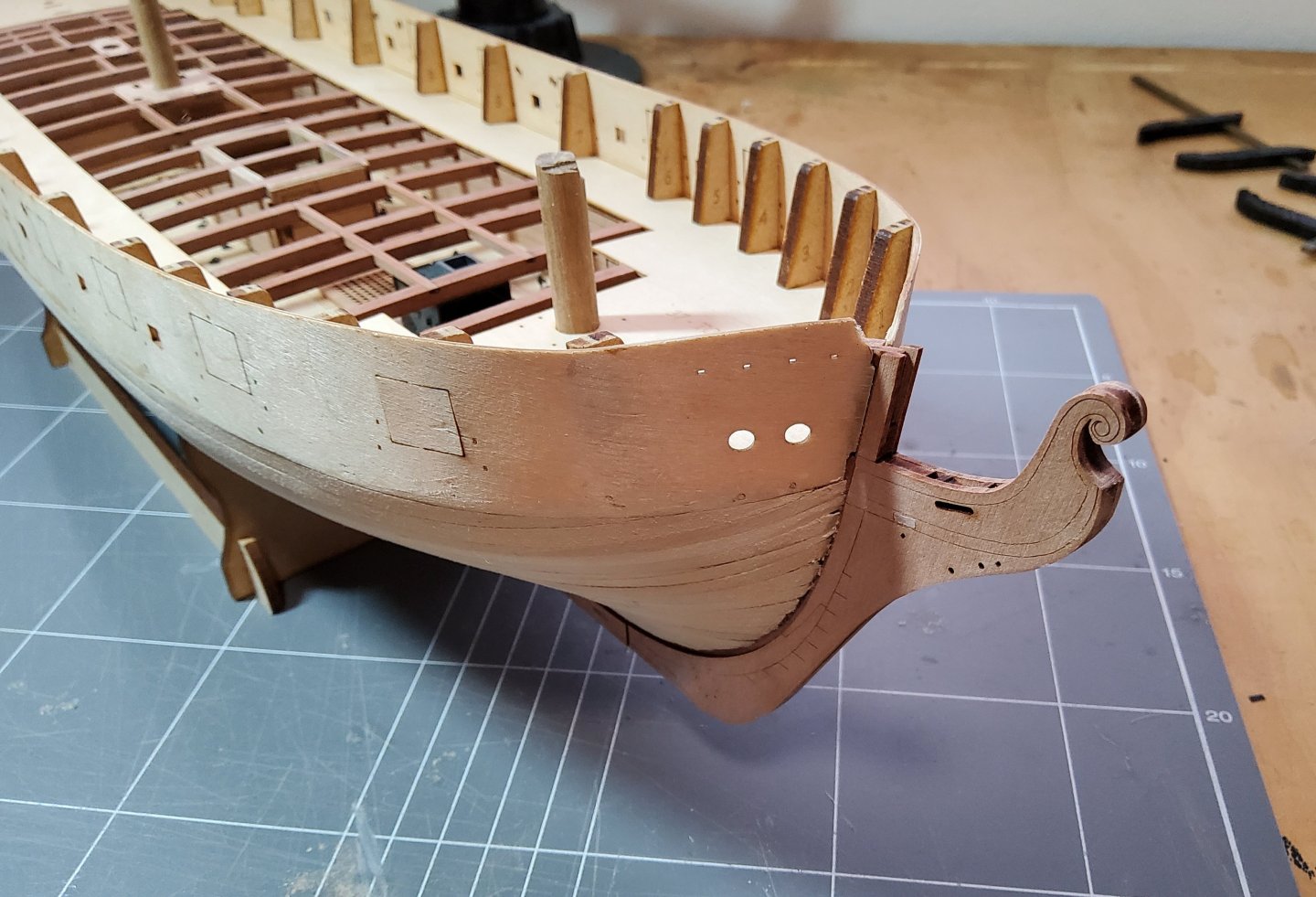
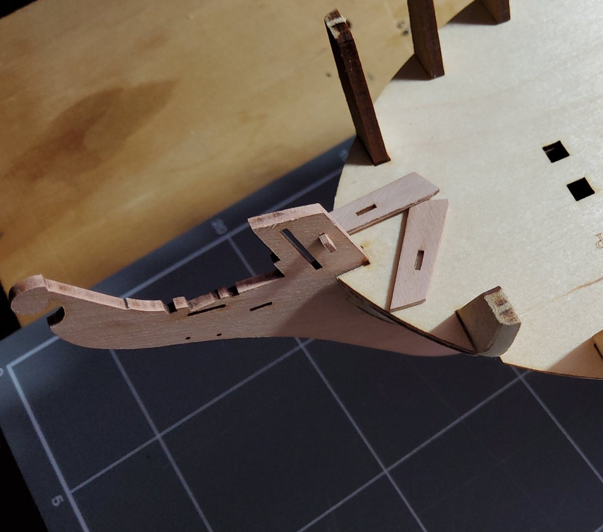
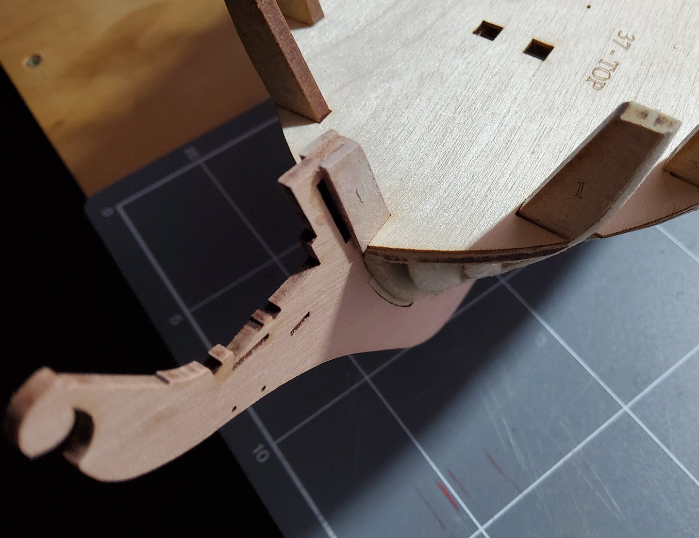
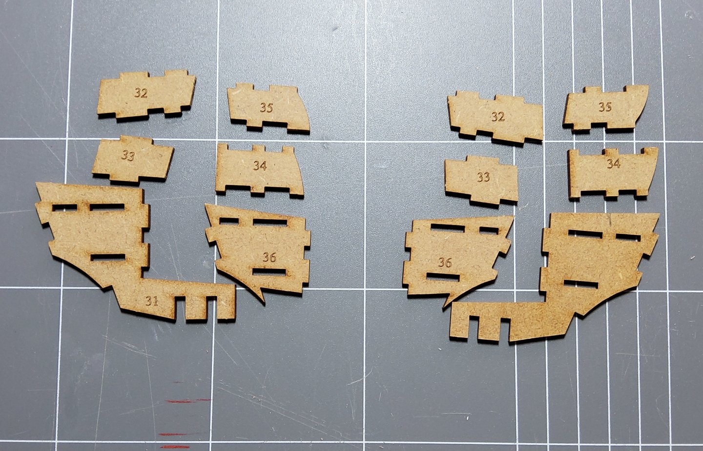
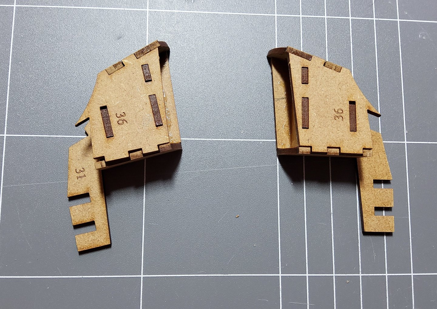
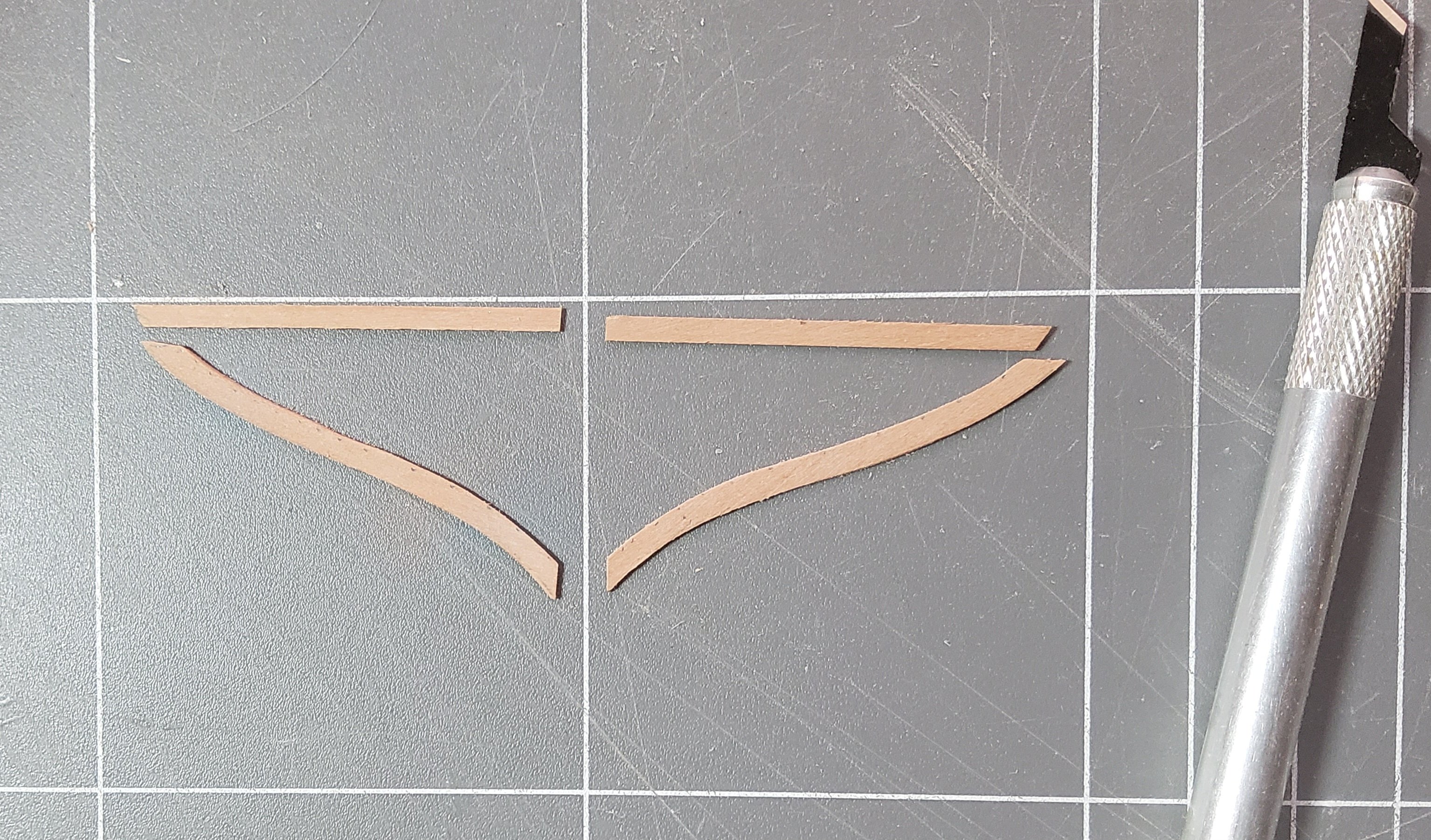
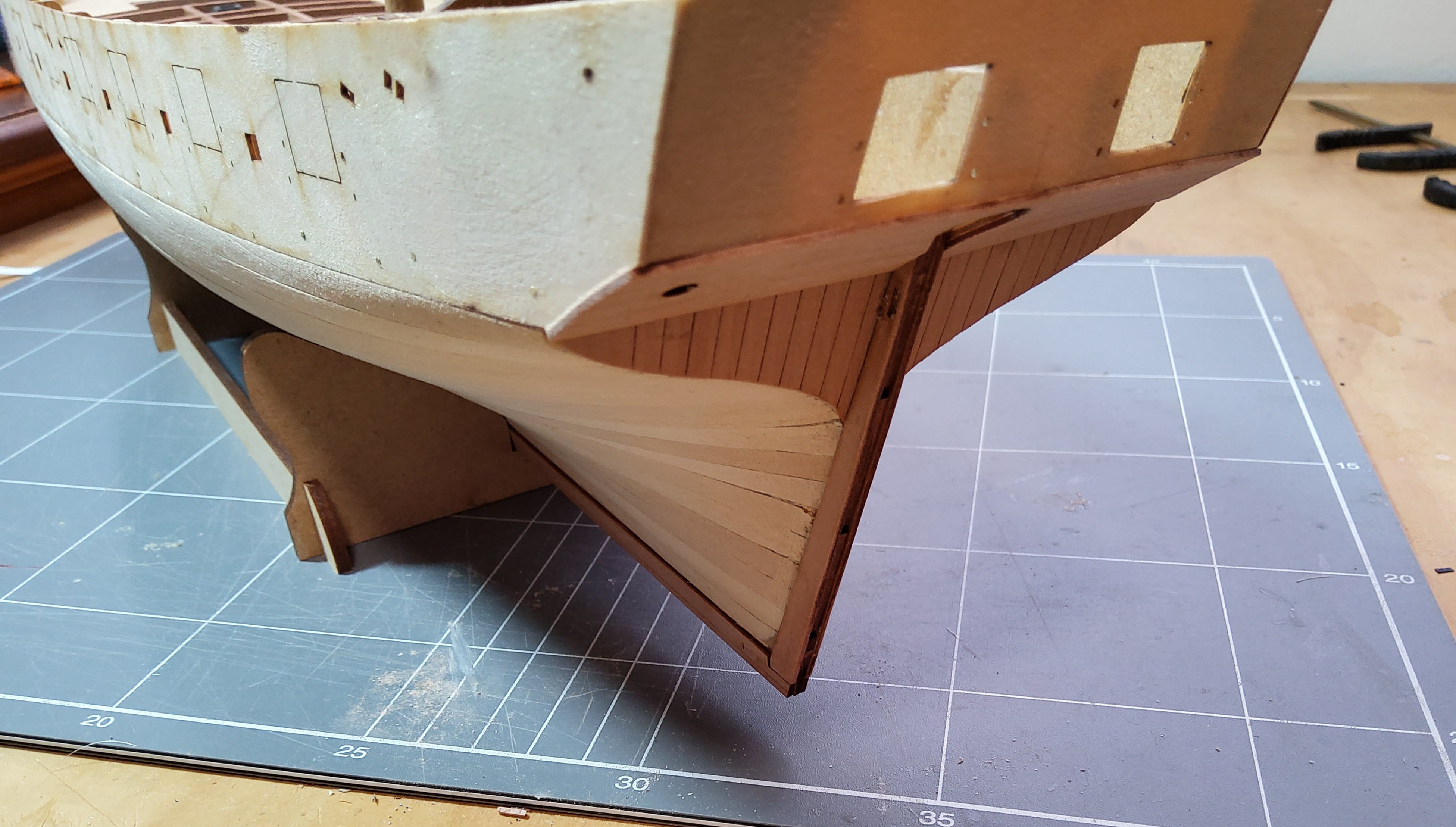
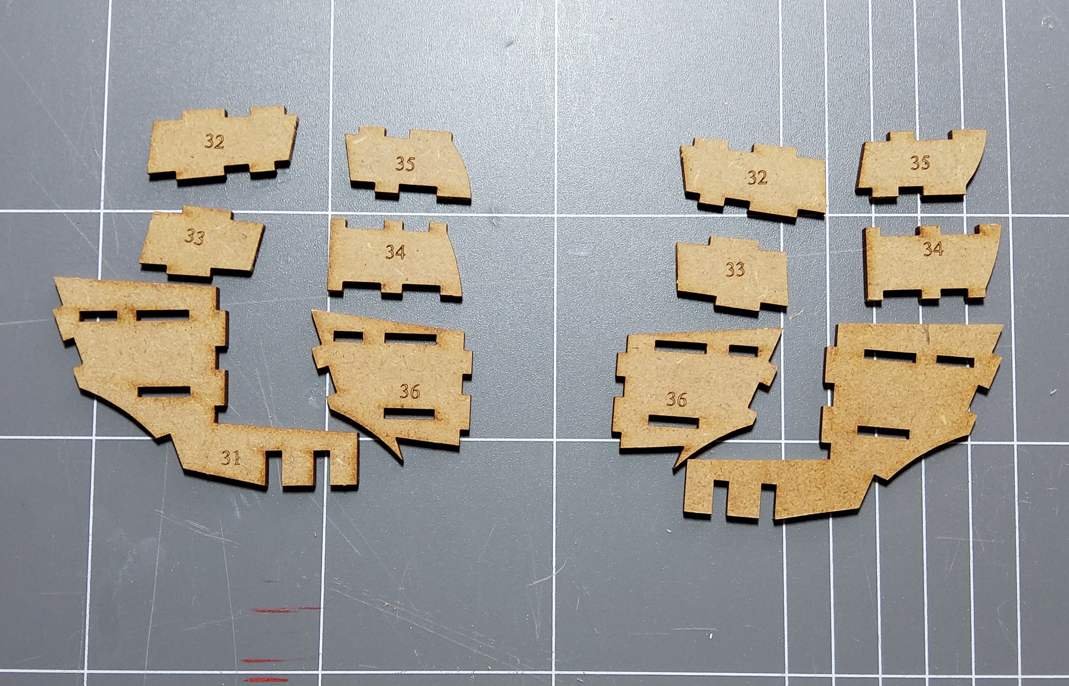
OK, I've been away on a holiday for the past four weeks, so very little has been done since the last post. I decided to do what others have done and put a frame around the stern square tuck, though I did it in a different way to the other builds. Those formed the frame then infilled it with new planks over the existing kit-supplied stern piece with the frame thus being flush with the new planks. I thought of a simpler method - though in reality it probably wasn't. The photo shows the four pieces for the frame. These were cut from 0.6mm pear fret. One of the curved pieces had to be redone as dry fitting showed it to be somewhat off. The pieces were then very carefully sanded so that the inside edges came to a knife-edge. That is, they finished with a triangular cross section. They were dry fitted, then glued in place. From a normal viewing distance it is very difficult to see that the frame is actually sitting on top of the planks. Cheers


-
OK you two, now you've got me involved as well 😁😁😖. Just ordered the kit plus canopy plus laser cut pieces. I may be slow as I'm part way through building Harpy. Cheers.
-
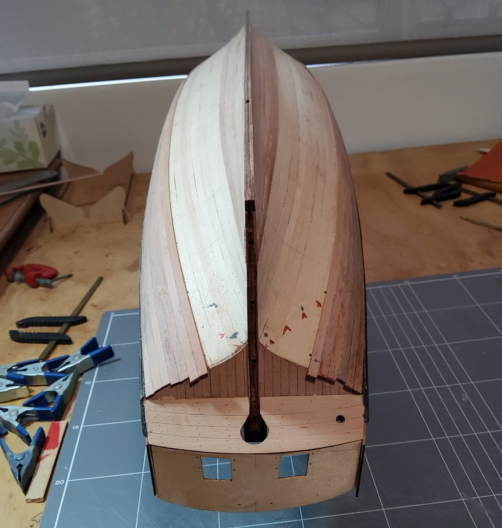
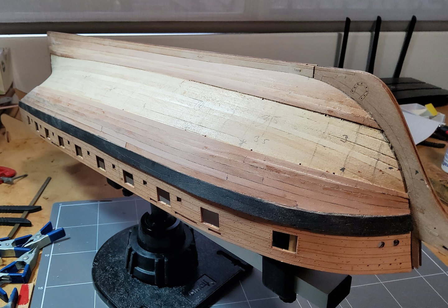
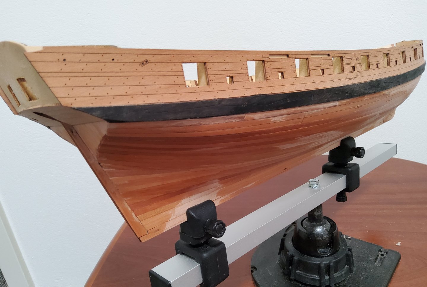
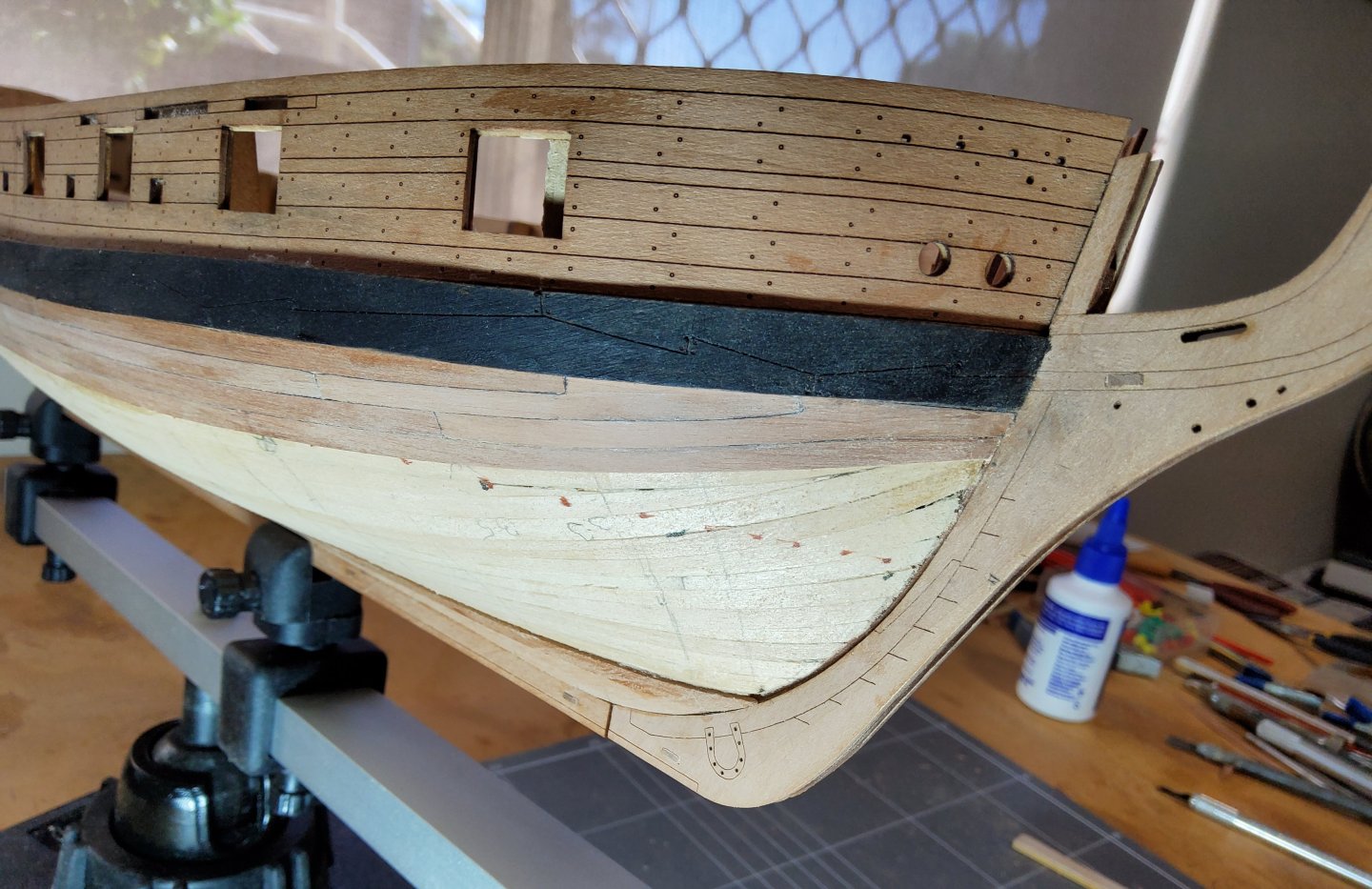
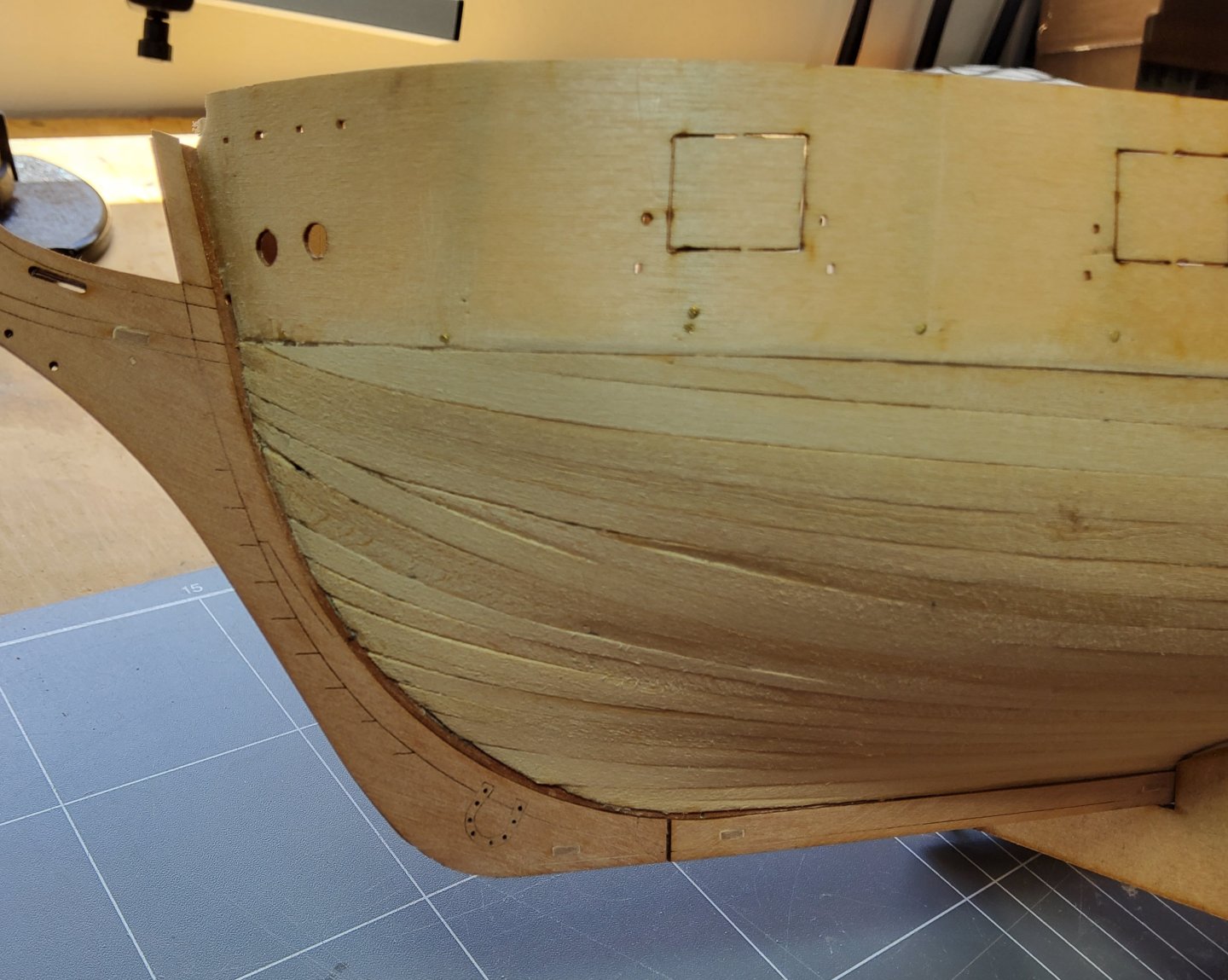
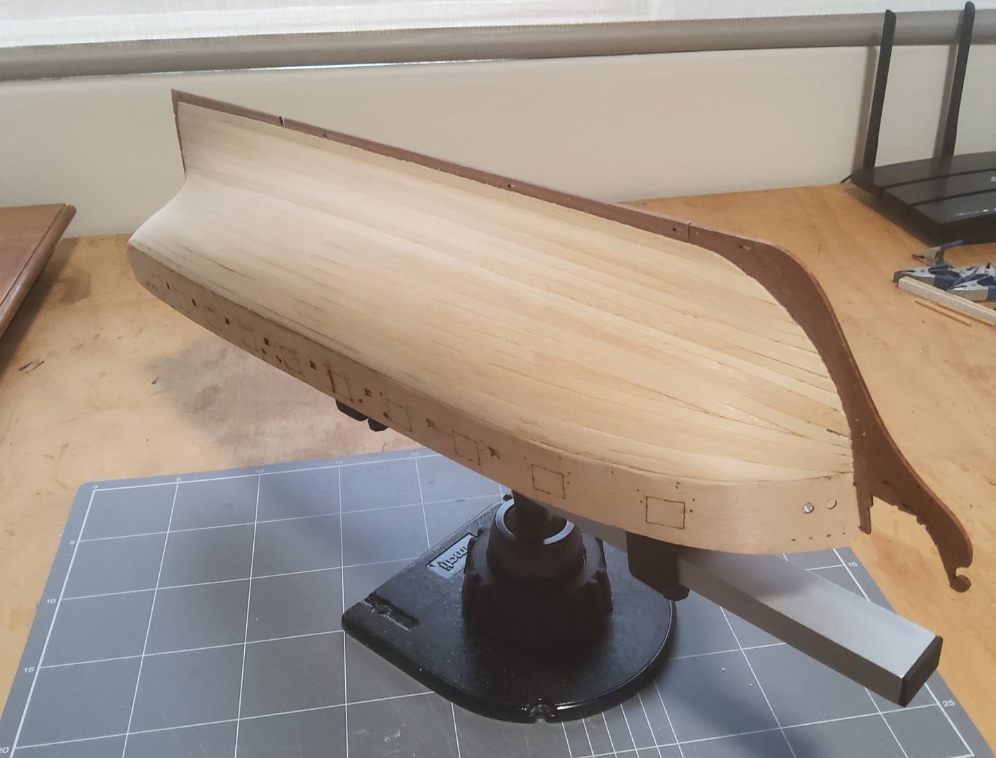
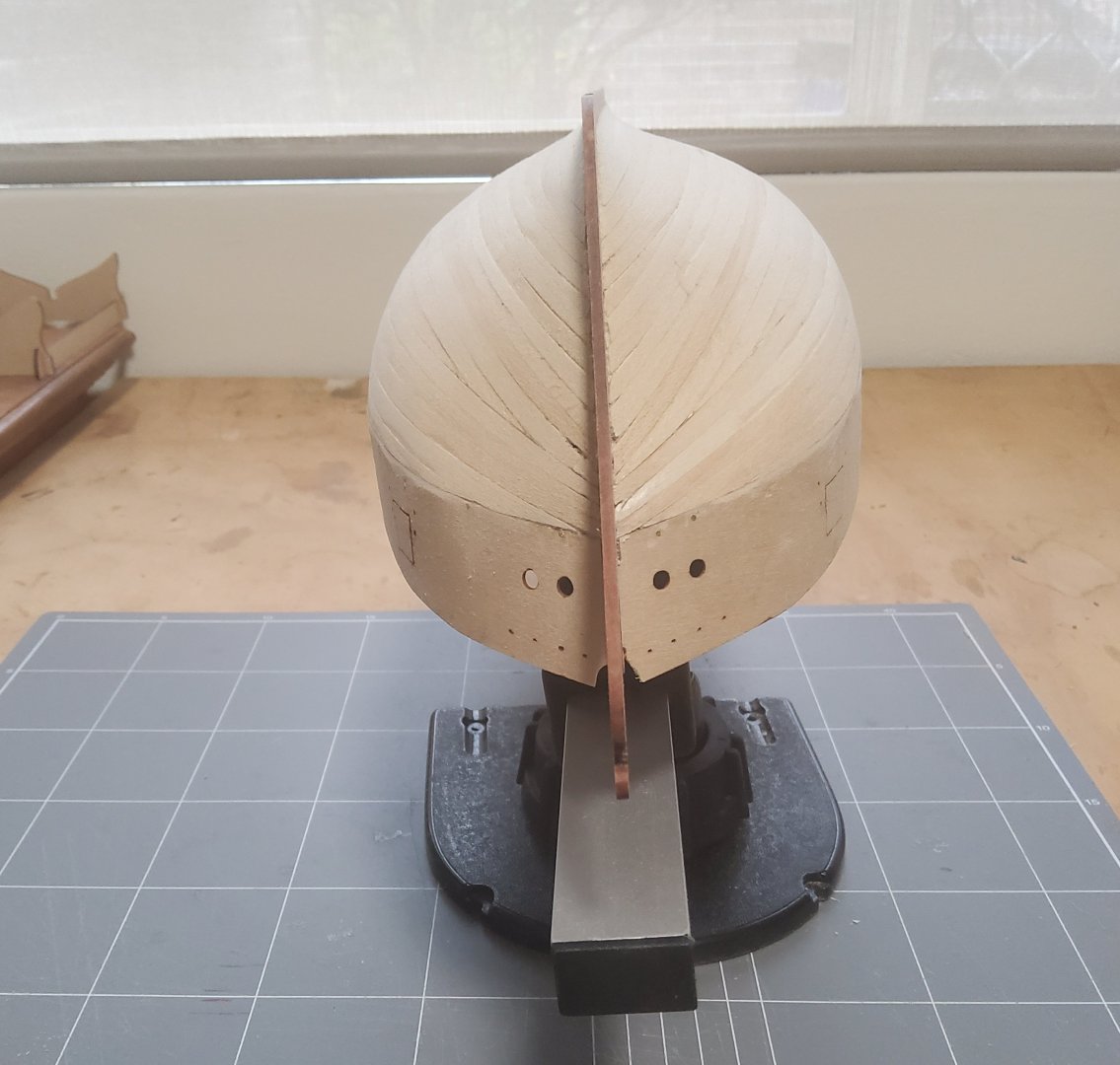
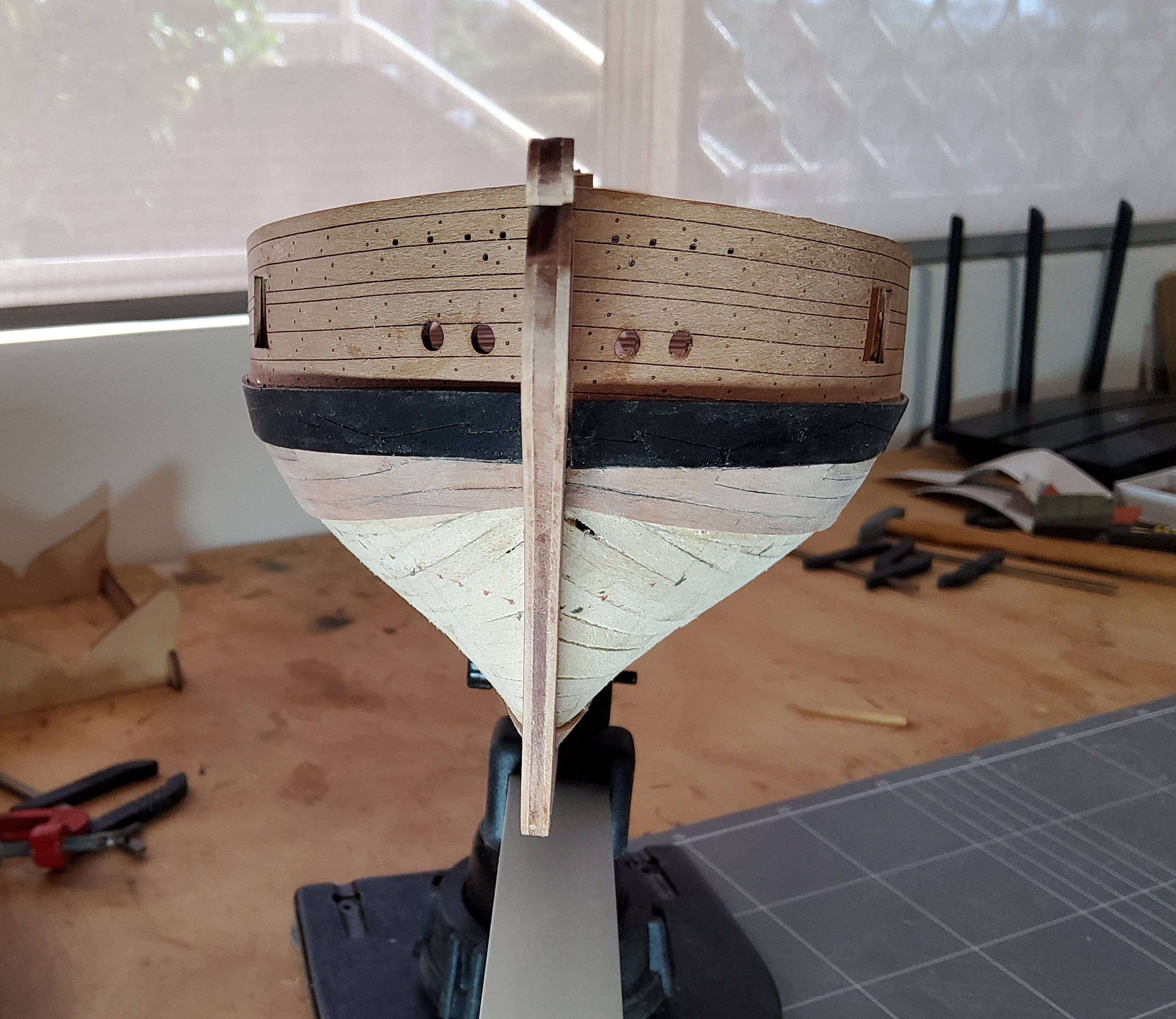
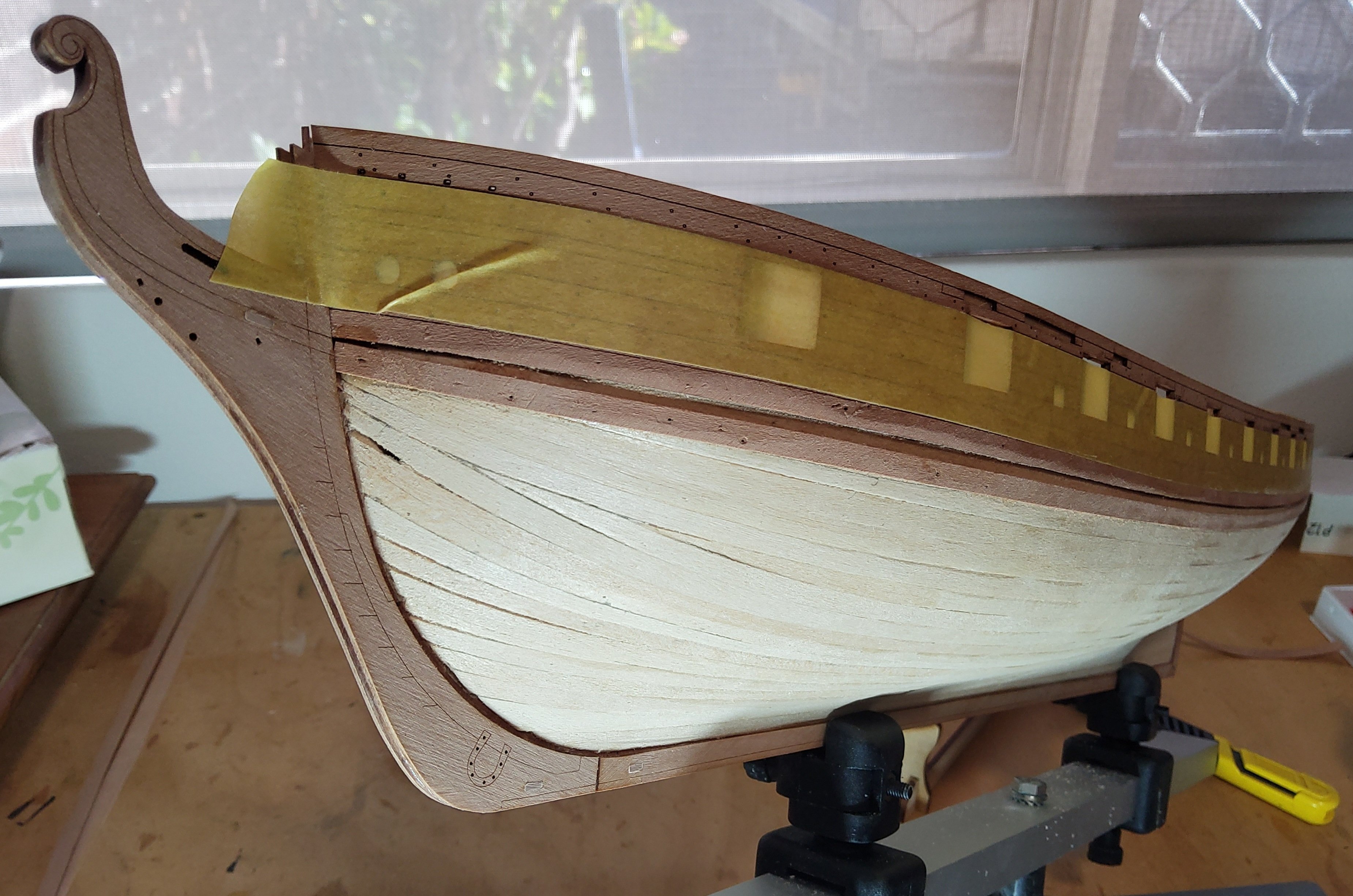
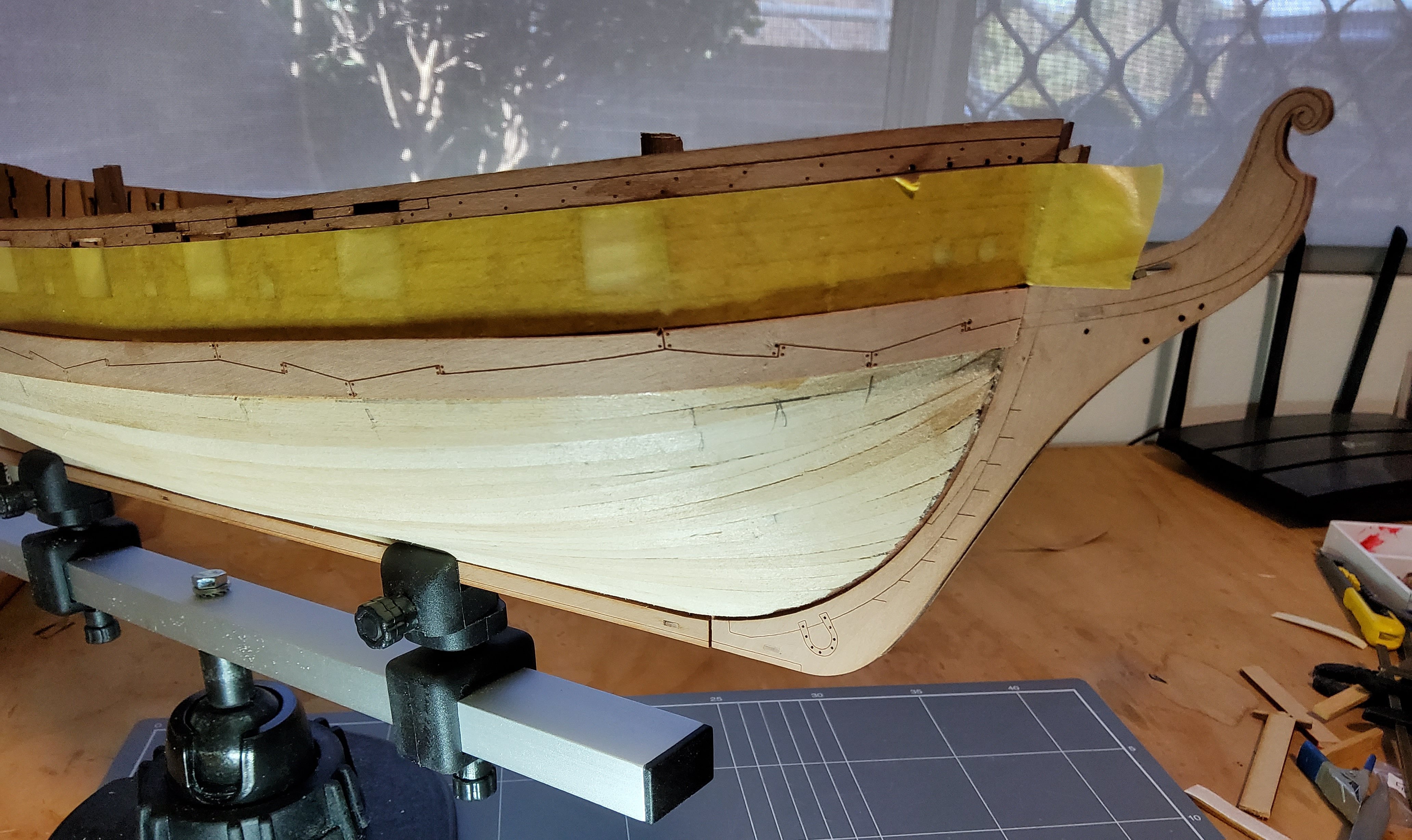
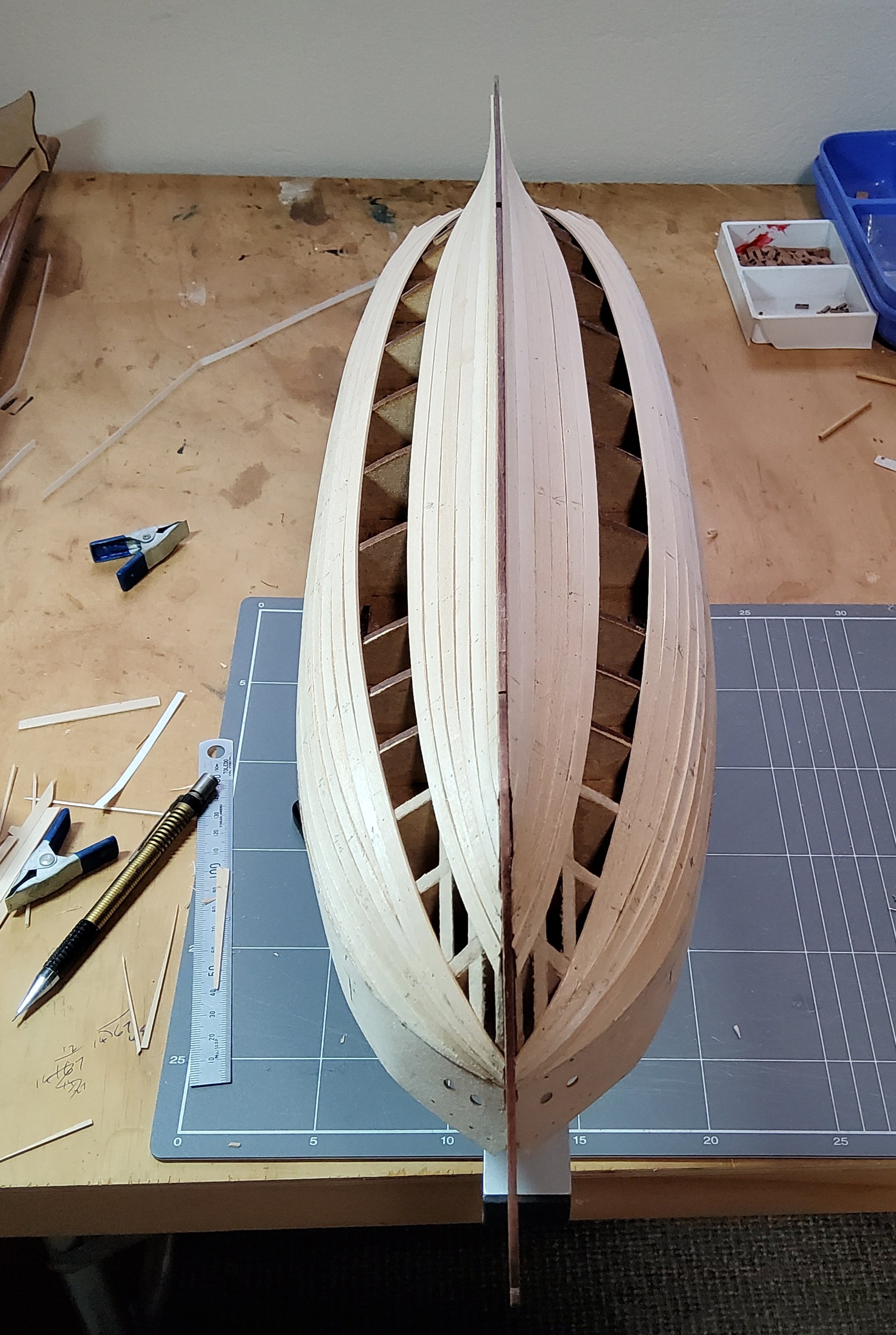
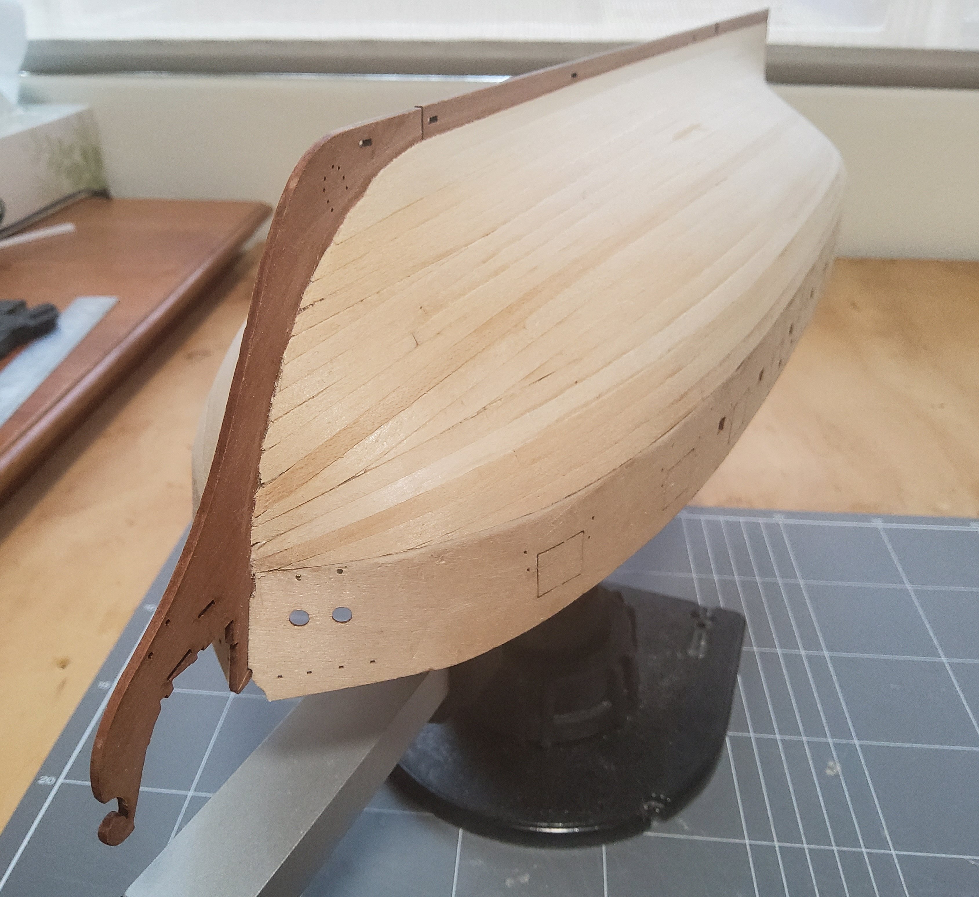
After a break, slow progress with the second planking. The following three photos show the beginning with several strakes in place. A wider strip cut from pear fret was used as the garbord strake, and planking continued upwards from this and downwards from the wales. The usual methods of planking were used, tick marks, tapering and edge bending. I had already fixed two drop planks in place at the bow, then needed two stealers ar the stern. I didn't make much of an attempt to colour match the planks as most will be covered by copper. Some of the supplied pear planks were unusable full length due to ragged edges. Finally, the planking was completed. The hull was hand sanded, finishing with 320 grit. The hull in the following photos was wiped with a damp cloth for the photos. The hull still needs a little attention before coppering takes place. I am happy enough with the way the planking turned out. Cheers


-
Thanks for your detailed build log Glenn. Your descriptions of the problems and possible solutions will be very handy when I reach that stage in my build. Cheers.
- 241 replies
-
- 1
-
-
- Vanguarrd Models
- Harpy
- (and 1 more)
-
Wow, the speed of your progress is amazing. I'm only up to the second planking and I've not done much of that. Well done.
- 73 replies
-
- 1
-
-
- Harpy
- Vanguard Models
- (and 1 more)
-
Thanks Maurice.
-
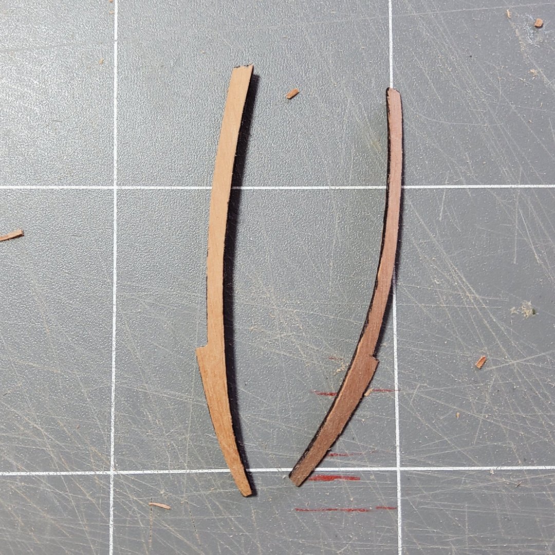
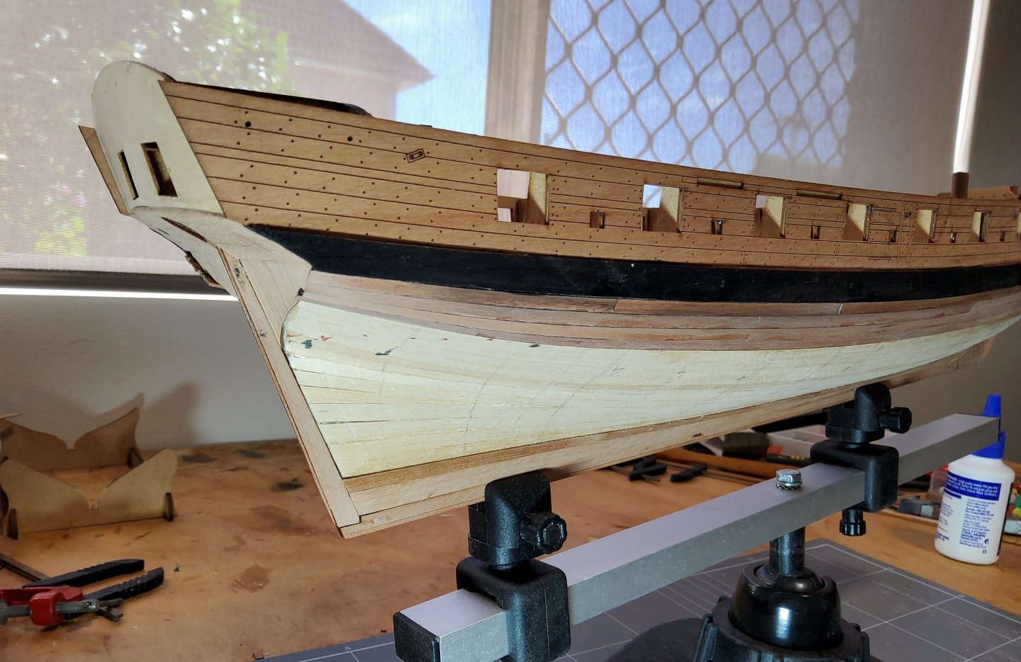
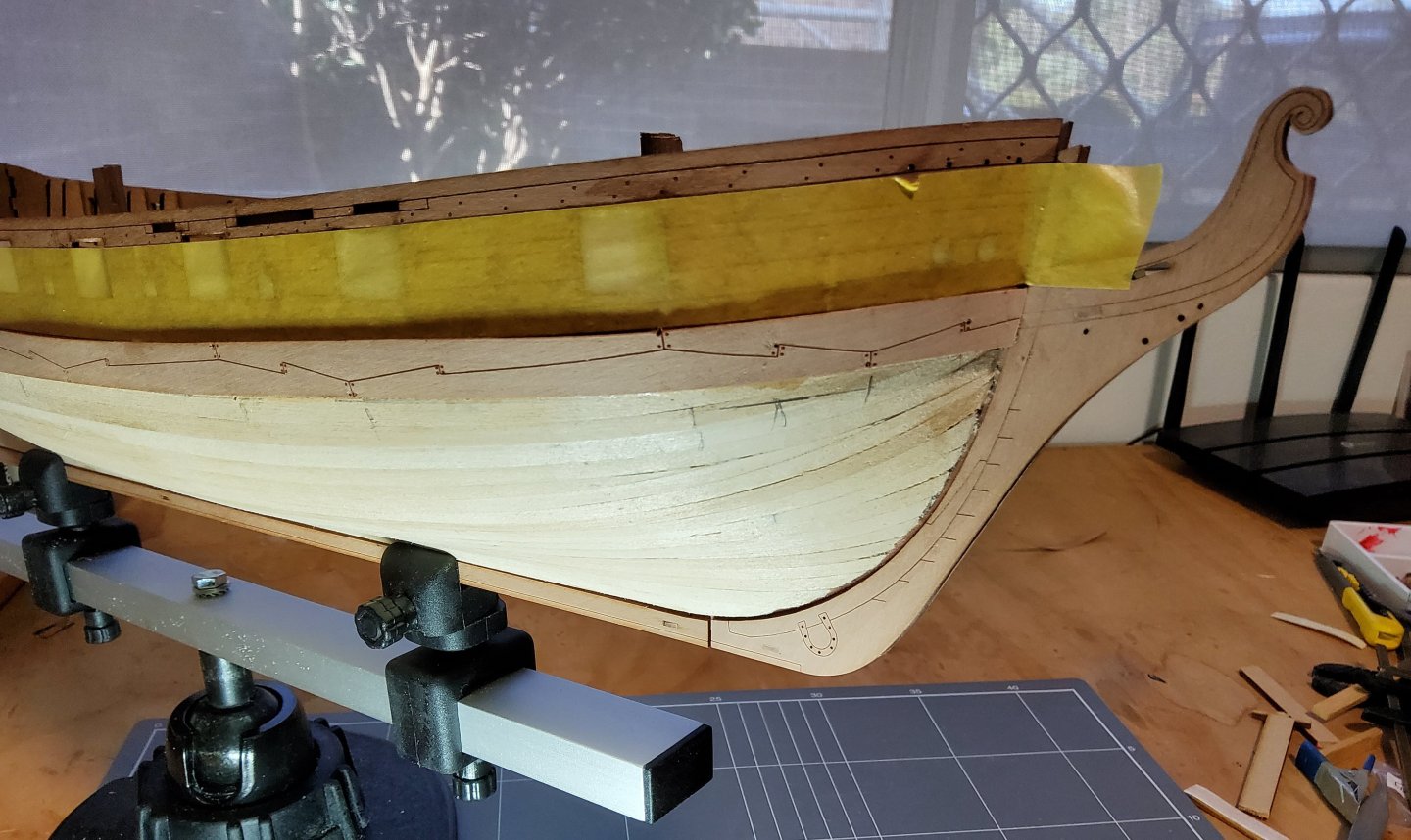
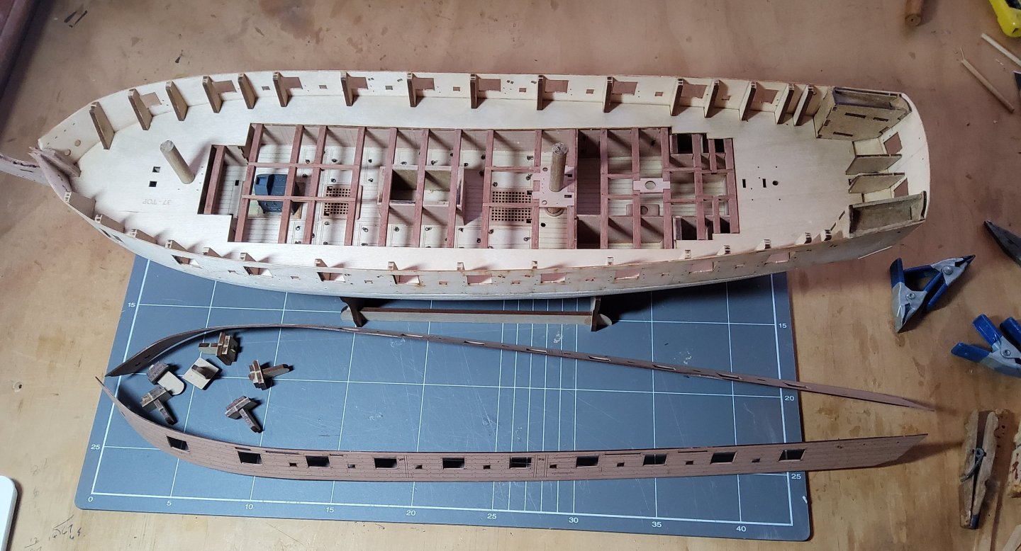
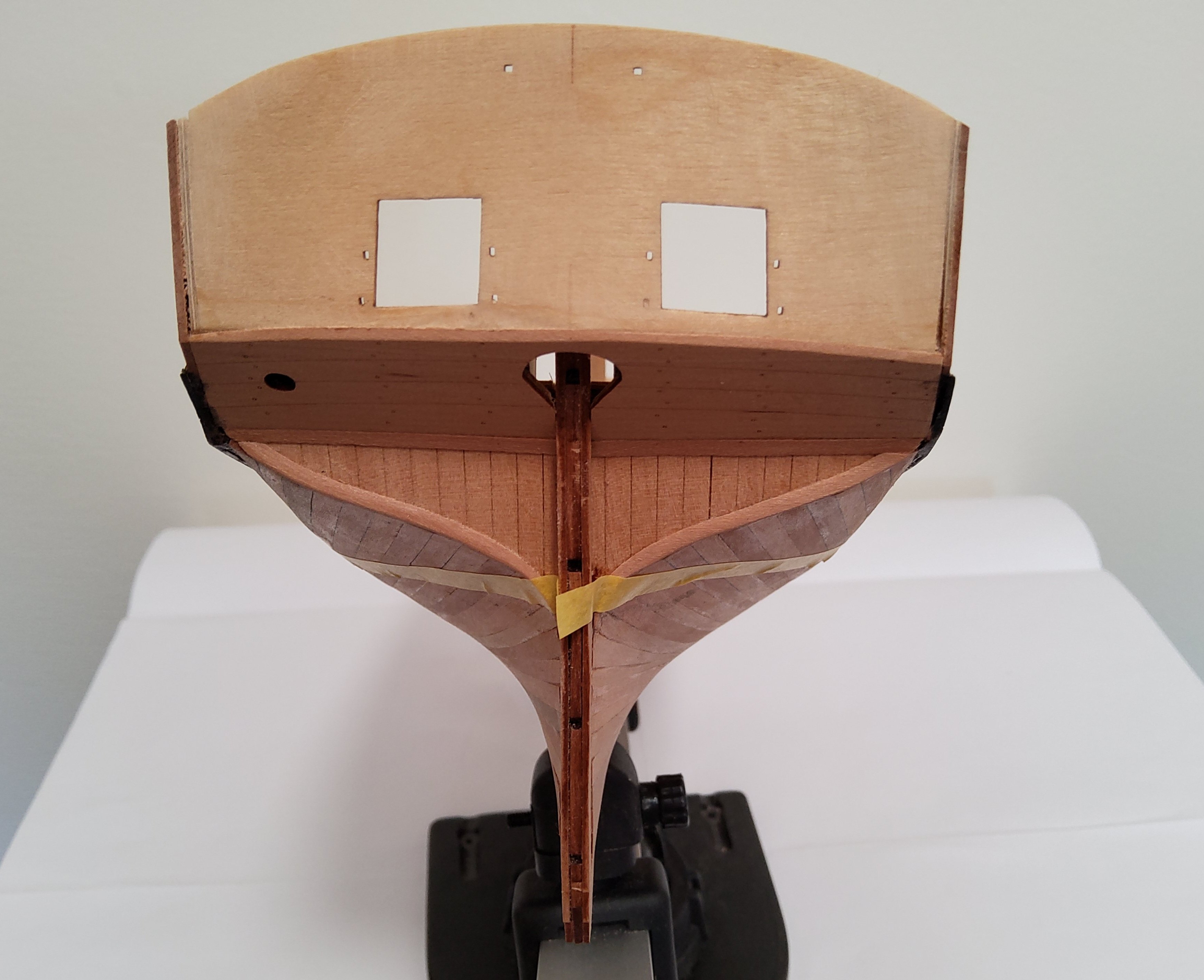
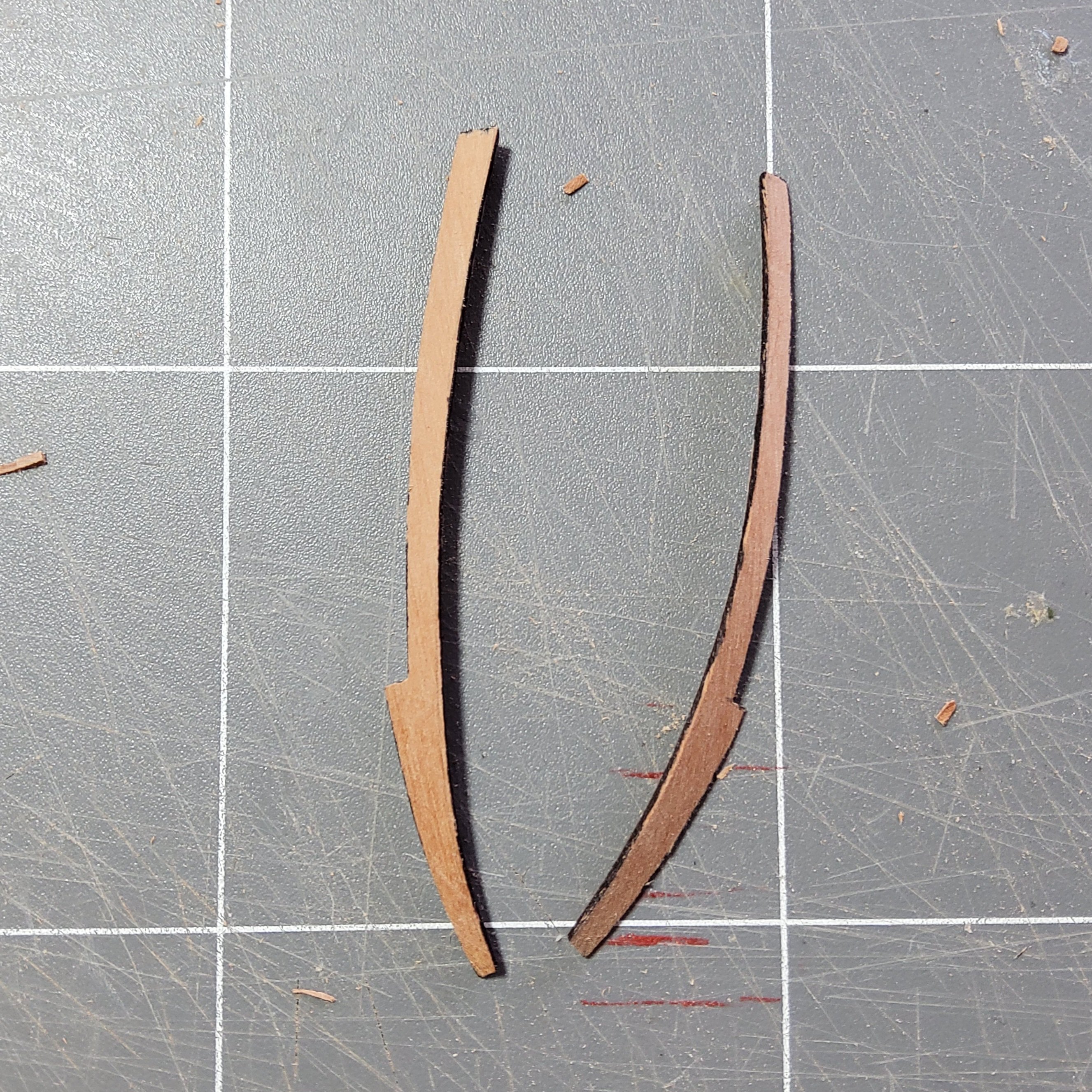
After a short break, I'm now about to start the second planking. The wales were first coloured black, using an artist's felt-tipped pen. This is a dye, not paint, so is only good on bare wood. Mostly I intend to run uninterrupted planks from bow to stern, but where the strakes are above the waterline, I will use scale-length planks. I will take the length of these from the size of the individual planks that make up the wales, as these would have certainly ended on a frame which would not necessarily coincide with the model's bulkheads. Other Harpy builds have simply edge-bent the planks at the bow, but I decided to use a drop plank in each of the first two pairs of strakes, ie four strakes midships reduced to two at the stem. The first strake under the wale was run from the stern and stopped short (after tapering) at about bulkhead one. The next strake ( number 2) would be the one that has the actual drop plank, so to get this in the correct position it was run from the stern to about bulkhead three. The third strake was then run full length thus leaving a gap between the wale and strake three, which would be filled with the short drop plank. This process was repeated to fit the second drop plank. Making the actual drop planks took quite some time with much trimming and dry-fitting. One of the four needed two attempts as the first ended up about 2mm short. These planks were cut from spare pear fret, using a template to get the rough shape. The template was formed by laying a length of masking tape over the gap and running a pen along the edges. Sorry guys, this sounds complicated and I forgot to take photos which would have helped. There is a clearer description with photos in B.E.’s Harpy build log (Post 21). Two of the four drop planks. The hull ready for the rest of the second planking. Cheers

-
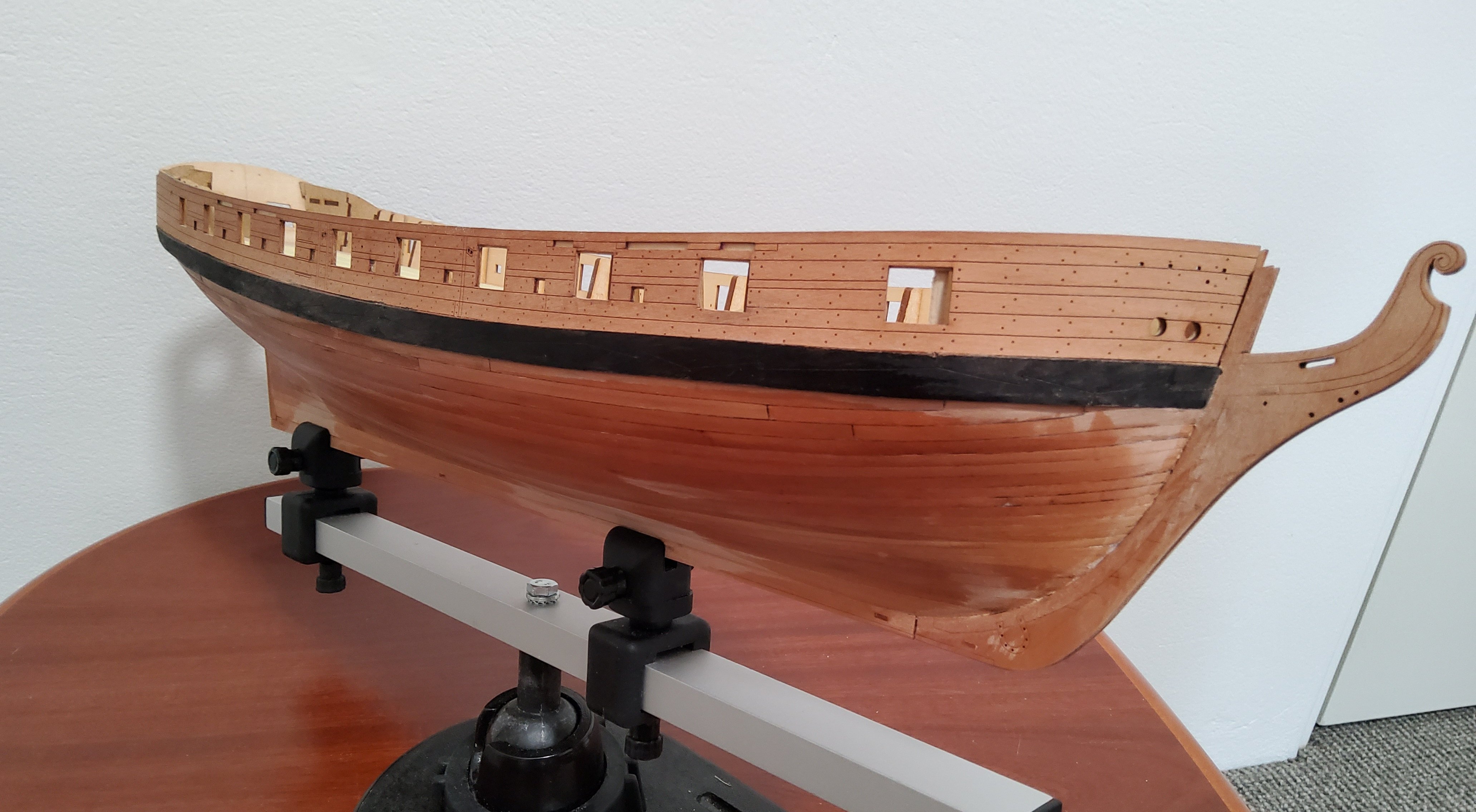
A short post to explain what I did for the wales. Following B.E.’s example, I decide to fix the wales in place before doing the second planking. However, I did not do what B.E. did, which was to install two strakes below the bulwark pattern, then glue the wales ontop, finally trimming the lower strake so that it did not protrude below the wale. Then on to the second planking proper. Instead, I taped the wales in position, then ran a pencil below the wales to mark their lower edge, then I glued a single strake along this line as shown in this photo. The wales were then glued in place, the top along the etched line on the bulwark pattern, the bottom sitting neatly along the installed strake. The dark line above the wales is a shadow, not paint. Cheers


-
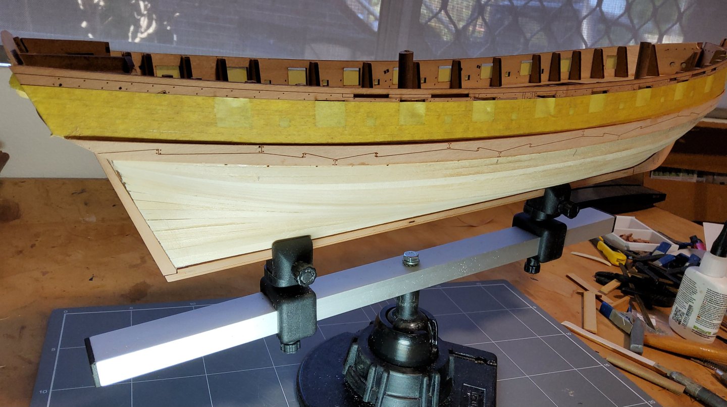
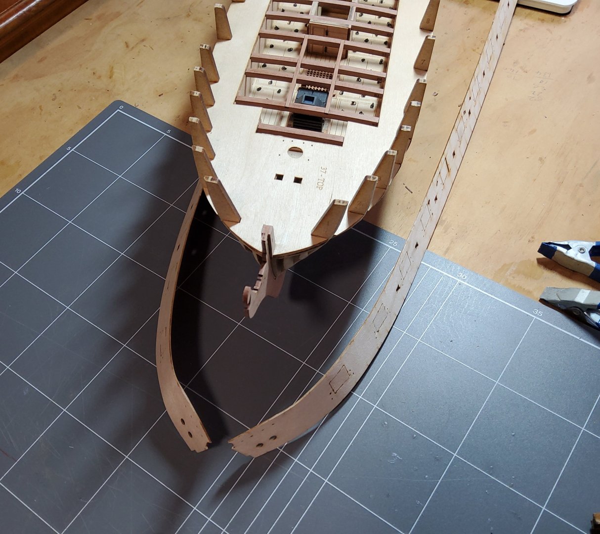
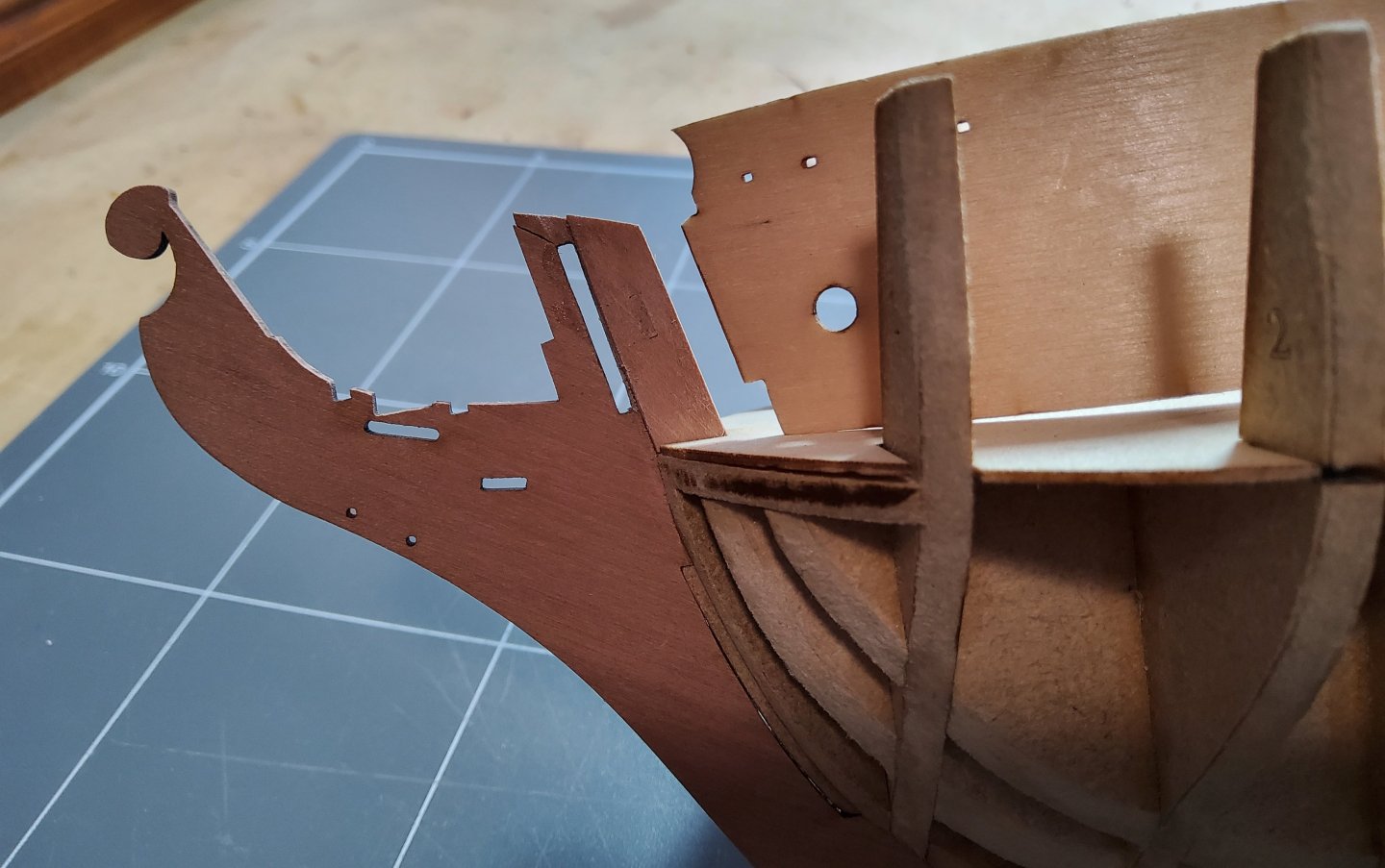
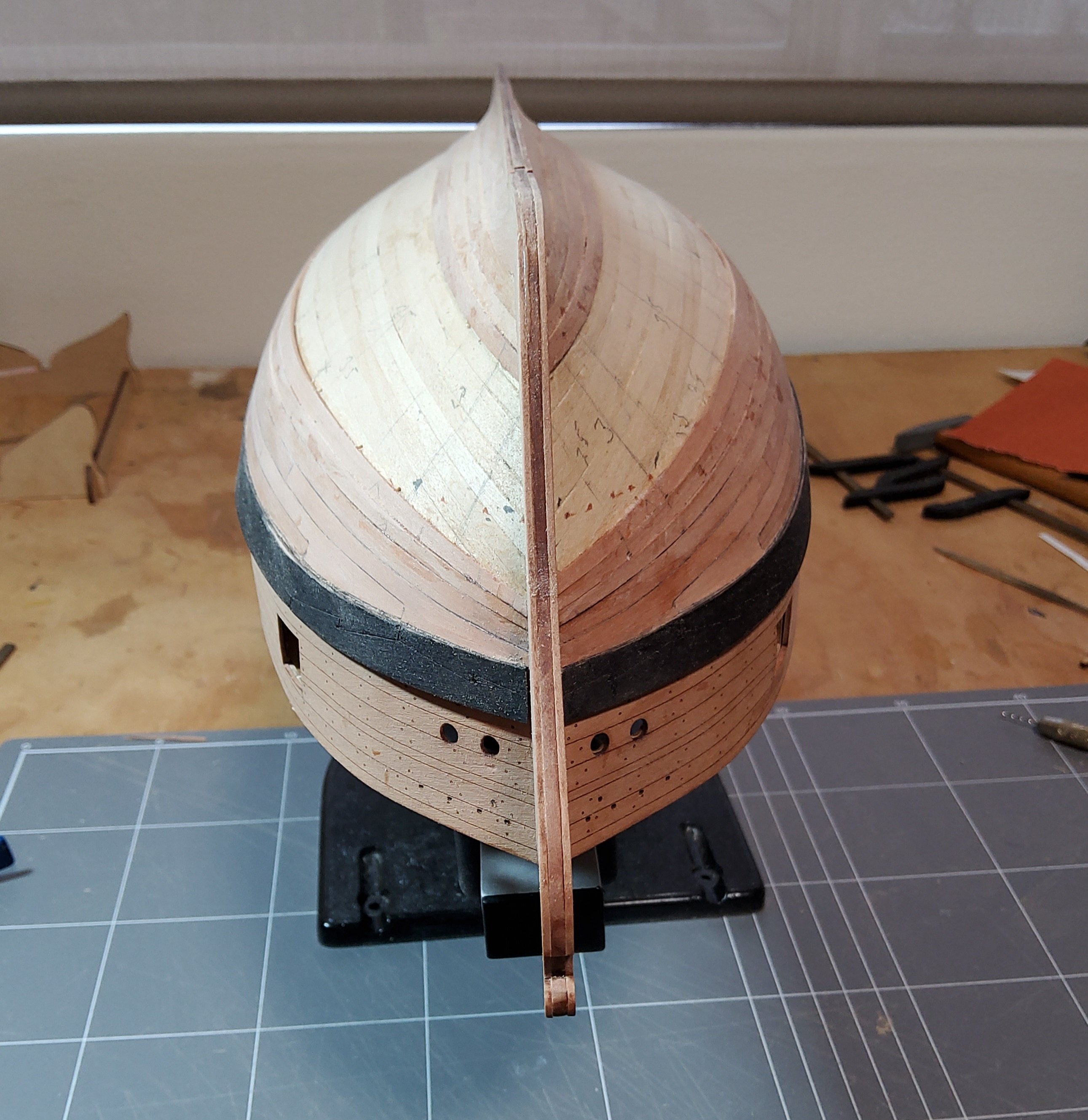
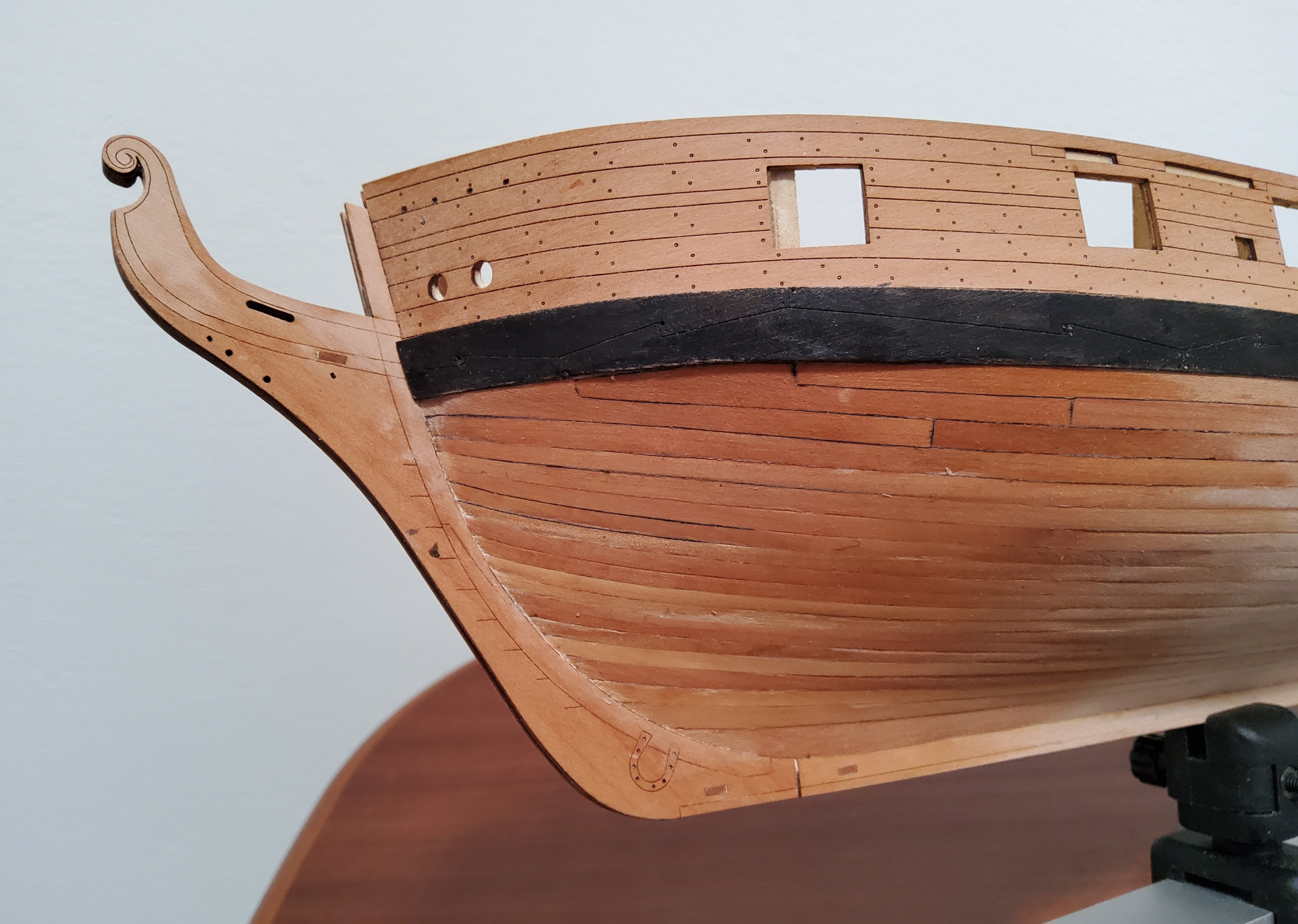
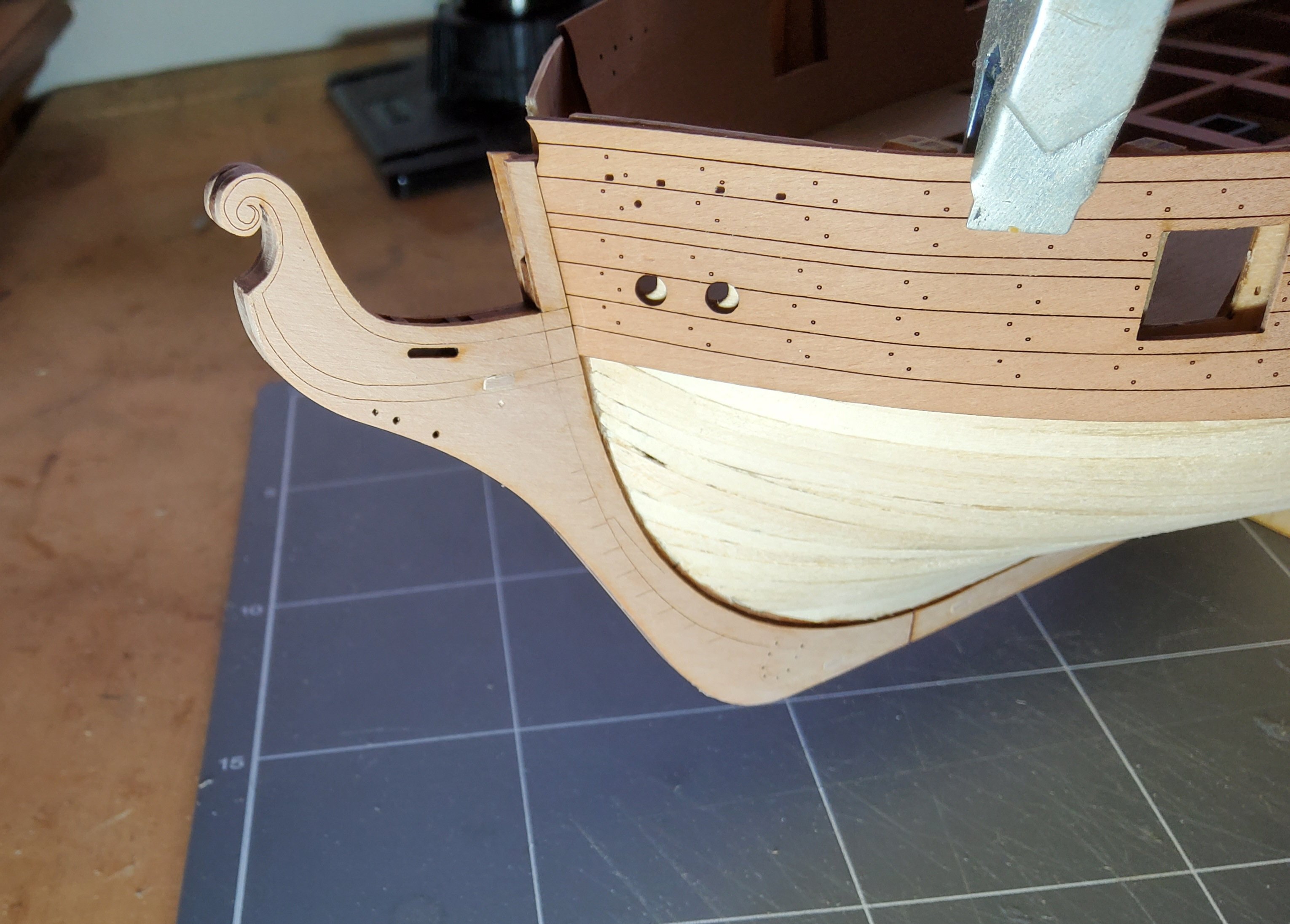
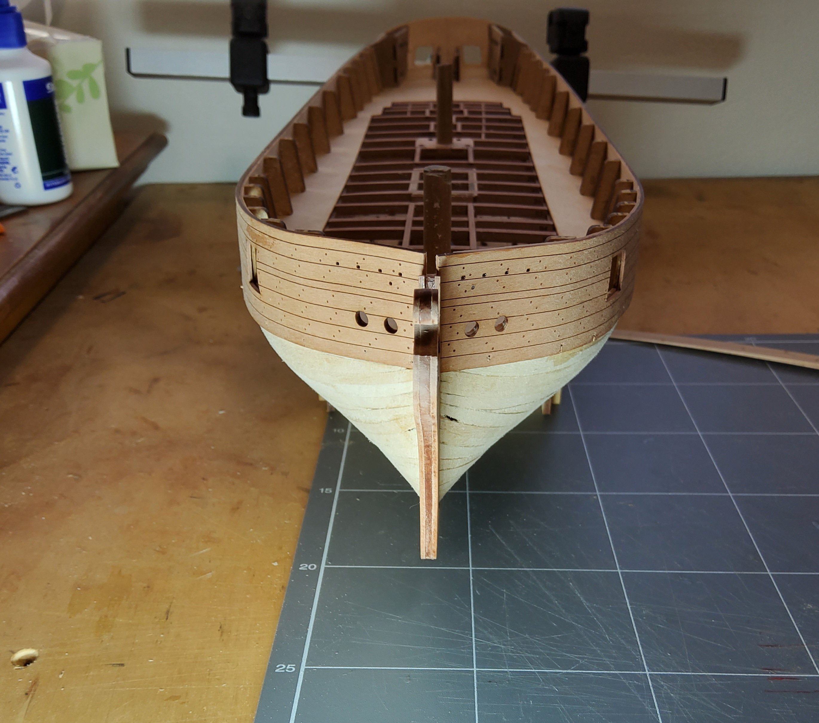
Thanks for all the likes and to those who have dropped by. Following the planking, the veneer facings on the stem, keel and rudder post were added. There is a definite gap between the end of the planks at the stem and the veneer. This will act as a very useful rabbet when the second planking is done as the ends of those planks will slot neatly into it. Next up, the outer bulwark patterns. These were soaked for a short period, then clamped to the hull and allowed to dry - helped along by a heat gun. The two patterns after drying and some of the gunport jigs that will be used to ensure correct alignment. A problem arose when I dry-fitted the bulwarks. Jigs 6,8, and 10 were used and slotted in easily to the outer bulwark pattern and the inner ply gunport pattern. But the bulwarks are too long. At the stern this was expected as the instructions mention this. However, they are also too long at the bow, and this photo shows the misalignment of the inner and outer sets of hawse holes. Trimming of 1.5mm from the front of the patterns fixed this. The bulwarks were then glued in place, still using the three gunport jigs to ensure correct alignment. The port one has been done and that on the starboard side has been glued up and clamped to the hull. Pins were used along the lower edge and later removed. Next up will be the second planking, but before I start this I need to decide on how the wales are to be added. The instructions call for the planking to be completed, then glue the wales on top. As B.E. has pointed out, this will result in a visual difference between the run of the wales and the run of the planks, though the difference would not be great. I am tempted to follow B.E.’s solution and put down a run or two of planks, trimmed appropriately, with the wales fixed on top, then the planking commencing below, butting up neatly against the wales. I also need to decide whether to use scale length planks above the waterline, below won't matter as this will be coppered. Cheers


-
Post deleted - should have read ECK's post more closely 🤒.
-
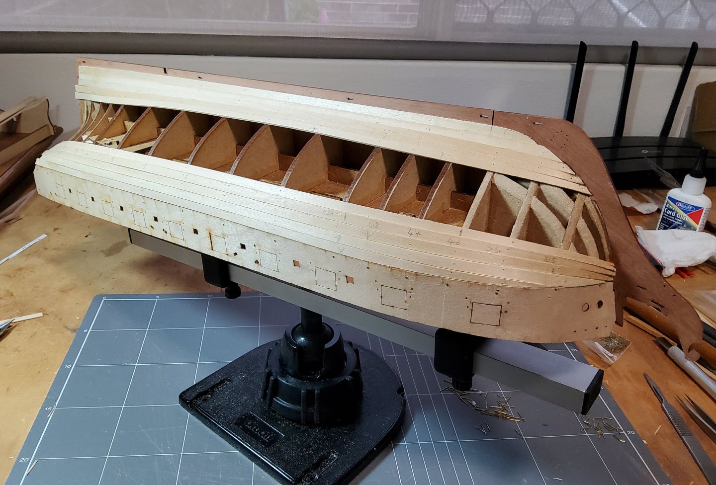
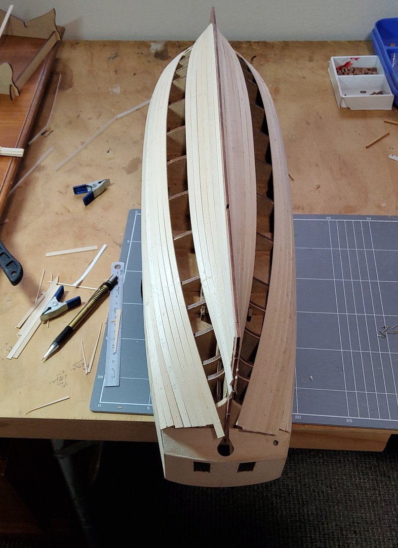
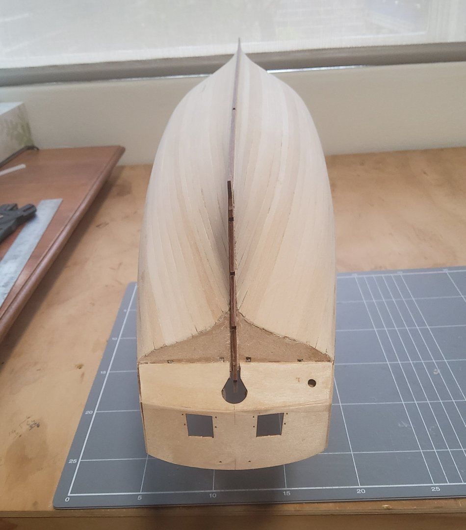
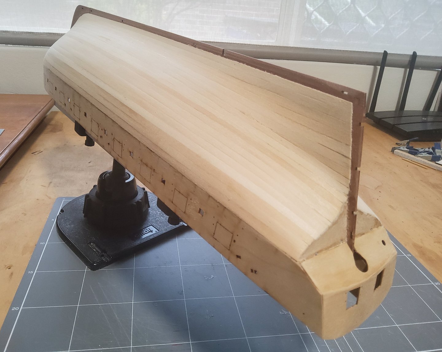
Planking of the first layer is complete. It took a while and I'm happy with the way it has turned out, although it's not quite the standard necessary for a single layer. I fitted the planks in pairs on each side, one strake at the top and one at the bottom, then re-measured the gap and adjusted the next plank widths to suit. As I didn't properly line the hull, I soon found that more drop planks would be required towards the bow than should have been necessary. Instead of correct drop planks I simply tapered the planks to fit. One stealer was needed at the stern. (Just as an aside, the limewood strips I have are slightly wider than 5mm - four of these side by side actually measure 21mm rather than 20mm, not much but it's cumulative.) The hull was sanded, firstly with 80 grit, then 120, and lastly a light going over with 180. Cheers


-
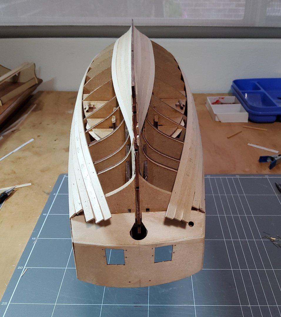
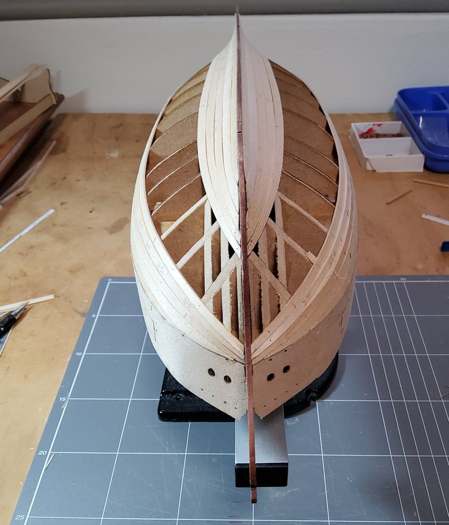
Just a short note today. Planking has started. I did the garboard strake first as this can be quite tricky, then added a second strake next to it. Two strakes under the ply gunport pattern completed the work for the time being. Next I will plank down and up. The distance, amidships, between the already installed planks, is equal to 14 of the supplied limewood strips. These will certainly have to be tapered towards the bow, but first inspection suggests a stealer may be required at the stern. I do know that real planks do not taper to a point, but as this is the first layer, I have taken the easy way and used pointy planks instead of making drop planks. Cheers


-
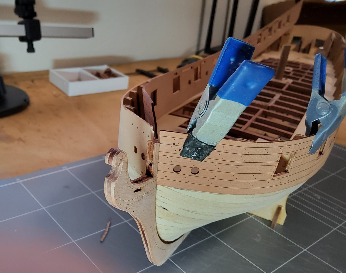
First off, thanks for all the likes and views, much appreciated. The fronts of the ply gunport patterns were soaked in warm water for a few minutes then the patterns were clamped in place on the hull. They were left to dry, helped by a heat gun, then glued into place, being careful not to get glue on the bulkhead tags, which will be removed soon. I had a problem though. The instructions call for the pattern front ends (ie the tabs) to be hooked into the prow. The photo shows the slot in the prow and the tab on one of the patterns. (You can also see a slight break in the top of the prow above the slot - my fault, pushed too hard.) The slot in the prow though is not large enough to take both tabs, so I sanded the tabs until both fitted. There was a side effect though - the hole through which the bowsprit comes is now much reduced and I needed to enlarge it. Cheers


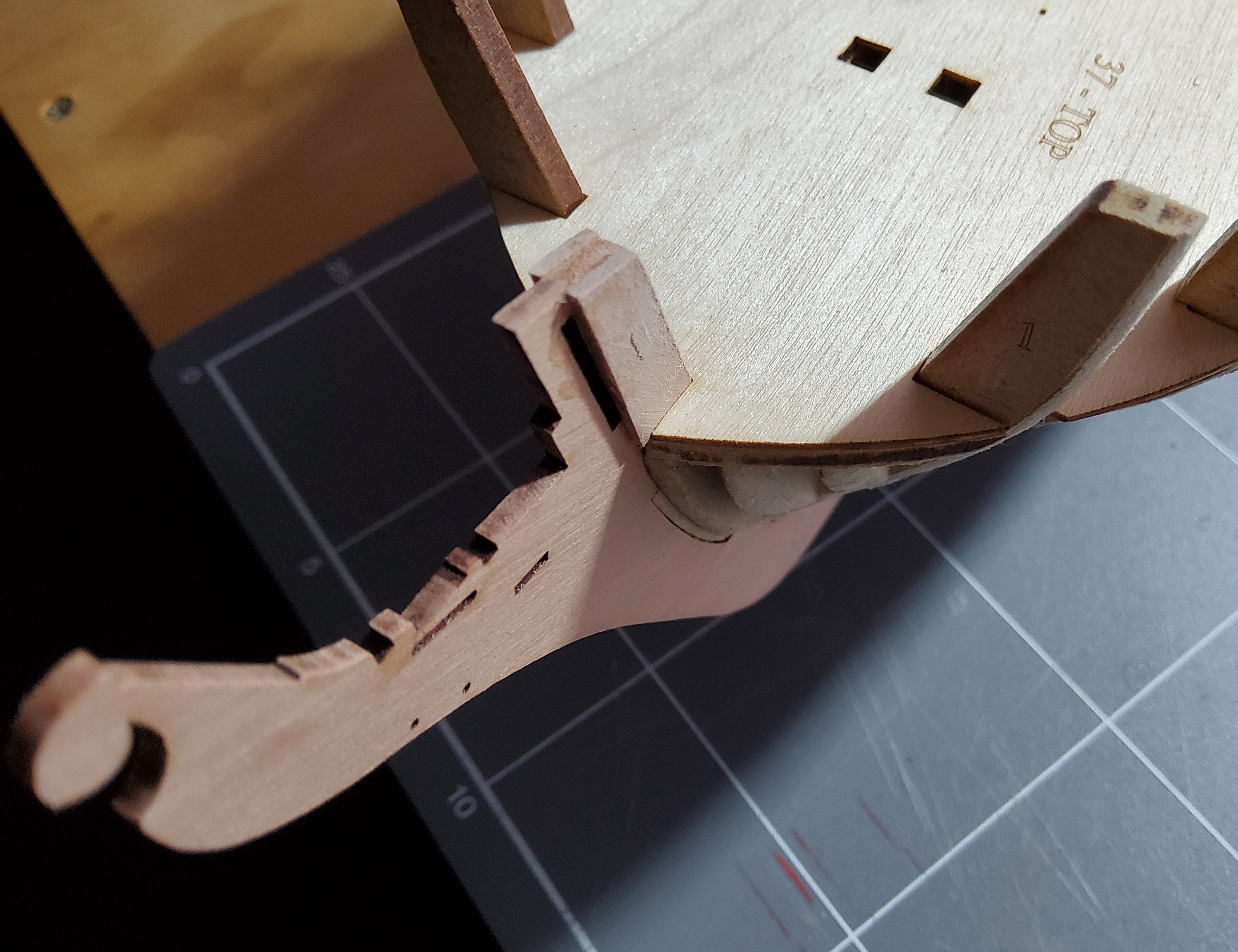
-
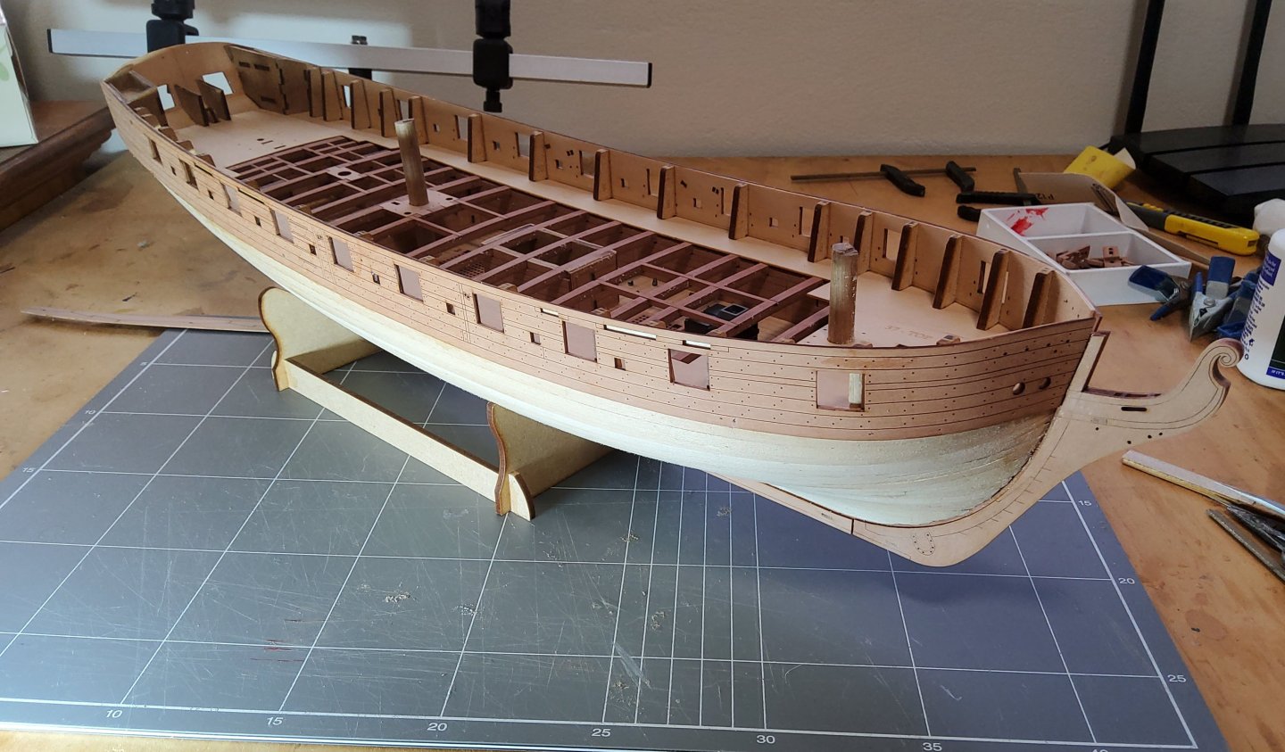
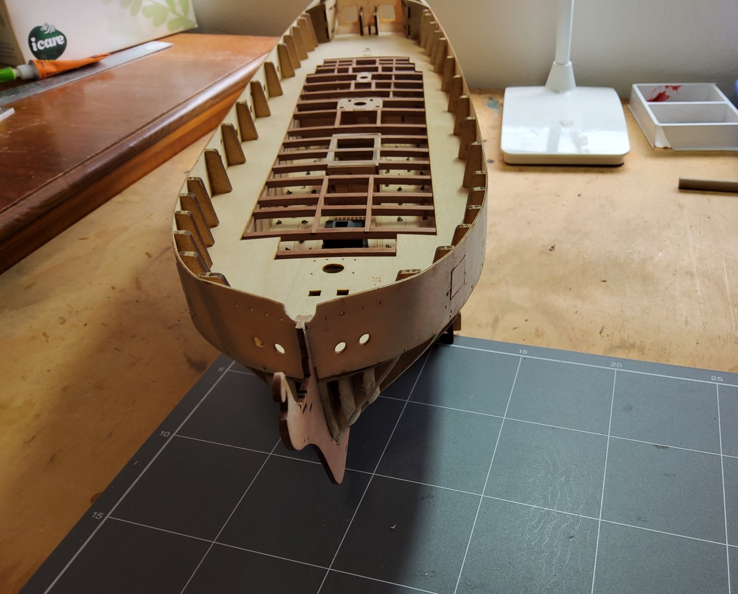
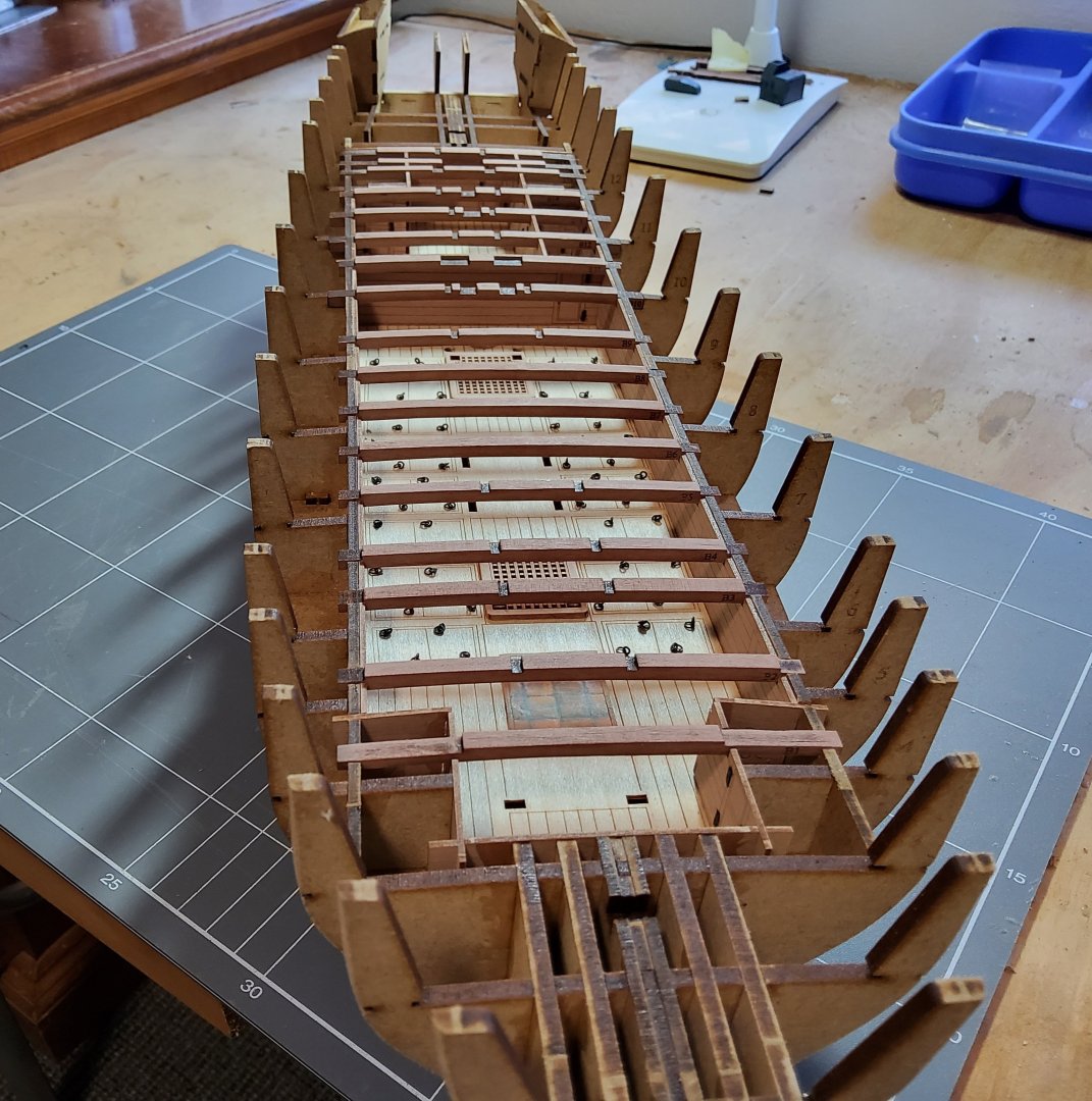
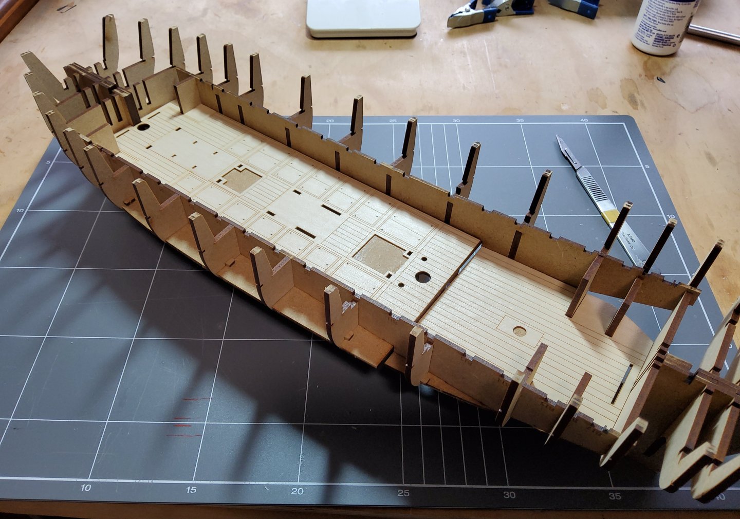
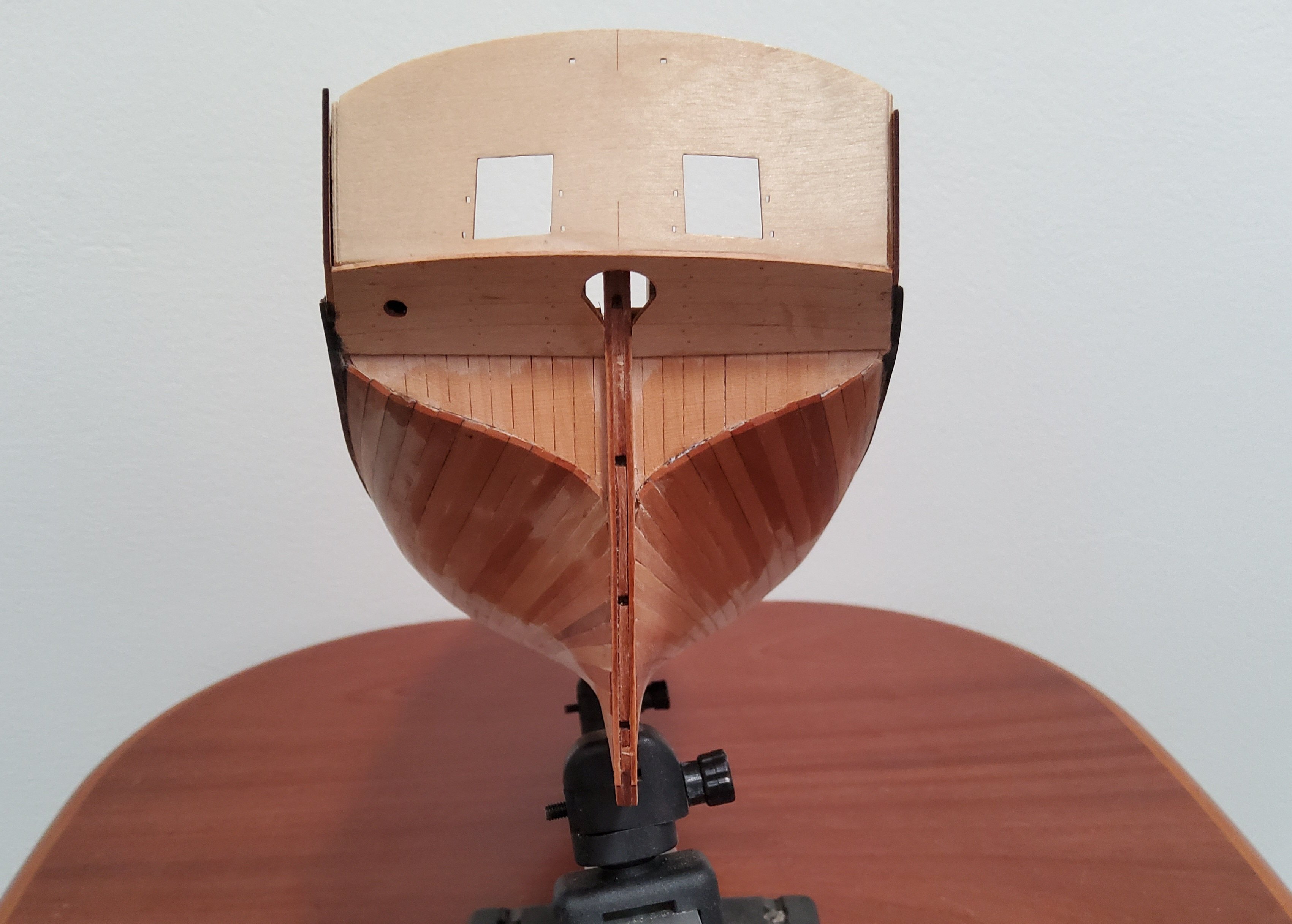
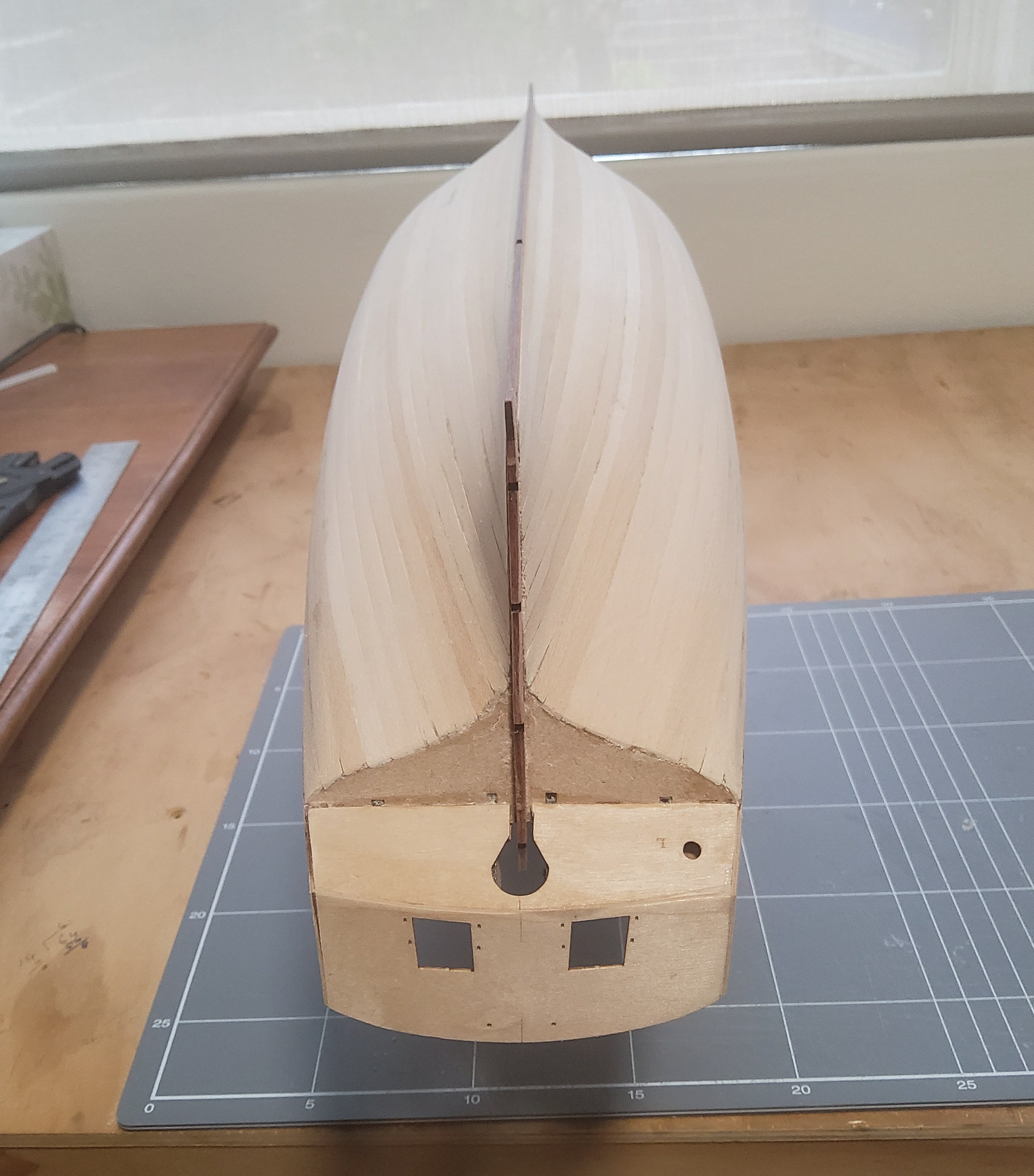
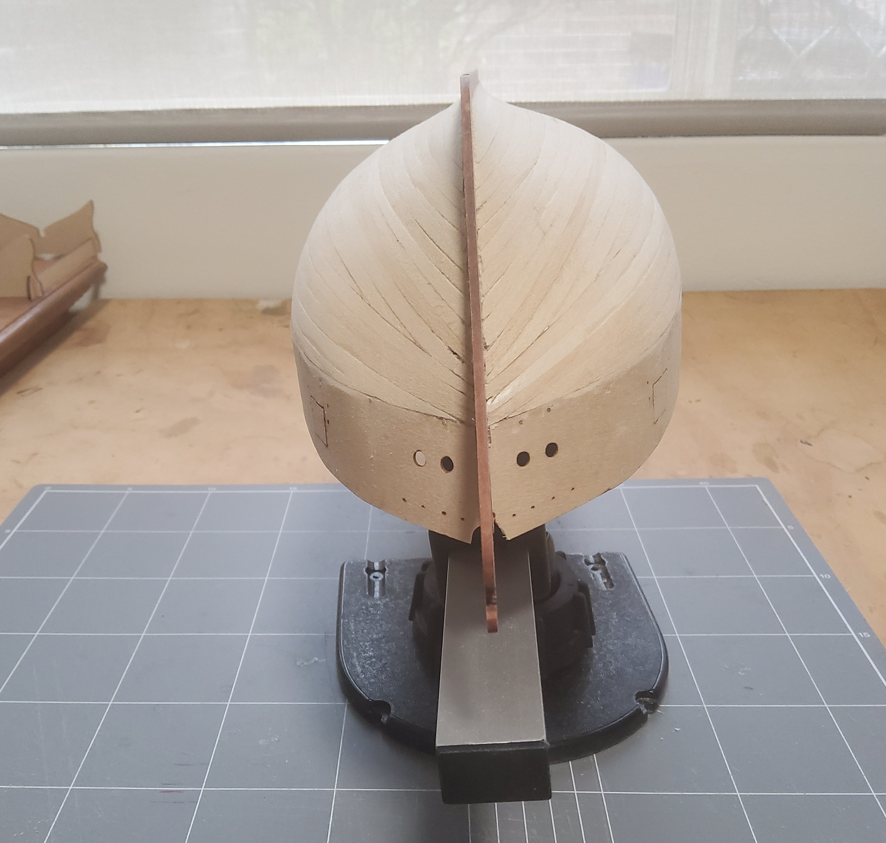
So after checking, the deck beams were all glued in place. All carlings were fitted without any problems. The ply sub-deck was then eased into place. A little tricky, but carefully did it. However the deck did not sit quite flush at the stern. You can see in this photo that the deck is bulging slightly. A close inspection showed that there was a problem around the port half of beam 16 (this is in two halves). The deck was popped off and it could be seen that the beam had been seated such that it partly blocked the slot that the deck should have clicked into. I have no idea how this could have happened as the upper surface of the beam was flush with the adjacent beams, so apparently, it was correctly seated. A misalignment somewhere. So, a little bit of surgery to clear the slot and the deck was replaced with it clicking into all the slots. The stem, keel and rudder post were all glued. These three are core pieces and will later be covered with veneer. There is a slight gap between the stem and the keel, but this will be covered by veneer, so nothing needs to be done about it. As B.E. found out, the rudder post needed some trimming to fit over bulkhead 17. Two supports for the prow were glued and pinned. The instructions for this step in the manual are out of sequence (too early) and it could not be done until the stem etc had been fitted. The two ply stern counters were added to the hull, the lower first. The upper needed some trimming to match the curve of the lower where the two met. Cheers


-
Interesting method of doing the wales/planking B.E. I'll have to have a serious think about it when I get to that stage in my build. Thanks.
- 332 replies
-
- 3
-
-
- Harpy
- Vanguard Models
- (and 1 more)
-
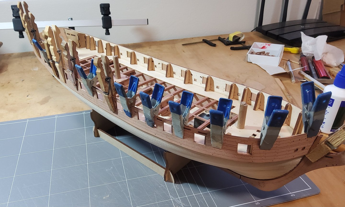
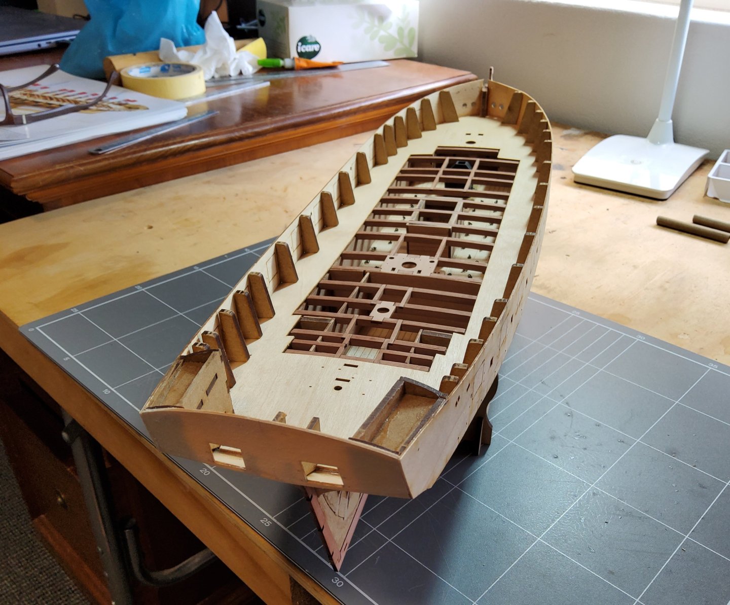
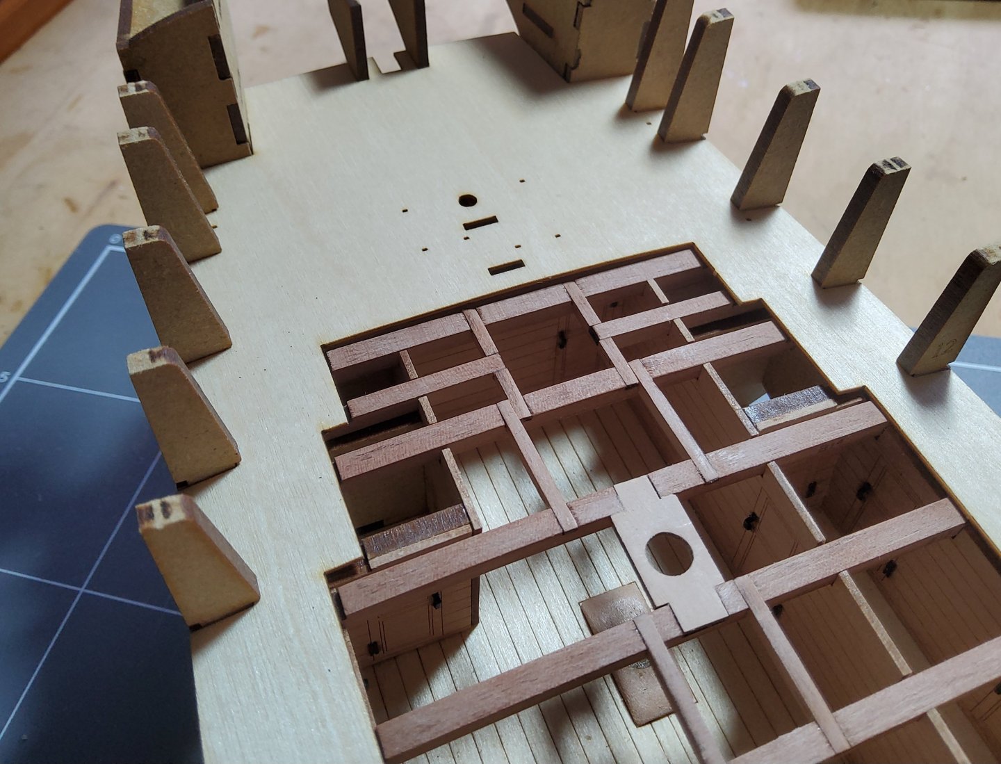
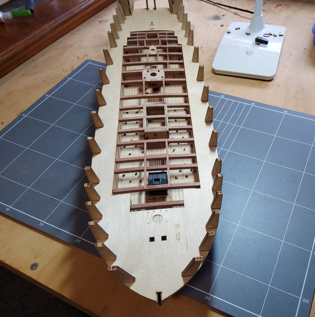
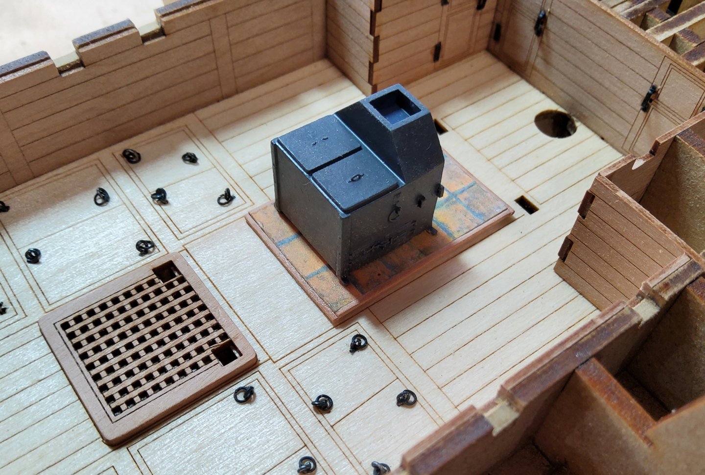
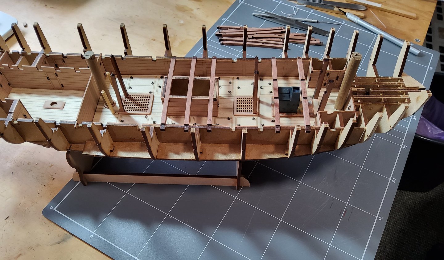
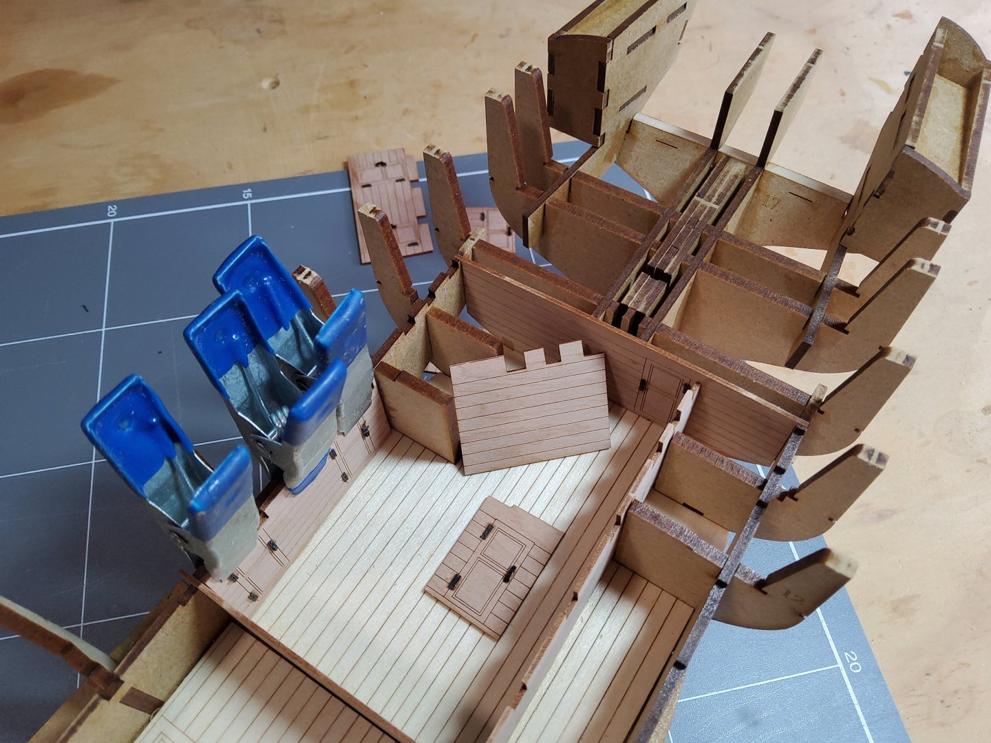
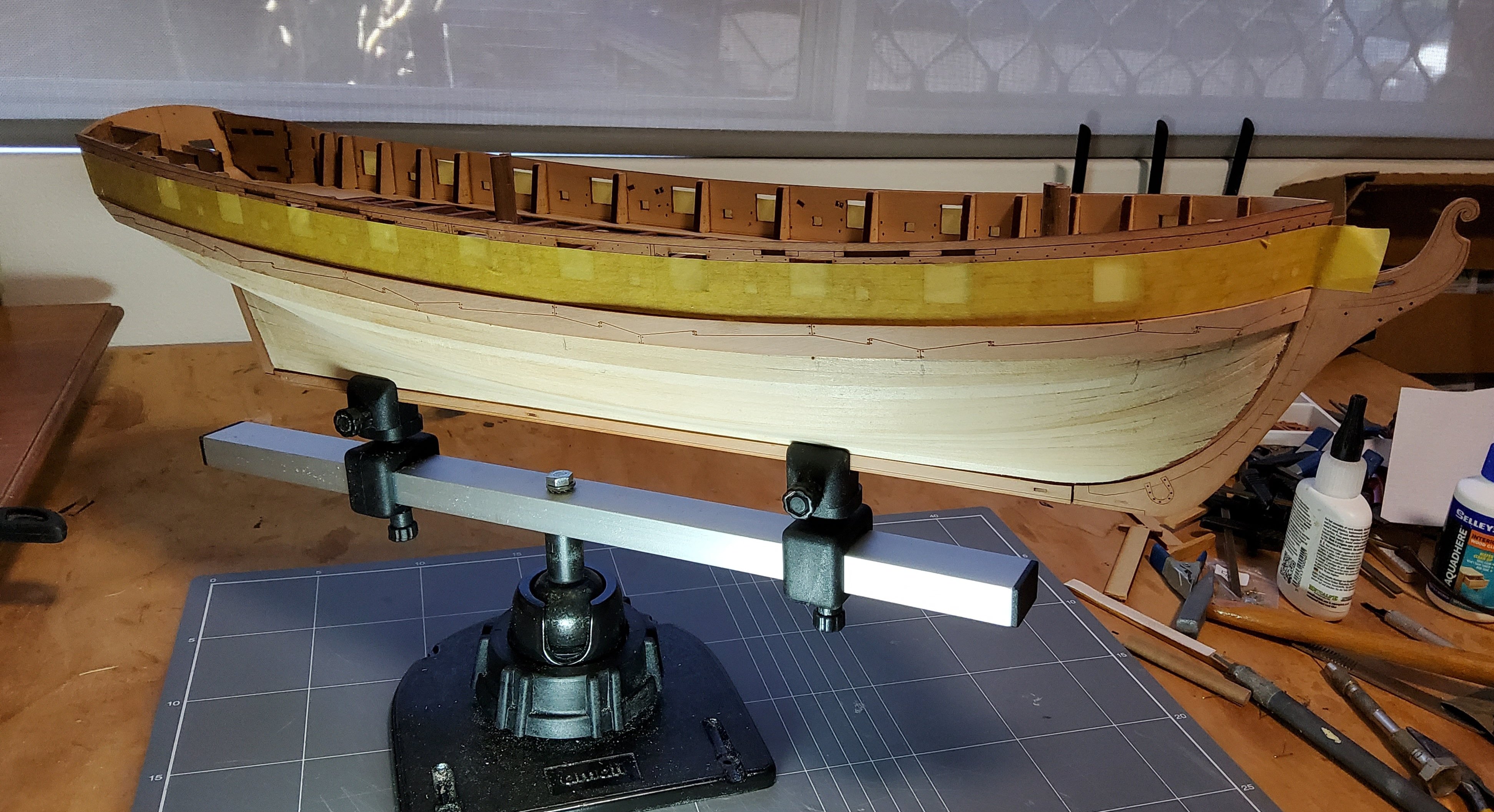
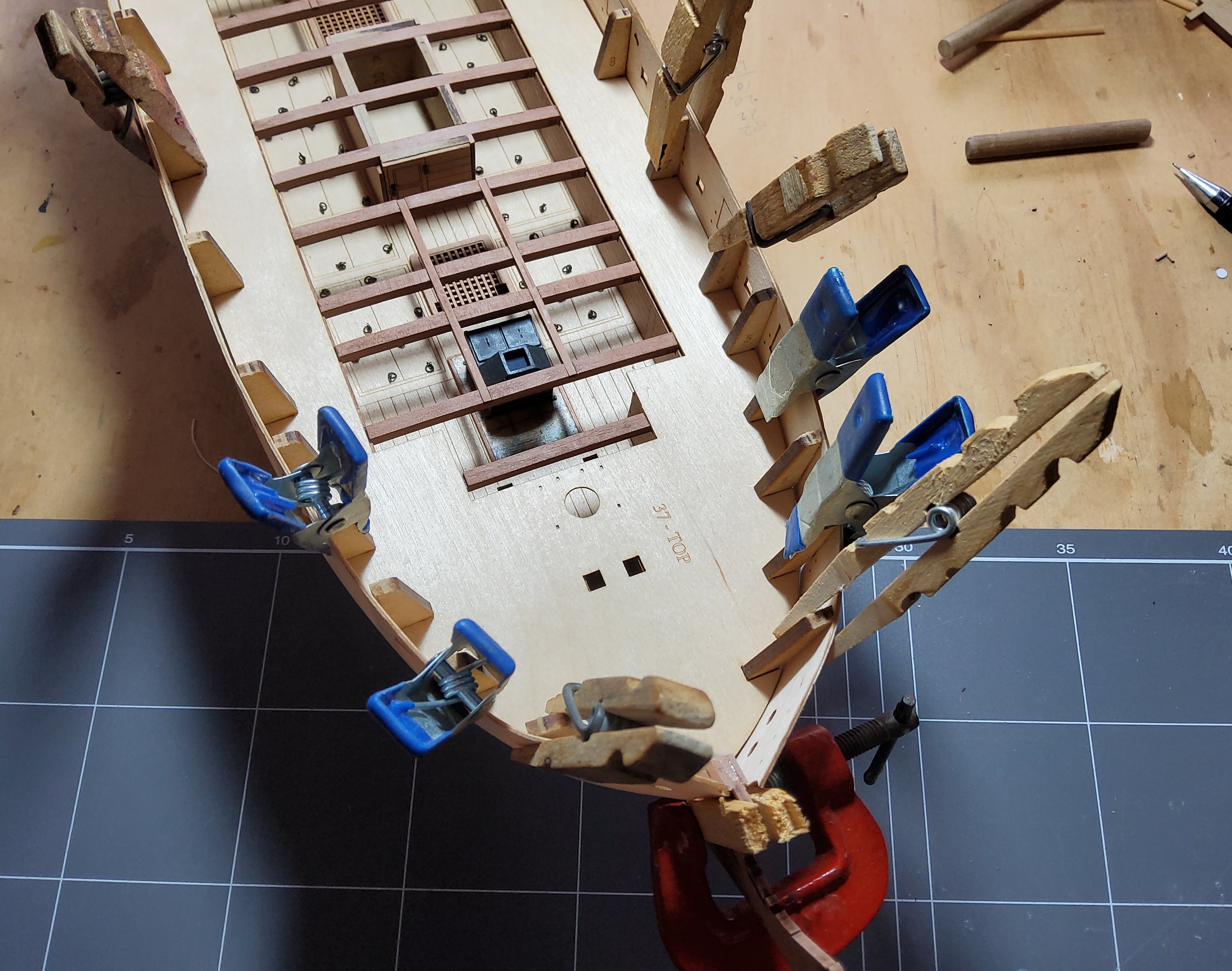
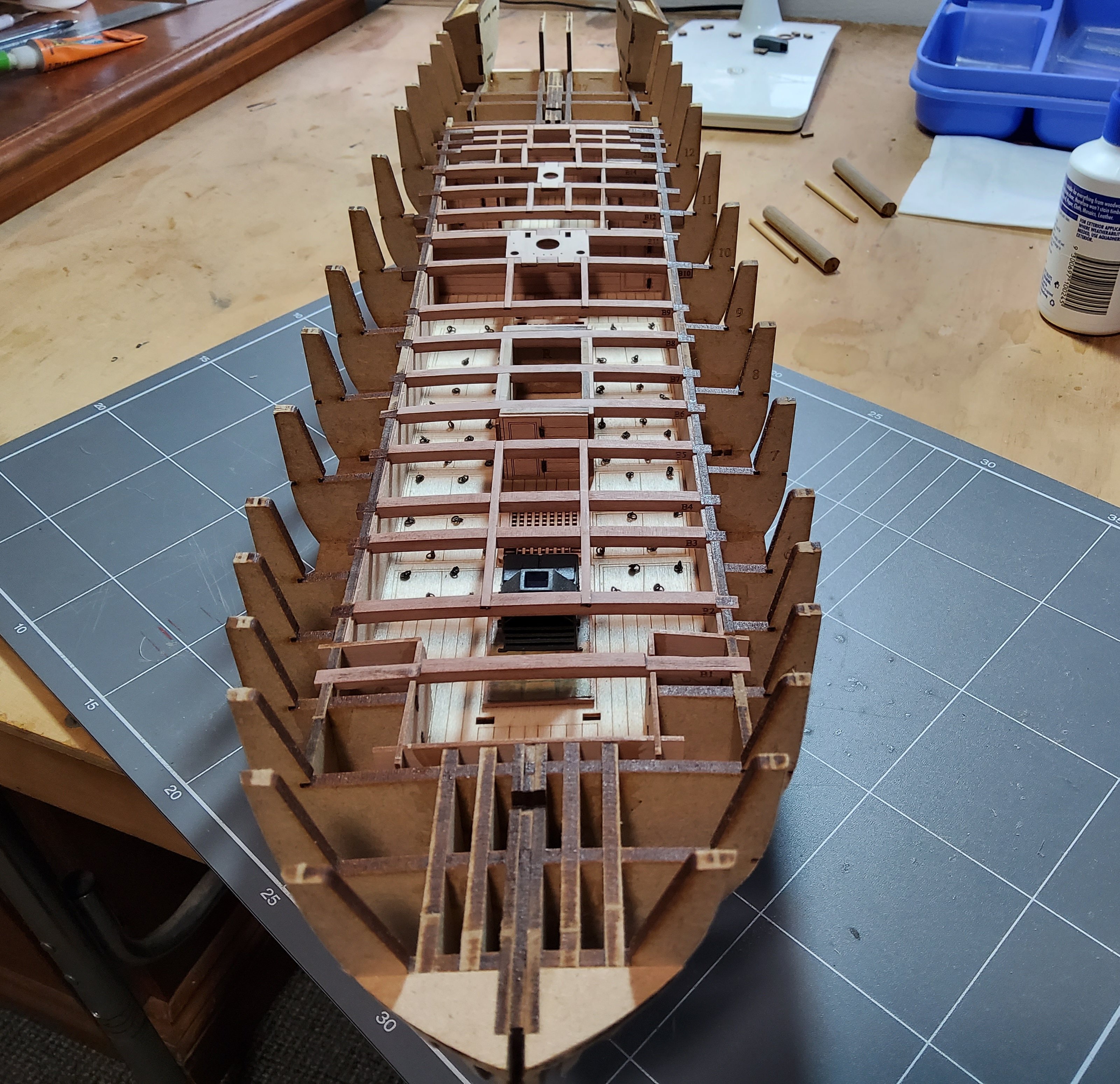
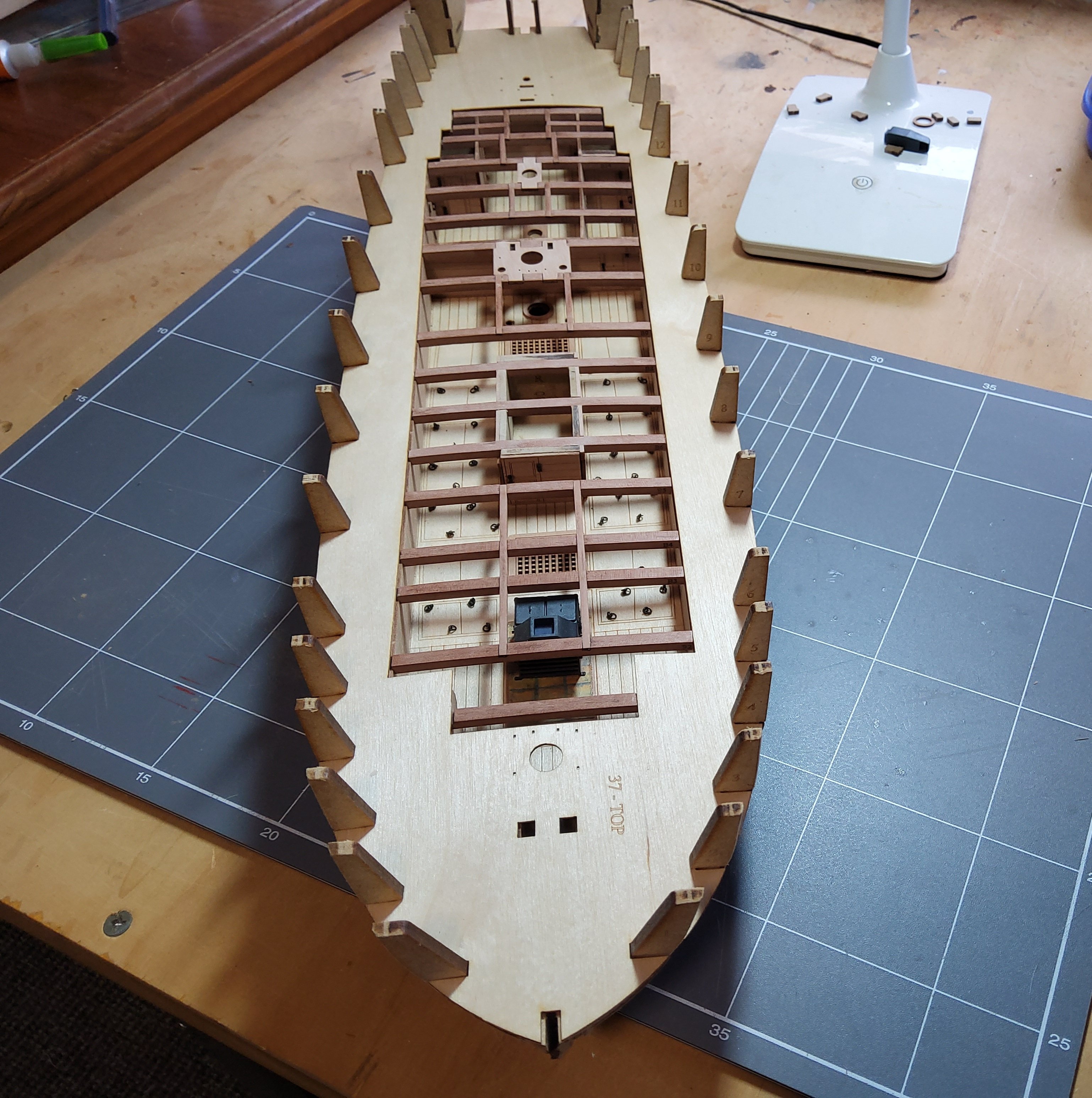
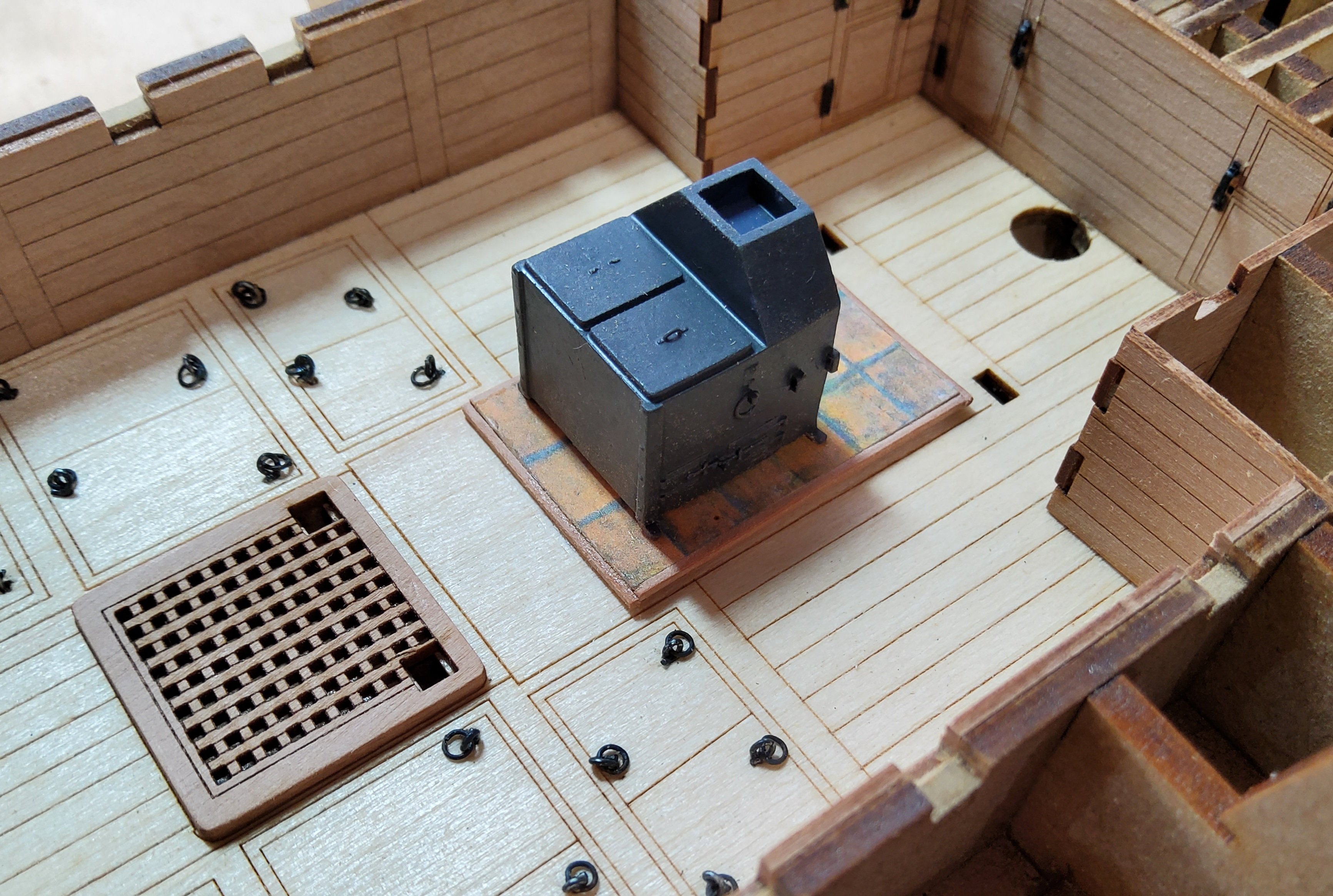
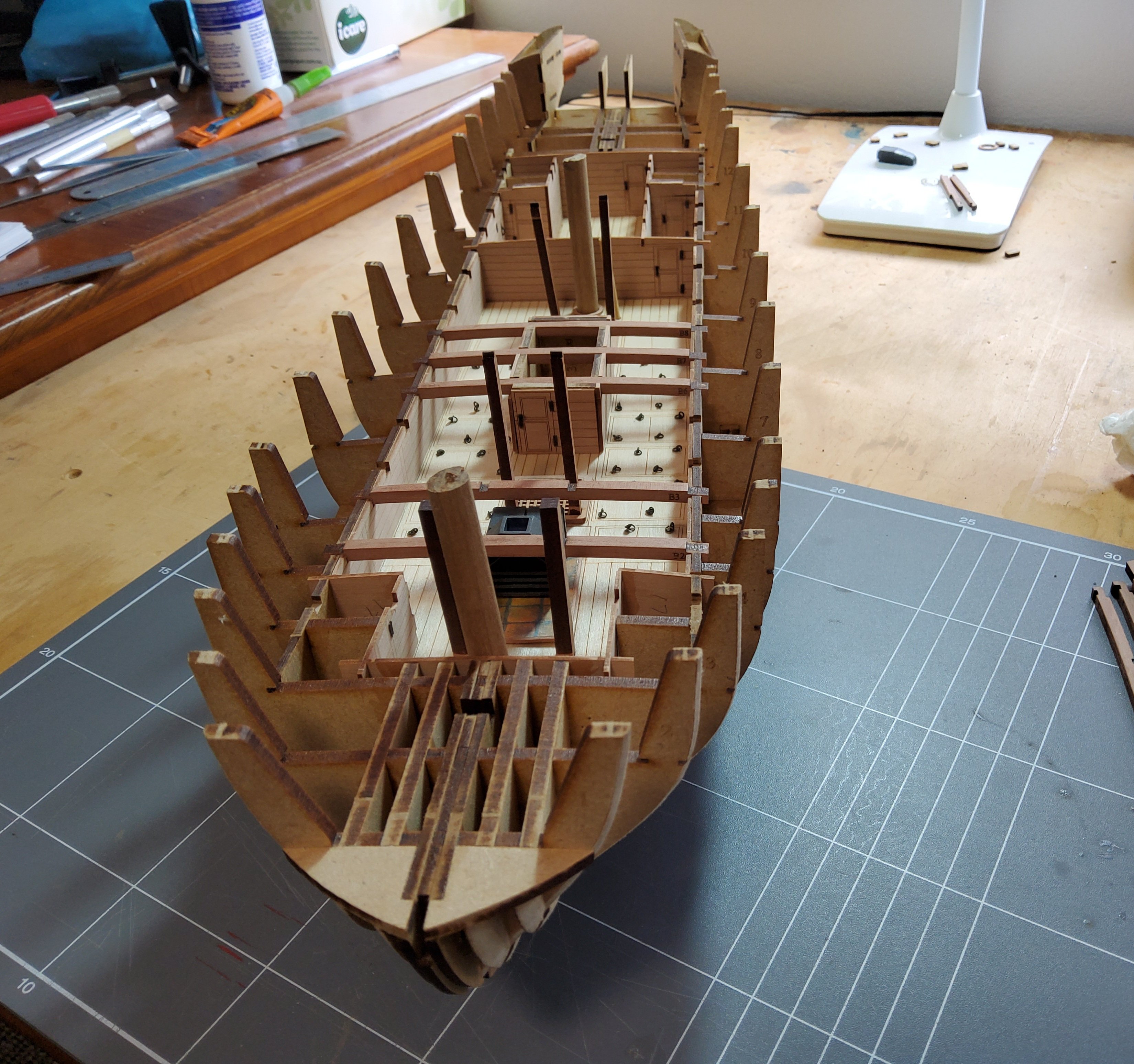
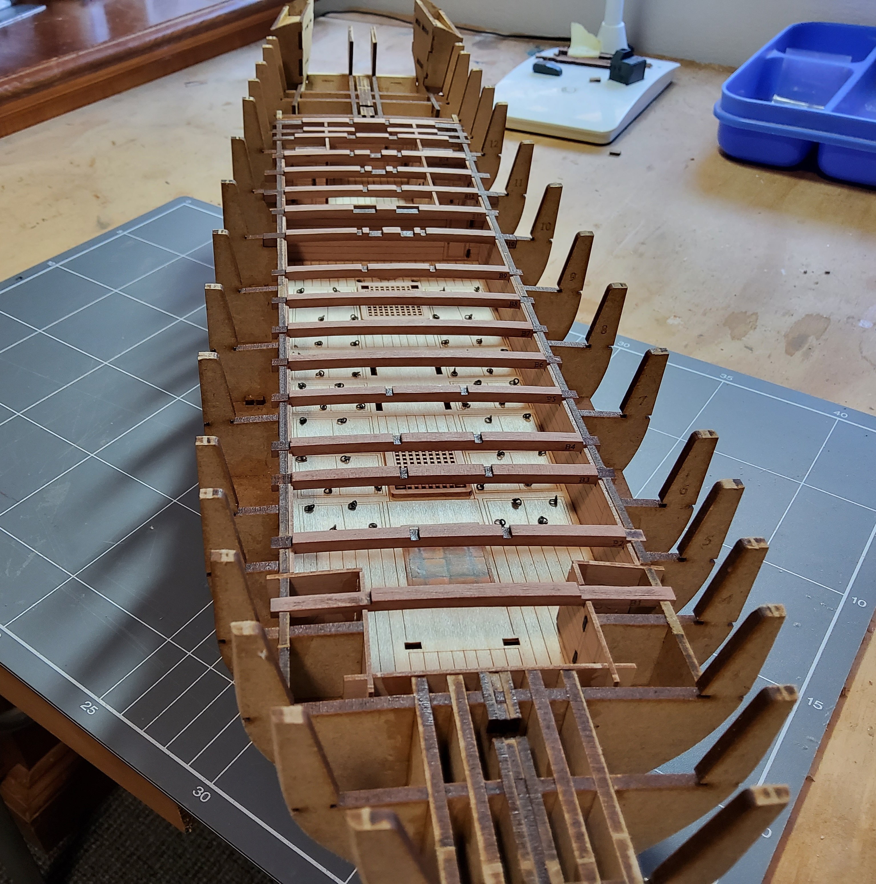
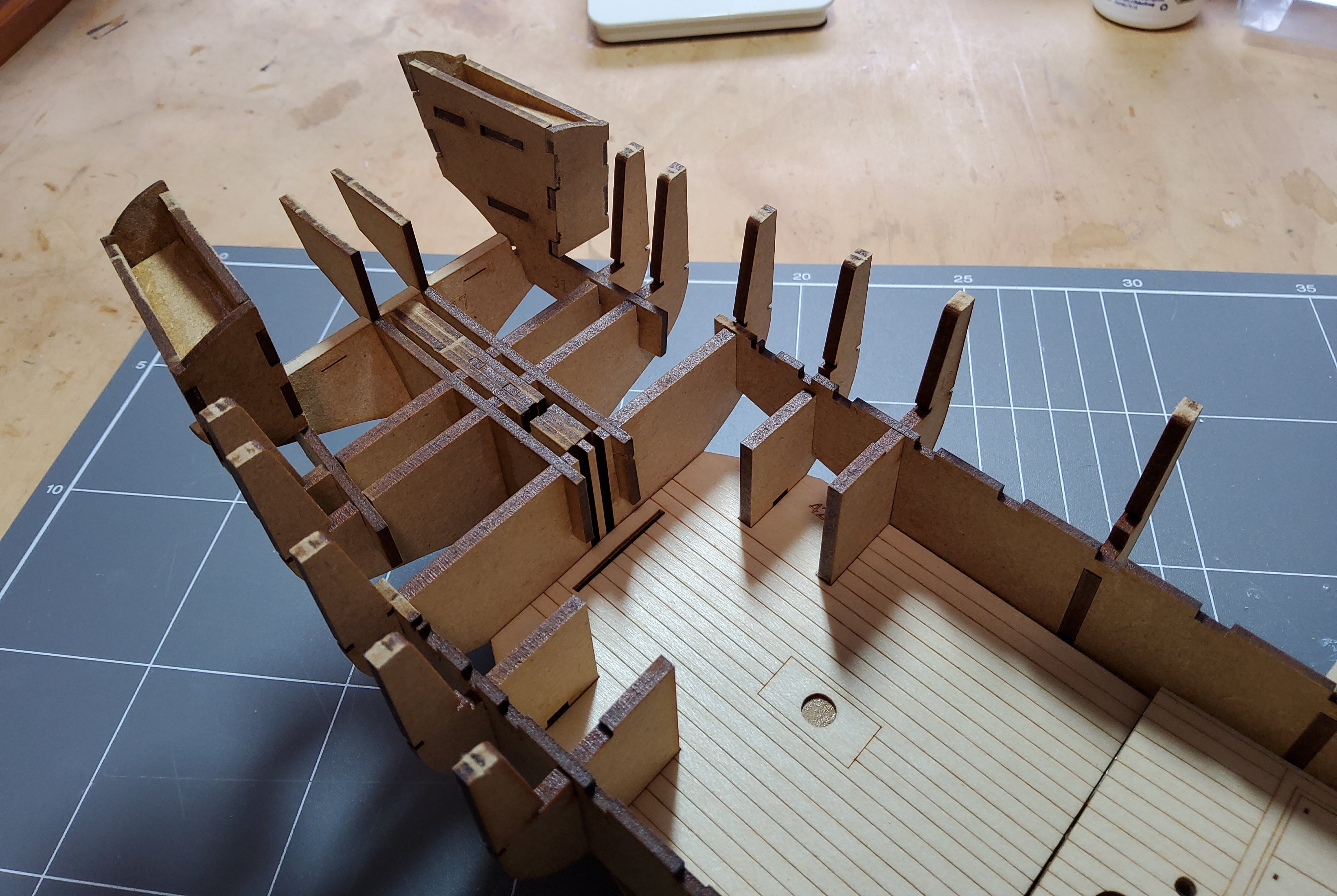
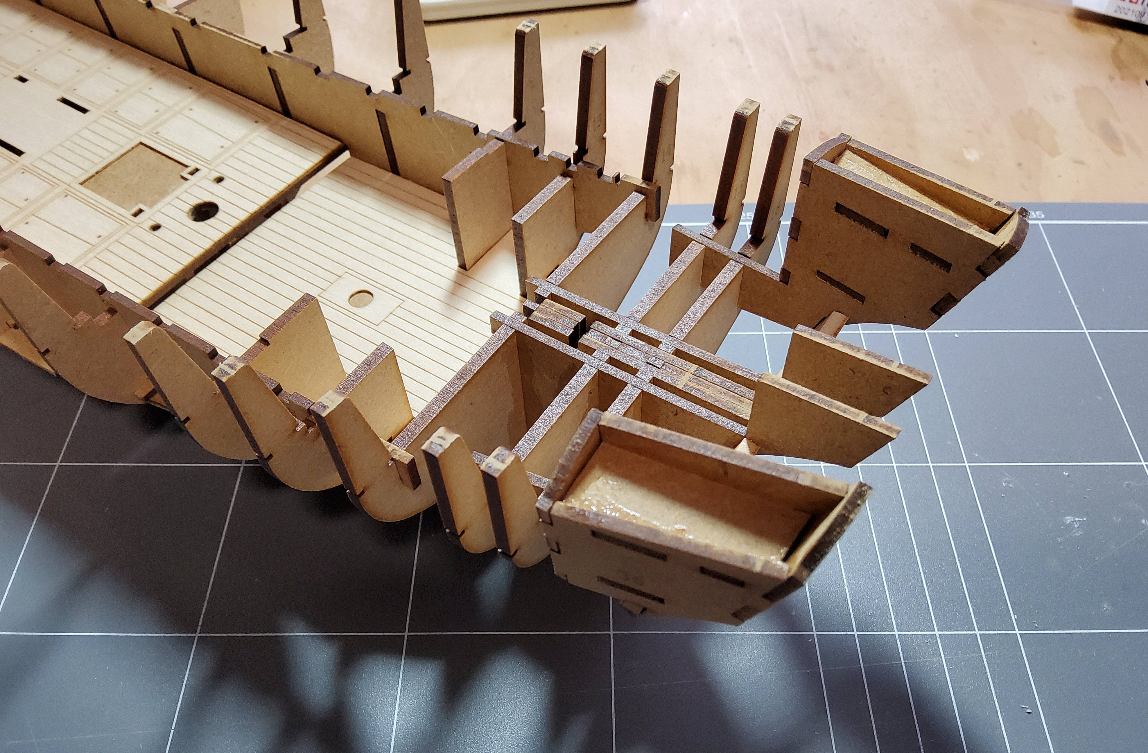
Once all the partitions were in place, I dryfitted all the deck beams after sanding the char off the tops. A few needed a touch with a sanding stick to properly seat, but otherwise all was good. There are three beams that cross the sail room. The latter was put in place, not glued, and the fit of the beams checked. The location of the stove relative to the beams fore and aft was also checked. Finally, as this is the last time before the deck is closed off, dowels were used to represent the masts and pump outlets and inserted to make sure their respective mounting holes were clear. The three bitts were similarly checked. The sail room and stove were then glued in place. I too have copied B.E. and put a base under the stove. After finding a downloadable tile pattern that I liked (not as easy as you might think), I fiddled around on the computer to get a 6x3 print that seemed to be of an appropriate size. It was edged with 1x1mm pear. The stove is not glued in place in this photo. Cheers

-
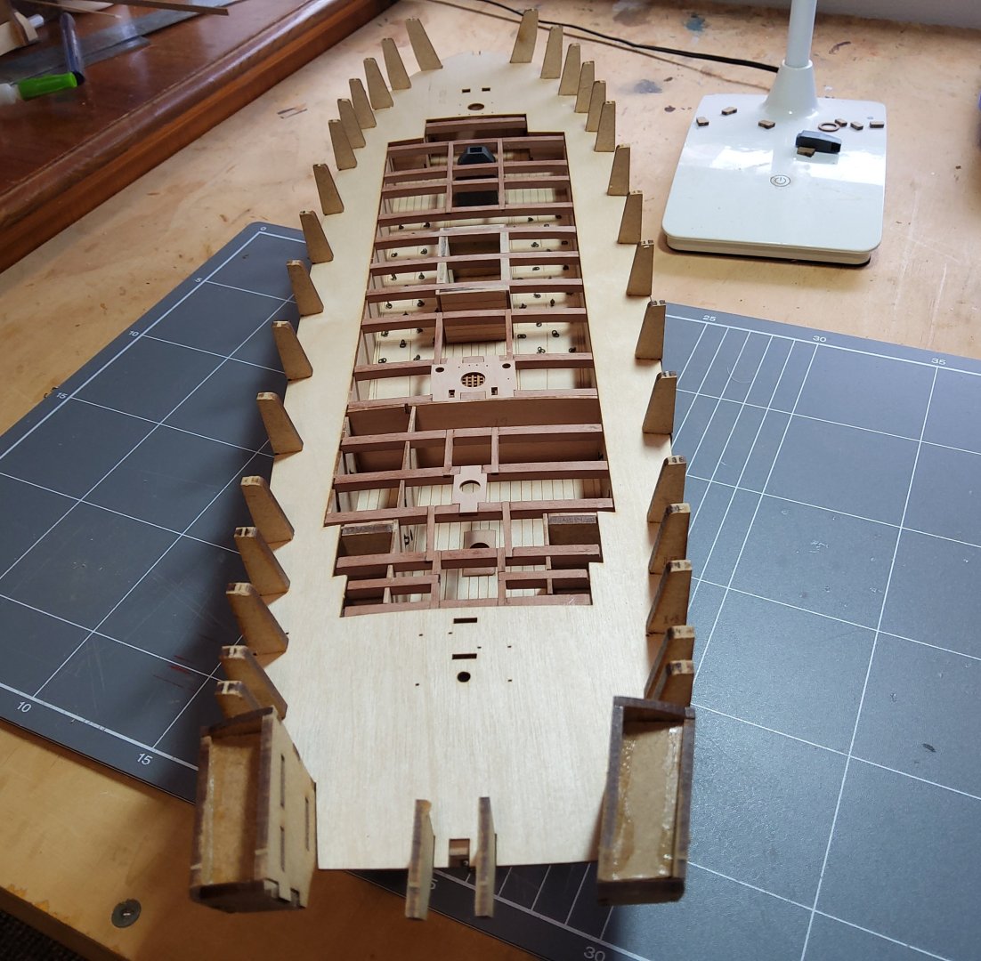
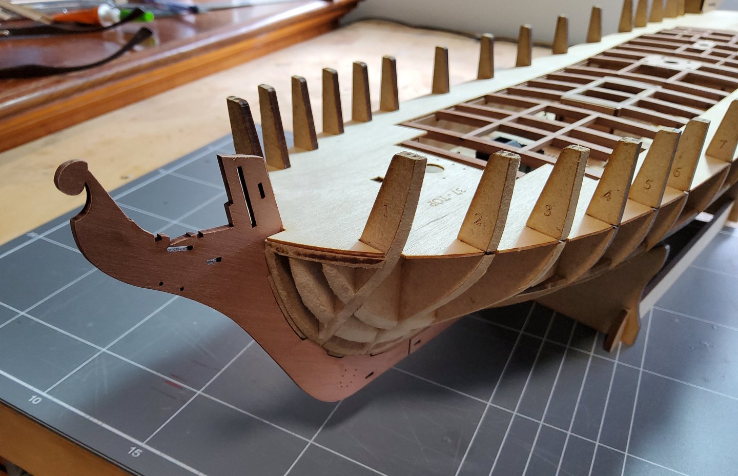
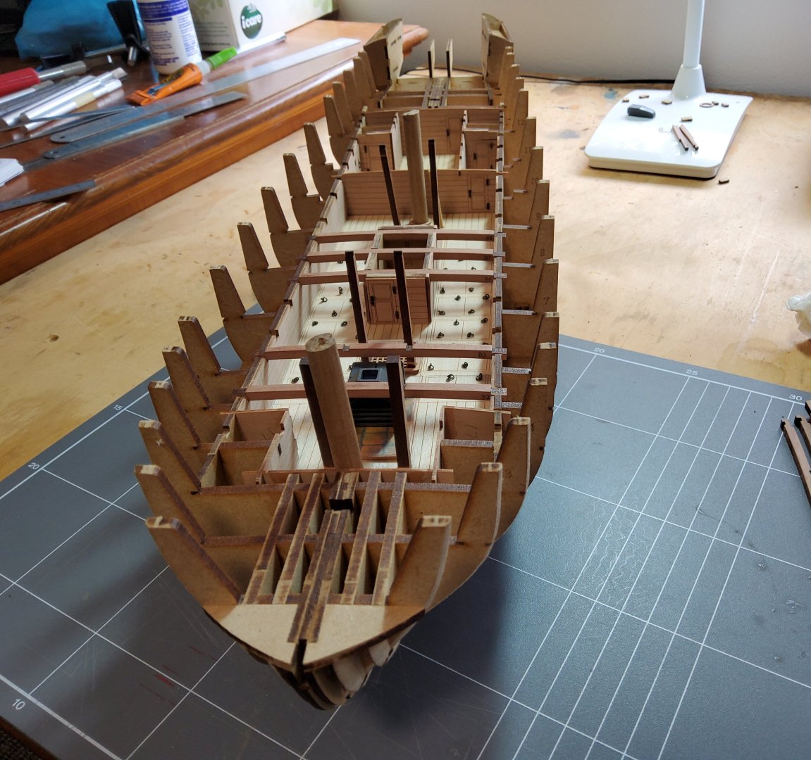
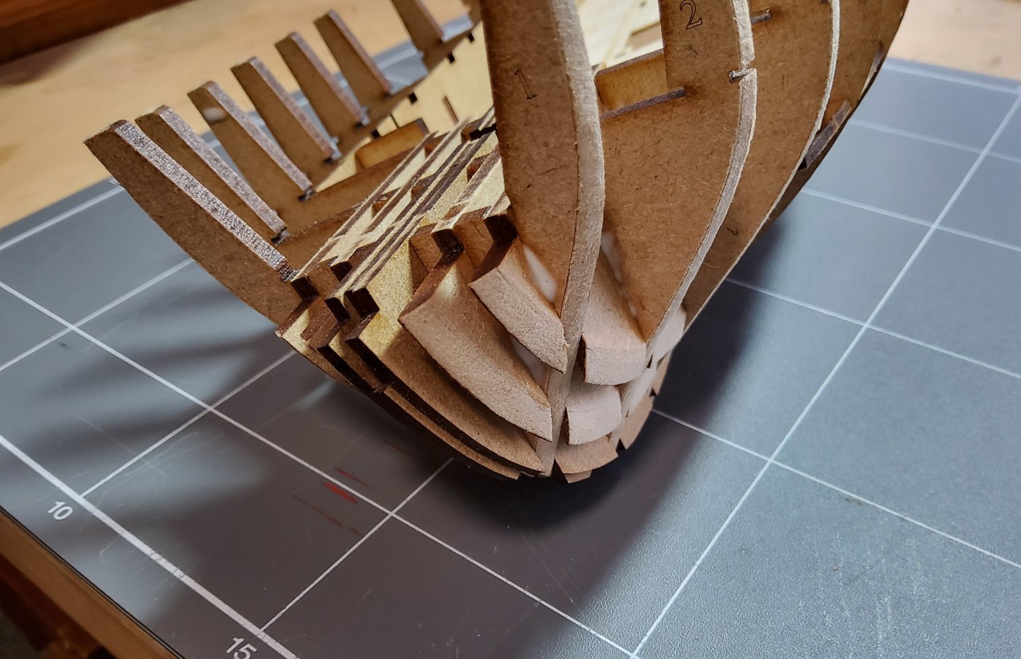
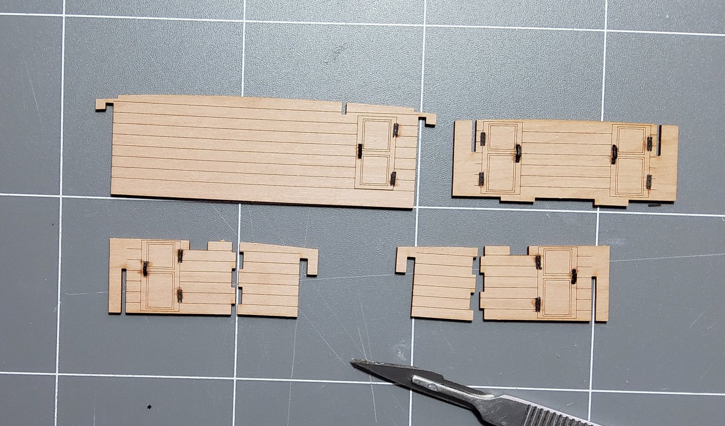
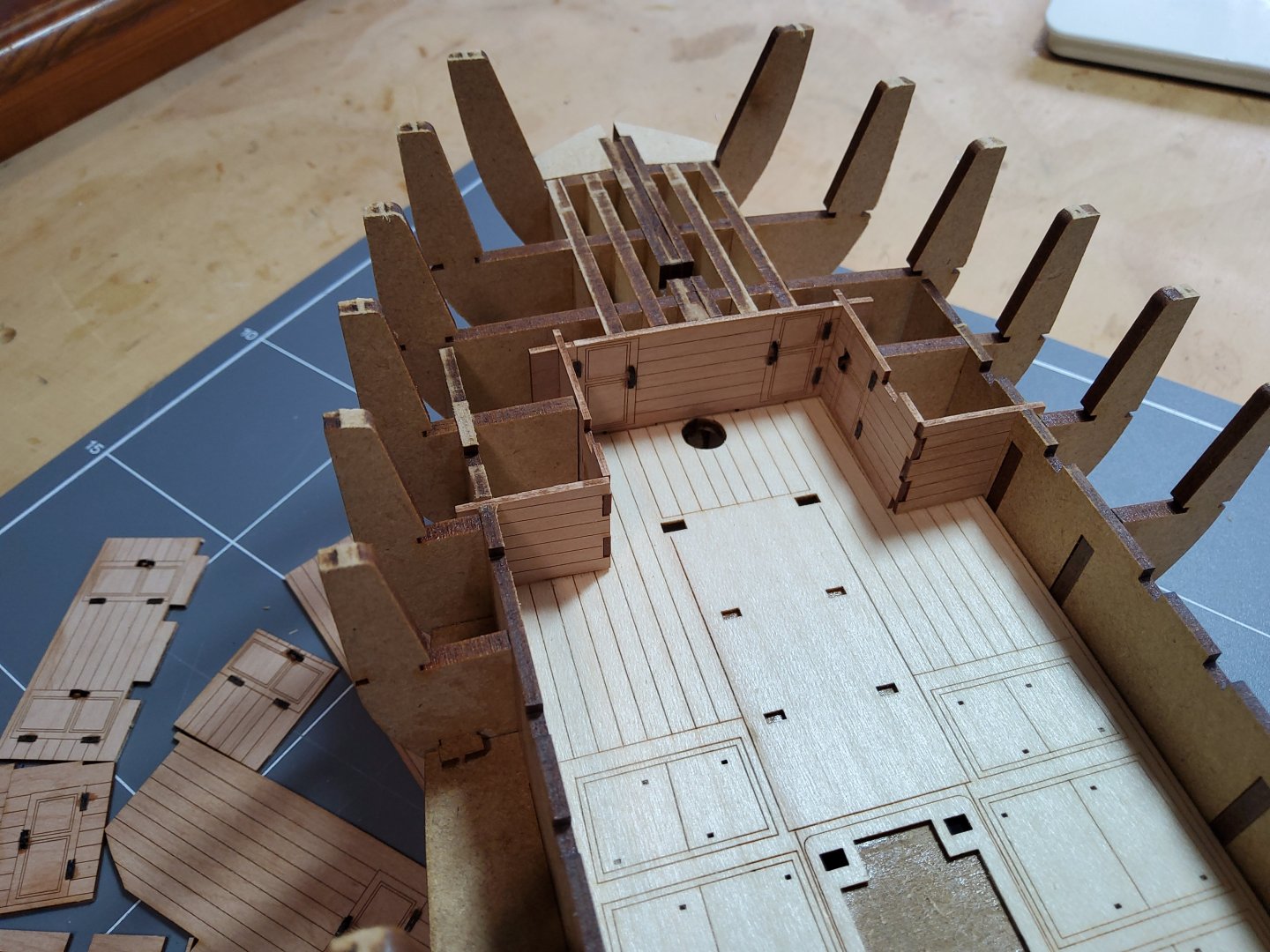
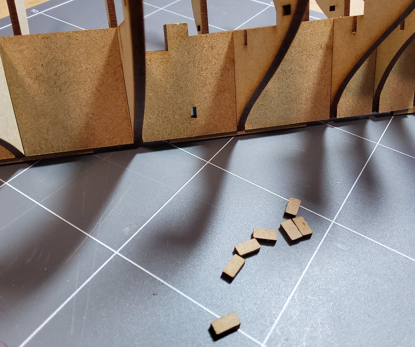
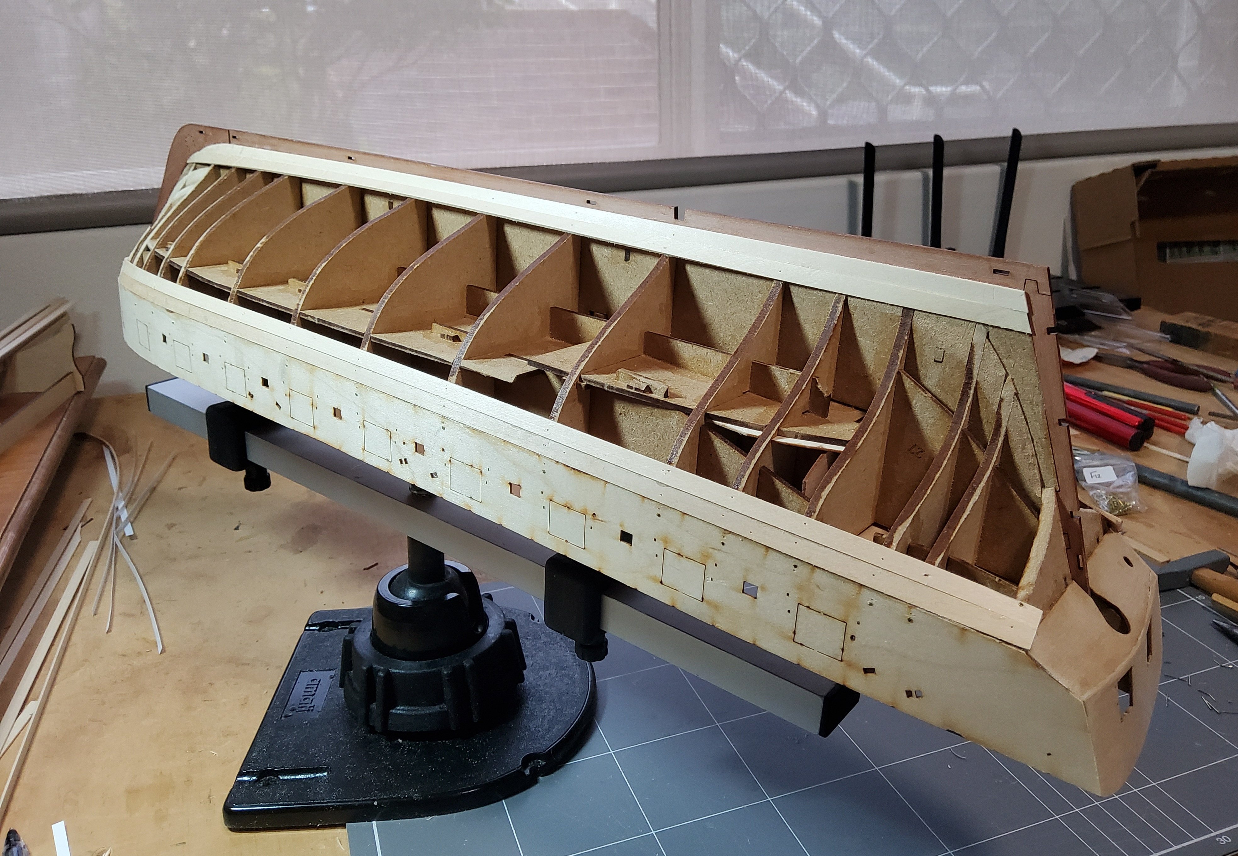
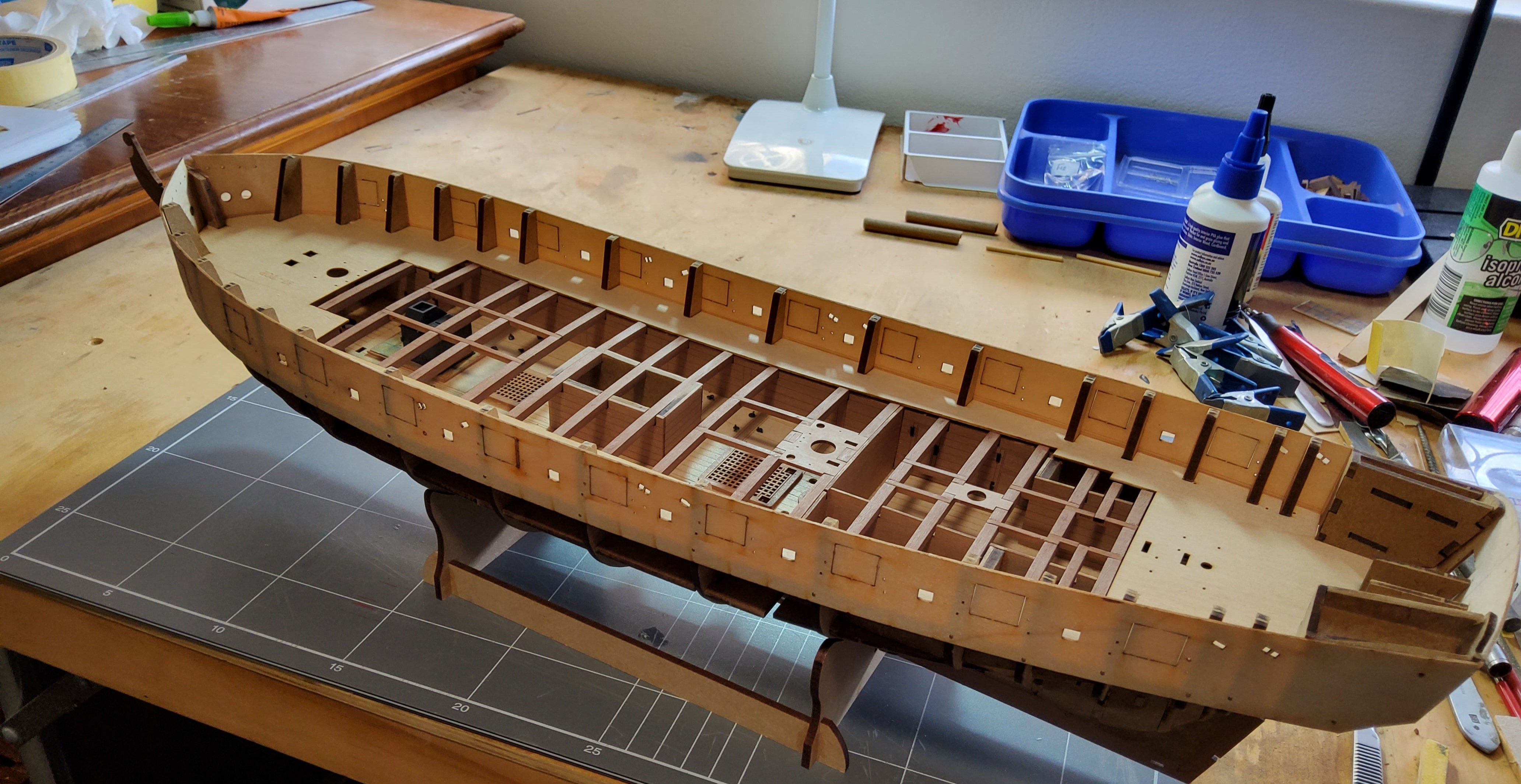
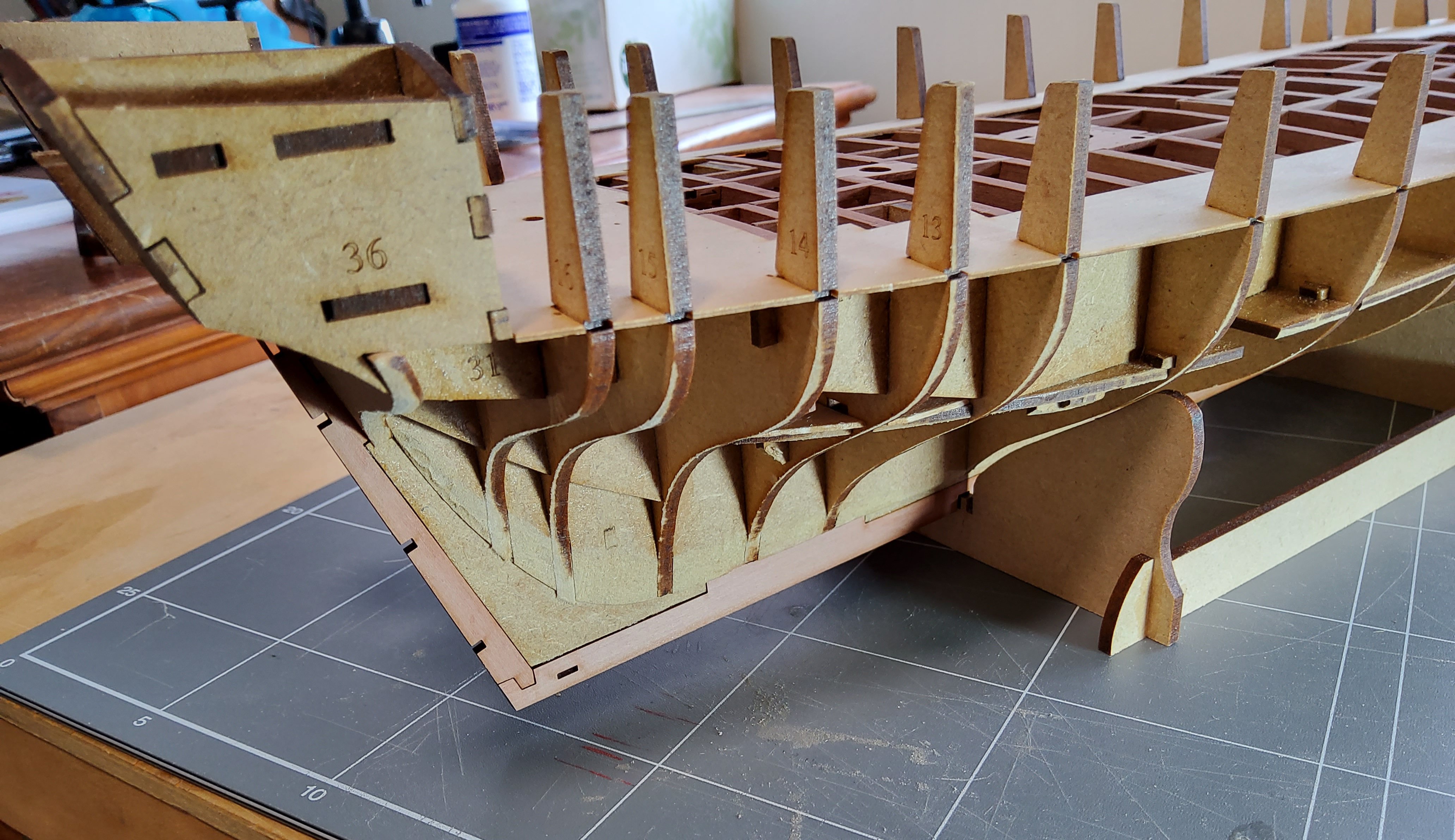
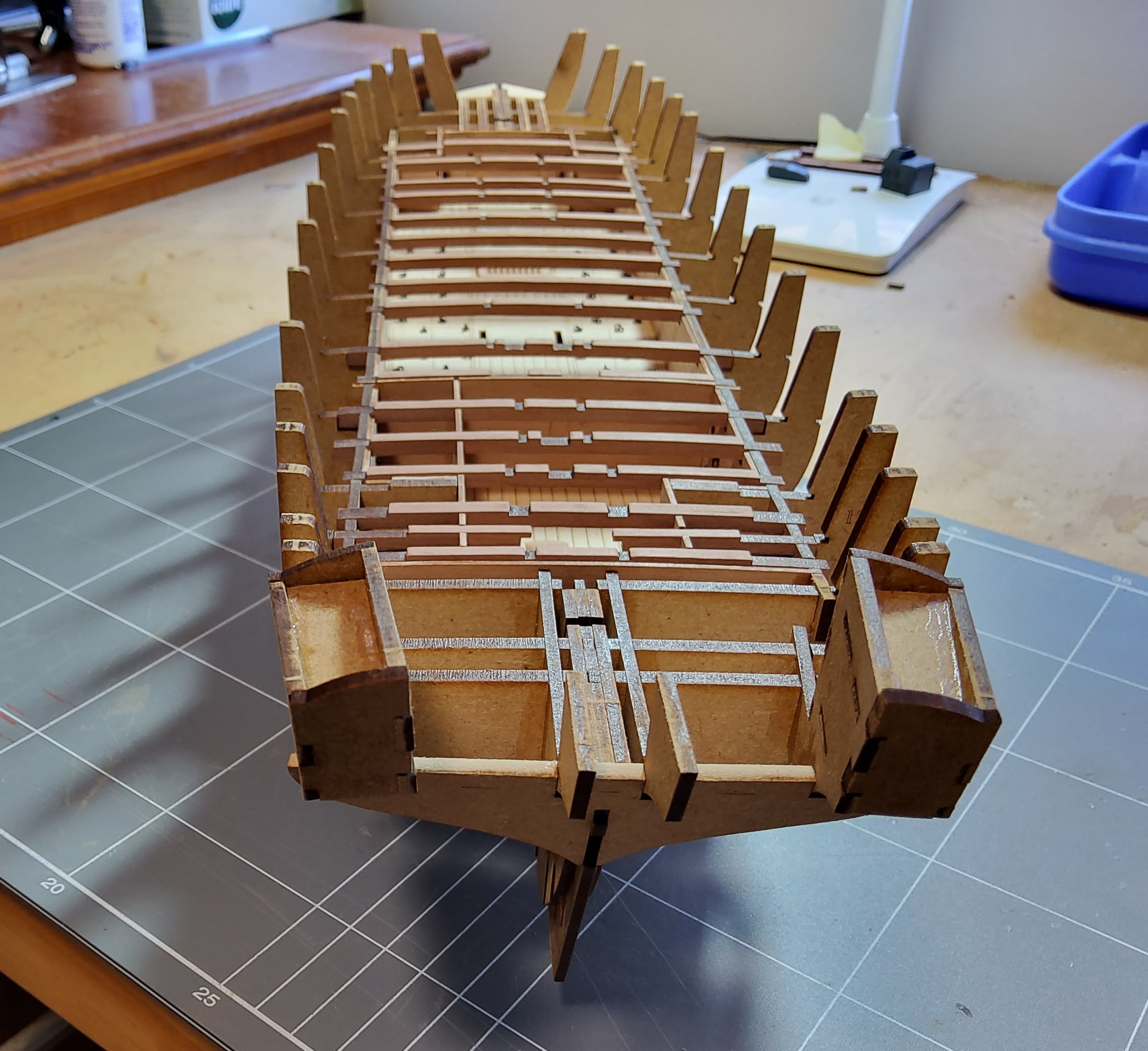
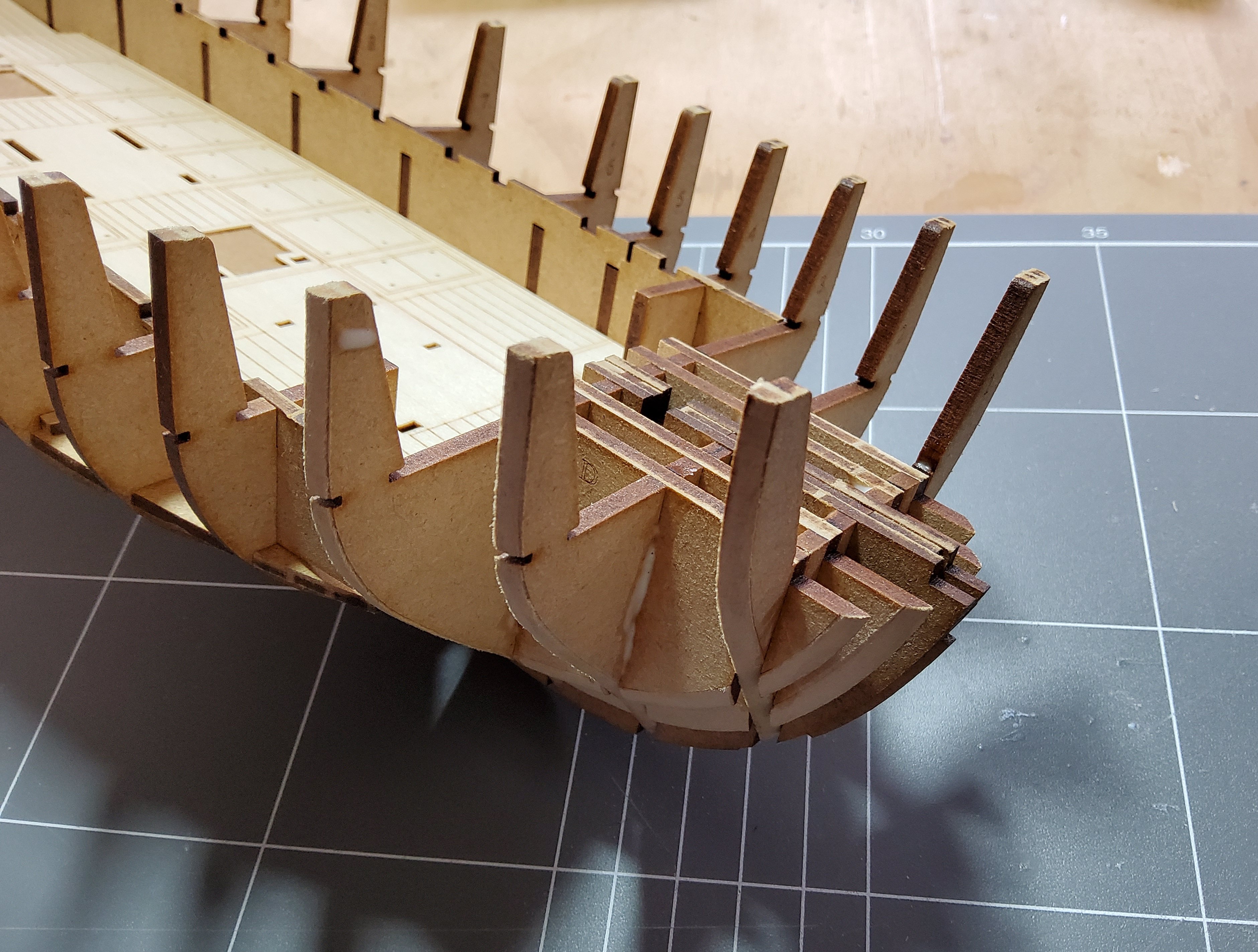
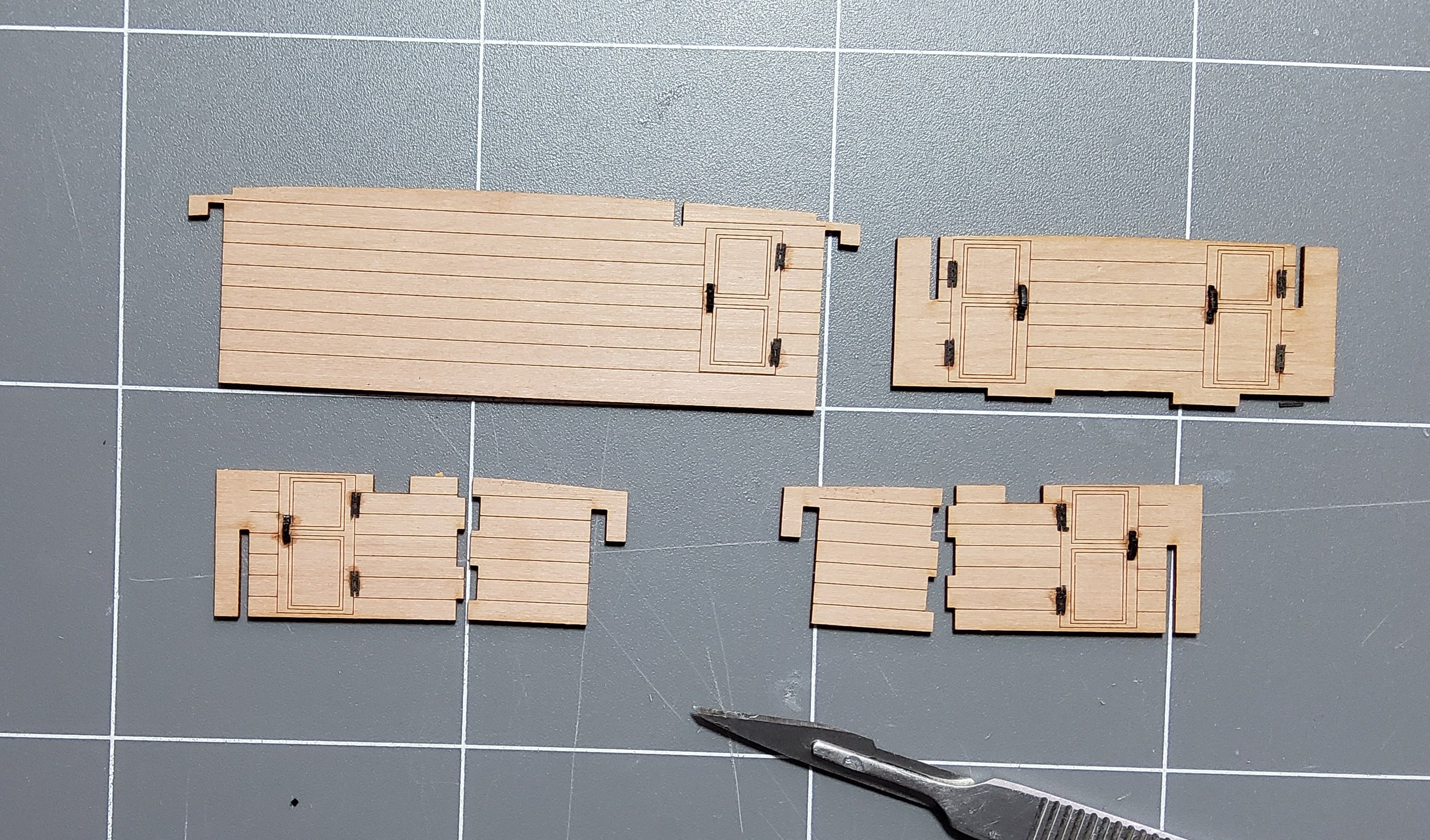
Next, four formers, two per side, were fitted to the bow, slotting easily over the bulkheads. Again chamfering was done first. Finally a small platform was glued on top to complete the bow structure. Even though chamfering has been done, it is apparent that quite a bit of fairing will have to be done before planking takes place. There are two cabins, one each side, at the stern and these are assembled from mdf. The completed framework for the cabins. The one on the left is obviously not quite right, but that part had not yet been glued, so no problem to correct it. The cabins are slotted into the rear bulkheads, including No17, which is now glued in place. Various pieces which will go to form the walls of the small cabins on the lower deck. There are two parts, 180 and 186, which are not mentioned in the manual. An examination of the plan, Sheet 6, showed where they would go, but they are out of sight and unnecessary for the build so can be left off. However, there is some mismatch between the labelling of the parts on the laser-cut sheet and the plan. Parts 186 and 187 have become interchanged and the plan shows two parts 180. Not a real problem as the various parts only go together one way and the photos in the manual are clear. The kit comes with eyebolts that are supposed to represent door handles. I followed B.E.’s advice though, and bought laser-cut handles and hinges from Syren. Tricky little things to glue. Assembly under way at the bow and the stern. Cheers


.thumb.jpg.e4614f438ece5c98c4fe4ce52c55d341.jpg)
-
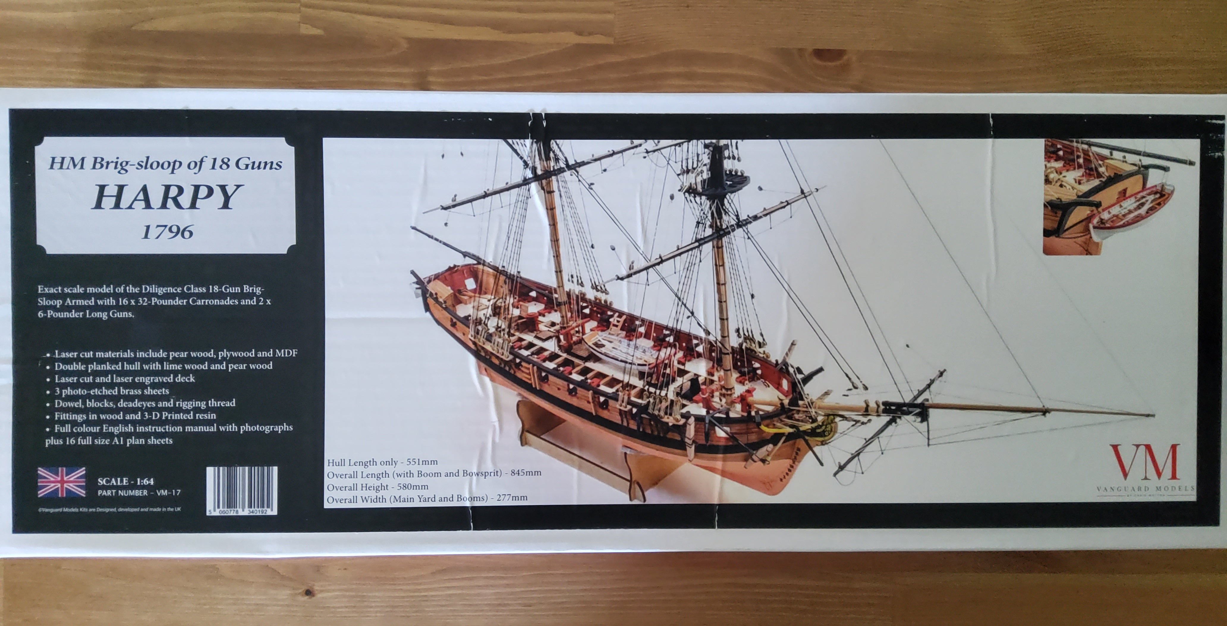
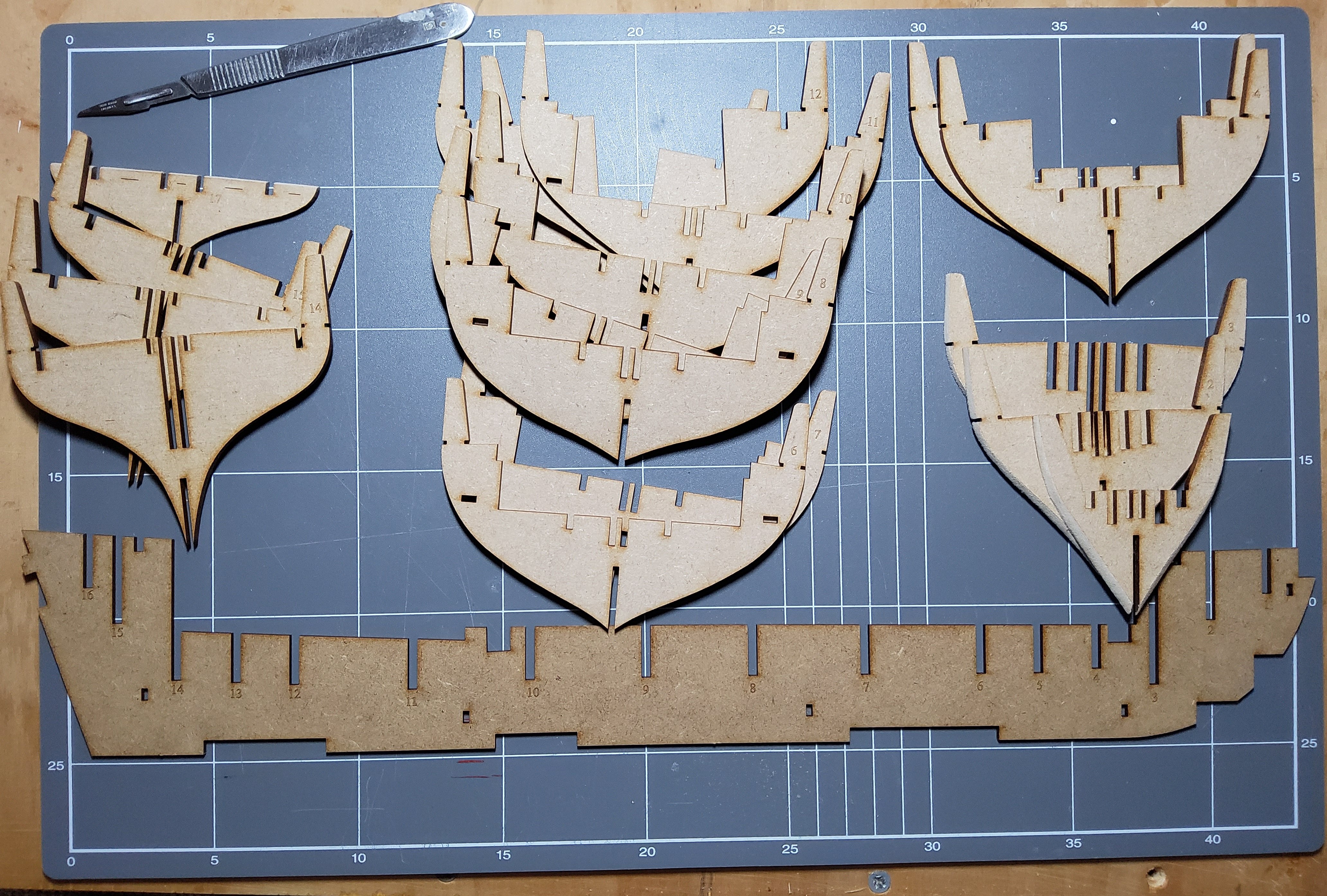
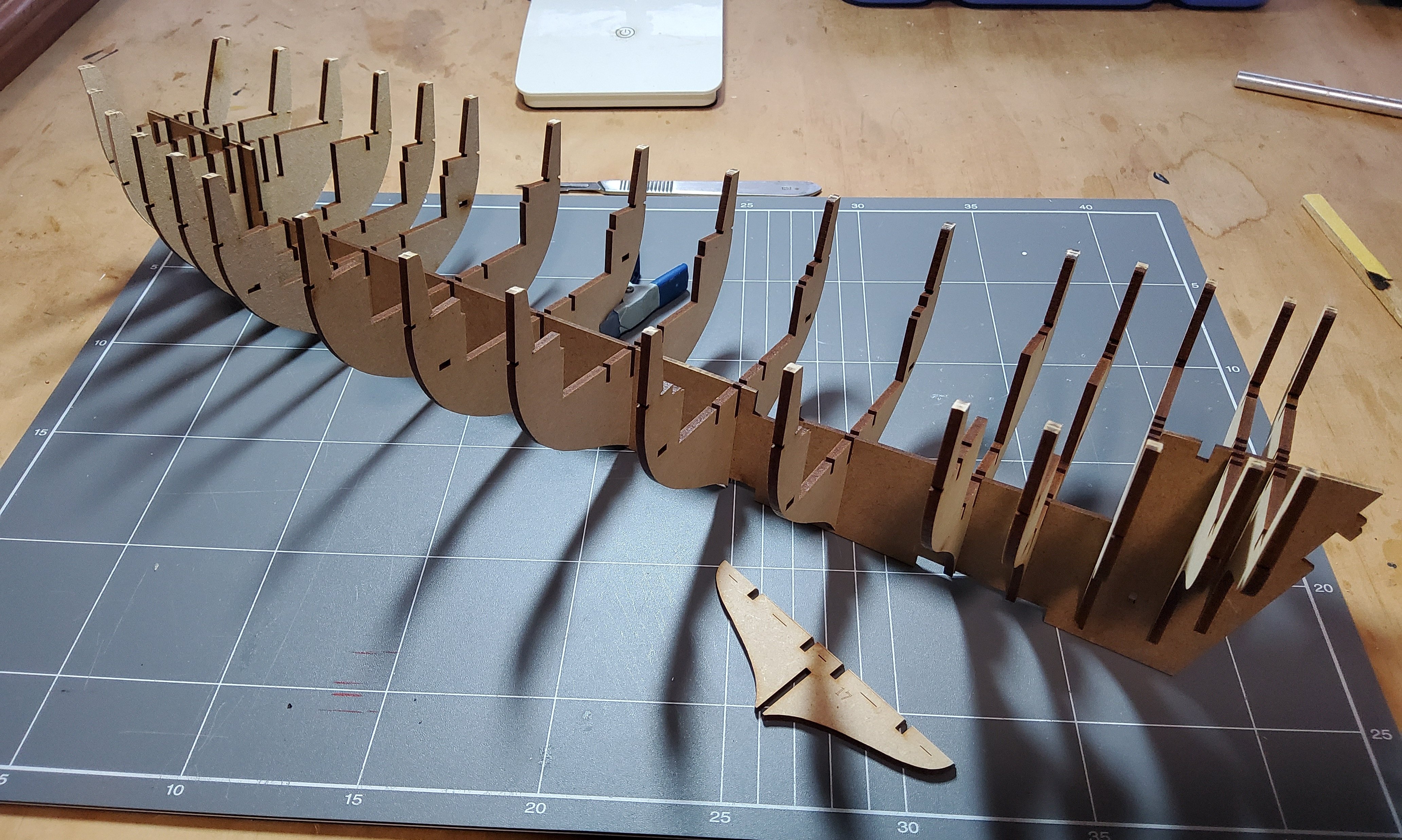
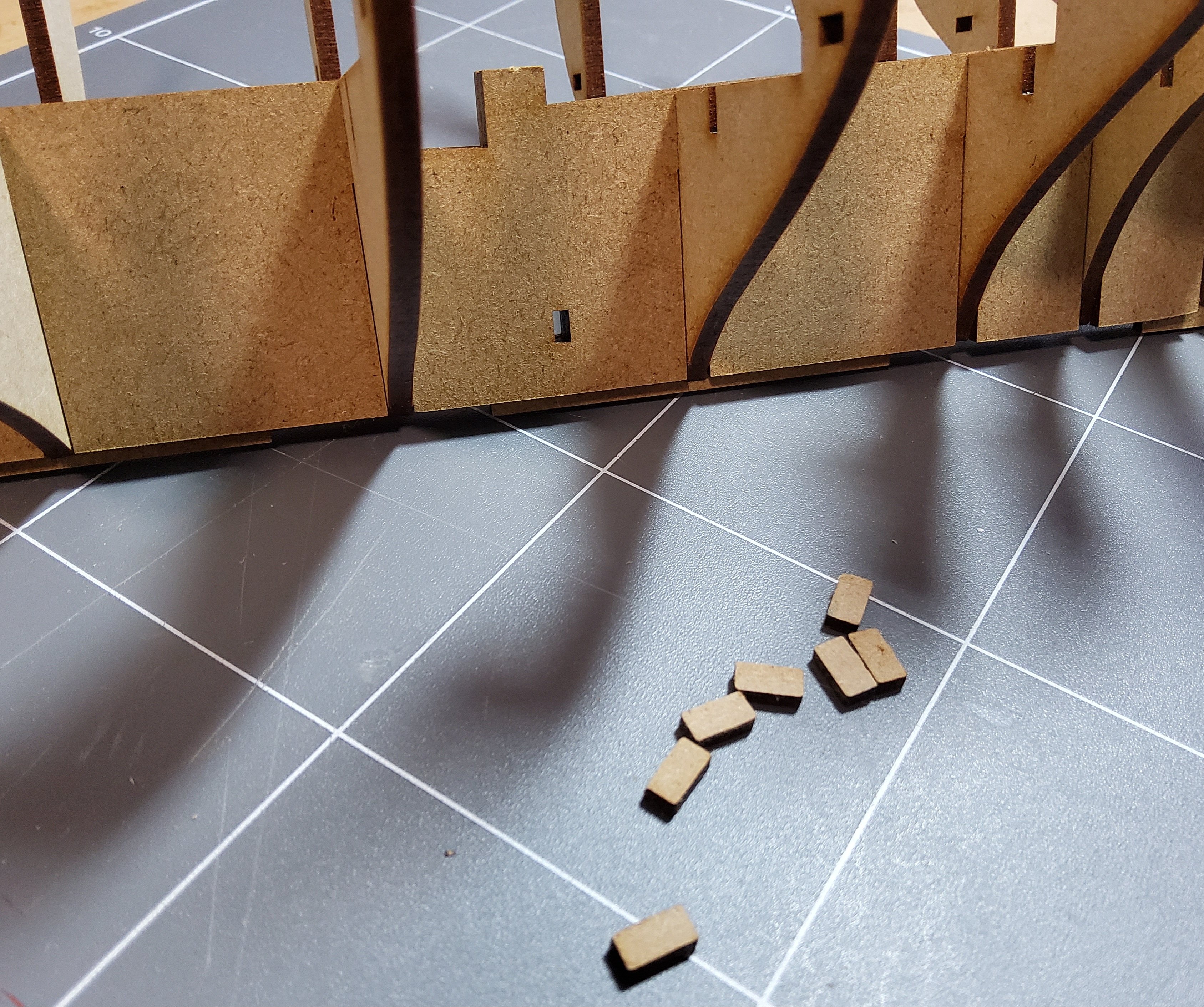
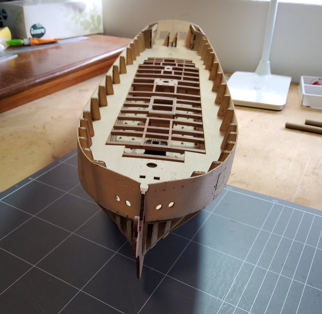
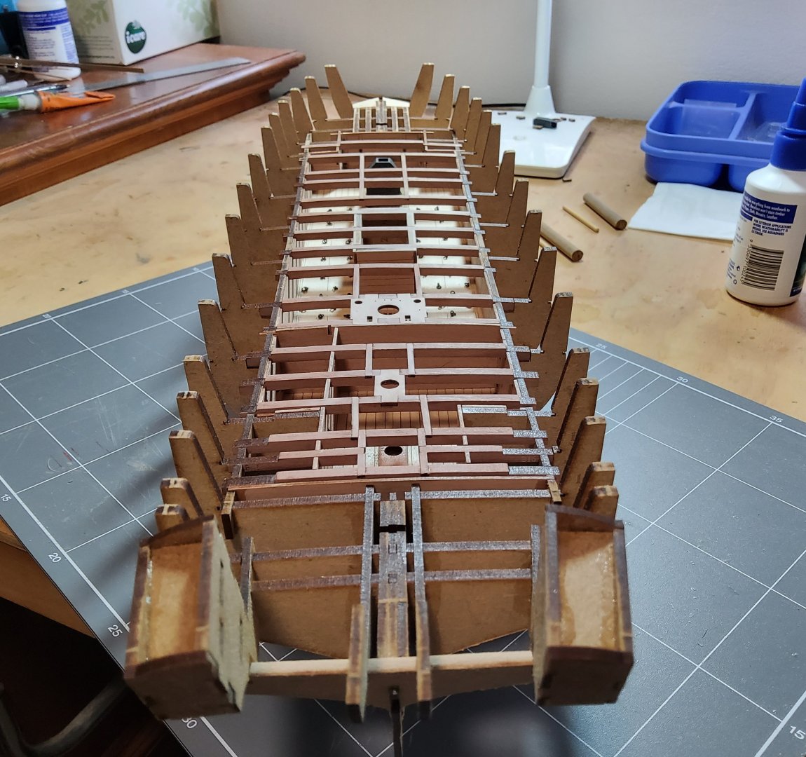
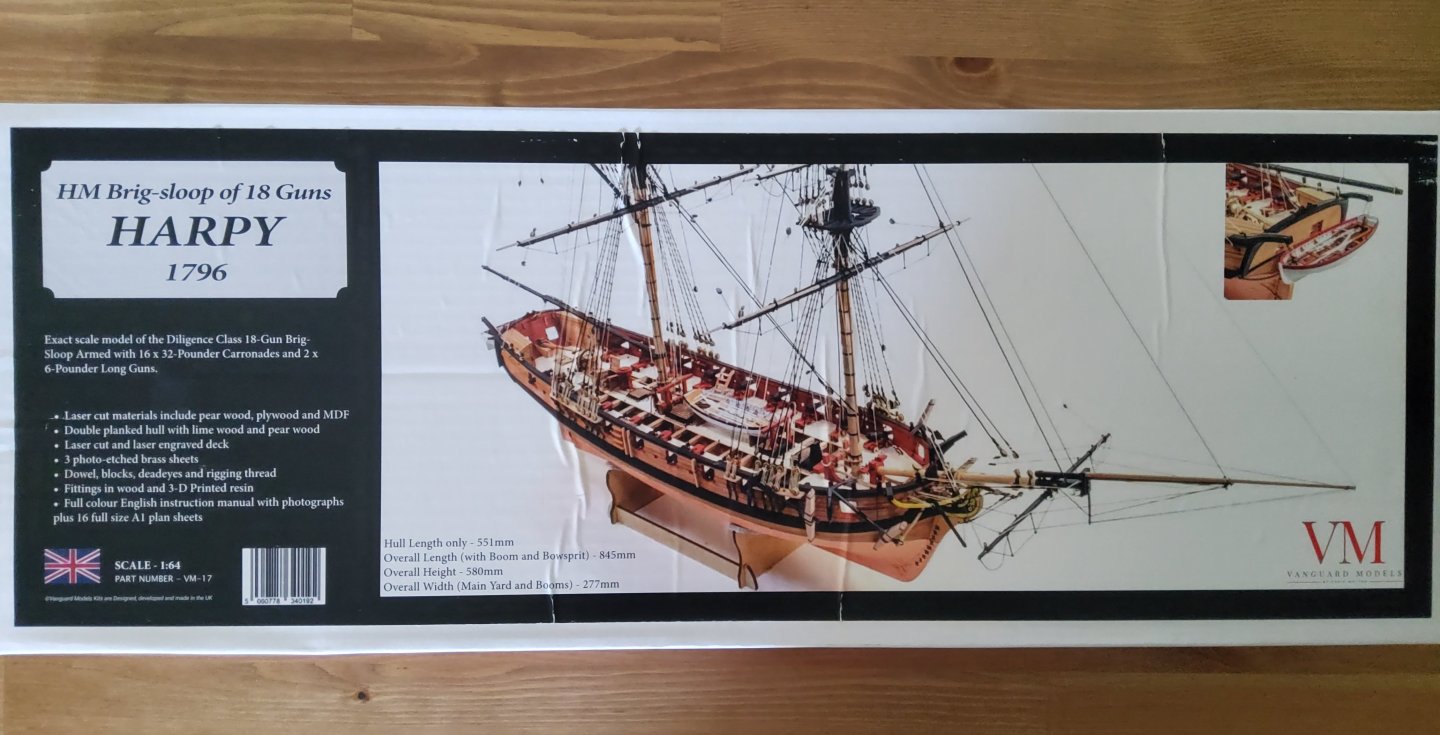
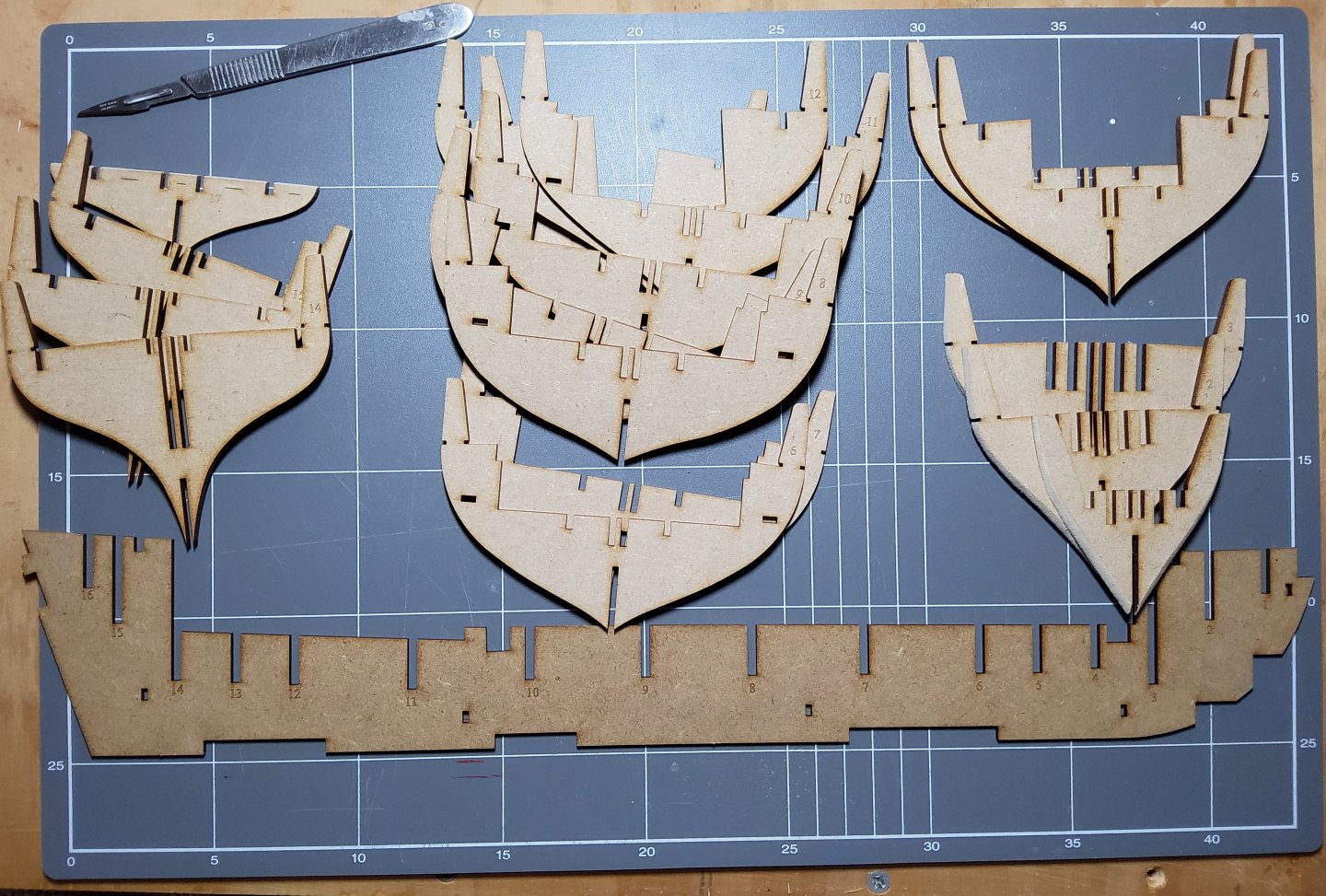
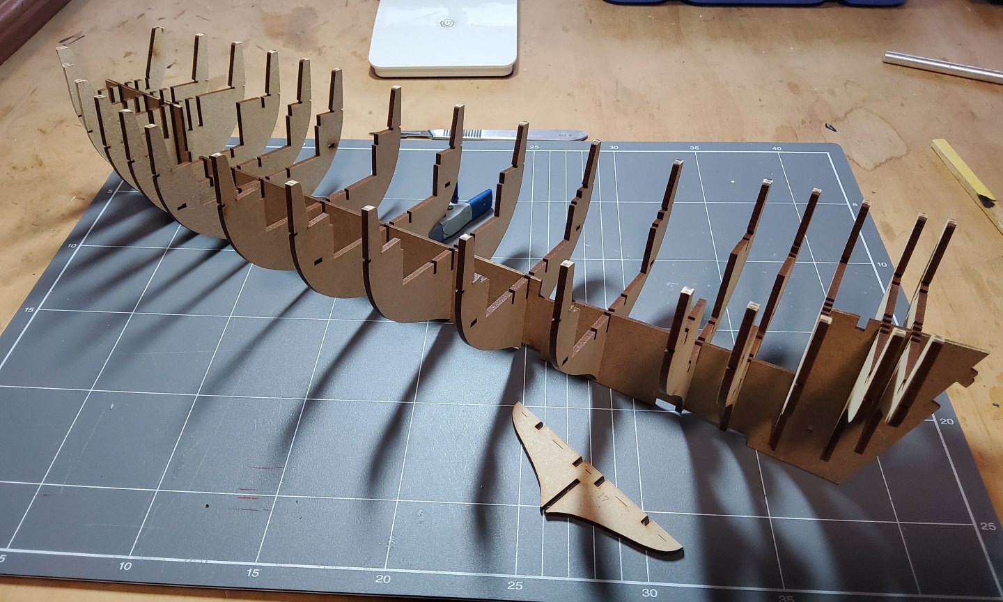
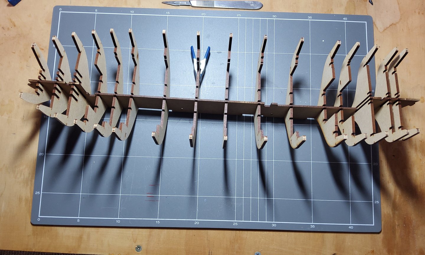
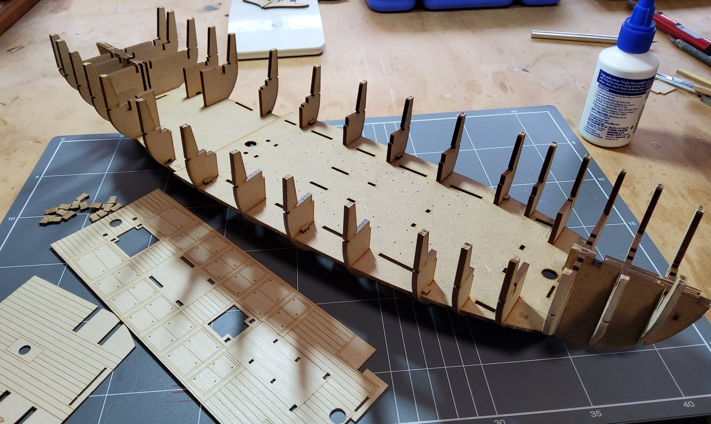
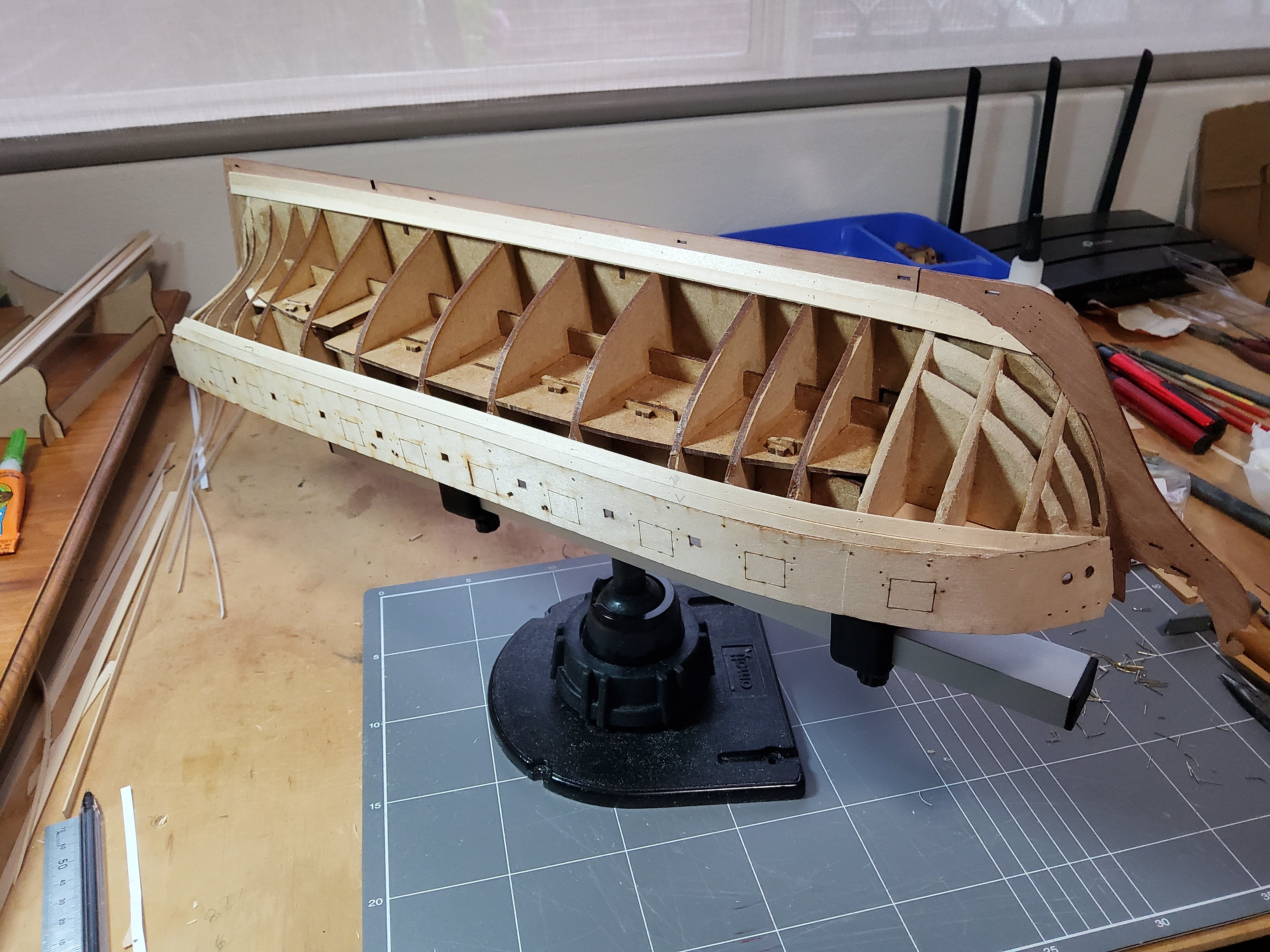
After quite a break, I'm back building a wooden (instead of card) ship, specifically Vanguard’s brig-sloop Harpy. To me it's an attractive vessel, only two masts so not too many ratlines, 18 guns only and of a size that I can accommodate. Also of course the designer, Chris Watton, has introduced many innovations to his kits, and it will be interesting to see what awaits. Before buying the kit, I read James's prototype build and thought I can handle that, so the kit was ordered. Two weeks to Australia, which was very good considering that this was over Christmas/New Year. I'm not going to describe the kit's contents as James has done so in detail. So onto the build. The first photo shows the bulkheads and the false keel. Four bulkheads (1,2,3 and 17) needed chamfering before assembly, and this was aided by them having a laser etched line to guide this. Five minutes after that photo and this is the result. Bulkhead 17 is put in place sometime later. All bulkheads fitted onto the false keel with little pressure needed, except for No3, which wouldn't quite go. A gentle pass with a file fixed that, only the char needed removing. Chris’ innovations include not using any glue until quite some way along the build, with various parts being held together with pegs. This was done with the keel doublers, one on each side of the false keel, with the pegs going through all three pieces. The pegs for this were a little tight and needed a gentle touch with a sanding stick before inserting. The ply sub-decks were dry-fitted. The etched decks were also dry-fitted to check. No problem, everything fits together so well. Removal of the dry-fitted decks was easy, but here I deviated from the manual which calls for the ply sub-decks and the etched decks to be laminated before final fitting. But first, longitudinal braces were slotted into place and pegged. I know from experience that laminating two largish pieces of wood (or worse, card) can go horribly wrong if the alignment is not spot on, so after test dry-fitting, I decided to first fit the ply sub-decks to the hull then glue the etched decks to these as alignment would be easier. The fore deck is held in place with pegs and then the etched deck was glued to it. The aft deck needed to be glued in place first as the pegs that should have been used are designed to hold the laminated deck in place, not just the ply sub-deck. Cheers


.jpg.b41c981bdcaf745719af5e24e932efdd.jpg)