Richard44
-
Posts
409 -
Joined
-
Last visited
3 Followers


-
 Richard44 reacted to a post in a topic:
HMS Harpy 1796 by dunnock - Vanguard Models - 1:64
Richard44 reacted to a post in a topic:
HMS Harpy 1796 by dunnock - Vanguard Models - 1:64
-
Richard44 reacted to a post in a topic:
Oryol 1902 by GrandpaPhil - Orel - 1/200 - CARD - Russian Battleship
-
Richard44 reacted to a post in a topic:
Herzogin Cecilie 1902 by Jim Lad - Four Masted Barque
-
Richard44 reacted to a post in a topic:
Oryol 1902 by GrandpaPhil - Orel - 1/200 - CARD - Russian Battleship
-
Richard44 reacted to a post in a topic:
PHOENIX 1787 by ccoyle - Master Korabel - 1/72 - Russian brigantine of the Black Sea Fleet
-
Richard44 reacted to a post in a topic:
HMS Harpy 1796 by Glenn-UK – Vanguard Models - 1:64 scale
-
Richard44 reacted to a post in a topic:
HMS Harpy 1796 by dunnock - Vanguard Models - 1:64
-
Richard44 reacted to a post in a topic:
PHOENIX 1787 by ccoyle - Master Korabel - 1/72 - Russian brigantine of the Black Sea Fleet
-
Richard44 reacted to a post in a topic:
USS Baltimore CA-3 1890 by Jsk - FINISHED - Heinkel Models - Scale 1/200 - CARD
-
Richard44 reacted to a post in a topic:
PHOENIX 1787 by ccoyle - Master Korabel - 1/72 - Russian brigantine of the Black Sea Fleet
-
davyboy reacted to a post in a topic:
HMS Harpy 1796 by Richard44 - Vanguard Models - 1:64
-
davyboy reacted to a post in a topic:
HMS Harpy 1796 by Richard44 - Vanguard Models - 1:64
-
davyboy reacted to a post in a topic:
HMS Harpy 1796 by Richard44 - Vanguard Models - 1:64
-
Craigie65 reacted to a post in a topic:
HMS Harpy 1796 by Richard44 - Vanguard Models - 1:64
-
hollowneck reacted to a post in a topic:
HMS Harpy 1796 by Richard44 - Vanguard Models - 1:64
-
hollowneck reacted to a post in a topic:
HMS Harpy 1796 by Richard44 - Vanguard Models - 1:64
-
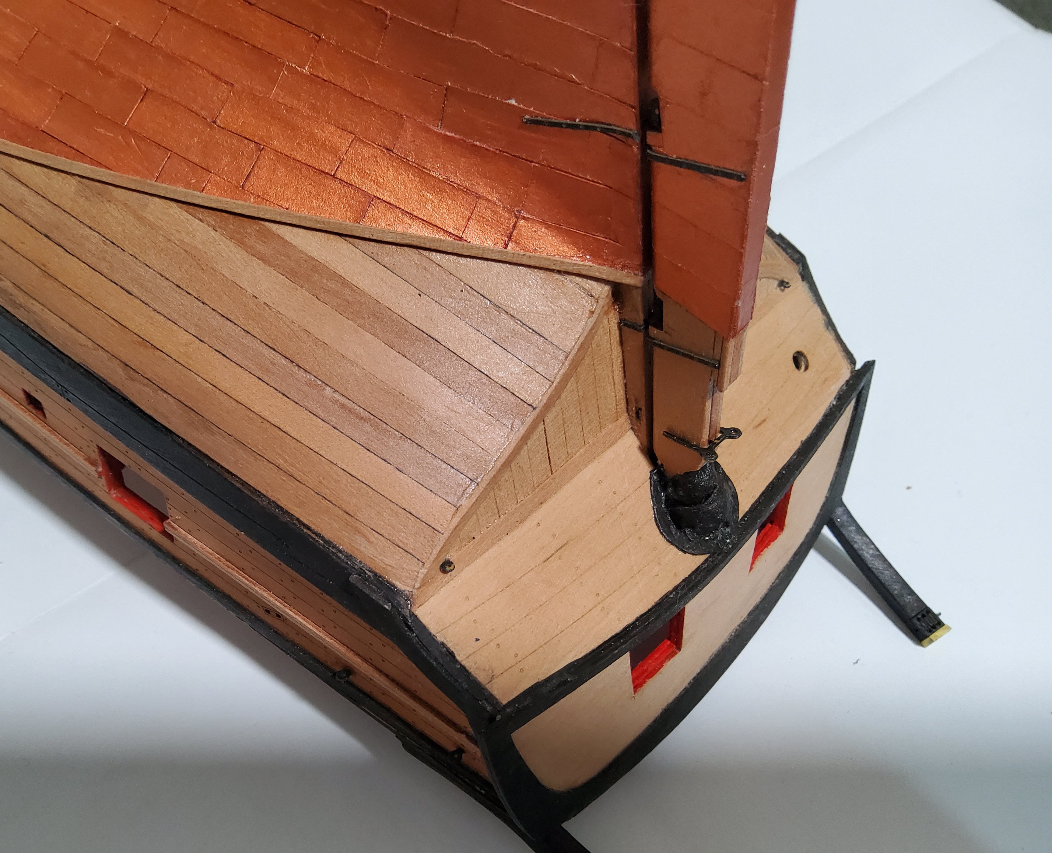
 Forgot about the chimney, easily fixed though.
 -
rcweir reacted to a post in a topic:
HMS Harpy 1796 by Richard44 - Vanguard Models - 1:64
-
Glenn-UK reacted to a post in a topic:
HMS Harpy 1796 by Richard44 - Vanguard Models - 1:64
-
AJohnson reacted to a post in a topic:
HMS Harpy 1796 by Richard44 - Vanguard Models - 1:64
-
AJohnson reacted to a post in a topic:
HMS Harpy 1796 by Richard44 - Vanguard Models - 1:64
-
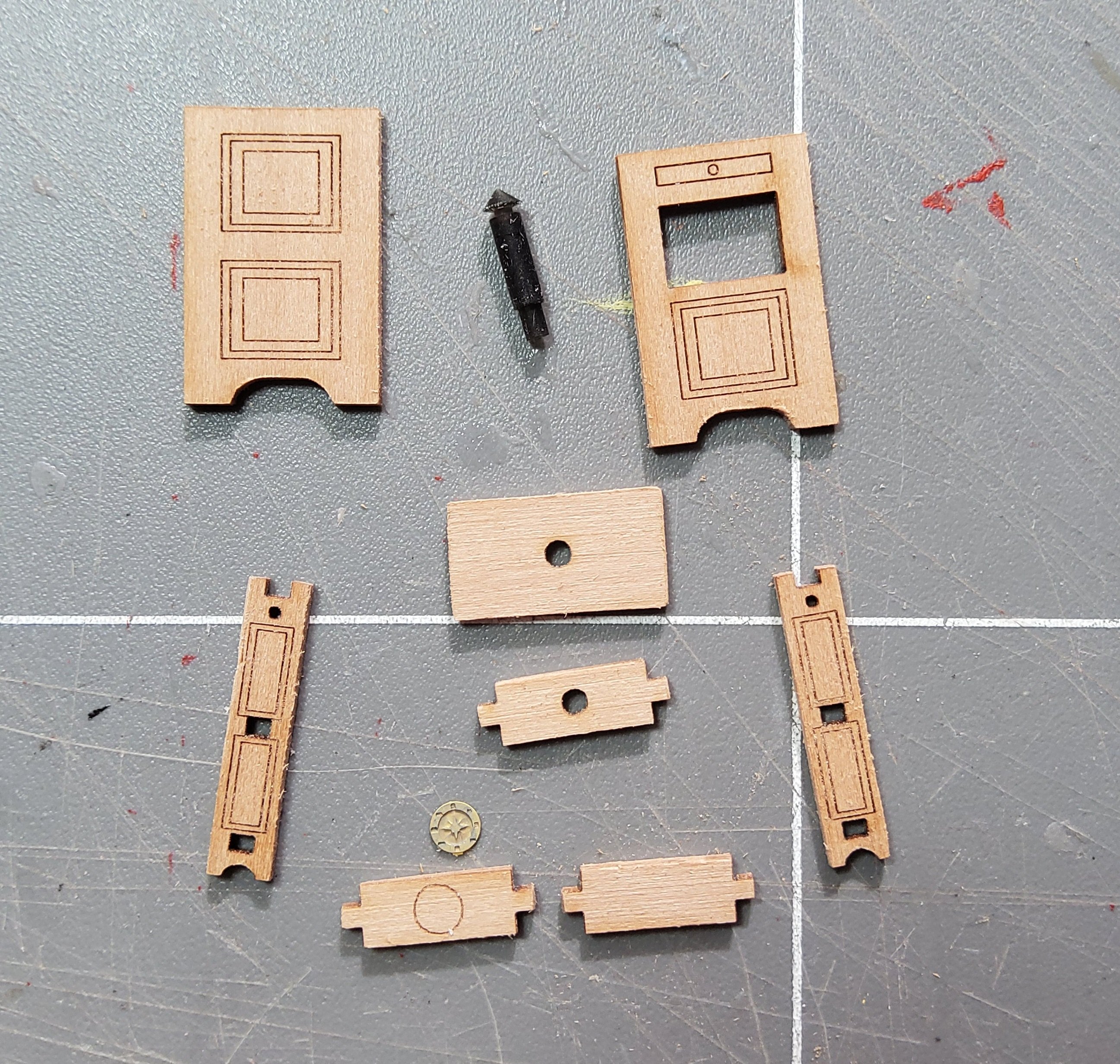
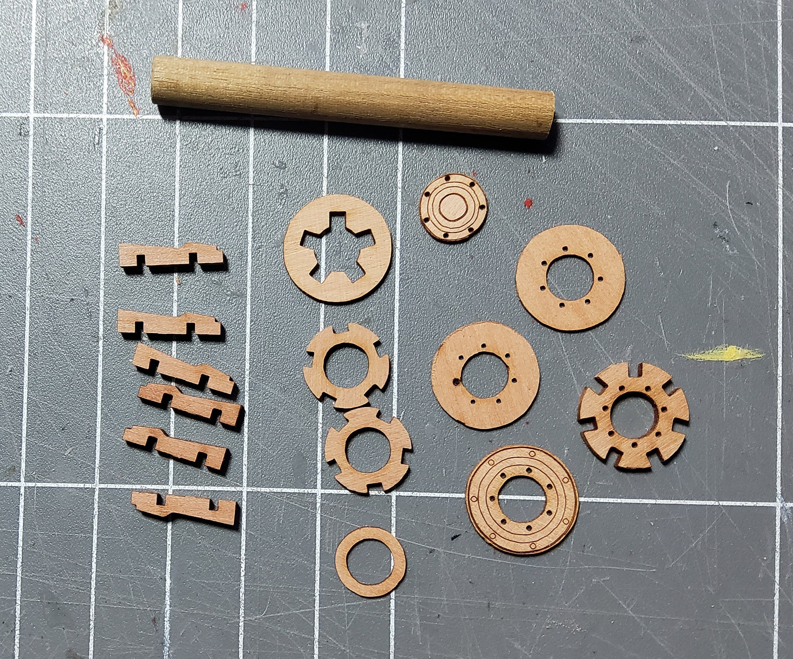
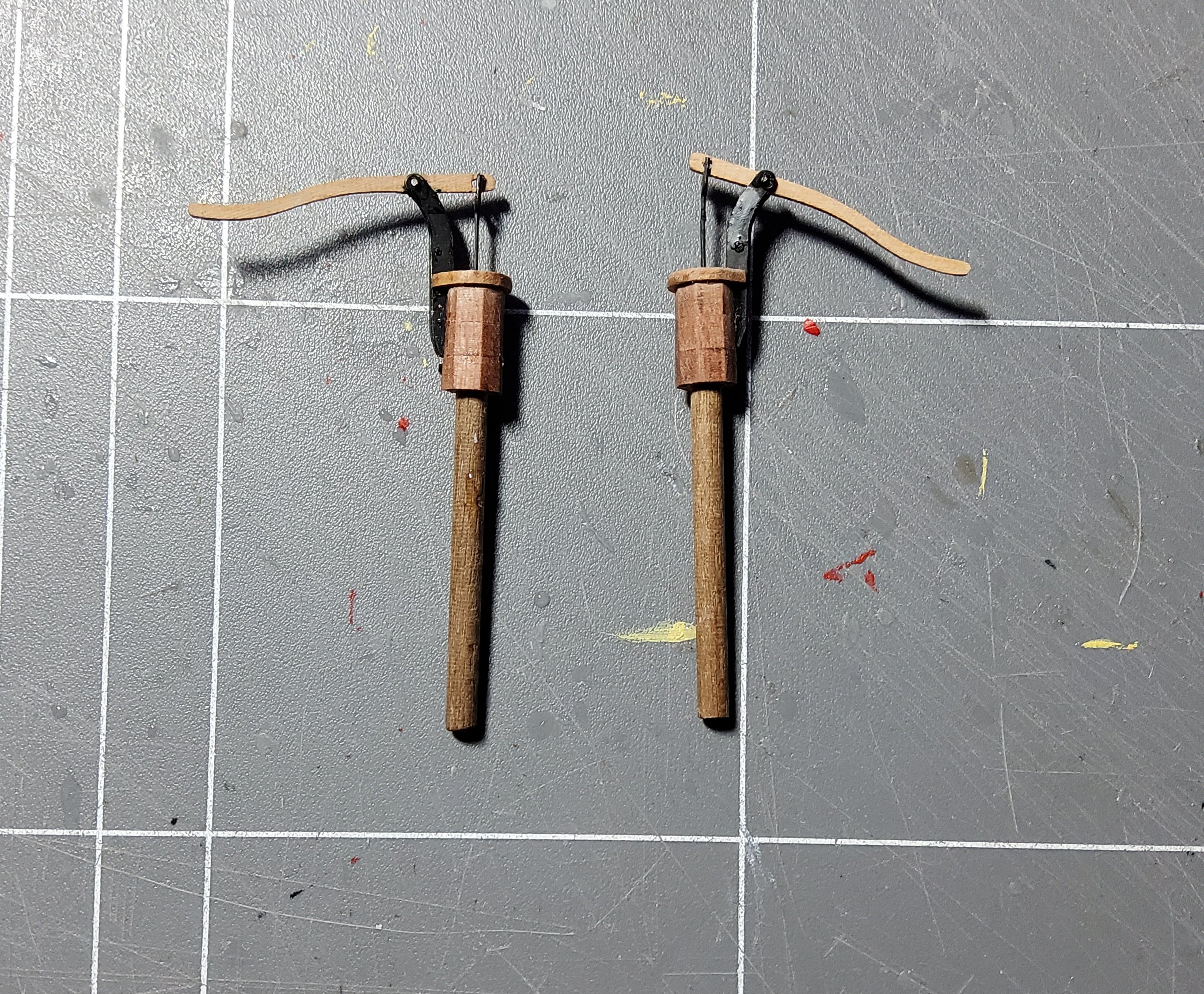
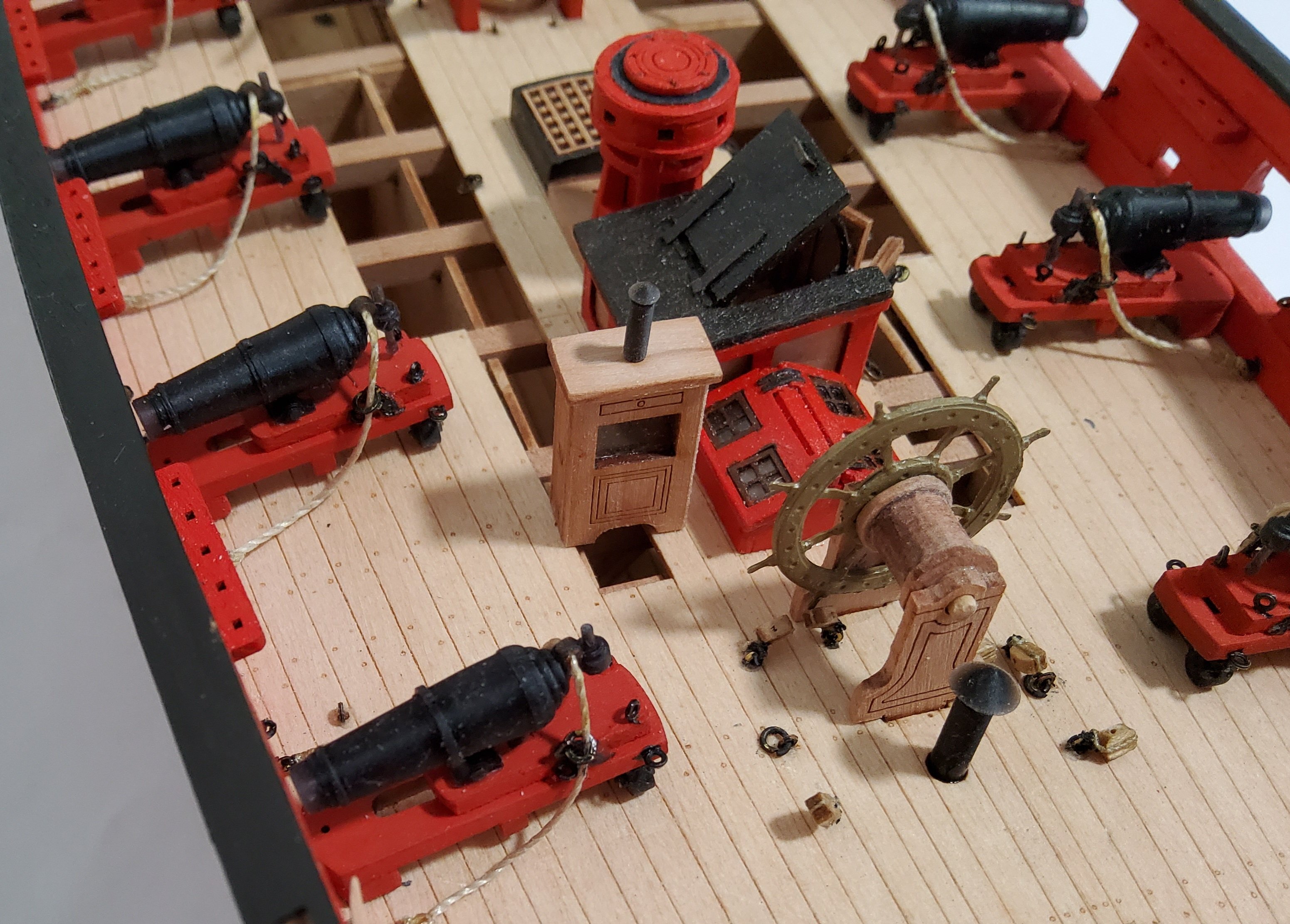
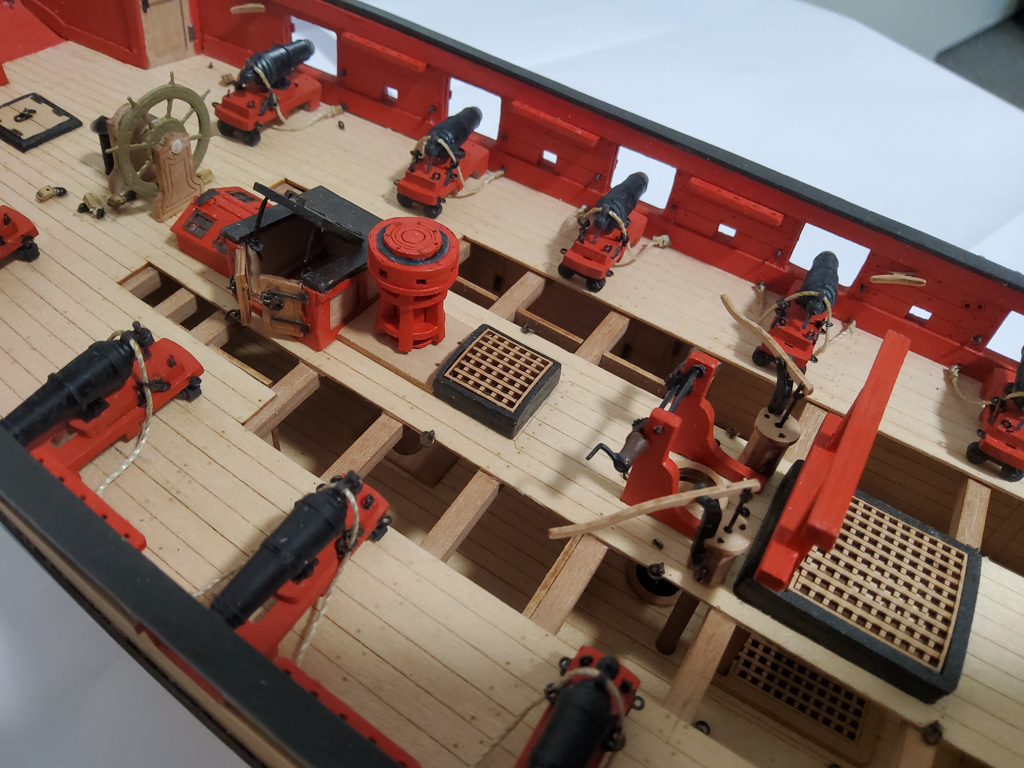
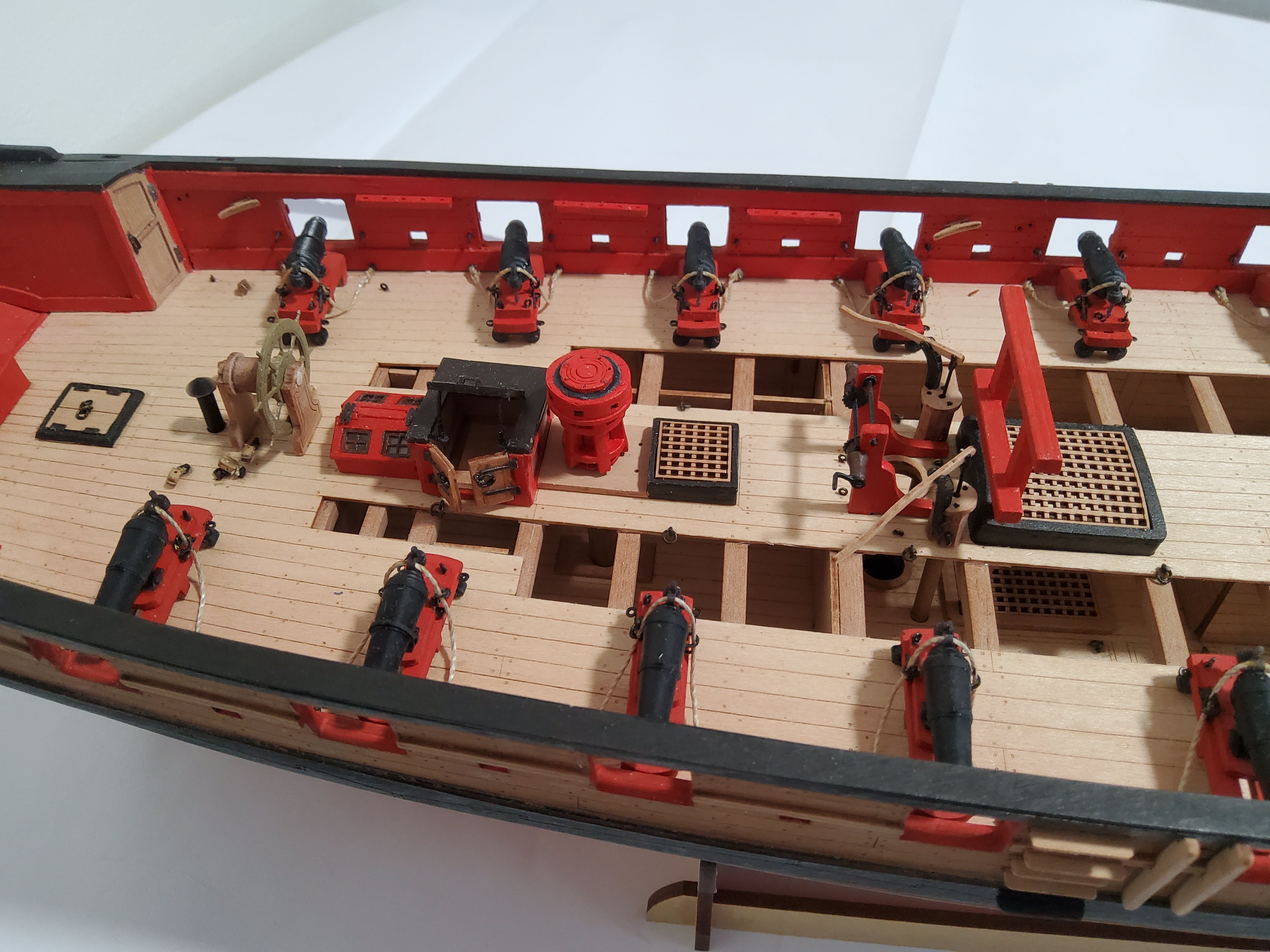
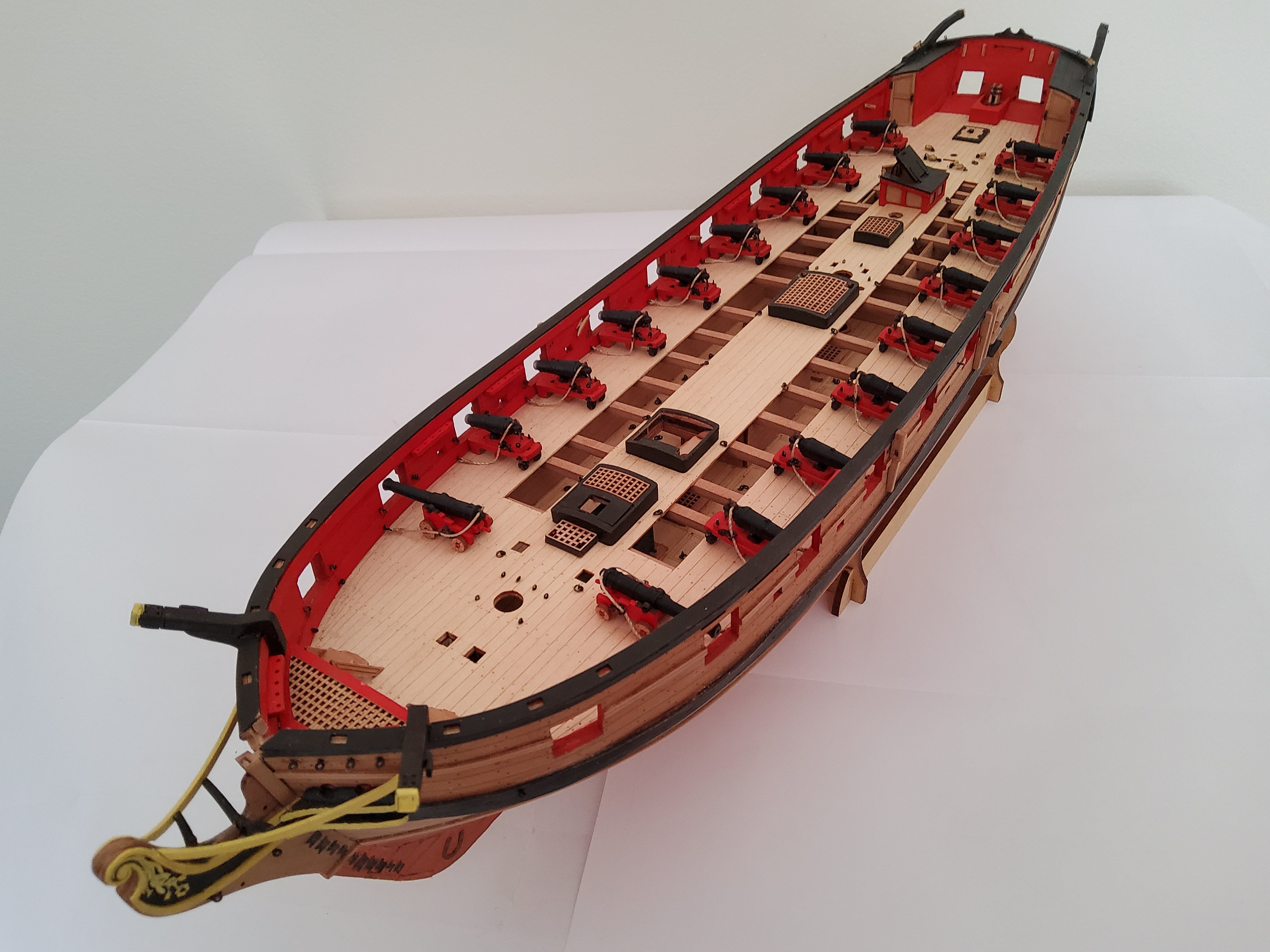
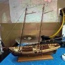
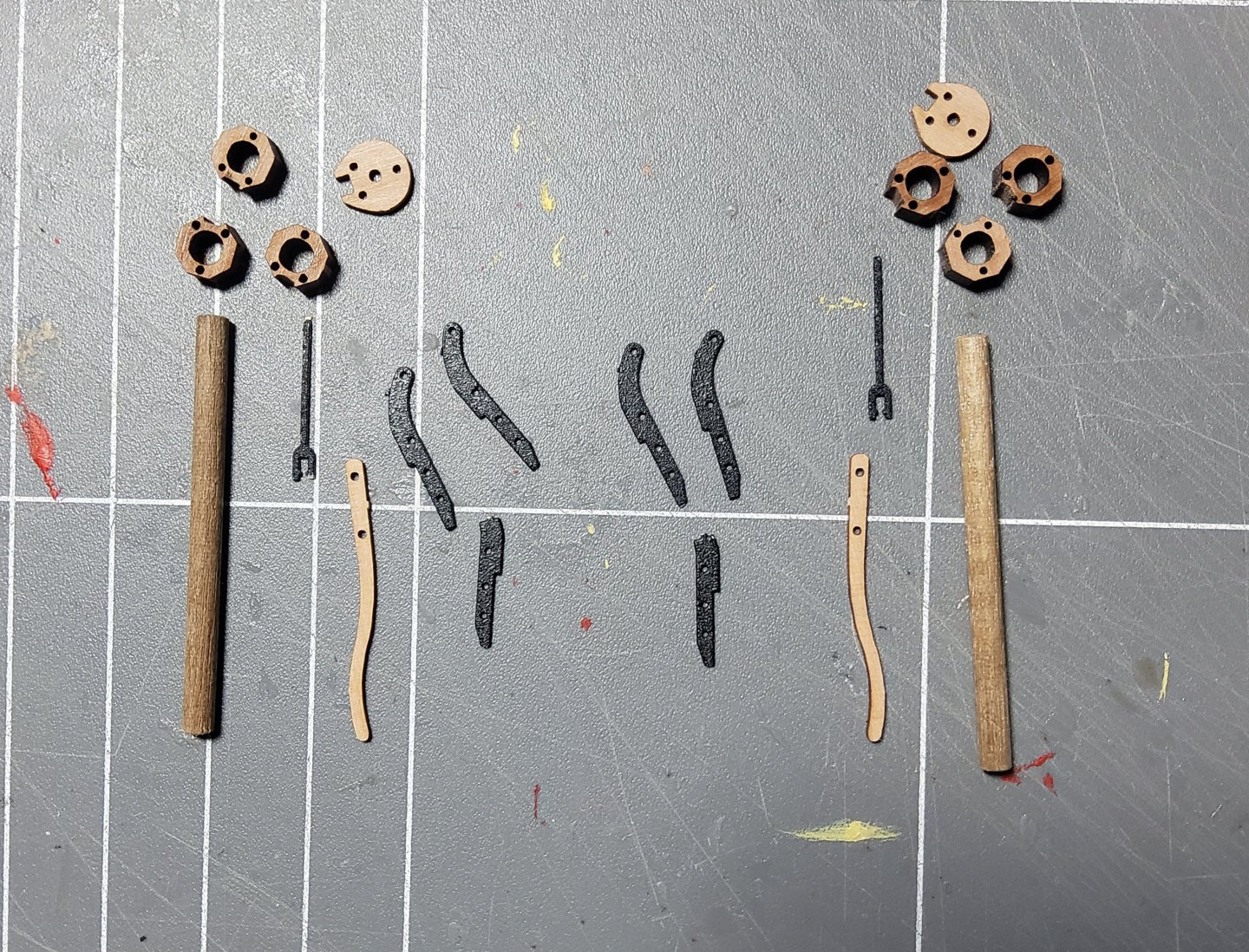
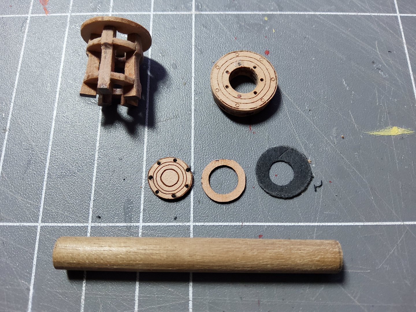
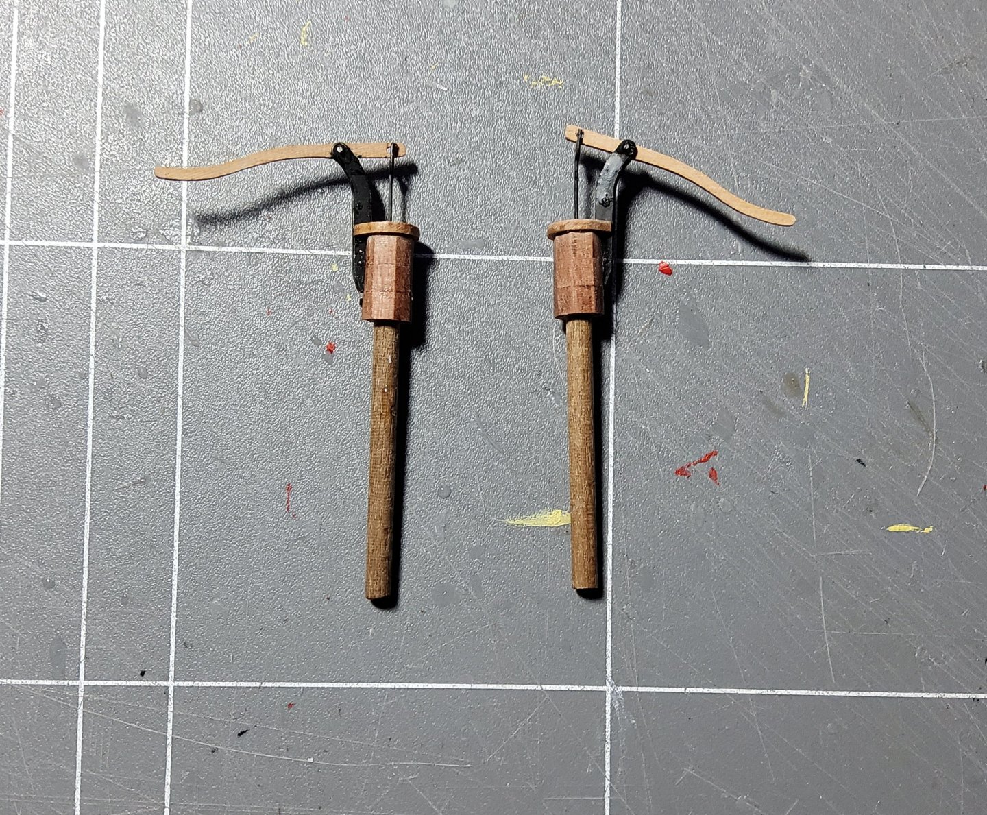
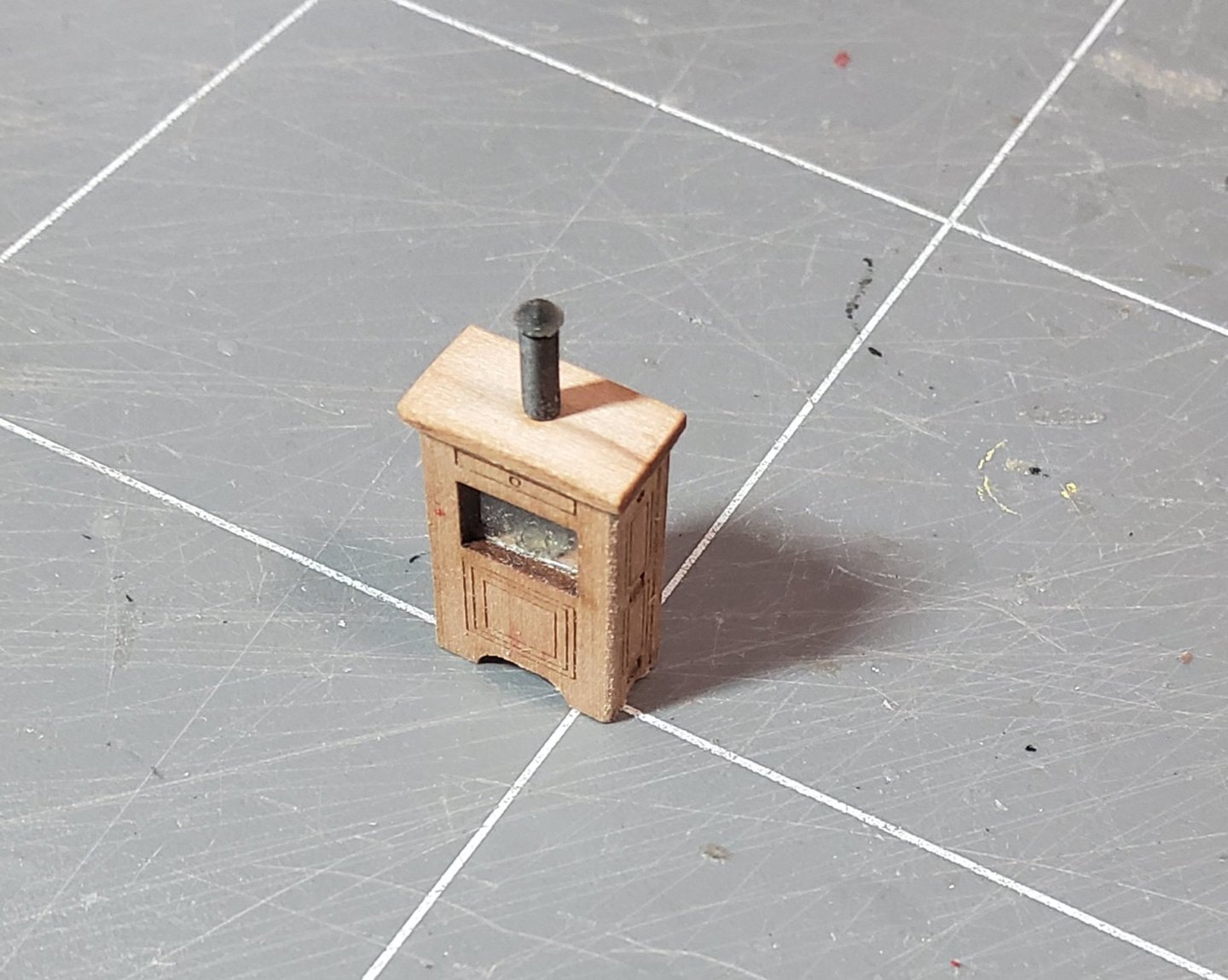
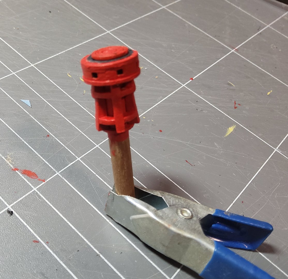
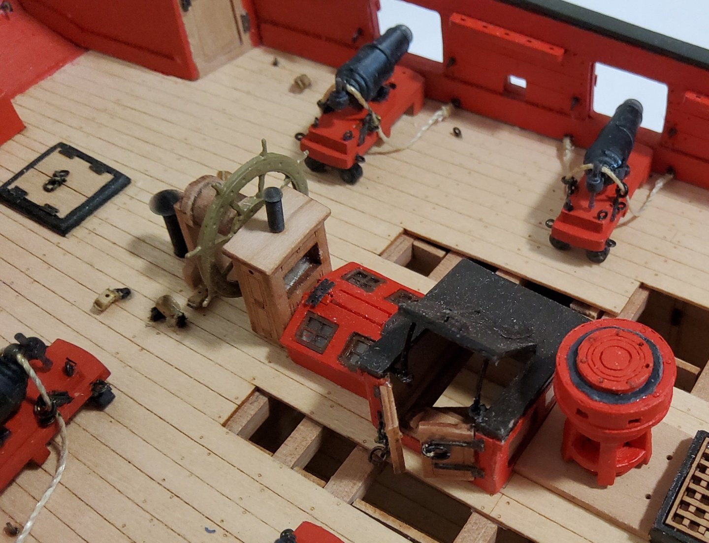
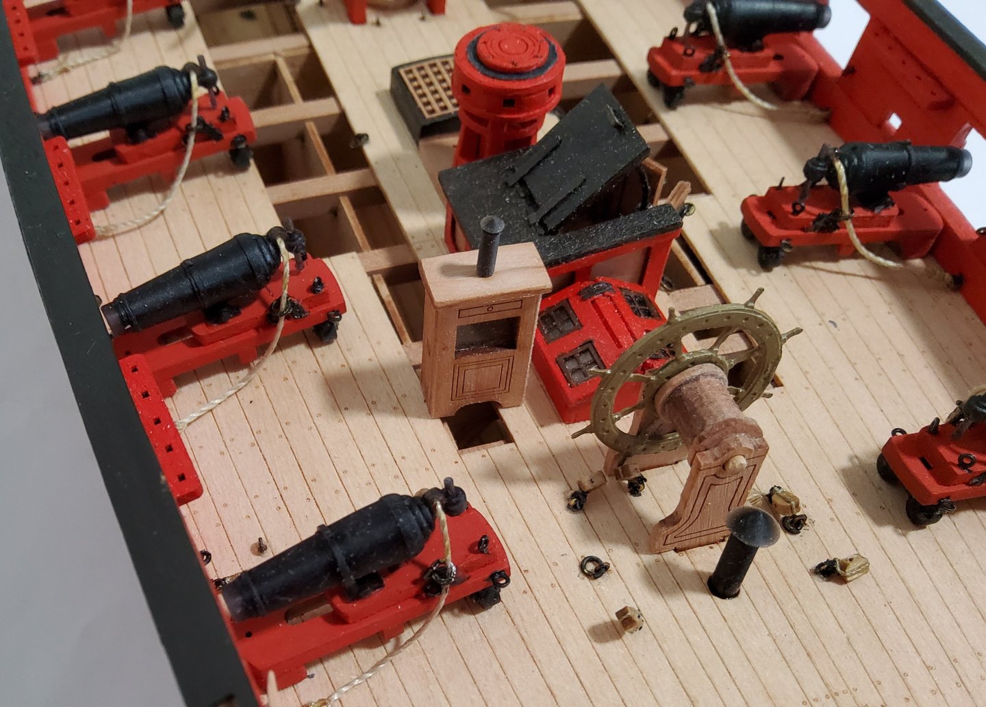
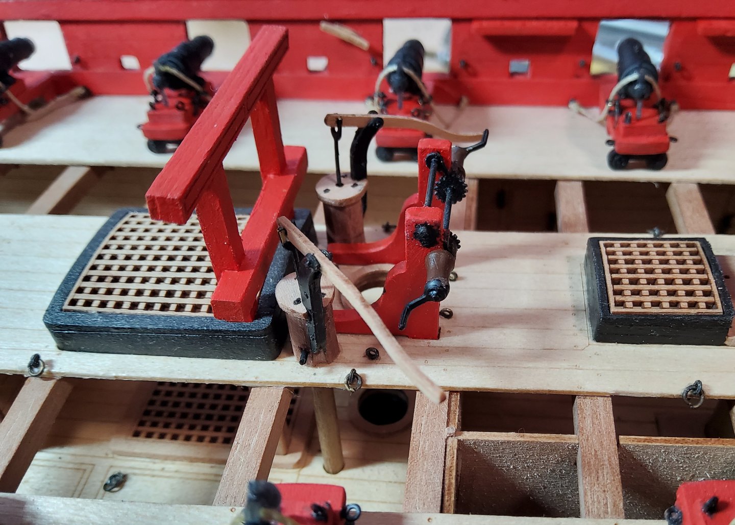
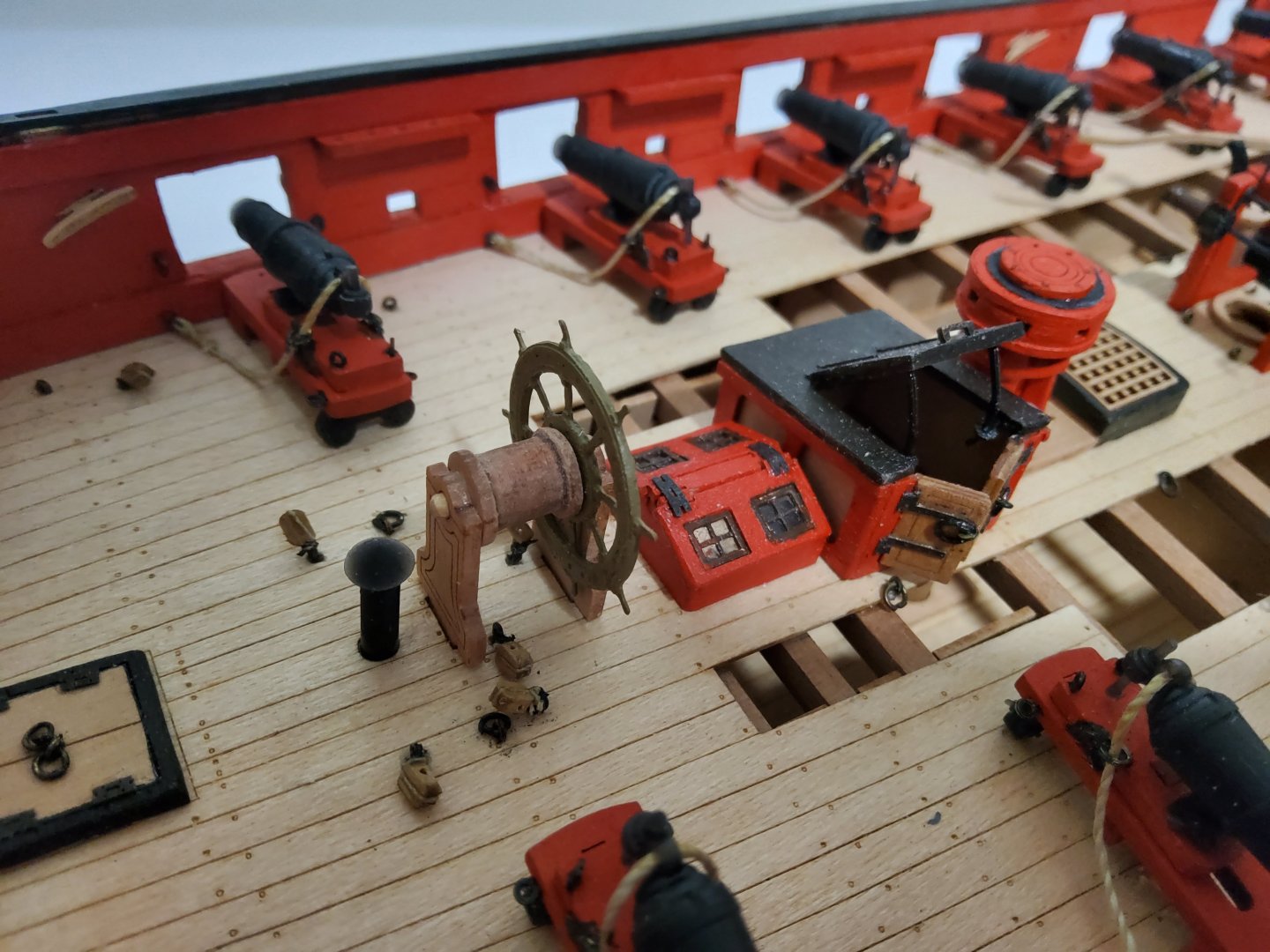
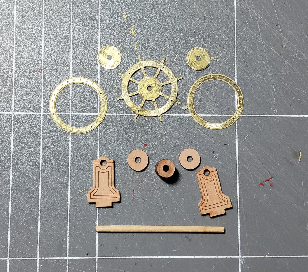
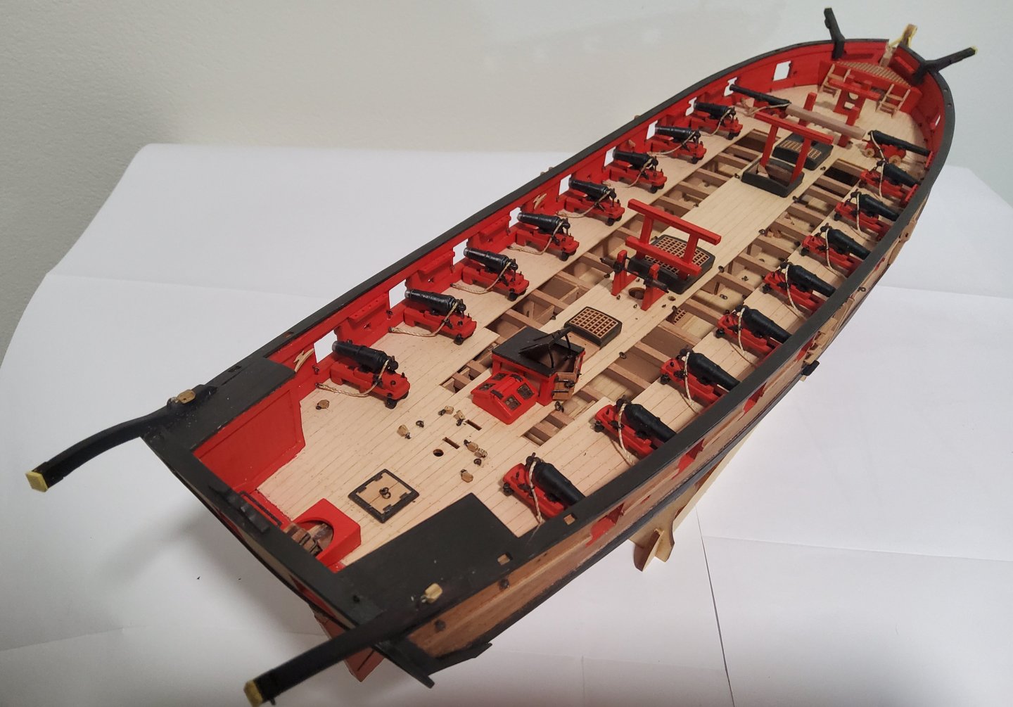
More deck fittings. The two pumps were the first to be done. Parts for the pumps are shown below. The body is hexagonal and made up of three pieces that need to be glued together. The manual says to use a length of dowel to keep the pieces correctly aligned, but also says don't glue these to the dowel, which is to be removed now and replaced later. After thinking about this and looking at the parts and the order in which they were to be assembled, I decided that gluing the three hexagonal pieces to the dowel at this stage was going to work just fine. The length of dowel required (it goes all the way down through the lower deck) was carefully checked first. The top to the body was glued in place and brass pins pushed into the provided holes, representing bolts that hold the body of the pump together. Three brass pieces were glued together with gel CA, with three brass pins providing alignment. The heads of the pins were ground off and the pins trimmed. This stanchion provides the pivot point for the handle, and a pin was pushed through it and the handle. A drop of gel CA was applied at each end of the pin to keep it in place, and it was later trimmed. The pump operating rod was loosely attached to the handle and it extends down into the pump body. As I had the dowel extending right to the top of the pump body, I had to drill a clearance hole to allow the rod to be insered. The pumps almost complete, and completed. Next the capstan. Parts are shown below. As with the pumps, some parts need to be assembled using a dowel to ensure alignment, with the manual saying do not glue the parts to the dowel. The capstan partly assembled. And completed. A piece of black card was used to represent the iron reinforcing ring on top of the drum. The wheel was next, nothing difficult to this. Parts are below and I forgot to take a photo of the assembled fitting. Next the difficult fitting. Not difficult to build, but positioning it is tricky. The binnacle. The parts are below and the finished binnacle below that. I glazed the opening through which the compass could be seen, with a piece of plastic. But where to put it. The manual has it jammed between the wheel and the skylight and facing forward, a position that means the helmsman cannot possibly see the compass. Blue Ensign in his build log has gone into some detail about this. I will probably position the binnacle off to one side and slightly forward of the wheel. Some photos of Harpy with most deck fittings now in place. Cheers


-
Thanks Andrew, much appreciated.
-
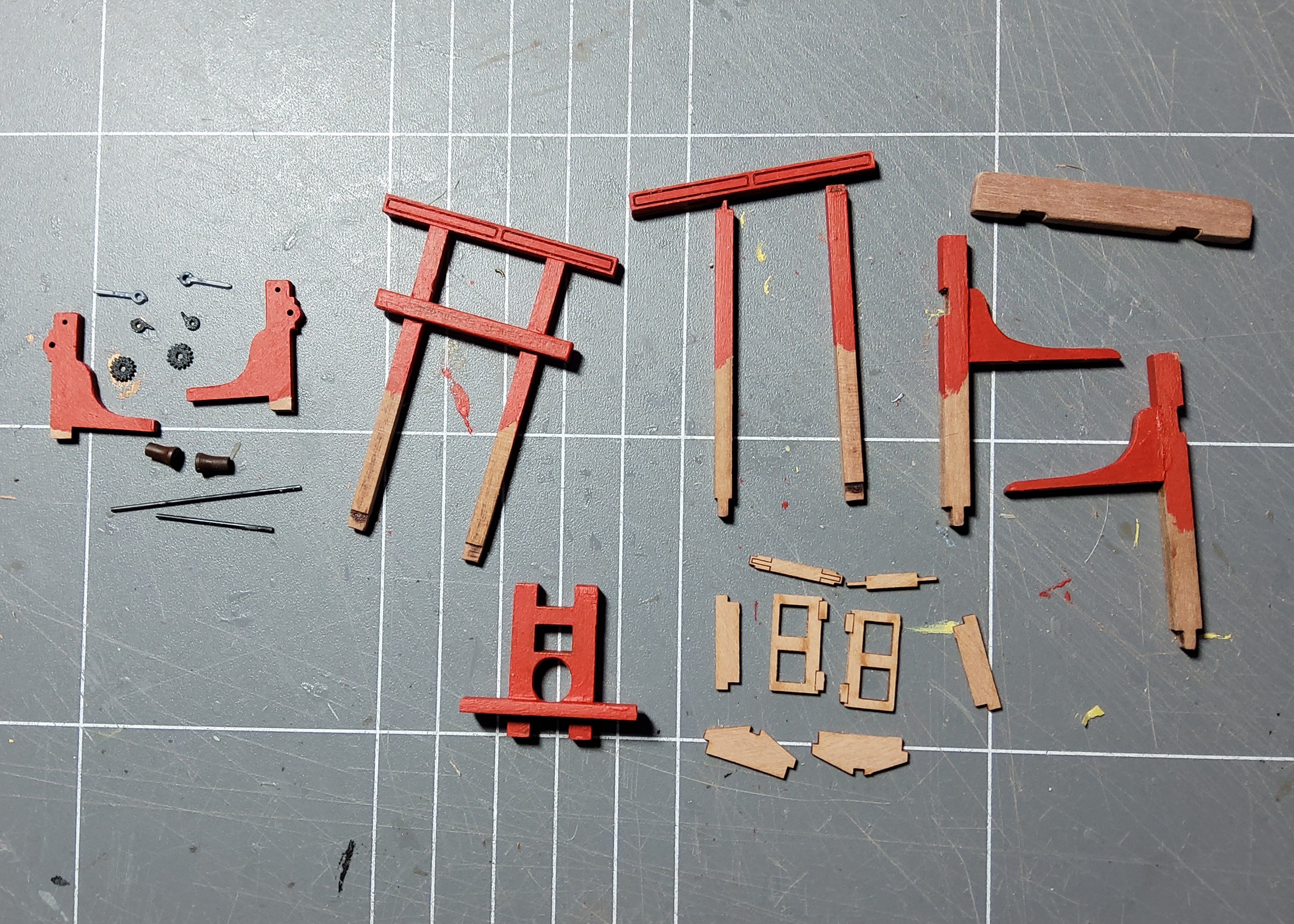
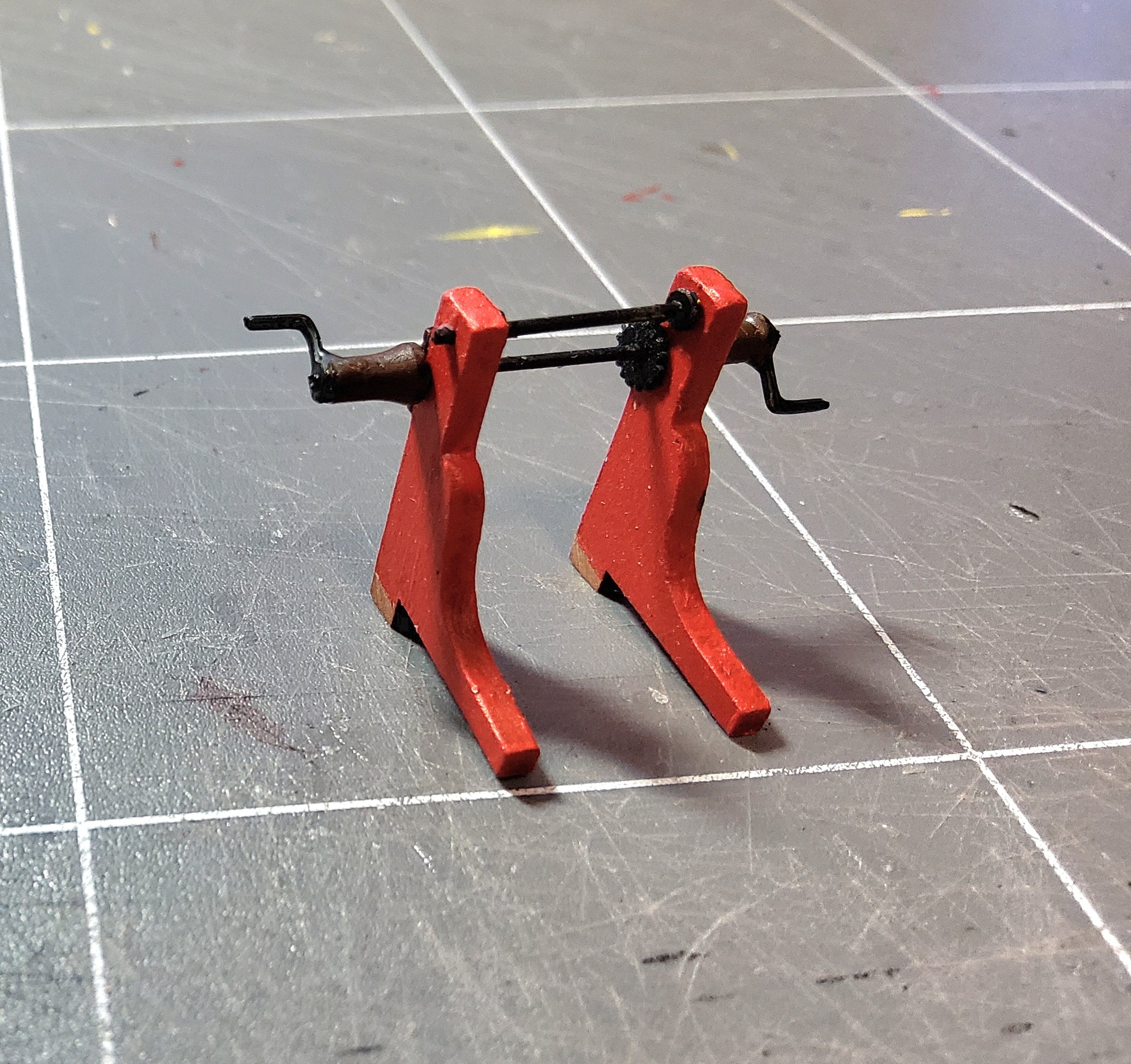
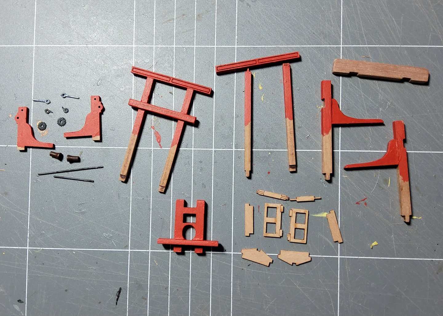
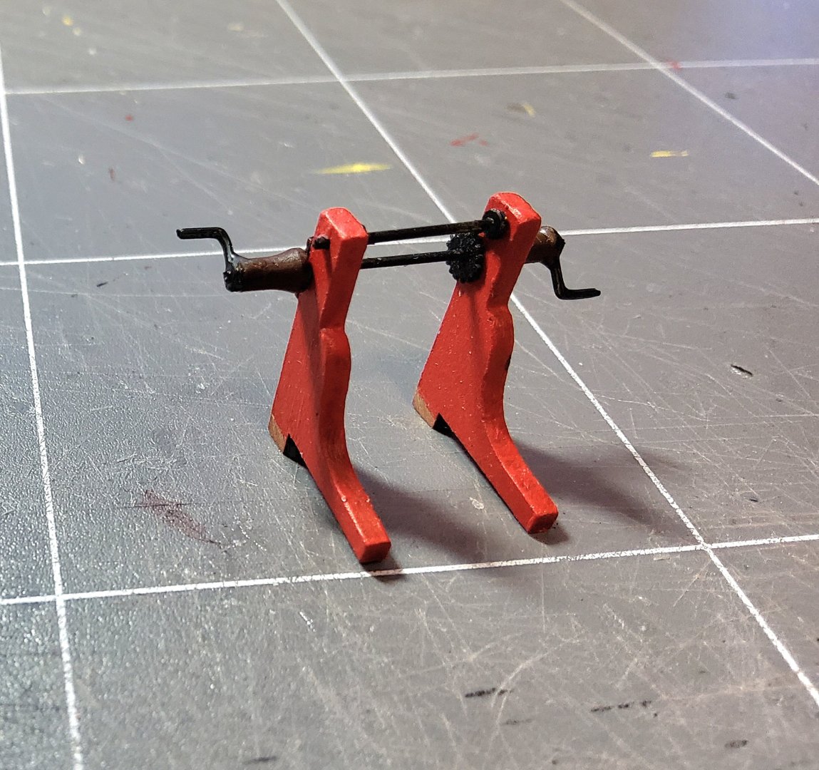
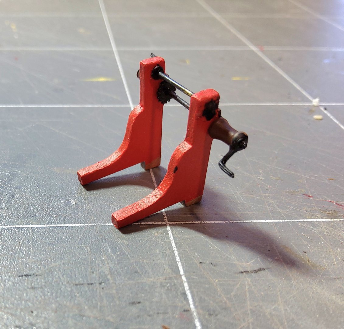
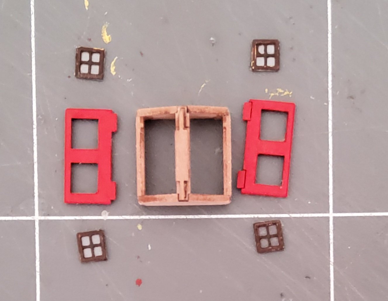
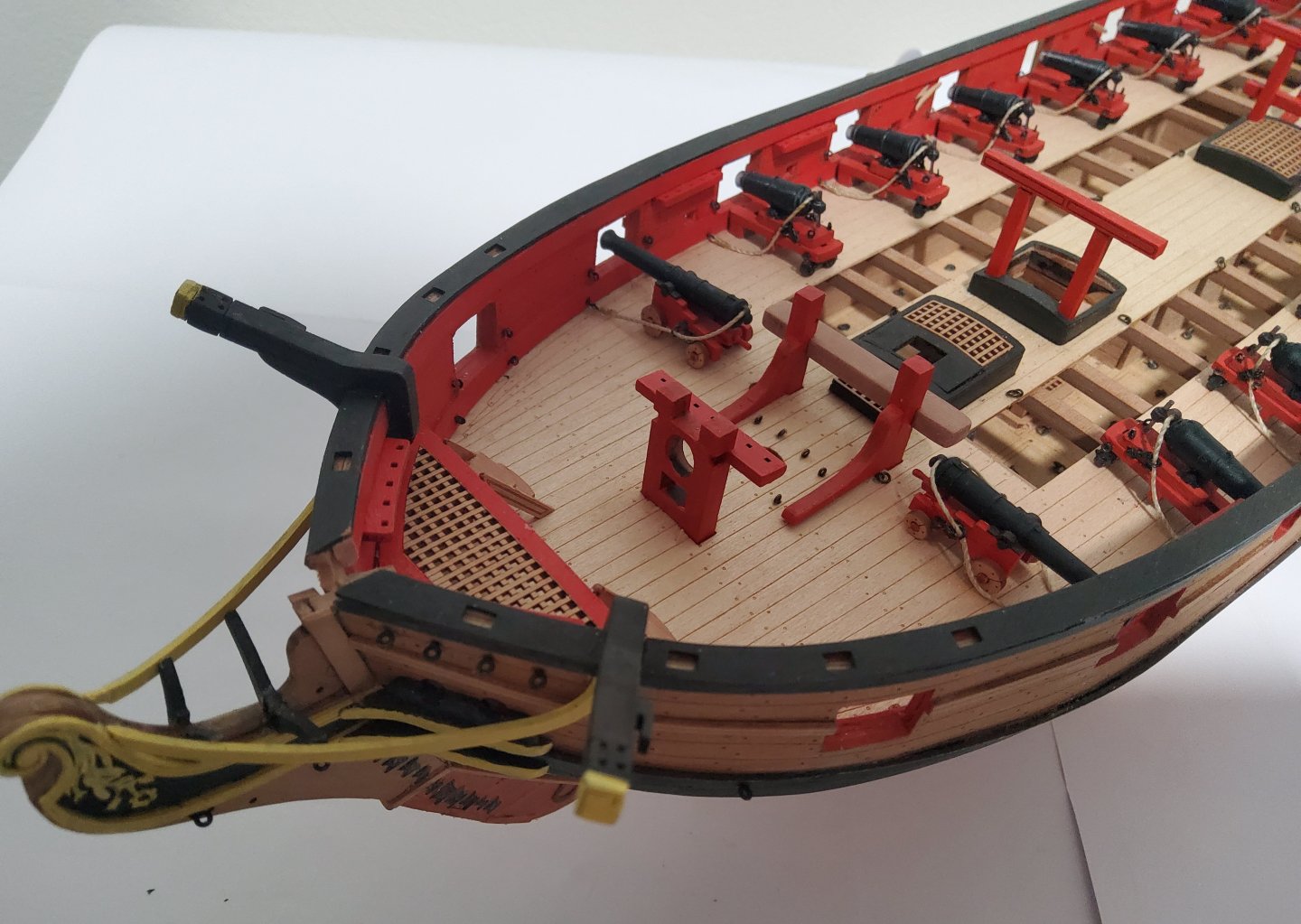
Work proceeds. The photo shows several items, some just from the fret, some partly completed, and others ready for installation. Pieces of the winch are in the top left corner, those for the skylight are in the bottom right corner, there are the two gallows (one complete), the fore bitt and the completed bowspit bitt. Paint has only been applied to the above deck portion of each part. The winch was built partly on the ship, partly off. There are two pices of brass wire required, one 19mm long and the other 32mm long. Both of these are slightly over-long, and if I had simply built the winch off ship, it would not have fitted into the pre-cut slots on the deck. The upper, shorter wire was emplaced in the two side pieces whilst these were fitted into the slots in the deck. These were kept vertical and a small drop of gel CA was applied to the ends of the wire to lock it in place and correctly spaced. This assembly was then removed and the remainder of the parts fitted. Dry fitting of the lower wire was done before final gluing. The ends of the wires were then trimmed. A little bit fiddly, but it turned out quite well. The skylight was done according to the instructions, with the PE window frames painted and backed by clear plastic. These were then pushed into place finishing flush with the outer surface of the skylight hatch. No glue was needed. The photo shows the skylight just before final assembly (the red colour in the photo is a bit off). Some touch up of the paint on the window frames was needed first. The two gallows and the two bitts were easily assembled. All parts now in place on the deck. I have just realised that I have forgotten to add the stove chimney - ah well, a job for tomorrow. Cheers

-
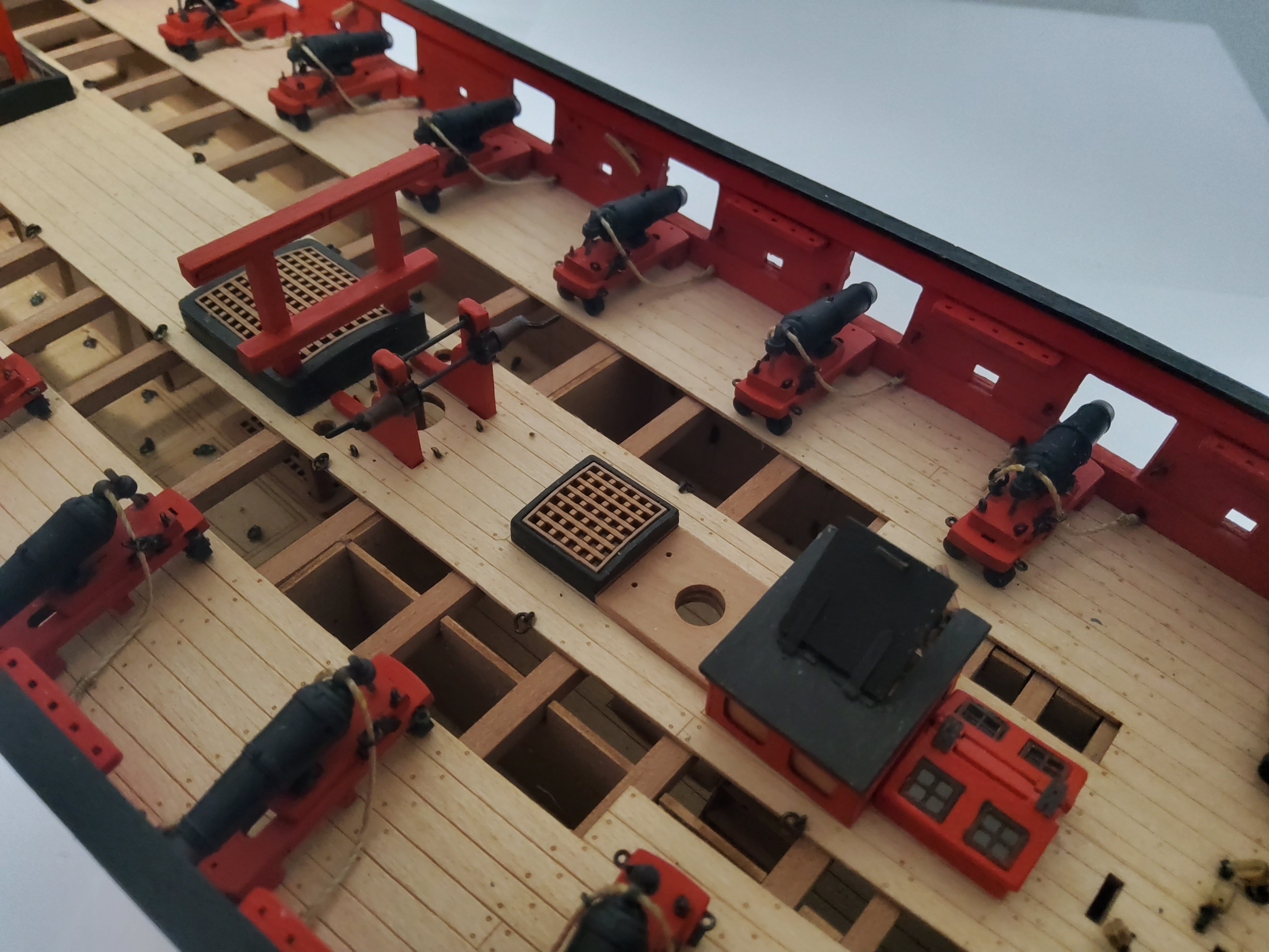
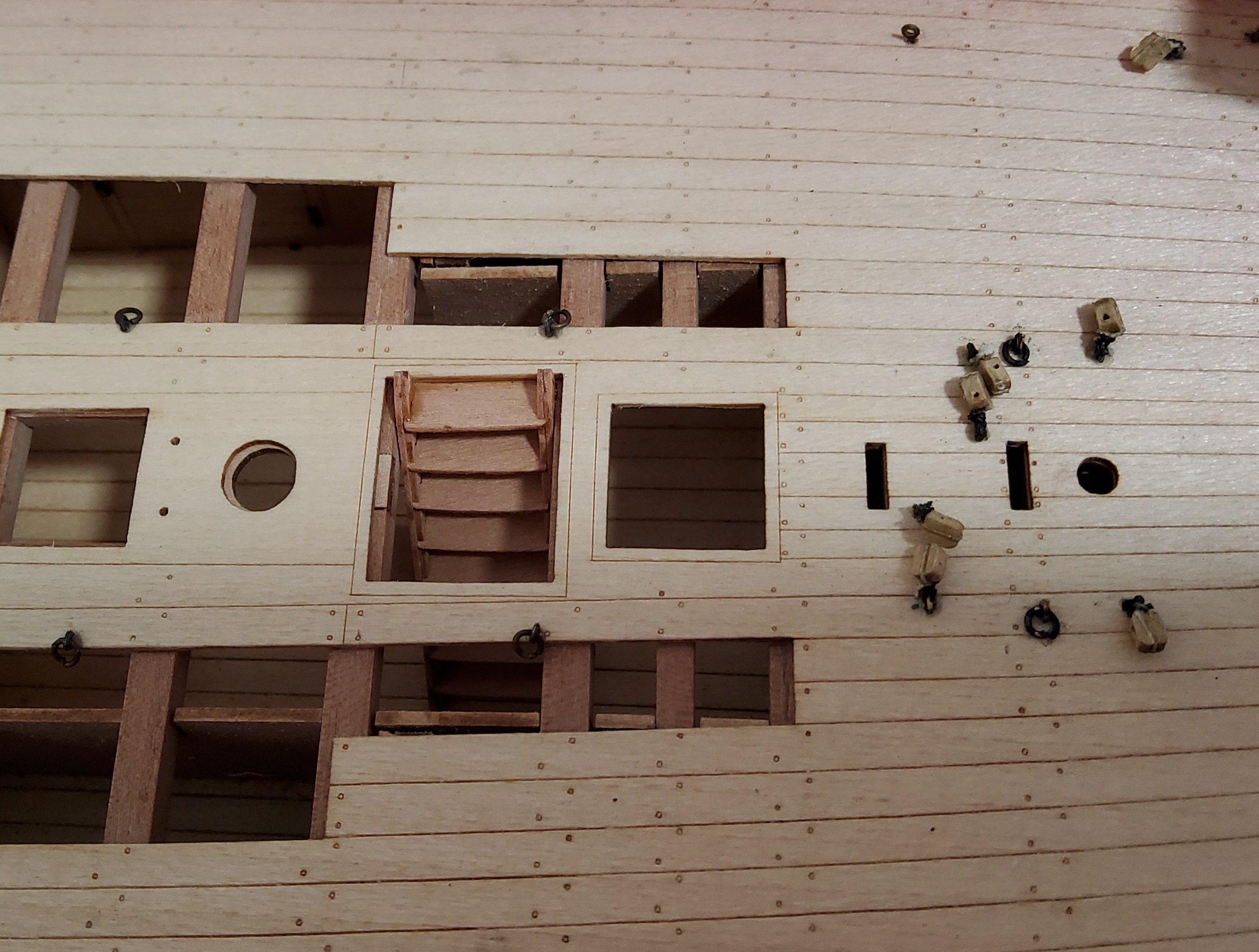
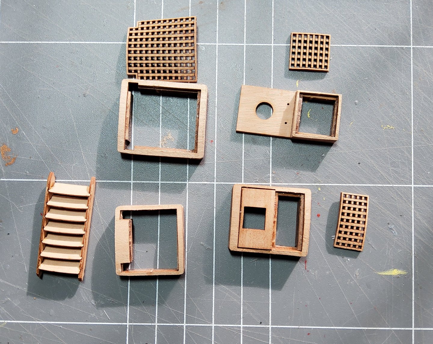
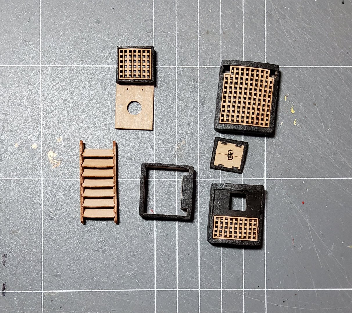
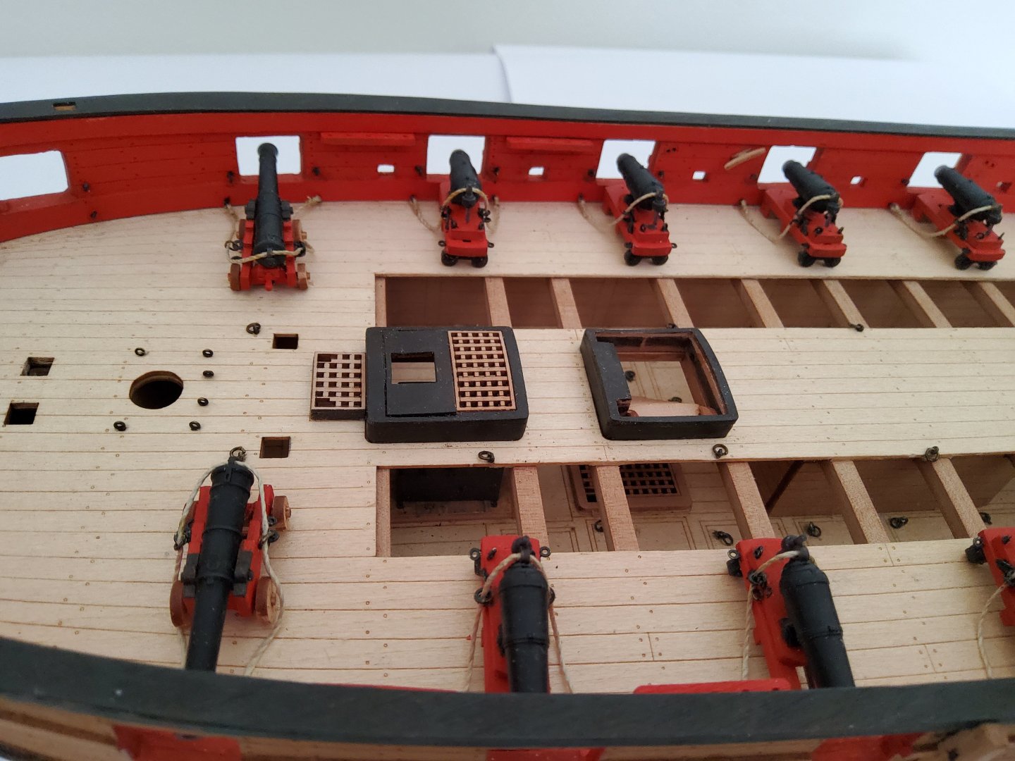
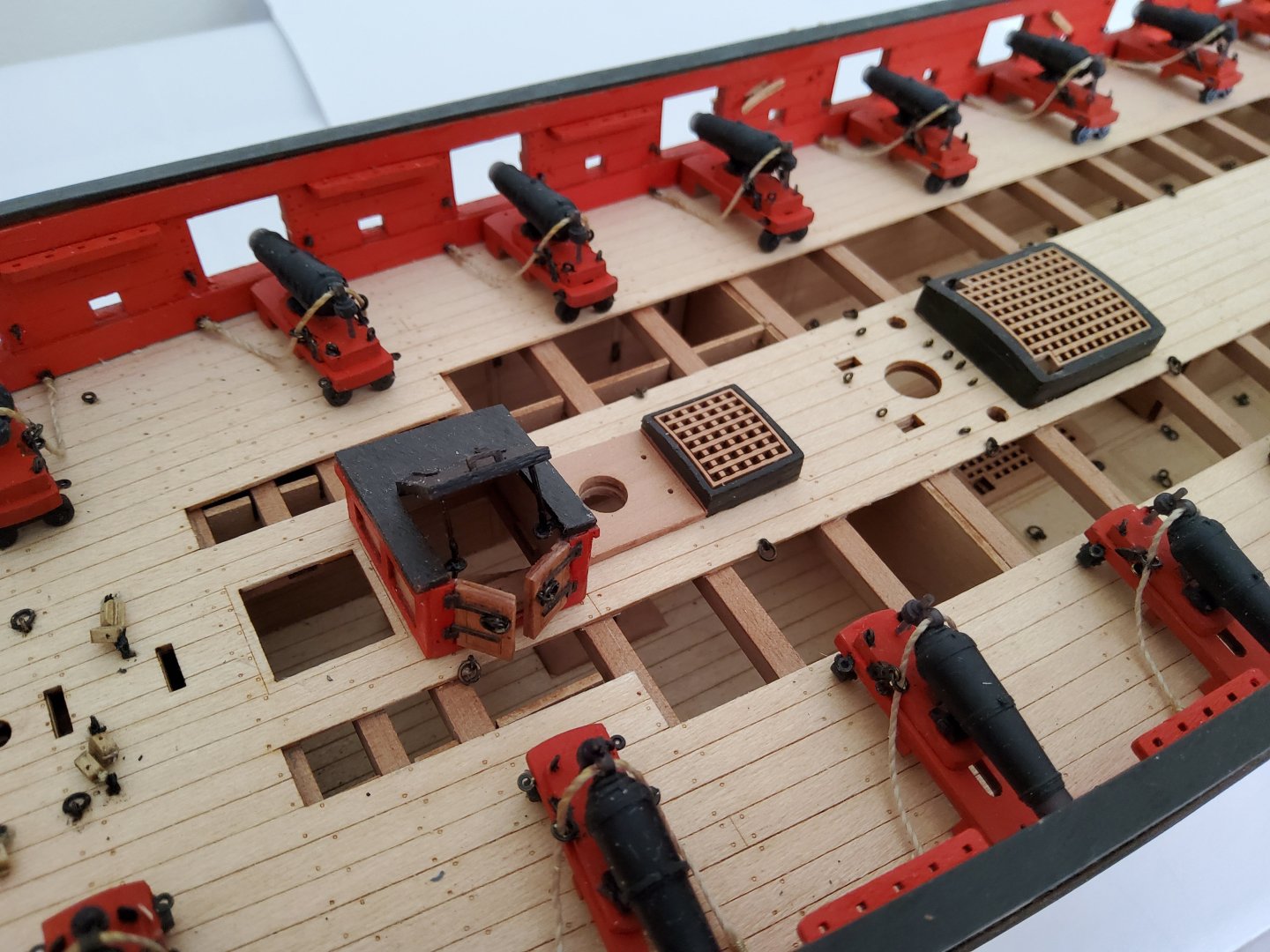
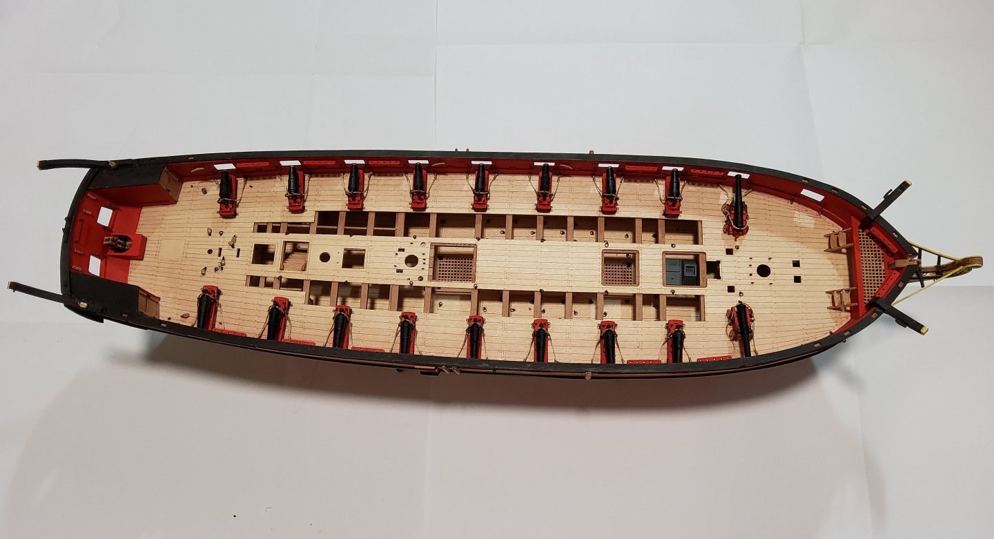
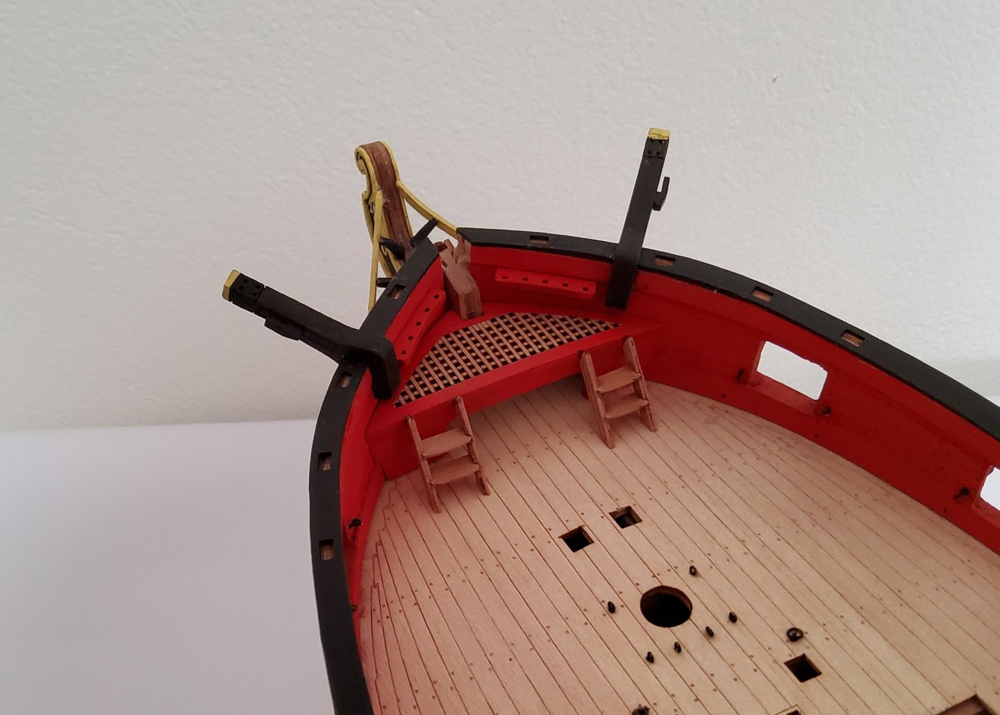
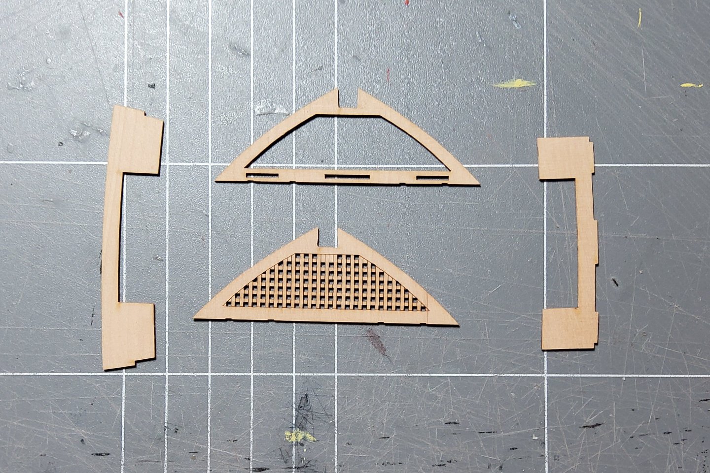
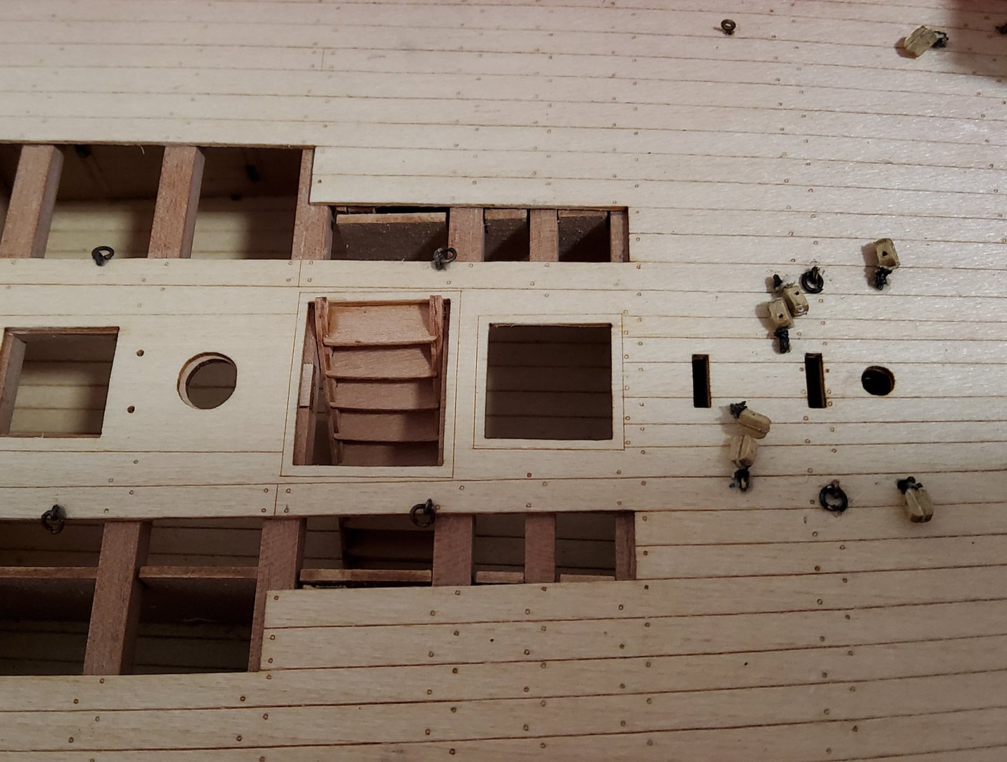
Thanks for all the likes, and to those who have just dropped by. The next job was to add the hatches along the centre of Harpy. The first photo is of the parts for all the hatches plus the completed ladder for the forehatch. The various parts were then painted and assembled. The actual gratings were firstly soaked for a while then bent around a suitably sized cup using masking tape to hold them in place, and left to thoroughly dry. Some of the gratings needed slight, gentle sanding to allow them to fit correctly into the coamings. No issues with that. When dry-fitting the completed hatches into their respective deck cutouts, some slight sanding was required to allow them to seat fully home (and this check should actually have been done before painting the coamings). Again no issue, but as always, dry-fitting before gluing was necessary to check the fitting. Lastly, the ladder for the forehatch was carefully glued in place. A little tricky, but yet again, a couple of dry runs before gluing, sorted out potential problems. The previously completed companionway was also added at this time. Cheers.

-
Thanks Maurice.
-
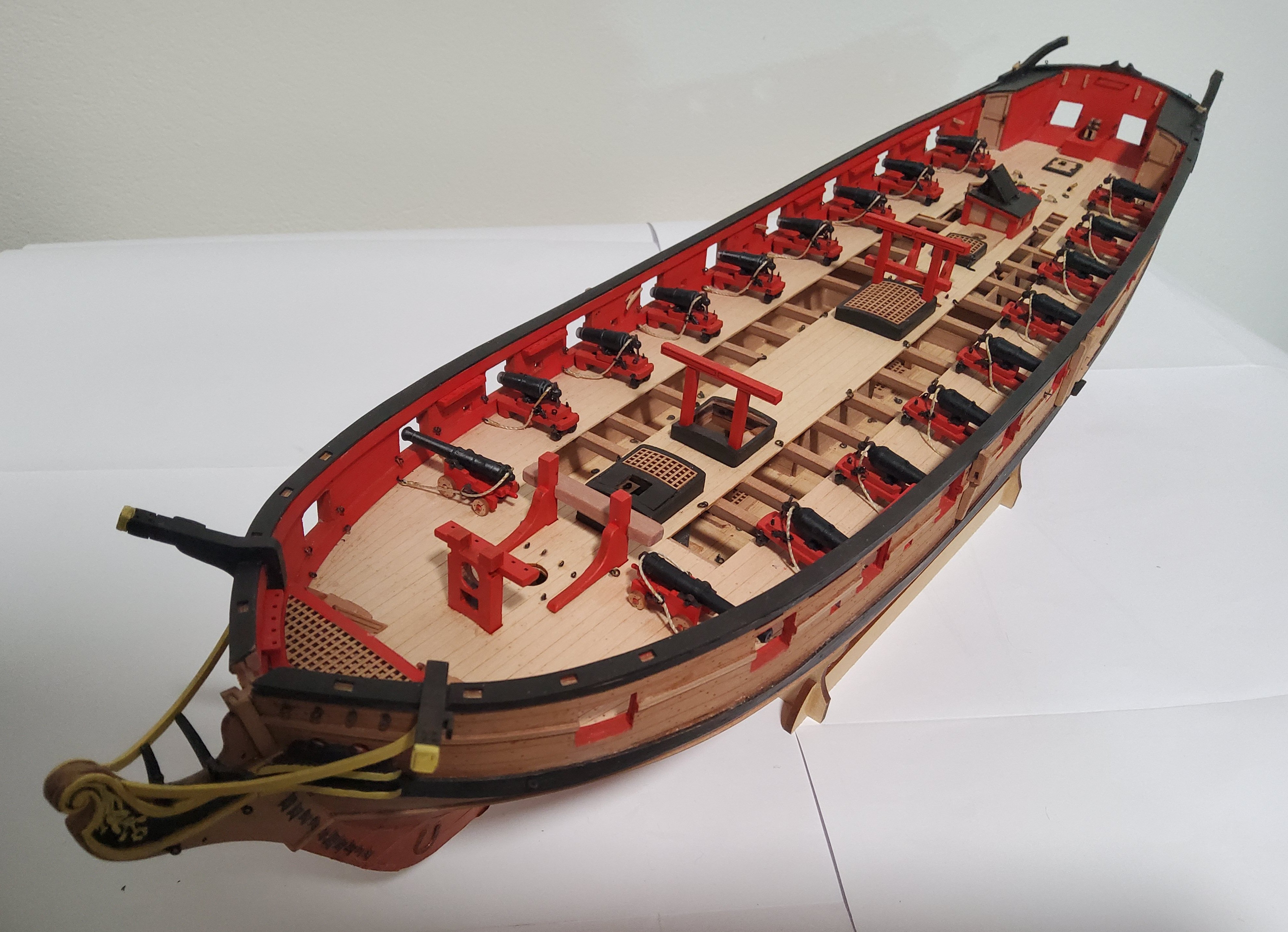
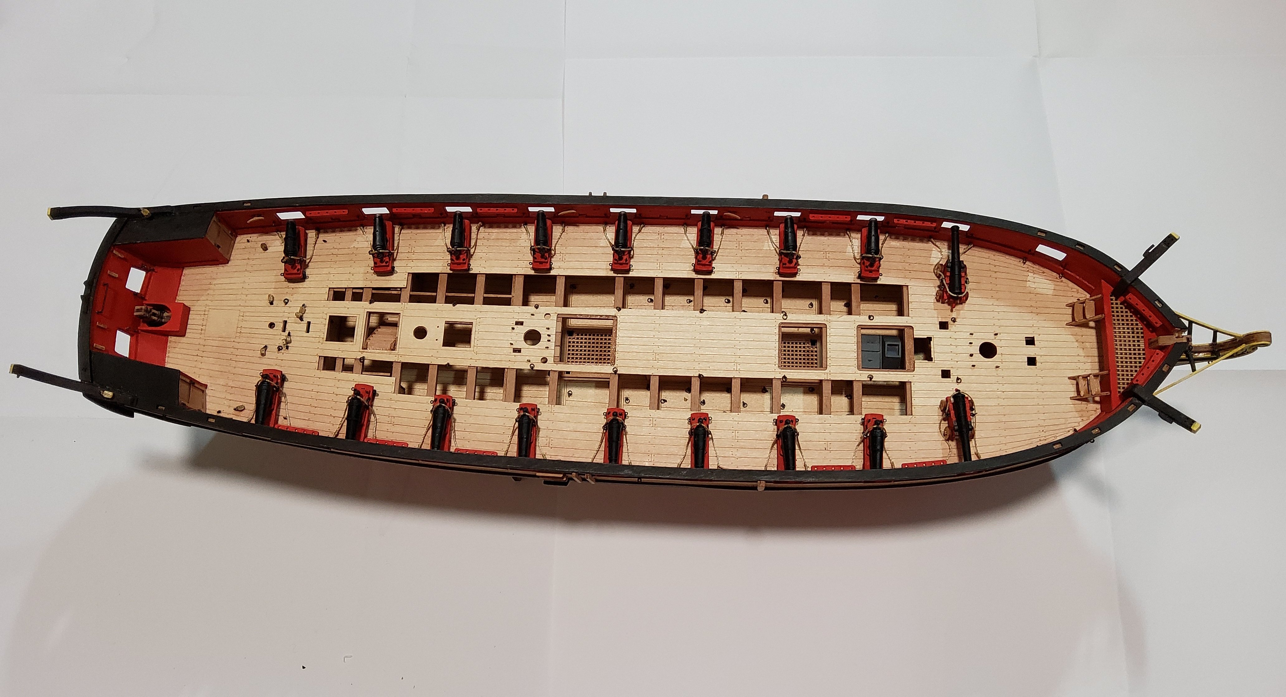
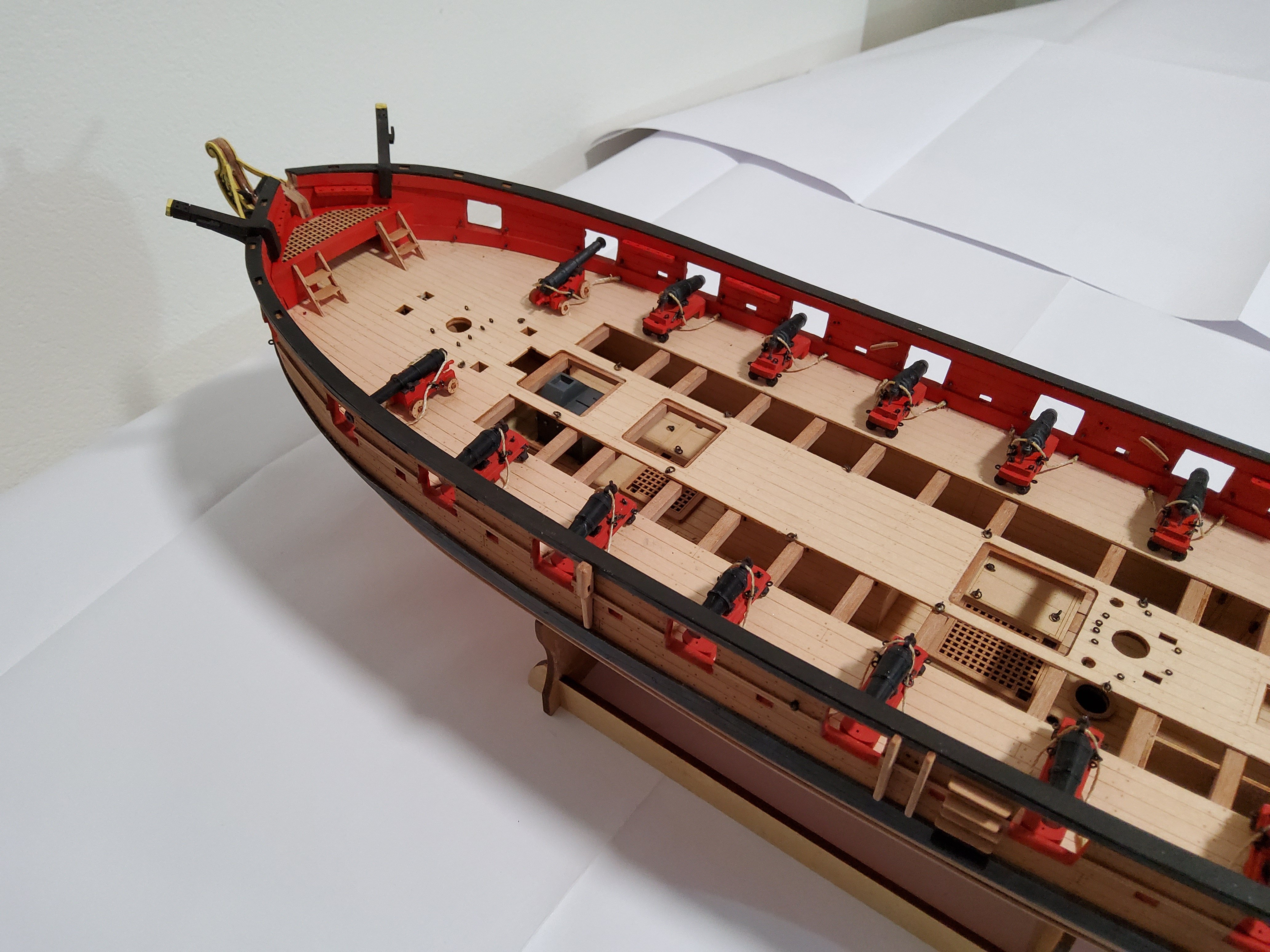
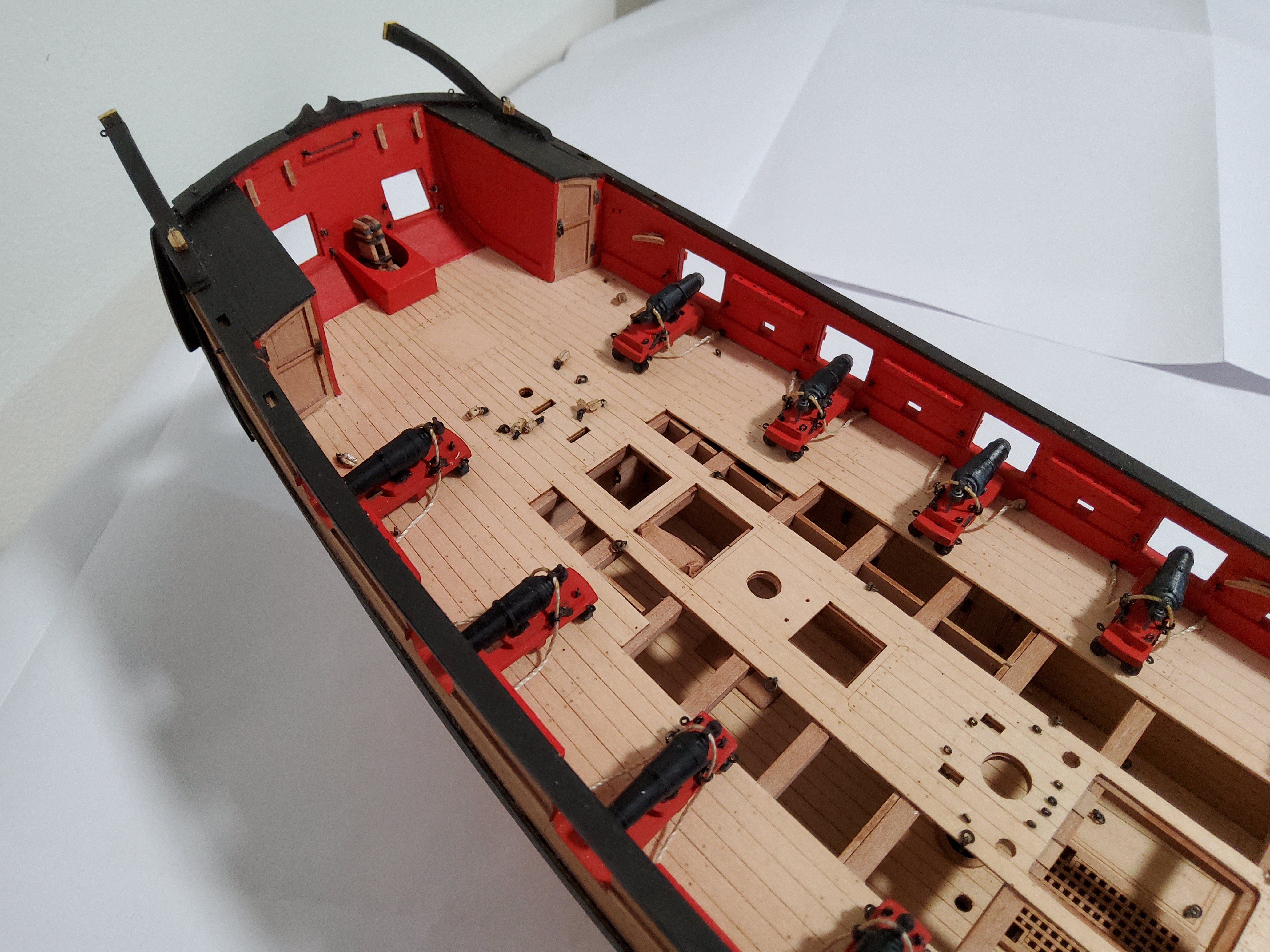
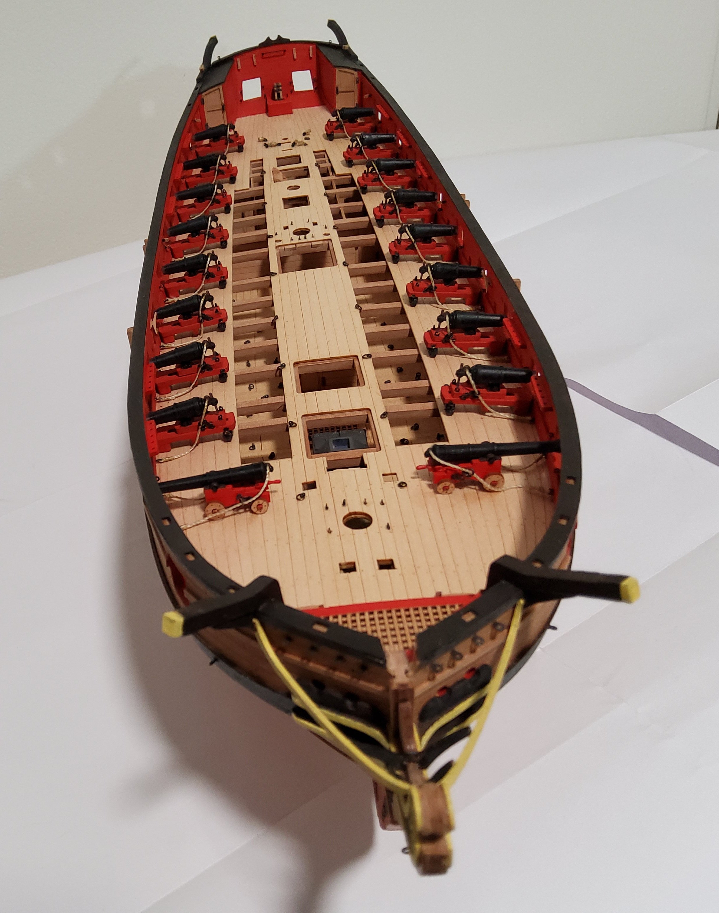
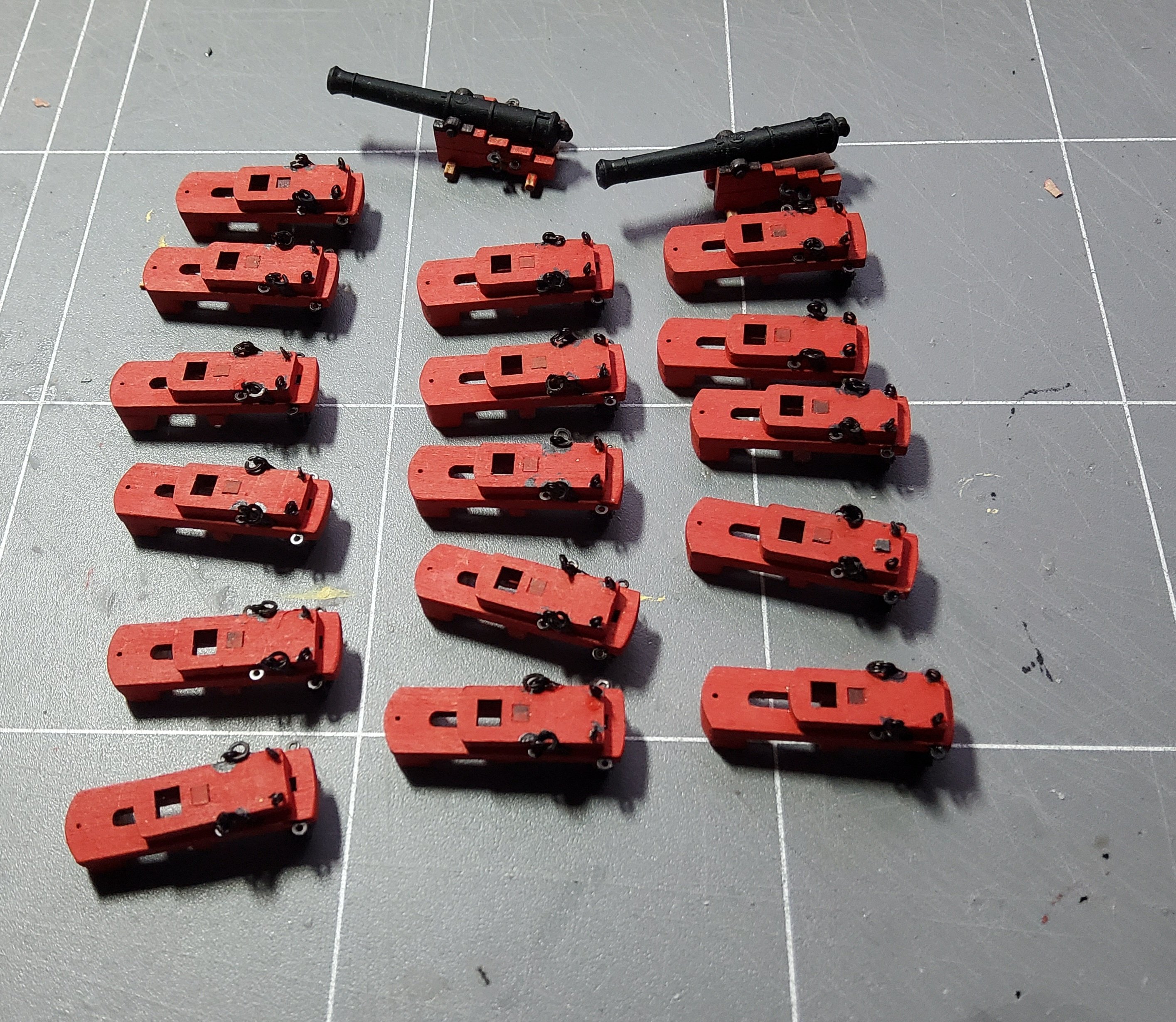
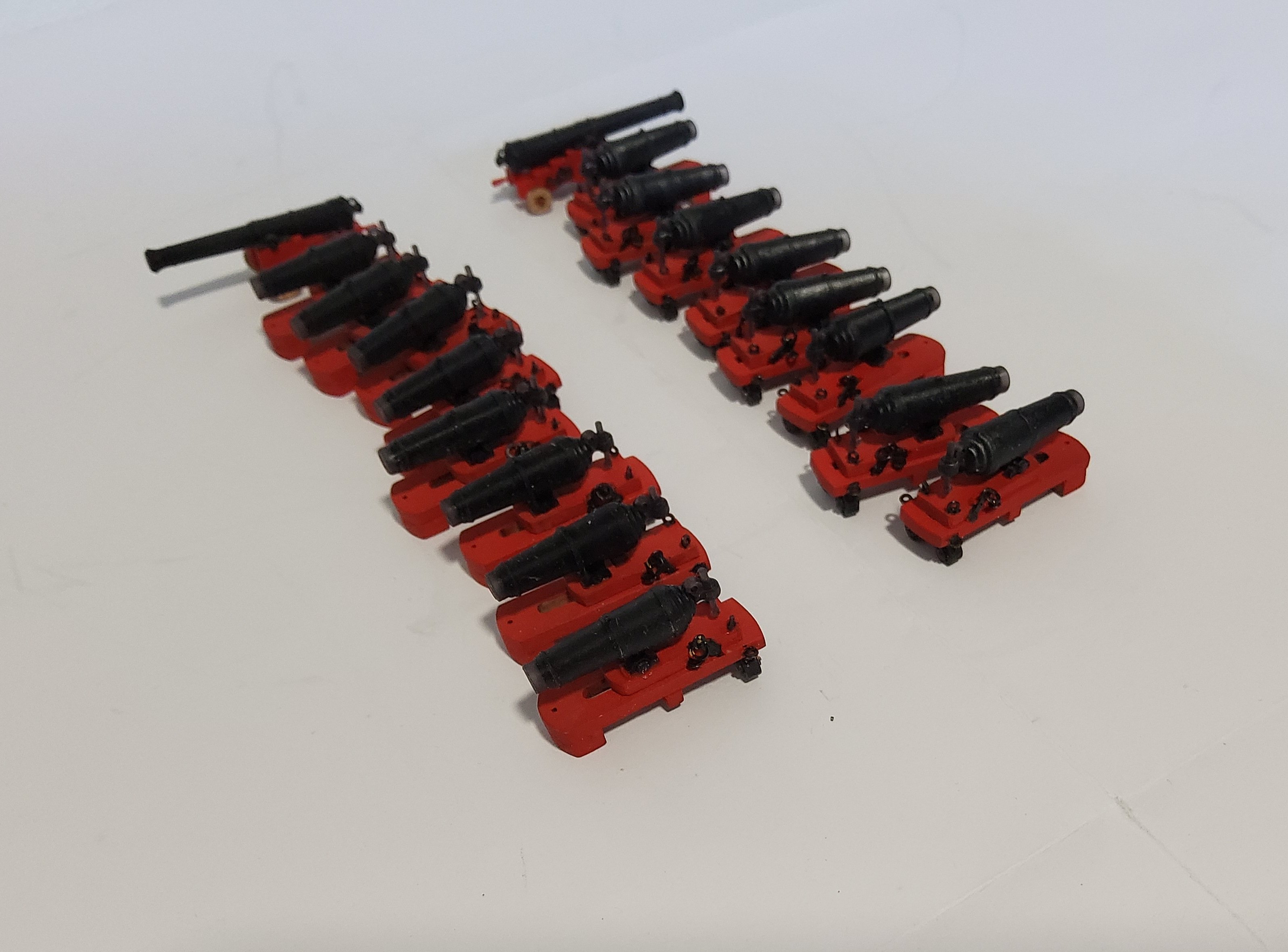
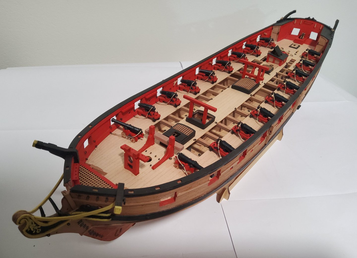
Progress has been slow due to lack of spare time. Nevertheless there has been some. The guns are finished and in place on the ship. Only the breeching ropes were rigged and this was done off-ship. Cheers


-
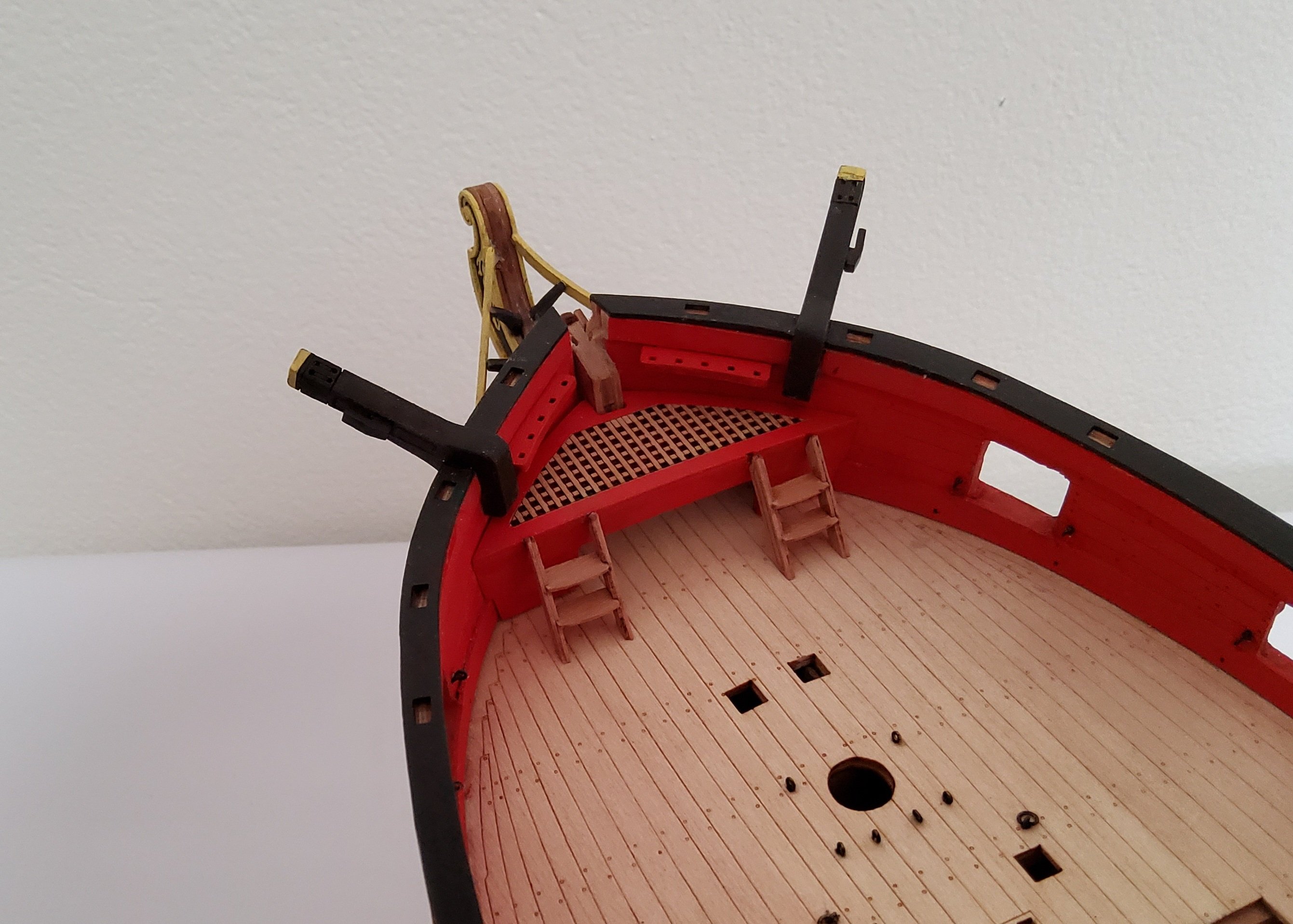
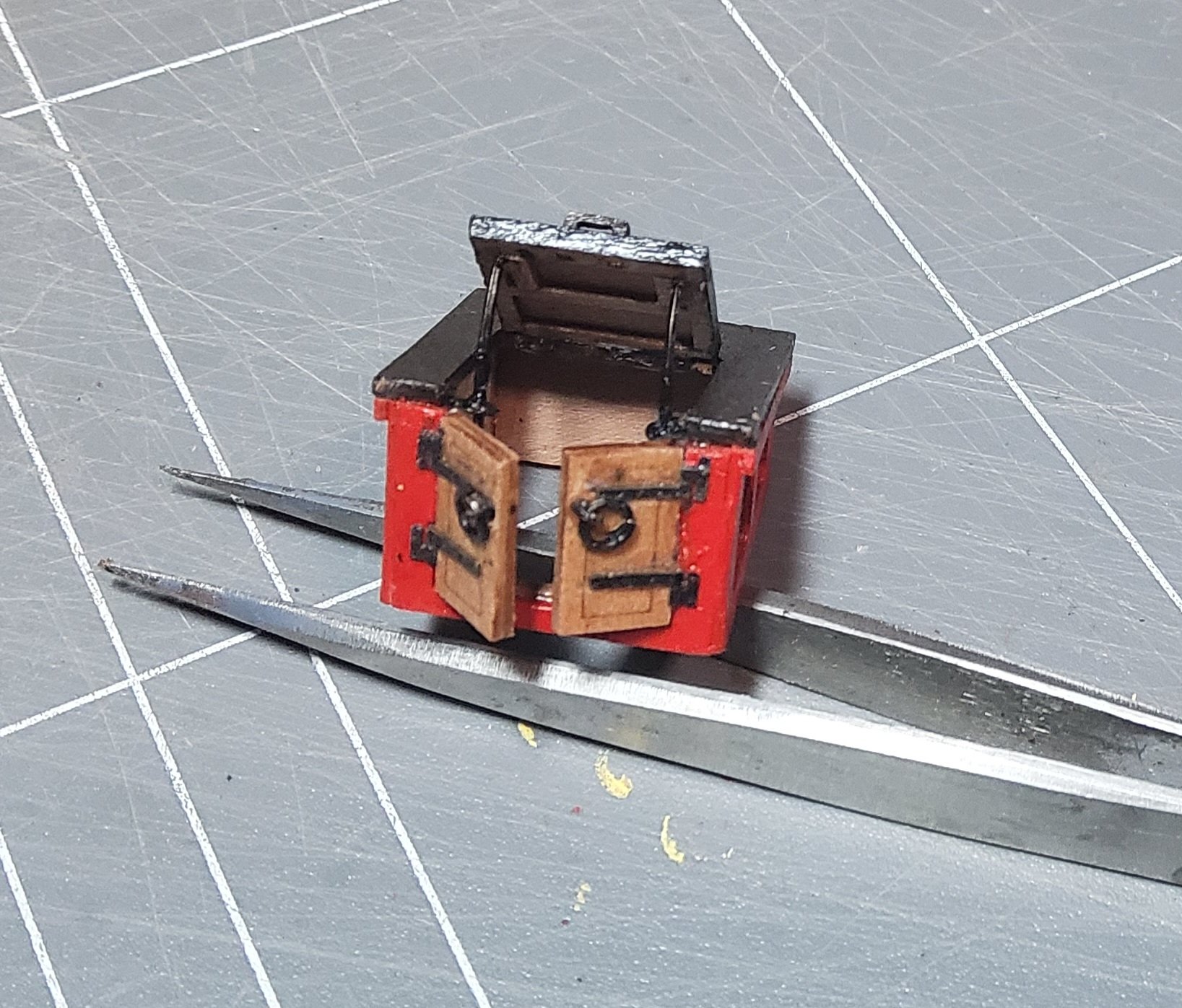
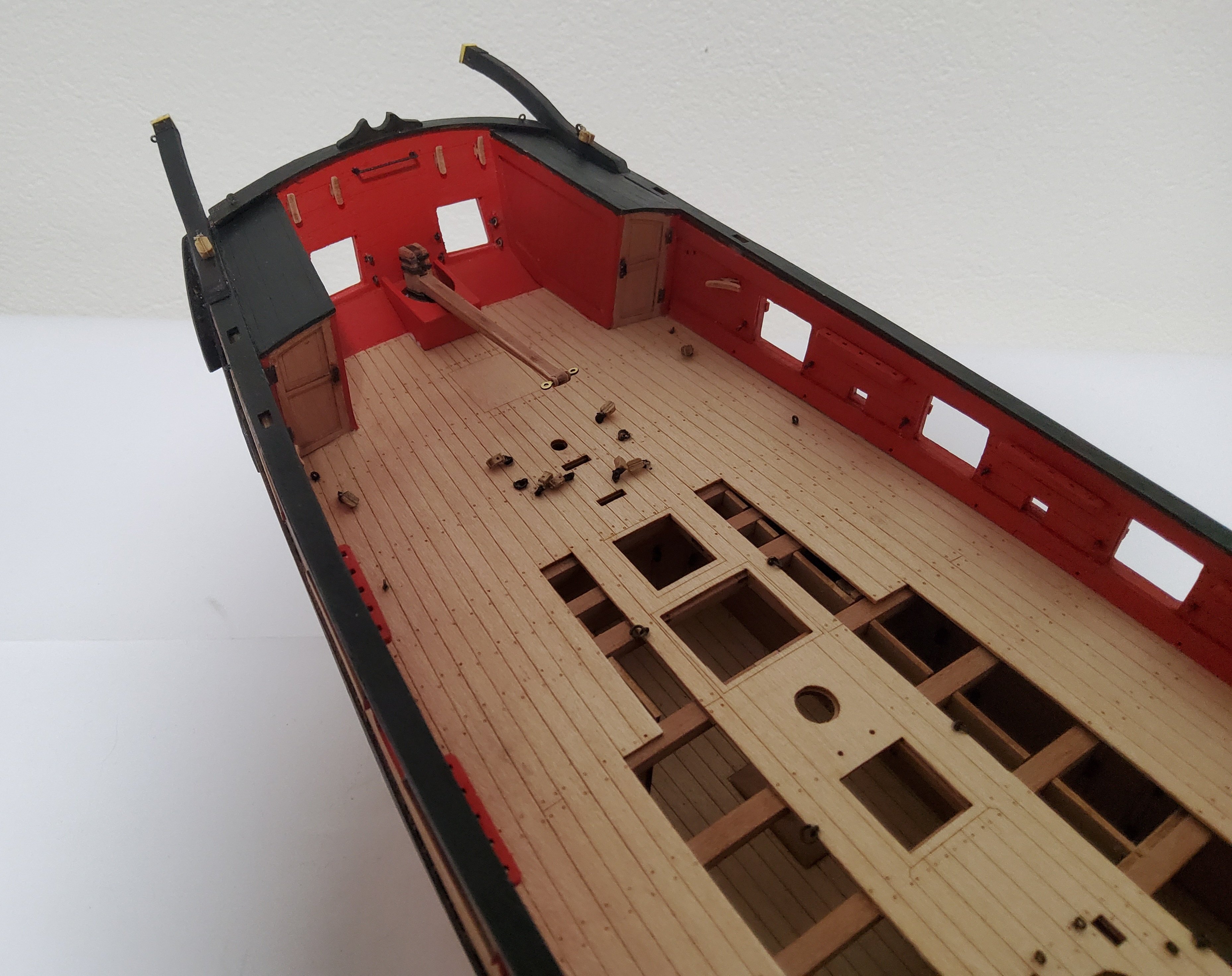
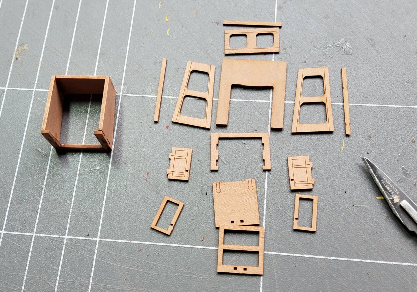
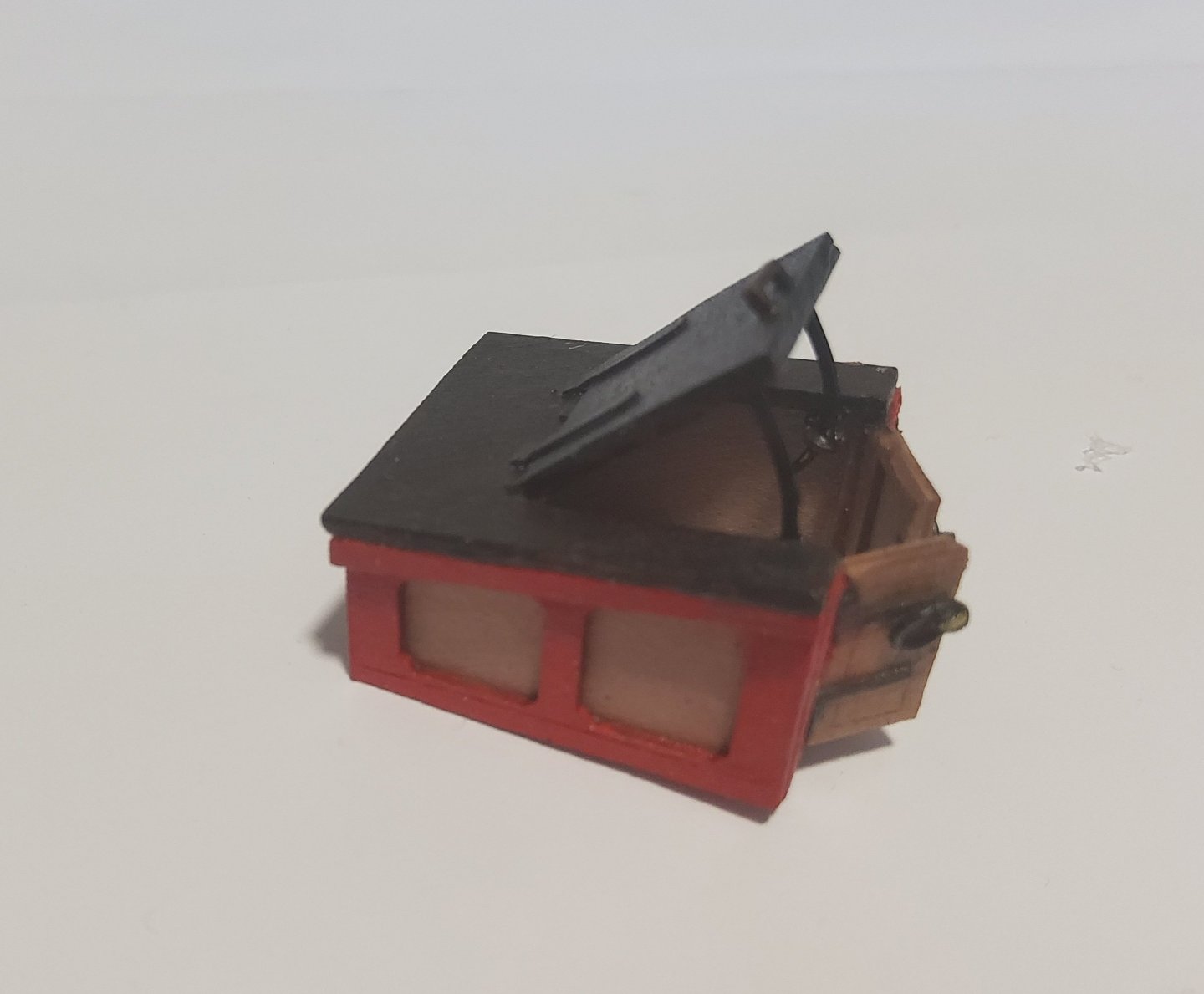
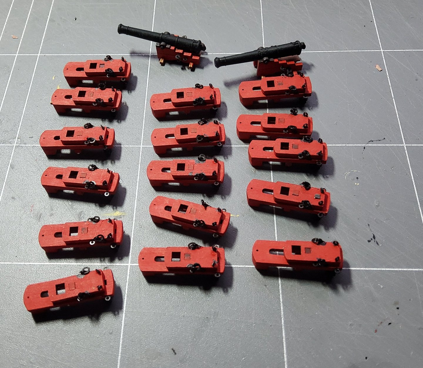
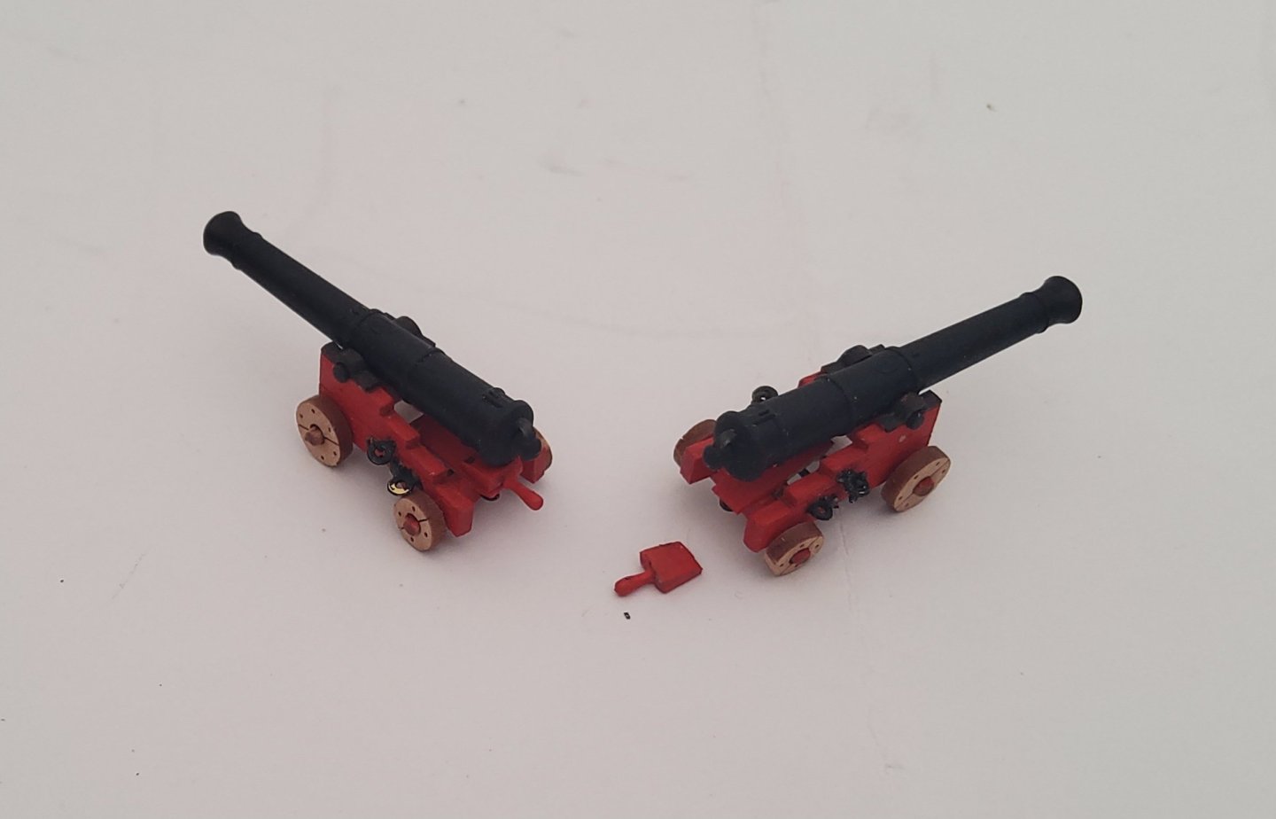
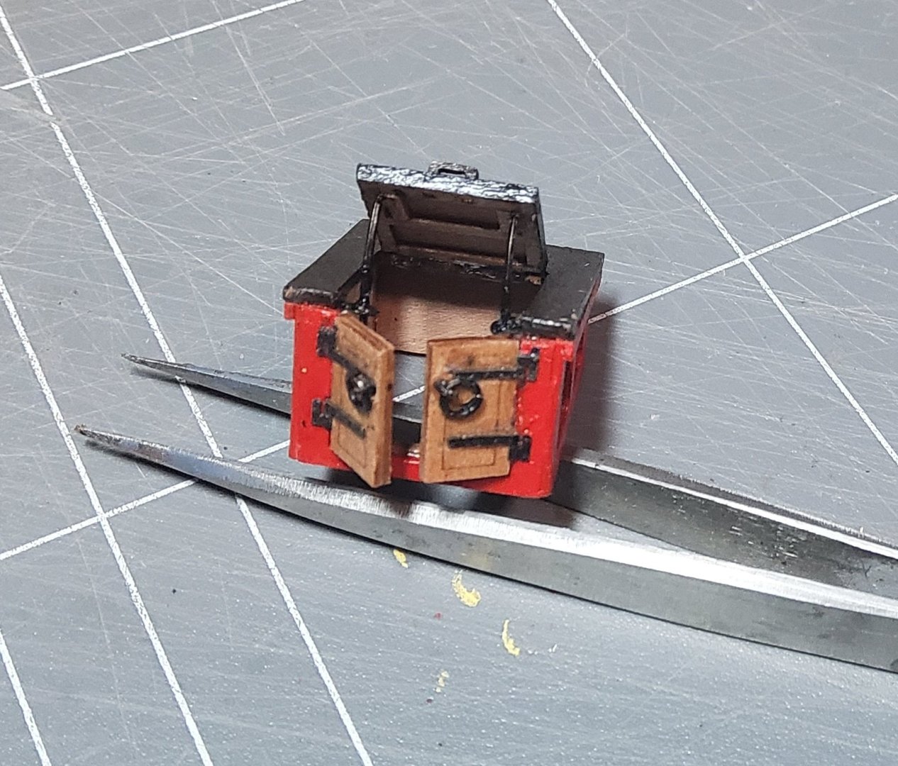
Thanks for all the likes and comments, and to those who have just stopped by. Some more progress. The first thing to do was assemble the fore platform, only four parts. It was glued together, then dryfitted, gently sanded, dryfitted etc until it was a good fit into the bow. When I was satisfied it was glued in place. The two short steps to the platform were added at this point. A longer set of steps were assembled and glued in place. The companion way fits above these, and making this proved to be a little tricky in places. The parts for it are shown below, with some pieces already glued together. The more interesting facets of this build were the two doors at the front and the hatch on top. The instructions say that these can be left closed or open. I chose to have them open. The doors were no particular problem, except for adding the hinges, provided as PE. I glued the doors in the open position then added the hinges (the handles, ring bolts, had been fixed already), but ran into some problems with the PE hinges in trying to get them to fit correctly. I finally used some of the Syren hinges I'd used previously. The hatch however needed a little more attention. As Blue Ensign said in his log, the hatch needs support in the open position. For the two supports I used some leftover PE, bent into a curve, glued to the underside of the hatch with the lower ends held in place by small eyebolts fastened to the sides of the companion way. Syren hinges were again used. The guns were assembled over several days, usually while waiting for glue or paint to dry. Assembly line. Patience is required. I didn't add Part 227, described as the "quoin" in the instructions for the long guns. Instead I replaced it with a short piece of 0.6mm fret to represent the bed of the carriage and added two separately made quoins. (The left carriage needs a paint touch up.) Finally, a word of thanks to Blue Ensign (Maurice), who continues to suggest improvements that can be made to an already superb kit (thanks Chris), some of which are obvious in my build. Cheers.

-
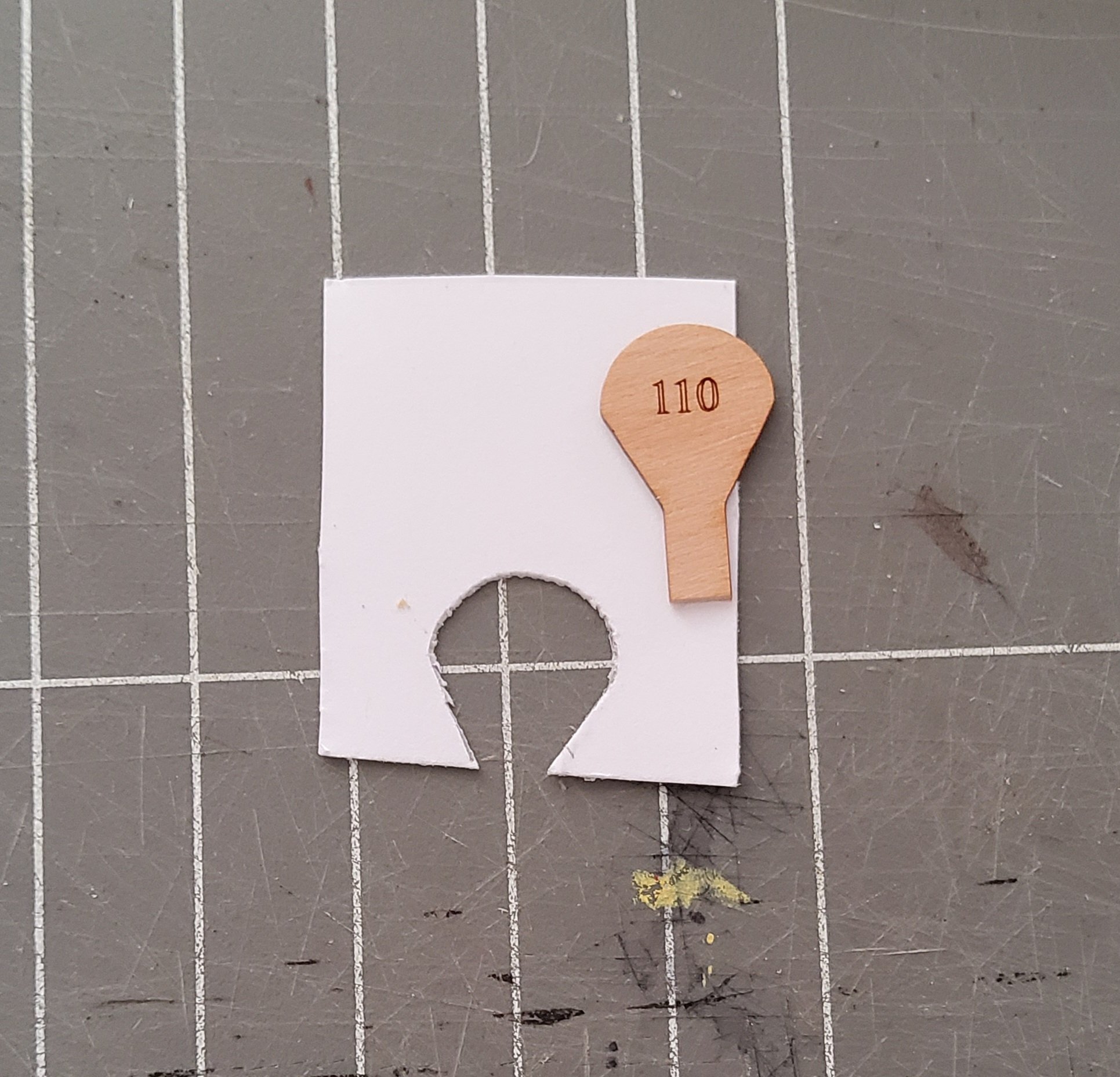
Thanks David. I had one go at trial-and-error cutting of the card, but then it dawned on me that I could use the fret as a template. Easy as.
-
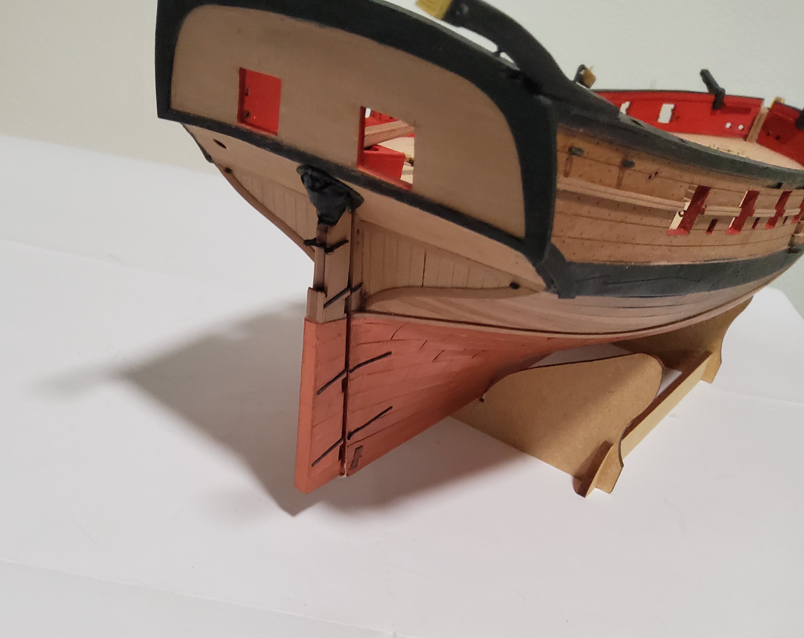
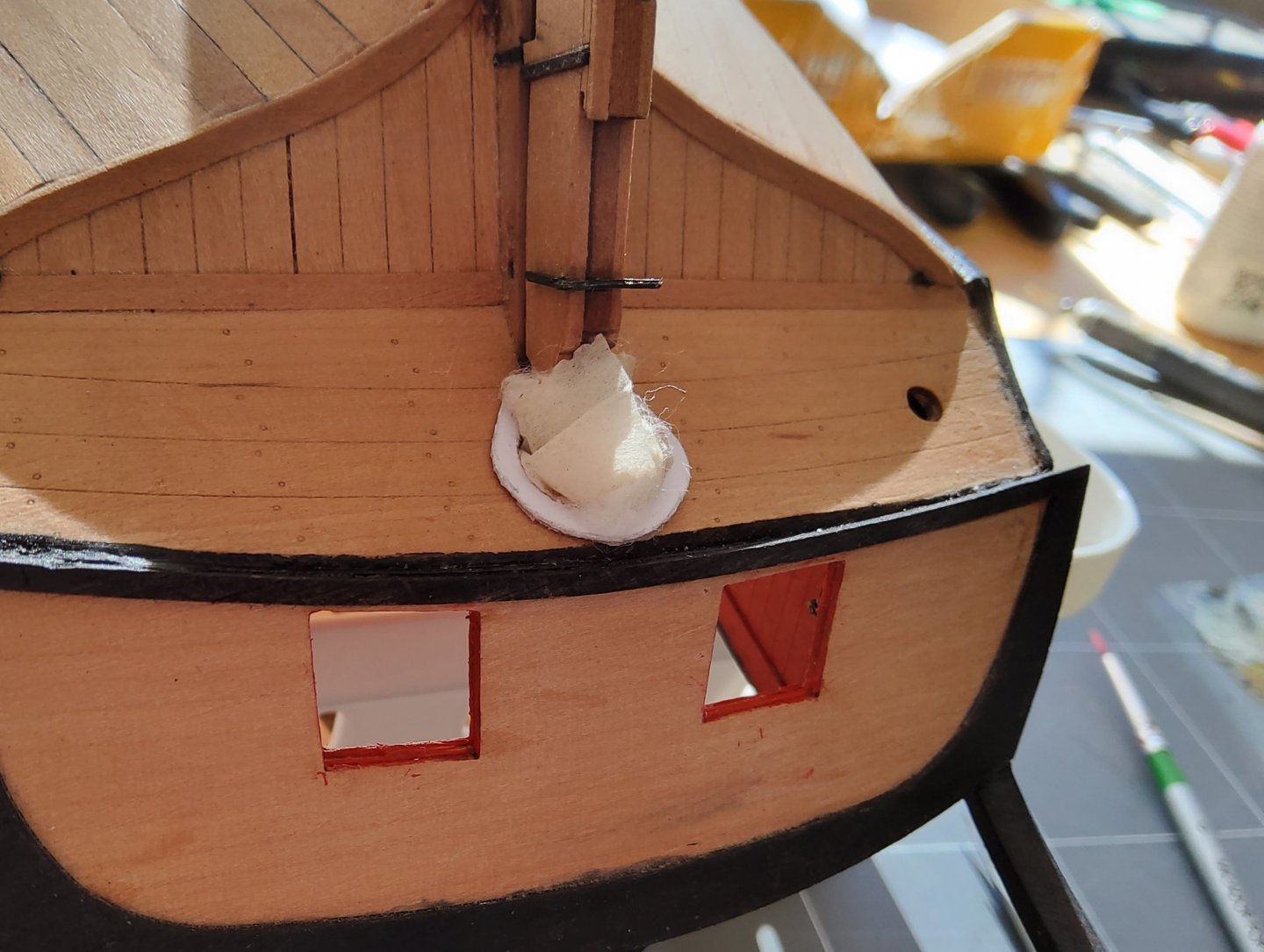
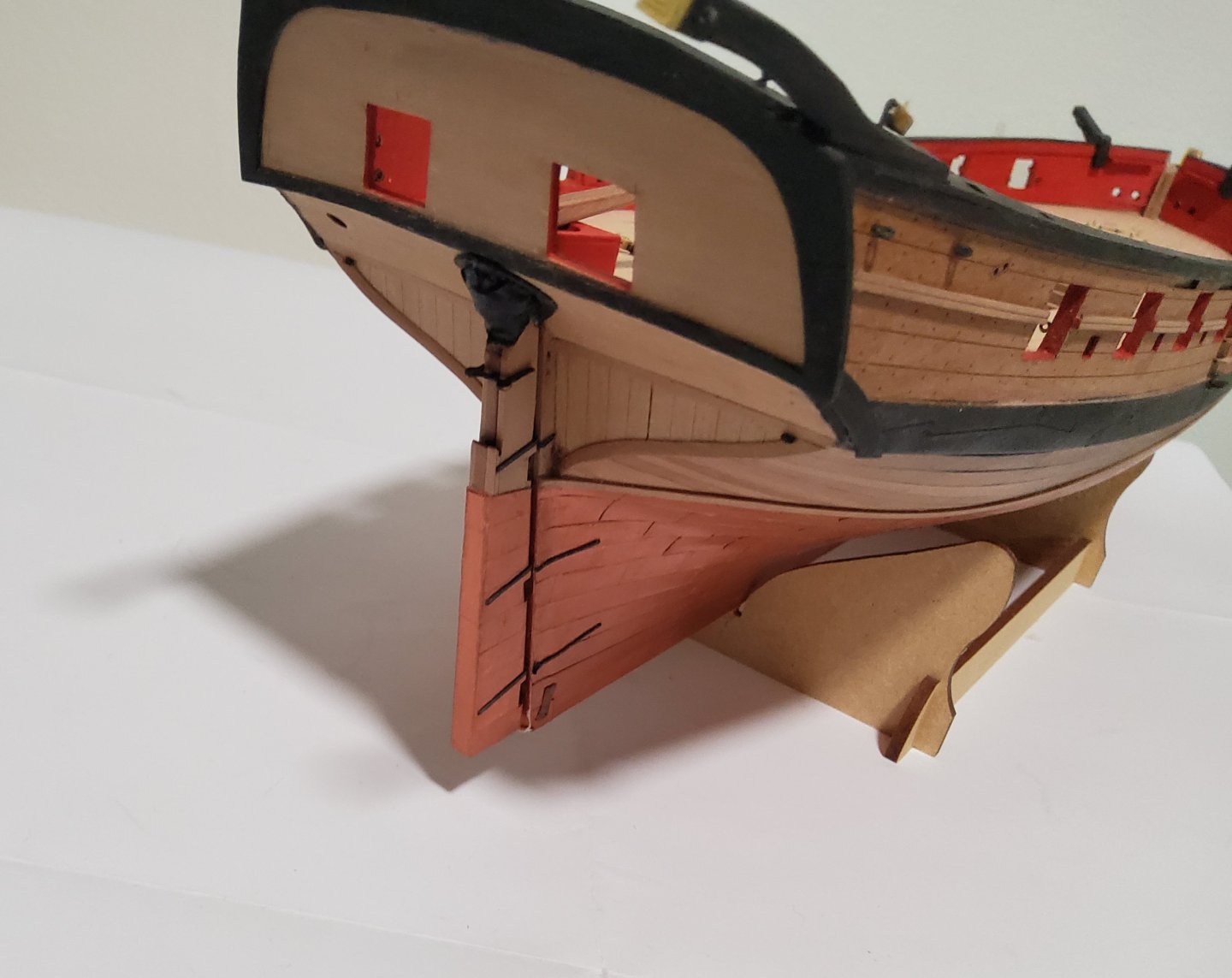
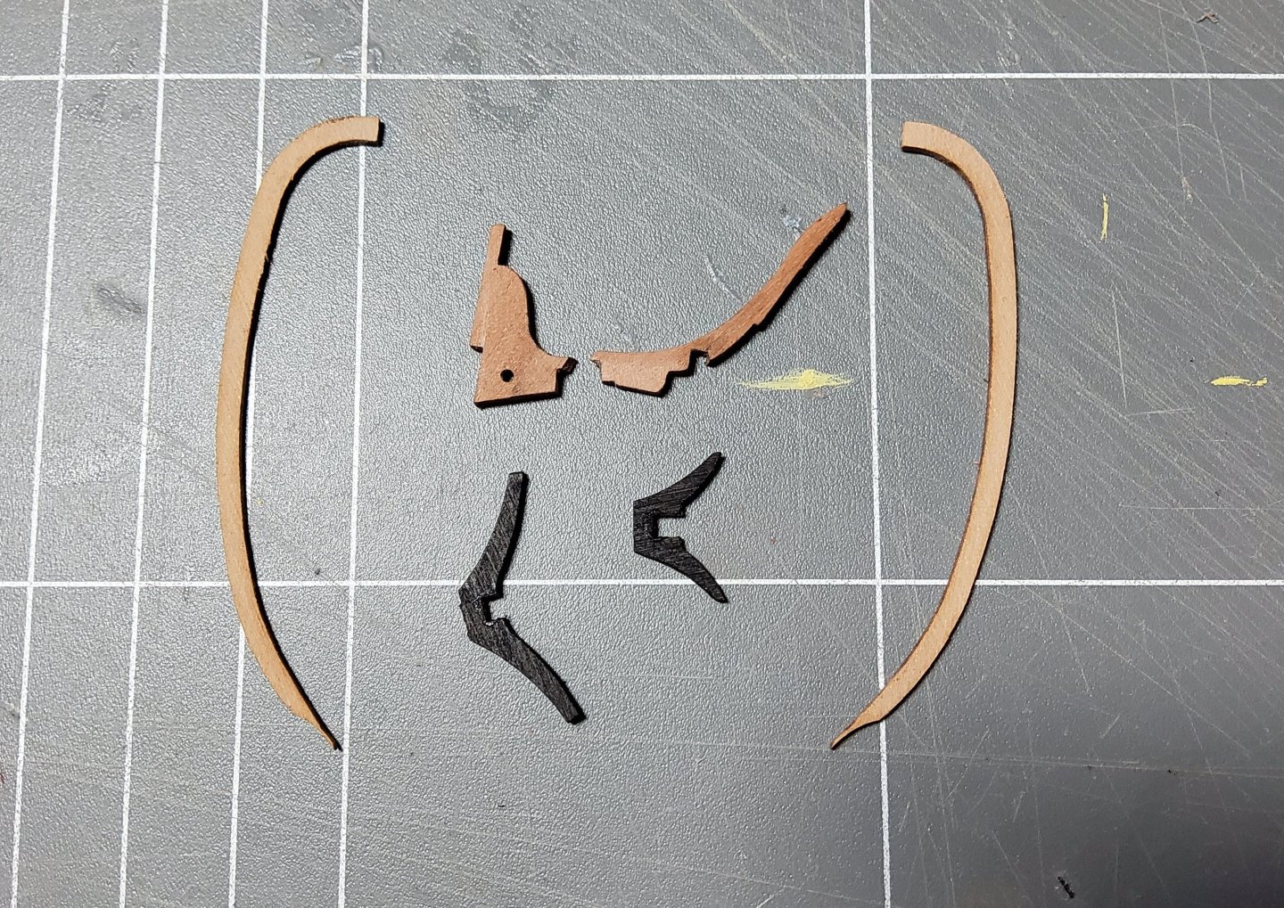
More progress, but not a lot to see. The eyepins/ringbolts were all added, with blocks seized to them where required, mostly those associated with the steering tackle. The instructions call for these latter blocks to be 3mm in size, but to me, these looked overscale and 2mm blocks were substituted. The ringbolts were made by adding a brass ring to the PE eyepins. All pin racks and cleats were glued in place. The tiller is in place but not glued. The rudder has been sitting out of harm's way, but was now fixed to the hull. Following Blue Ensign's example, a rudder coat was fashioned to fit around the rudder where it passed through the lower counter. I made one of these for my Pegasus build but couldn't remember how I'd done it so I referred to B.E's detailed description of his method in his Alert build log (here) and I more-or-less followed his method. Briefly, the coat consists of a canvas "bag" held against the rudder and the hull by a metal plate. I made the "metal" plate first, getting the inside shape by using a piece of the fret that had contained the lower counter, and then simply eyeballing the outer edge to give me a horseshoe shaped plate. Card was used. I had no fine material for the bag so used surgical tape instead. The plate and the tape were glued to the hull, leaving the tape baggy enough to stuff some cotton wool into it and then moulded it to suggest a bag. Once satisfied with this, I painted the coat with a mix of black water-based acrylic and PVA. Card and the piece of fret used to get the inner shape of the plate. The partly stuffed bag. Cheers


-
OK, time to 'fess up. I made a serious mistake that can't be corrected 🤒😬. If it had been two pieces of wood I could have de-glued them, but once two pieces of card are glued together, that's the way they will stay. I had however, photocopied the sheets from the kit when it arrived, and I have some 1mm material i can use for laminating, so all is not lost. There will however be a brief interval till I catch up with myself 🥴. Cheers
-
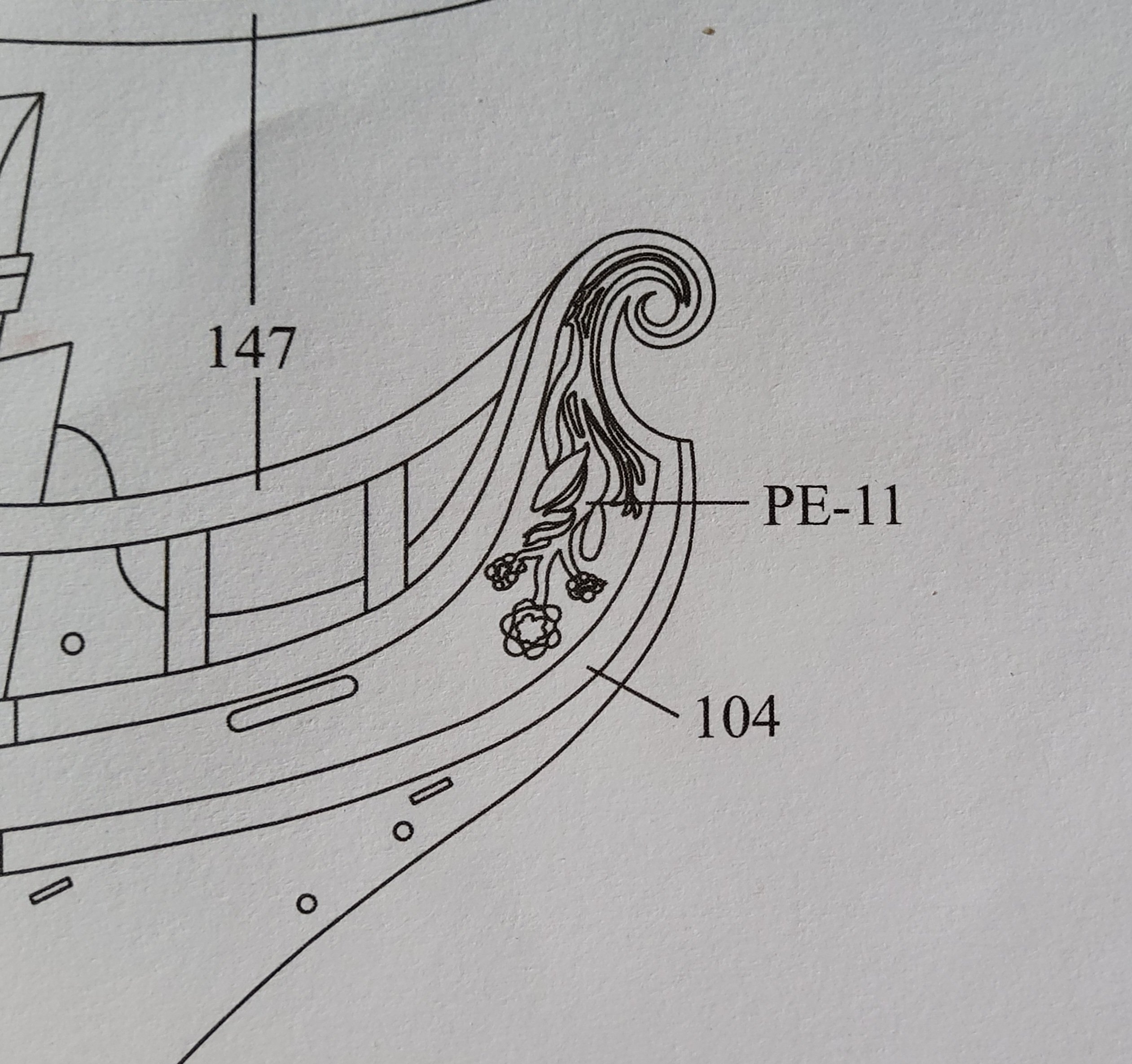
Thank you for the kind comment François. Yes it is a flower. Cheers

-
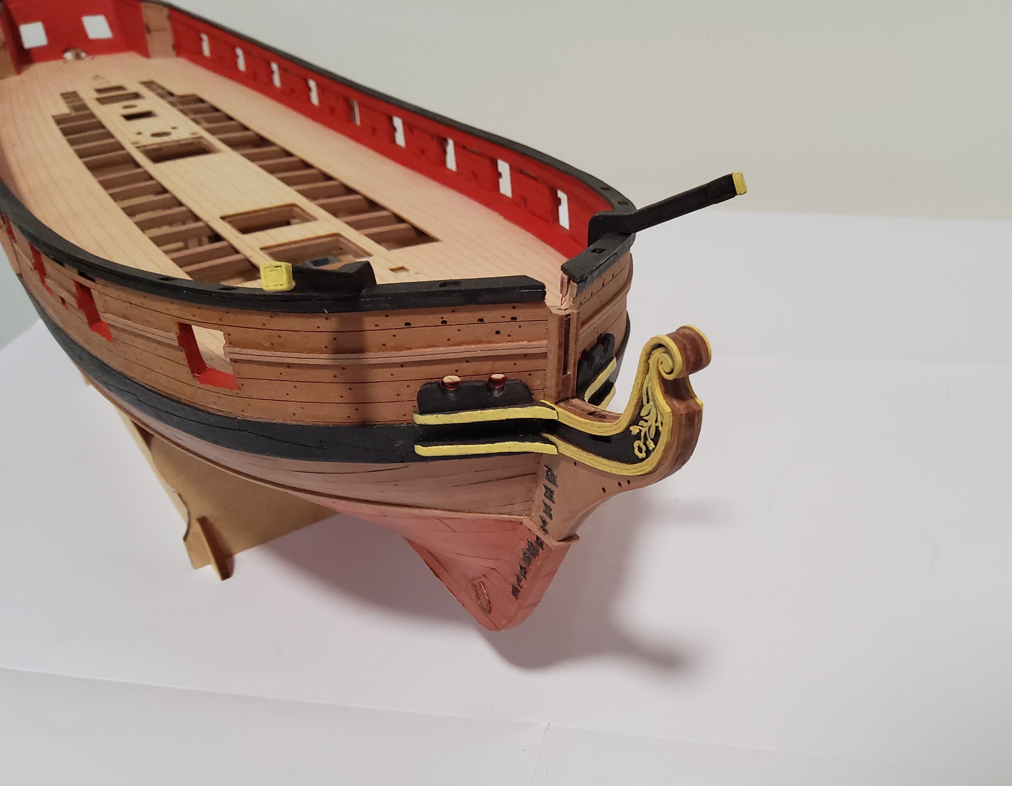
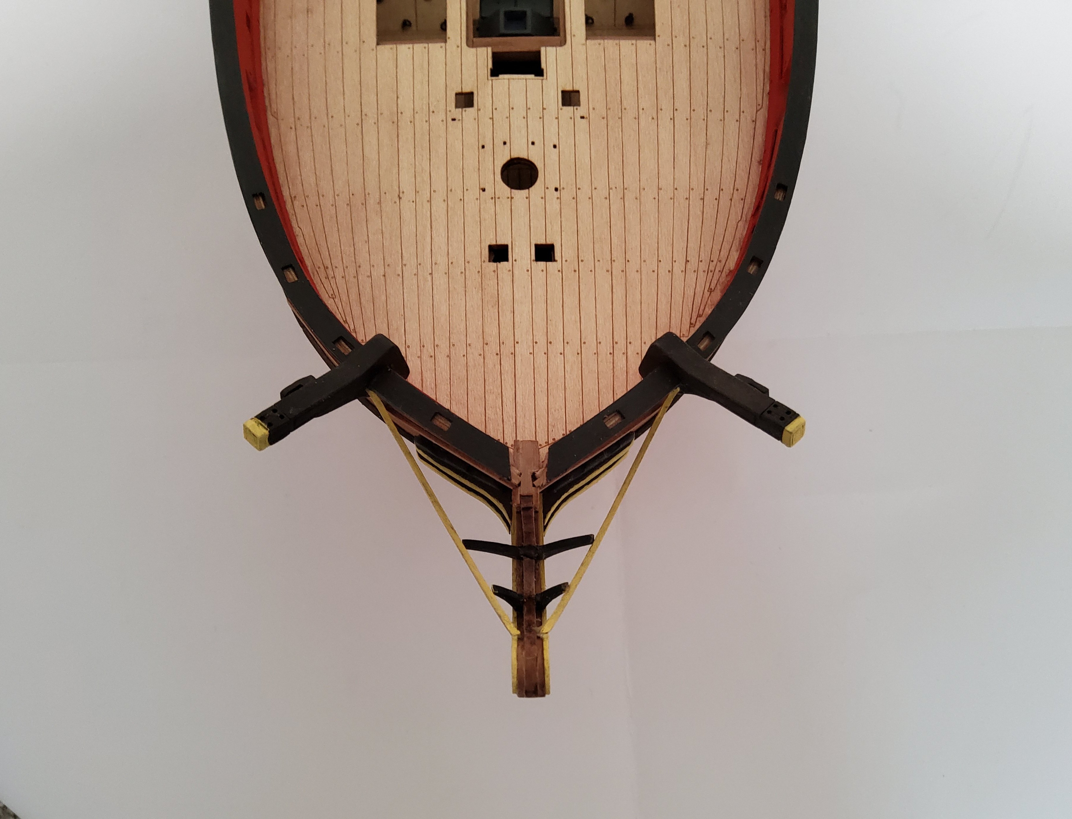
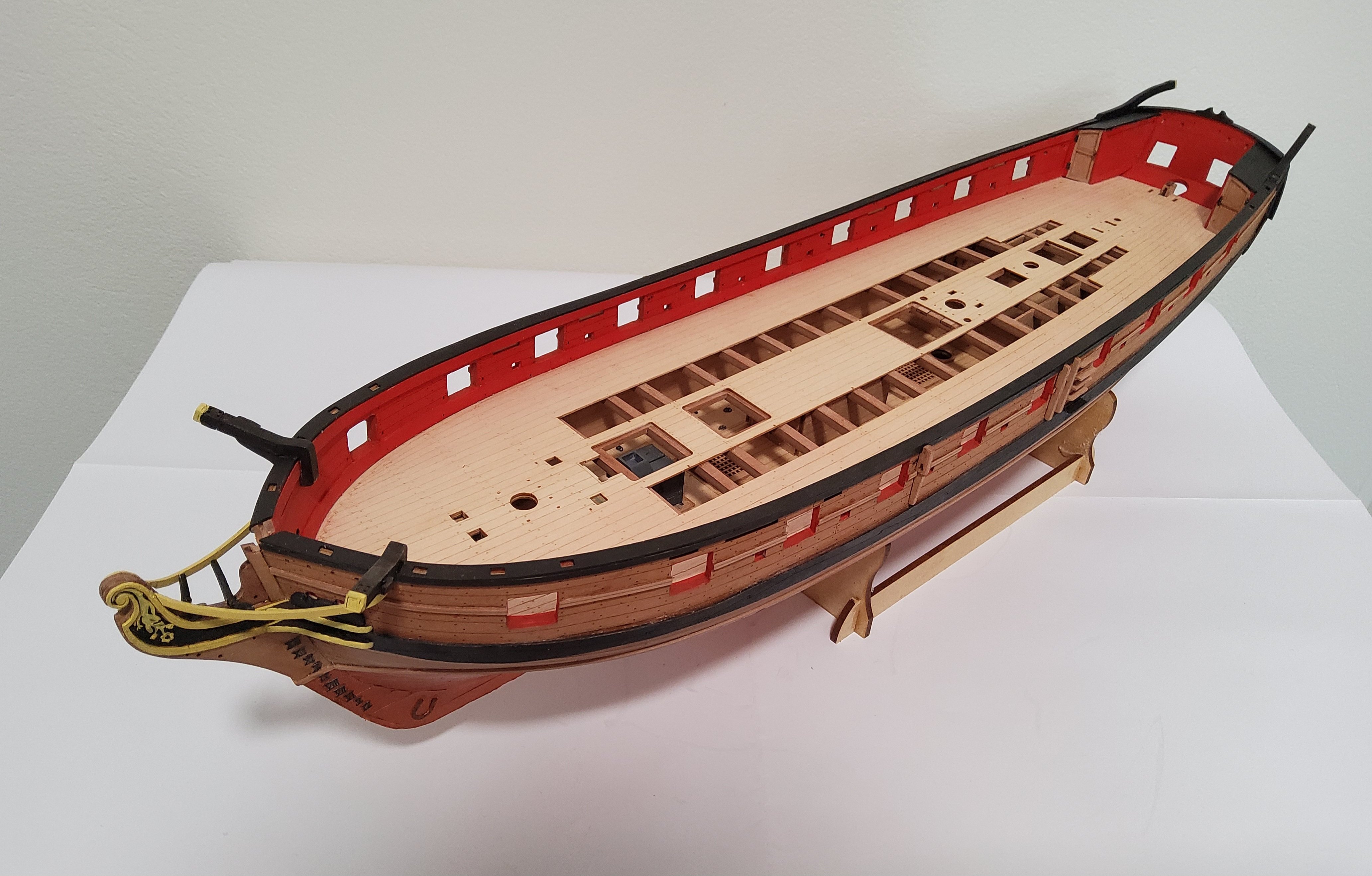
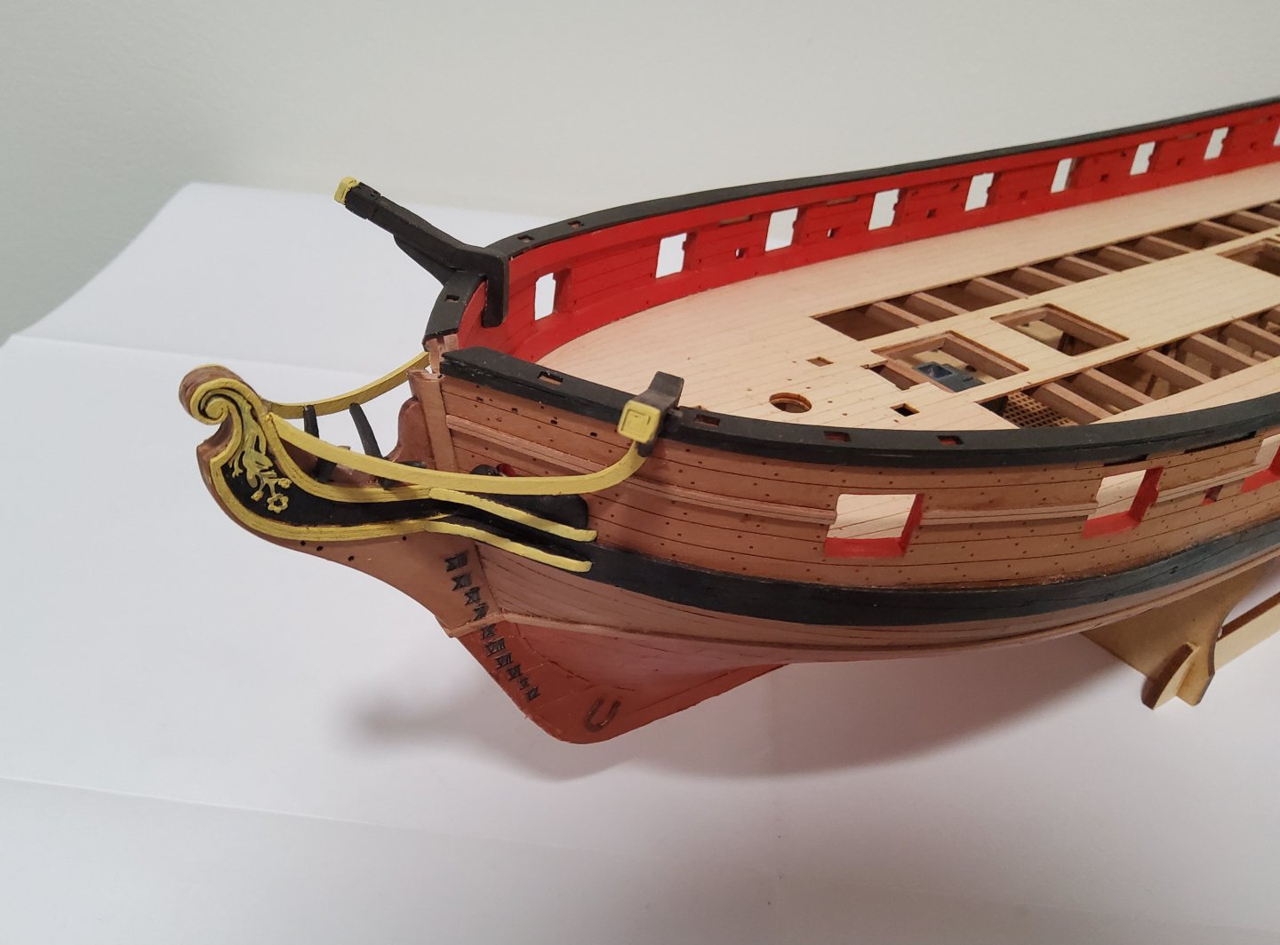
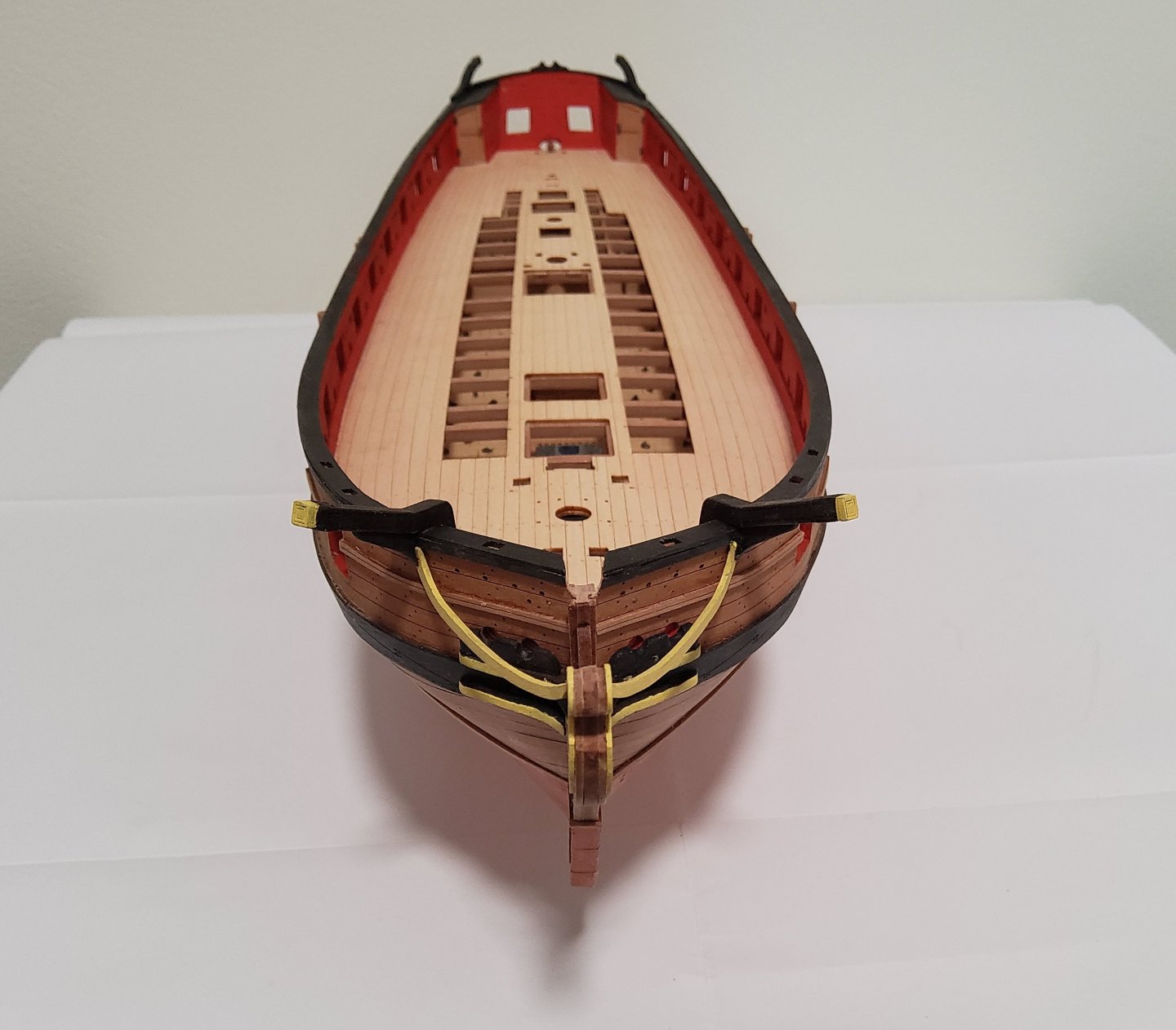
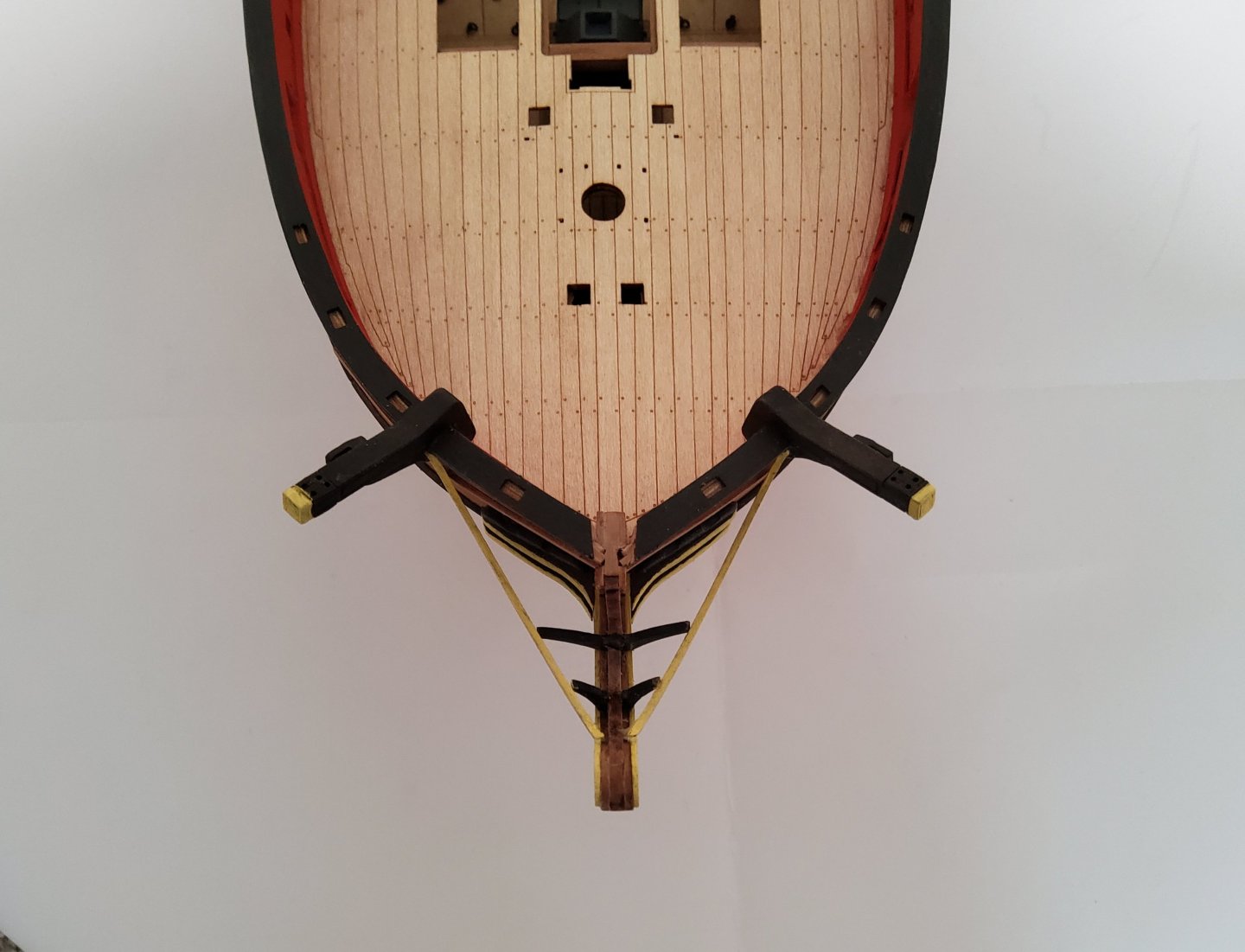
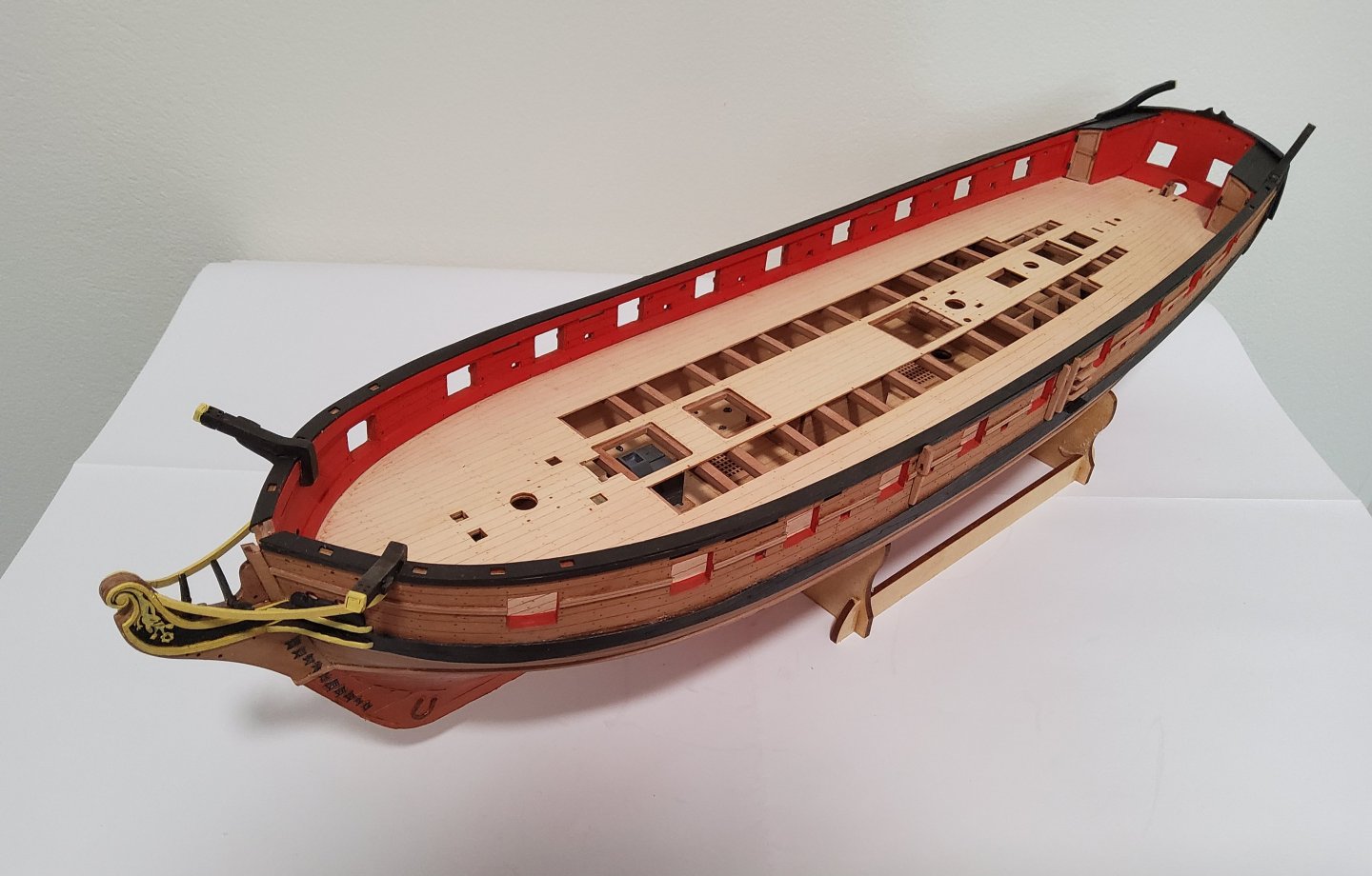
Some further progress. The hair brackets and the PE decoration that fits between the brackets were added to the prow. The upper and lower cheeks were added as was the hawse bolster. The brackets were very delicate and required careful handling, but fitted perfectly. The cheeks needed some sanding to get them to fit as they should. The bolsters needed quite a lot of sanding before they matched the existing hawse holes. The next bits to add were the prow knee and the "V" brackets that support the head rails. Chris very kindly included two sets of these (other than the knee) in case some of these rather delicate pieces were broken. Murphy's law was then triggered and the only piece I broke was the non-dupicated one. There was no chance of gluing the two pieces together, so each part was separately added to the prow along with its "V" bracket. There is a slight misalignment, but you need to know it's there to see it. The head rails were then added. And the davits have glued in place at the stern. Cheers

-
Found them.
-
Chris, You've not mentioned doors to the nose wheel well - are there any? One diagram does show a door but I can't find any other reference. Cheers, Richard