


Matrim
-
Posts
1,401 -
Joined
-
Last visited
Content Type
Profiles
Forums
Gallery
Events
Posts posted by Matrim
-
-
As always looking great

Joss
-
The Byrnes are brilliant machines. If you don't like the frames then it is better to redo as otherwise they will remain an irritation moving forward..
Joss
-
Looks good. On the camber you should overbend and give a considerable amount of time for the wood to dry - one of the reasons why I cut mine to shape - that way you are not worried about the bend changing.
Joss
-
Cheers Druxey, while I have the time I might as well utilise it to do the best I can
Joss.
-
Frame are in. Match up nicely (give or take a real life inch) with the gunports from the sheer, which is nice...
So as I contemplate my un-roofed extension filling up with torrential rain I can start on getting the body and sheer done and dusted next.
Joss.
-
Might be worth adding that to the database. Especially if it is relevant to the Byrnes one as well.
Joss
-
That is beautifully faired. Everything looks very smooth though the camera seems to be yellowing some of the shots (presumably the flash) which hides the beauty of the wood (which you can see in the more natural light ones)
Joss
-
Heal quickly. - It was not caused while working on the cross section I hope (tablesaws are very dangerous..)
Joss
-
Apart from the generic site guides
http://modelshipworldforum.com/ship-model-plans-and-research.php
no. Though the buttock lines are usually only drawn for the bottom most section of the ship where the standard waterlines do not provide enough information to create the shape.
Joss
-
Looking magnificent..
Joss
-
Brief post on scan placement. I find the easiest approach is as follows. Firstly ensure that the existing 'trace' is at 1:1 scale. The easiest way to do this is to use one of the provided 'figures' on the plans - lower deck length of breadth. This is easily seen on the plans as both Aft and Fore perpendiculars (vertical dotted lines) start from either end of this line. Work out the current distance between the two lines then divide one (I can never remember which) by the required figure (in my case 144ft so 1728 inches) to get the scale factor. This is then applied to one of the ratios in turbo cad (note whether you have keep aspect ratio on or off - if off then be aware that you are only adjusting one axis and will need to repeat for the vertical).
Length of breadth once correctly sized to 1:1
Once the trace is sized correctly we can attempt to match the next scan to the existing image. Firstly I would recommend cropping the image and possibly saving with a lower quality ratio. Most scanners contain far too much info and using the image 'as is' can contain extra junk that will slow your pc down. In my case I have turbo cad 20 64 bit so I have plenty of memory to play with. if you have less or an old pc then things will slow down if you do not do this first.
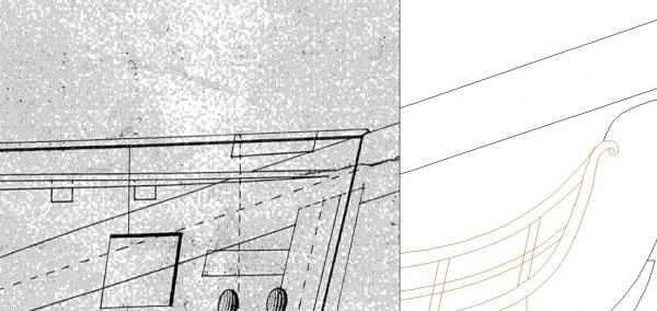
Anyway insert the image. Once done our first job is to straighten it. I find it easiest trusting the keel or rabbet lines. I straighten by starting a line at a point on the keel near the stern and ensuring this line is horizontal (press shift) plus dragging it past the end of the image at the bow side. Next starting from the same point (press v) I draw a different coloured line which follows the middle of the line I am using. Usually i start the line and just scroll to a point near the bow and place the line there then lengthen it past the image with the first.
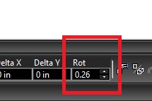
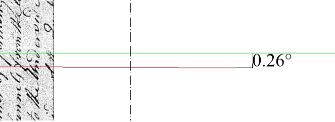
Now we can drop a horizontal constructor and measure the angle (dont do the distance)

this then can be applied to the rotate to straighten the plan.
Note if your keel line is not straight then you may need a different line.
Once this is done validate the plan 'stability' by putting a line or a vertical constructor over the two perpendiculars. This will give you a good impression of whether the plan is square of warps slightly at either end
This plan is good at the bow and slightly off at the stern
Our next job is to place the image over the trace. Ensure the trace perpendiculars exist well beyond the trace and you can use one of those to get the image 'close'
Once placed re-place a new horizontal constructor on the image keel line and then measure the distance between this and the actual perpendicular
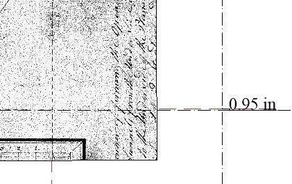
This can then be added/subtracted from the relevant axis (if using the keel it is the y if adjusting horizontally then you would be hitting the x) In any adjustment case look at the image when the adjustment occurs as it is easy to adjust the opposite way - this is usually blindingly obvious.
Once done on both axis I tend to validate the results by placing a horizontal line against an object which is clear on both plans and making sure when the image is made invisible that the line covers the same part on the trace.
You can also measure certain heights on plan and compare them to the actual plans to ensure you have no problems with any size adjustments.
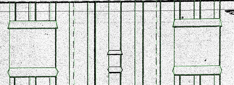
Finally you can start tracing the new image. One thing to remember is that the plan is unlikely to match exactly and you have to make decisions as to which plan is the master. For example I am treating my sheer plan as my primary plan but for the gunports the frame plan should take precedence as the gunports would be placed according to the edges of the frames so as long as the framing plan gunports are similarly placed to the sheer plan then there would be little difficulty. The other thing I do is to use the force vertical (shift again) and right angle tool to draw most of the frame lines. Most of the time these match quite well (for the square frames only!) and it allows me to validate both the framing plan and sheer plan at the same time.
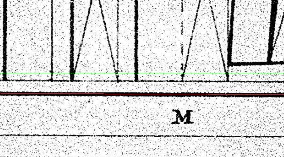
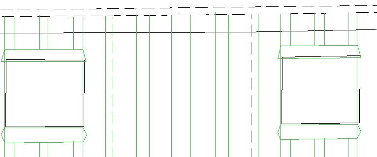
For example here is a shot of the rough trace of the framing plan over two central gunports
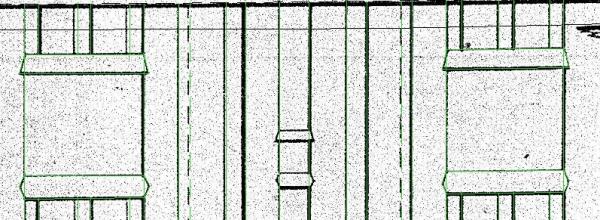
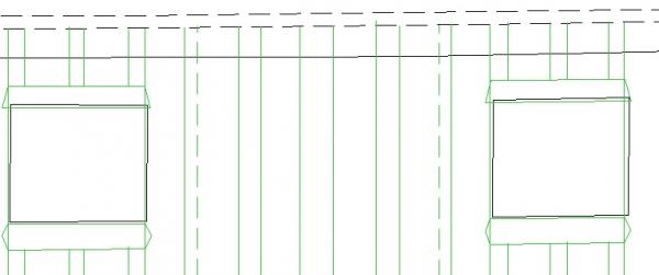
If I strip the image and include the sheer gunports you can see that though they are not exact they are very close. Also that the frames end points hits the dotted line of the sheer plan which is as expected as the barrier (probably not the correct term) moves up to that point and thus you would expect the frames to as well.
That'll do for now and I will go back to spending a week or so tracing over my next plan.
Joss
-
I quite like that jig as a way to provide horizontal reinforcement. I don't know if anyone else has mentioned this but when putting treenails in chad used an acetate strip (projector paper) with the holes marked in and one frame edge, that way you get the holes the same distance with ease.
Joss
-
Cheers Druxey, in the meantime I took a line from the forward perpendicular and compared the plan measurement to the traced measurement and they both came out at 325 inches (and this matched across all three plans and the class plan which I also have) so I am confident this issue was primarily in the scan conversion and the trace is correctly sized..
Joss
-
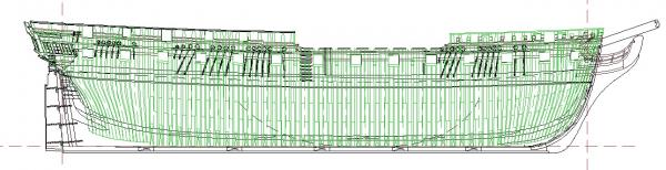
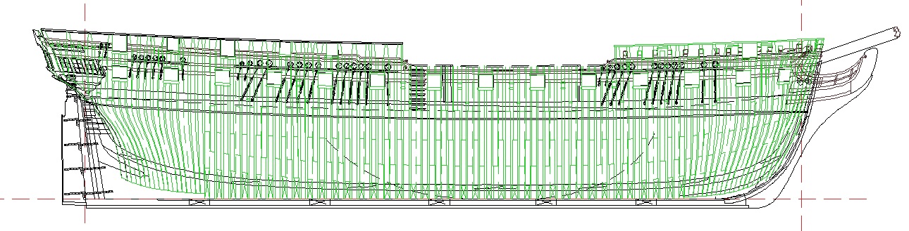
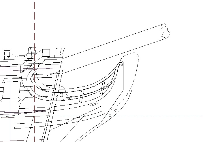
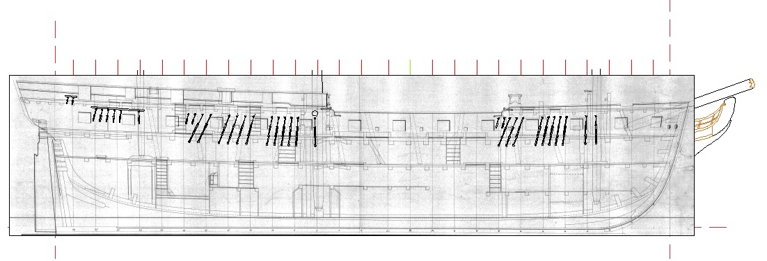
K, well time to cover the first stage of the reset. I was primarily unhappy for 2 reasons. 1 was almost unimportant and that was I did not think I had taken enough care in my first trace of the plan - nothing important note I had copied every important line but in the process I left lines of lesser importance (decoration mouldings, rigging supports) at either a very limited way or not included at all. As an example here we have my original trace
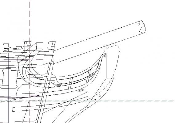
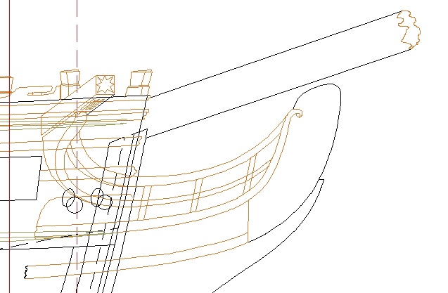
and here the new trace
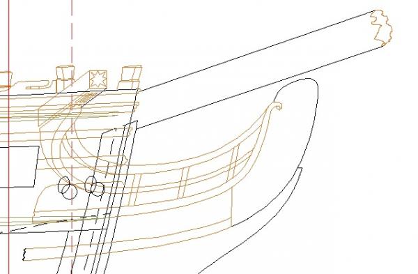
Hopefully you can see that more care has been placed on some of the less obvious things. The upper plan does contain some extra work on details (these will be added to the new later)
The second and more important reason was that when I first started I was concentrating heavily on the lines and not the other resultant drawings that I would need at the end. I vaguely recollect figuring that when I needed them I would just take the relevant info from the other plans. But when I got to needing them I found myself wanting all the data on my master plan so I could take it straight off. Basically I had increased in my cad confidence such that I was distinctly unhappy taking anything off the plans at all. This was the main reason to restart.
So I have now re-taken the lines (and used a better colour differnetiation structure now that I know what a lot of the lines are)
My next stage is to transfer the inside works and framing plans onto the same plan (using different layers of course). There may be differences between the plans but I will address them when I come to them. That way once I re-do the lines everything I need will be on one plan.
So confident in my plan I had the inner works and framing plan scanned and attempted to map that to the existing outline and instantly hit a problem. Basically the inner works were of a drastically different size to the traced plan. I almost broke into a cold sweat here thinking that either the trace is wrong (and perhaps the original plan) or the inner works is wrong. Either way it was bad. I then spent some time resolving the issue. First up I went back to the paper plans and measured the length of breadth and the height of the rear perpendicular to its highest point and did the same for the (0) station line. I then converted this to scale inches ( *48 / 25.4) to get the correct size. I then repeated this for the inner works plan and the framing plan.Fortunately they all matched bar an odd tenth of an inch or so.
This meant my plans were correct but one of the pc images was not. Armed with this method it was a simple enough task to measure the same heights on my traced plan. It was great news in that they matched.This meant the trace was good but the internal works had got warped somewhat in its transfer.
After playing with the measurements I eventually re-scaled the inner works over both axis and it matches closely. There is still an issue at the bow by a foot.but as the inner works is primarily there for the decks and keel/stern I am less worried about the mismatch here.
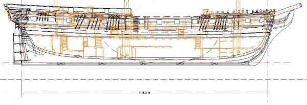
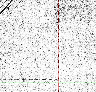
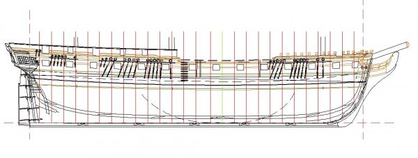
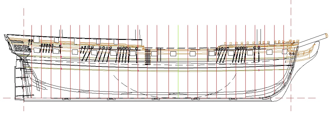
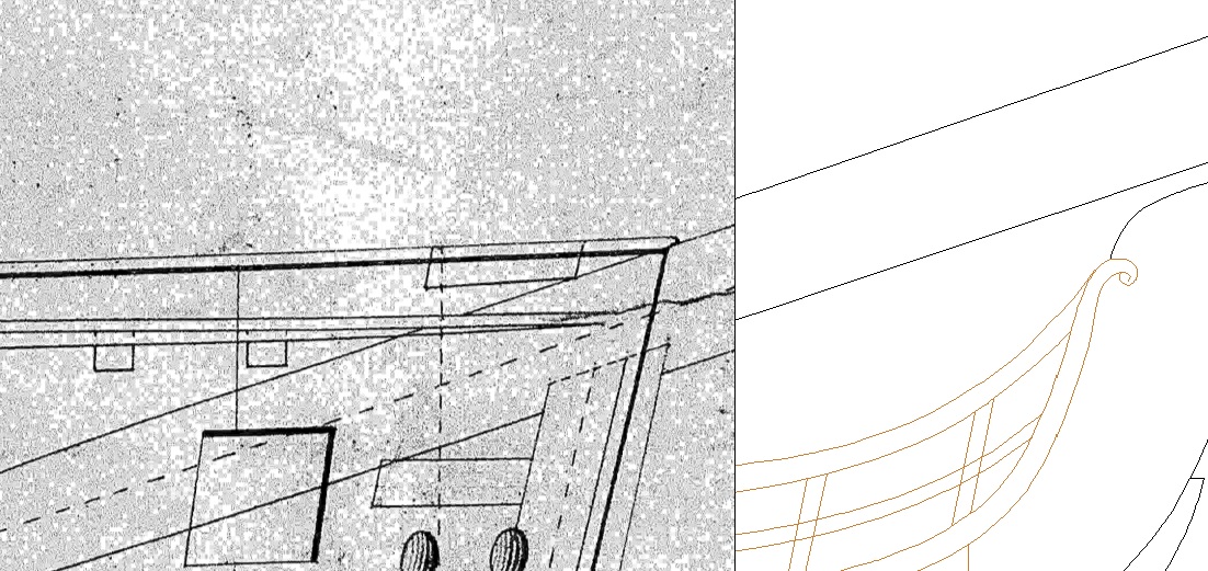
So here is the overall shot of the inner works plan. You can see the perpendiculars and for some reason the rigging showing from the underlying plan
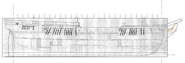
and here is the remaining problem area. As can be seen it is a distinct drop at the bow but not by much
This warp does appear evident on the paper plan so i suspect this is more an age thing than a further problem with the scanning process.
So next up is matching the inner works then repeating with the framing plan. After that I may re-use my original body plan trace.
Joss
-
Looks great, and well done for saving and re-posting all the old photos as well
Joss.
-
The colour combo is strong but not unpleasant. That wood looks almost ebony like though that could be the photo
Joss
-
-
i) could you please give me access to the drawings
done

-
Better to take your time than to rush and have to redo them as erm I did (twice)
Joss
-
Looking great, well done.
Joss
-
Thanks guys - at the very least I should be able to do a better job of logging those adjustments I am making to the original process.
Joss
-
Excellent, you are getting close to completion now as well..
Joss
-
Cool tool. Clever fix for the hatch - I did not realise they were in 2 halves? but if they were then that is a quite elegant solution to not having to recreate it from scratch again. Saying that I quite liked making the hatch though all my little slot bits kept losing 'teeth' which was irritating.
Joss
-
K, Just announcing a reset as I am not happy with my base plans. As with a lot of things ship building related the experience taken to get to this point has given me the knowledge to do the job properly (maybe that isn't quite correct - better may be the correct phrasing). I still have around 8 months before I was expecting to start building which will be plenty of time for a re-work.
So thanks for all assistance so far and all your supplied knowledge will help make my re-work better

Joss.


Triton by Pete38 - 1:48 - cross-section
in Cross Section Build Logs for HMS TRITON
Posted
Looks good, nice wood colour choice as well.
Joss