ships88
-
Posts
78 -
Joined
-
Last visited
Content Type
Profiles
Forums
Gallery
Events
Everything posted by ships88
-
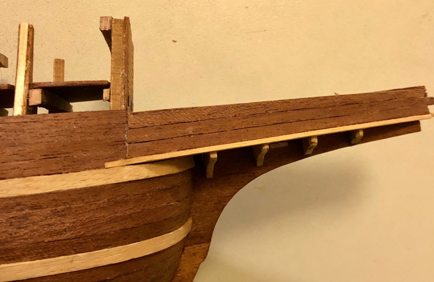
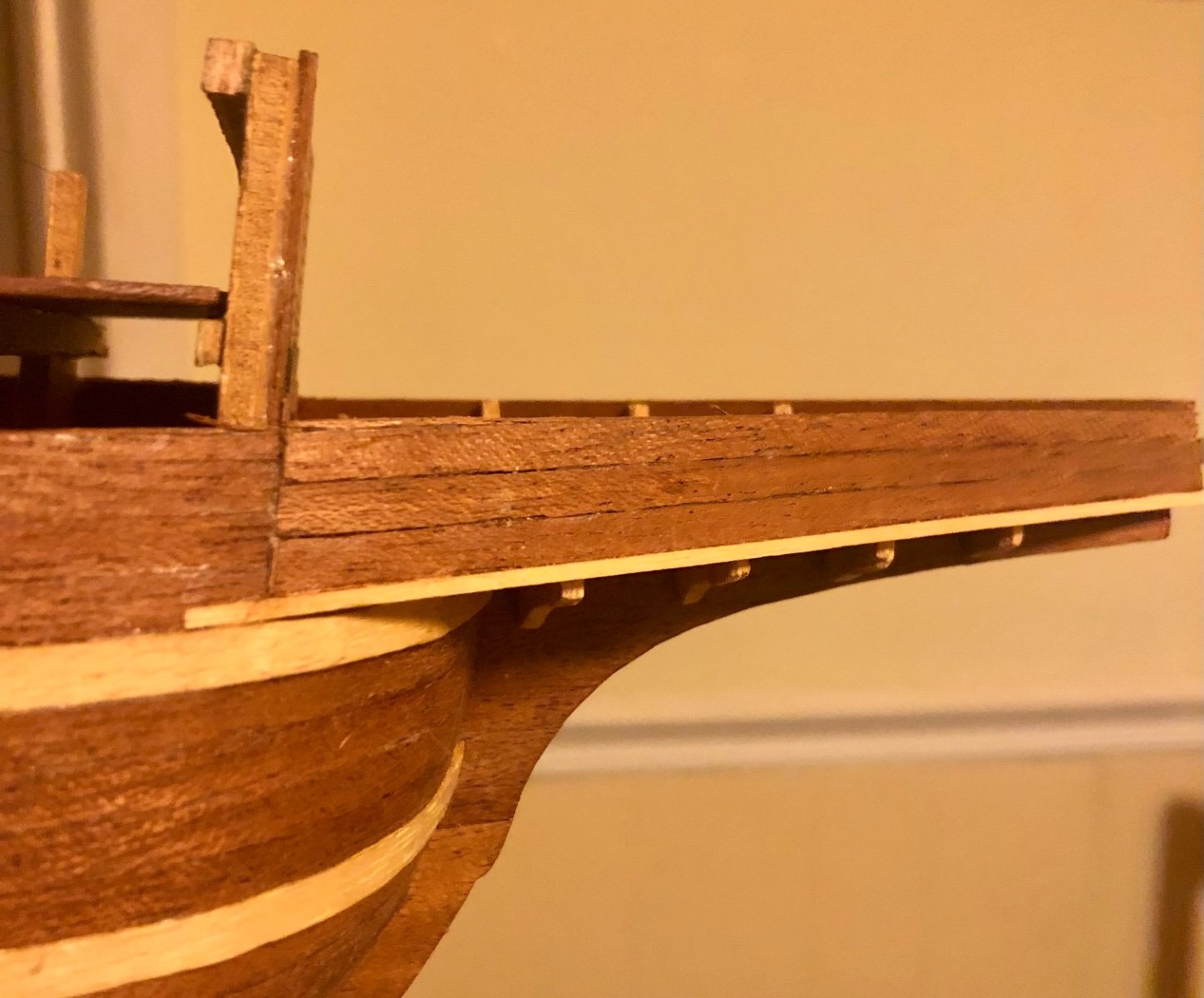
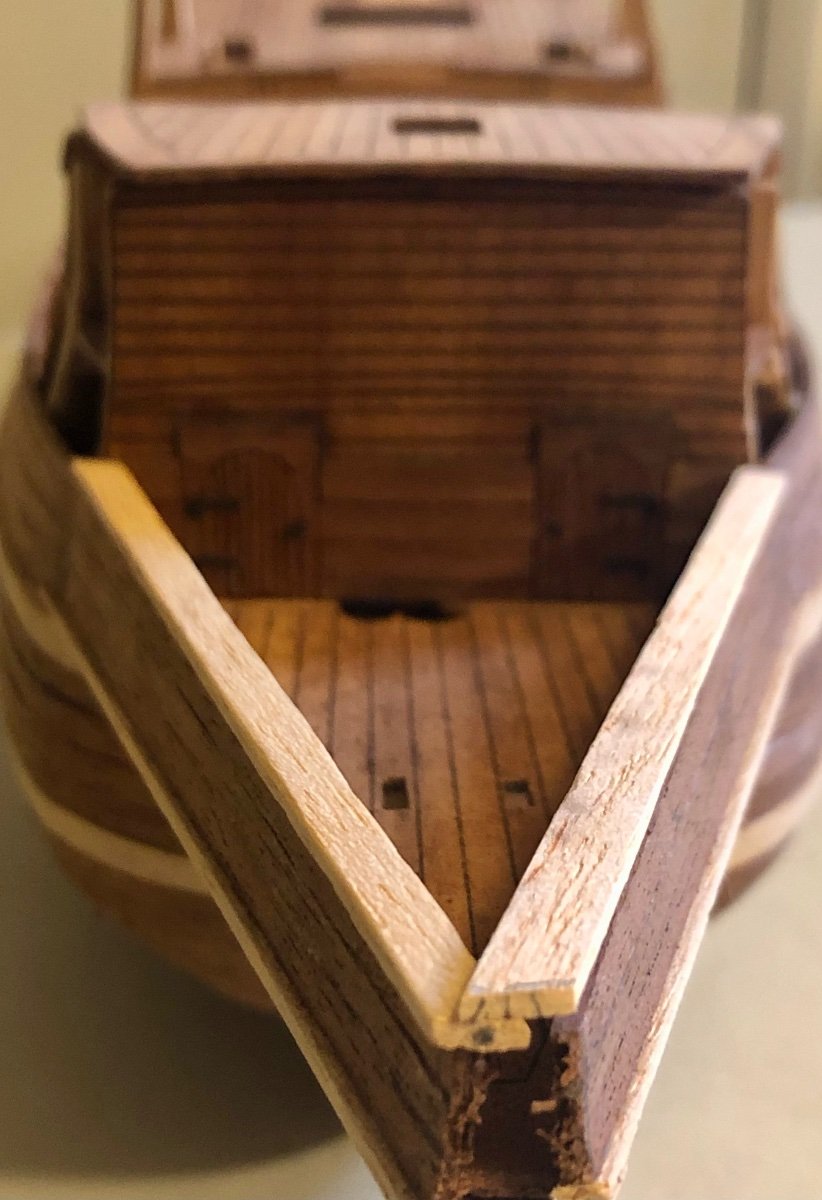
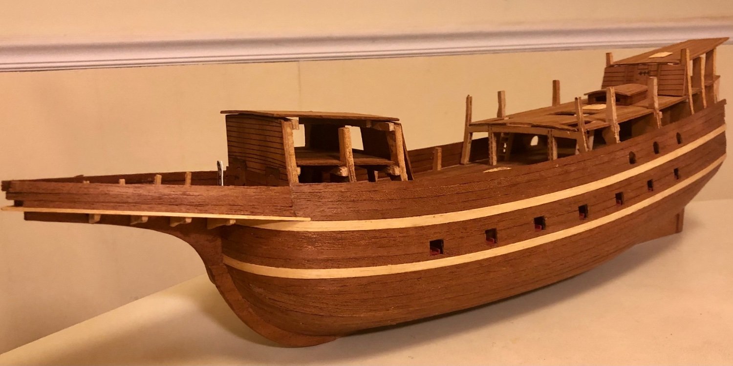
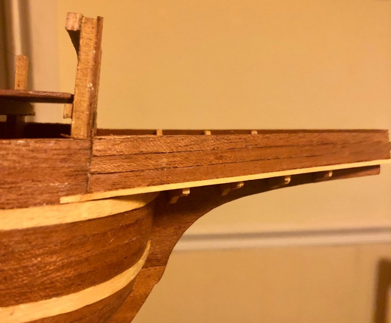
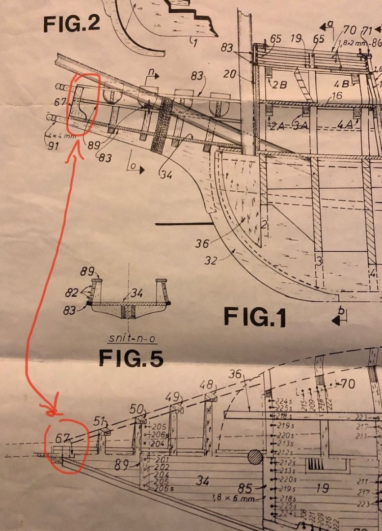
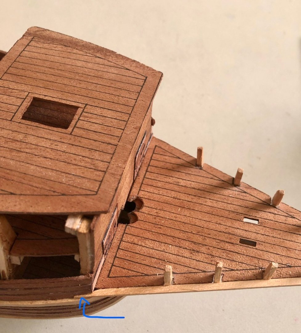
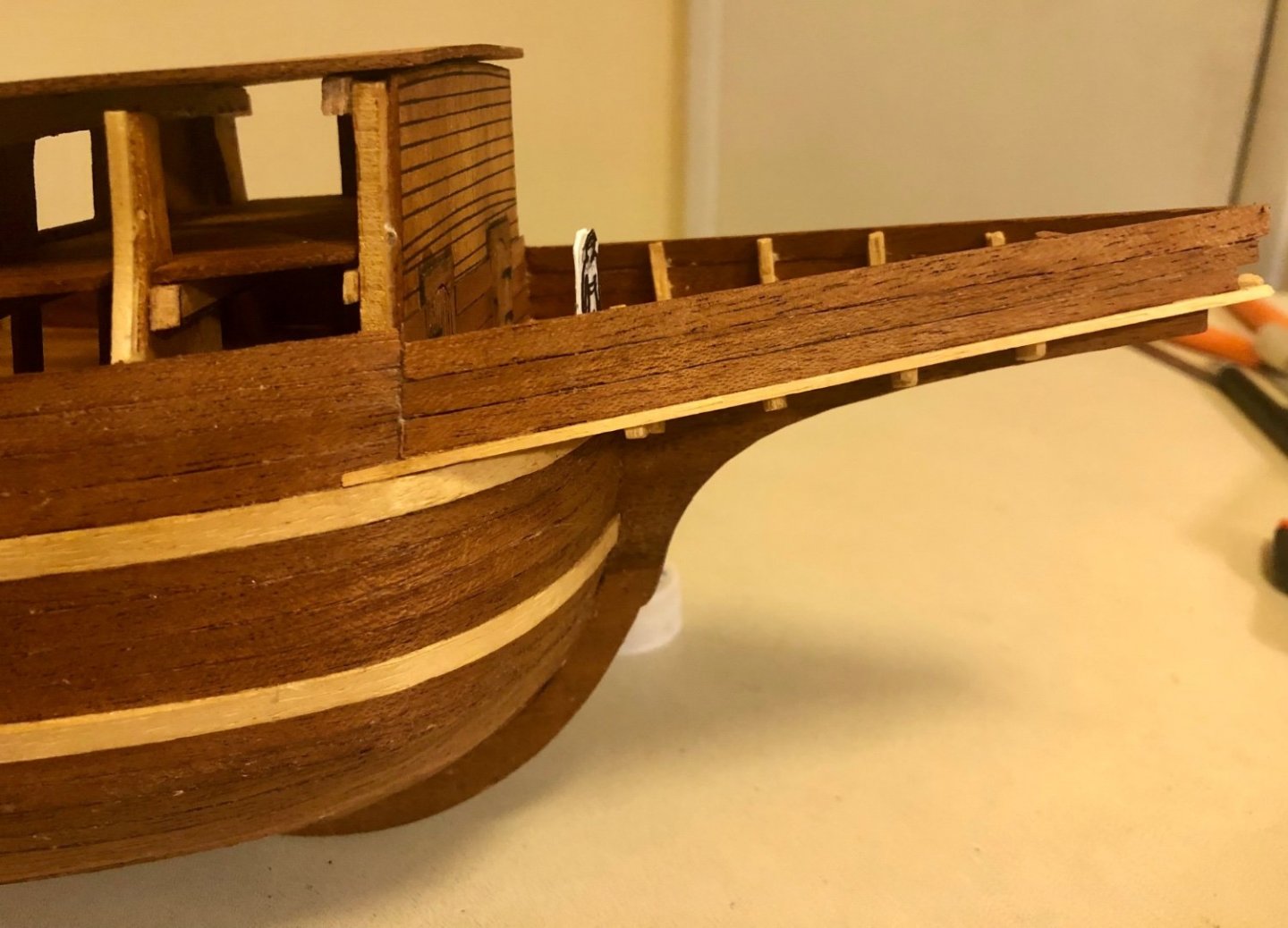
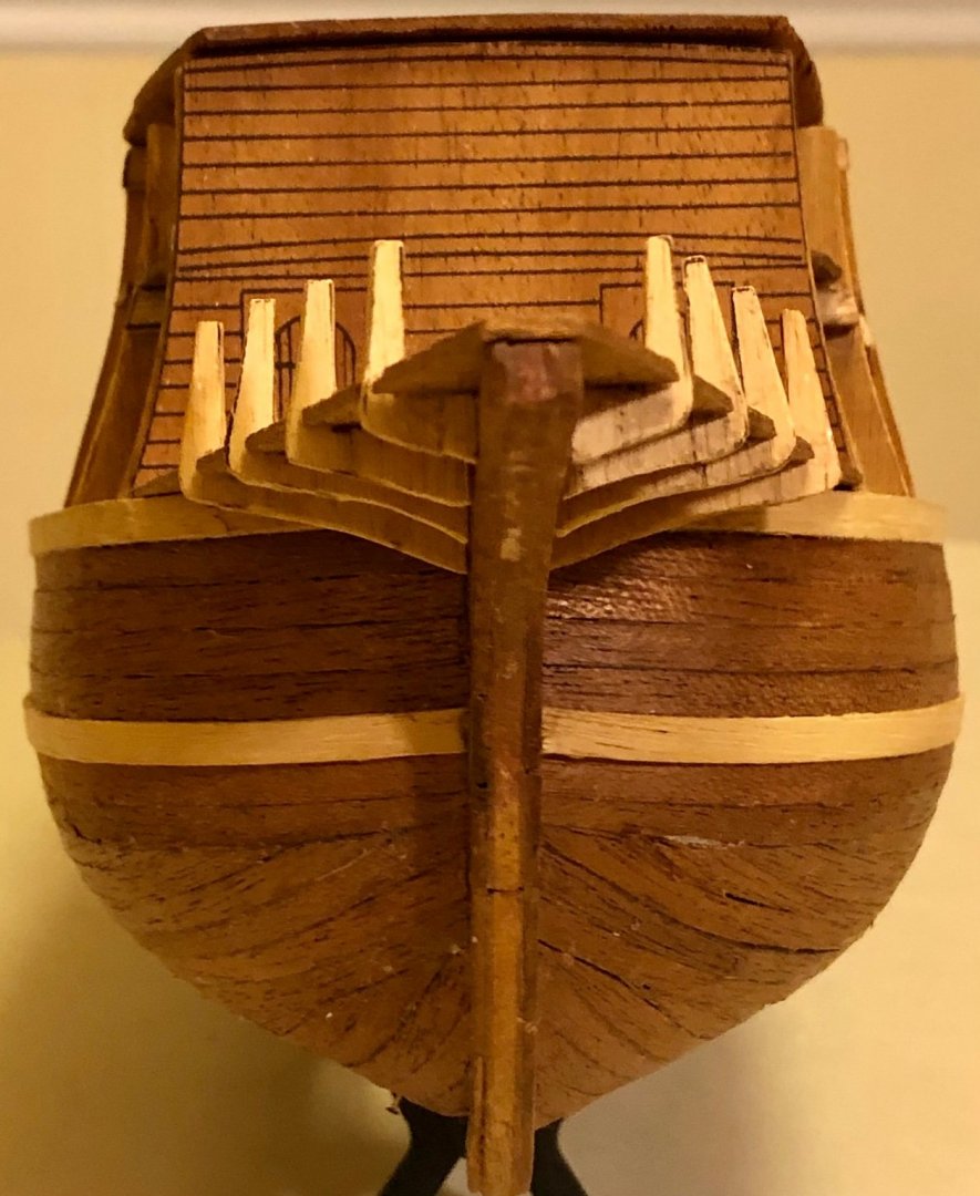
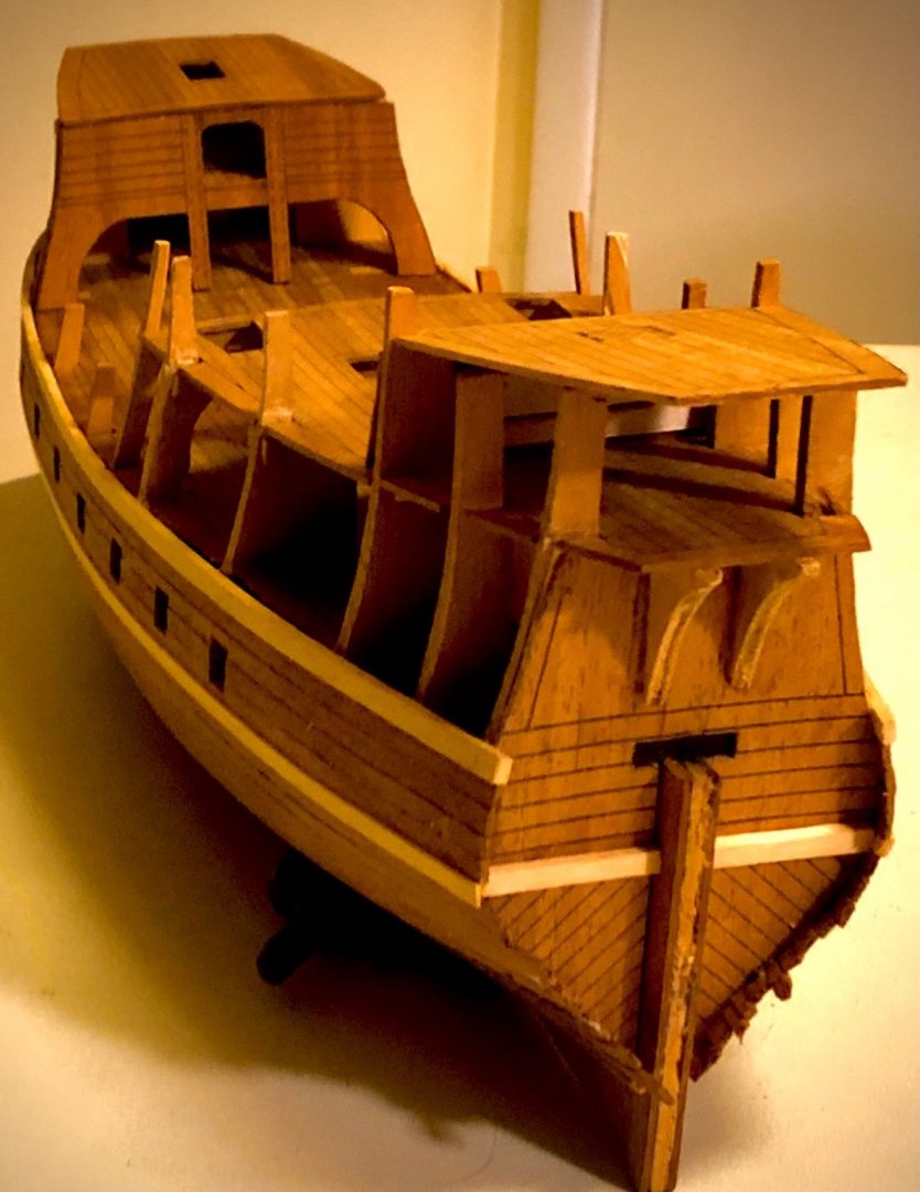
 Working on the head section, this is critical in determining the rest of the upper hull structure and hull lines. The starboard side head hull planking trimmed down to the correct height and slope. The forecastle planking is being cut back to match the trimmed head hull height & angle. This adjustment in height & line will be follow thru toward the stern. Note: the tapping diminishes at the start of the quarter deck post. This close up shows the height & angle differences between the trimmed Starboard and the untrimmed port-side head planking. An overall view of the trimmed line (Starboard side only, the port-side still need to be worked on next) A close up illustrating the mid ship hull line difference between the trimmed starboard side and the un-trimmed port-side height and profile. Test fitting of the head trim stakes. The port-side stake corner was rounded in compared to un-rounded yy side stake. Notice the frontal shape of head, it forms a trapezoid shaped. How the two head trim rails supposed to come together and finished off depended on stake #67. There is not much information about this important component other than what is shown on the drawing. It was deducted from the drawing it is 4mm thick. There are no supplied wood in the kit to account for it. It will need to be created from gluing numbers of pieces of wood together then shaped to match the drawing profile. This need to be installed first before installing the two head trim rails.

- 58 replies
-
- 2
-

-
- Spanish galleon
- Billing Boats
- (and 1 more)
-
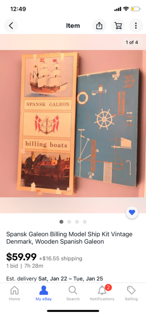
FYI. In case anyone wants to build this kit (which is very hard to find now a day), there is a complete kit w fittings (mine didn’t included this) for sale on Ebay ending in 7 hours. https://www.ebay.com/itm/Spansk-Galeon-Billing-Model-Ship-Kit-Vintage-Denmark-Wooden-Spanish-Galeon-/234365391734?mkcid=16&mkevt=1&_trksid=p2349624.m46890.l6249&mkrid=711-127632-2357-0
- 58 replies
-
- 1
-
-
- Spanish galleon
- Billing Boats
- (and 1 more)
-
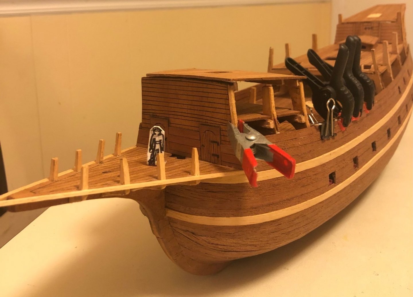
Thanks Patrick for the heads up. I will check out the build log. PS. I have the Aeropiccola Golden hind kit and will build it sometime in the future. ======================== A few dilemmas arise after installing the 4th planking above the upper rubbing stake. It is hard to judge the exact heigh and curvature at the waist area. There is a trim stake running from the head all the way to the stern. The drawing and instruction booklet did not give enough direction on the construction sequences (there seems to be a lot of inter- dependencies). After studied the drawing numerous times, it was deducted the most logical place to start is from the head, then work backward toward the stern. The lower trim stake for the head planking installed. The stake tills slightly upward, which will align the head planking in parallel to the forecastle silhouette angles. The lower head trim stake actually run into the hull upper rubbing stake. This transitions and integrates the two together. Both head trim stakes installed. The head bulwark stake had to be trim back quite a bit to allow the trim stake to lay flush against the head deck. A frontal view. The head plankings installed. The over hang portions will be cut off later. Noticed the head planking tills inward. They aligned up to the forecastle’s angle profile (almost). The head planking height reduce down towards the front. Once it is trimmed down to the correct height and angle, the head rail trim will be added. This will allow the remaining trim strip height from the forecastle, to the hull waist section, all the way out back to the stern to be calculated, worked out and installed. Will update…
- 58 replies
-
- 4
-
-
- Spanish galleon
- Billing Boats
- (and 1 more)
-
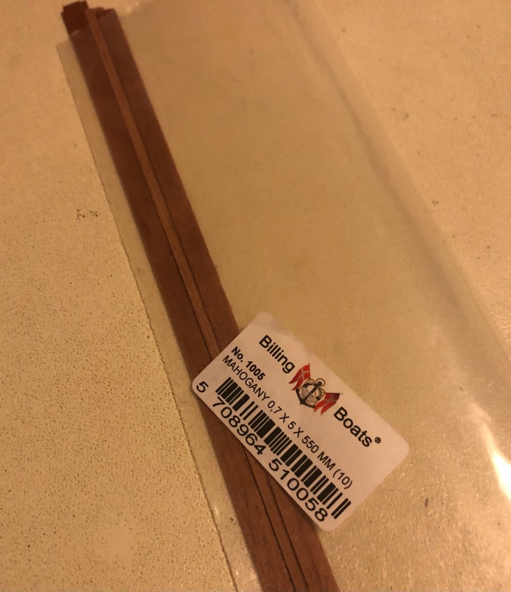
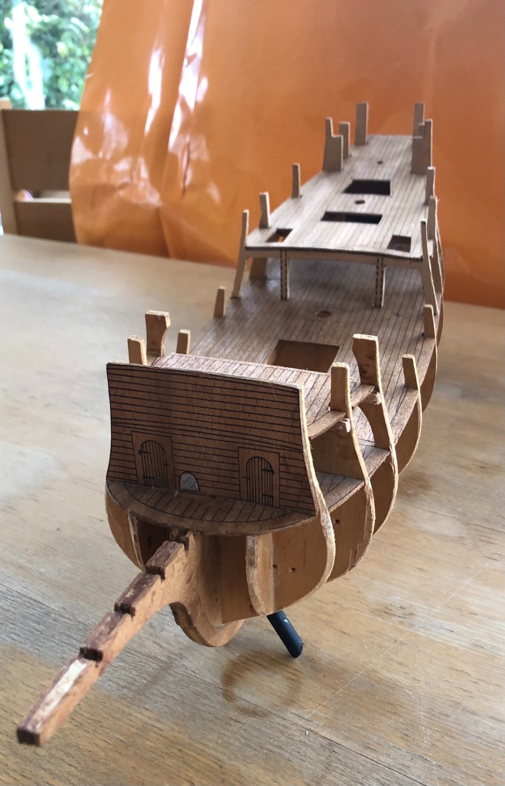
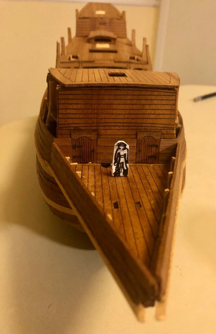
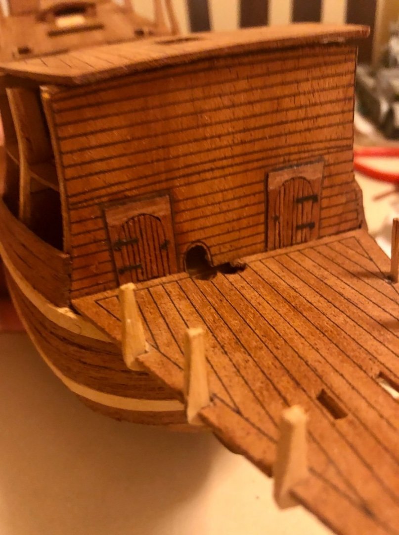
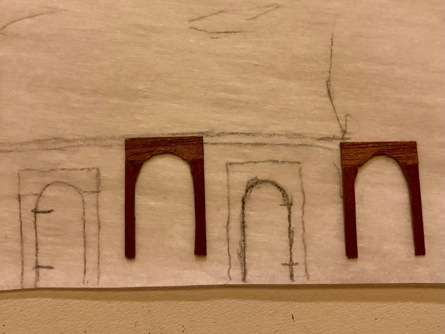
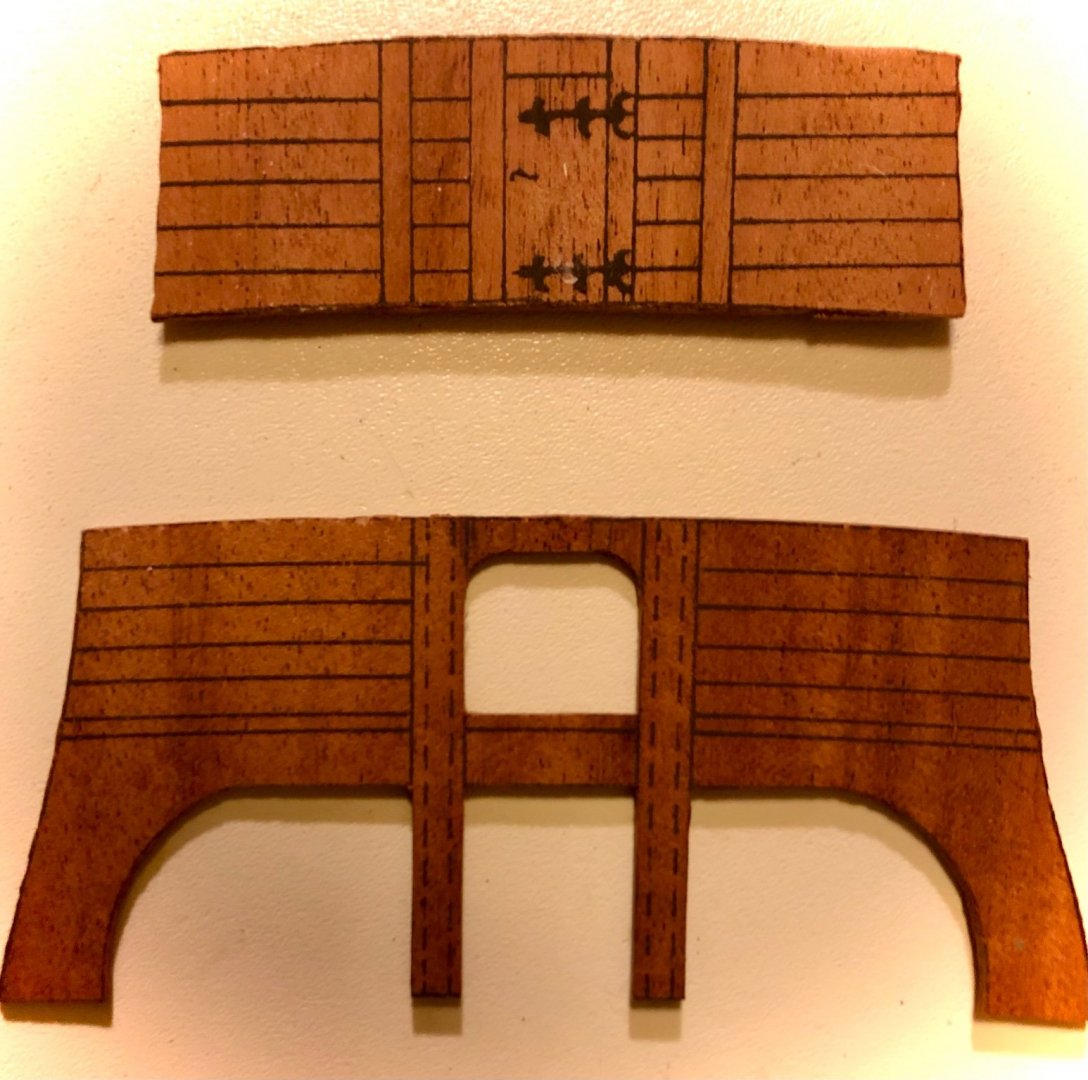
Thanks Backer for the build references. Greatly appreciated! Btw. Was the Golden Hind drawings by Aeropiccola by chance ? I have to first plank over the printed forecastle forward facing panel in order to proceed w the upper hull planking. By luck I found some Billing Boats mahogany planks that I brought years ago for my other Corel Hms Peregrine build. They will do nicely planking over the printed structure areas. Go figure 😁😁. Traced out the forecastle doors w wax paper. Shaped and created the two door frame from the thin plank. They consist of three pieces each, a header and 2 door jam studs. Those took almost 1 1/2 hrs. Trimmed the 5mm thin planks down to 1.5 mm with strips then cut to shape and length. They took a lot of time - 2 1/2 hrs. The door hangs and handle were added afterward. Those are heavy black construction paper cut outs. The gammoning holes were cut out on the head deck and set in place.

- 58 replies
-
- 1
-
-
- Spanish galleon
- Billing Boats
- (and 1 more)
-
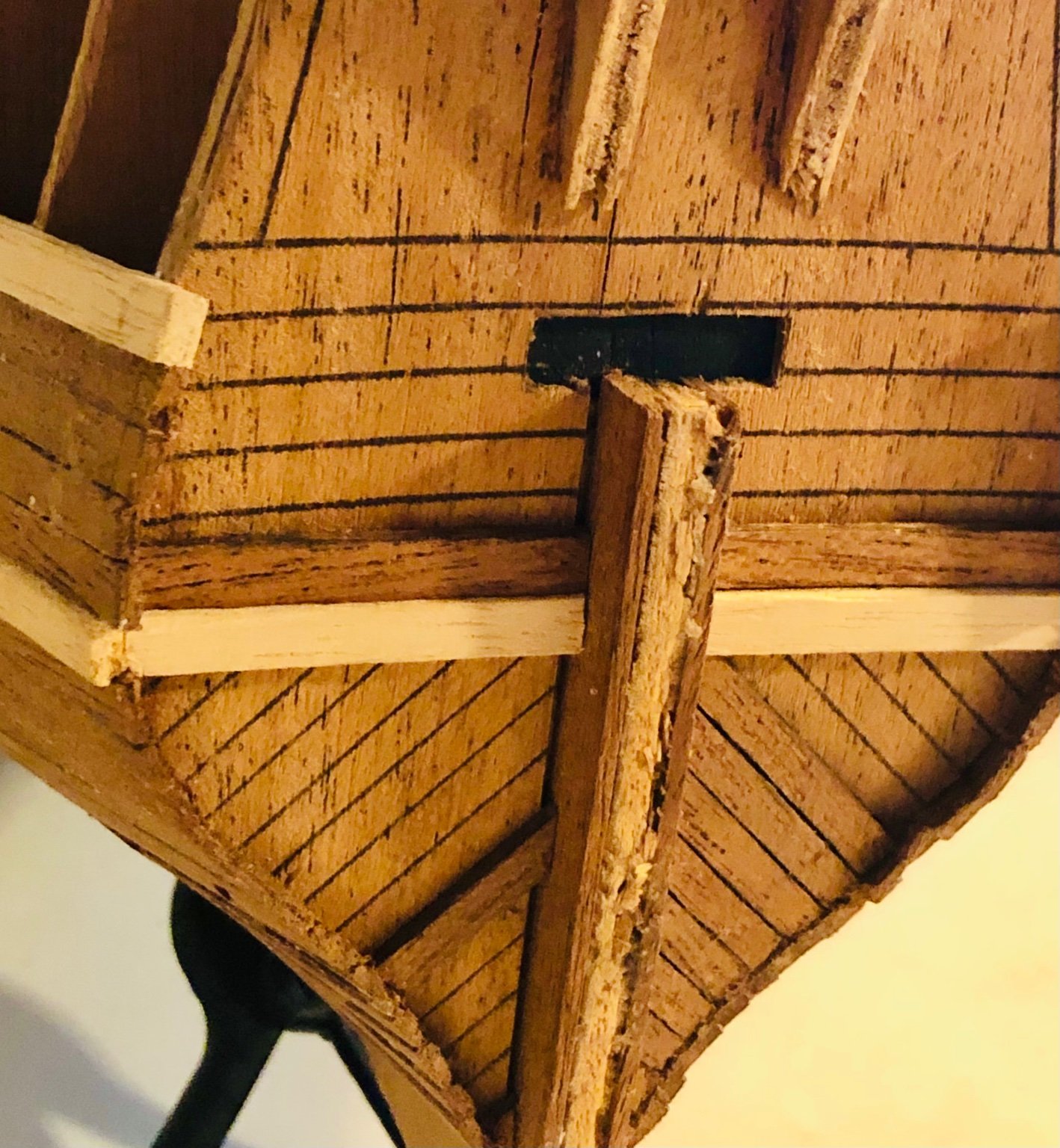
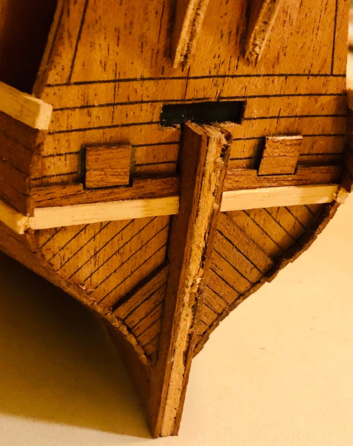
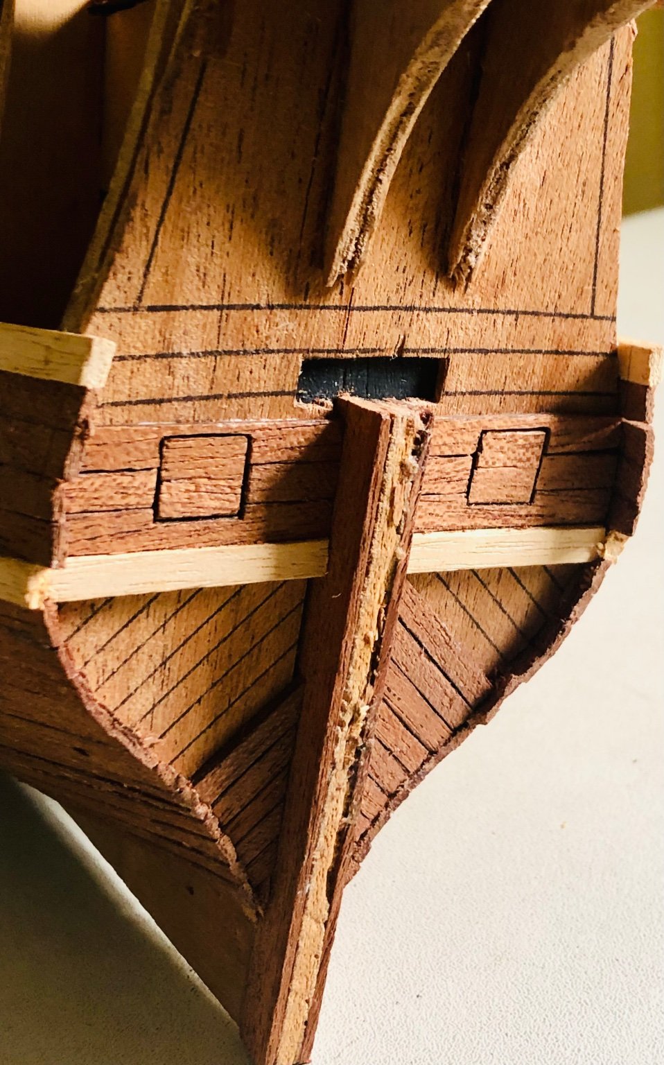
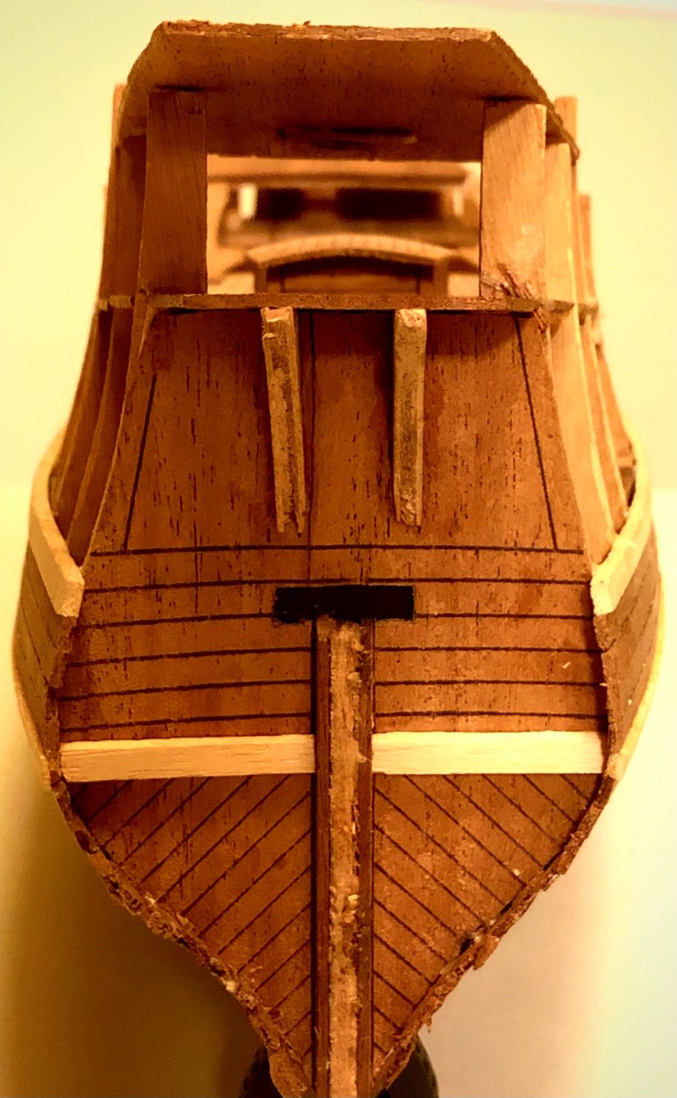
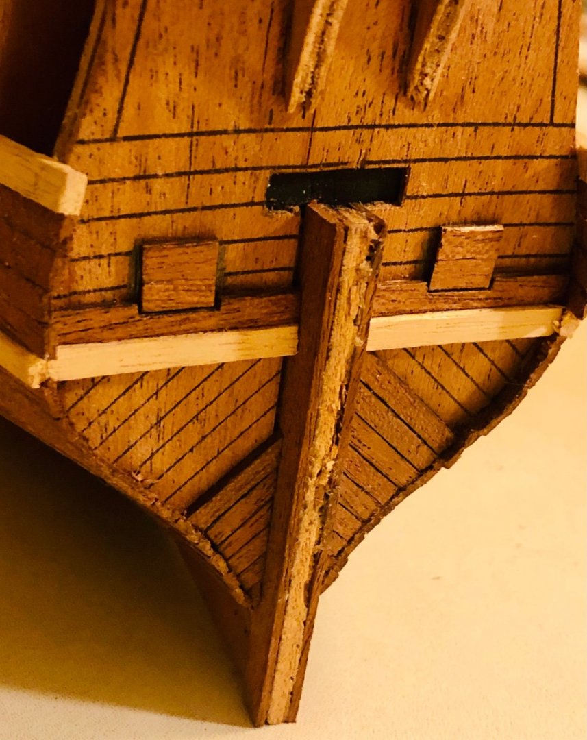
Thank Paul for the suggestion. There are two considerations for lowering/shorten the stern post for the rudder - tiller opening. They seems to out weight the modification justification. (1) You are correct about the modification will alter the rudder profile (the fix likely will cause a lot more distortion to the over all ship profile) (2) The lowered stern post /rudder opening would technically resulting in the tiller swing into the path of the two stern chase guns and their crew’s heads.
- 58 replies
-
- 1
-
-
- Spanish galleon
- Billing Boats
- (and 1 more)
-
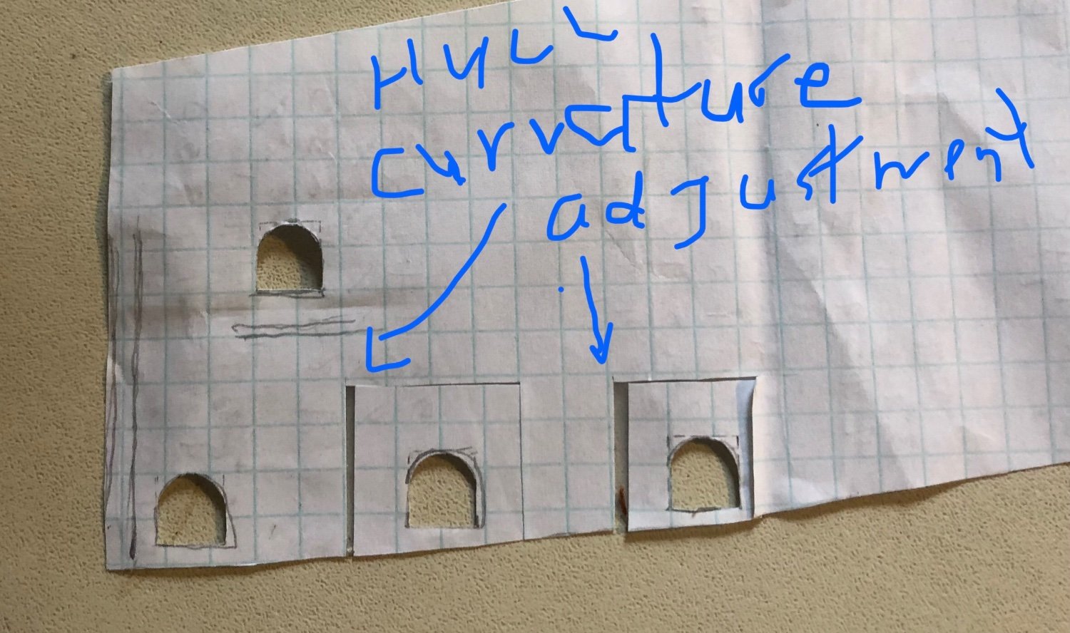
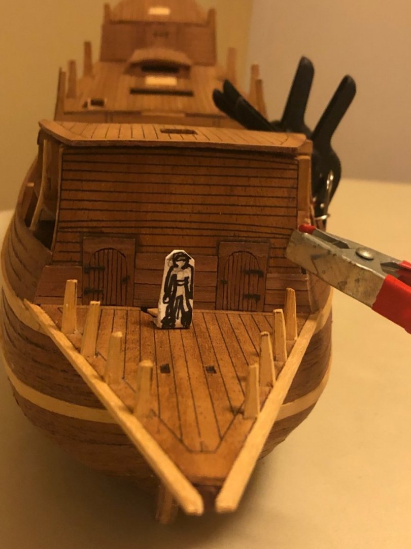
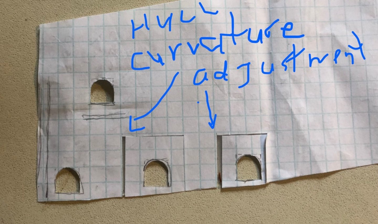
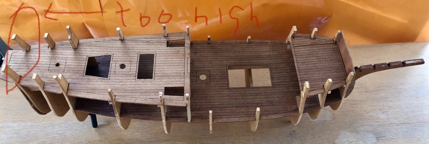
Complete 3 layers of the planking above the first hull wale. The plan calls for 4 layers of 5mm width planking. This created a big discrepancy between reality versus the plan (there is only approximately 2 mm height left at the mid ship area (see below pictures). This height is important since there will be a highlighting light wood strip running from the head rail all the way to the stern. Need to think about which route to proceed. Made a paper template for the upper hull gun ports against the plan drawing. Added spacing for hull curvature adjustment. 2 items need a decision: 1. Add upper hull stern wale ? My gut feeling is not to since it will overlap over the rudder- tiler opening. This would not make any sense as wale is installed to add strength to the hull structure. 2. what plank size (width) to use for the forecastle and the poop deck planking ? Based on the scaled sailor cut out, i think it should be be the wider plank (4-5mm). What does everyone think ?


- 58 replies
-
- 6
-
-
- Spanish galleon
- Billing Boats
- (and 1 more)
-
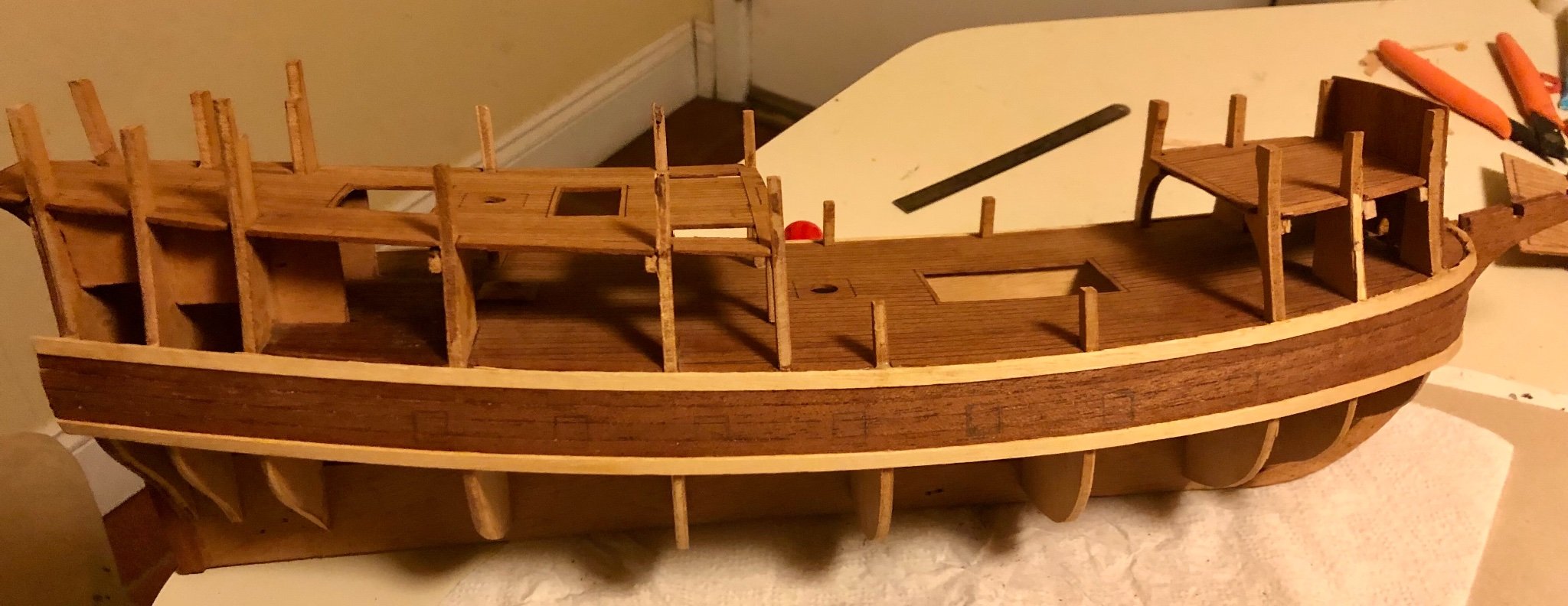
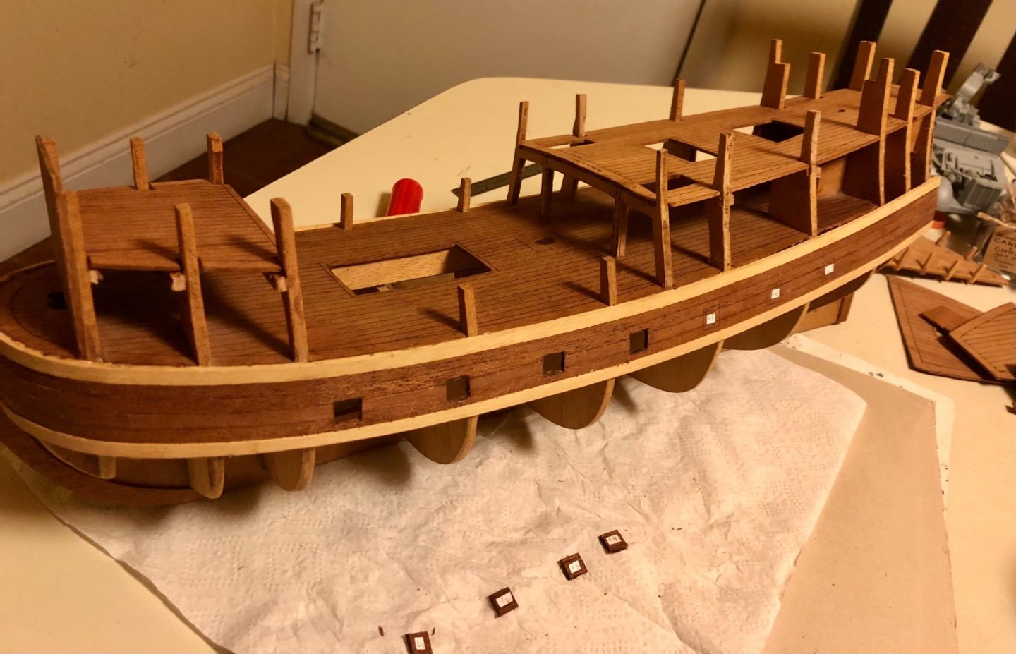
Installed the 2 outside stern pieces to the upper hull. Those pieces were shaved slanted to fit the hull curvature. Scratch built the main deck ladder. It was built using my favor crap wood (two different sizes of coffee stirrers). Test fitting the ladder. Made a 1/66 scaled sailor cut out to check for proportional correctness. All mast coats were all shaped and installed. I don’t believe they are the correct shape (should be circular shape instead of square). Oh well,,, building as indicated in the drawing. There isn’t much available information on Spanish galleon to confirm one way or the other. Started the first planking above the deck. I had to add spaces in three places to ensure proper backing and curvature lengthwise.
- 58 replies
-
- 2
-
-
- Spanish galleon
- Billing Boats
- (and 1 more)
-
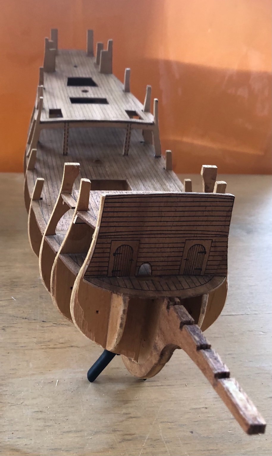
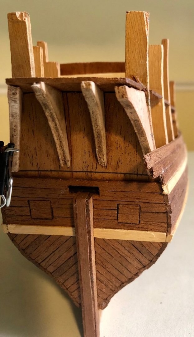
Thanks Backer and Paul for your feedbacks and inputs. They are very helpful and greatly appreciated !! Working on the stern area. Starting adding the stern planks and cutting off the hull over hangs in conjunction. Added two stern gun ports. Planking surrounding the gun ports completed. The gun port hinges, gun port door lifting ring and rope will be added at the end of the construction to avoid damages. Wishing all a happy holiday season !!


- 58 replies
-
- 3
-
-
- Spanish galleon
- Billing Boats
- (and 1 more)
-
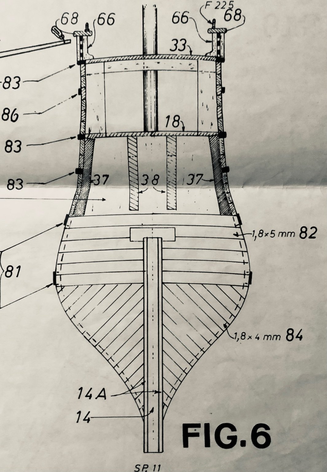
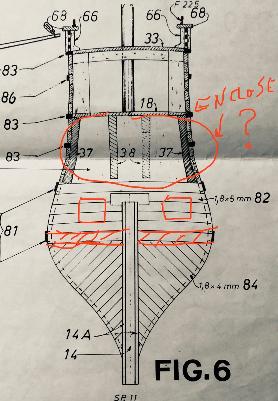
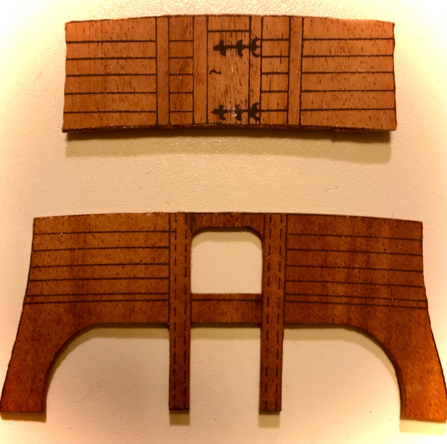
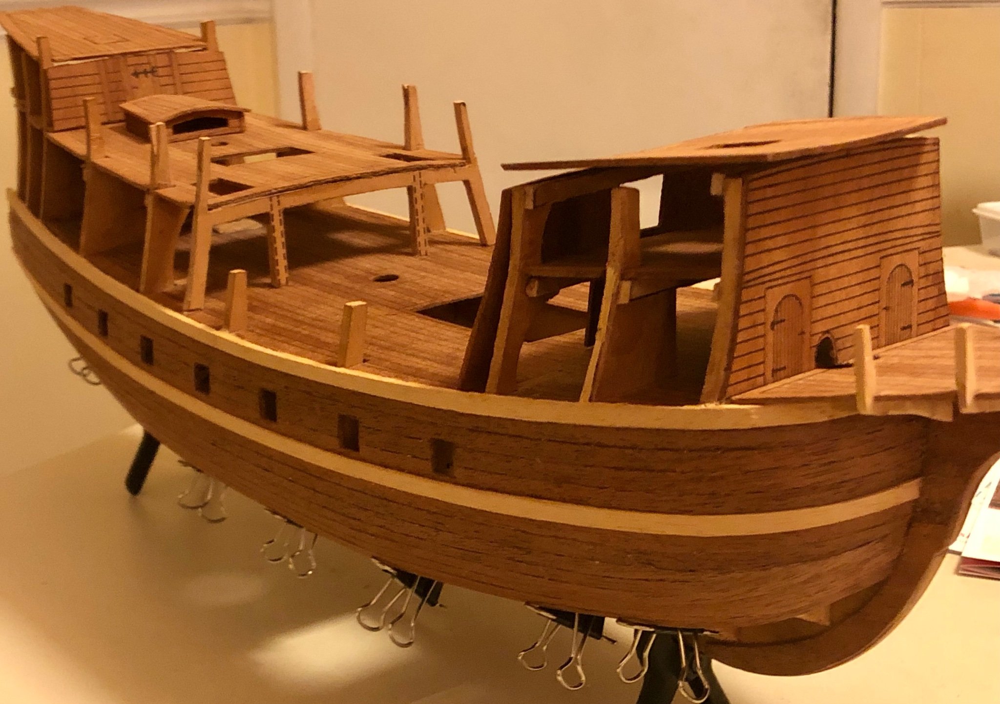
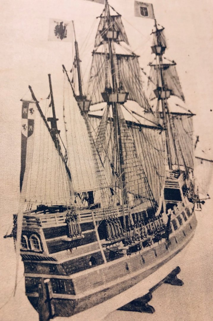
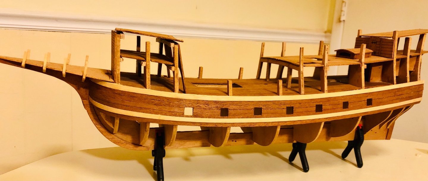
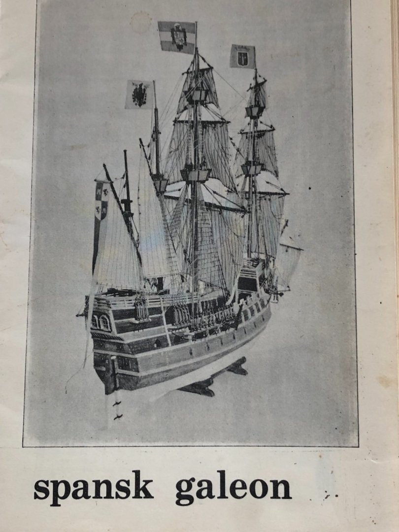
Thank you for your interest and support. Hope you are enjoying the build progress. The hull planking is almost completed, 2 -3 rows left close to the keel remains. A lot of scrapping and sanding of the hull still need to performed. All the gun carriages are installed in place. The over hang hull planking will be trimmed flush against the stern planks (after they are installed). Stern wale added (not in the Billingboats drawing) Looking and planing forward to the next phase of the build and there are few decisions need to made as to what to proceed with. The Billingboat’s plan for the stern area detail is very vague at best. I think they did it intentionally to leave it up to the builder to decide as this model is a “generic Spanish galleon” of the era. The finished model galleon picture on the cover page of the written instruction booklet shows 2 lower heavy gun ports and 2 lighter gun ports at a higher deck level, and a enclosed stern wall. I think the 2 light gun ports maybe too much (due to the width of the stern, and compared to the number of guns installed hull length wise on the same level). The other decision is to add individual planking, doors and hardware to the printed upper hull wall structure or just affixes them in place as is ? What does everyone think ? Please comment with your suggestion.


- 58 replies
-
- 2
-
-
- Spanish galleon
- Billing Boats
- (and 1 more)
-
Just update pictures on the planking progress (not very exciting). The lower hull planking should be done by another week or two, then the more exciting upper hull construction will start.


- 58 replies
-
- 3
-
-
- Spanish galleon
- Billing Boats
- (and 1 more)
-
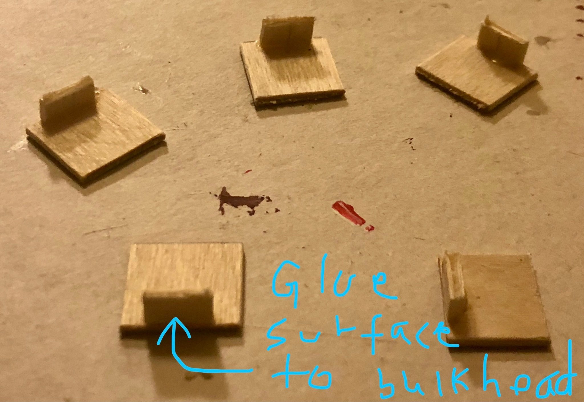
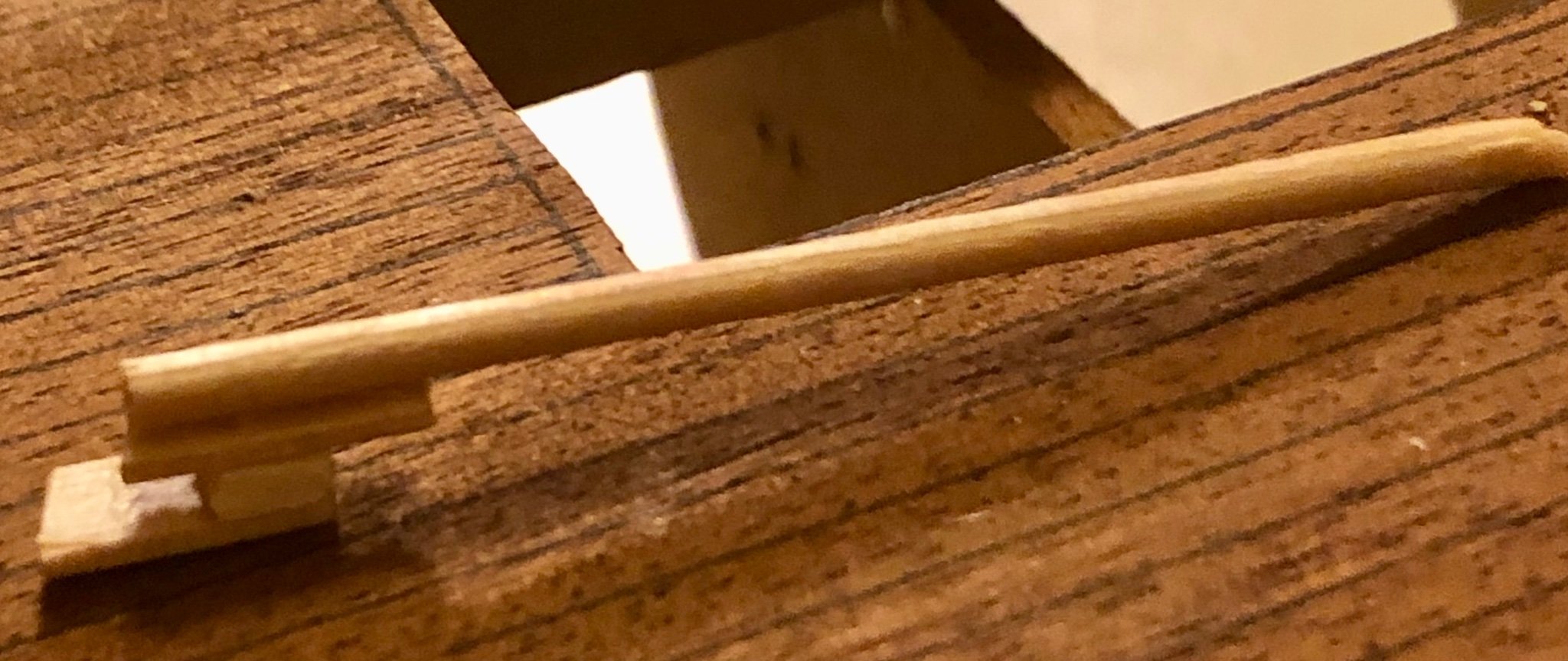
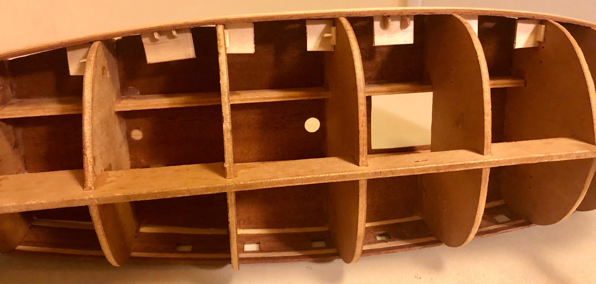
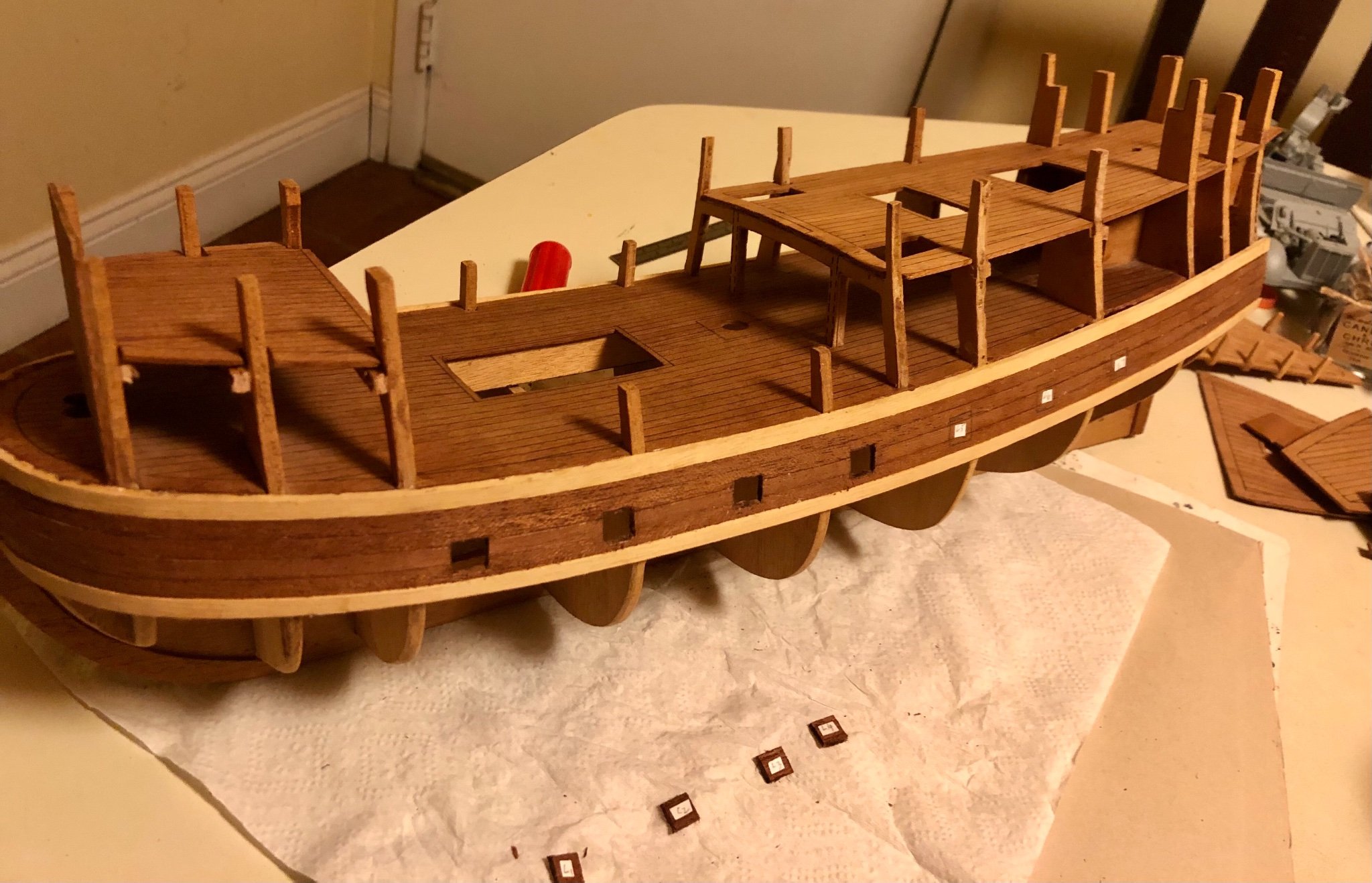
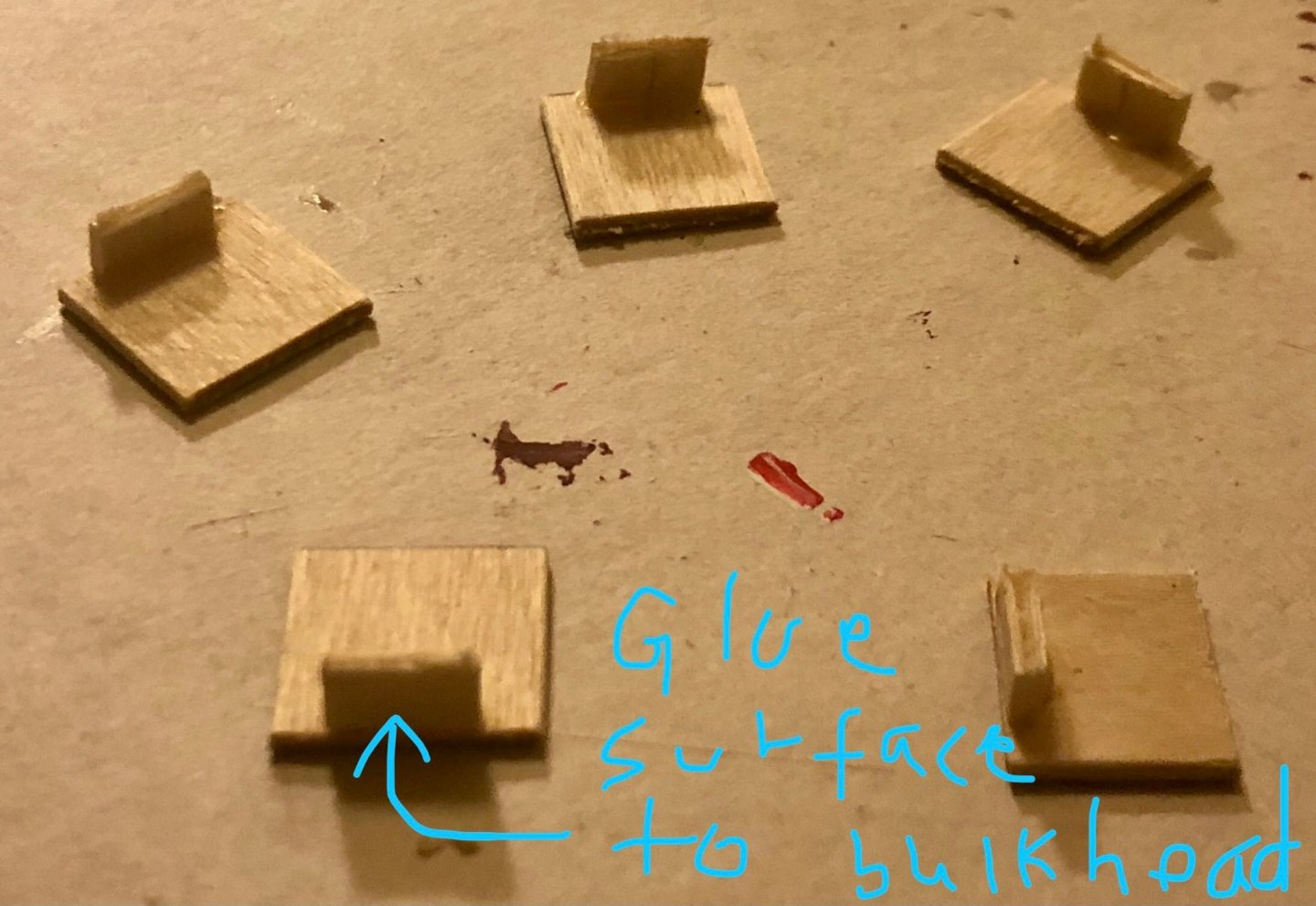
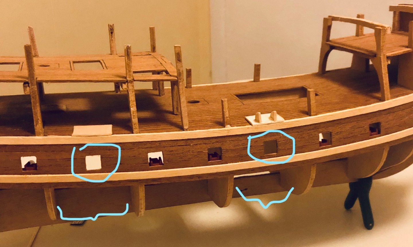
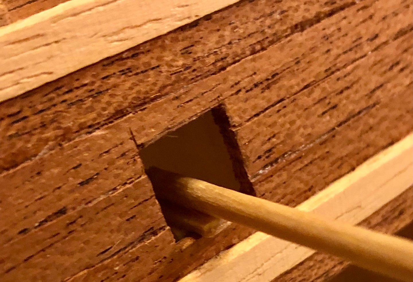
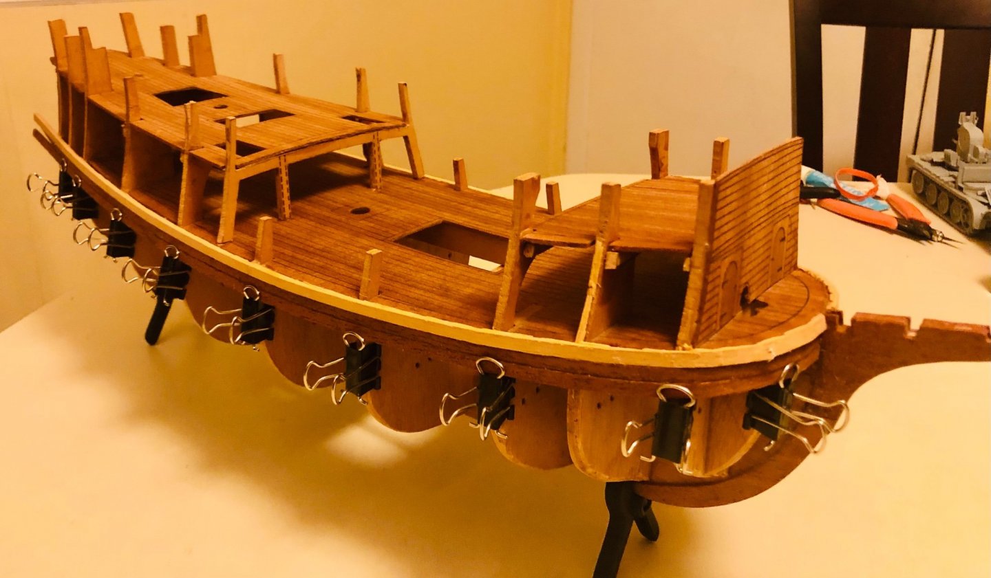
Five out of the seven gun ports are located adjacent to a bulkhead. The gun carriage deck piece will be glue to those bulkheads. A piece of wood is glued perpendicular to the deck piece to serve as the joining surface. Gun ports #3 and #6 are located in the mid point between two bulkheads and required those to be glued to the hull directly. Those deck pieces were shave off a bit on both end to confirm to the hull area they are to be positioned in. Two support wedges were added underneath to increase gluing surfaces and provide vertical supports. Made a simple deck positioning jig to aid leveling where the deck should be placed. The jig’s rod is approximately where the gun would be out of the gun port. This is what the carriage deck looks like from underneath. Test fitting of the gun carriages. On to the other side and repeat the same,,,,


- 58 replies
-
- 4
-
-
- Spanish galleon
- Billing Boats
- (and 1 more)
-
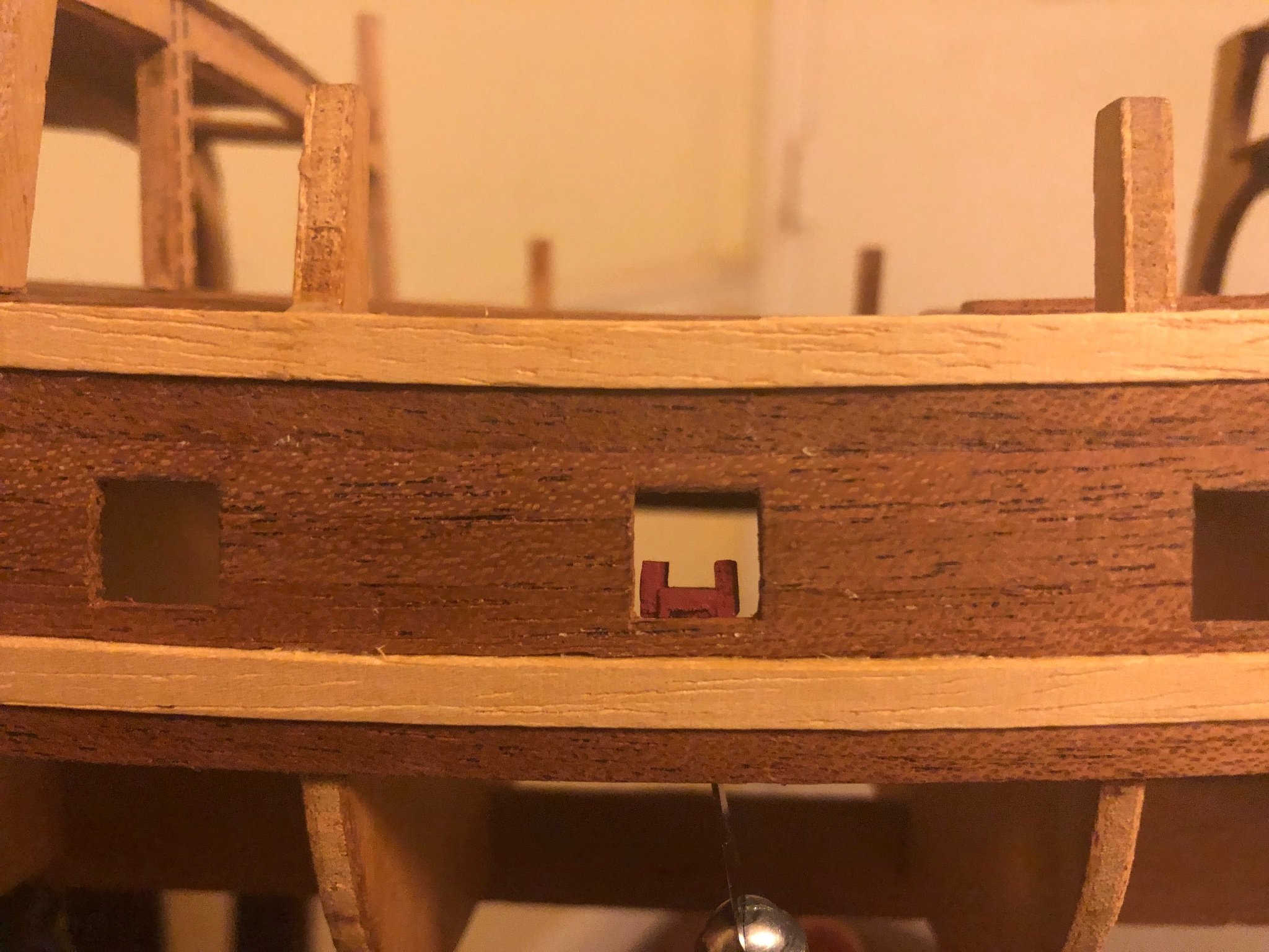
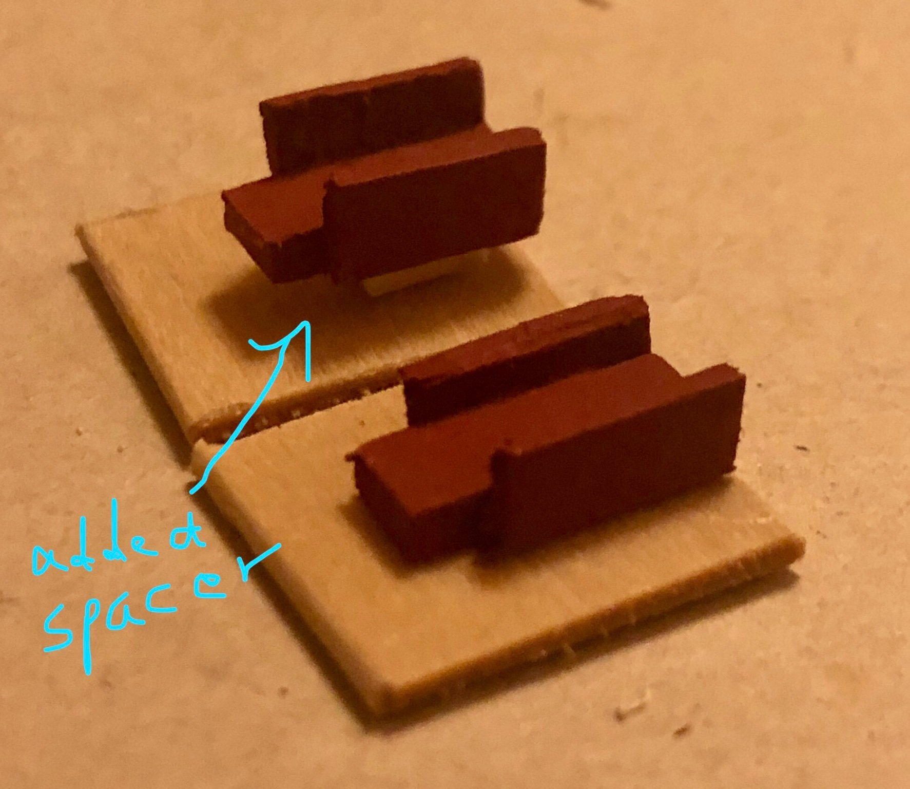
Cut out deck pieces for the placing the gun carriages in the gun ports. As the Billing boats construction plan doesn’t have “real” gun ports installations, everything is by trial and error. Test shot of the gun carriage in the gun port. Looks fine, but realized a spacer will need to be added underneath the carriage (aka, to account for carriage wheel height), otherwise the deck piece will be flush with bottom of the gun port opening (awkward position). space added comparison to the original.


- 58 replies
-
- 5
-
-
- Spanish galleon
- Billing Boats
- (and 1 more)
-
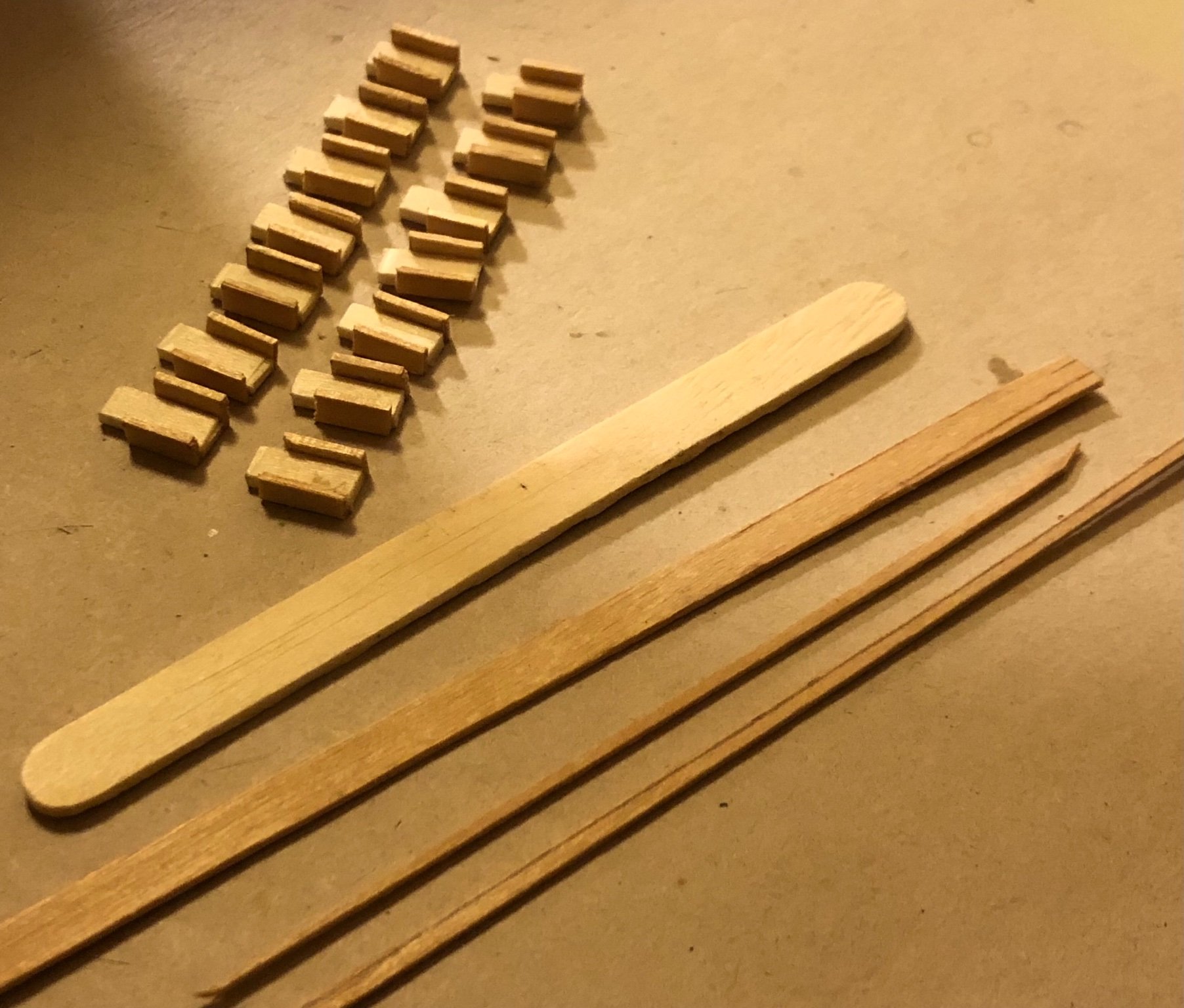
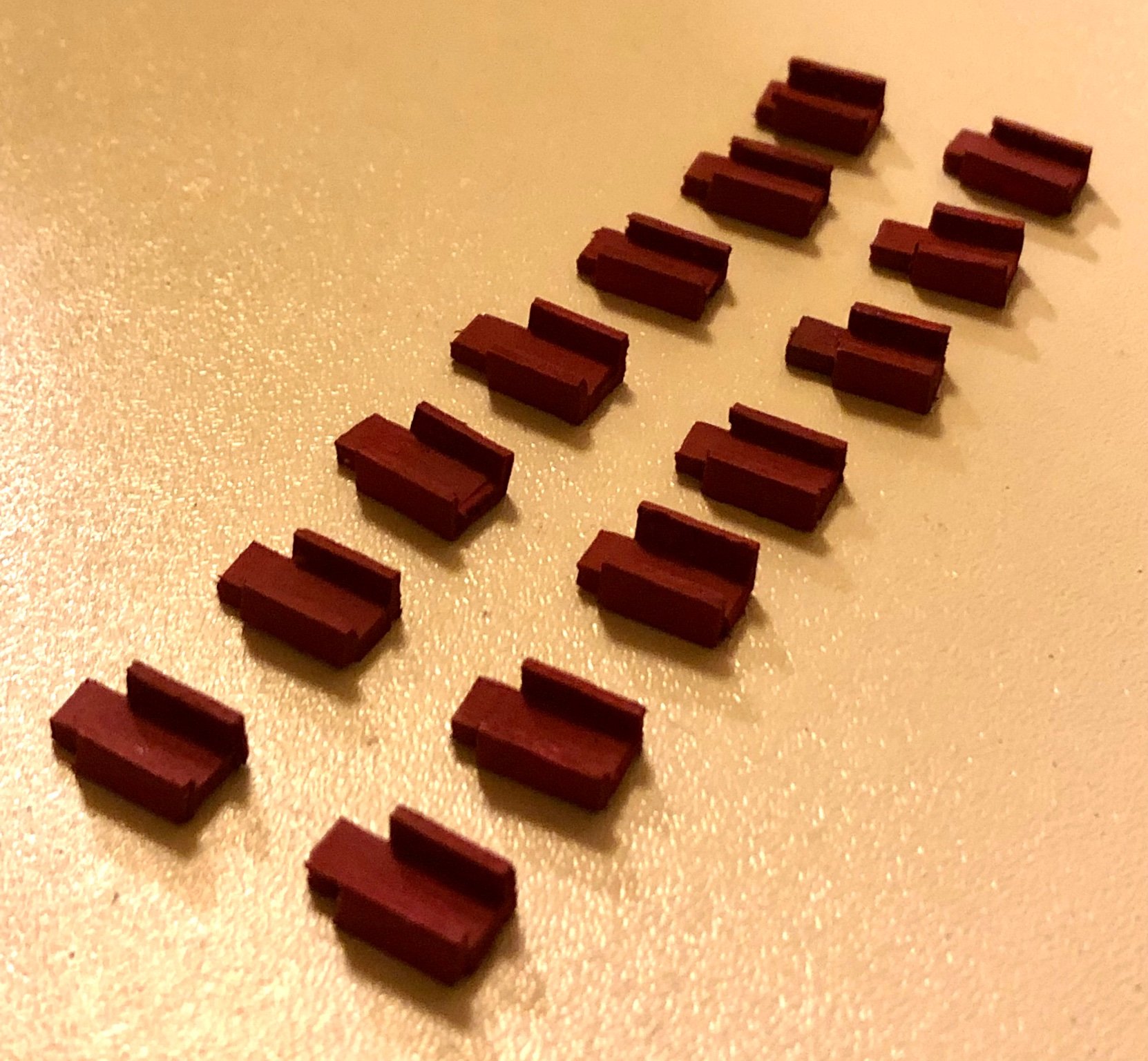
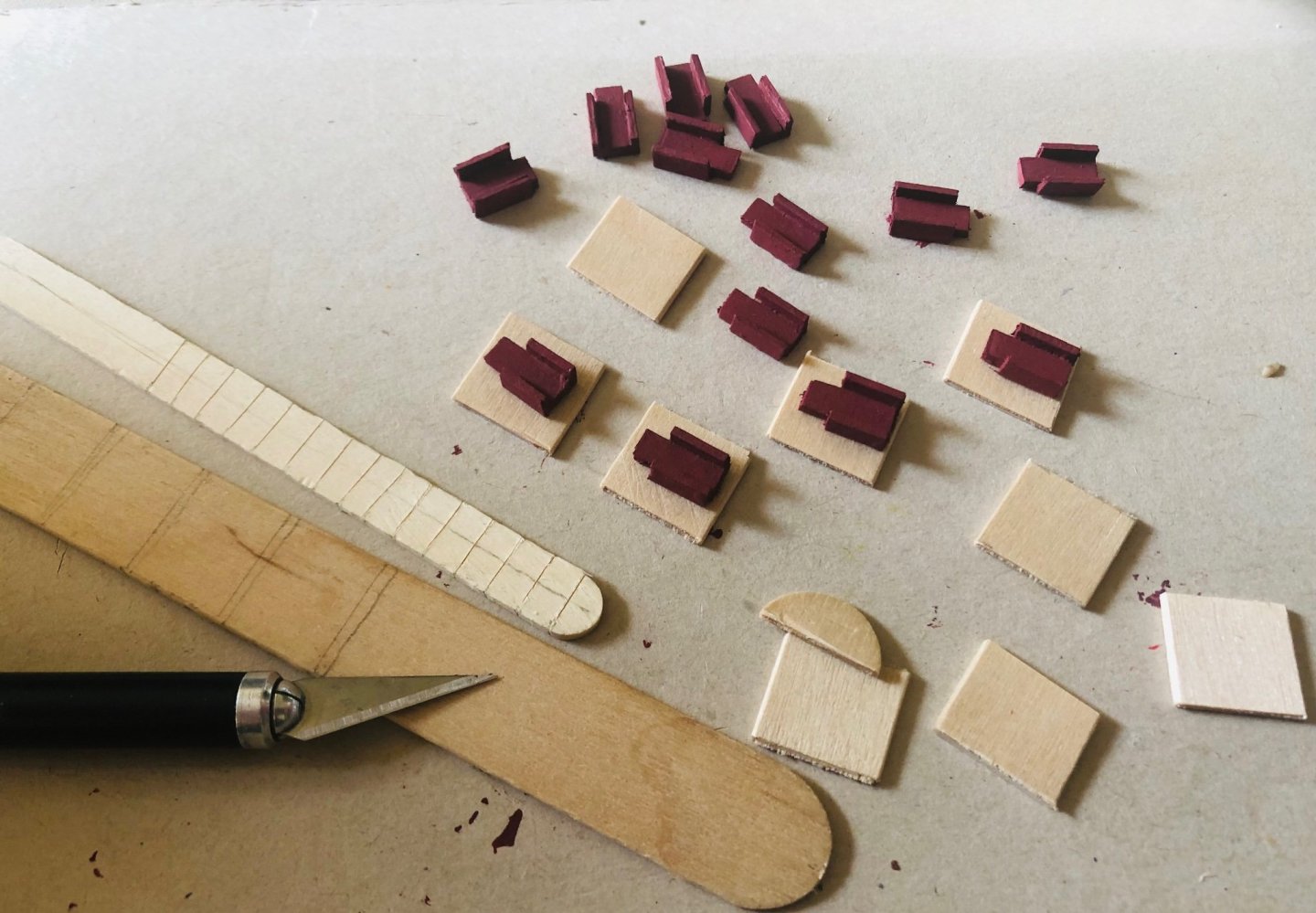
Completed cutting out the gun ports. Made the generic shape gun carriages from a craft stick and two coffee stirrers. Going to paint those carriages with hull bulk red (I can’t find information as to what color the Spanish galleon gun carriage are normally painted with. My gut feeling is they just varnishes them). Carriages painted. Looks ok. The trim off from the coffee stirrers will do nicely for making the deck grill later.


- 58 replies
-
- 4
-
-
- Spanish galleon
- Billing Boats
- (and 1 more)
-
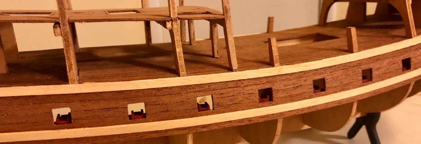
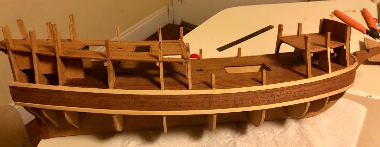
Installed the lower rubbing stake (wale). Starting to cut out the gun port by hand. Slow going cutting the thick single plank (not as easy to cut compared to double plank method). Marked the gun ports before cutting to save the cut out piece to use as the back side of the gun port (as gun port lid follows the curvature of the hull sharpe and is not flat/ straight shape).
- 58 replies
-
- 4
-
-
- Spanish galleon
- Billing Boats
- (and 1 more)
-
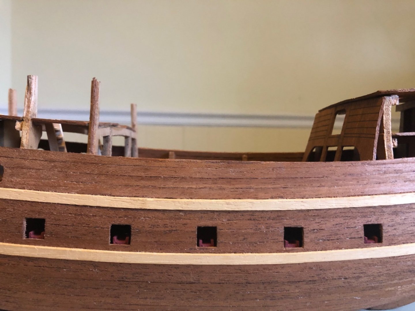
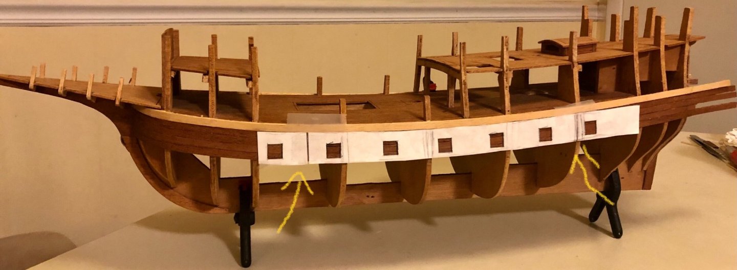
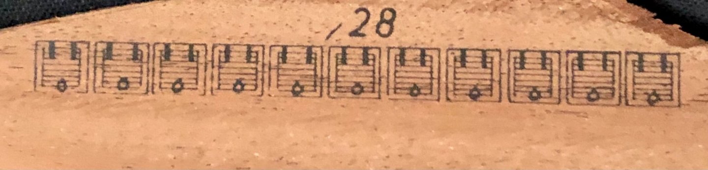
Single planking went a lot faster than I anticipated. Finished the 4 rows of planking under the first rubbing stake (wale) before the second rubbing stake is installed. Waiting for the 3 mm light color wood stake to get soft enough to work on. Trace out the gun port locations from the plan and made a paper template from it. I had to make an adjustment to the location of the first and last gun port as the plan side view can’t account for the additional length from to the hull curvature. I used the hull bulkhead as the preference, separated the paper template after the first gun port snd last gun port then taped the paper template back together (see arrows in the picture of the two gap spaces added). Taped the paper templates to the hull and Marked out the gun ports with pencil. The kit instruction indicated just to glue the printed gun port cut outs to the hull. I want to cut out the gun ports and install dummy half canons and opened gun port lids. Will start that once the second rubbing stakes are installed (it would provide support for cutting the gun ports).

- 58 replies
-
- 3
-
-
- Spanish galleon
- Billing Boats
- (and 1 more)
-
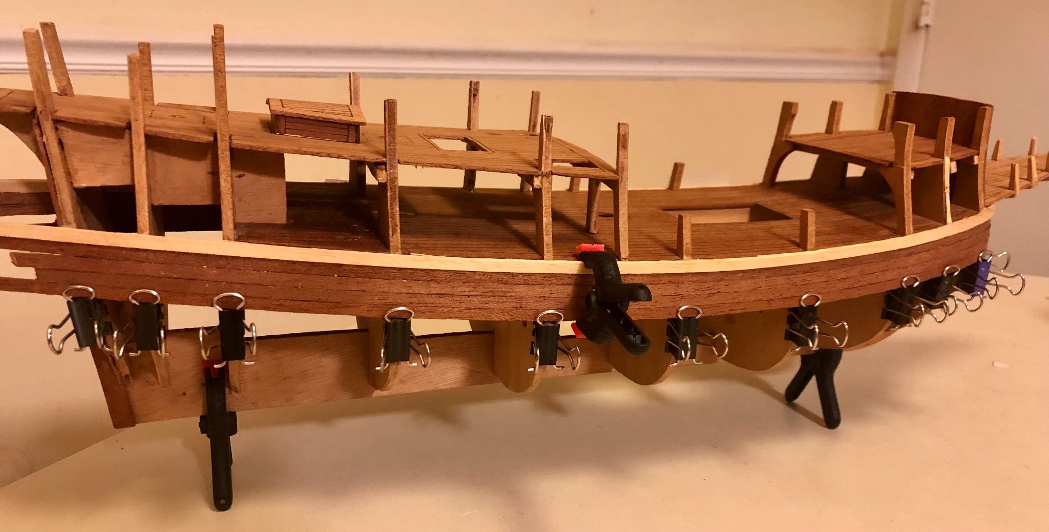
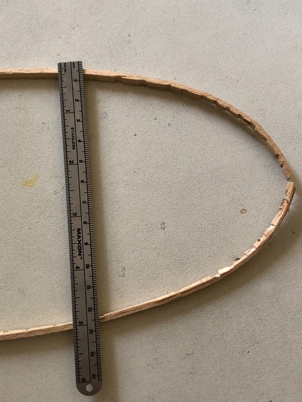
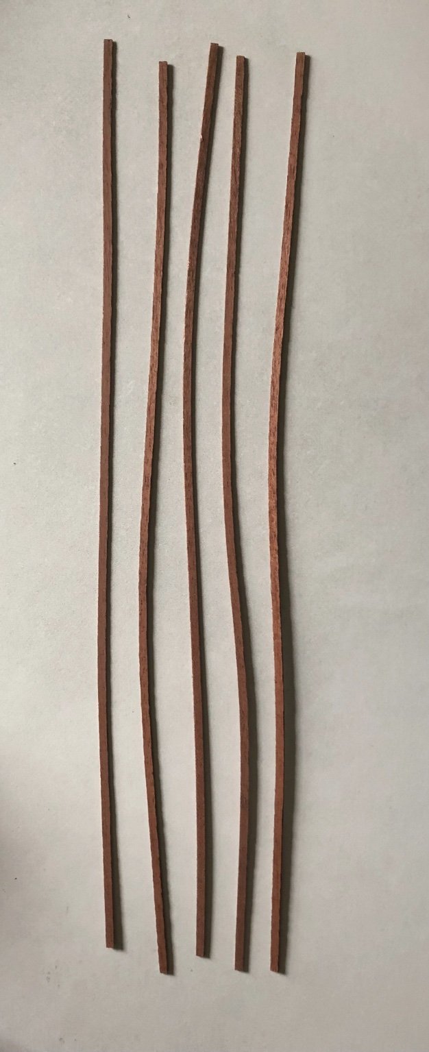
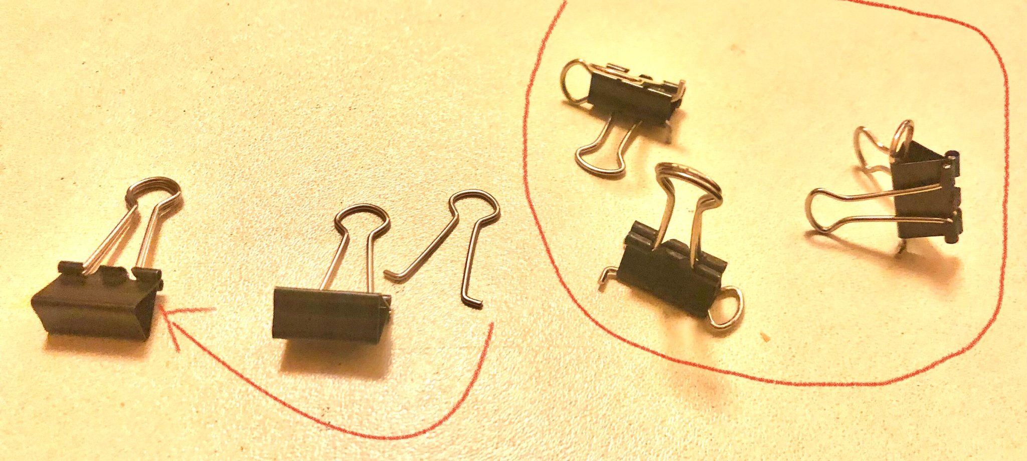
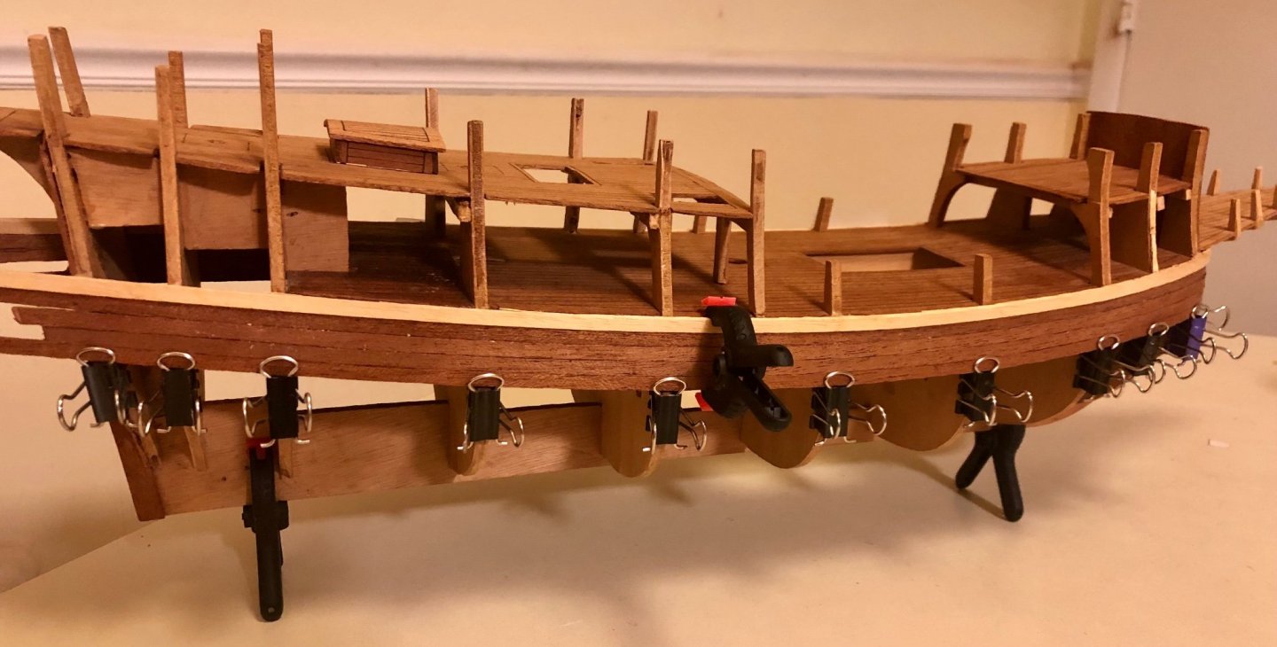
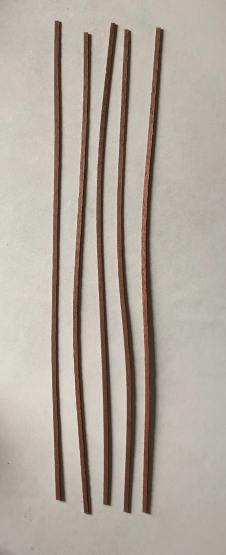
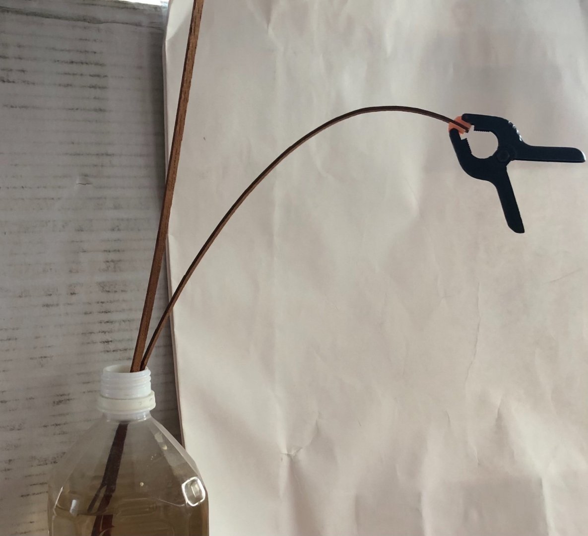
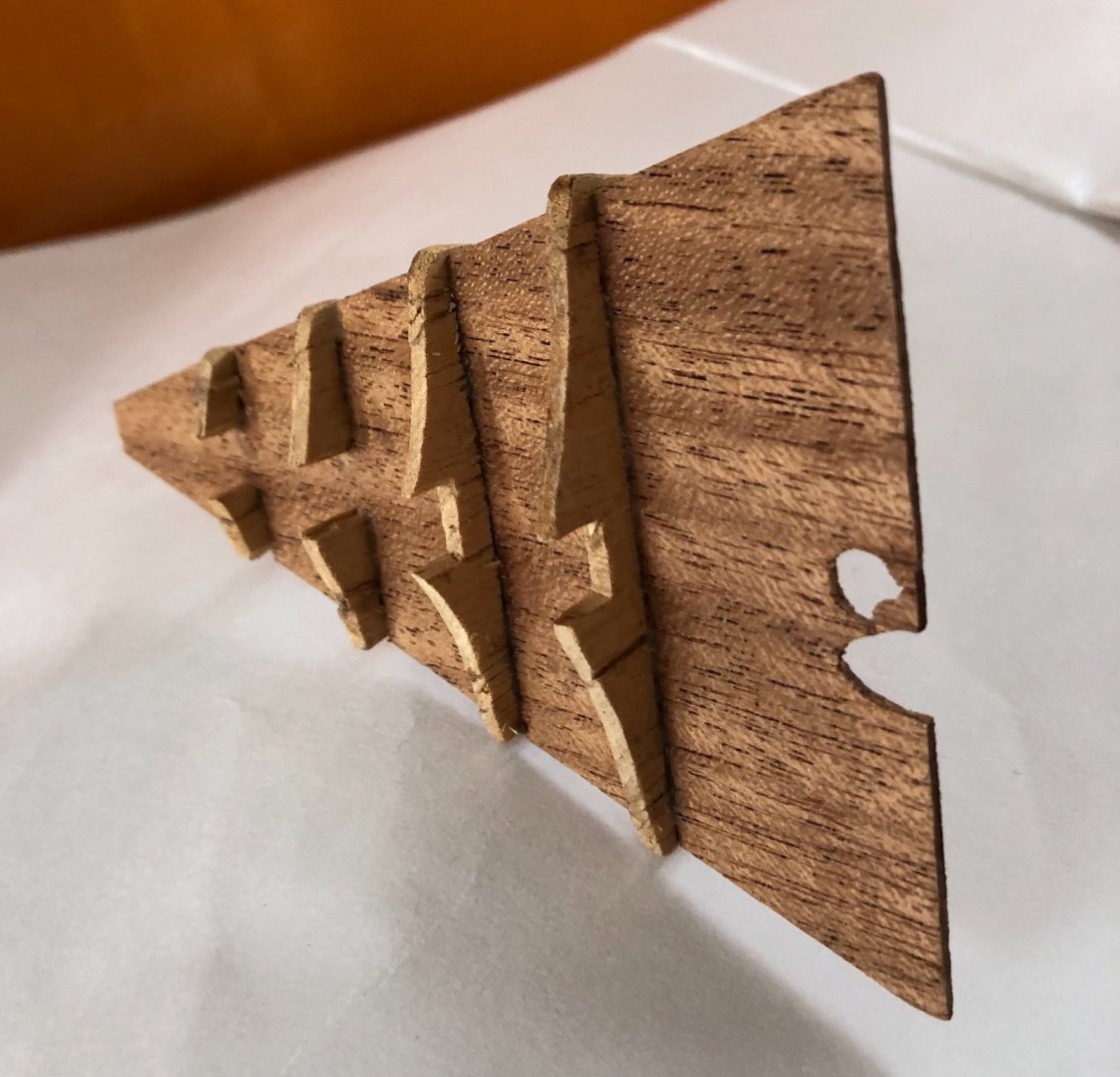
Took inventory of the planks in the kit. The light colored rubbing stake planks are 3mm thick and the mahogany hull planks are 2 mm thick. They are a challenge to deal with (double plank model strips are much easier to deal with at half or less the thickness). The 3mm planking turned out to be very difficult to work with. It doesn’t have any flexibility and break easily when pressure is applied. Tried soaking then bending, streaming and hot iron,, nothing seems to work. Ended up cutting notches in the plank then soak it over night, followed by fracture bending the plank. A Lot of the mahogany strips were wrapped from long term storage (only few are shown in the below picture). They looked really bad. However, it turn out some were easier to fit onto the hull’s curvature by default (go figure, who knew),,, The strips were soaked in water over night in a tall juice bottle with a clip on the end to “slowly bend it (deluxe bending naturale by gravity) - LoL. Final adjustment was done by cutting some small noches and fractured bending as needed. I used home made planking clamps made from folder clips (saw this hack on the internet years ago,I t works very well - no nail or hammering required) to hold the plank in place until the glue dries. To make a plank clamp (3 folder clips will yield 2 plank clamps) - (1) Remove the two wire handles from one of the folder clip. Take the removed wire handle and insert it sideway nto a pressed opened second file clip, then release the clip. you now have a finished plank clamp (easy peasy). The rfirst hull rubbing stake and first row of hull plank installed. Top view with rubbering stake installed on both side. It will take a bit of time to plank to the lower hull rubbing stake.......


- 58 replies
-
- 4
-
-
- Spanish galleon
- Billing Boats
- (and 1 more)
-
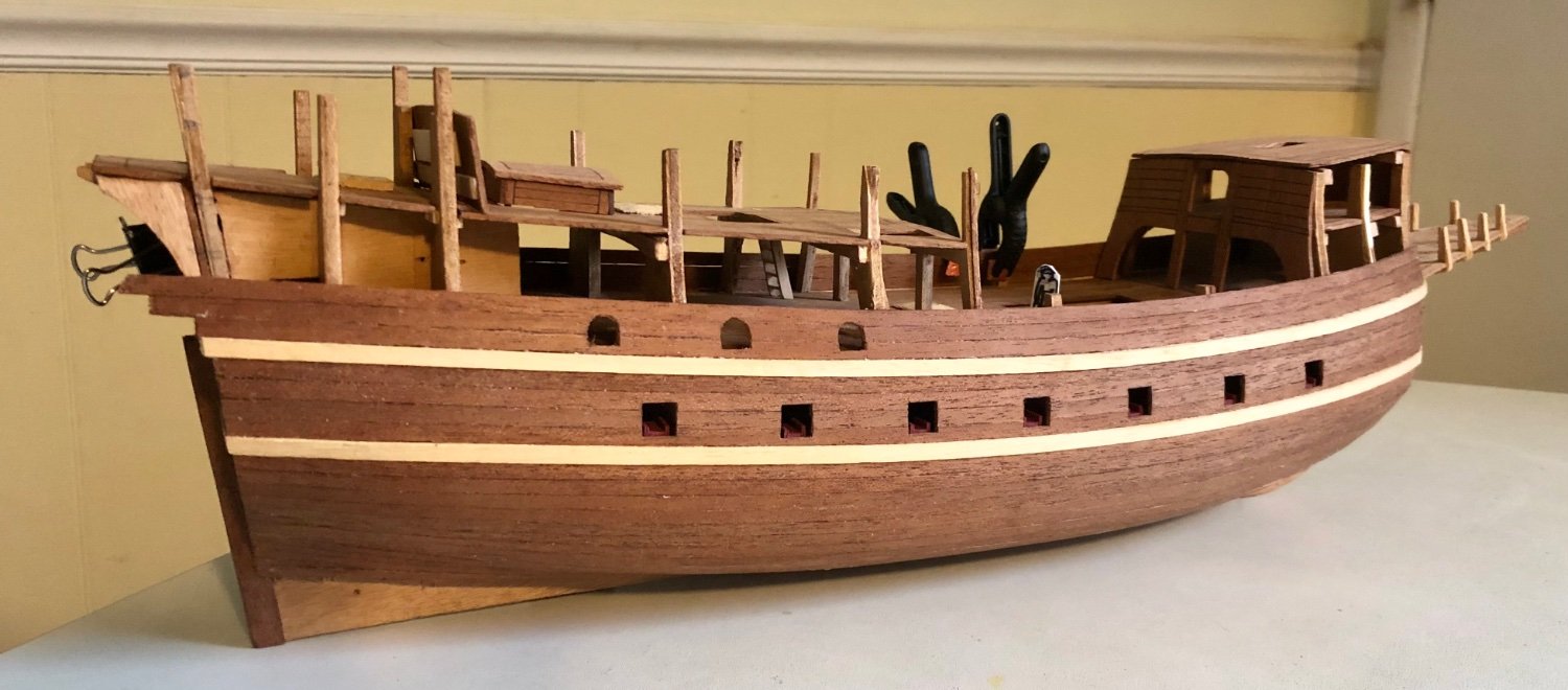
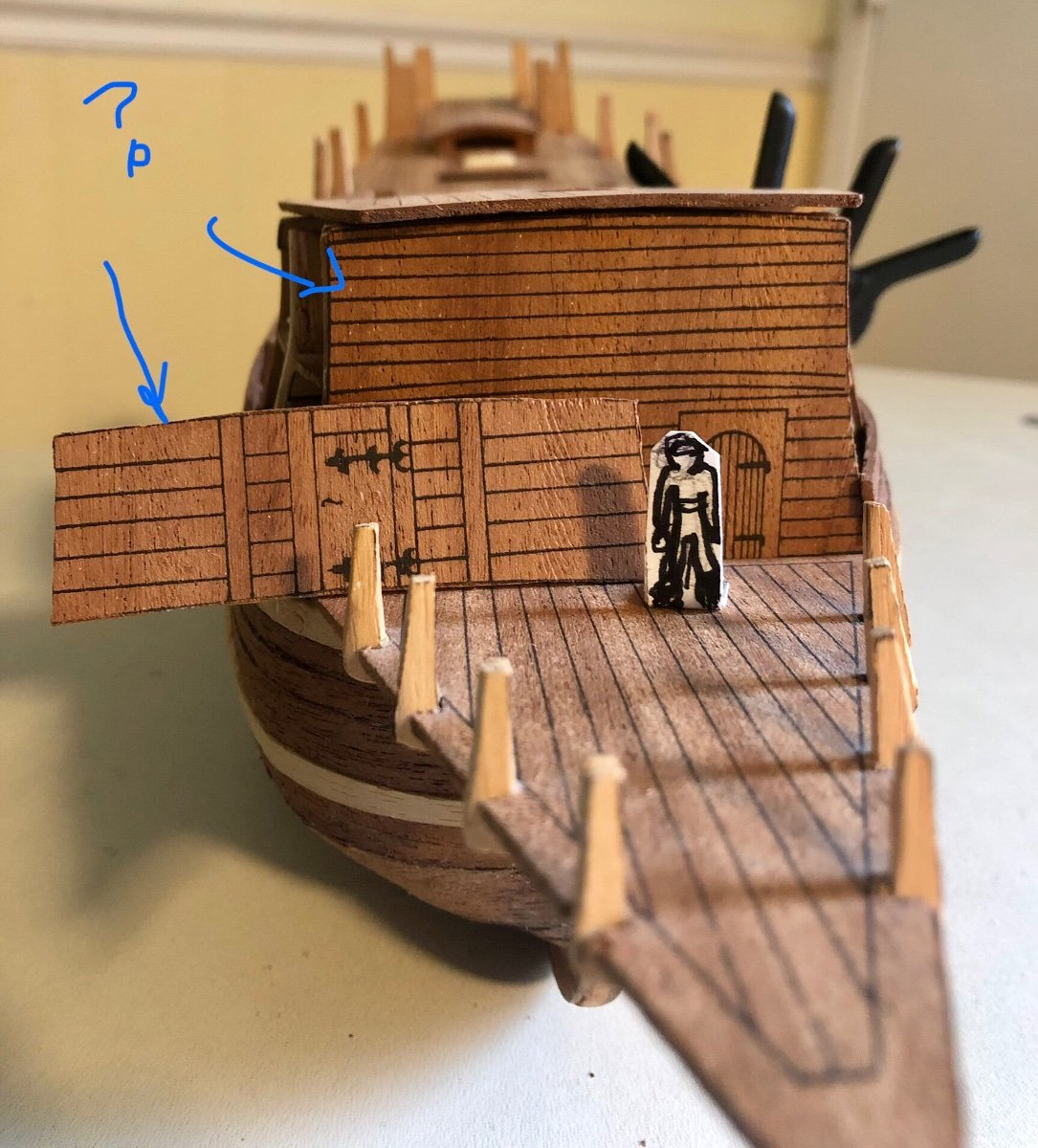
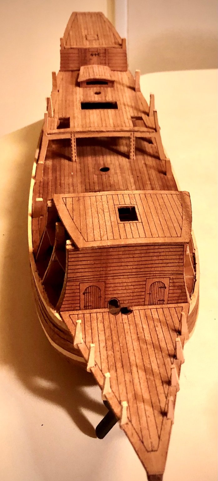
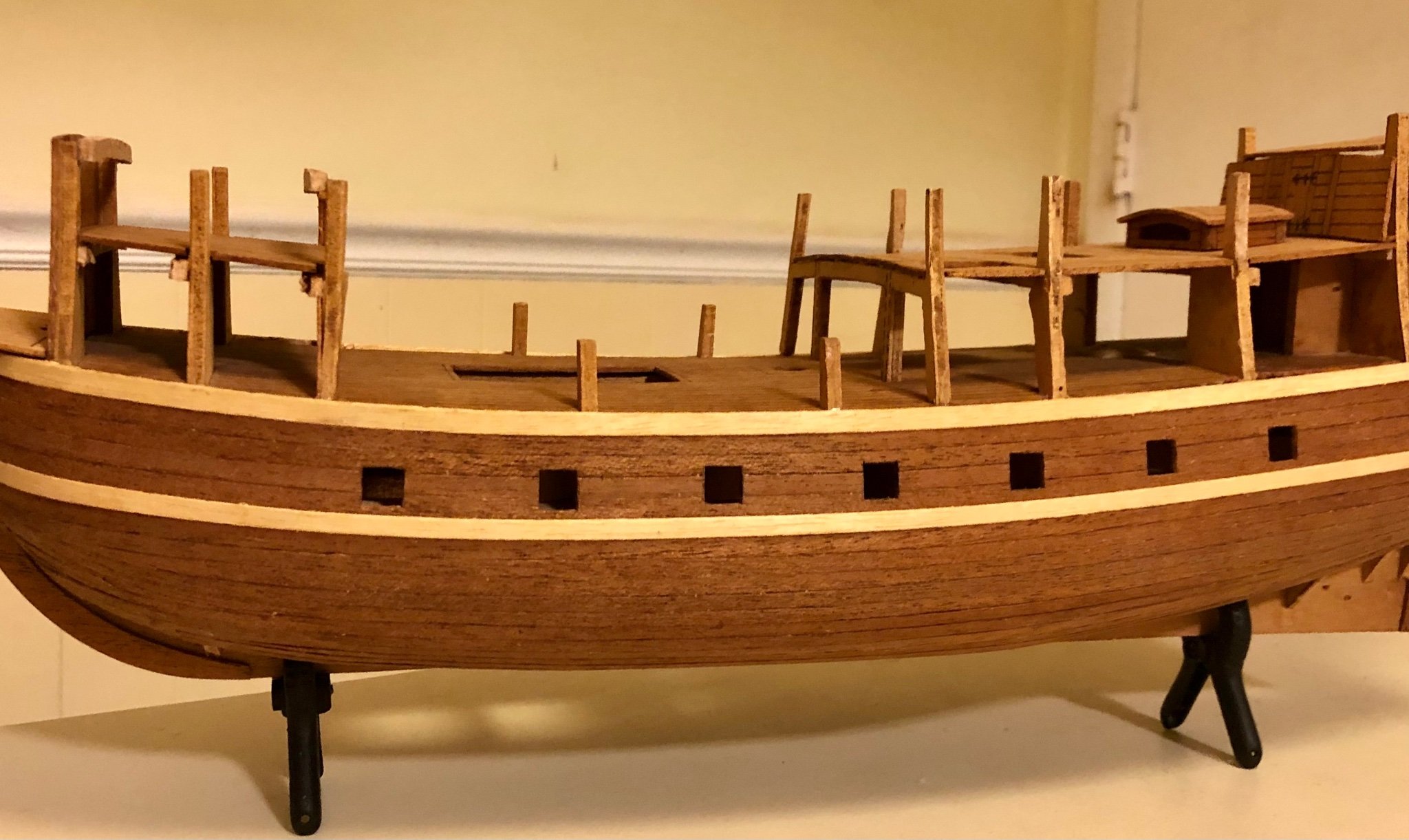
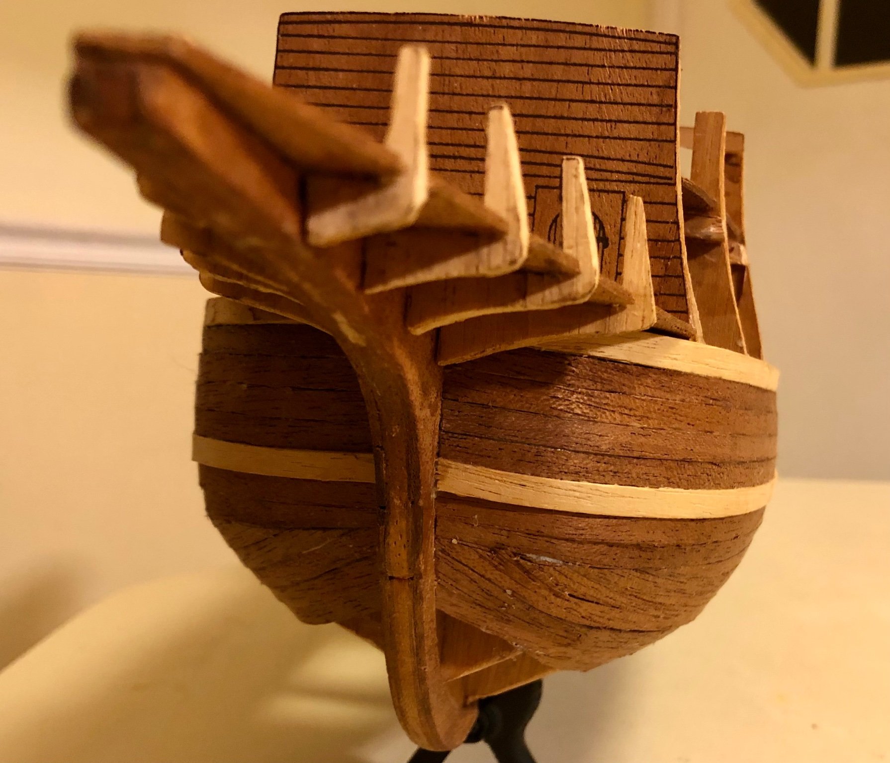
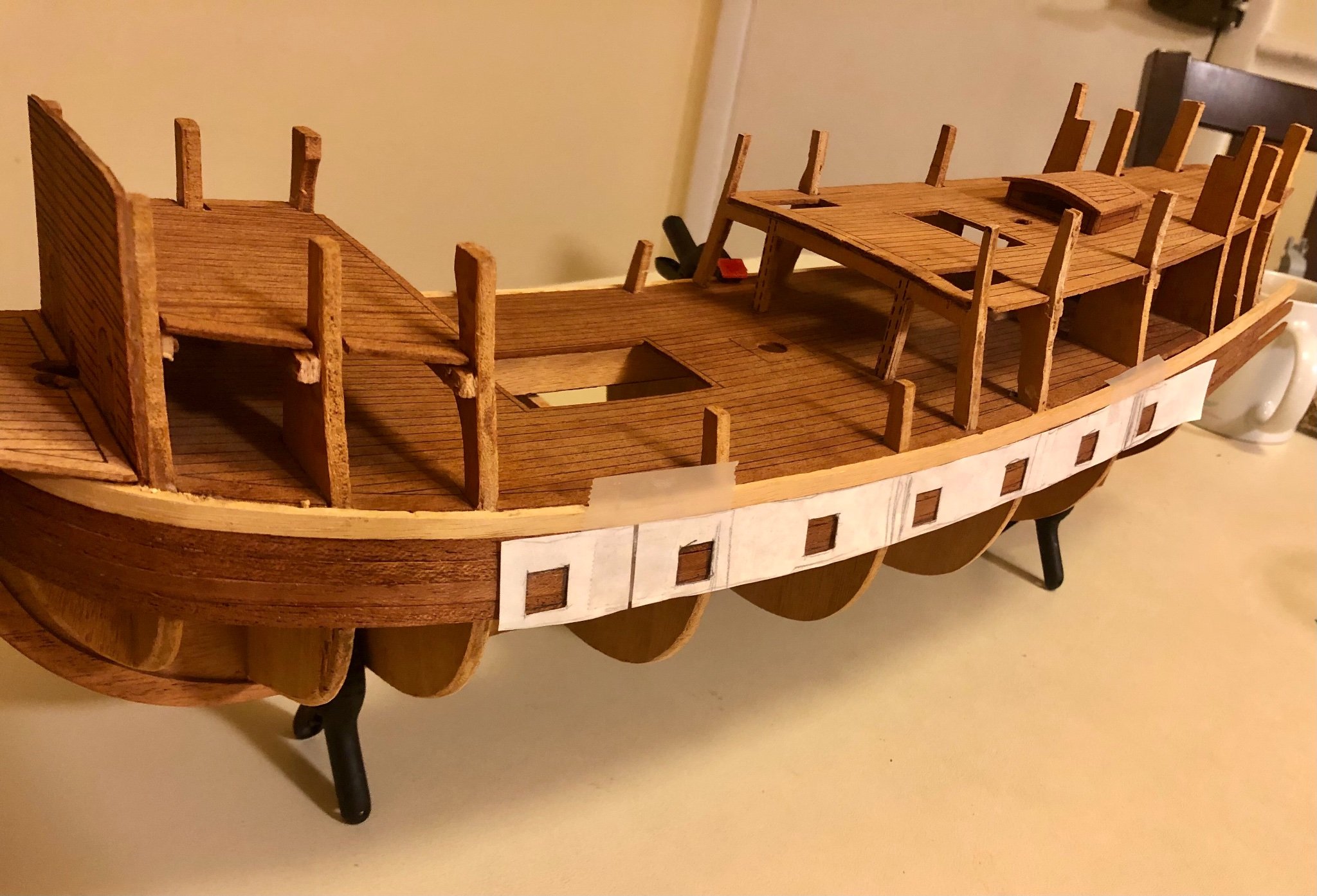
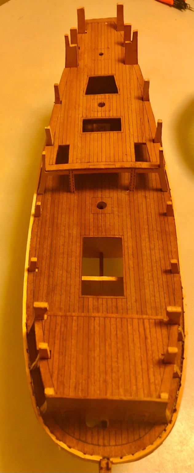
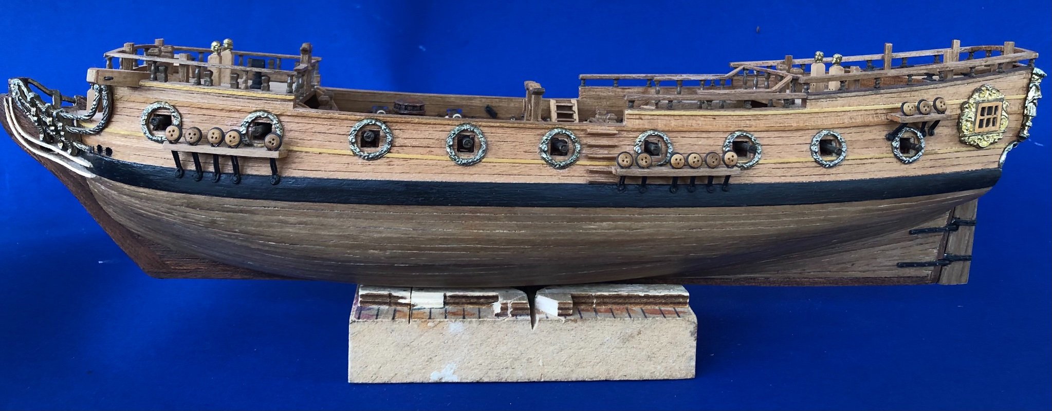
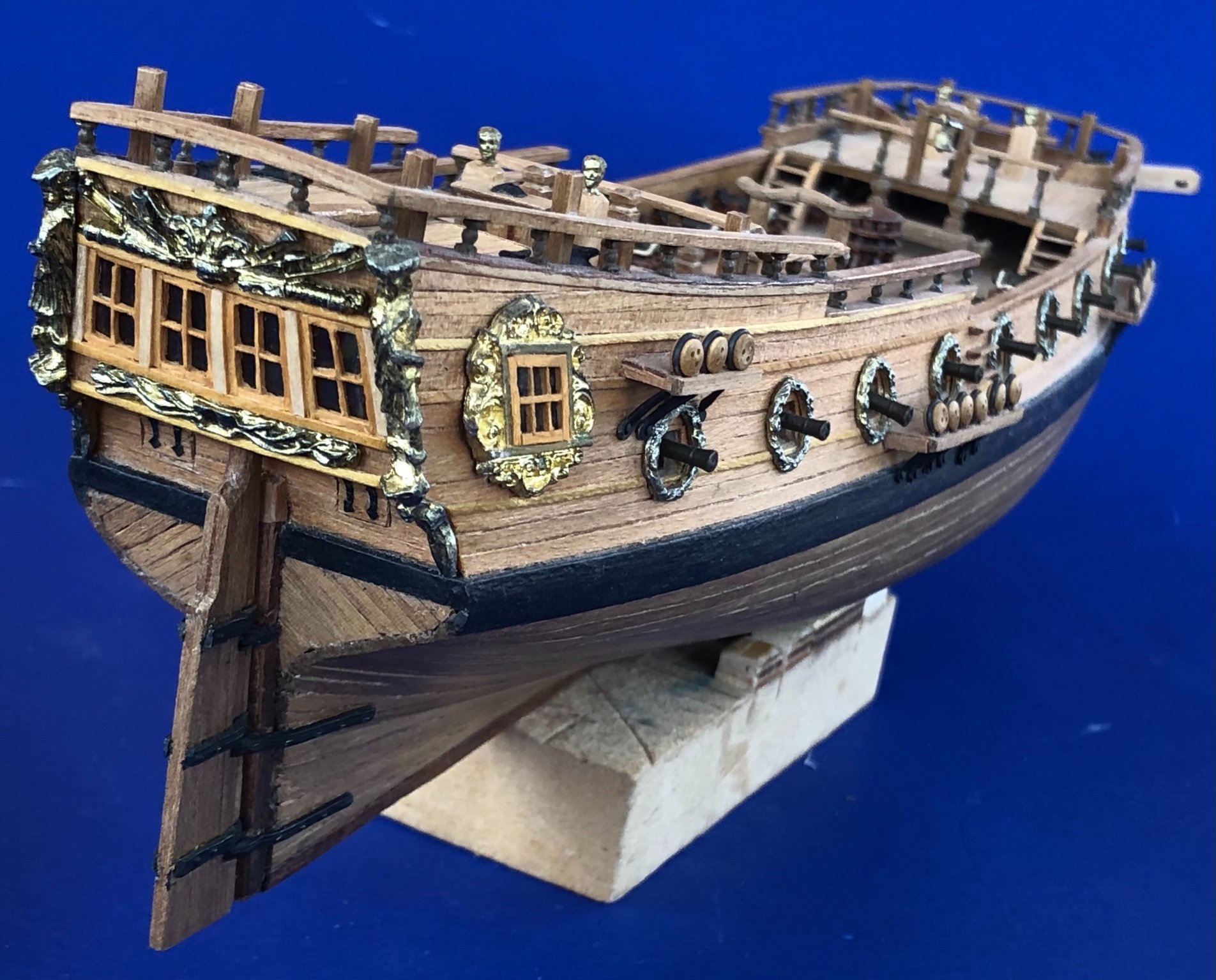
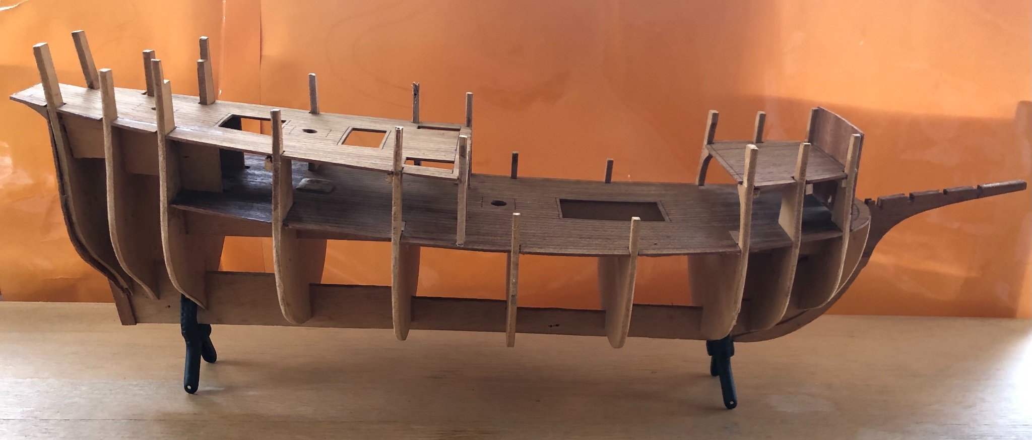
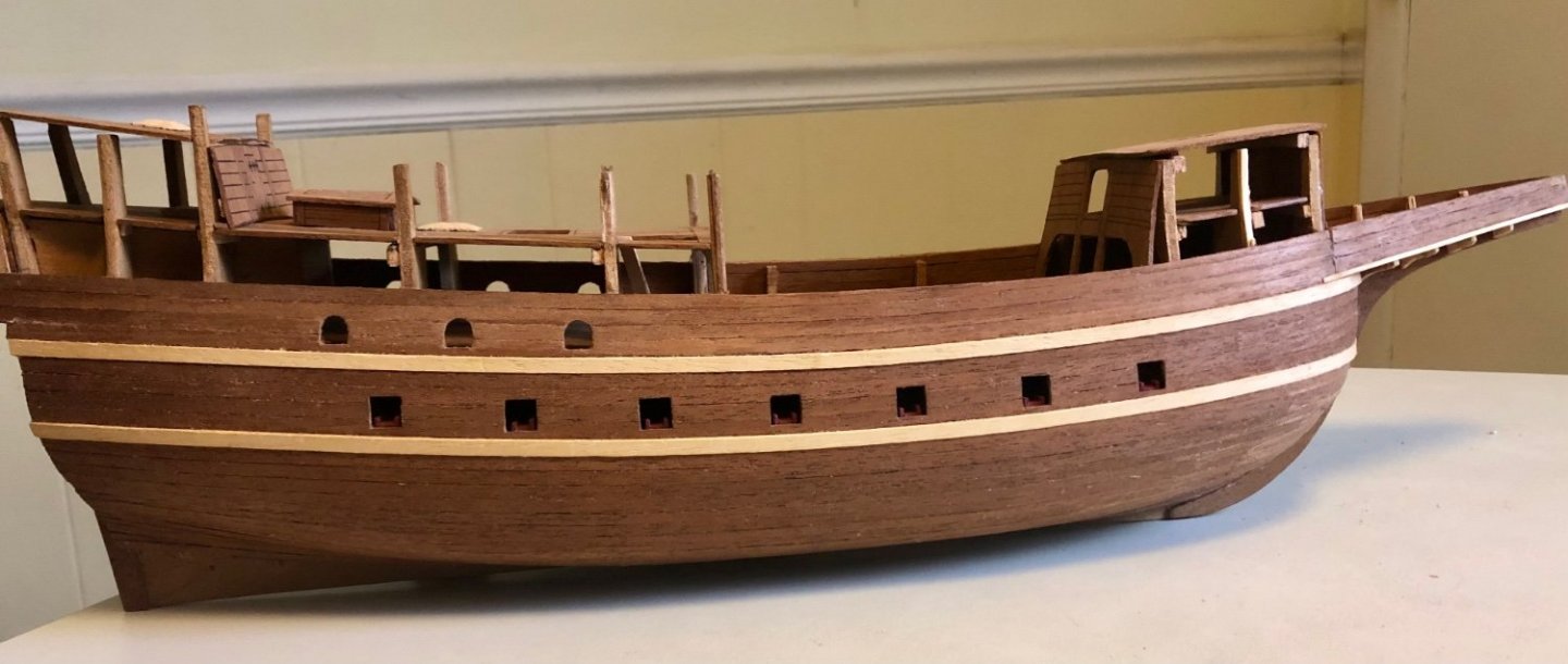
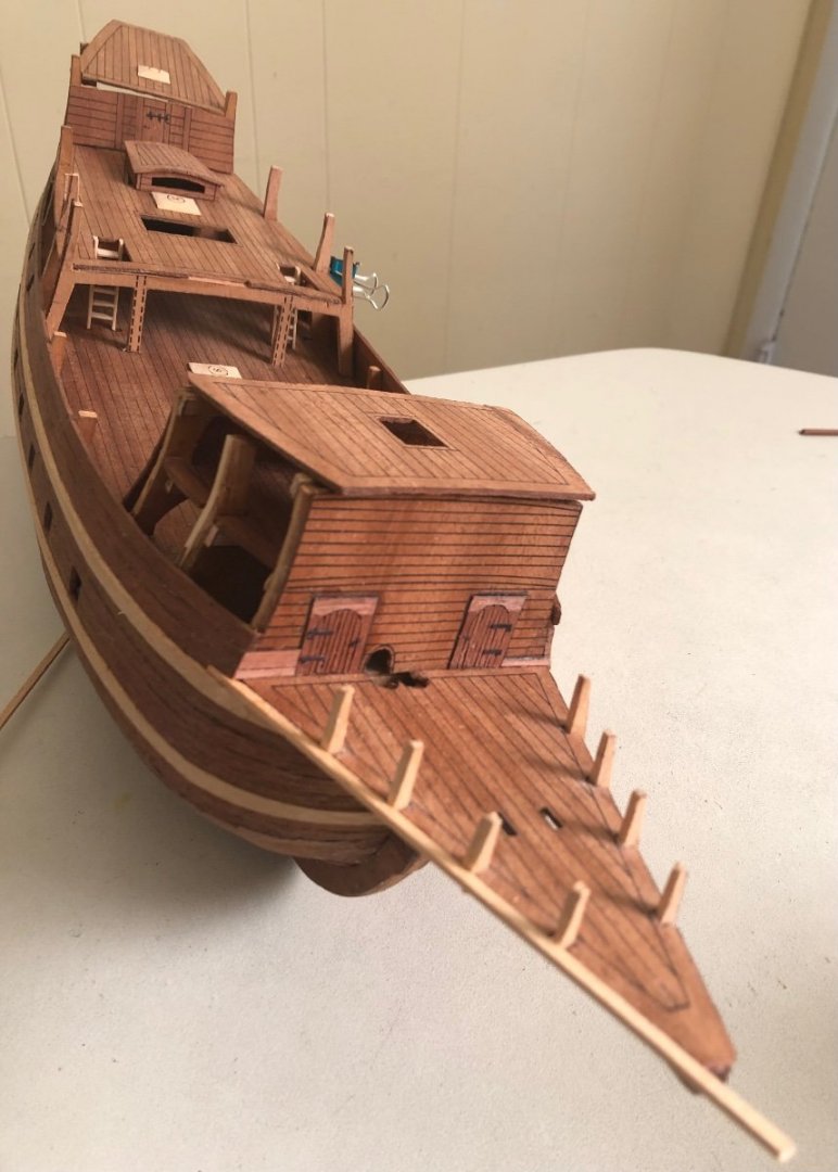
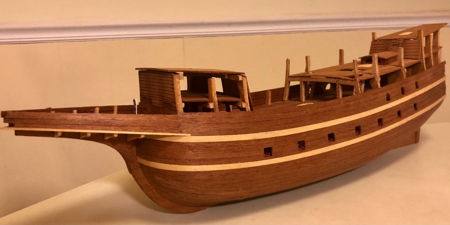
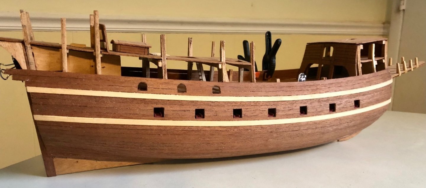
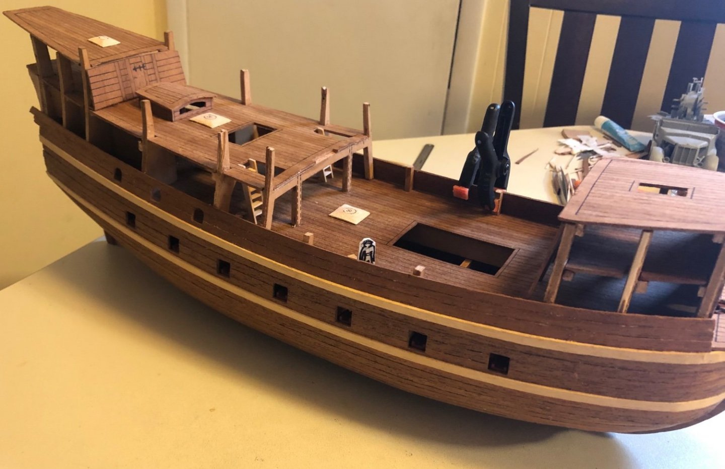
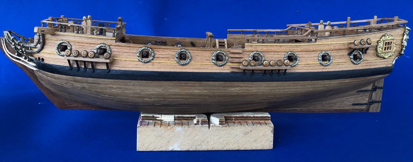
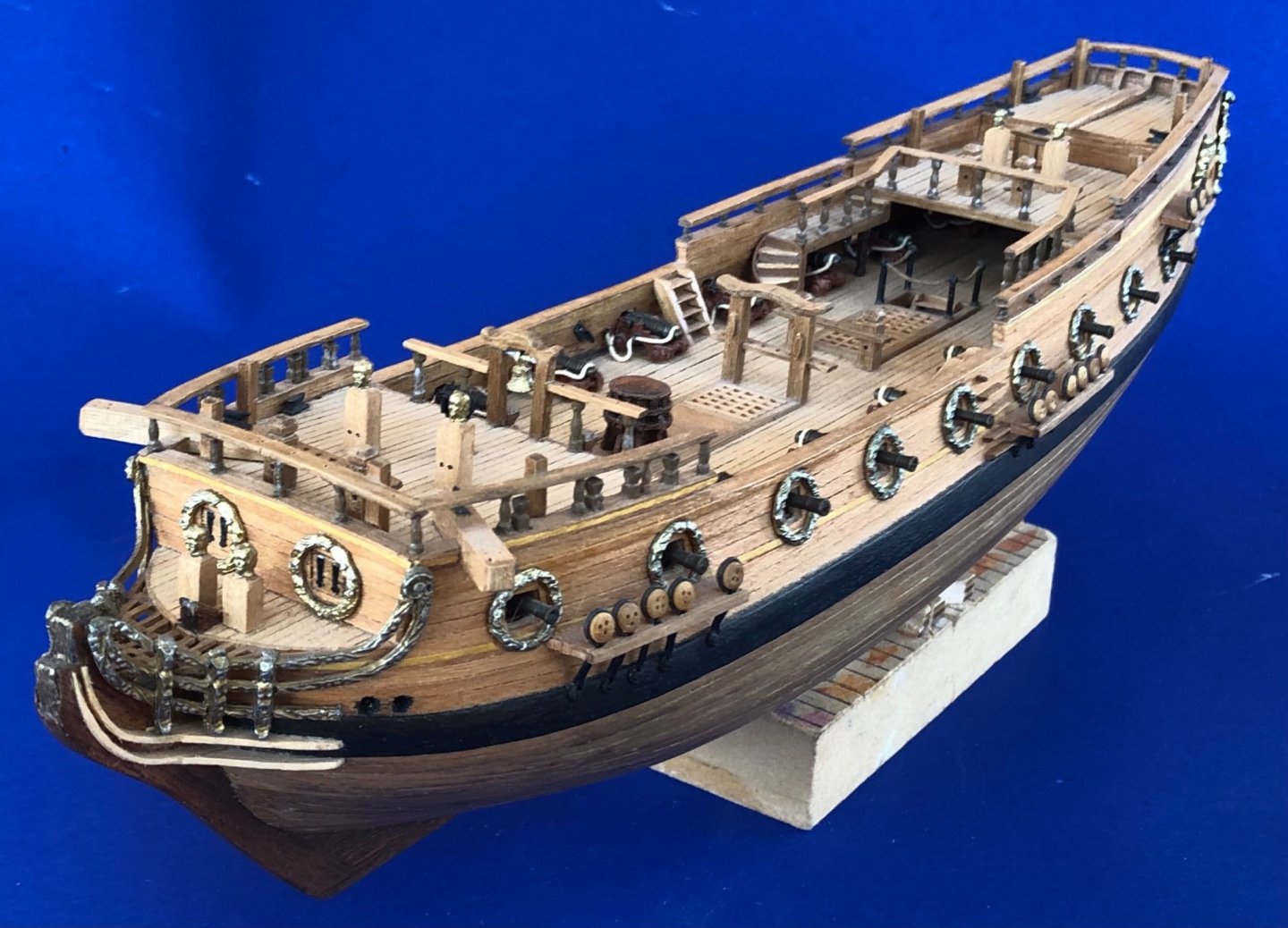
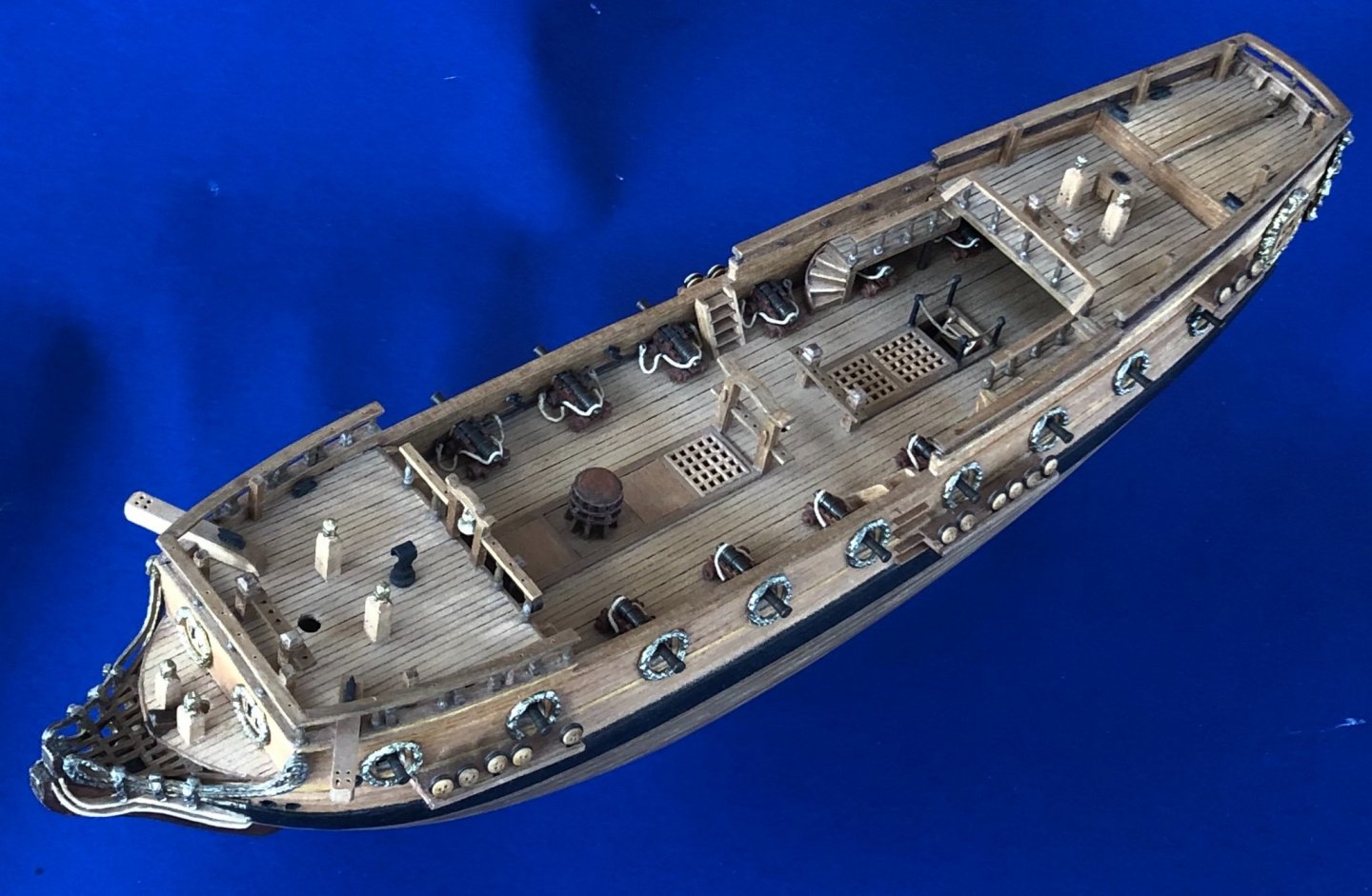
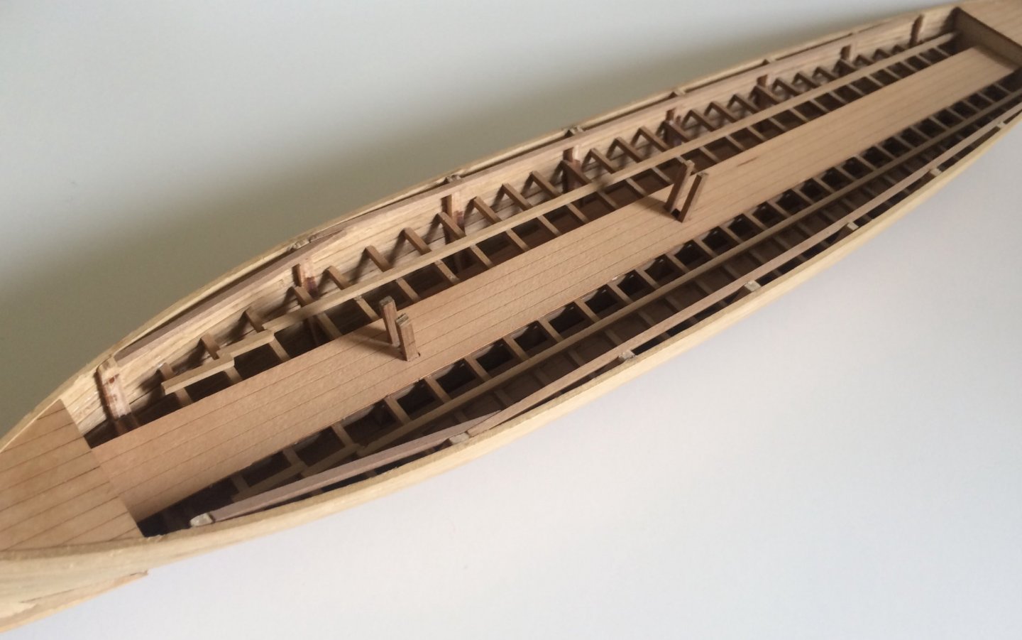
Thank you for your interest. Unfortunately I haven’t progress since I last posted. The ship is pretty much finished as an hull only model (minus the figure head, {which I need to carve from scratch}, belaying pins & the anchor addition). The good news is I will finish it as a fully masted and rigged model down the line. I uploaded some new pictures taken w iphone that has better resolution than what was available from 2014. Enjoy (if you like additional detail shots, let me know).

-
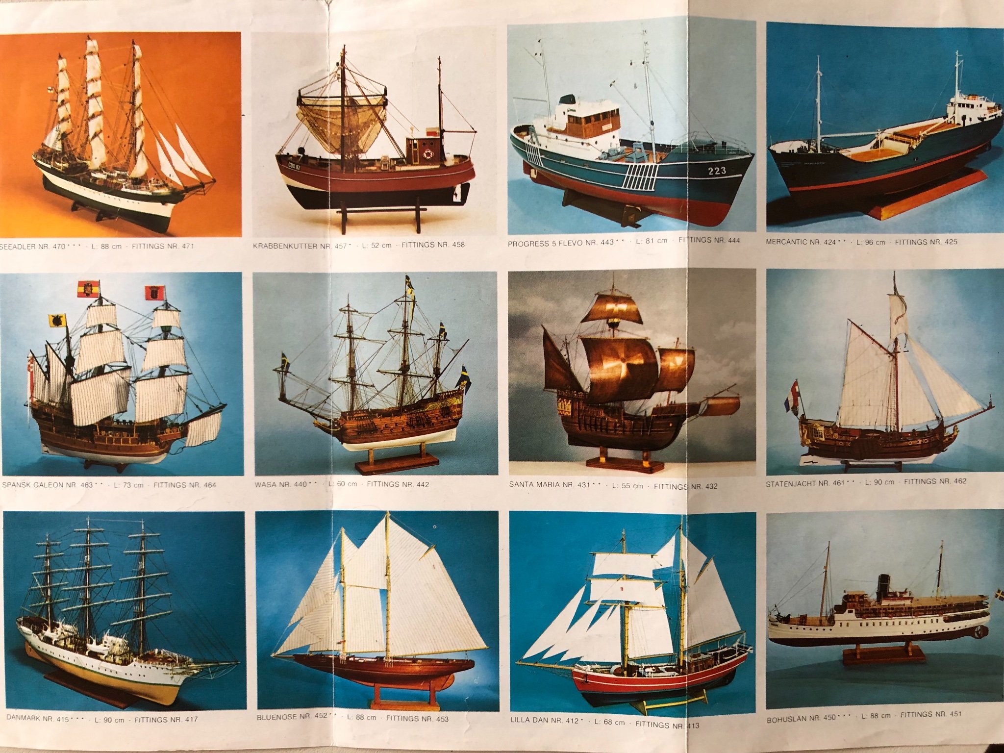
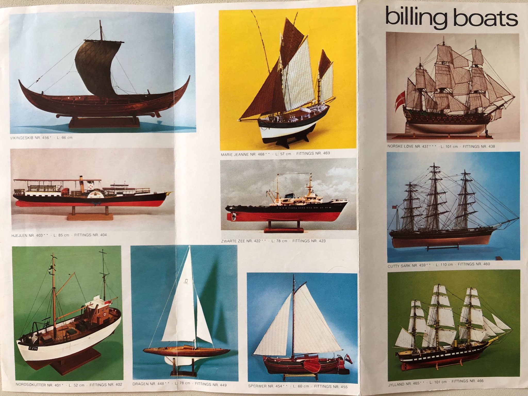
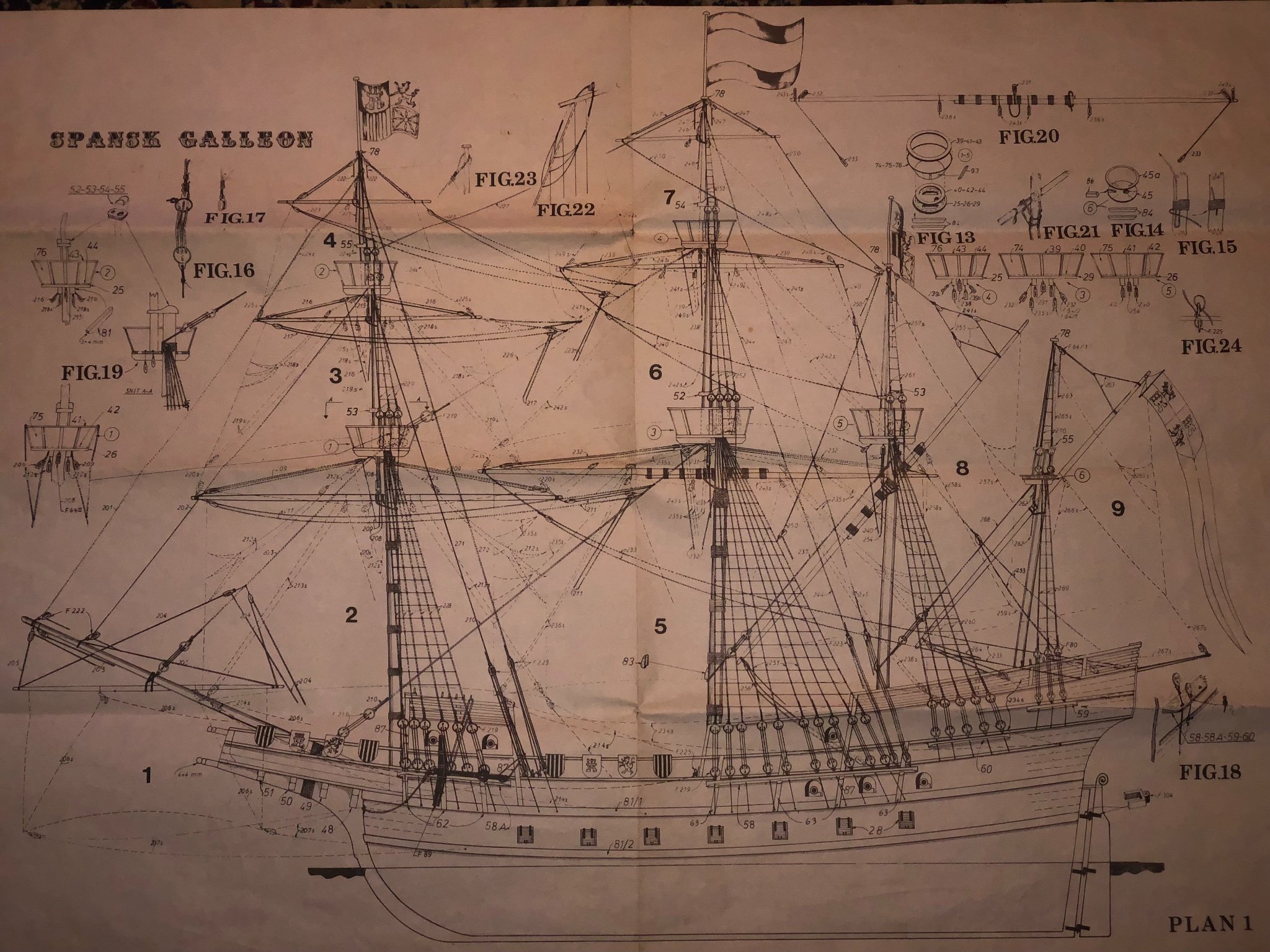
According to the instruction booklet, it is 1/66 scale (a bit odd, but close enough to the 1/64 scale norm). The Billing Boats catalog brochure that was with the kit indicated a length of 73 CM (a decent size). I photoed the other side of brochure just in case any one are interested with the available kits from Billing Boat from the time period (1960s ??)


- 58 replies
-
- 4
-
-
- Spanish galleon
- Billing Boats
- (and 1 more)
-
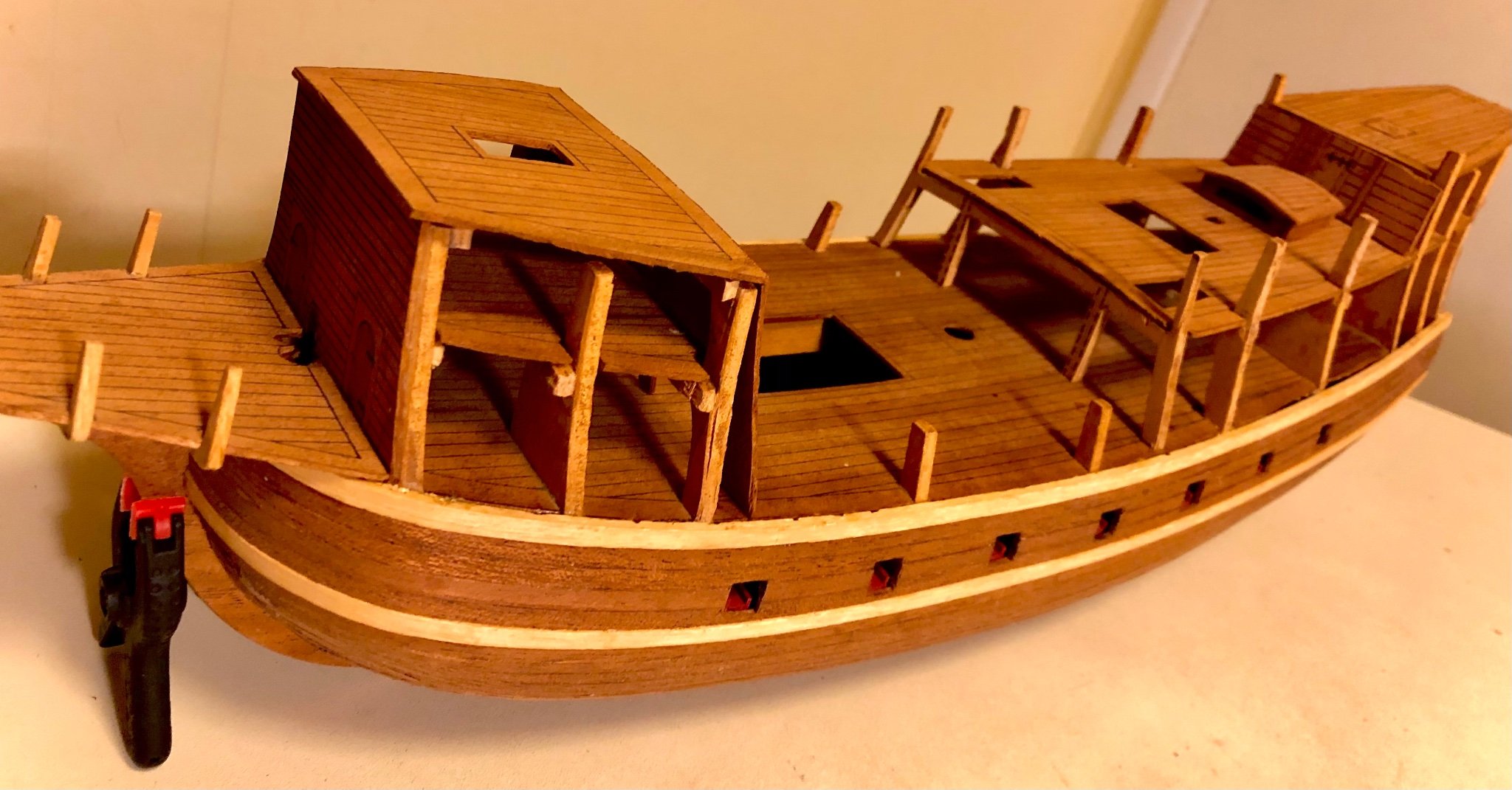
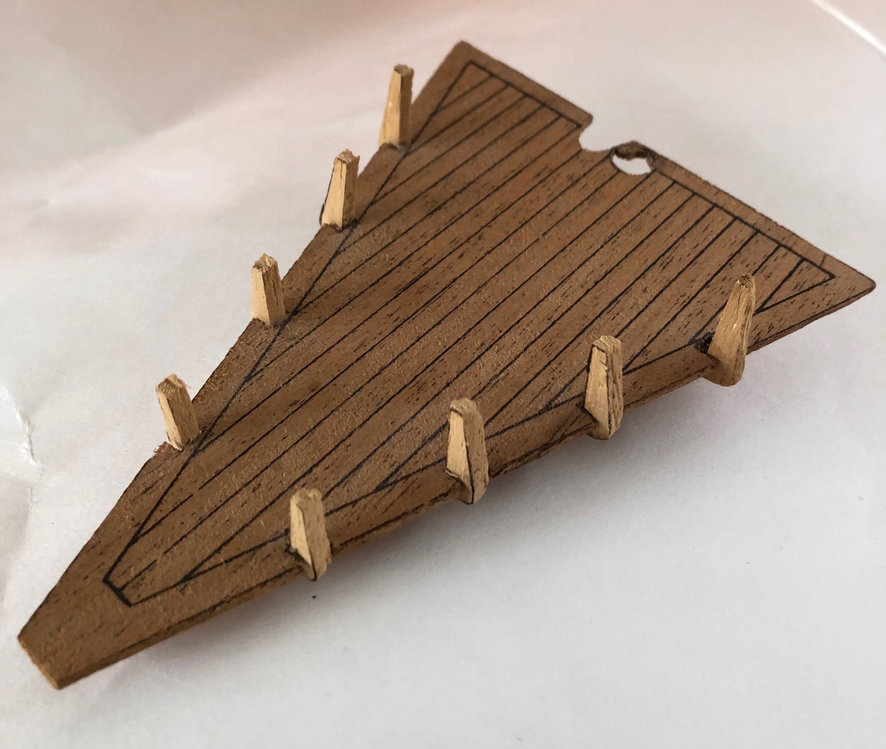
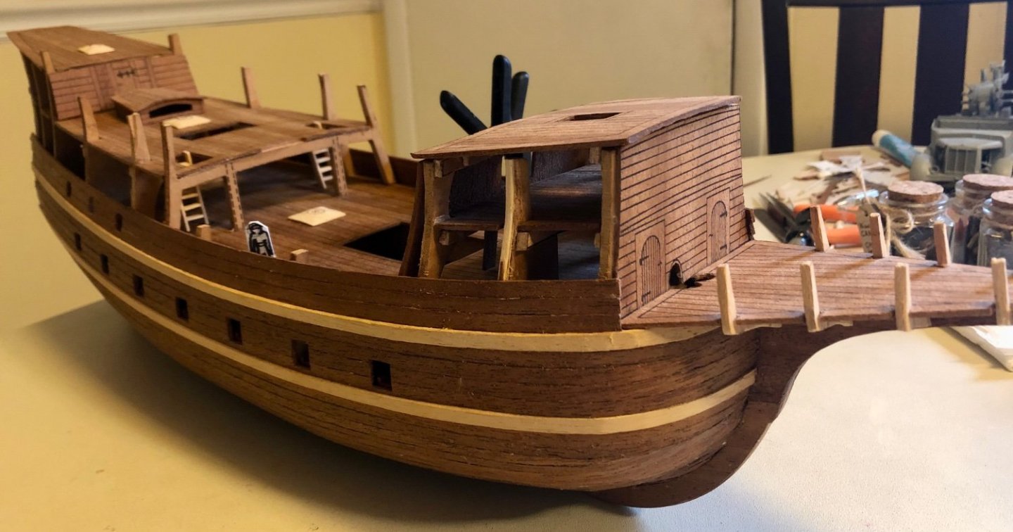
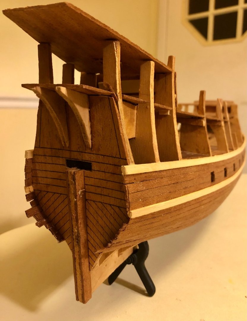
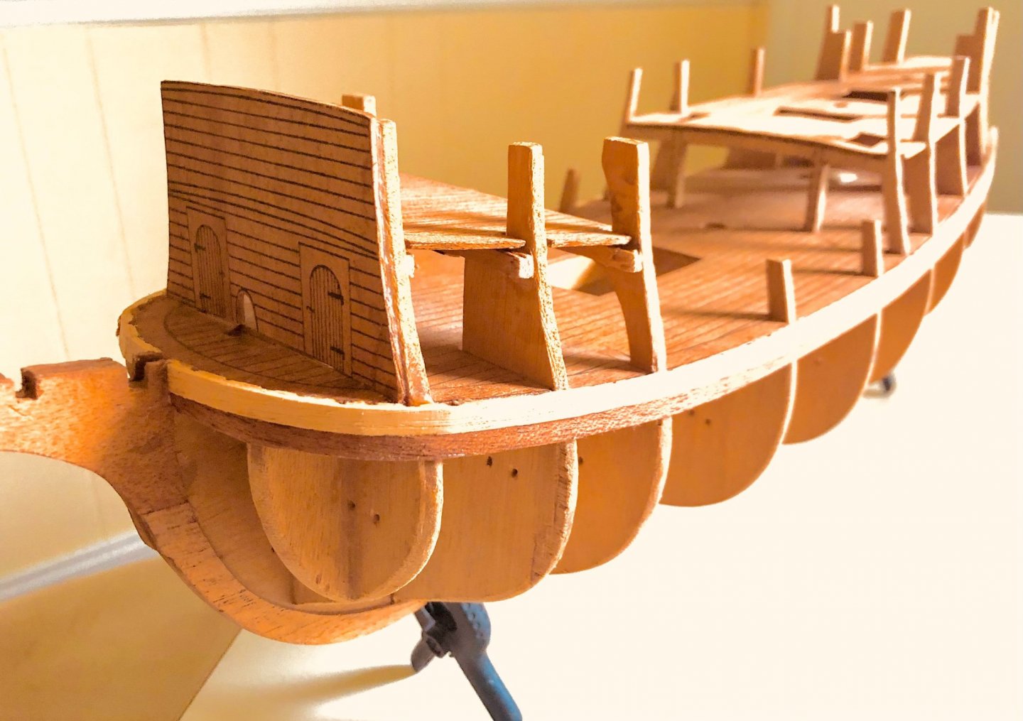
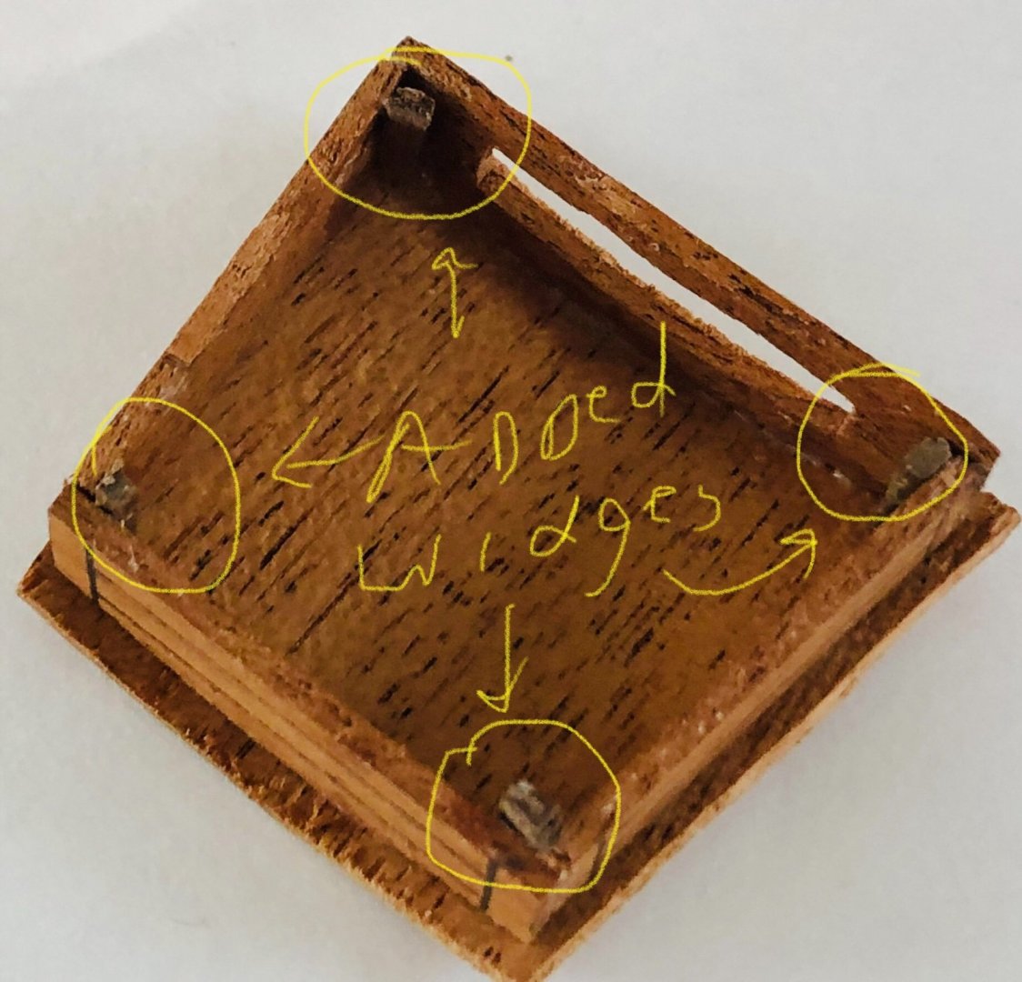
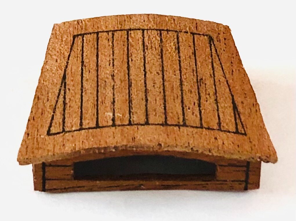
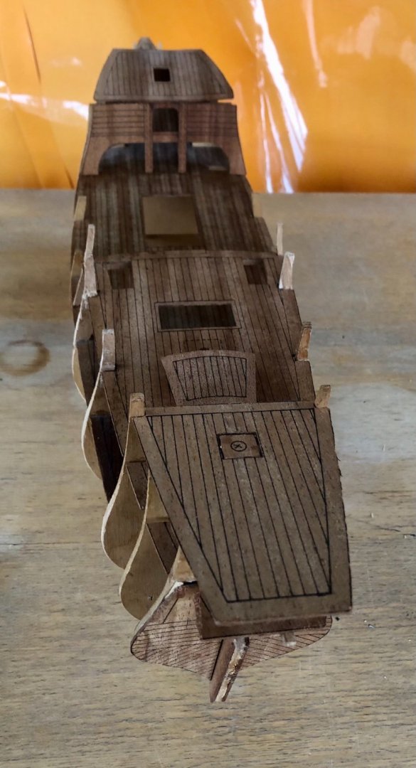
The head timber pieces outline were printed on a light wood board and needed to be cut out individually. Due to the characteristics of the wood, most either split or broke apart during the cutting. They were glued back together then attached to the printed head decking panel. Once attached, the head timbers became very rigid and stable. The helmman's shelter was made from 5 parts cut out from the printed boar. The roof panel required soaking in water overnight, then bend over a cup with rubber bands until dried and the shape is set. 4 wedges made from scrap wood were used to tie the 5 parts together. The wedges are also cut a bit longer than the shelter height. They will server as anchor /alignement pins into the deck opening. Cut out the back side of the forecastle & top deck and the poop deck. Dry fit those to get an idea on how they well they fit. The last hull bulkhead is too high compared to the other two bulkheads in front of it. This need to be cut down in alignment to the others in order for the poop deck to sit properly.


- 58 replies
-
- 6
-
-
- Spanish galleon
- Billing Boats
- (and 1 more)
-
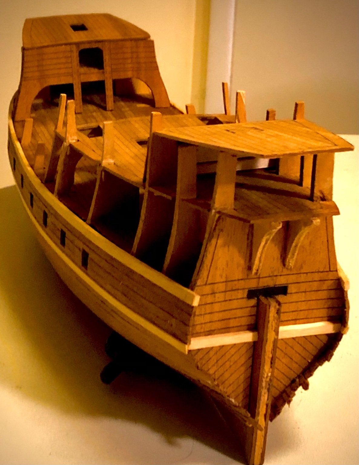
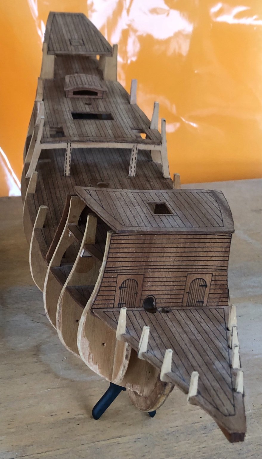
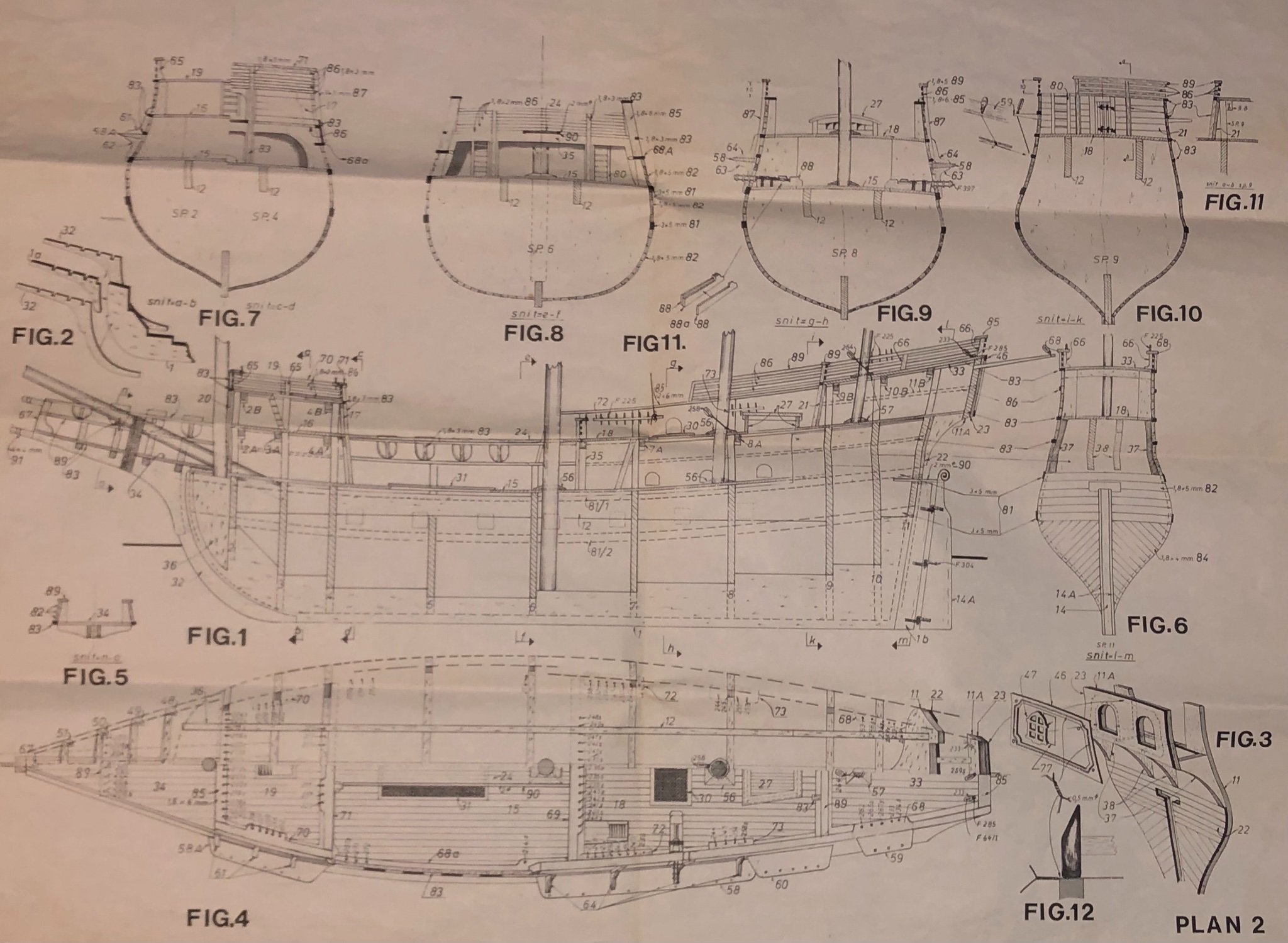
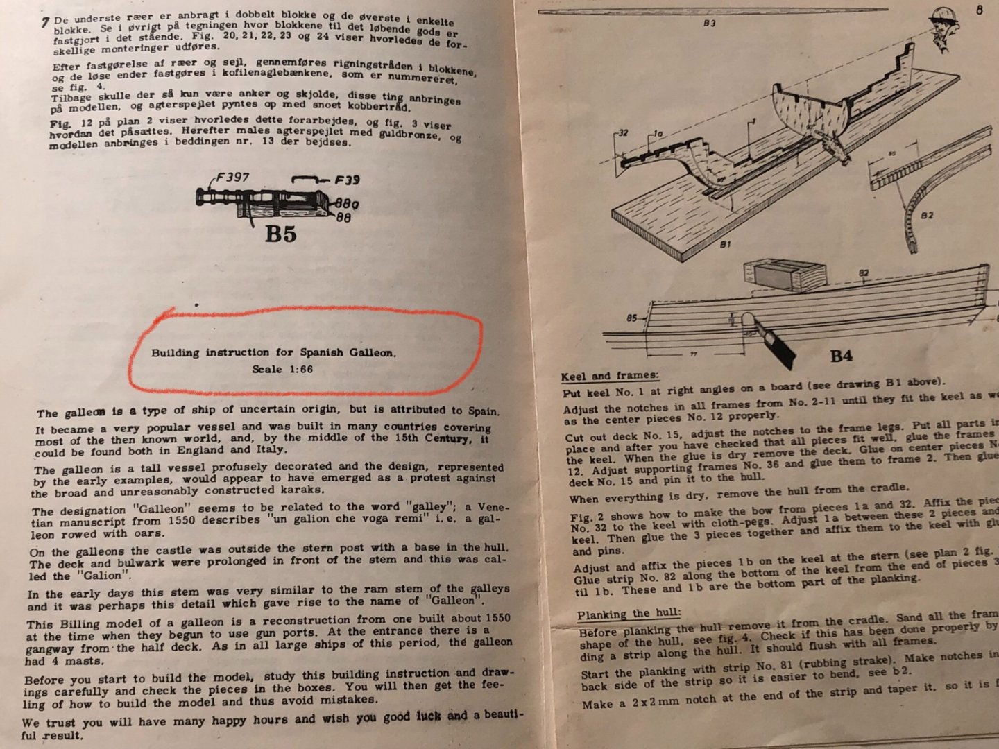
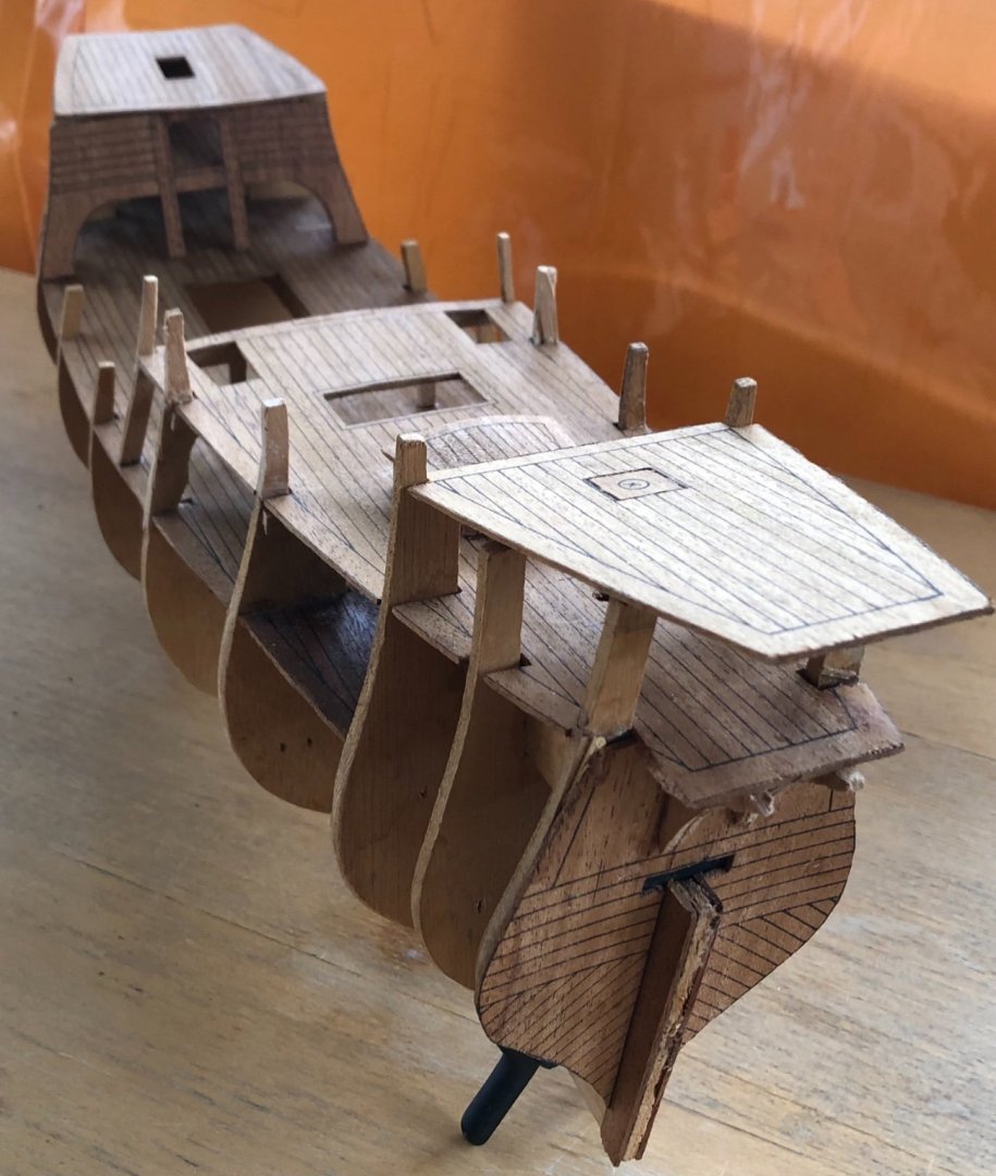
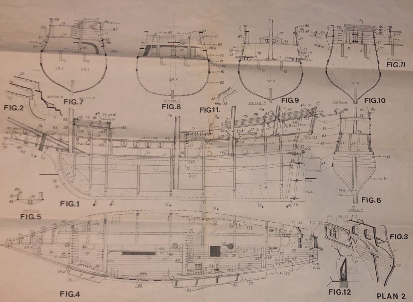
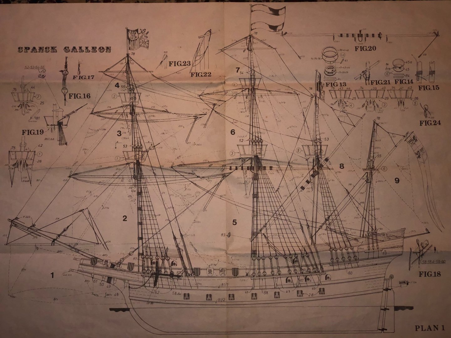
I got this kit on Ebay years ago. It was started and abandoned (i believe due some of the hull bulkheads upper deck pieces were broken/ missing). The model’s bulk heads, main deck and front side of the fore castle and the stern panel were put together. since this Billing Boats kit was manufactured in the 1960s (i think), i figure i better do something about it before it disintegrates into dust. The only build log /youtube video I can find about this kid is the one by Frankie Day. The kit doesn’t have the details of modern kit standard, however, it does have a beautiful hull lines, 4 masts and plank walkway between the forecastle and the quarter deck, which are rare subject matter combination. Can’t find much history or details about the kit or the ship it supposedly reepresents. It looks like it is just a generic representation of a Spanish galleon of the period. I plan to build the model as close to the kit enclosed building drawings (two draon one sheet) as possible. Drawing 2 provides impressive number of details/clues. The kit only provide printed gun port lids to be glued onto the finished hull. This simplificatin takes away the prowness of the galleon. I plan to add the main gun ports operning and install half canons to remediate the short coming. The broken hull bulkheads above the quarter deck are copied and glued on using the bulkhead profile from opposite of the hull. The broken head was fixed using left over wood from the kit. Lower fore-castle support beans and deck, Quarter deck support and deck were all cut from the printed sheet and installed.


- 58 replies
-
- 5
-
-
- Spanish galleon
- Billing Boats
- (and 1 more)
-
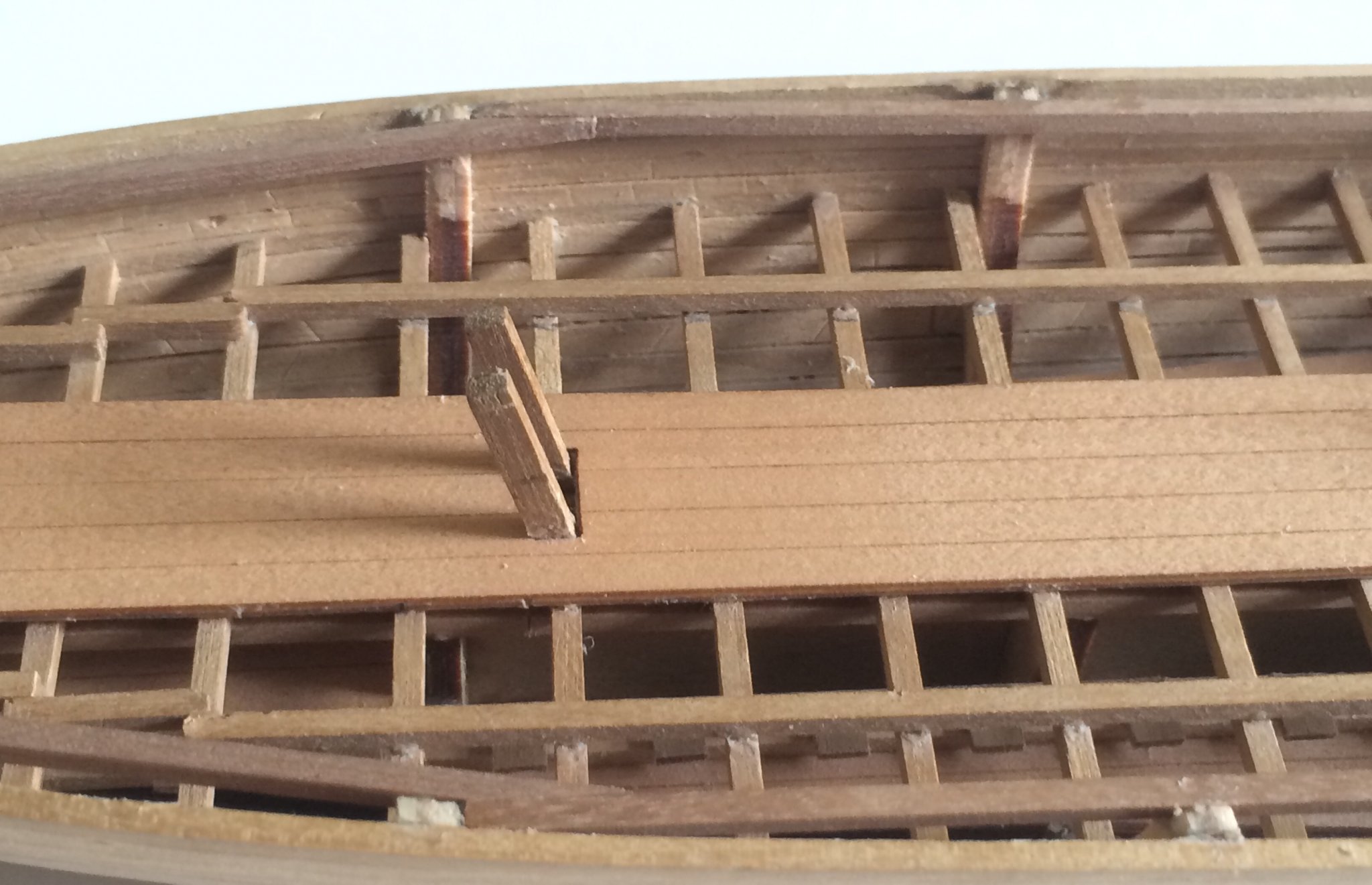
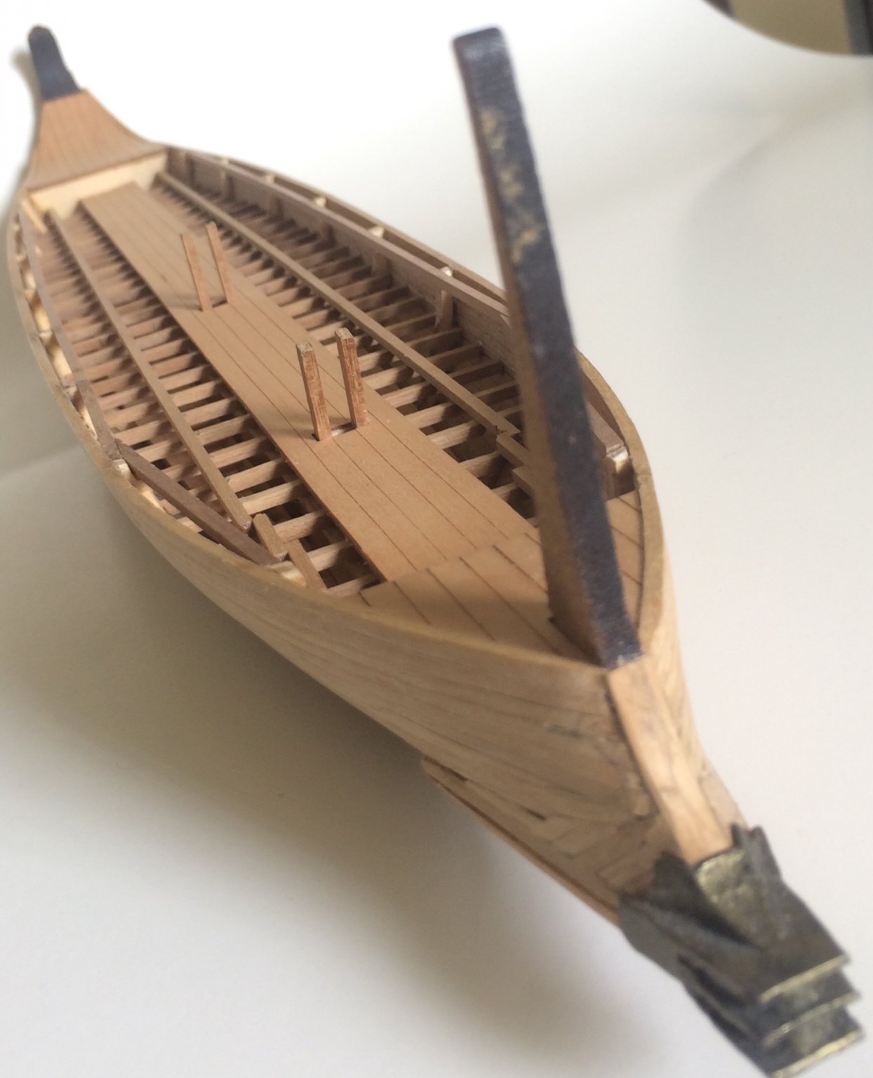
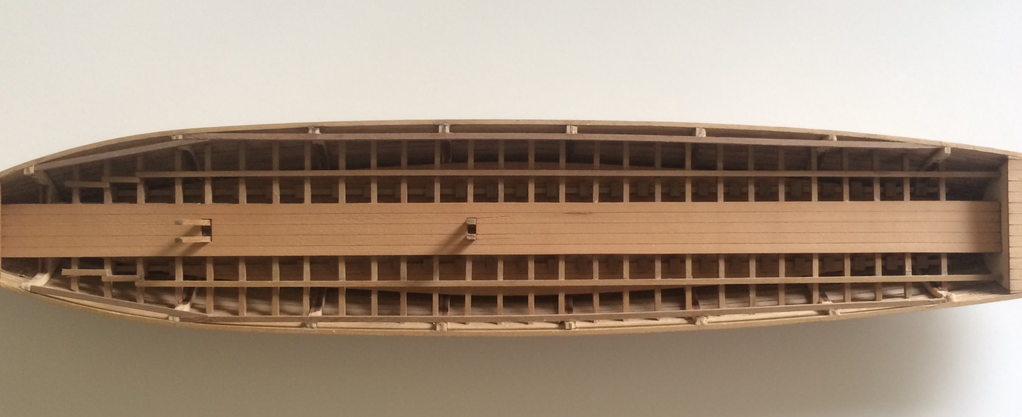
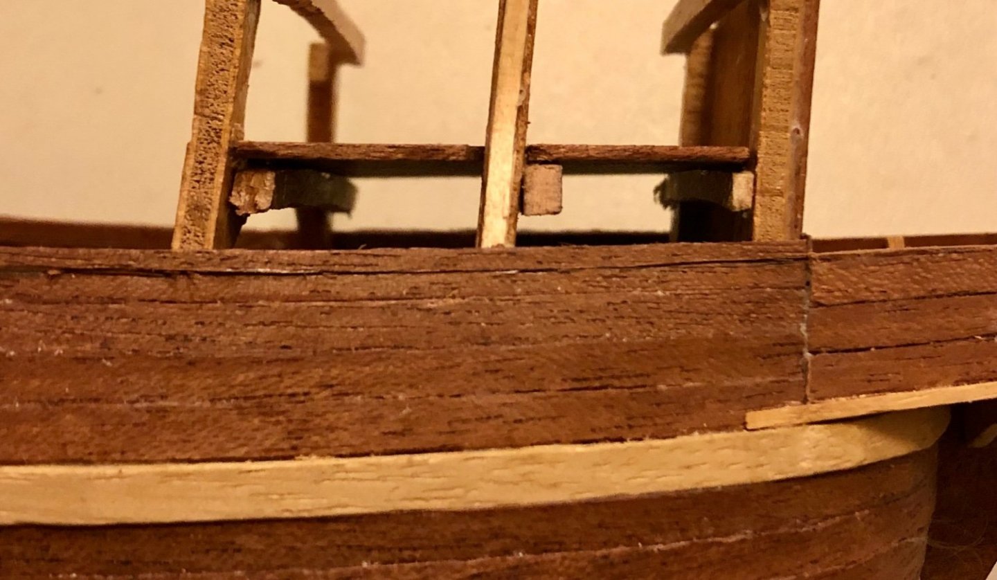
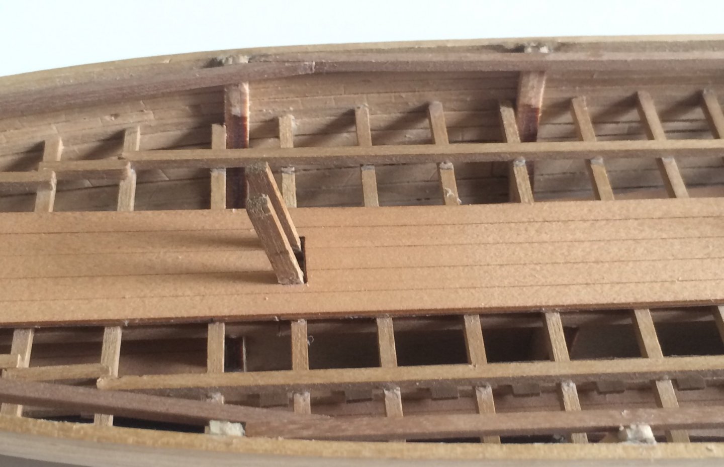
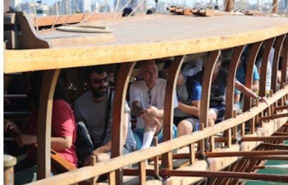
Added the outer/top level rower support beams. Looks to be reasonable & logical enough. It resembles a bit of life boat type bracing (which adds hull structure integrity & strength). Not looking forward to cut all those needed little rower seats.


-
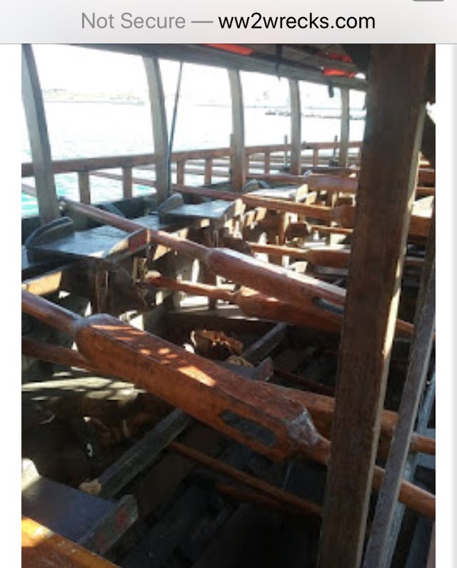
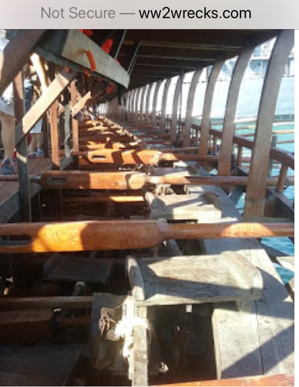
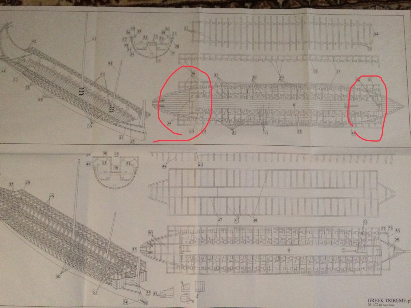
The Olympias'outer/top level rower's seat arrangement pictures can be found on this website. http://www.ww2wrecks.com/portfolio/olympias-a-2500-years-old-ancient-greek-trireme/ Below are few pictures from the website clearly showed those seats are parallel to and within the hull. In addition, some showed the oars and the rail system they rested on.

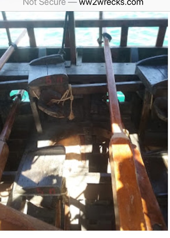
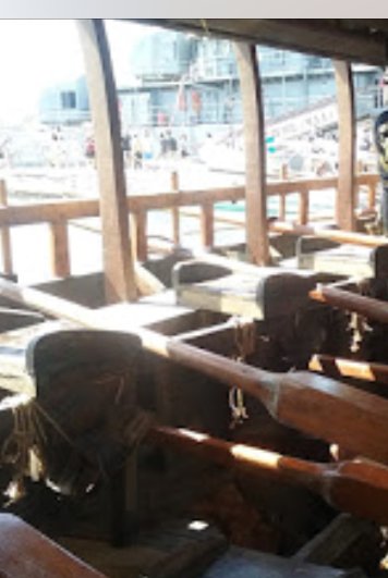
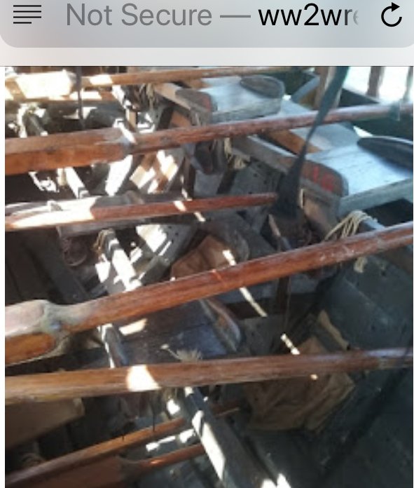
-
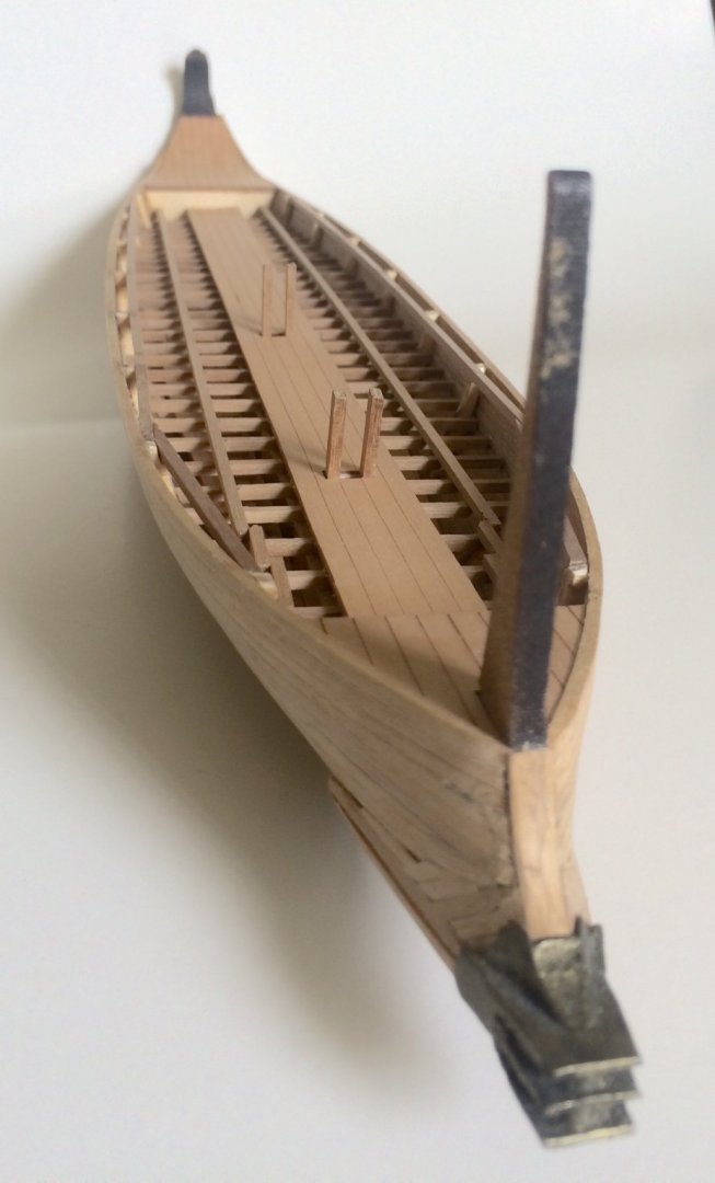
It seems the Duesk's kit plan and build instruction for the top deck (a straight rectangle) is to ease the construction process for the model maker. However, I don't think this will result in a realistic trireme model. The build plan would have some of the top tier rowers actually sitting outside of the hull (see highlighted area). The stern upper deck would also protrude too far out of the hull if built as the plan/instruction indicated; this would be a huge liability for a war ship uses ramming as the primary weapon. There is a customer model built pictures from Mr. Cryns of Amsterdam on the Duesk's customer's photo section - customer page #4 http://www.dusekshipkits.com/greek-trireme1 . He did a great job making a modified trireme model from the Duesk's standard built. I watched the Greek Trireme Olympias on YouTube videos and viewed the Olympias' detail pictures and have few personal thoughts about this life size trireme: Olympias has very nice curved outer supporting structs to the upper desk. However, Trireme's purpose is a warship where hull strength, minimization of unnecessary weight and speedy ship building are the top priorities. I doubt visual ecstatic would be a priority at time of war in accident Greece. The mast rigging on Olympias such as the use of dead eyes, belaying pins and rack would not likely to be found on an accident trireme. I think I will continue my trireme build somewhere between Mr Cryns' interpretation and the Trireme Olympias as there isn't a definitive trireme plan to base on.
-
I will see if I can restart this build in next few weeks..
-
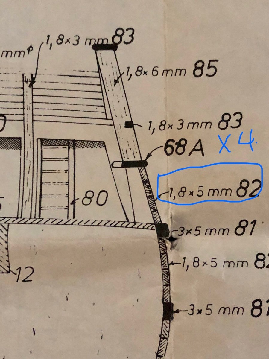
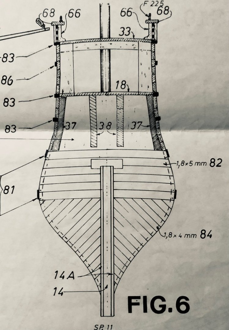
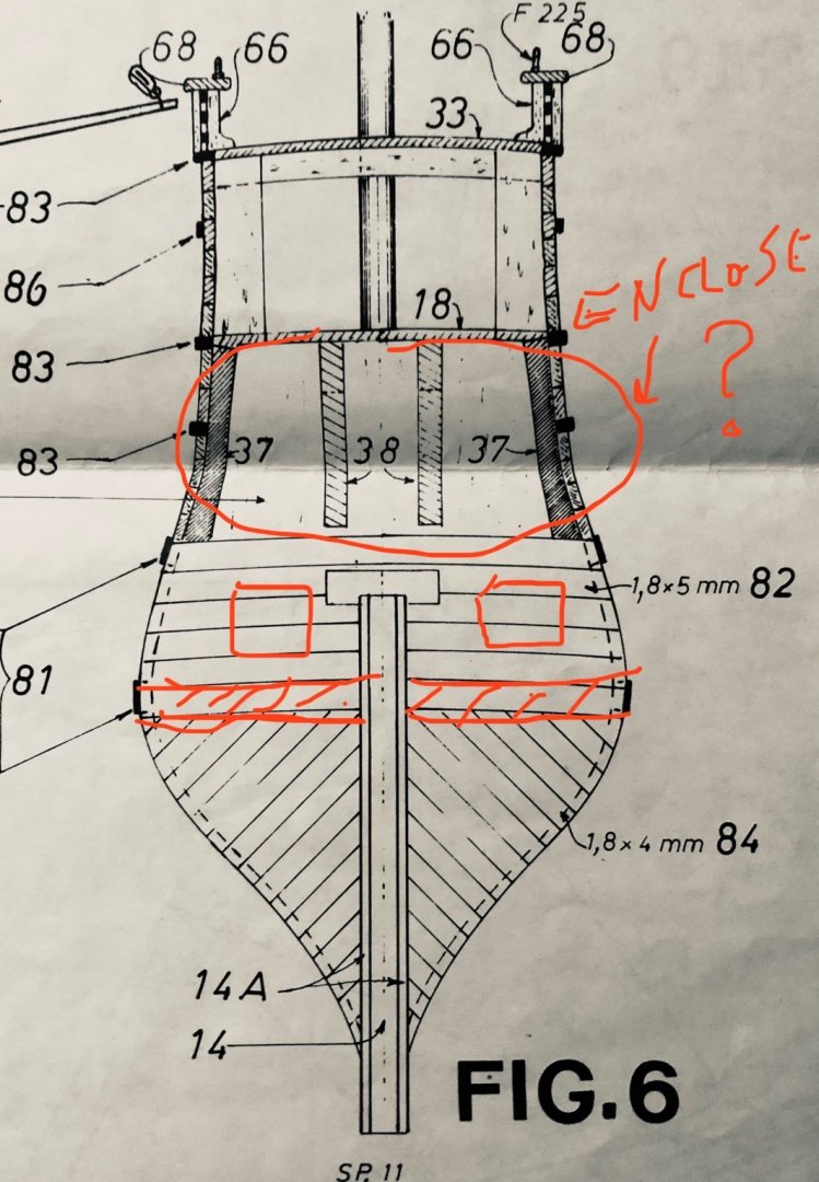
Just follow the enclosed drawings closely (especially TABLE A drawing - has most of the overall information) if you are not sure about the exact dimensions for the component or their placement. Match the parts/components against table A.