ships88
-
Posts
78 -
Joined
-
Last visited
Content Type
Profiles
Forums
Gallery
Events
Everything posted by ships88
-
 Yeah.. life is unpredictable... Wife gotten very sick ... everything is on hold. I will try to restart the build later this summer.
 -
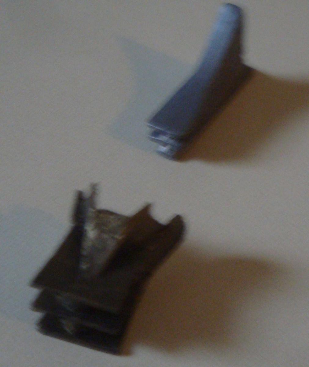
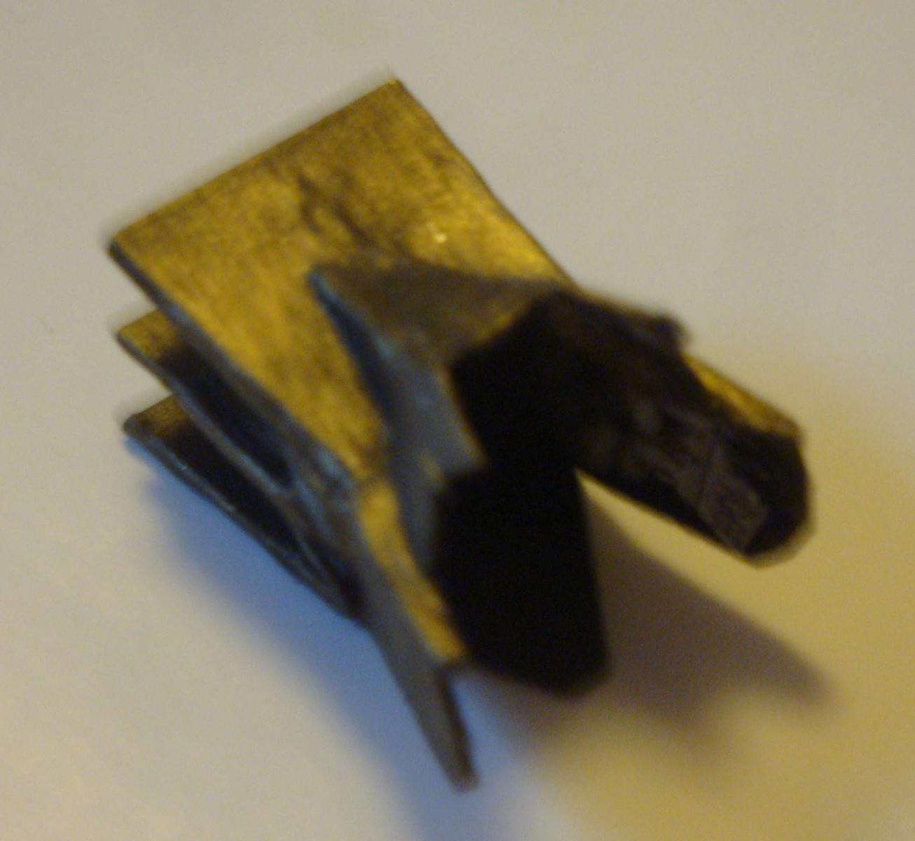
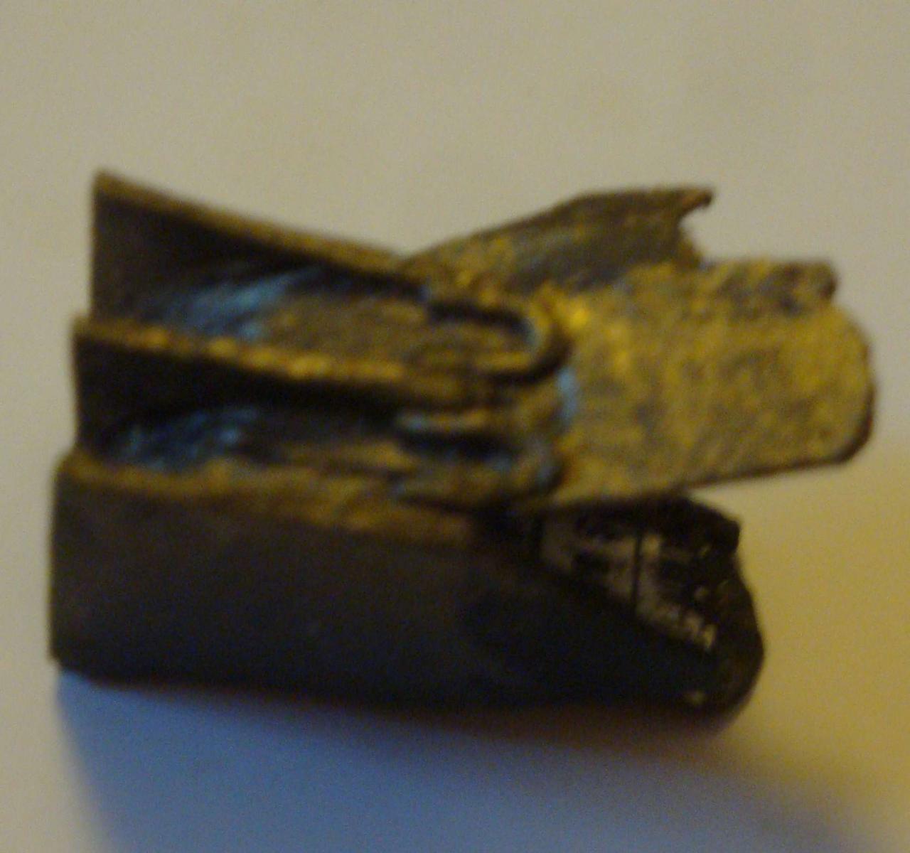
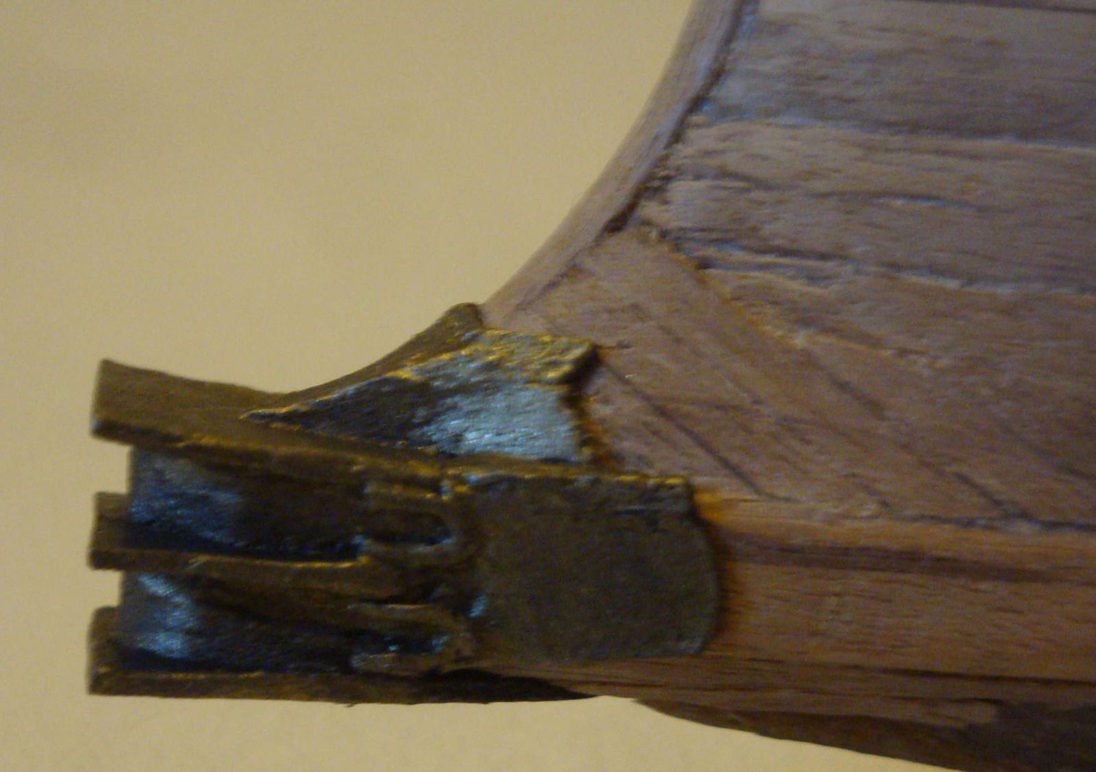
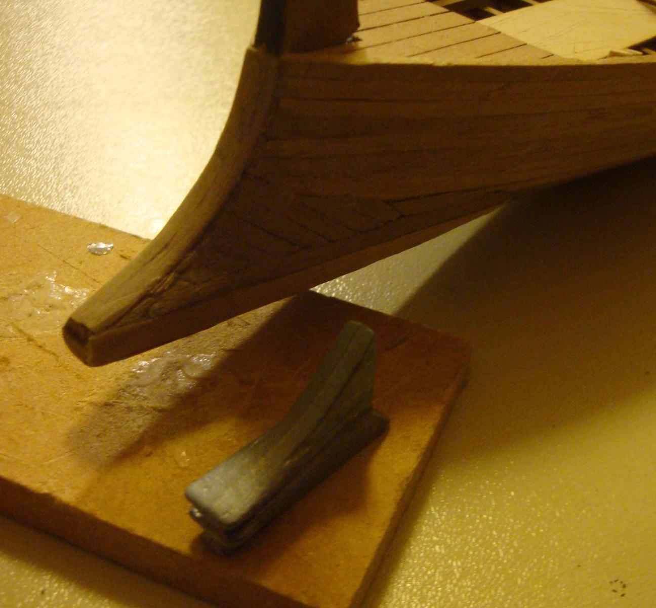
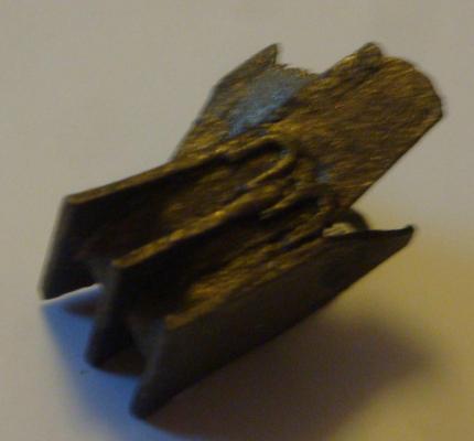
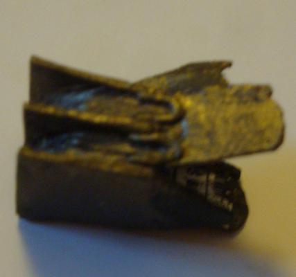
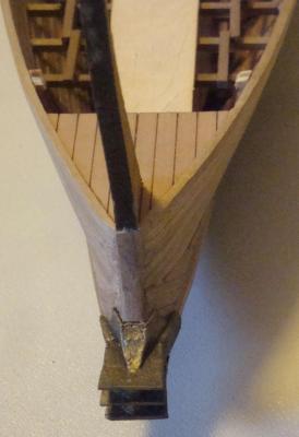
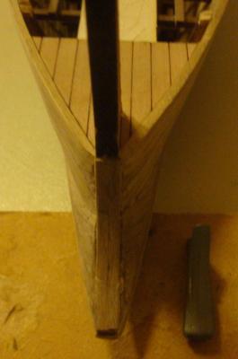
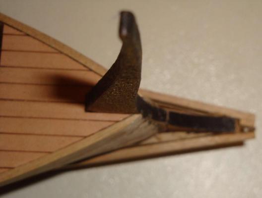
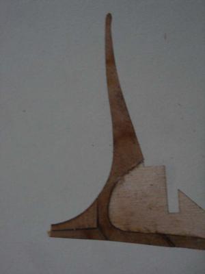
I first brushed on a black base coat paint (Americana - DecoArt acrylic paint) over the card board ram. Once the black paint dried, a mixture of Ceramocat metalic14k gold acrylic paint #02604 with small amount of the black paint (which makes a nice bronze color) is brushed over the black base coat. The acrylic paint coats also strengthens the cardboard from absorbing moisture in the air. Both paints were bought at the local Michael's craft store. They should be readily available at any craft/paint stores.I I originally thought about using some type of soft sheet metal as well. However, after researching the Trireme ram images on Google, the actual ram has too many corners and edges, making it impossible to replicate with sheet metal in miniature. I believe casting method is the only way suitable to recreate a miniature metallic ram.
-
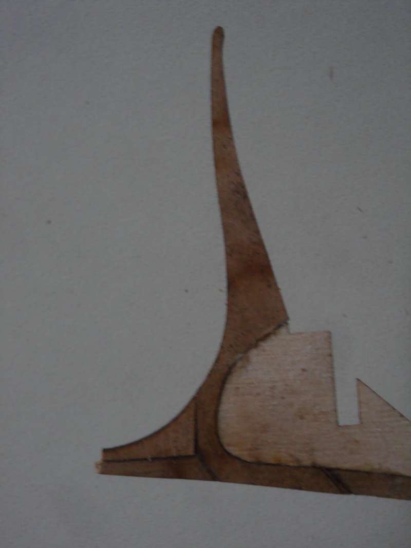
Because of the small size of th ram and th slopping angle, it was impossible to make a single piece ram. The ram was constrcuted in mutiple pieces. The easiest material to make this turn out to be ----cereal box . The pieces were cut to size against the hull and glue together (make sure no glue touches the hull) . Once dried enough, removed from the hull and painted with bronze color paint. It looks realistic enought. This tririeme is unlikely to use it's ram in action anyway.


-
Narrative will be uploaded later.....lots of works, modification, time and patience needed to make the ram. Guess what the ram in the picture is made of ?

-
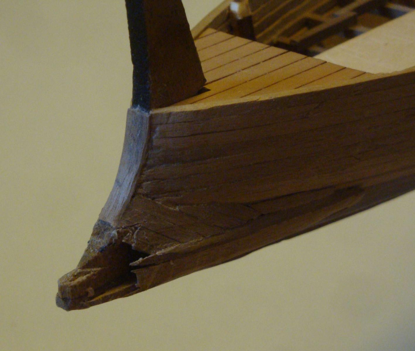
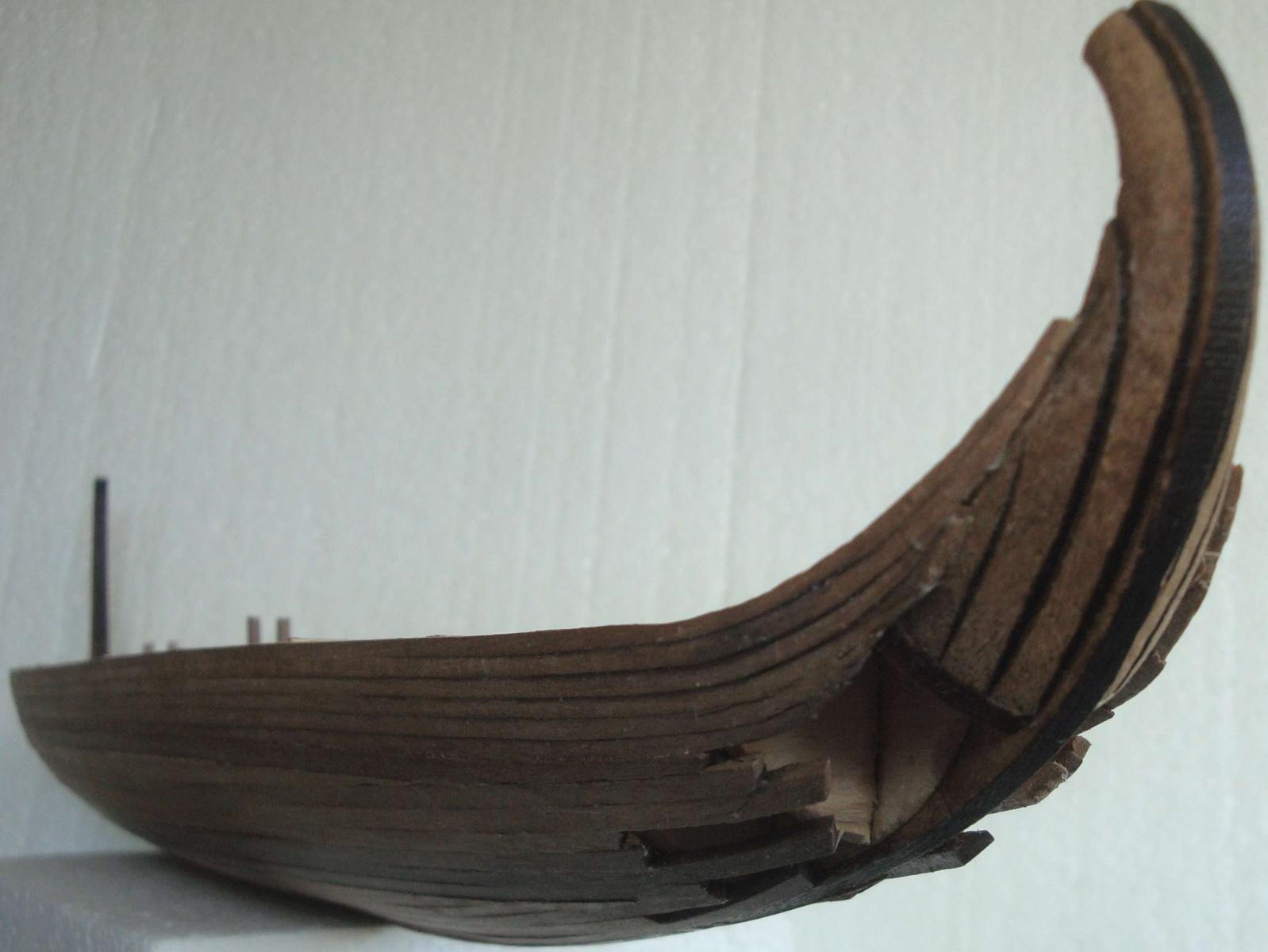
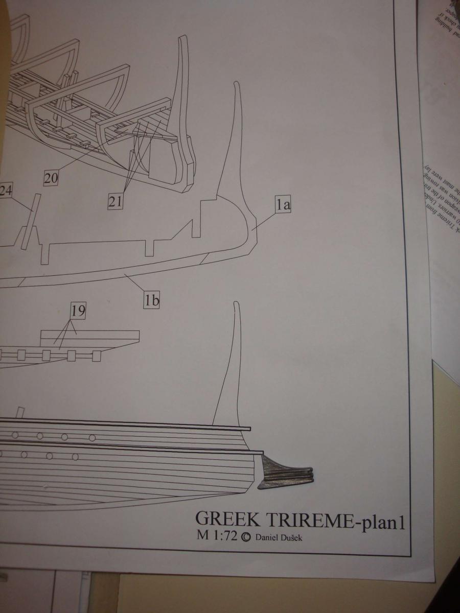
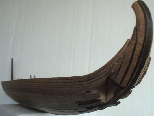
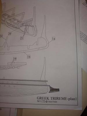
This kit's weakest area is the ram. The kit provided a nice metallic ram. However, the trireme's ram is more than just the frontal metallic ram casing that covered the foward portion of the massive ram structure. The construction of the ram is the hardest part of this kit. It was hard to get sufficient information to correctly scale the ram size as the kit's depriction of the ram is incorrect. The Olympias trireme gallery picture was used the refernce. for the scaled size estimate . The front portion plankw are rough, but they will not visible once the ramming casting is place over it.


-
Did not have time to work much on the ship. text will be upoaded at a later time.
-
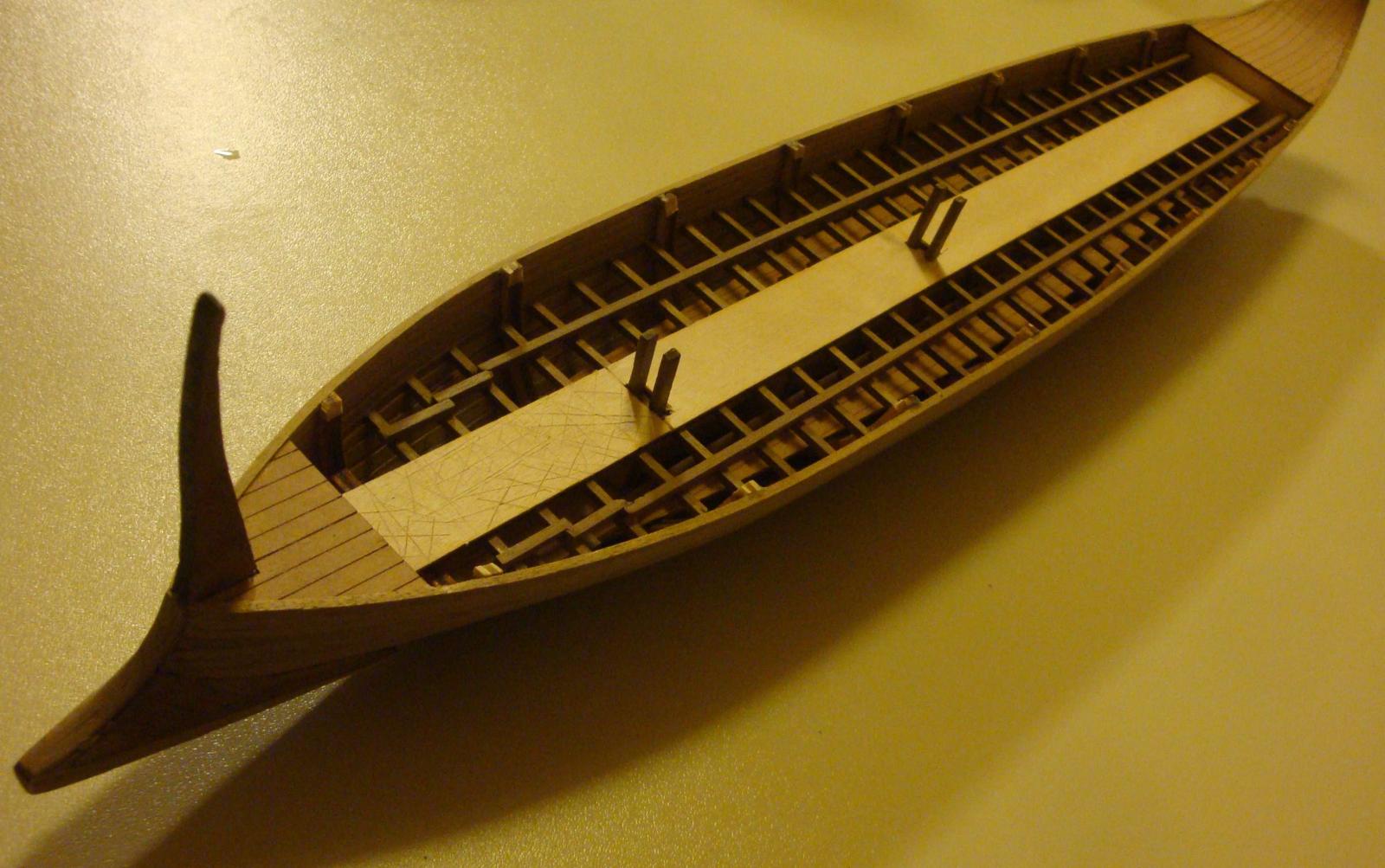
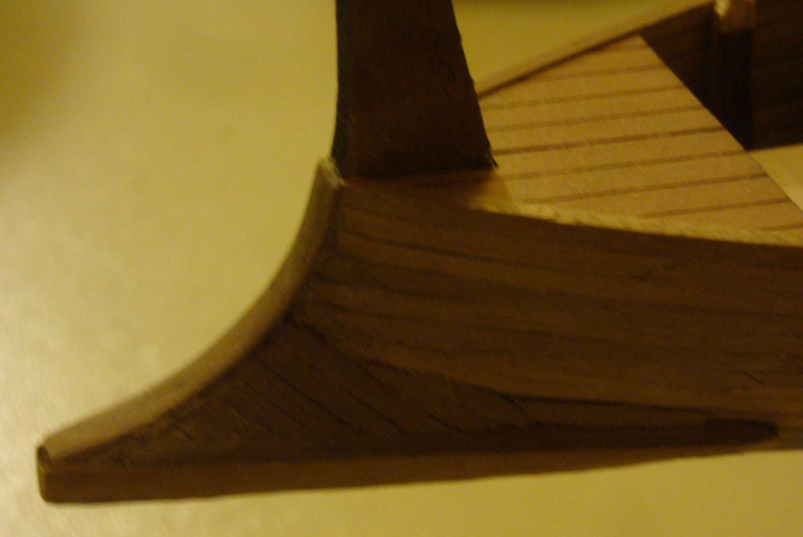
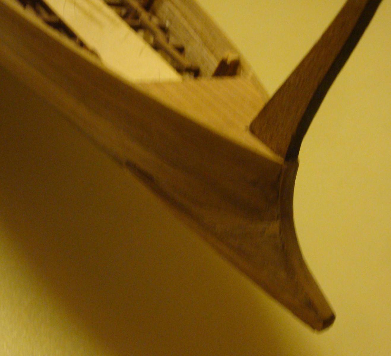
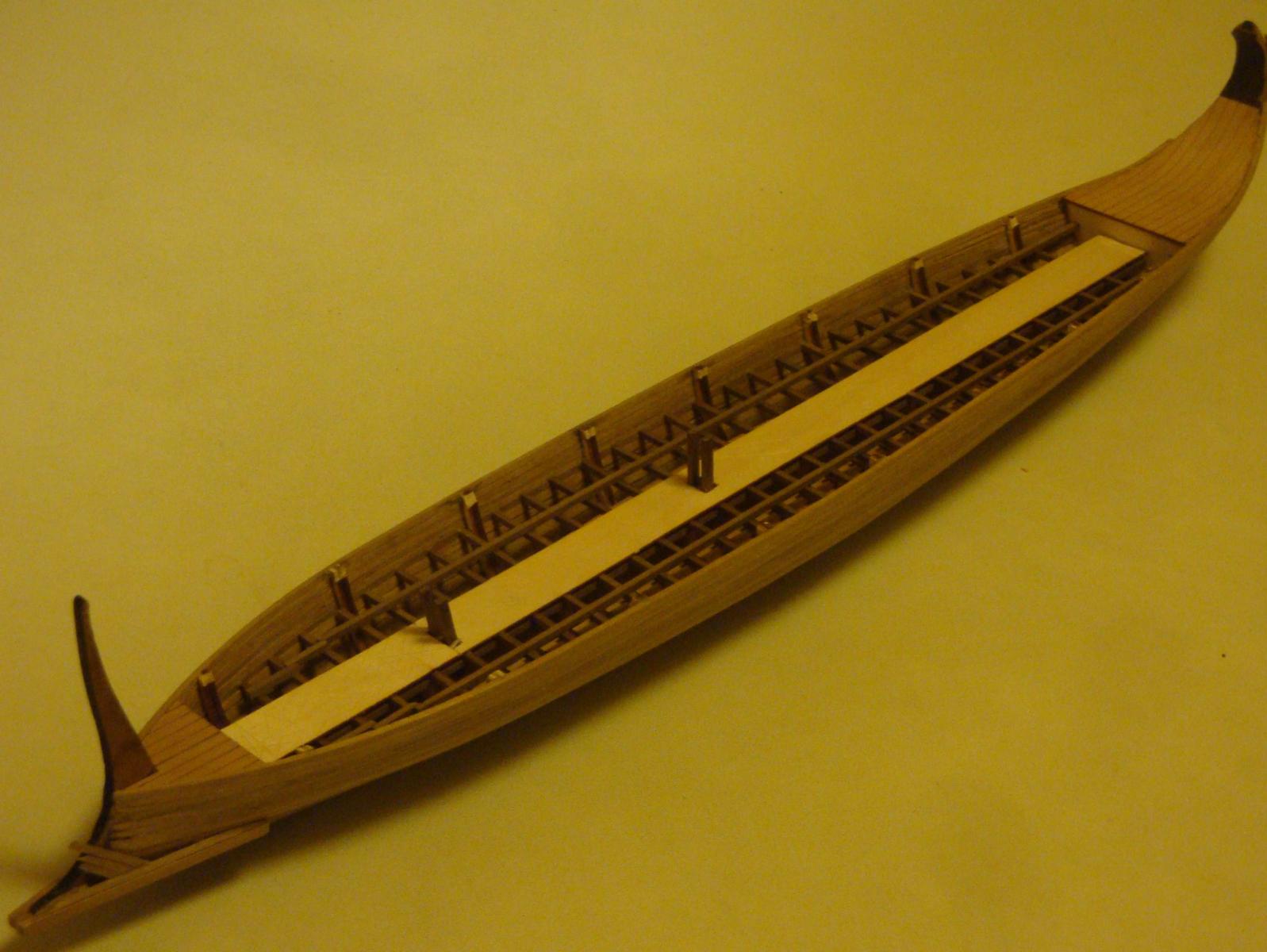
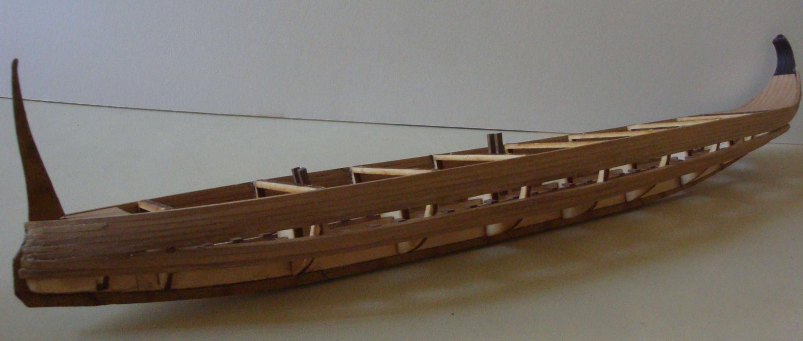
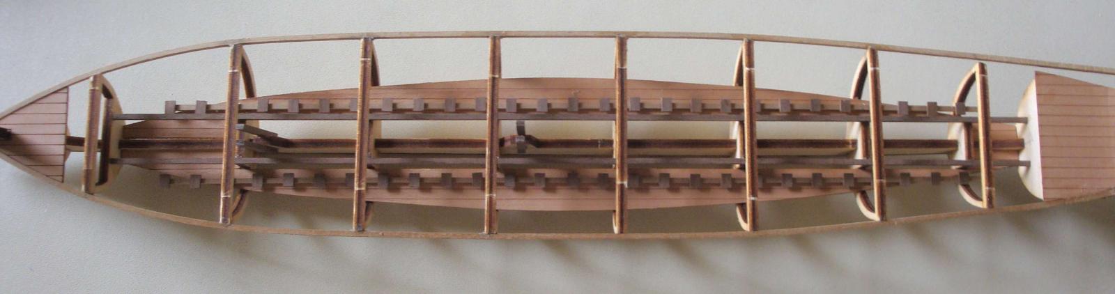
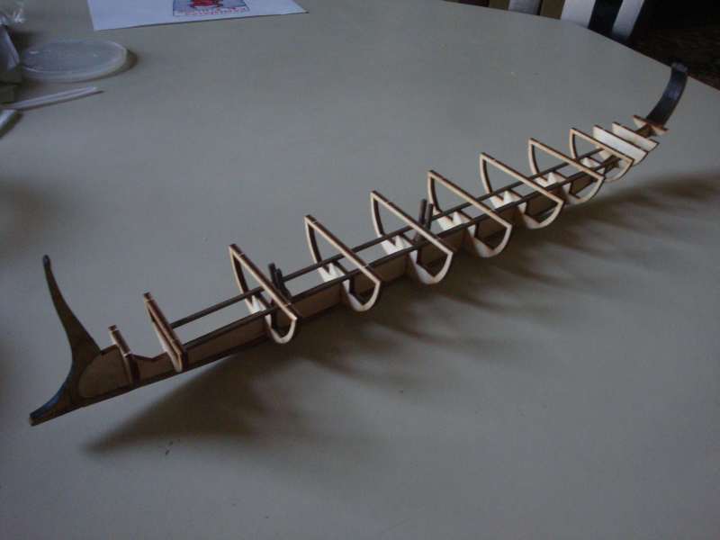
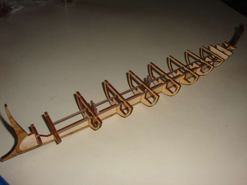
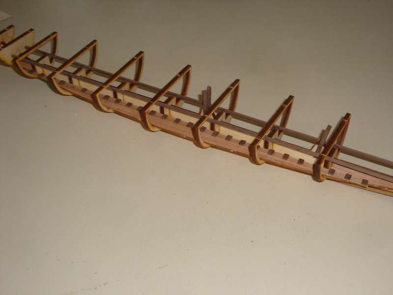
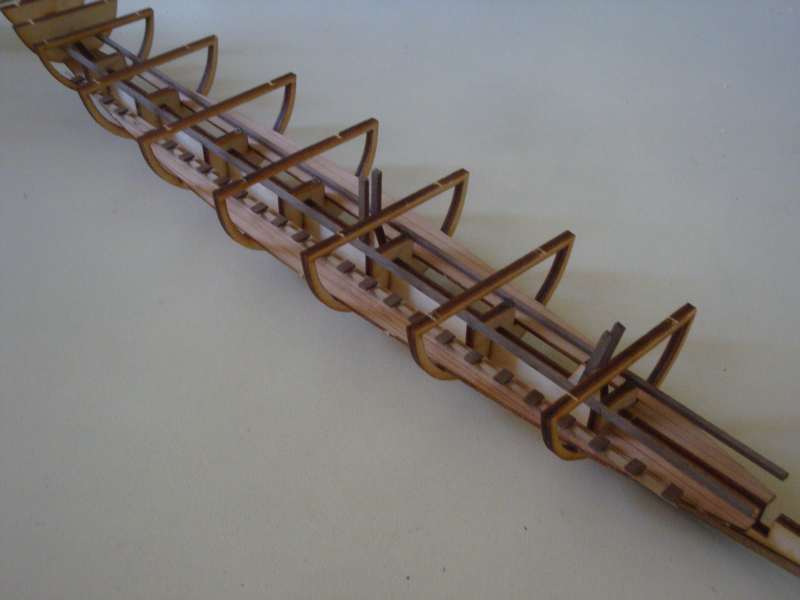
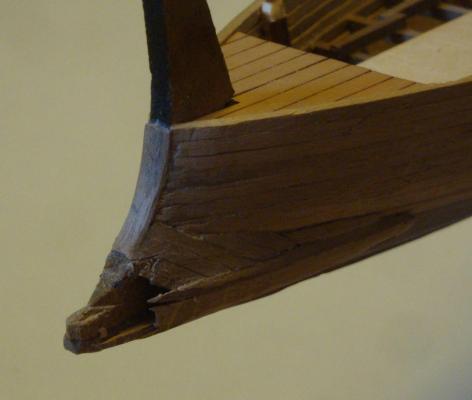
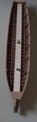
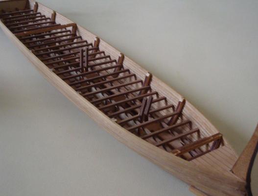
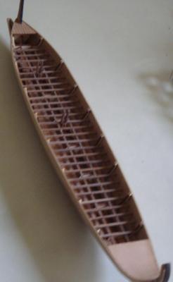
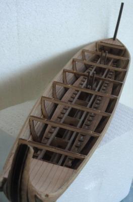
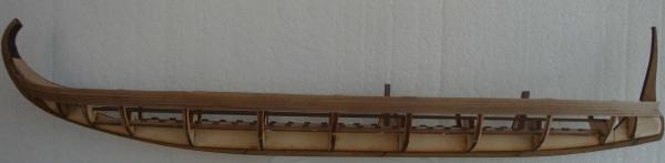
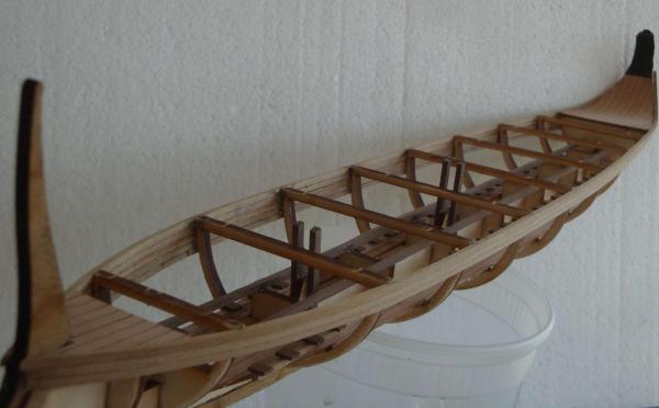
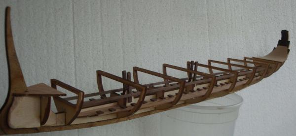
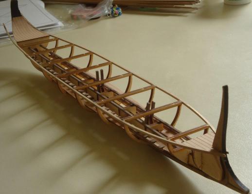
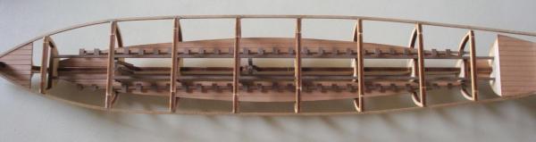
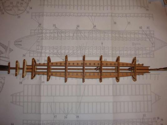
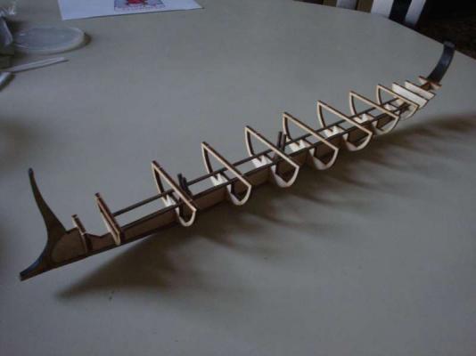
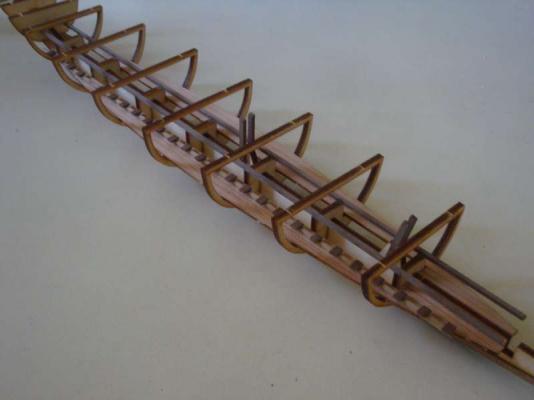
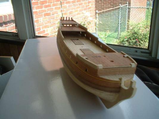
Sanded the hull and tried to fit the ram support to the hull. First attempt defining the ram side support lambers proved too small. The second attempt ram support seems to be the appropiate sized for the ship (both ram attempt supports terminatesd on the same point on the of the center line ram outline).The plan provided a drawing detail of pre-built the mid level rowing deck and beams. The intend was to buit the row deck outside the hull, then drop the assembled row deck unit into the hull and glue it. However, unless you have a perfect hull build, there will be gaps between the pre-assembled row bean and the hull planks. I decided to cut and place the row bean one at a time. This meant each bean will be trimmed individually to fit (touching the hull on both end- make sure the bean is cut at an angle to fit the curve of the hull).

-
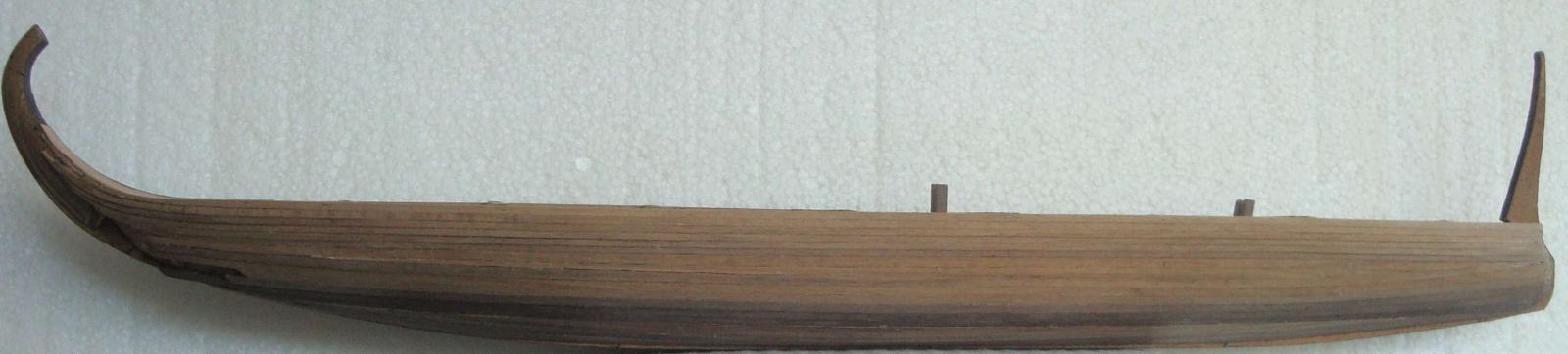
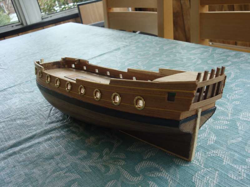
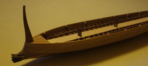
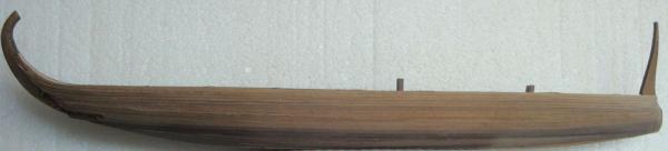
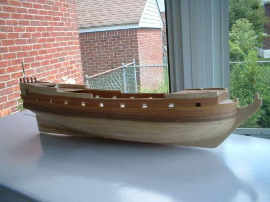
The hull planking is completed,..sort of,,, the stern will be a challenge. This was unavoidable in any case, as the kit supplied planks are not long enough to wrap around from bow to stern. Wish me luck to some how tie everything together to the stern that would look reasonable...LOL
-
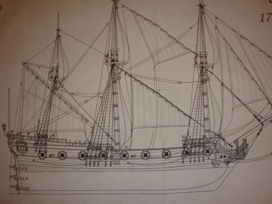
Hi Ron, Thank you for sharing your evaluation of the La Reale. Can you advise where you purchased the kit from ? In addition, how do you think this kit compares to the classic Corel's Reale de France ? I am looking forward to see the pictures of your built (would really love to see you start a log)>. Thank you.
-
Hi Hans, The quality of the aeronaut kit is questionable to me, I have read mixed reviews onliine (in general of their kits), In addition, there are vitruallly no retail outlets in Norther America that sold their kits. La capitana seems to be nice from the limited number of picture available (there does not to be any build log or finished model picture other than the company's advertisement pictures). It is an older kit and does not seem to have the same level of details as the new LaReale kit (similar pricing for both kits). Back to the build: Completed ed the 6 course of 2x2mm planking. The plan drawing shows all the planks are nice line up in a perfect straight line. The first 2x3mm plannking proves otherwise. This is a single plank kit, so how the plank is layed in is how the model will look. The 2mm thickness of the single plank is much harder to bend than the double plank method, but it does save alot of time (no second planking needed).

-
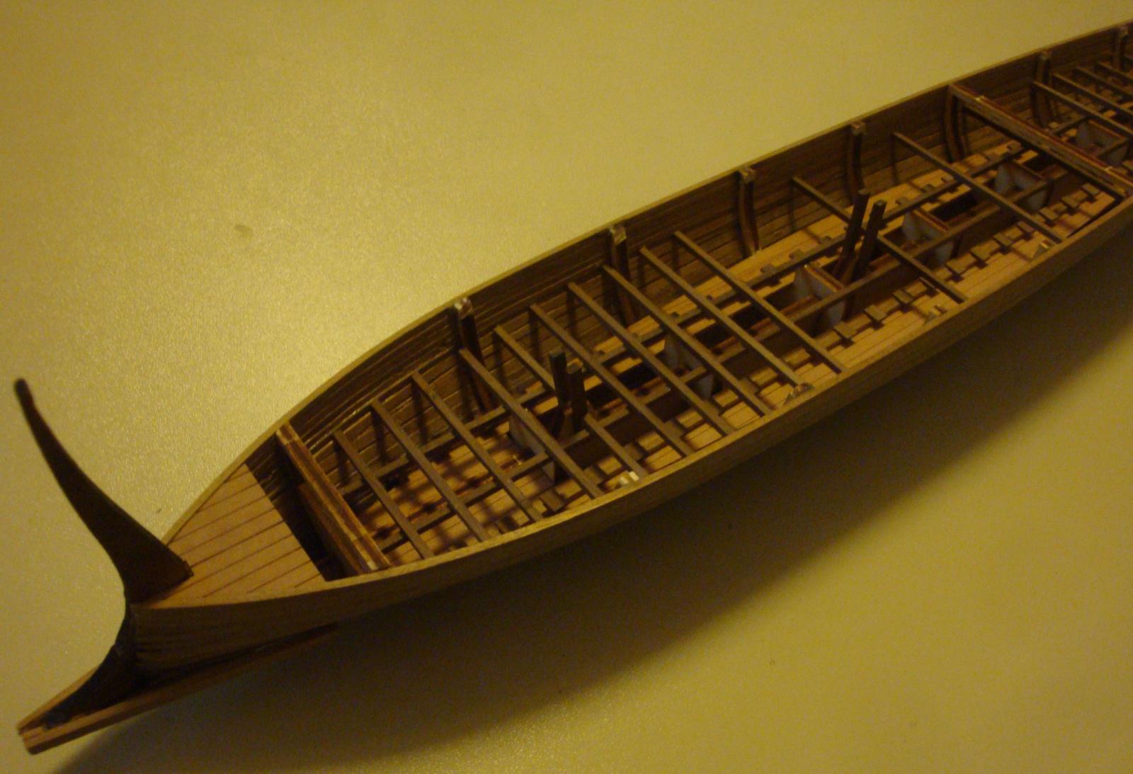
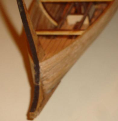
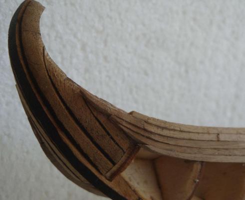
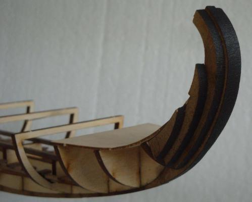
Sharpie, Thank you for the excellent Trireme web link. Richard's (an UK naval architect at Plymouth) trireme build log clearly demonistrated how the Trireme bow and ram are constructed. By following his research and build method, I believe the finished model will be greatly more accurate than the completed model shown on the deusek web site/box top picture (especially in the ram & bow area) The kit calls for the first top 6 rows of planking to be the 2x2mm, while the rest of the hull planking downward to be the wider 3X2mm stock. Both are not long enoguh to cover bow to stern. Also they are hard to bend (even after soaking in water for a while) due to the the thickness. Few things to remember: Make sure to bevel slightly the top edge (inner side the plank that face to the bulkhead) of the plank to be install (except for the first plank), otherwise because of the plank thickness it will leave a gap on the outer hull against the previous installed plank. I also found it was easier to glue the front half of the plank from the bow to the mid-ship, wait after it has dried, then continue to test fit, adjust the hull bulkhead sharping to align toward the stern then glue in the remaining half from the mid-ship to stern. In this process, the most challenging part is the cuvring and shaping of the plank at the stern (make suer alot of clamps are on hand), As the supplied planks are not long enough, I decided to to a shorter curve(which looks right), and using lower hull planking extensions (which is not as visible) to complete most of the stern curve tail. The trireme is one of the few ship model where the intern hull are visible after completion, So make sure that the internal hull are free of glue overrun, excessive trim marks and that it is reasonable in "appearence". This is apparent on the fifth plank toward the bow, I notched the plank in 2 areas to make the bend, I should have notch more areas and smaller notches so it wouln't be so obvious. BTW- I temporary removed the ram section to make the planking process easier,
-
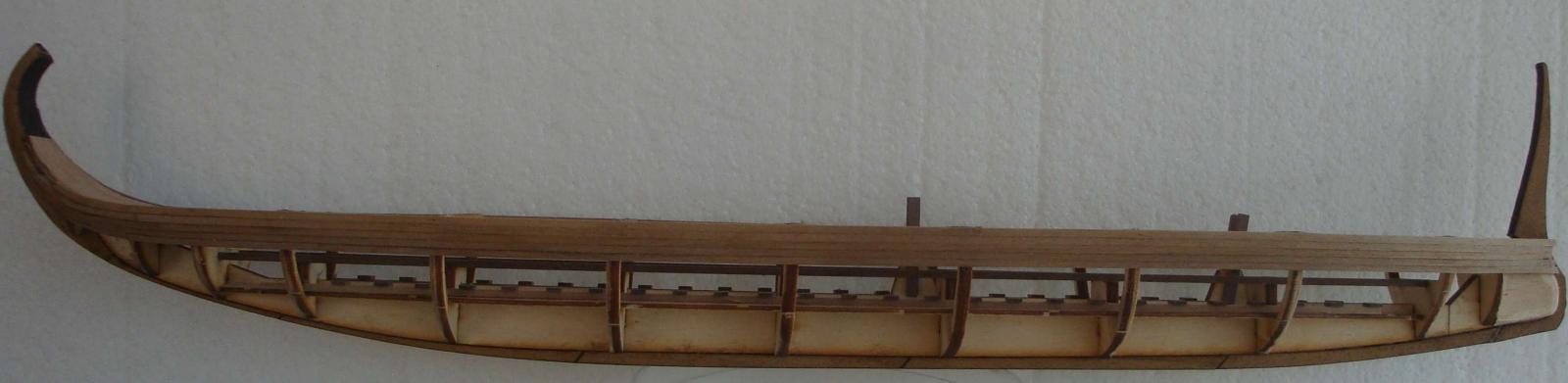
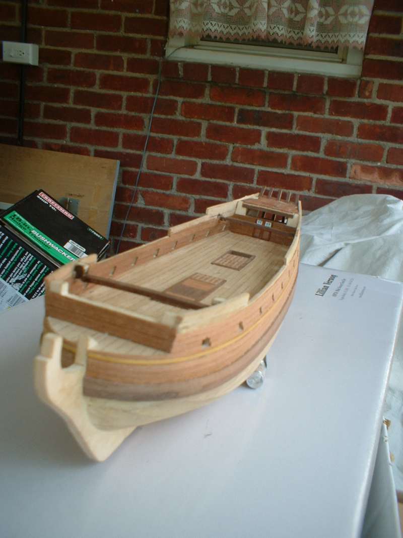
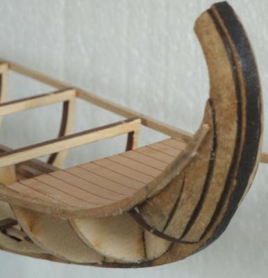
Thanks Sharpie. You have an excellent trireme built/model. Any advise on the stern tail planking and reduction ? The stern blocks glued in place and shaped to the rounded shape. The laser cut burnt marks on the stern block comes in handy to visually indicate how much material has being removed and the continuity of the curve. Set the the bow and stern deck. The stern is a bit tricky because of the curve shape. The false deck was scored horizontally from the under side. This made bending the wet deck possible to the stern's curvature. The kit supplies basically two type of planks for the hull, 2mmx2mm (Amati stock - 100 pcs) and 2mmx3mm. Those are a bit thick to bend for hull (a thinner plank or double planking would have been perferred). One thing become very obuvious,,, the plank length is no long enough to go from bow to the stern curve end (oh boy). In addition, the reducing of the hull panking to the stern curve(both thickness and width) is up in to the builder's own determination. btw- the pictures are out of sequence irregardless how I uploaded them - not sure why.
-
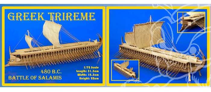
The Greek trireme was one of their earlier kit. I believe their best kit to date is the gallery - La Real 1571 http://www.dusekshipkits.com/larealE.html. It seems to be even par with the Corel's gallery - Reale de France. It is a bit shorter/smaller, it will likely be expensive also. I would love to have this kit (if price is affordable).
-
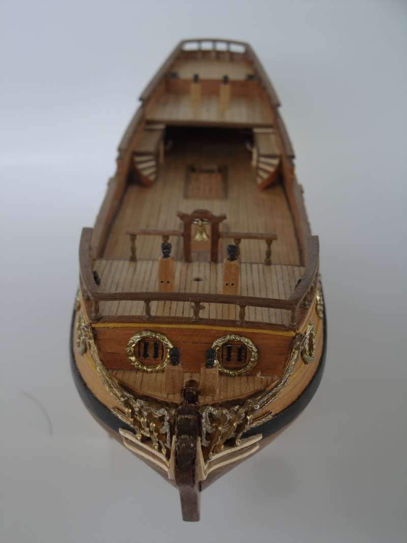
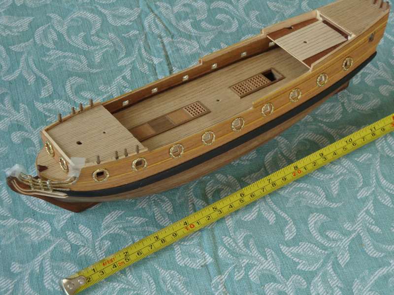
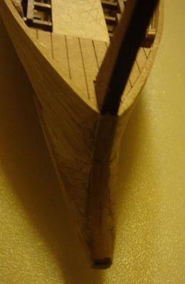
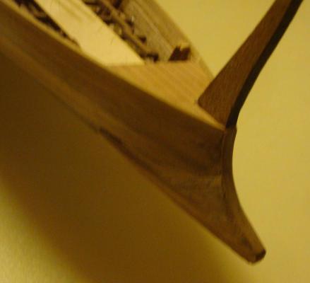
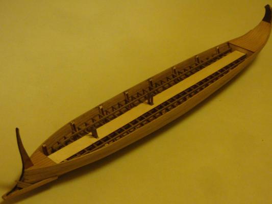
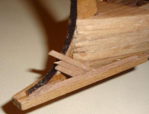
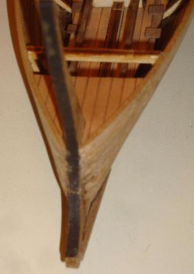
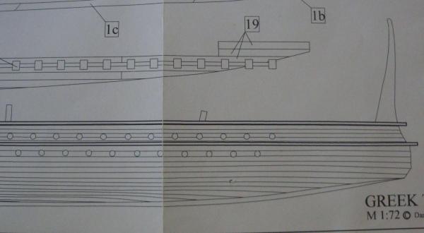
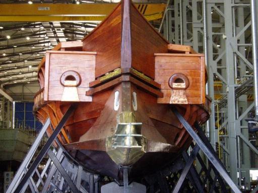
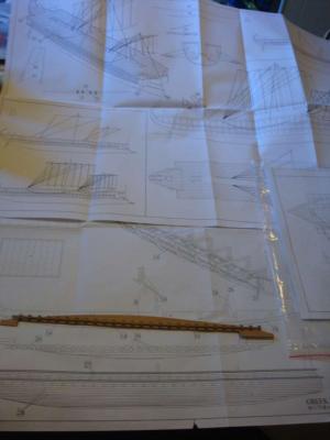
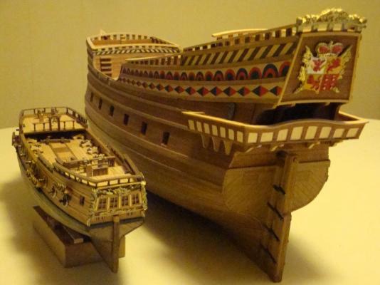
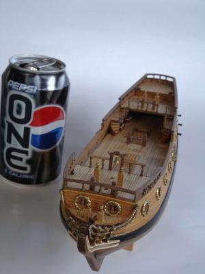
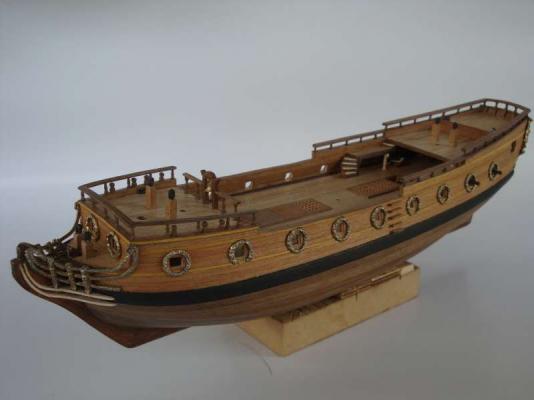
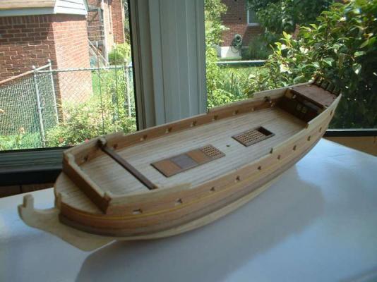
The kit's metallic ram has a nice side profile (it is shown on the right bottom corner of the kit ram picture) , however, the overall shape is rectangular tubular(same width from front to back). The greek ram is wider at the attaching point to the bow of the ship. There are also re-inforcement behind the ram(this is give the ancient ship their unique bow shape). This can be clearly seem from the front view of the reconstruction trireme ship- Olympia. The kit's plan or instruction does not account for the re-inforcement behind the ram. This omission and the metallic ram shape made the bow shape awkward. This is an easy fix by adding needed enforcement planking behind the ram and reshape or scratch bulld a new ram. Although the ship is about 20 inches long, it is about the same hull size as a 26 to 28 inches 18th century sail ship model (which includes the bowsprit and jib boom) as the trireme does not have those.

-
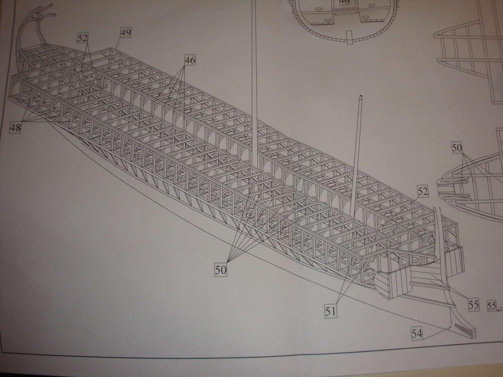
This seems to be the only available trireme kit. It is from a new Czech company - Dusek. I brought the kit because it is a trireme and curiosity about this new company's offering. The kit turn out to be much better than I expected. The laser cut bulkheads were nicely done, They fit perfectly without any adjustment. The plywood quality is very good. The laser scored deck verneer sheet was a surprise and superbly done. The wood verneeer quality is also top quality. The kit comes with a simple(not a tone of wording), yet effective illustrated instruction booklet. The 1 to 1 ratio plans made the built easy. There is one area the kit is lacking. The bow shape and the kit provided metallic ram is not satisfactory. Modification will need to be done to bring the model's bow to the correct shape (There is a modern full size reconstruction of the Greek Trireme- Olympias, which provides a very good reference for this- GOOGLE it)


-
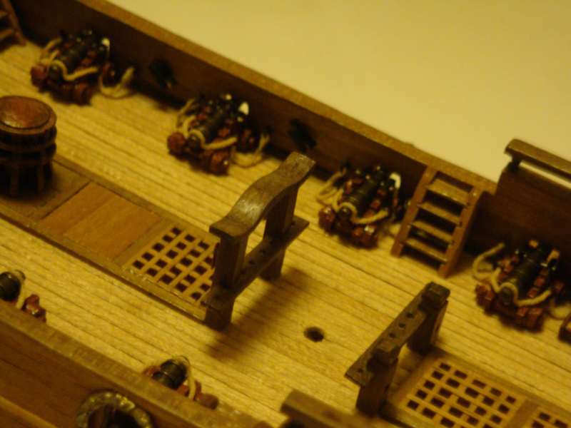
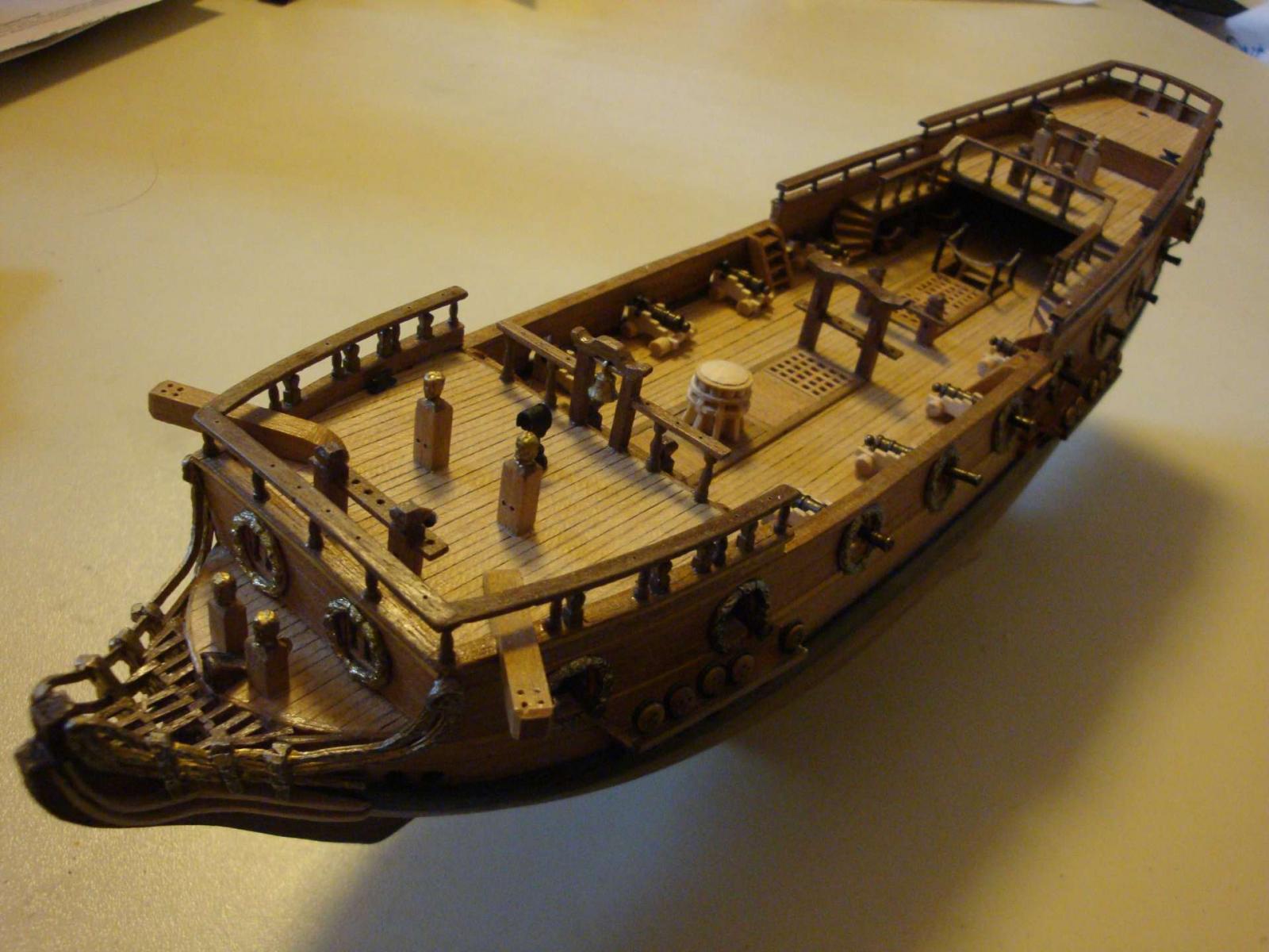
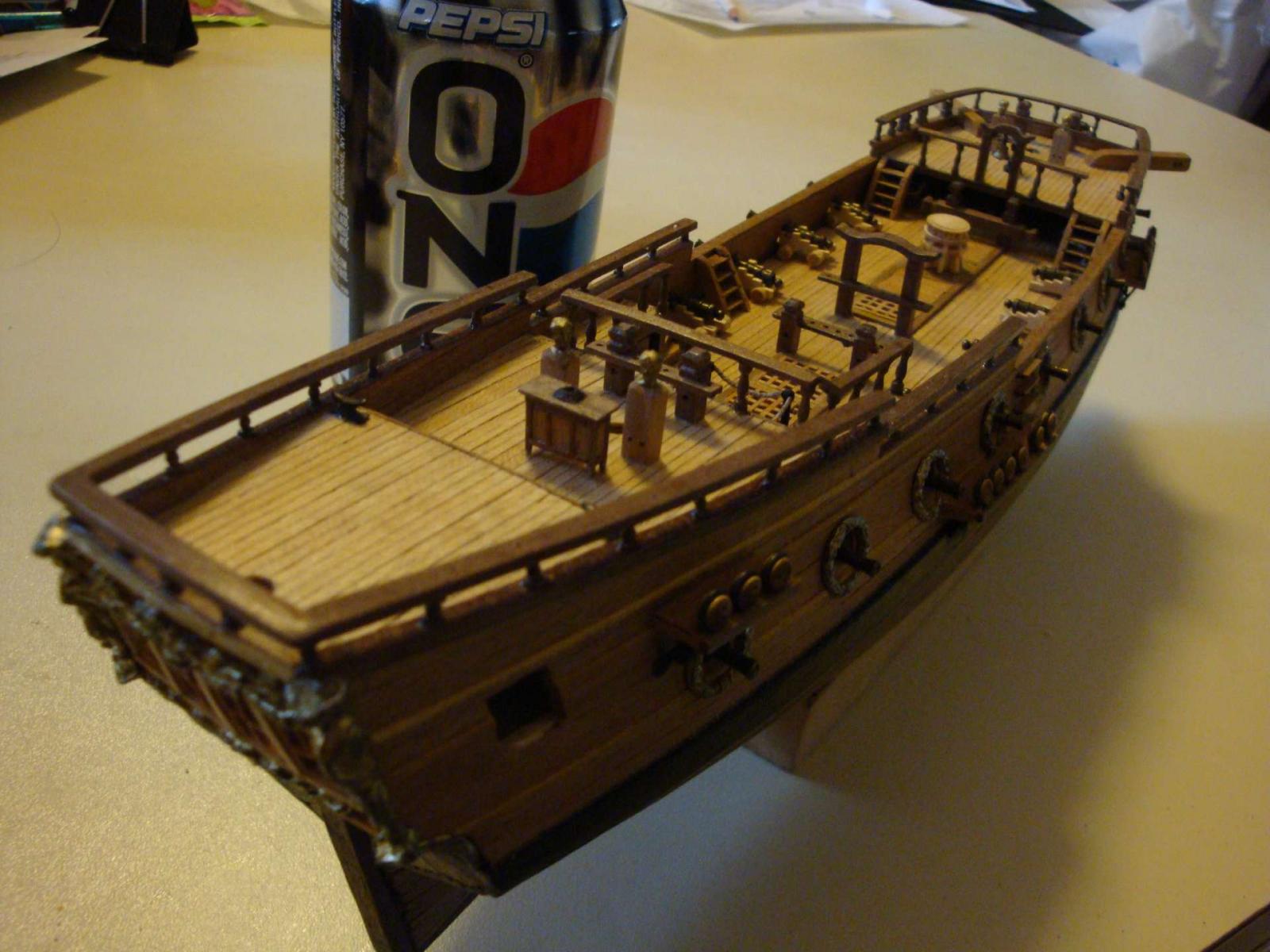
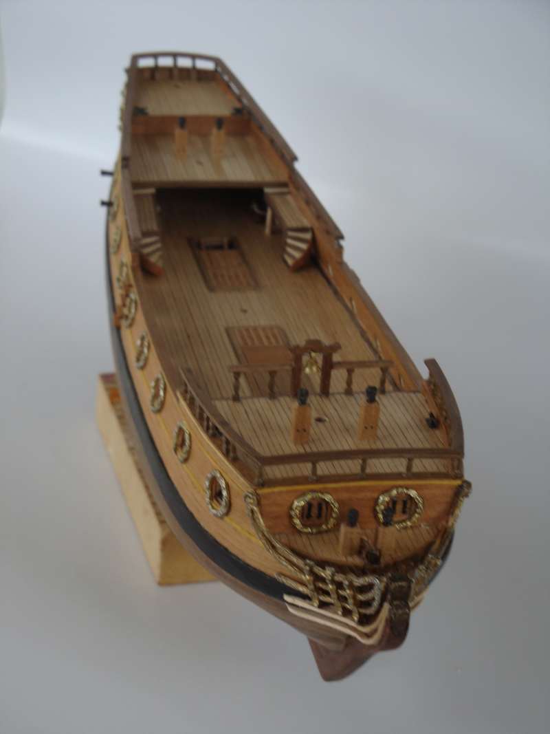
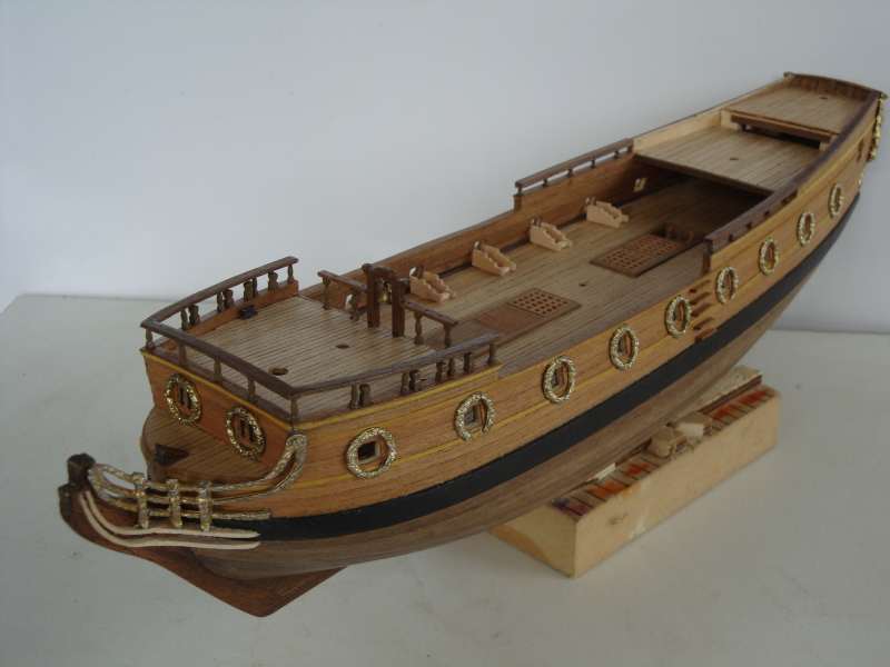
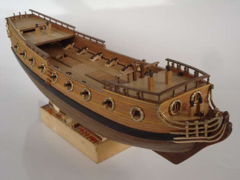
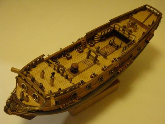
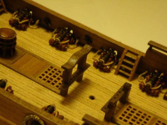
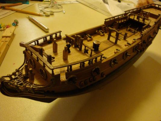
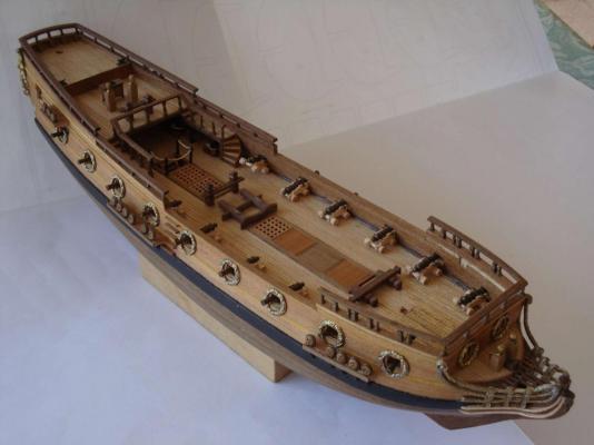
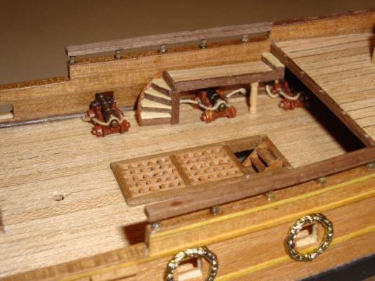
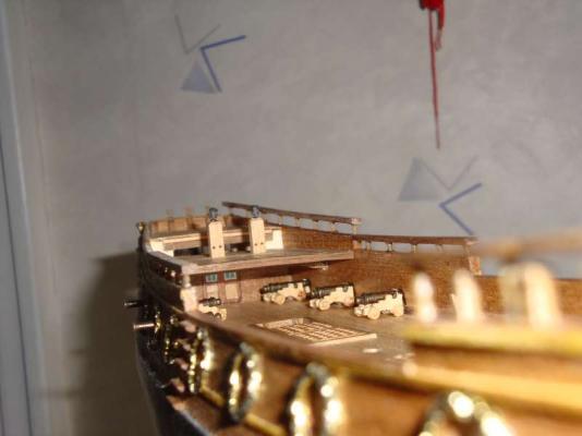
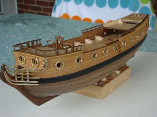
The rigged guns are attached to the bulkwark. Holes were pre drilled on either sides of the gun port for the breaching rings (make sure the hole's height are correct in relation to the gun carriage). The pre-rigged gun carriage are then attached to the deck and bulkeark using epoxy glue. This phrase took a long time to complete (be patient).


-
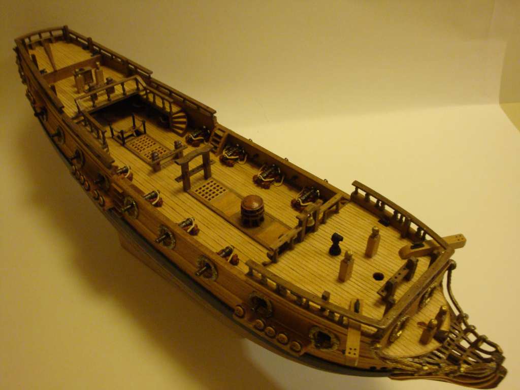
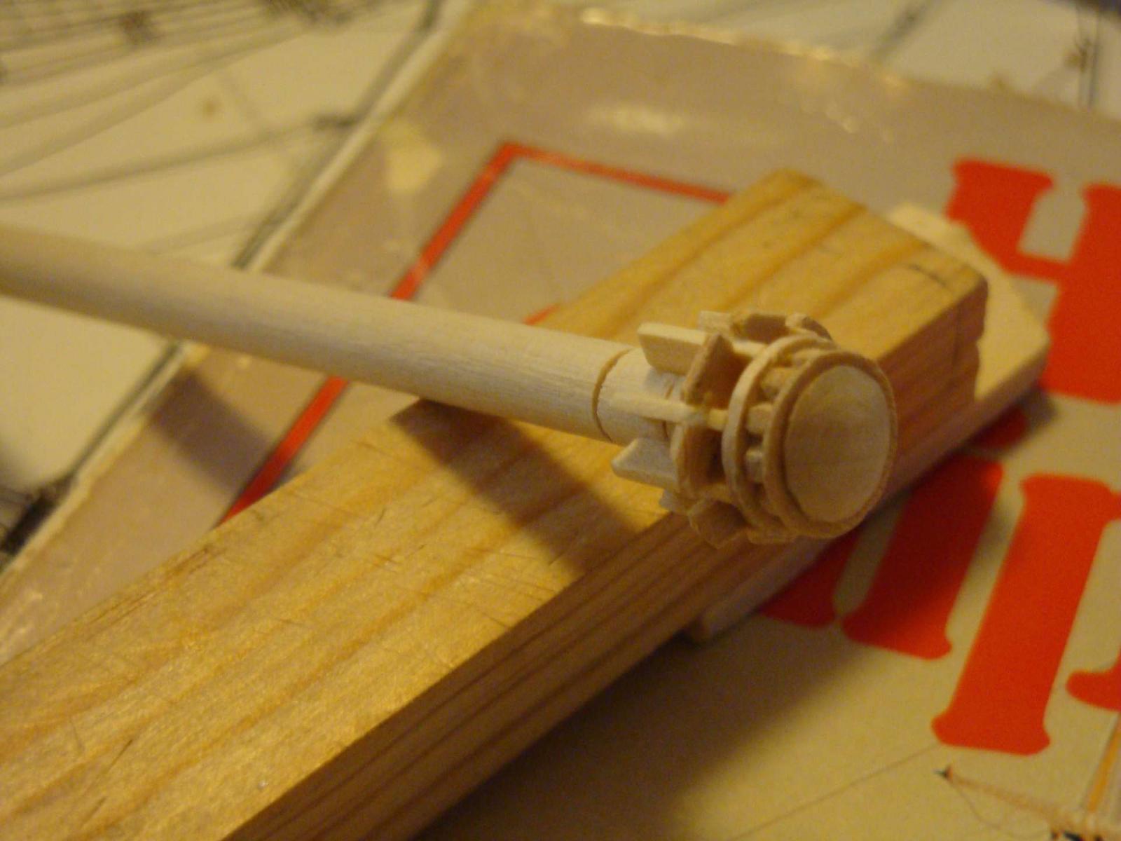
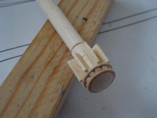
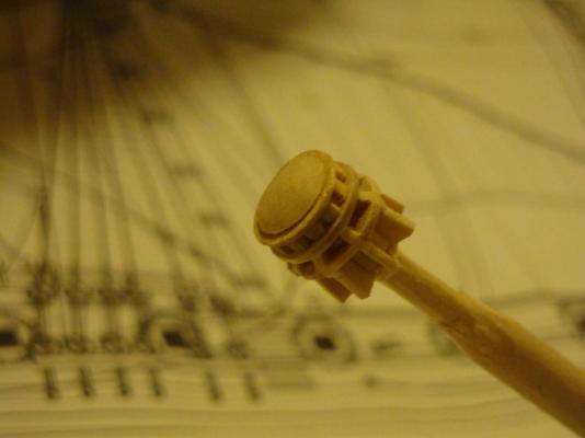
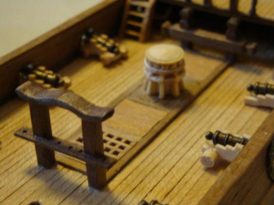
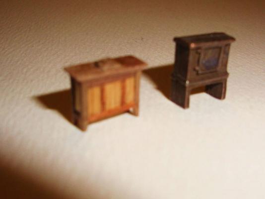
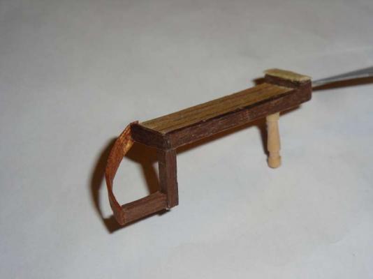
The metallic capstan provided in the kit is nice, however, there is a molding line run across the middle of it. It is very visible. Sanding the line away, making it shinlely and hard to paint over. A replacement was constructed from a popsicle stick and a coffee stirrer. The small size of the ship enabled this to be possible and inexpensive. The captsan was constructed using the construction drawing from the book "Historic Ship Models" by Wolfram Zu Mondfeld and the model's drawing plan for size. The book is the English translated version by the Germany author. It is one of the best reference book for sail ship modelling at any price (everyone should obtain a copy). The two pictures (6472 & 6478) show difference of the capstans.


-
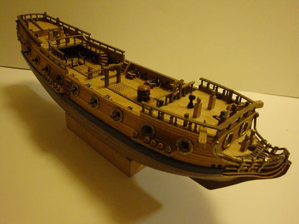
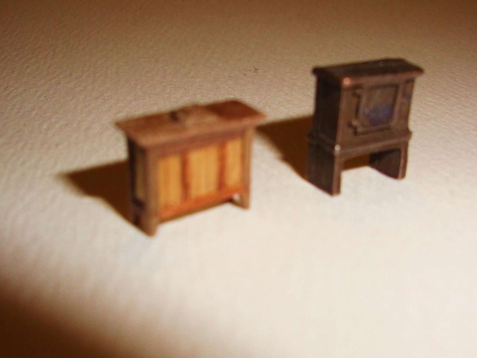
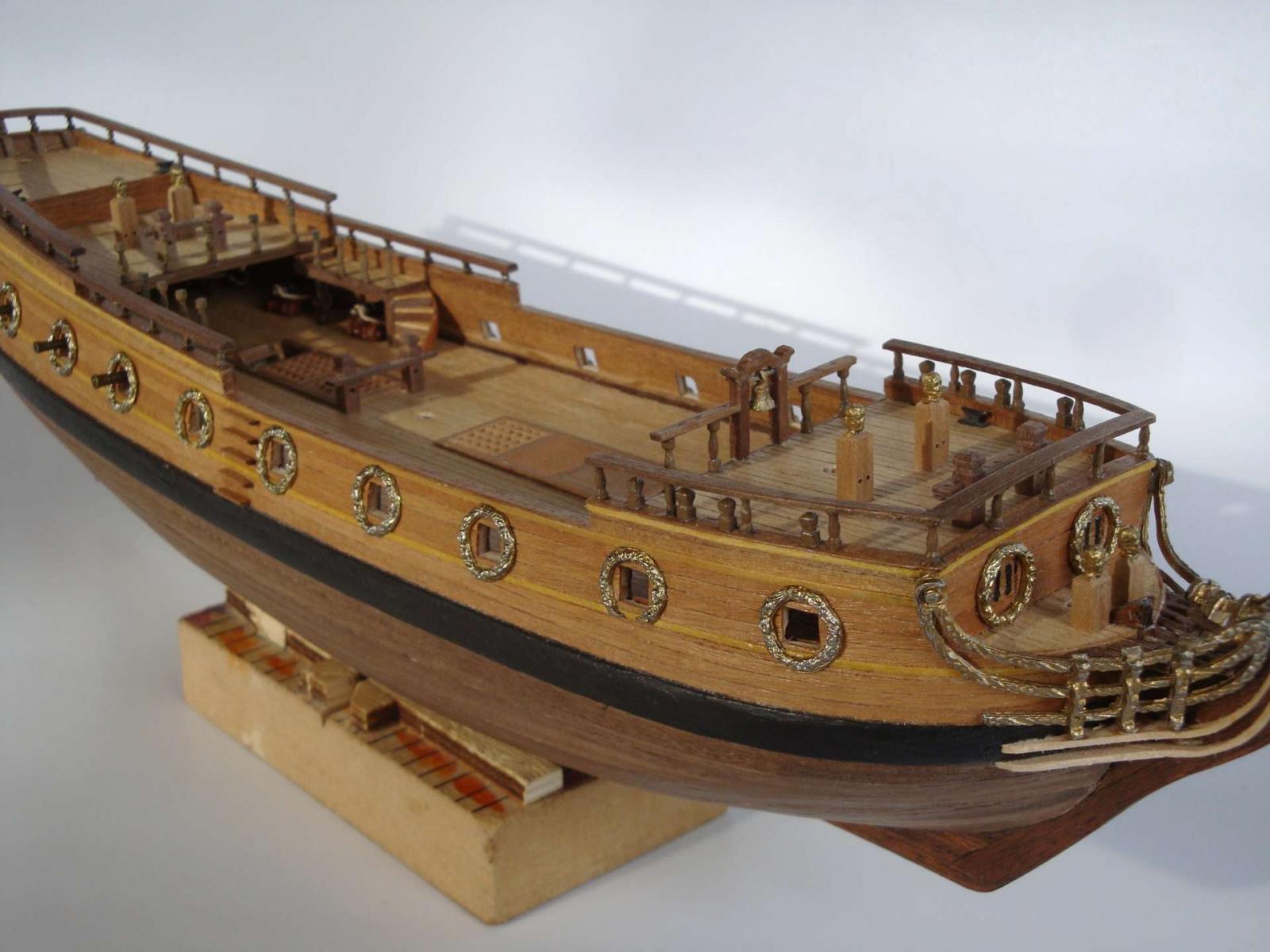
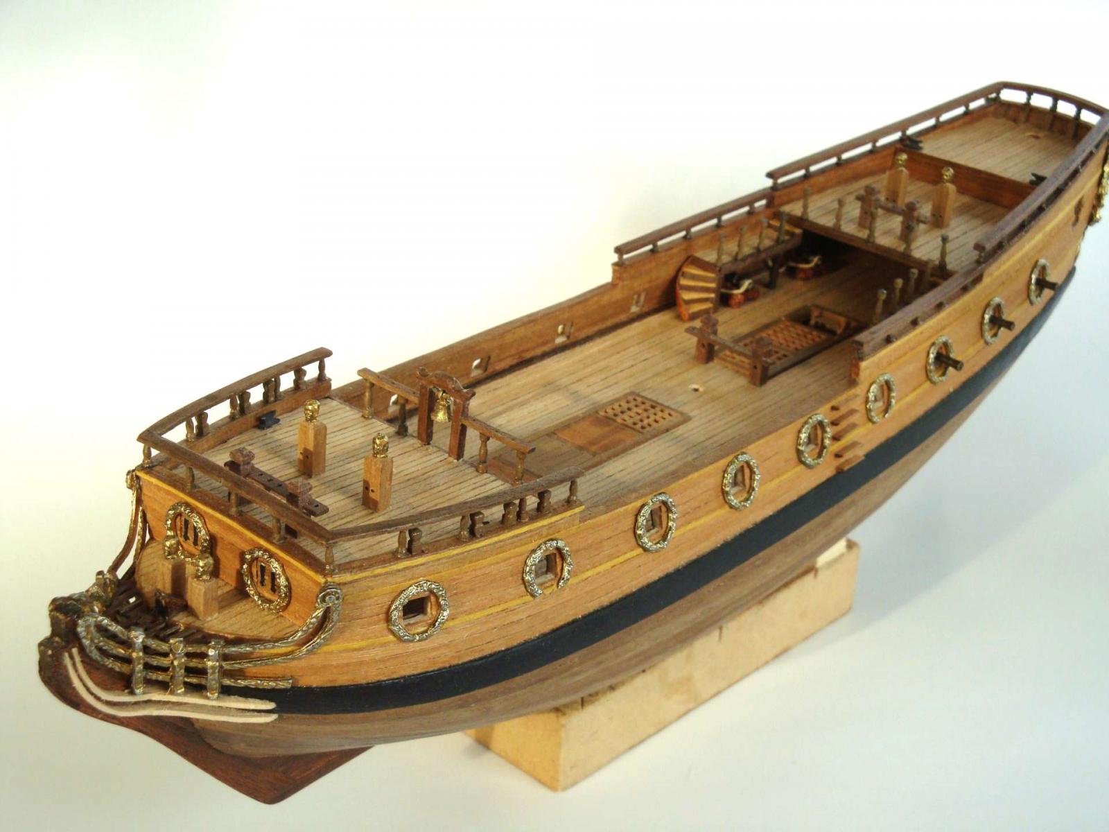
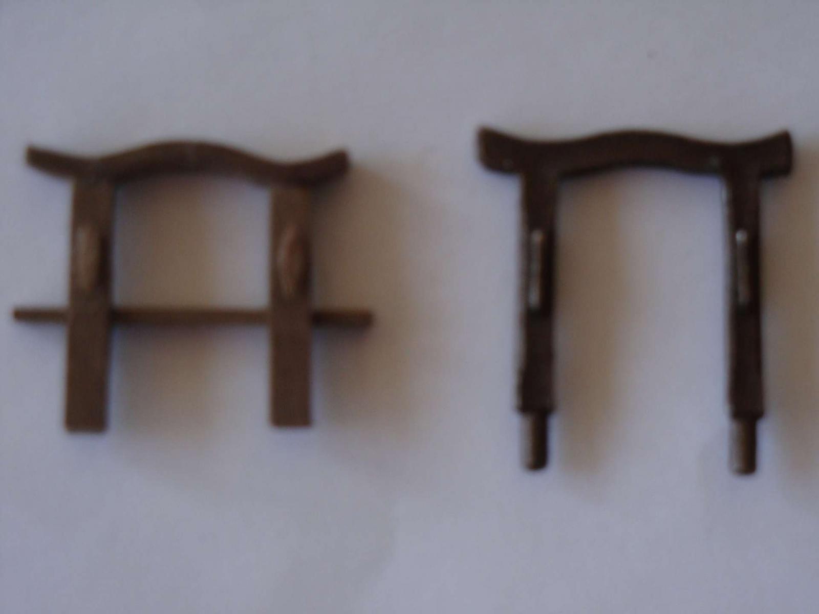
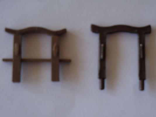
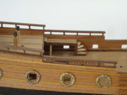
The kit provide a mixture of good and out of scale metal casting components, At times it would be best to repace those out of scale ones with new scratch built one matching the drawing plan .Since the ship itself is small. Any scrap wood would do. The kit provided molded rail post castings are pretty good and matched the drawing plan very well. They are also very hard to duplicated in wood, so I used those. Other components should be replaced are: the binnacle (the kit's looks iike a bended oven), The bitts (the kit's is too small) The knight head is a hyid. the kit provided - head portion is fine, but the stock is too skinny. Cut of the head and reinserted/glued with correct sized wood stock. Sorry for the pictures being out of sequences. I can't figure out how the uploader re-arranges them.


-
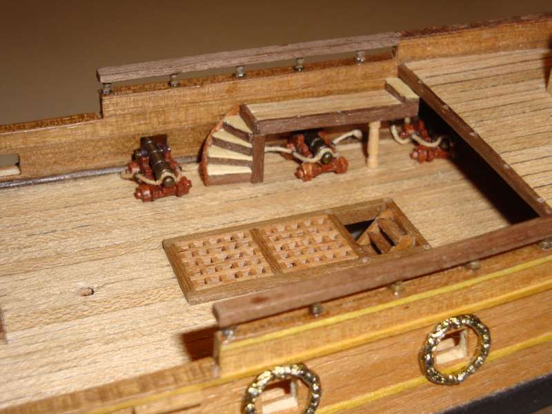
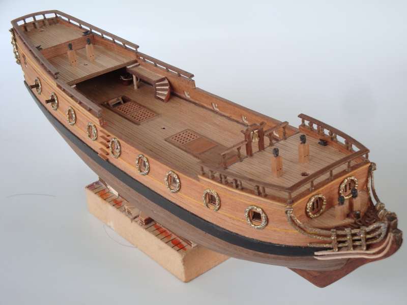
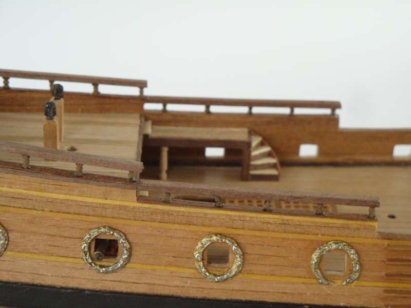
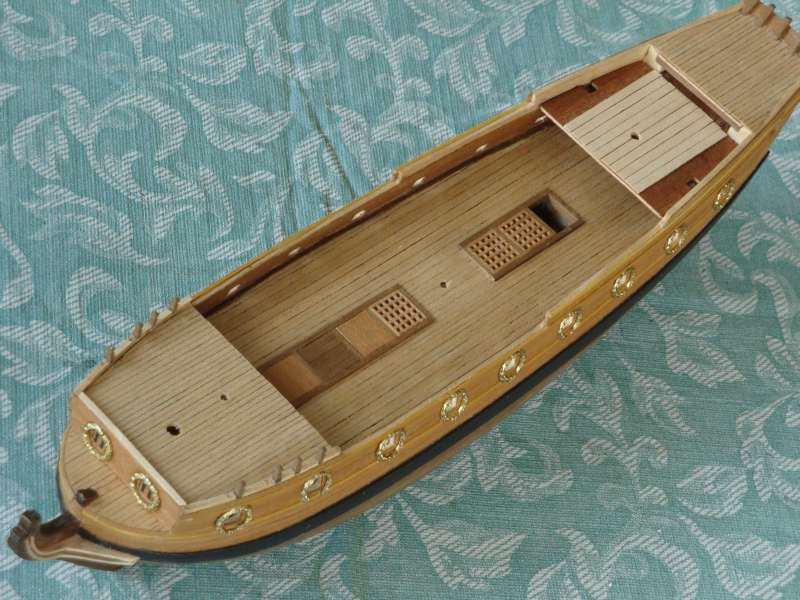
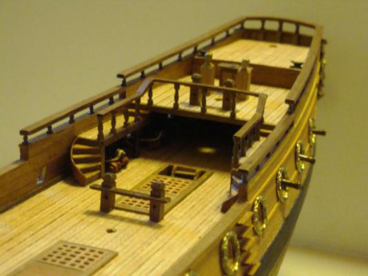
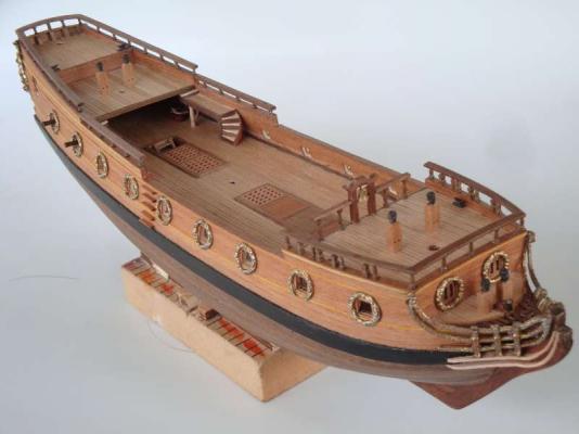
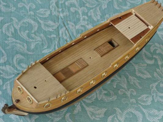
The spiral stair case located midship is a pronunced feature on this ship. The kit provides a metallic molded stair case, it is out of scale and not suitable. scratch build your own, The key point to remember is the stair case center post is "square" not round as research showed. This also make the construction easier, Th other thing to space out the correct number of stair threads matches the drawing (this will assist with height spacing of each stair step). Glue the stair case outter rim to the first stair case thread (see picture 5884). This will form the quarter circuie shape of the stair case, Once dried, add the remaining stair raiser, then the step thread plate to complete.
-
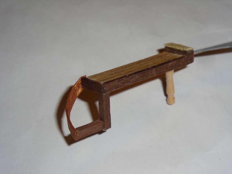
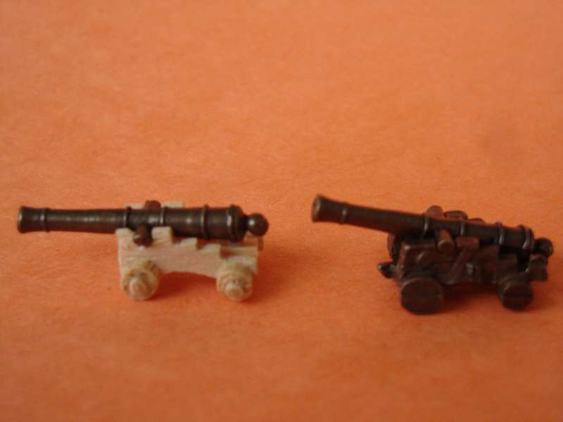
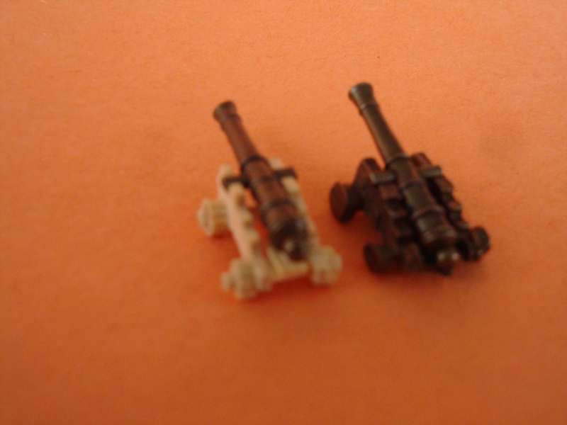
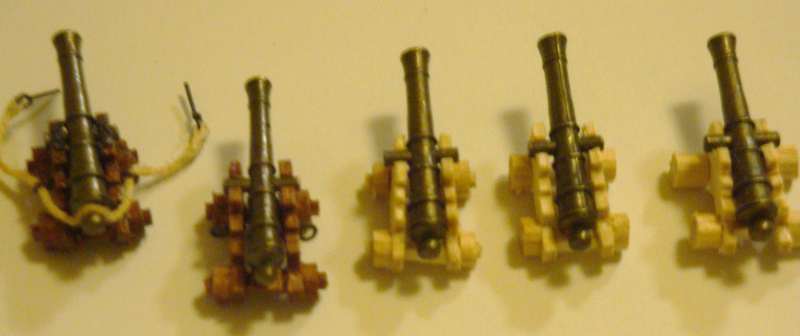
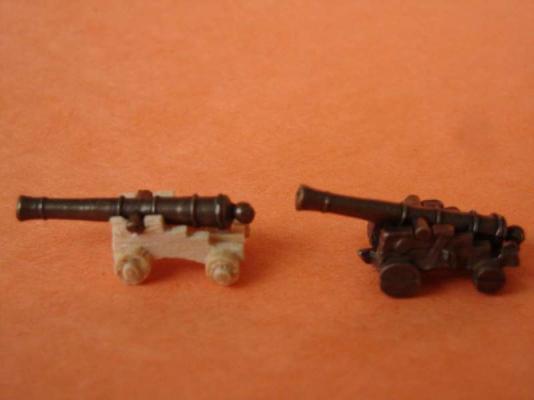
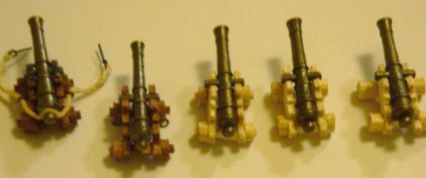
Build pics 3 Comment update 1/1/2014 The kit's provided molded gun carriage has nice details and portion, However, it isn't correct for this kit. The carriage is too wide and not the right scale. As a result, the gun barrel sits too far back in the carriage (see comparison pictures 5836 and 5837). It is best to replace those with the correct sized wooden gun carriage. Use the drawing plan as the guide for the carriage size. Note: The gun barrel matched the drawing well. The wood carriage also enables the gun trackler ring and rope to be installed which with the metal carriage will be difficult. Picture 5874 shows the different built stages of the gun carriages. Warning: Be PATIENT, this will take a while and boring. Howver, you will be glad you did afterward. It does make a big difference in the finish model.

-
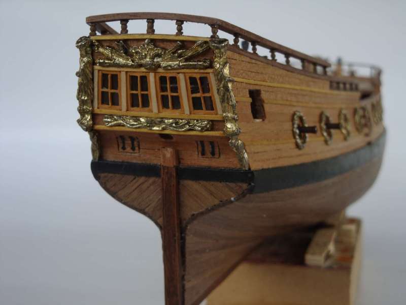
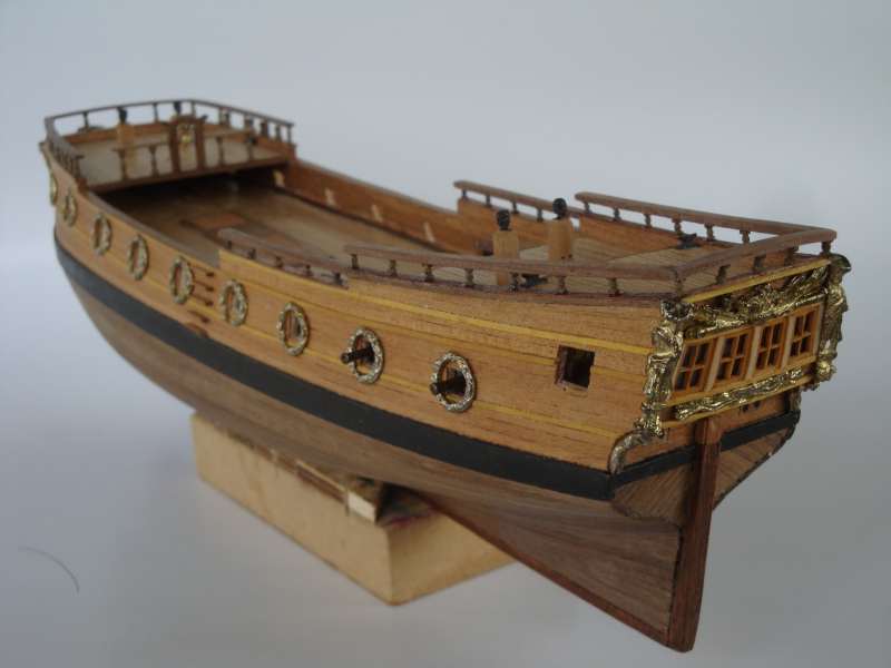
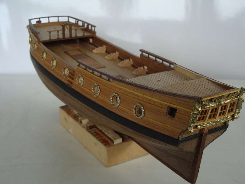
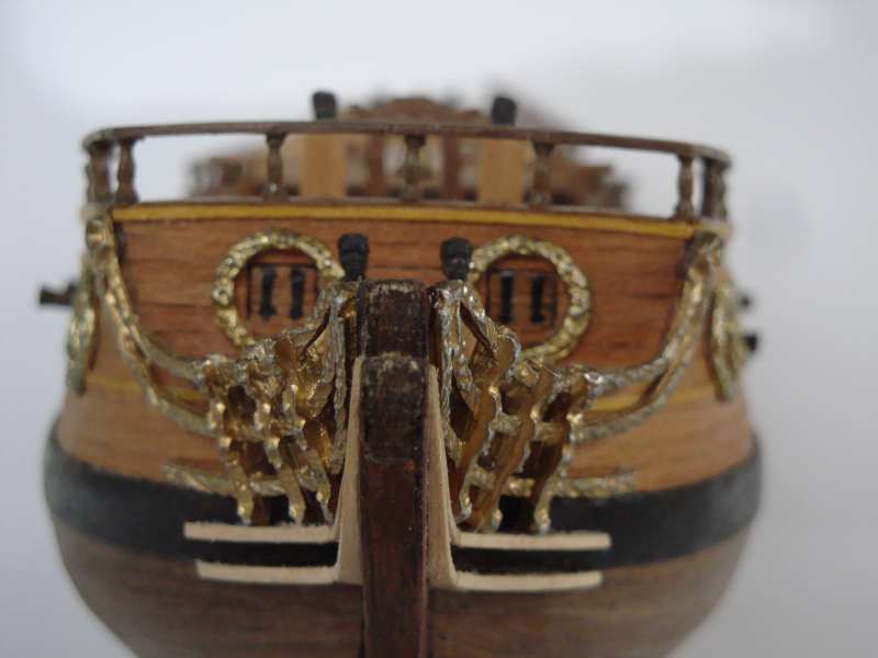
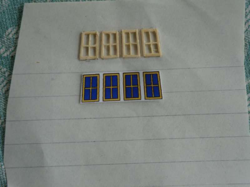
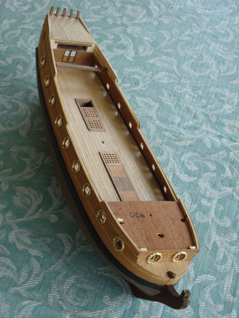
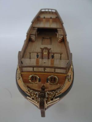
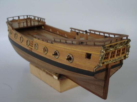
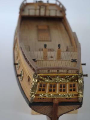
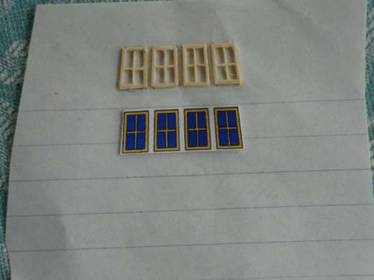
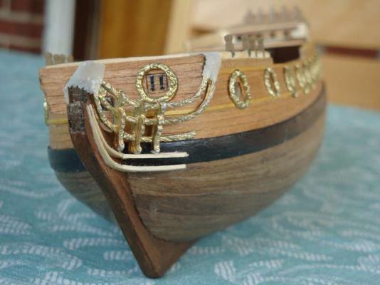
Picture 5282 shows the comparison between the scratch window frame versus the paper printed window image. The paper printed window represents only two demension and should be replace with a 3 demensional window. Trace the window outline onto a blank paper. Glue the correct sized wood stocks to the paper. Once glue dries, use a sharp blade and cut the completed wooden window frame away from the paper. sand away any remaining paper on the window frame (use a fine grid sand paper).


-
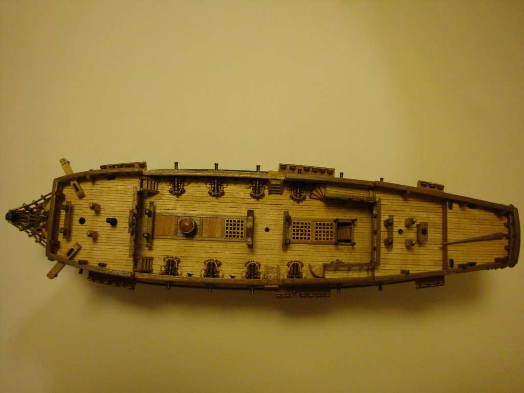
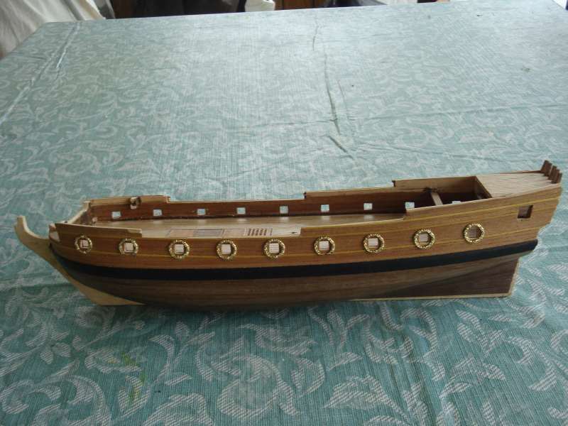
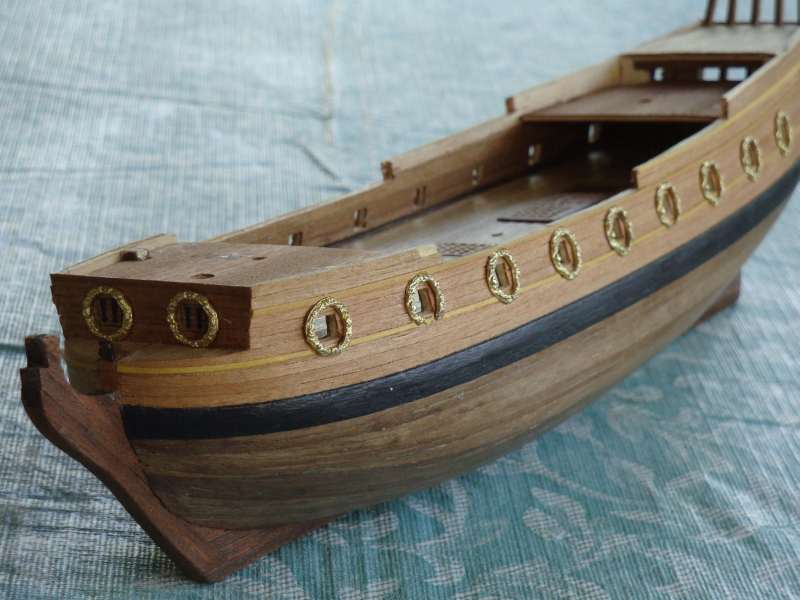
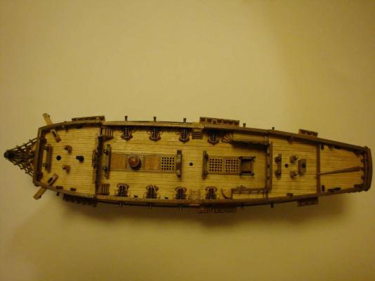
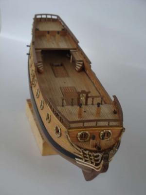
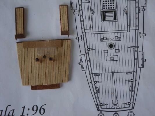
The key to making this ship model is to use the drawing as the primary reference for the build (the supplied components are not to scale nor correct at times). If it does not resembles the drawing, make your own replacement part (there are small enough, any scrap wood laiding around will do). Picture 5194 shows the kit provided deck planking (lighter color ones) in comparison to the rest of the deck with the planking split in half with a #11 blade. Pencil was utilized to simulate culking between deck plankings. VERY IMPORTANT: Cut the lower portion of the second gun port ring (see picture 5115, use the drawing plan as the reference), This is required, as the channel will be in the way it is not done, I have seems a couple of built of this model recently, Most did not trim the 2nd gun ring. As result, the hull and the stern profile ended up taller than it should be (also the sequential gun ports' height), The stern window, the stern decornation will not match up.


-
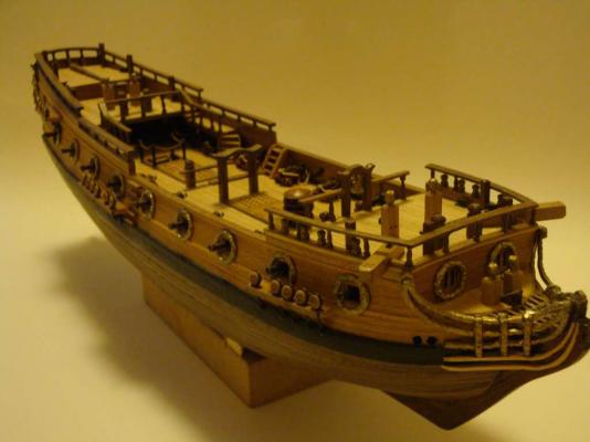
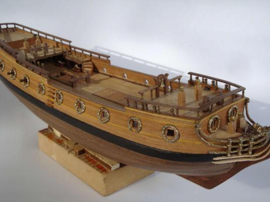
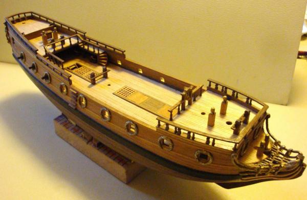
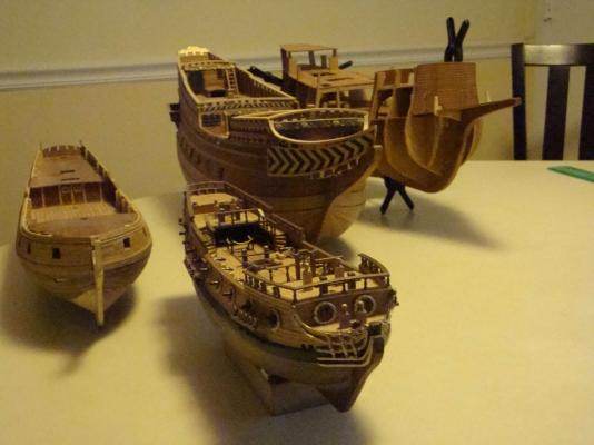
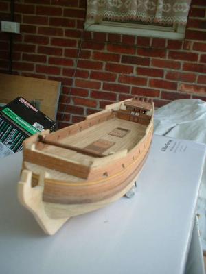
I had a build log of the HMS Peregrine in the original site, but when 2.0 web site launched, it was lost for some reason, I will re-post some of the buiidling progression pictures from the previous log and restart the build log again as some member expressed interest to see the build log again, Another compelling reason is there isn't any active building log /coverage on this particular ship/kit. looks like pictures were lost again.. reposting (4/11/2014)
-
There seems to be an mis-identity issu resulted from one of my reply to the build log owner "TheCommodore". I had a build log of the HMS Peregrine in the original site, but when 2.0 web site launched, it was lost for some reason. If there are interests out there (let me know),,, I will start the build log again. I don't want to hi-jack "TheCommodore;s" build log. To: ZyXuz- yes, it is very small, but also very challenging..