HOLIDAY DONATION DRIVE - SUPPORT MSW - DO YOUR PART TO KEEP THIS GREAT FORUM GOING! (Only 13 donations so far - C'mon guys!)
×


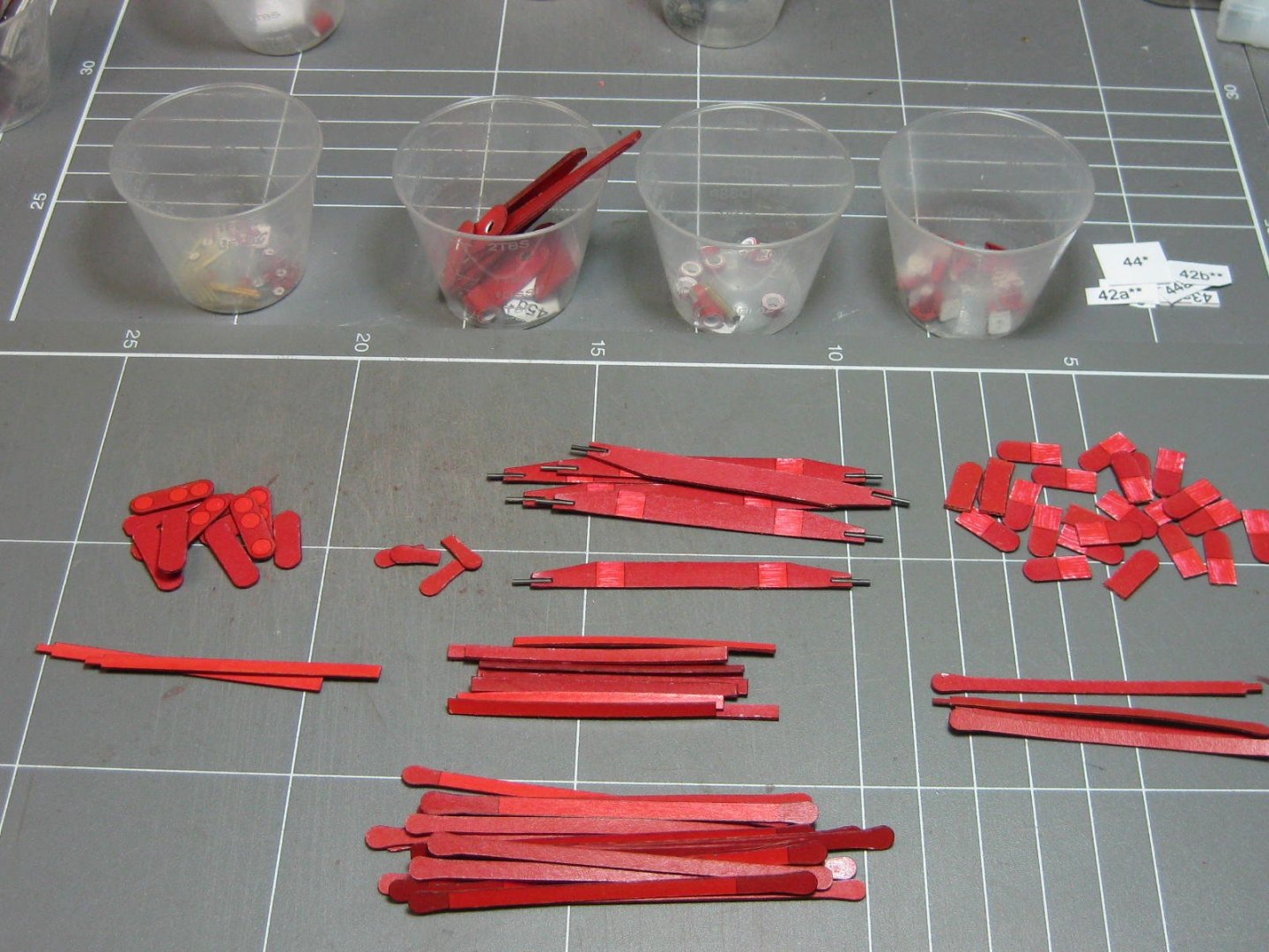
Dan Vadas
-
Posts
3,261 -
Joined
-
Last visited
Content Type
Profiles
Forums
Gallery
Events
Everything posted by Dan Vadas
-
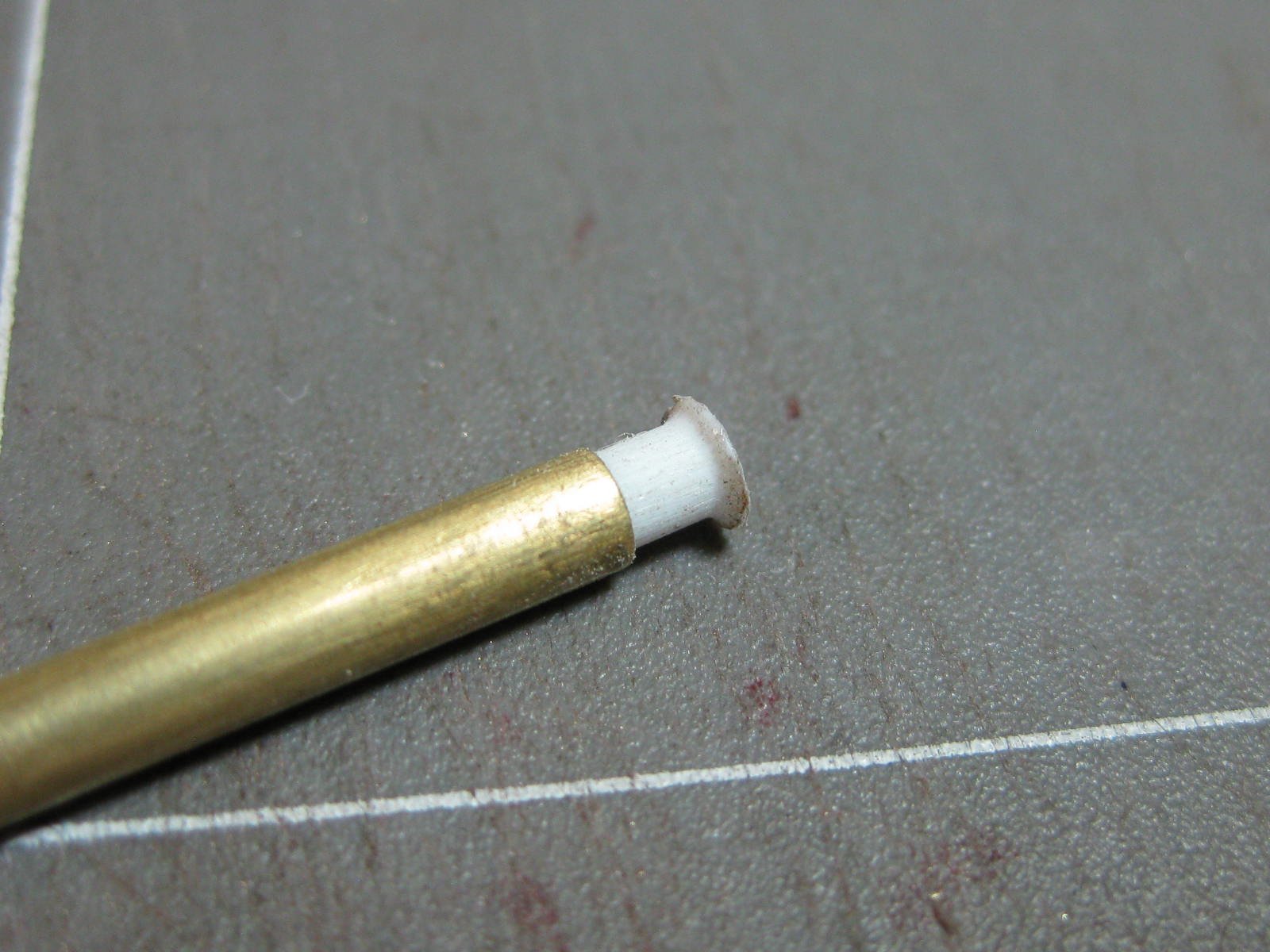
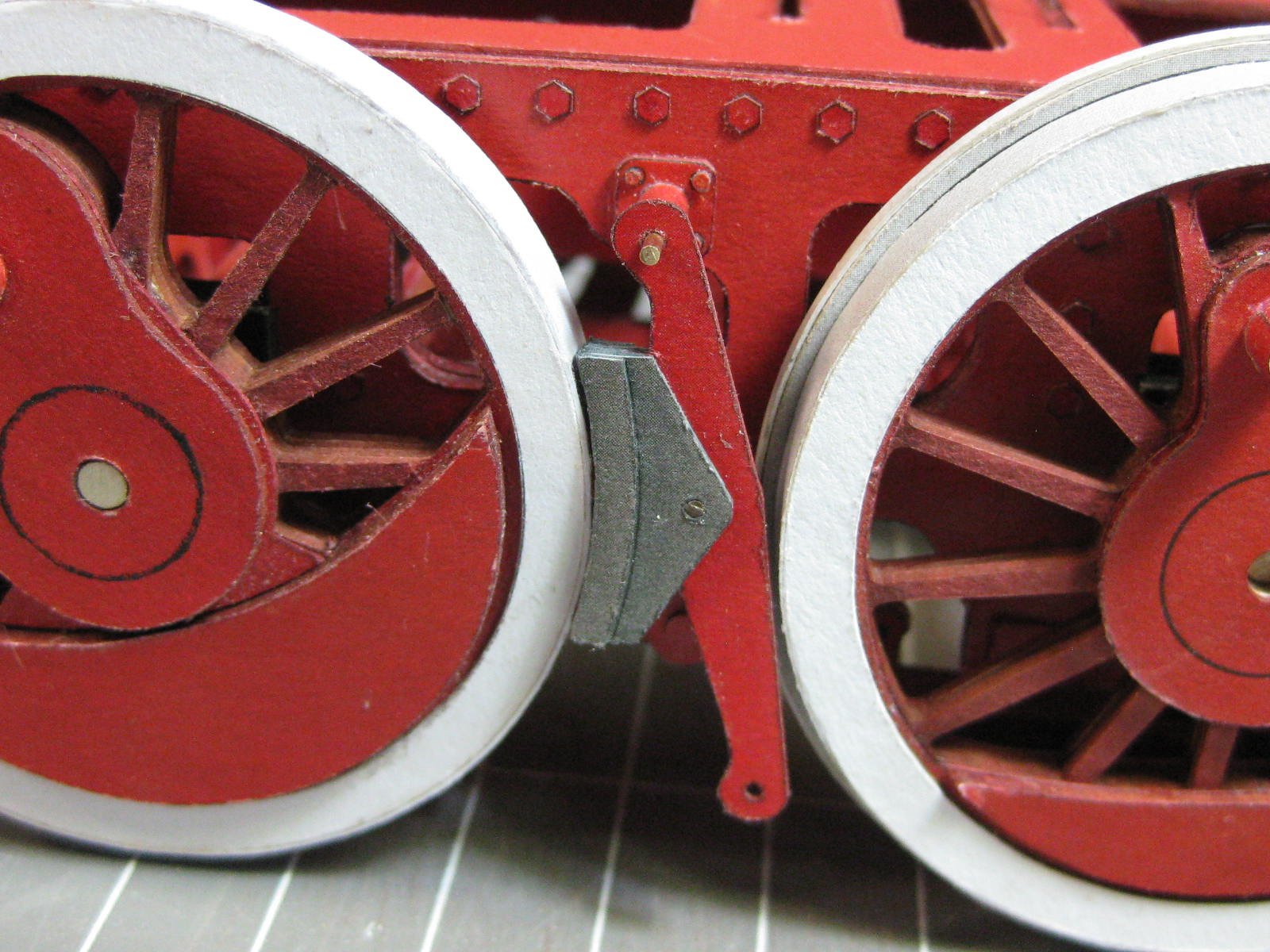
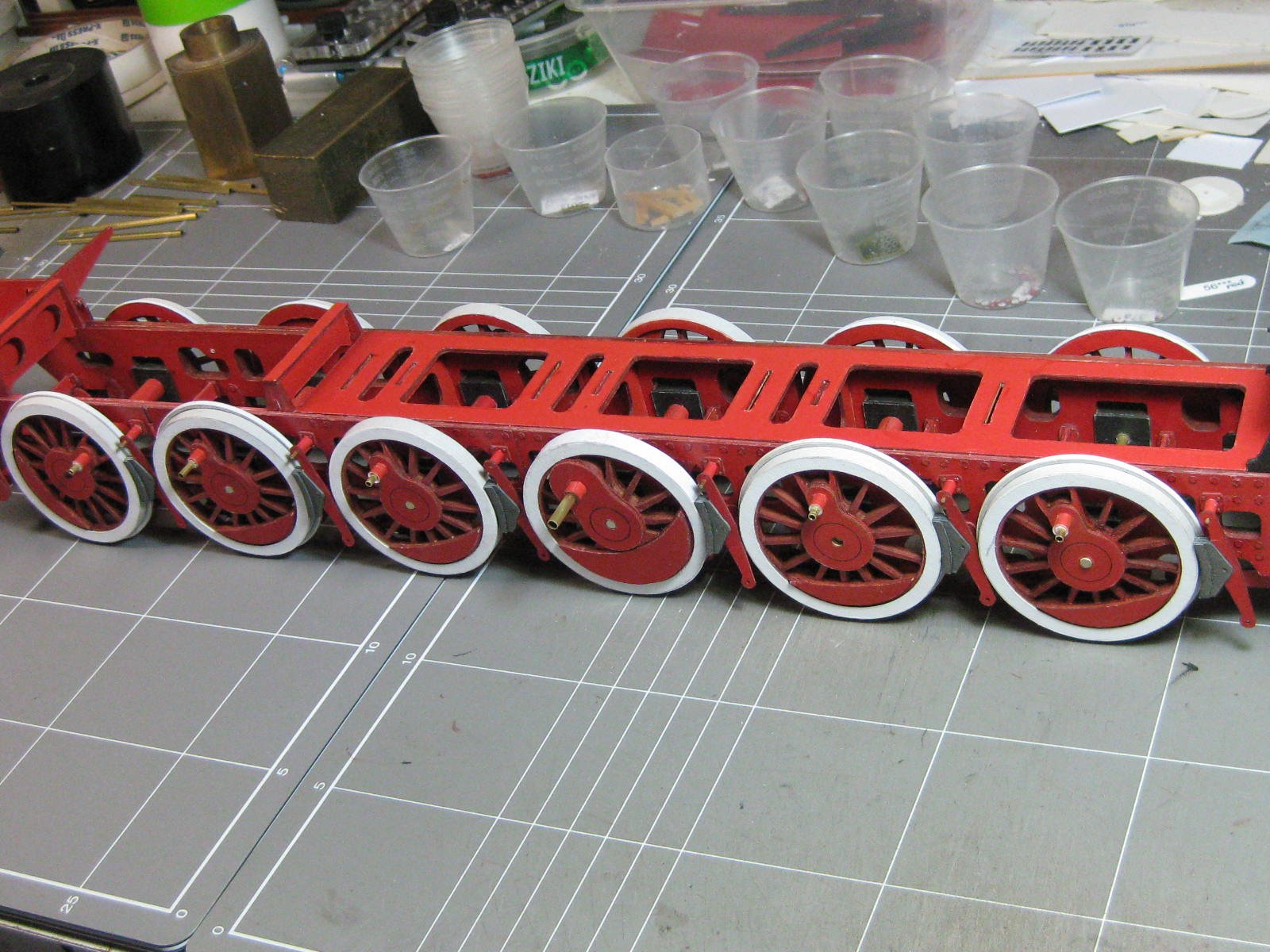
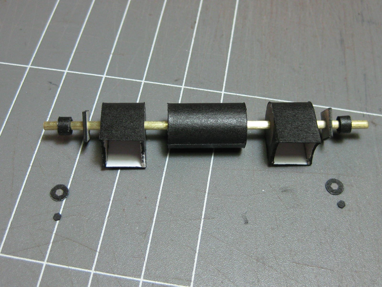
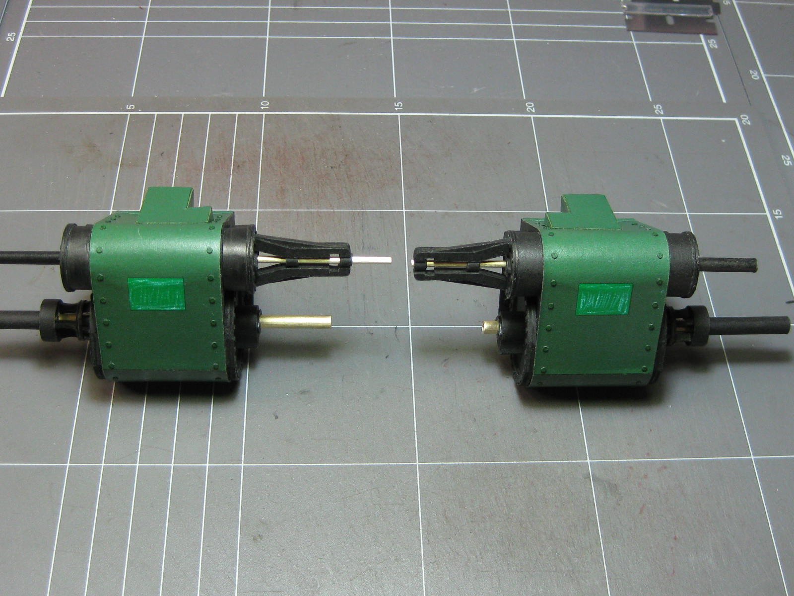
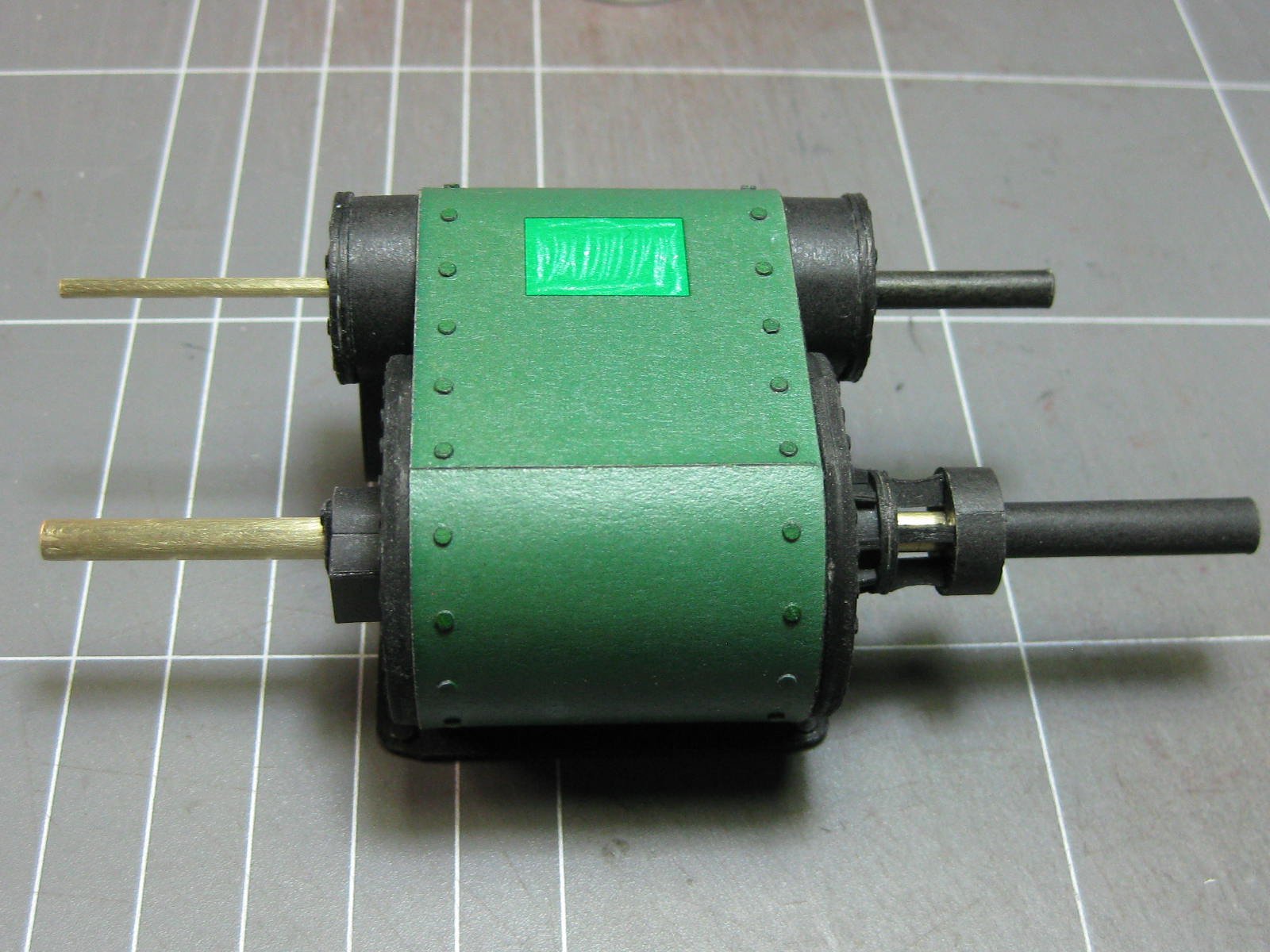
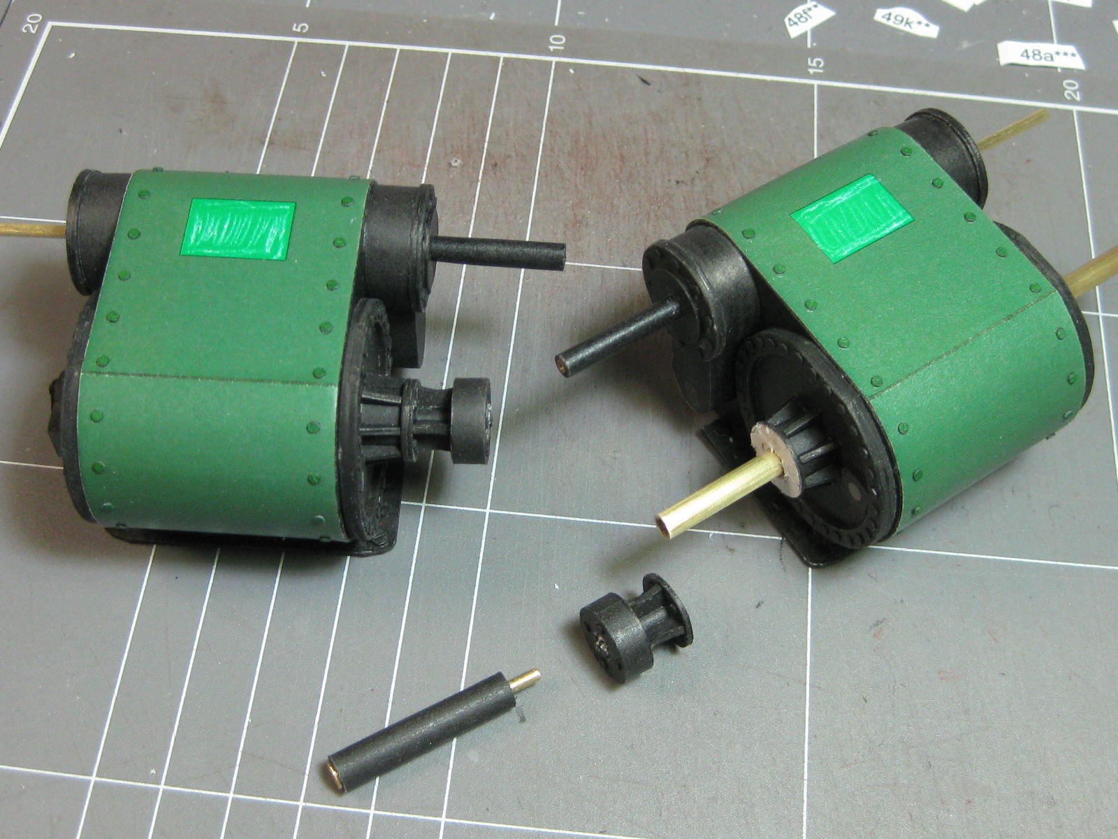
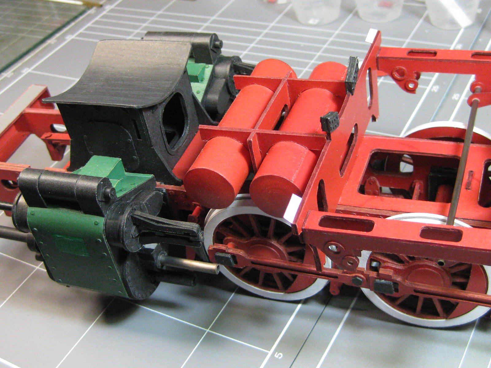
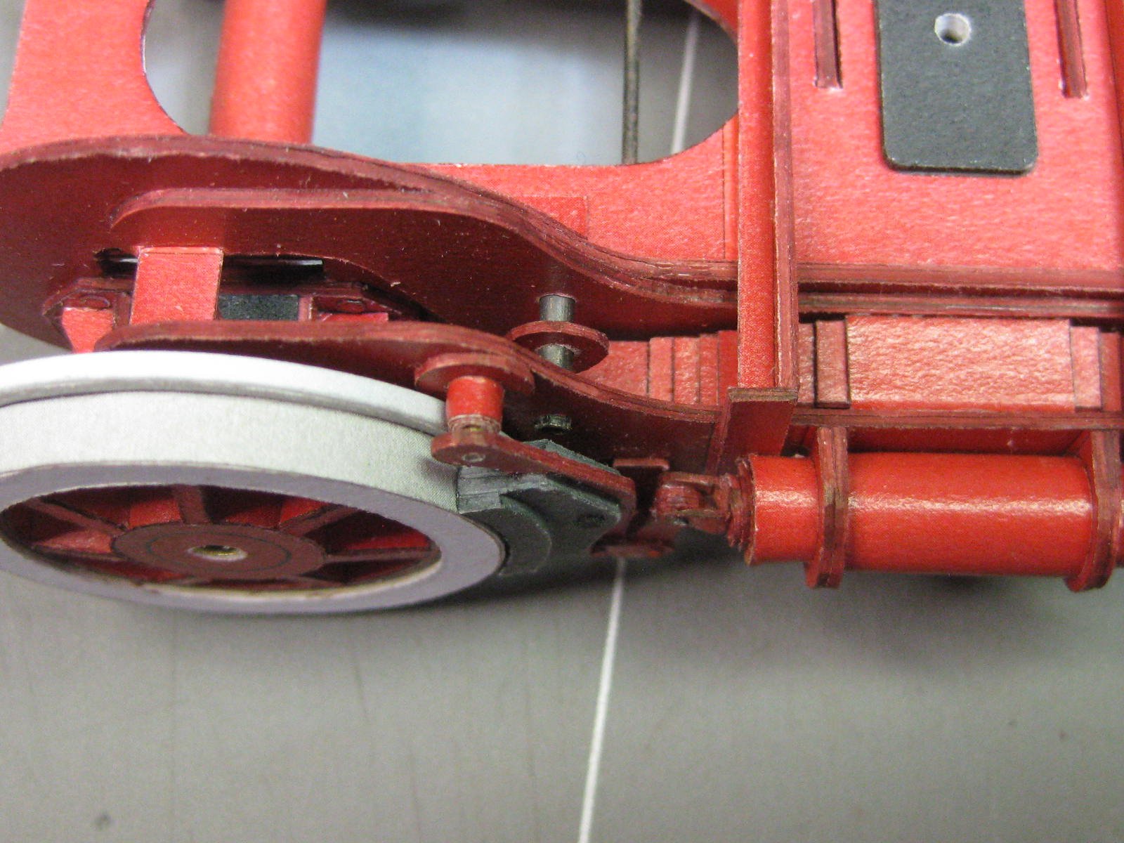
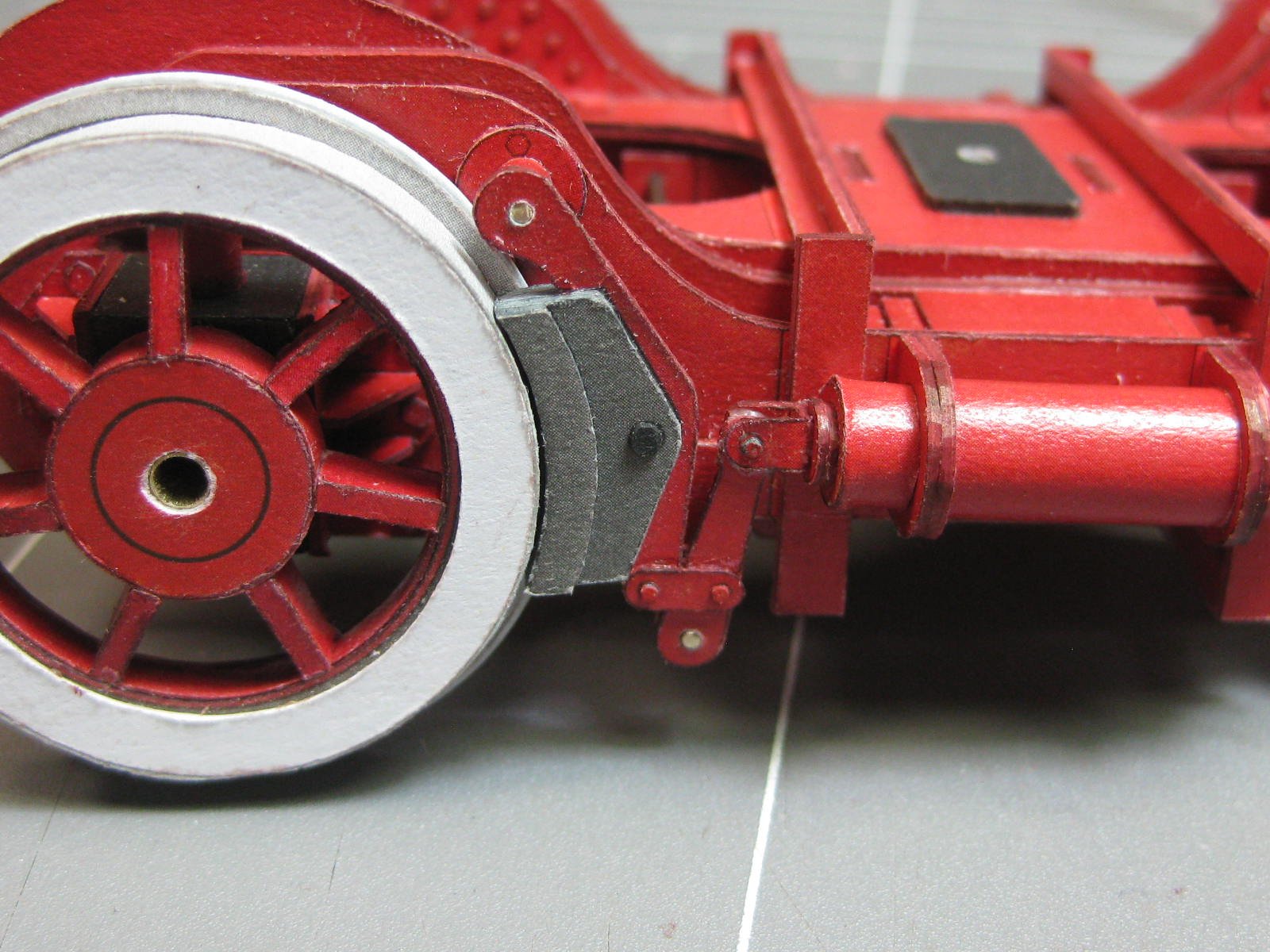
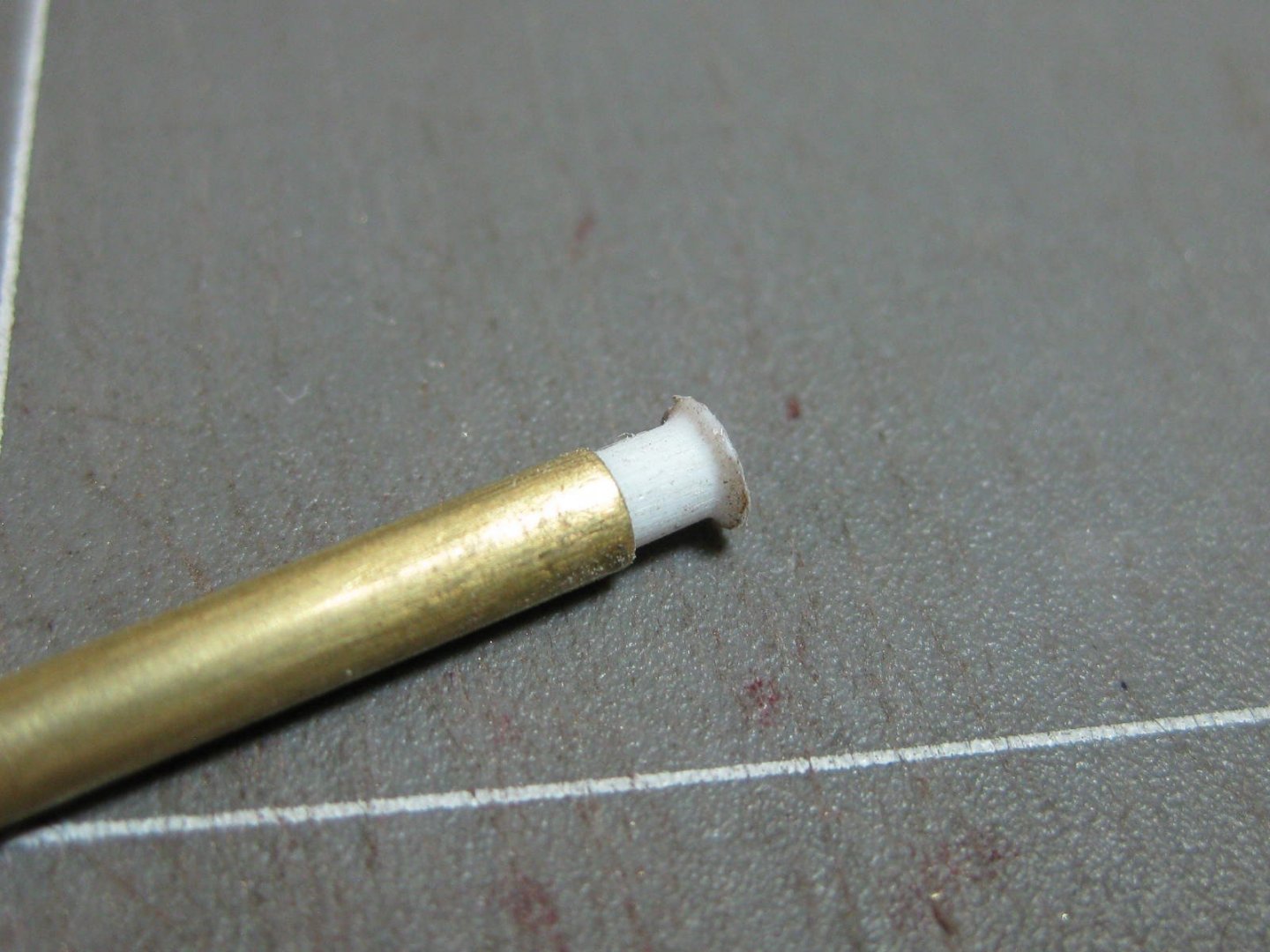
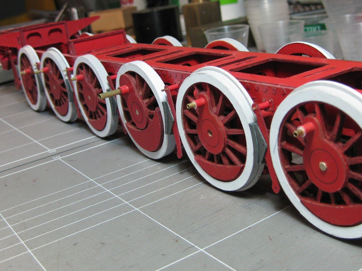
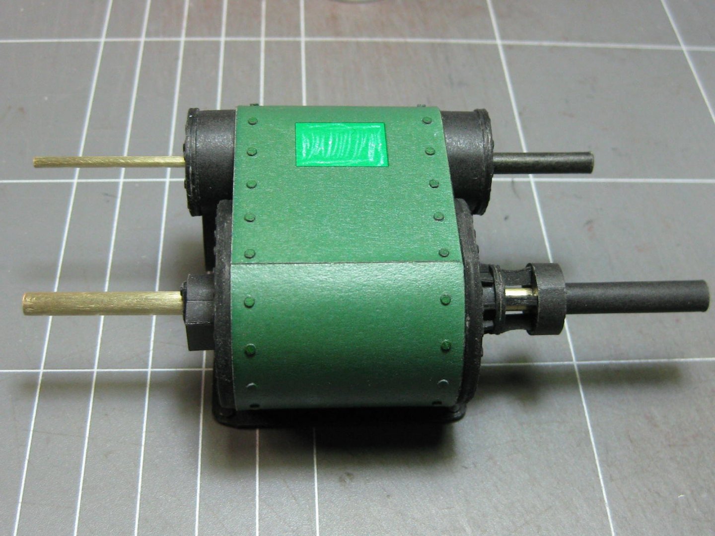
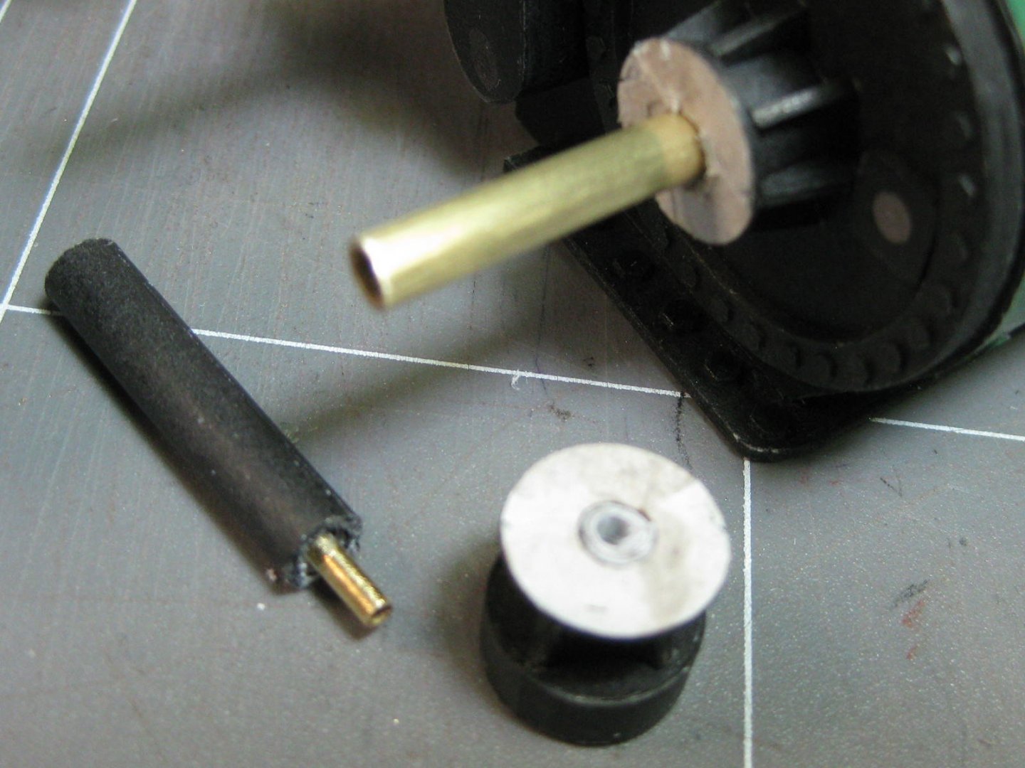
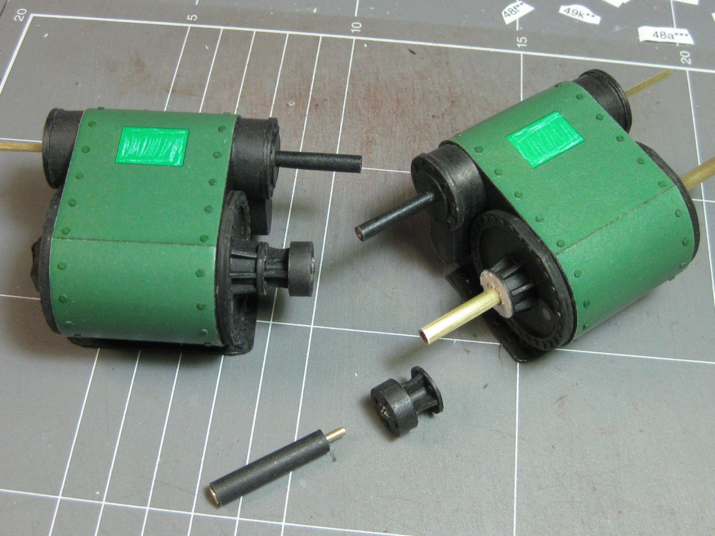
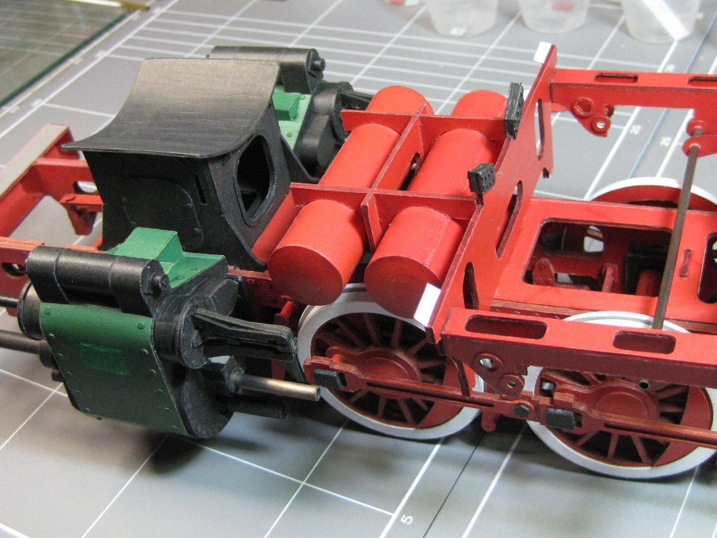
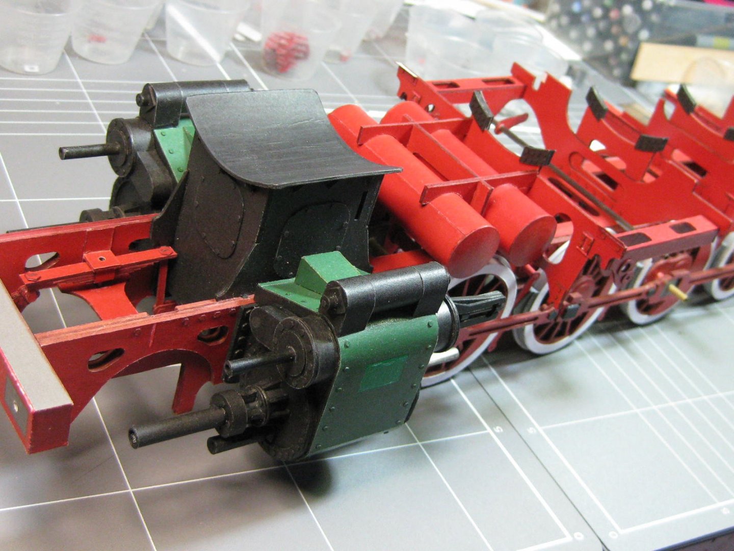
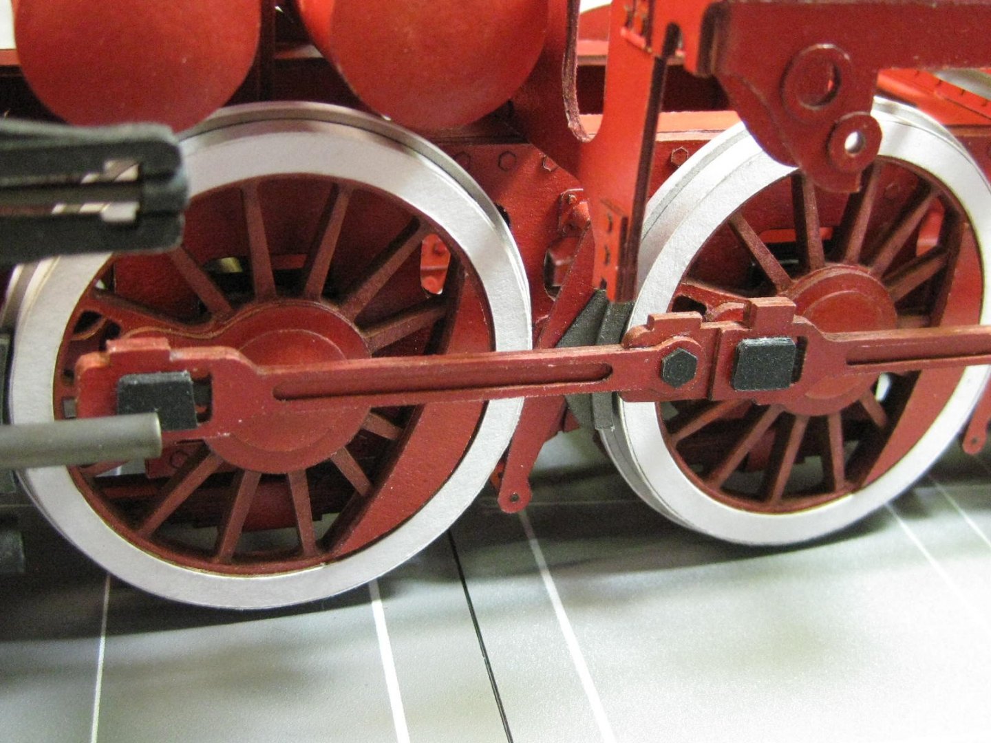
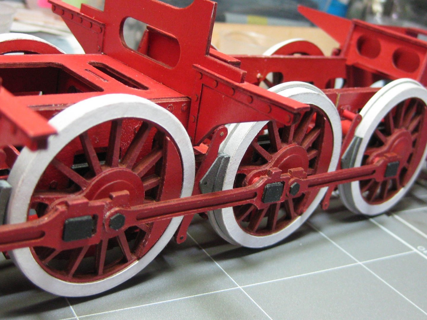
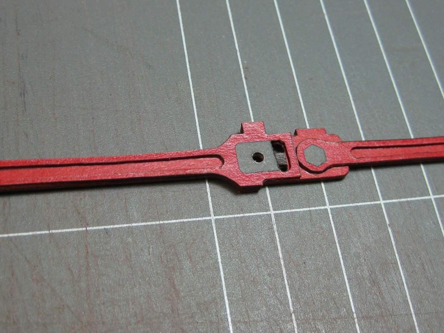
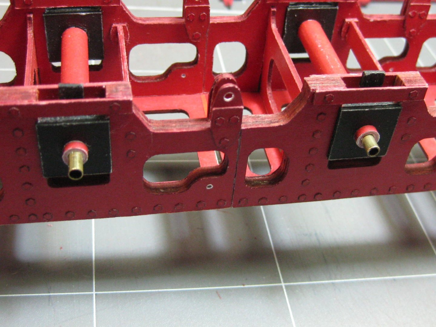
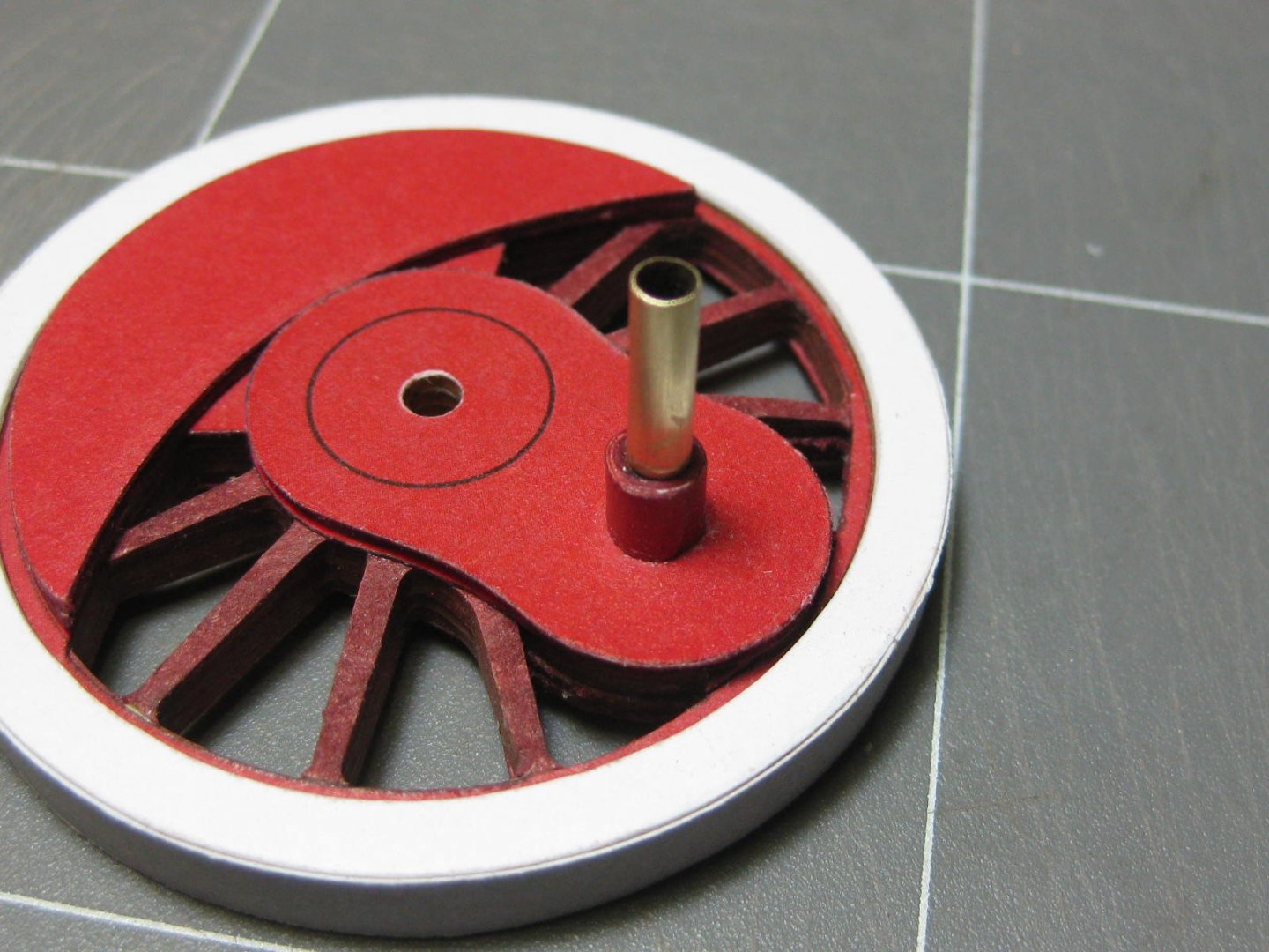
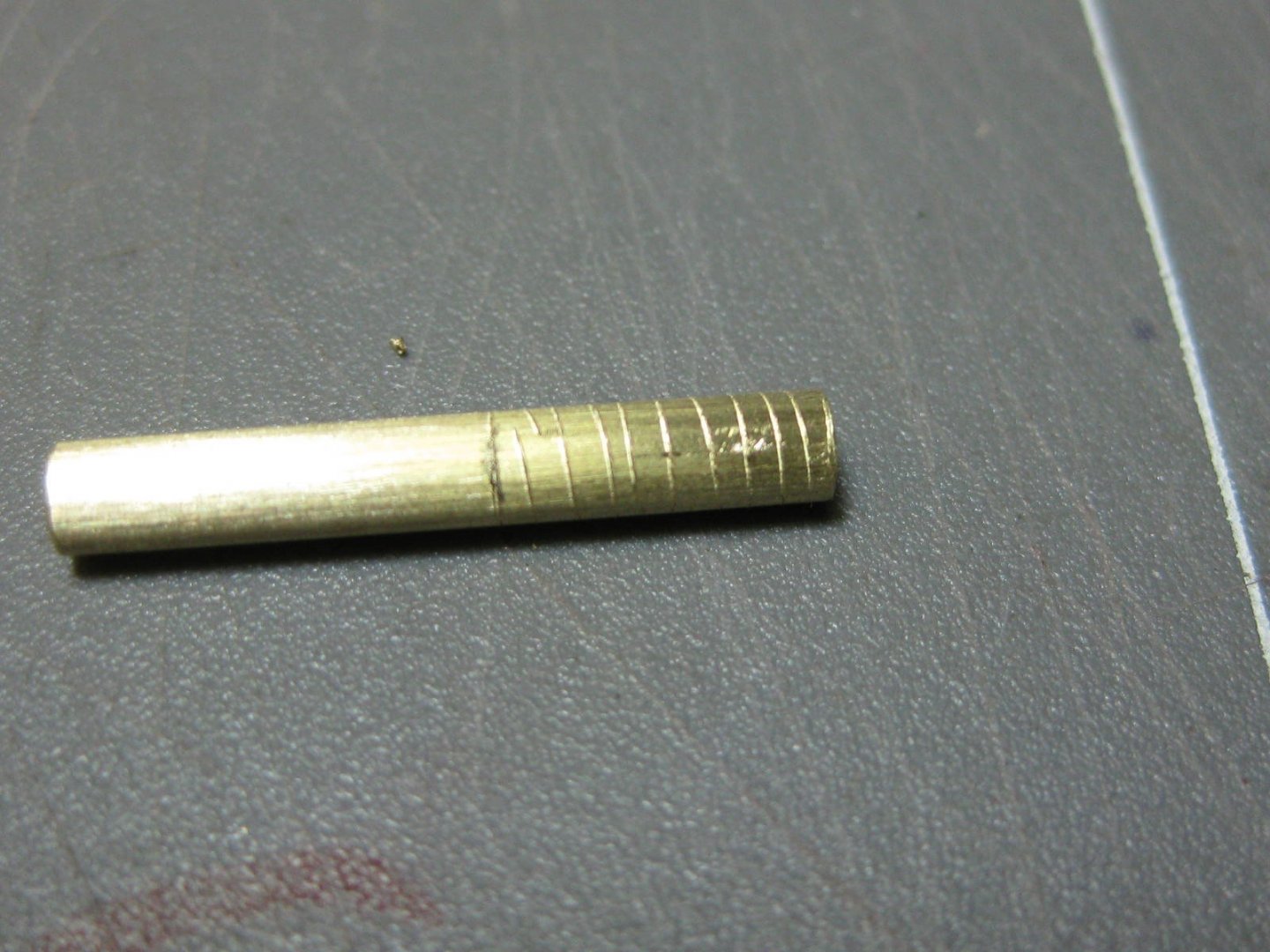
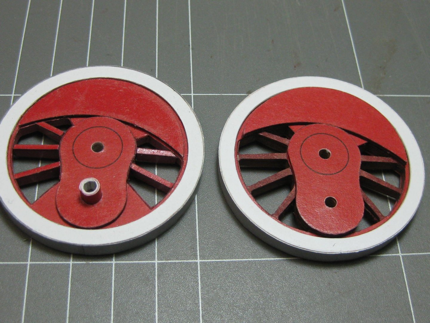
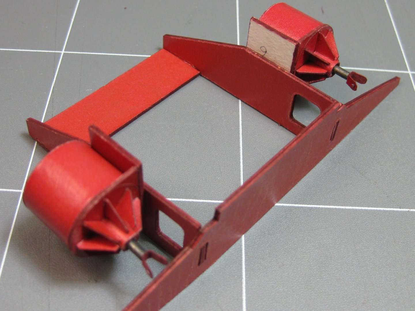
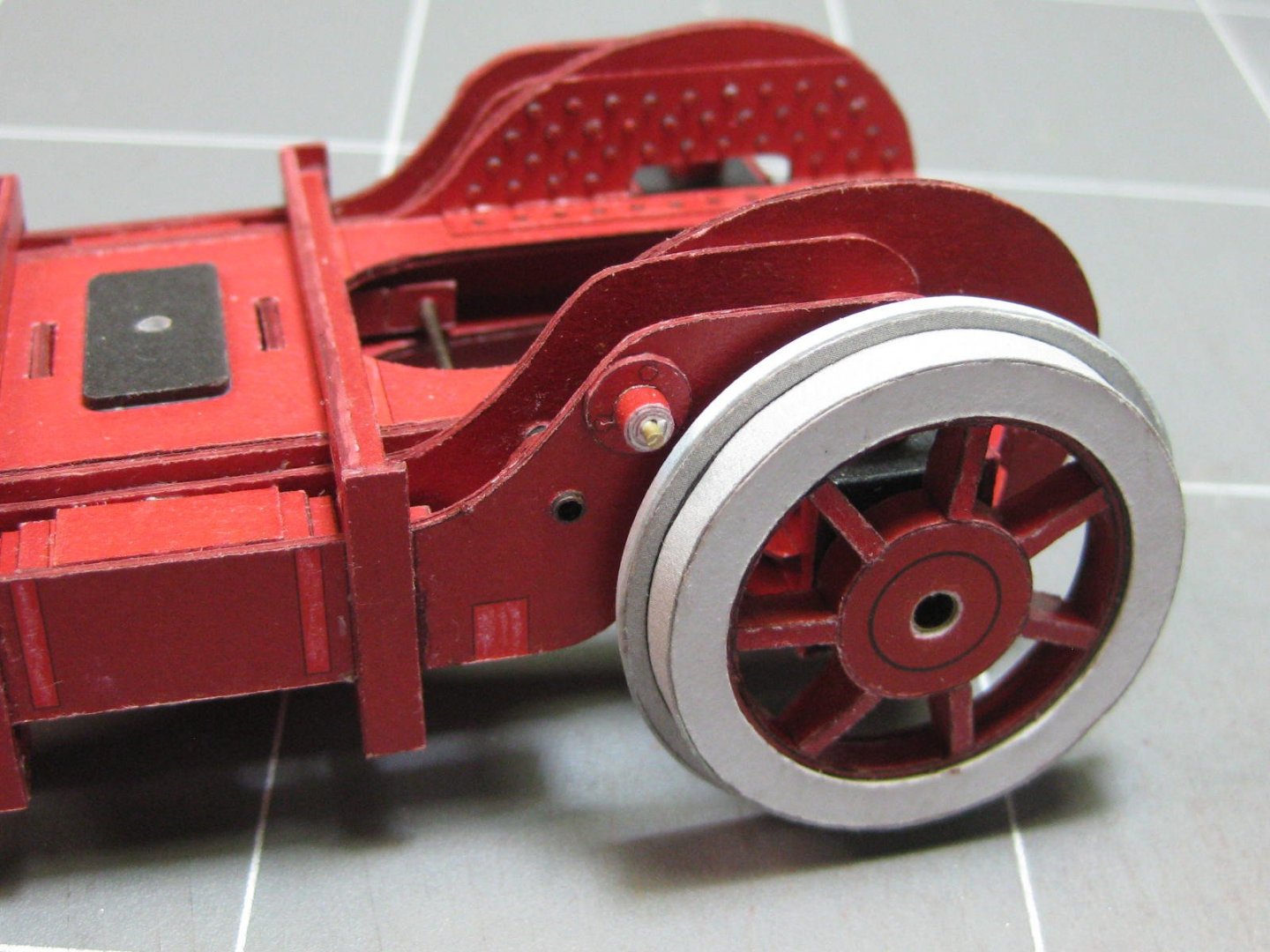
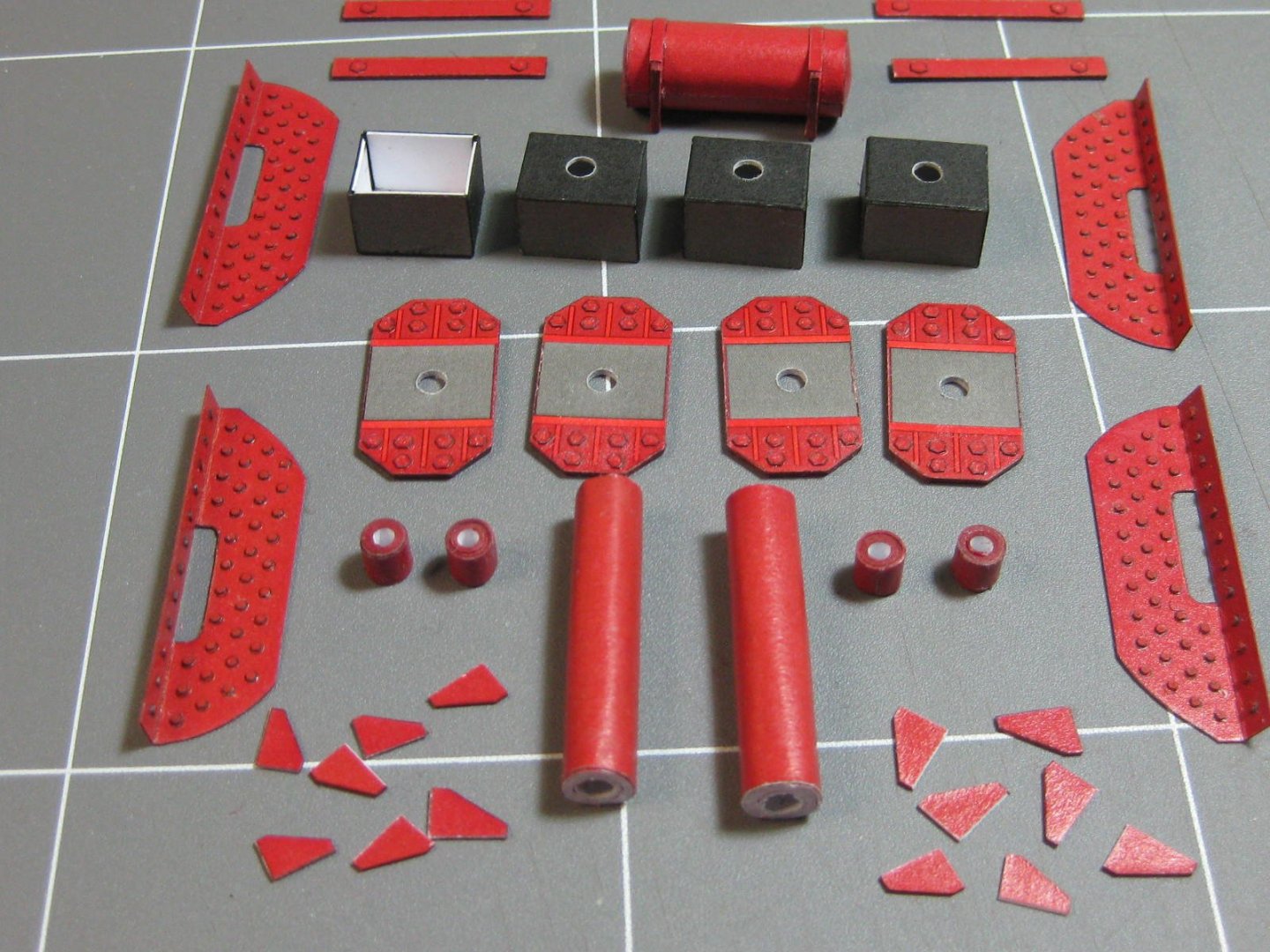
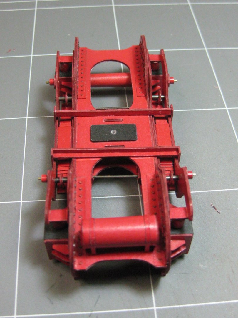
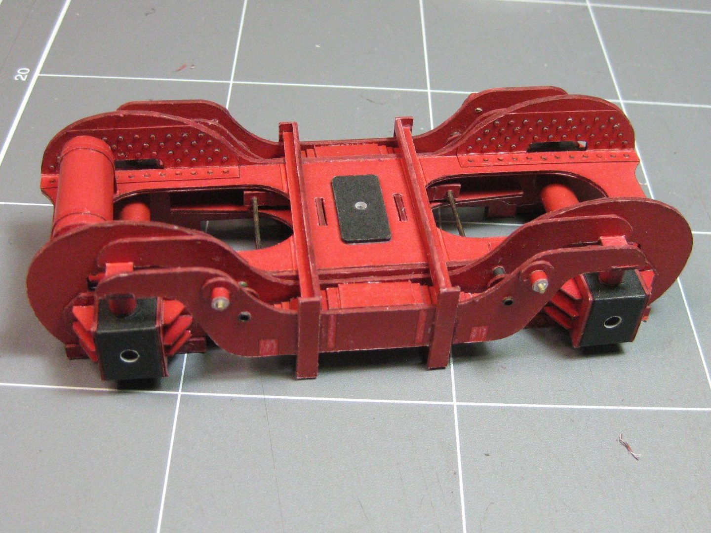
Thank you all for the Likes and comments. These are one thing that is keeping me going with this build - another is that I'm thoroughly enjoying it . The two compressed air tanks. The ends are slightly domed. I cut some scrap paper roughly to shape to prevent any crushing later. The skin is only glued along it's edge : I've fitted all the main wheels and finished the brake mechanism for them. The brake shoes needed a little sanding to bed them in properly : To hold the wheels into the tube axles I mushroomed the ends of some tight fitting styrene rod with a small soldering iron and filed them as flat as possible : The drive axle needs to be a solid fit as the two wheels have to turn in synchronisation. The crank pins are offset by 90 degrees from each other so that one wheel is vertical while the other is horizontal. This keeps the drive going without any stopping. To make sure they don't slip on the axle I made a keyway for each and also used CA glue to hold them to the axle : Danny


- 150 replies
-
- 15
-

-
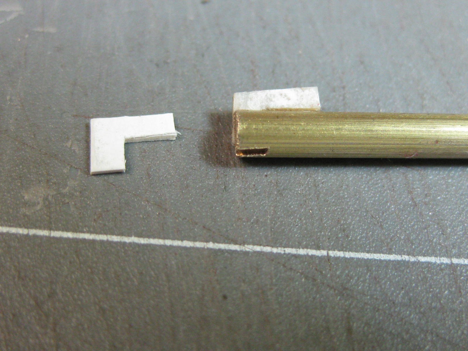
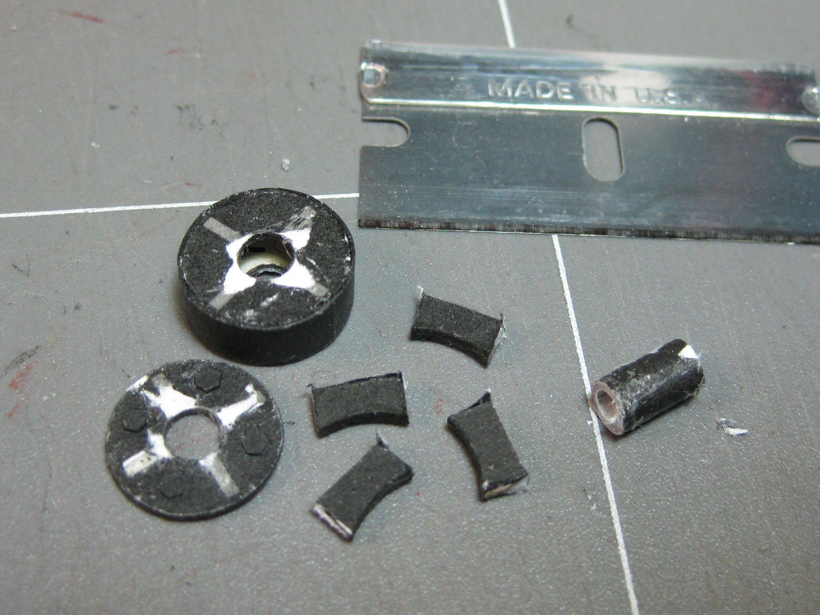
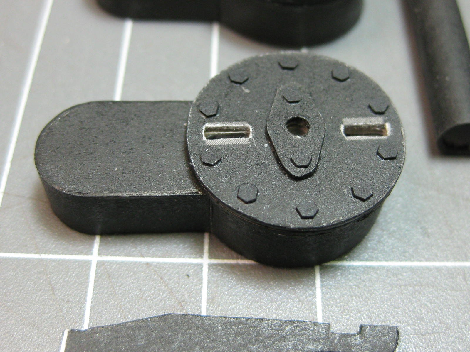
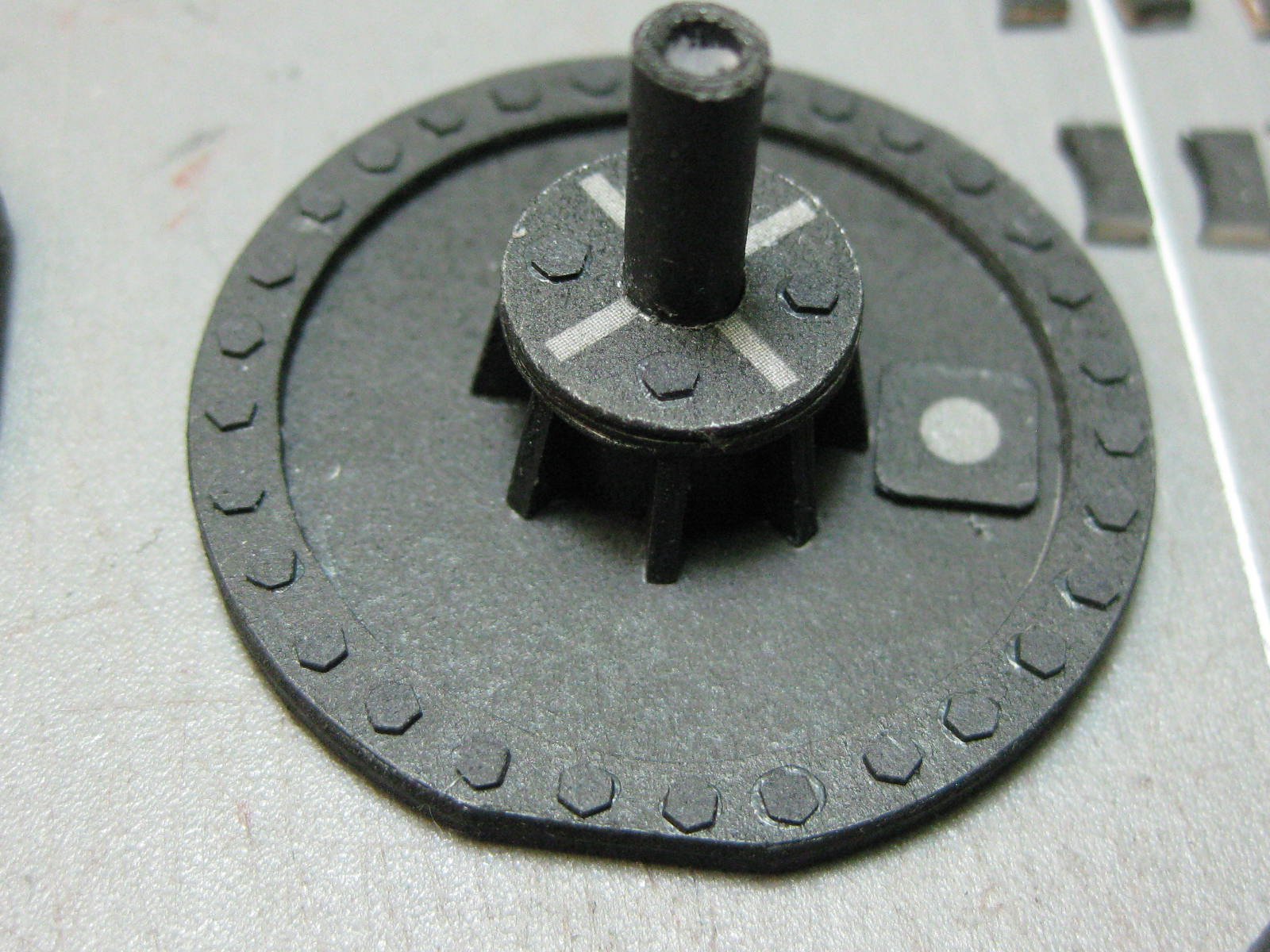
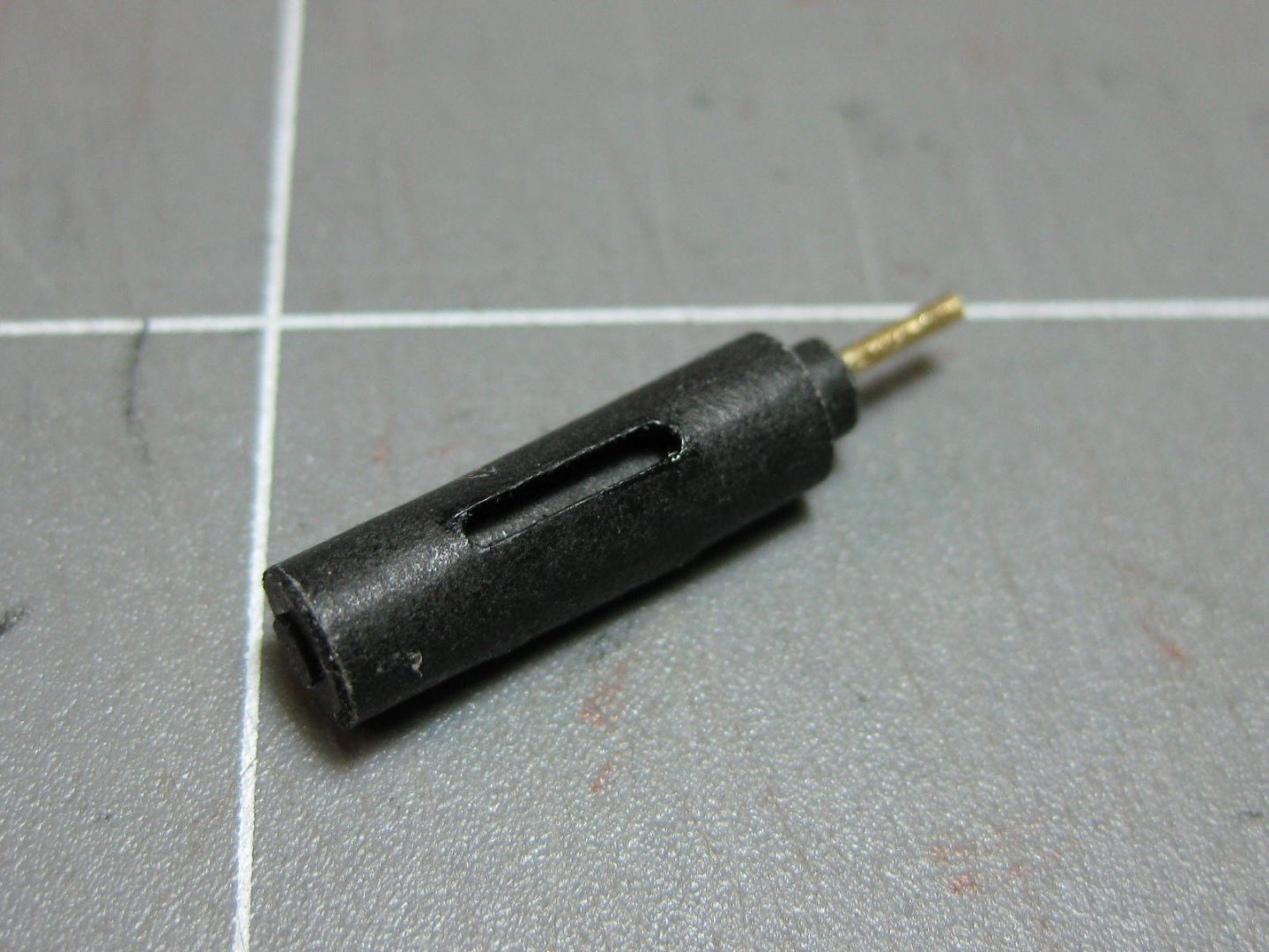
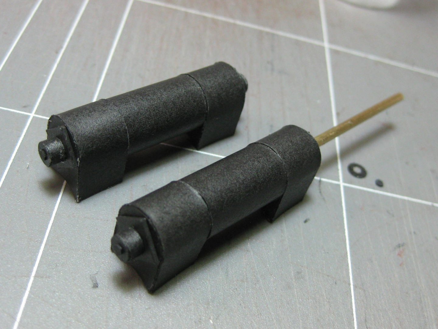
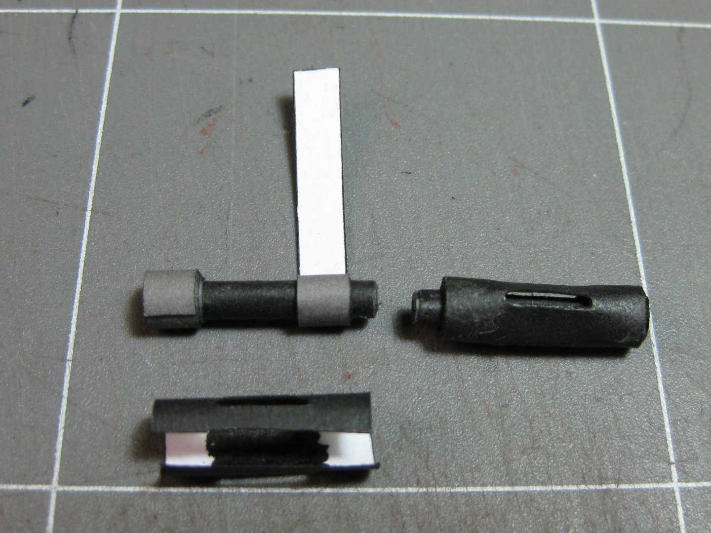
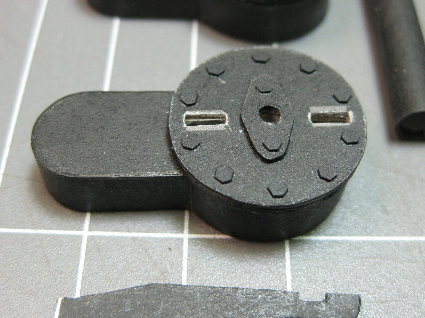
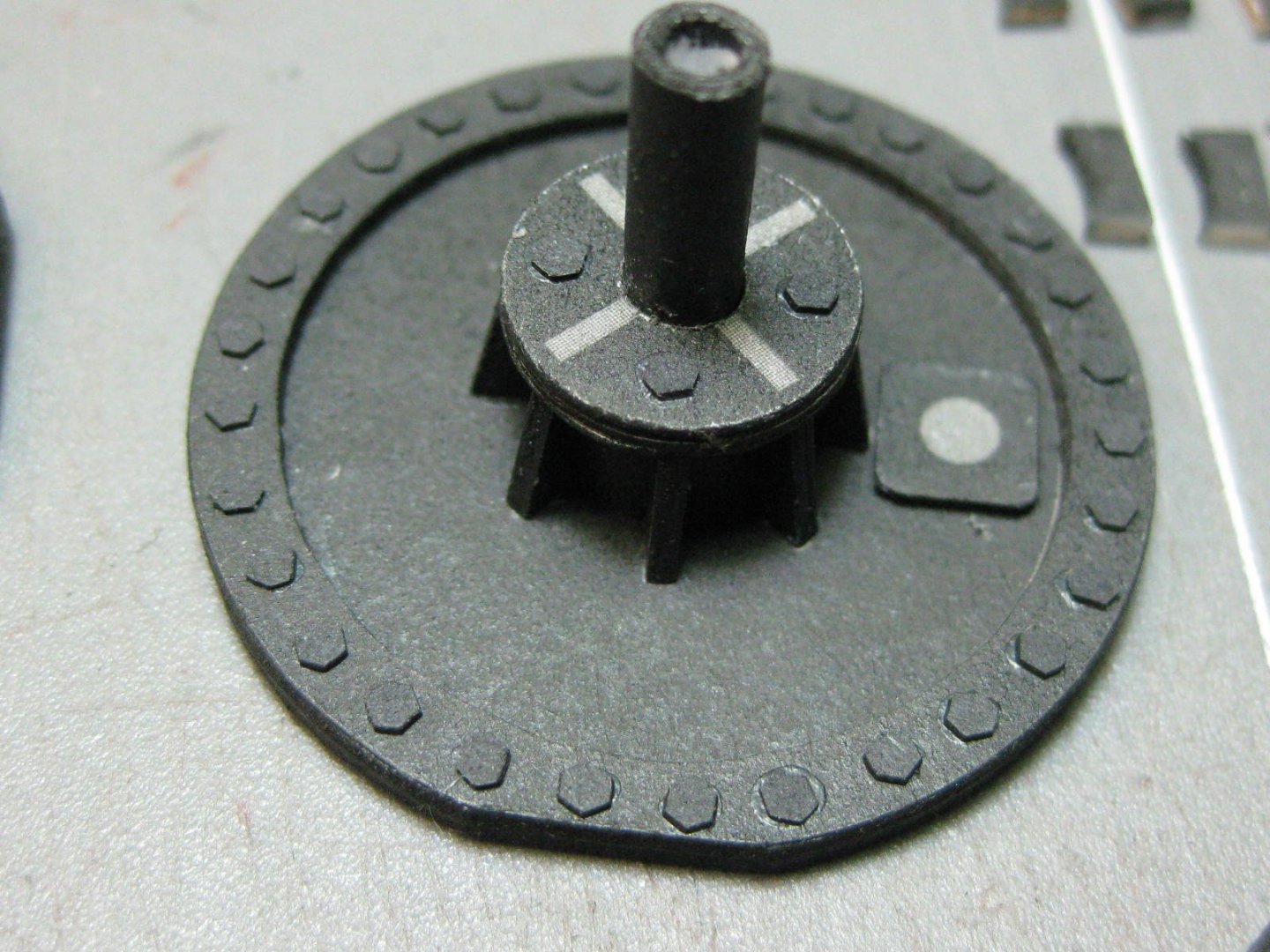
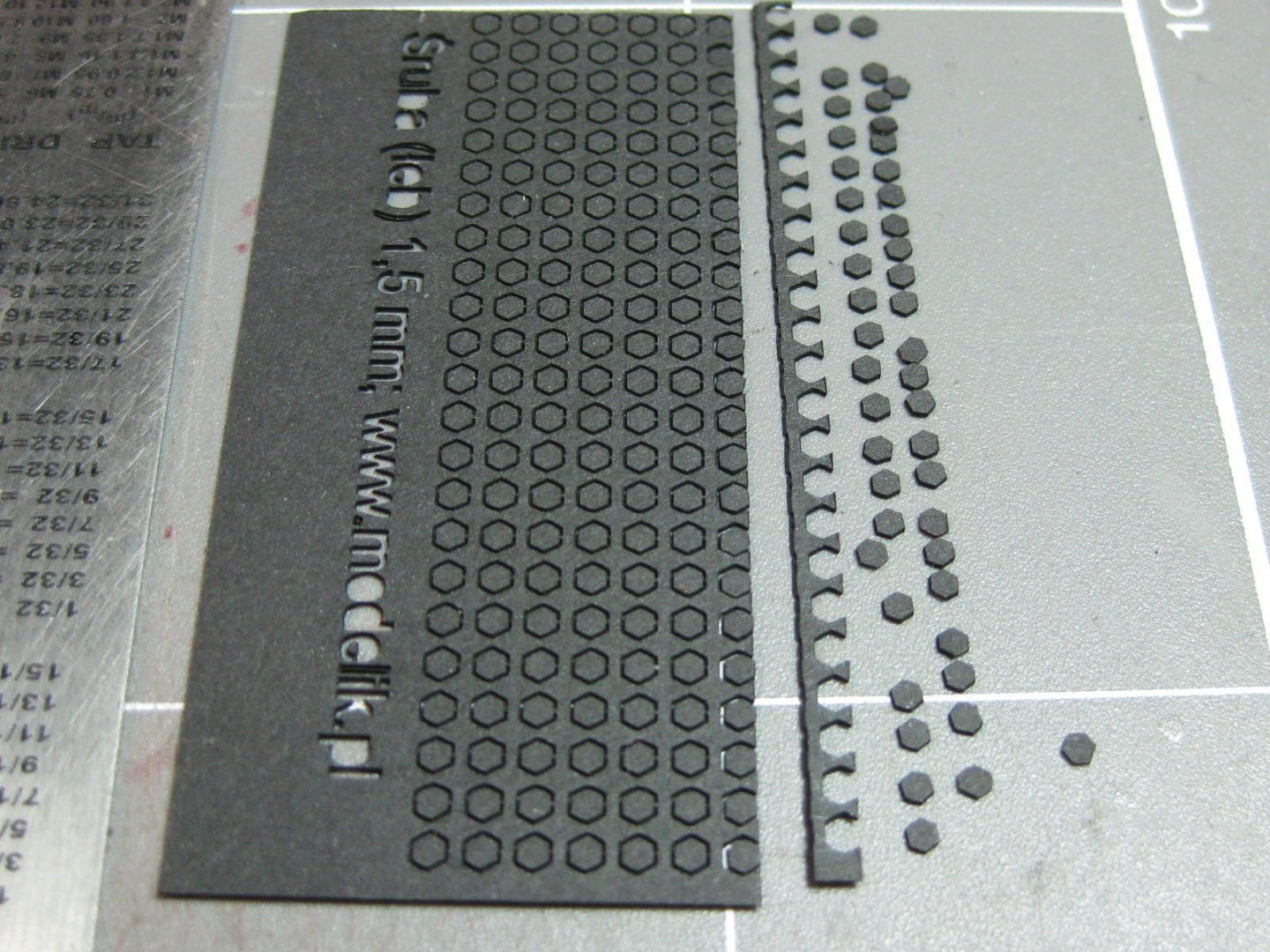
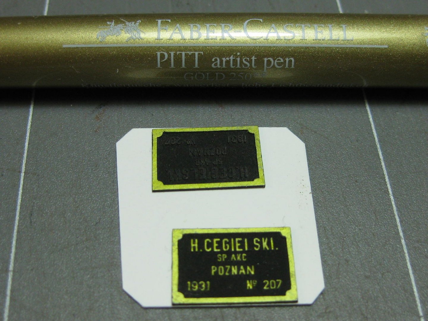
Ken - fire up a paper model ????? I don't think that will end well . I'm going backwards in the following posts to show some of the construction involved in the earlier post of my progress. Quite a bit of work in building the two steam cylinders. I had a few re-does with these, as I didn't understand the basic principles of how they actually worked. Thanks to a couple of other build logs, Stephan and Lothar on German Paper Modelling sites, I eventually got them together the right way up and also WORKING . In these next pics I've cut apart one of my early failures. I actually managed to save every part and rebuilt the little section : The shaft should have gone right through the piece. I had added a paper roll to glue the legs to - wrong : Sometimes a single-edged razor blade works better than a scalpel for cutting parts off as it's about half the thickness : Some of the parts for the end plates etc : How I keep multiple pieces aligned on an otherwise difficult part : These two little pieces were very difficult to roll due to the cutouts in the middle. They turned out quite well : Some finished sub-sections : Lots of laser-cut bolt heads and how I cut them off the sheet : These name plaques turned out really well. They are laser-engraved, the gold colour was applied with a Pitt Pen : The finished cylinders. I'll put the name plaques on near the end of the build : Danny


- 150 replies
-
- 17
-
-
OK Phil, let's try these for starters 1. I'm assuming you're using an acid-free PVA white glue, aka Craft Glue. Use a nice thick one - the more water content the glue has the more warping you will get. 2. Use as little glue as possible to still get a good bond. Too much glue will ...... you get the picture . 3. Use an appropriate applicator. I usually use a squeeze bottle - one with a 2mm tip for large parts like bulkheads or decks, and a much smaller 0.6mm needle-tip one for smaller parts. You could also use a paintbrush for large areas - put the glue into a small container like a plastic medicine cup or similar item and brush it on. 4. Work quickly. You don't need to cover the entire area with glue, small areas without glue won't matter, but you need to get the pieces together before the glue dries too much. If it does, apply another thin layer over it. 5. On very large things like decks - don't attempt to do too much at once. You may need to do it in two or more sections. I usually align it all and tape down the "finish" end to my work surface. Then I tape a couple of "stops" to each side and the end of the surface so it is easily re-aligned accurately later. Now I run a bead of glue down the "start" end while keeping the "finish" end aligned in the stops, press it down and let it dry enough so it won't shift. Now lift the "finish" end and start applying glue at the "start" end, pressing it down with a flat piece of wood about 20mm behind the glue as you go. When it's all done press the entire deck down with your flat timber and - this is important - bend the piece gently (ends down, middle up) to "pre-stress" the part. Now slip it under a sheet of glass on a flat surface and let it dry THOROUGHLY (over-night). I hope this helps a bit. The main point is - don't use too much glue. Cheers, Danny
-
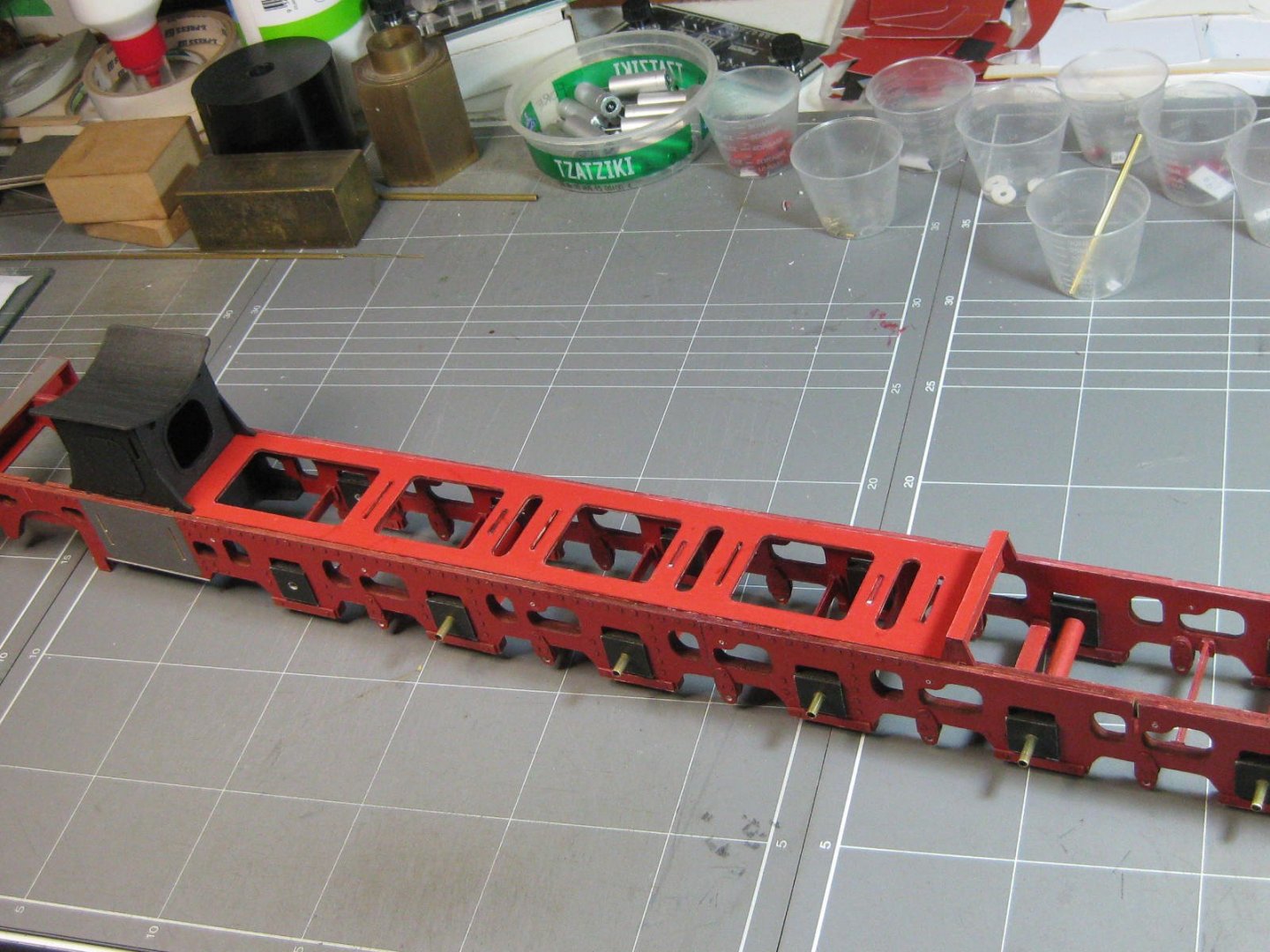
I'll post an answer to that in my next one later today Phil, I'm in a bit of a hurry at the moment and wanted to show an update on my loco. Here's where I'm up to at the moment, details of how I got there will follow a bit later : Danny

- 150 replies
-
- 22
-
-
QUICK-FIND INDEXES to BUILD LOGS FOR KITS
Dan Vadas replied to Dan Vadas's topic in - Index of all kits by brand and subject
No worries Peter, always glad to help out someone trying to do the right thing. To become a member of the Nautical Research Guild (NRG) you can go to the bottom of any page and click on the NRG Home Page link in "Helpful Links" and go from there - on their home page is a button on the right-hand side to Join or Renew Membership. Or you could just click on THIS LINK (which does the same thing ). Cheers, Danny -
QUICK-FIND INDEXES to BUILD LOGS FOR KITS
Dan Vadas replied to Dan Vadas's topic in - Index of all kits by brand and subject
Hi Peter, You said it - "we are all human". Your build log was in the "Wooden Ships" Index, you hadn't added "RADIO" to the title so I didn't know that it needed to go into the R/C Index. I've edited the title of your log for you and updated the R/C Index. The other log by NMBROOK has been deleted, he did it himself. He has had some kind of issue with this forum and is no longer a member. His other build logs and posts are still there, just hidden from the general membership as he has been Banned by this forum. This is normal forum policy - we don't delete the content of Banned members in case the issue is resolved at a later date and the member is restored. In that case all his/her topics and posts are then "Un-Hidden". Have a good day. Cheers, Danny -
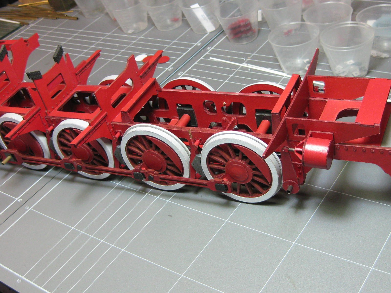
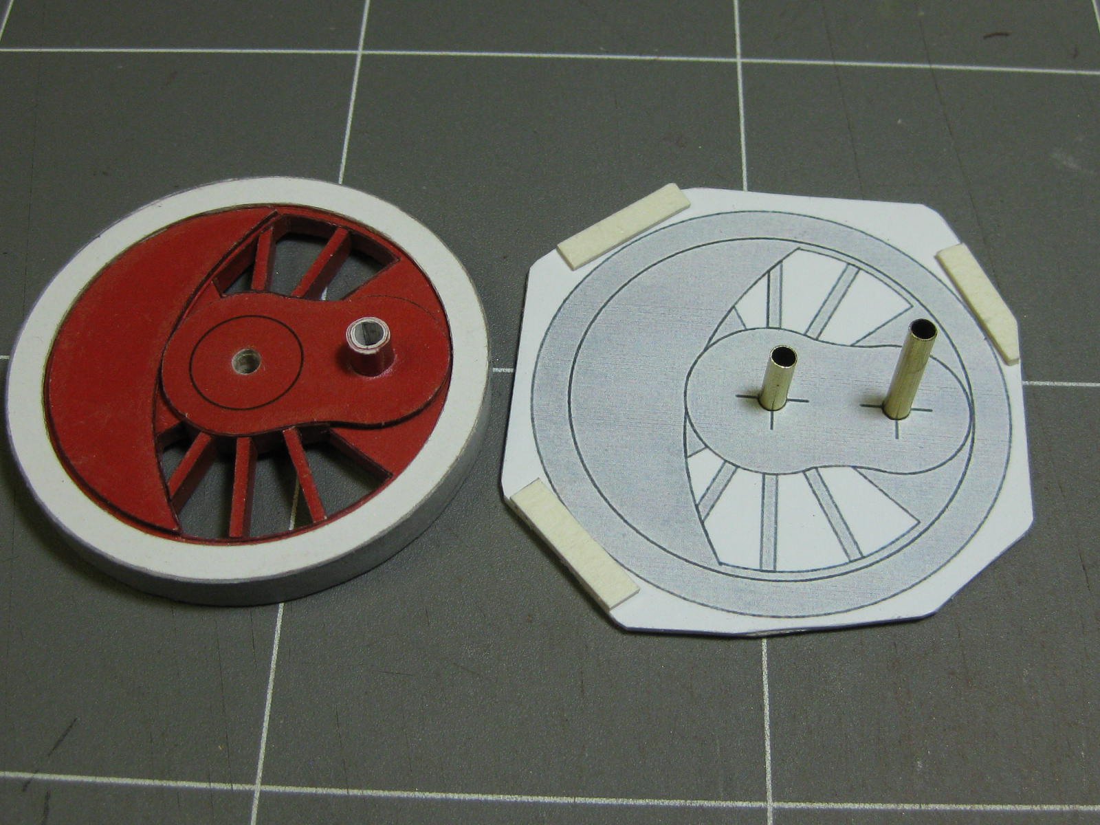
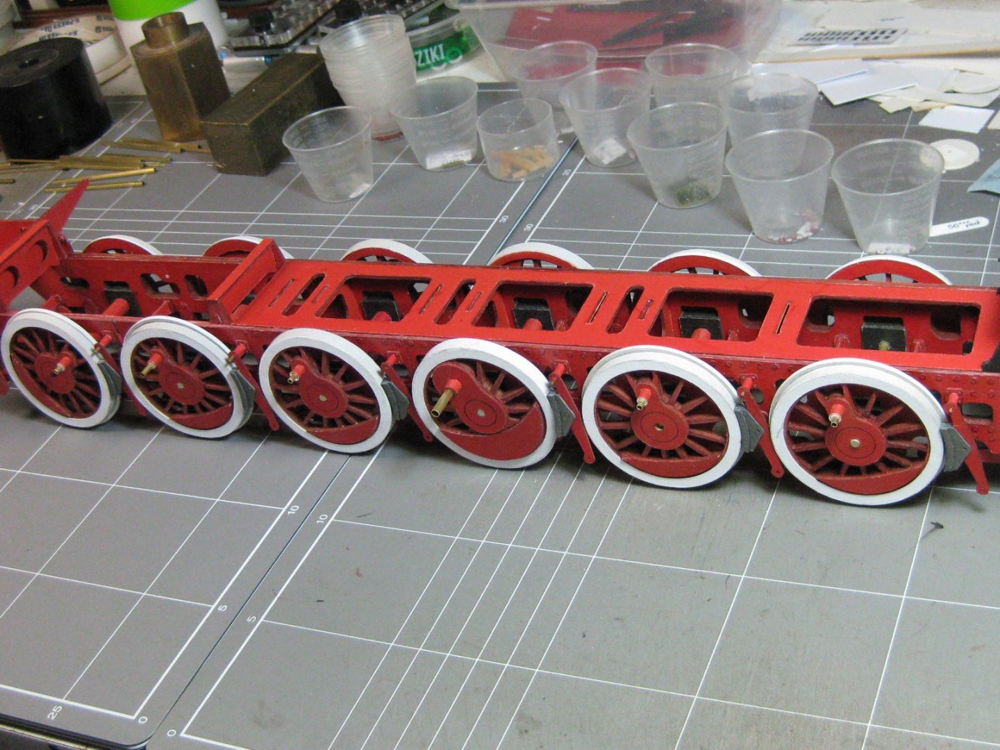
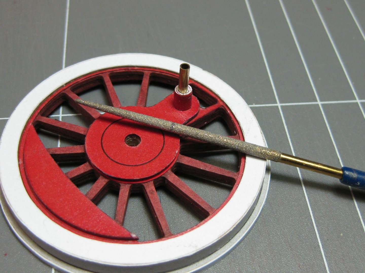
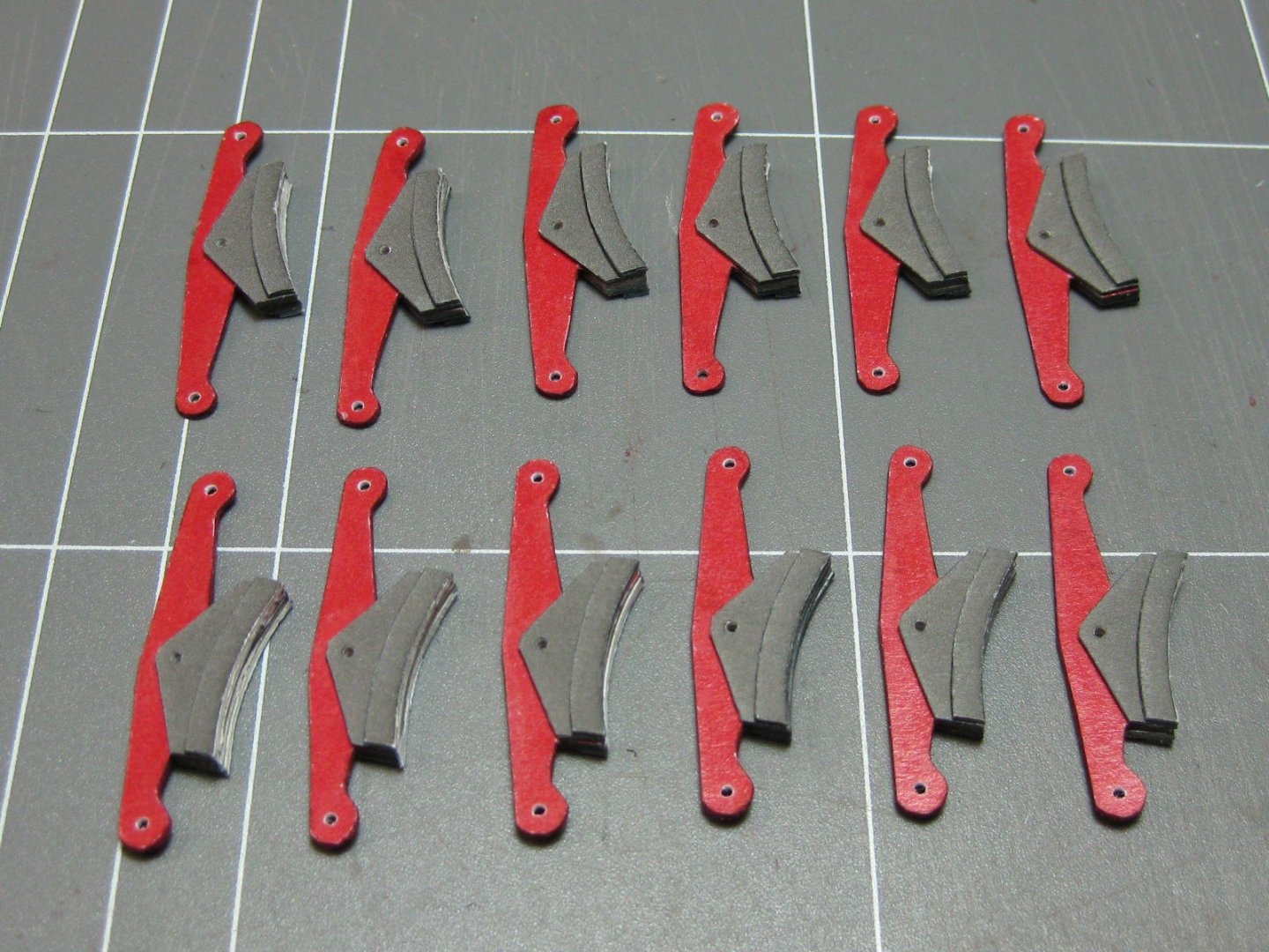
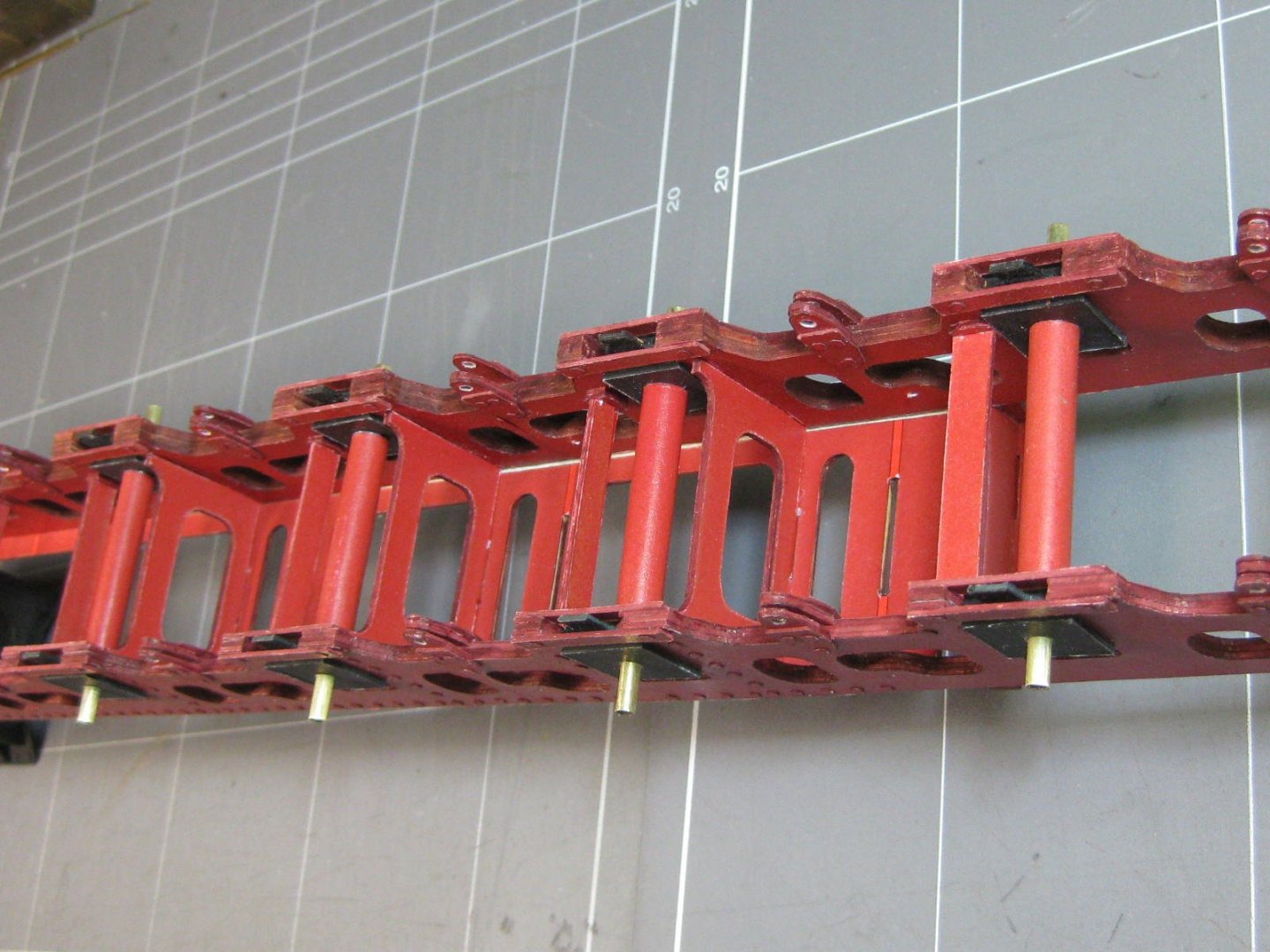
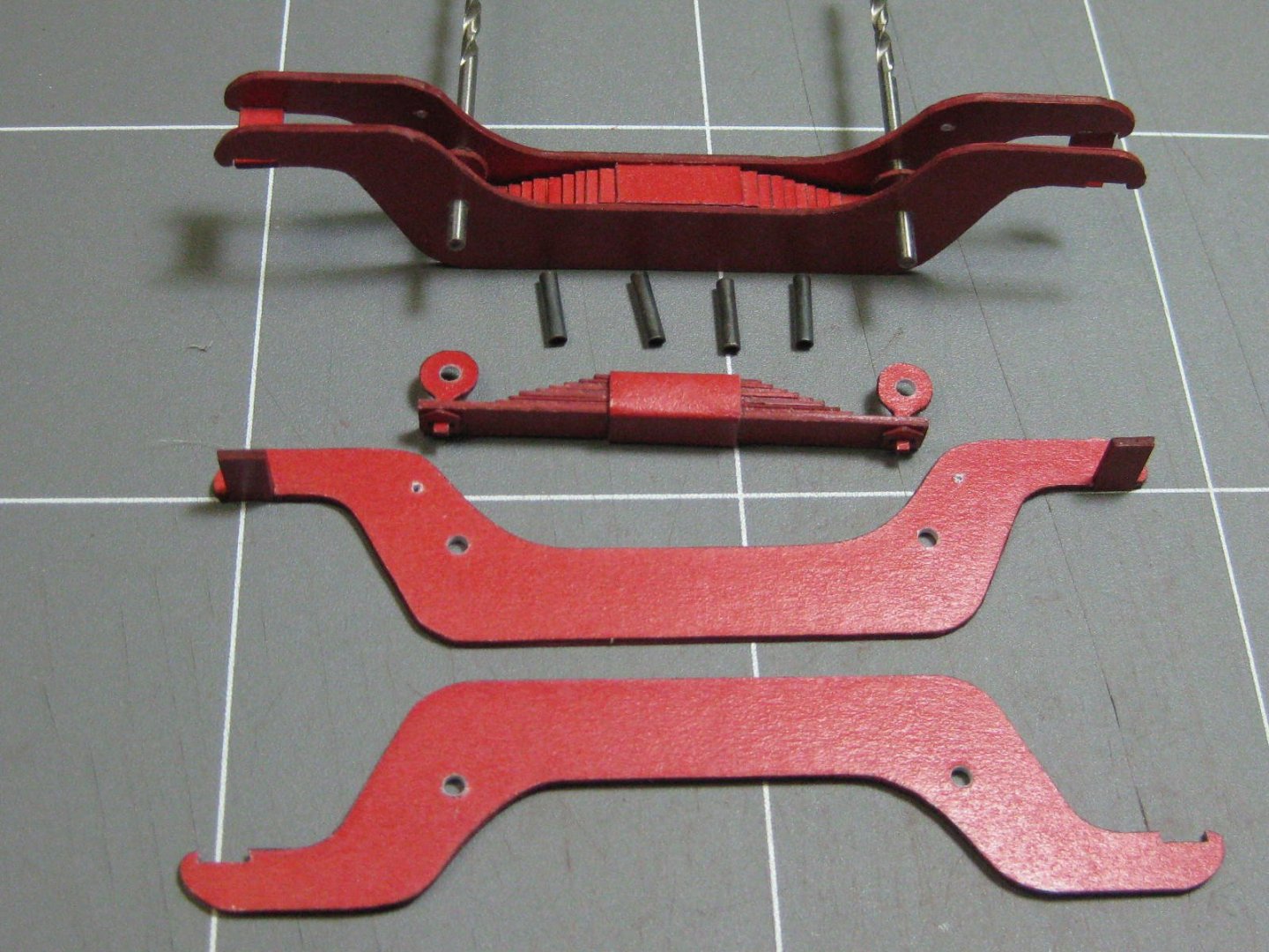
I've fitted the axles to the frame. At this stage they are all a tight fit except the Driving wheel one which can turn freely. The wheels will be glued to this axle so that both sides will turn together, and the others will freewheel on the axles - at least that's the plan so far, we'll see how things work out : I've also fitted the crank pins to the wheels and filed out the centres with a small diamond-coated round file. These things work really well on paper : I'm leaving the wheels aside for the time being - I've ordered some 2.5mm styrene rod which I'll use to "rivet" the wheels to the axles. Meanwhile I fitted all the brake suspension using the springs I made earlier. I had a drama with the swing-arm brackets, the clear coating on all of them let go when I started working on them so they needed a re-do which consisted of scraping off the coating and re-gluing them - much better : The springs and swing-arms fitted : Finally for this stage I made up the two main cranks : Danny

- 150 replies
-
- 23
-
-
How to use a Circle Cutter by Dan Vadas
Dan Vadas replied to Dan Vadas's topic in Modeling tools and Workshop Equipment
Yep, the Olfa isn't much good at all. It's the first one I bought and found the same sloppiness - I'm glad I managed to snap it . I don't know if you noticed the pic of the new one I bought, but the arm adjusting lock isn't a screw but a plastic sliding wedge (there's another on the back for the "large circle extension") which does a good job of locking the arm without any freeplay. The whole unit is also a bit thicker than the Olfa, which takes a lot of flex out of it - and it hasn't snapped yet either . Danny -
How to use a Circle Cutter by Dan Vadas
Dan Vadas replied to Dan Vadas's topic in Modeling tools and Workshop Equipment
That's weird, now mine also goes to the red one above. As you said - a quirk . Or maybe it was just me opening the wrong Window in the half-dozen or so I had open at the time . Cheers, Danny -
How to use a Circle Cutter by Dan Vadas
Dan Vadas replied to Dan Vadas's topic in Modeling tools and Workshop Equipment
Bruce, that's the same one I posted the Link to in my first post . The accompanying video is worth a look, but don'y be fooled by how easy she makes it look - they are rather large circles she's cutting in it . "Did your wrist hurt after making the 120 cuts for the 12 wheels?" Not really Moab, I didn't make them all in one go - that would have been the equivalent of tying Ratlines on a 3-master . Glad to be of assistance guys. Cheers, Danny -
Here you go David and Moab, I've made a mini-Tutorial on how I use it. I hope you find it useful. Thanks all for your remarks and Likes. An update will be following shortly. Cheers, Danny
-
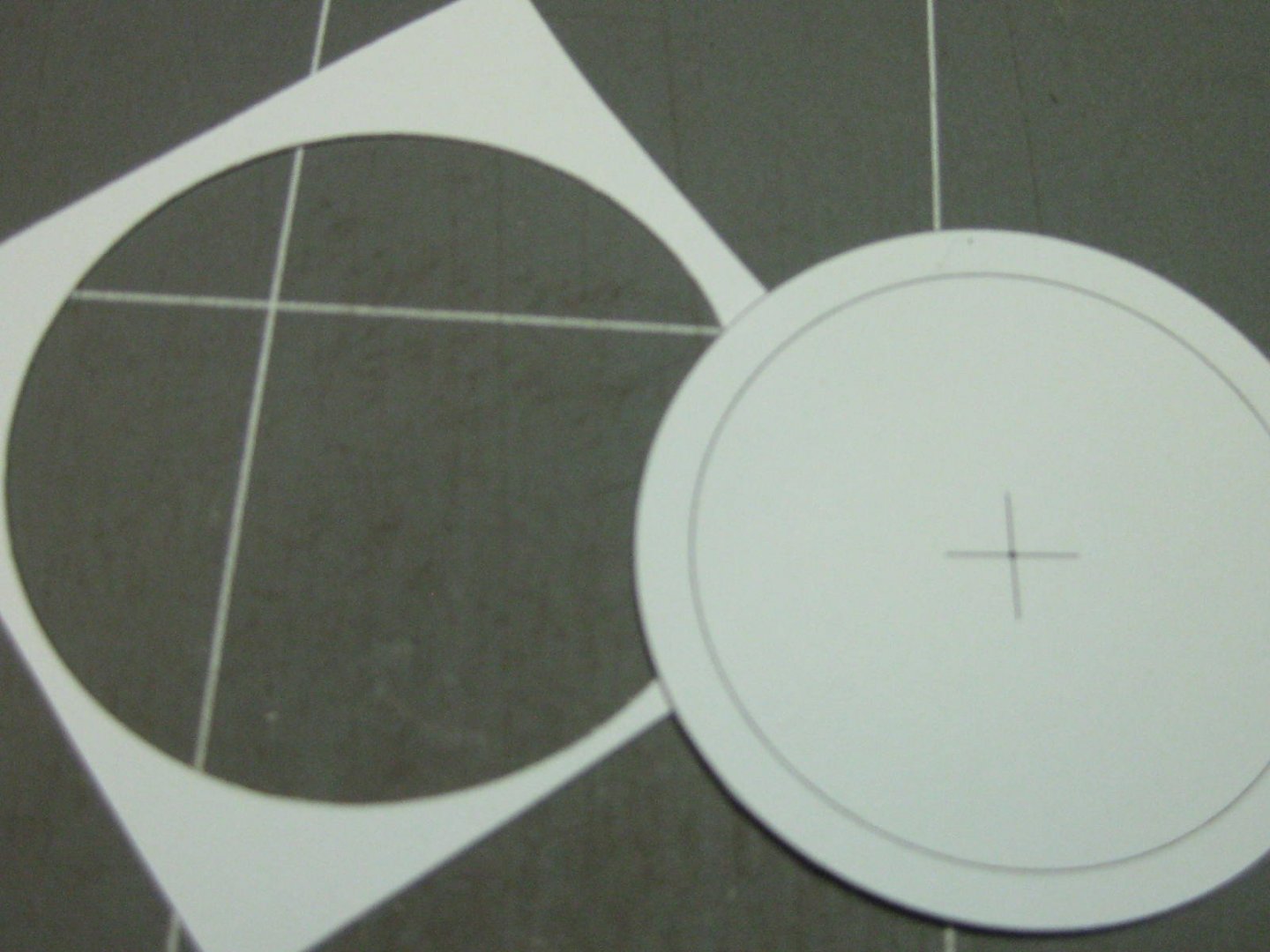
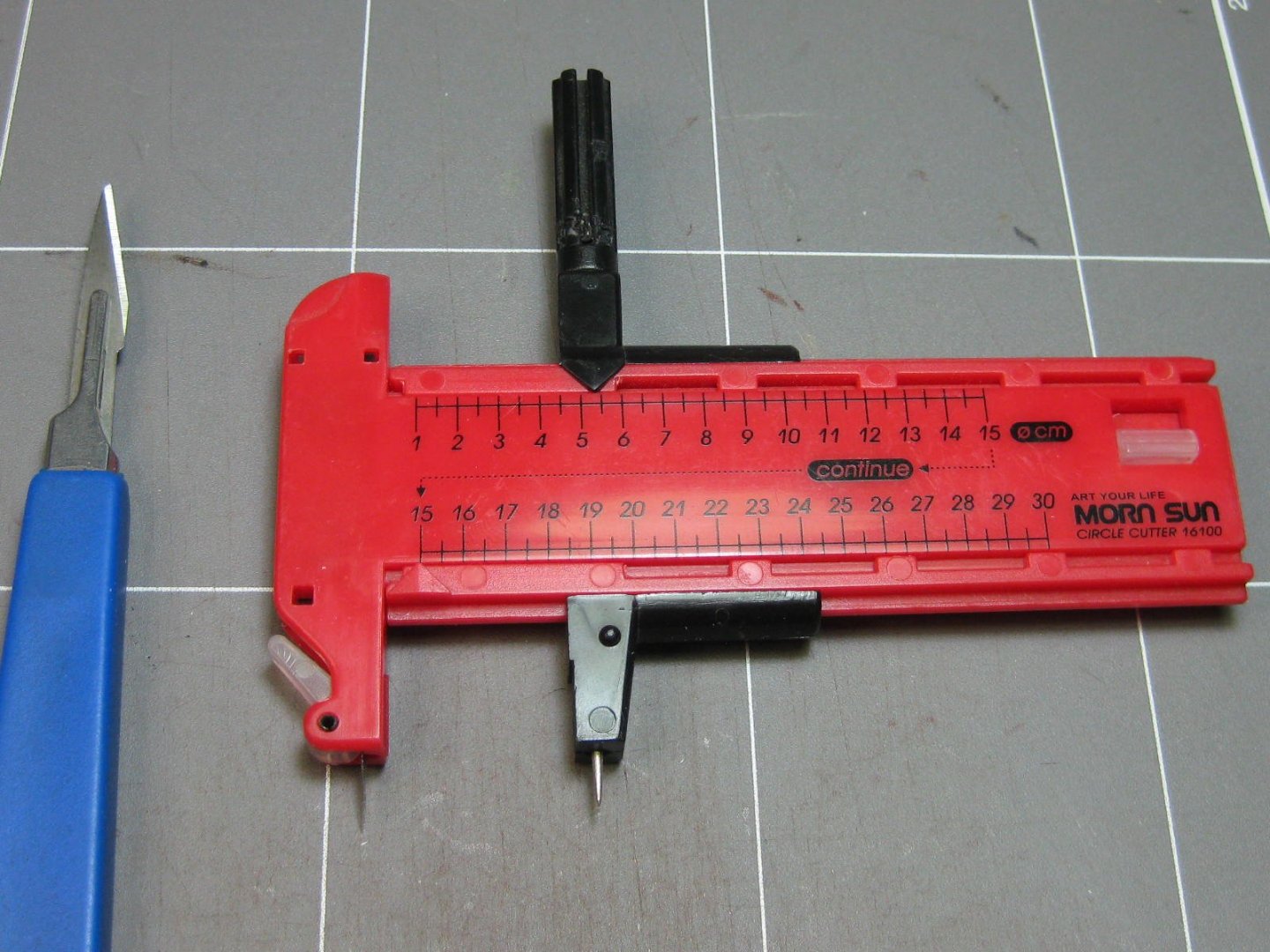
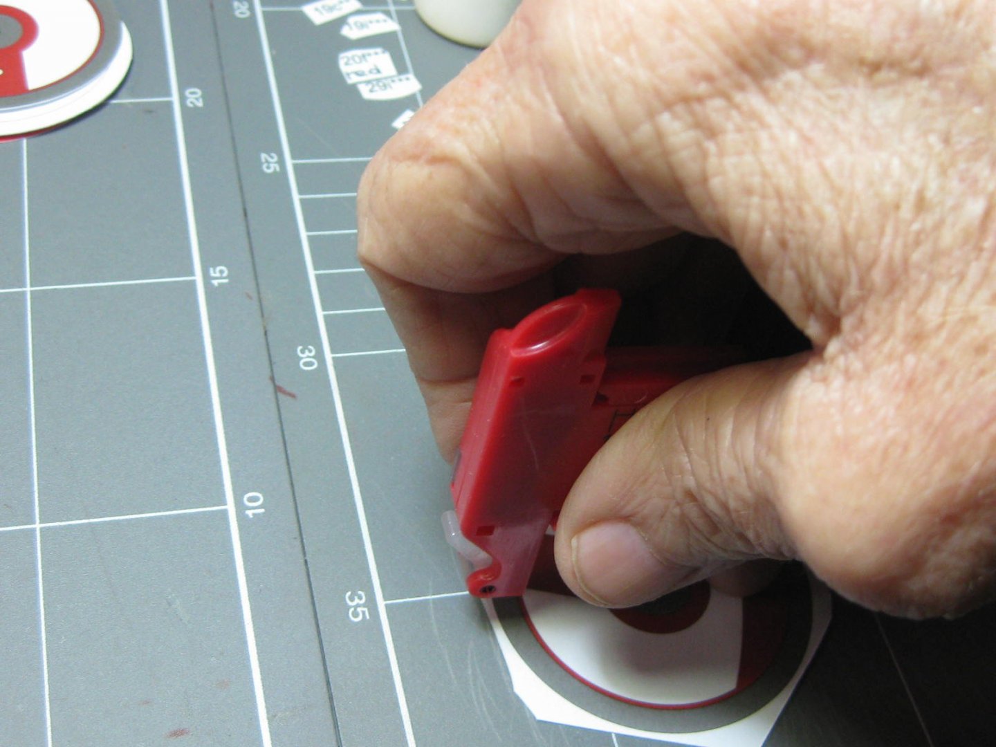
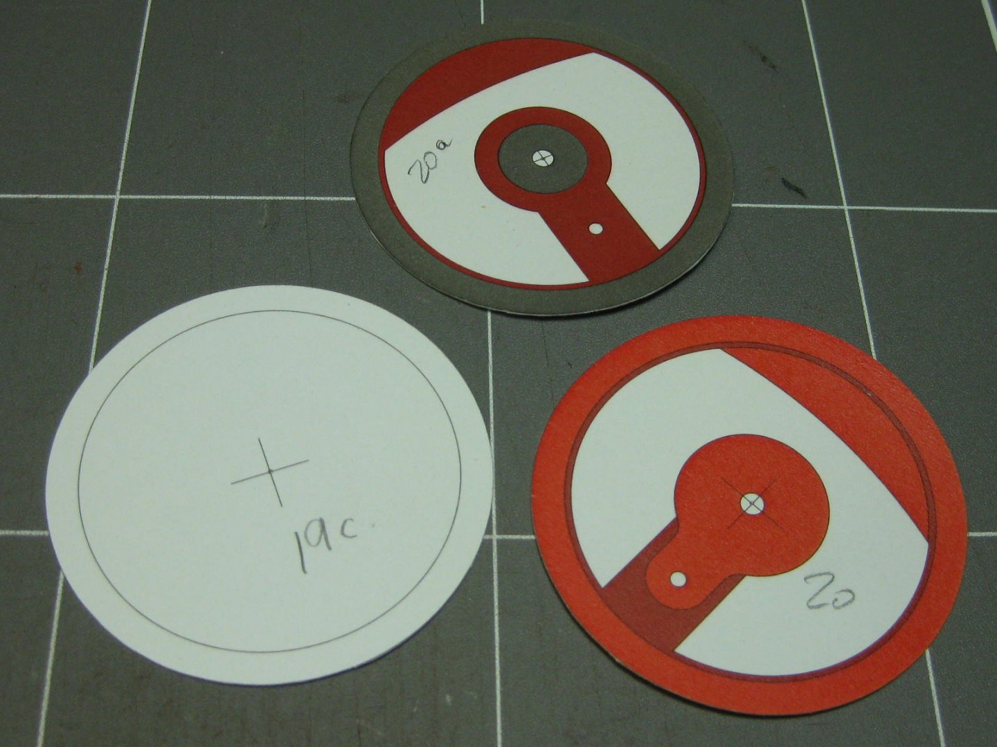
Hi all, Some time ago I bought one of these Circle Cutters, thinking it might be a useful tool. I gave up on it after a couple of tries, relegating it to the "Useless Tools" drawer : Recently I needed to cut about 200 circular discs (including the inner cuts of 1/3 of them) from thin card for the wheels of a Locomotive I'm building from Card - I started a Build Log for it in the Shore Leave forum (a Link to it is HERE). So I resurrected this device and gave it another go. Here are the results of a bit of (successful) experimentation : And here are the secrets I discovered on how to use this formerly useless tool. 1. Buy a decent quality one. I actually snapped the first one I bought (one like this)- it broke under a bit of pressure. I can't really give you any tips on which one to buy, but I found the one in the picture above to work OK. There are probably better ones out there - check on Ebay or Amazon. I also found THIS beast, a German made Ecobra - I have no idea of the cost of it, but it looks quite sturdy and comes with several different types of cutters. There is a video on how to use it in that Link, it's a bit different to my tips - they make it look SO easy . 2. Always use a SHARP blade. As with any type of cutting blunt blades are a no-no. The centering needle also needs to be sharp or it slips and won't work properly. I only had to change to a new blade after cutting about 150 circles. The cutting face should be pointing toward you, and the part rotated in a clockwise direction. 3. Use a Cutting Mat. The needle needs to be stable, and it can be pushed into the mat without damaging it. An unstable needle will slip. 4. Keep the tool VERTICAL when cutting on anything other than thin paper. This is very important when cutting through thicker or tougher material, as the blade will wander off-line if it's held on an angle. I use the grip in the pic below, with the end of the centre shaft nestled in the palm of my hand between thumb and forefinger : 4. Use LIGHT pressure on the blade and take small "bites" as you use a combination of moving the blade and rotating the card at the same time with your other hand, holding the part firmly down against the mat so it can't rise up and change the angle of cut. This applies to smaller diameter circles like the one above, larger circles are much easier to cut. 5. When cutting thicker card (0.5mm or thicker) several rotations will be needed. Don't attempt to cut right through in one pass, the blade WILL wander off-line. How many rotations will depend on the thickness and density of the material being cut, as well as how much pressure you put on the blade. Less pressure is best. 6. DO NOT push the blade downward so hard that it bites into the cutting mat more than making a slight scratch. The blade will bind up and shift. 7. These tools are not designed to cut through wood as it will follow the grain, but it can be done in densely grained timber like Boxwood or Swiss Pear. Many more rotations of the circle and much lighter pressure on the blade will be needed, especially as the blade follows the grain. 8. Cut OUTER circles FIRST if multiple cuts are needed on a part, or you will lose your centre. 9. Forget the scale on the tool, it isn't particularly accurate. Use a rule to measure the diameter, or use the part itself. Test it on some scrap before cutting the part, to make sure it is set up OK. 10. Some experimentation will be needed before starting to cut the "real thing" to get the feel of it all. Take the time to get it right on some scrap before committing to the printed part of a card model. Here are the results of some of the wheels I made. There are up to 10 discs in each wheel : Cheers, Danny


- 11 replies
-
- 18
-
-
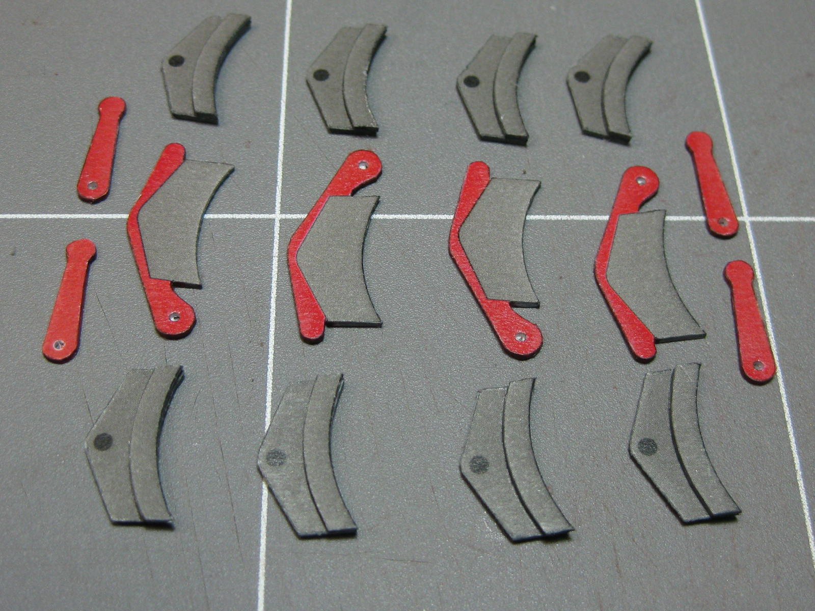
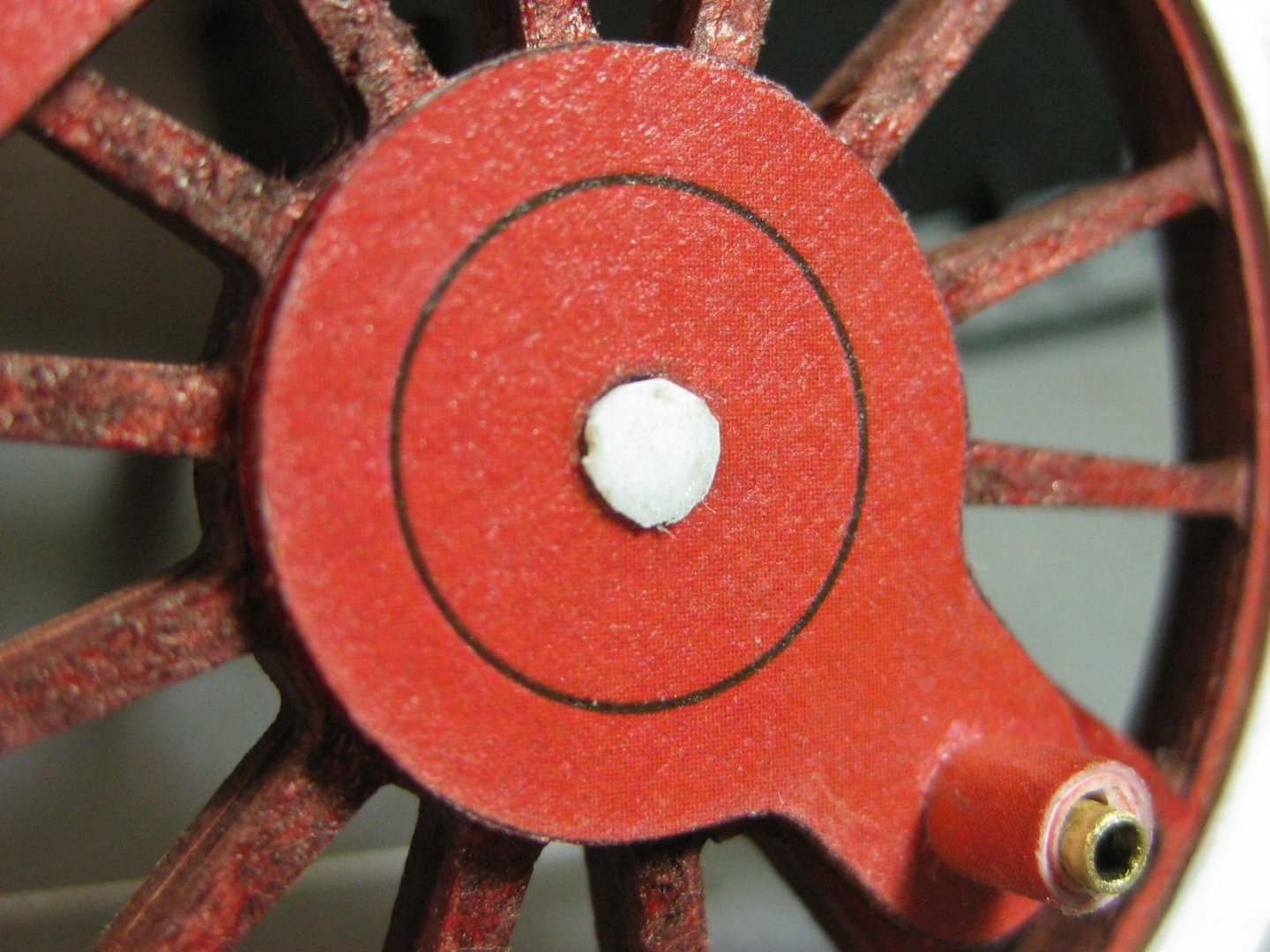
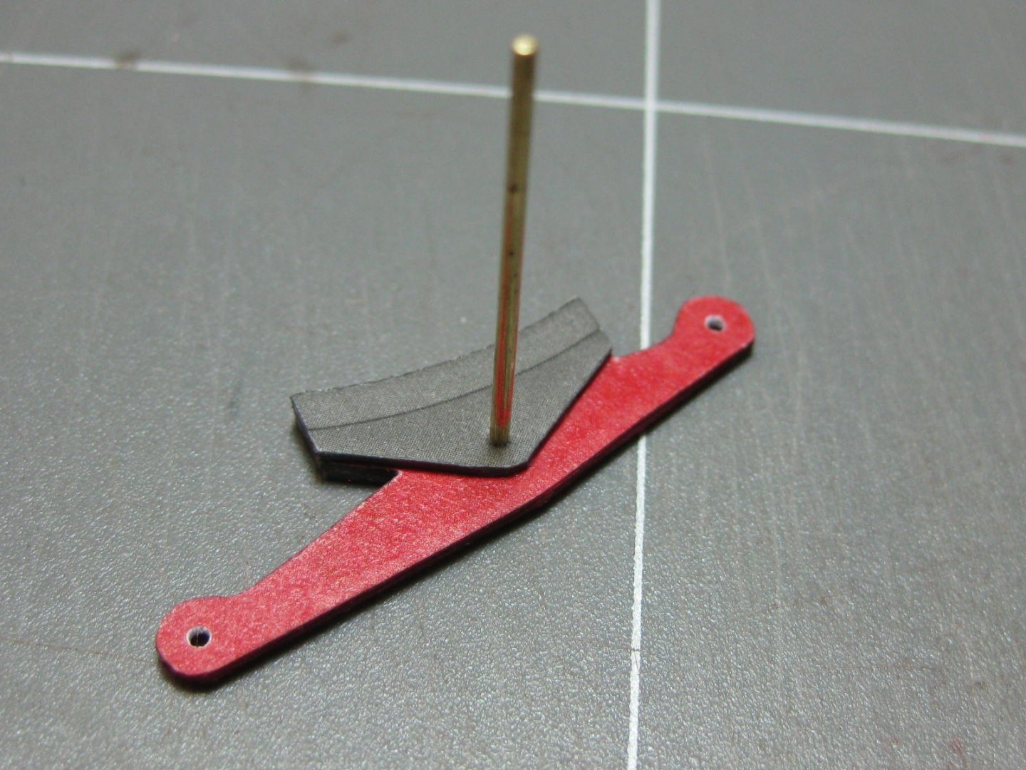
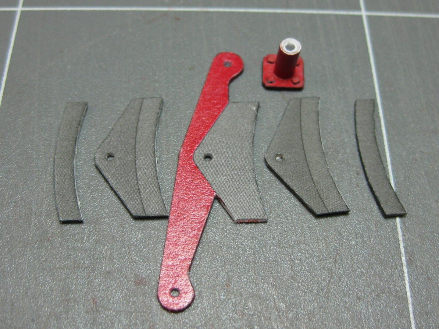
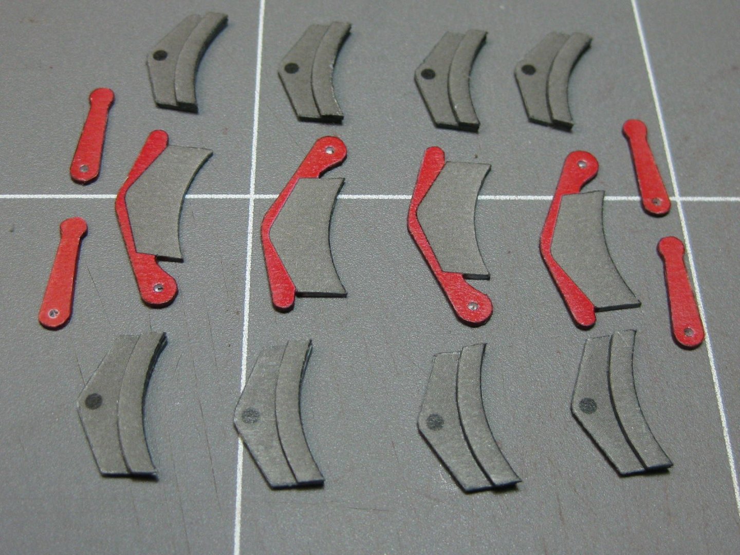
Now I fitted the crank pins to all the larger wheels. I've glued them in with PVA, so I cut a groove in the pin with a Xacto knife. This stops the brass pin from slipping : I fitted the six axles. They are all a nice tight "push-in" fit and shouldn't move again. However I filed out the hole for the Driving wheel axle so it COULD turn - once the cranks are installed both sides will then turn in unison : Now it's on to the main brakes, quite a big job. Here are the parts for one of the 12 brake shoes. I've glued the inner pads on, but I may have to remove them again later (easily done with a single-edge razor blade) if there isn't enough clearance to the wheel flange. I had to do this on the bogie's brakes, and Stephan also found out that it was necessary on his model. We'll see : I used a 1mm wire to keep everything aligned while gluing the pieces together : All done. The contact surfaces will be cleaned up as I fit each assembly, they will need to be sanded to get clearance to the wheel rim : On to the brake control arms. All the parts are prepared ready for fitting together : Once again a simple jig made accurate assembly easier : That's it for now. I'll move on to fitting the brake assemblies to the main frame next. Cheers, Danny


- 150 replies
-
- 20
-
-
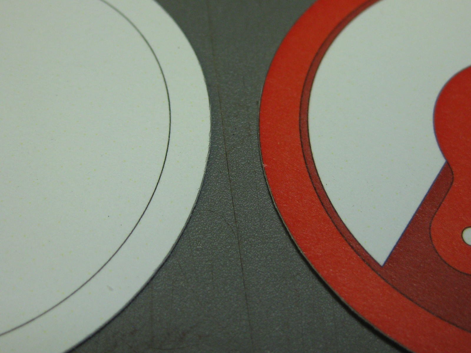
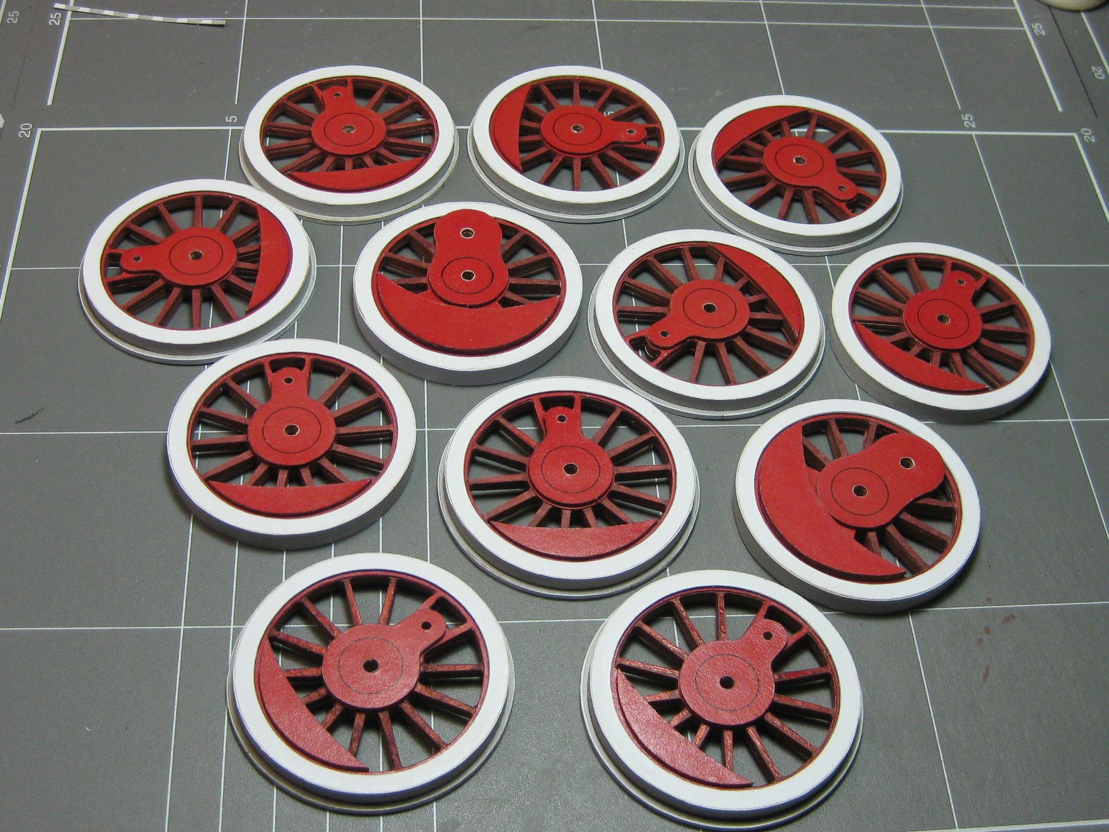
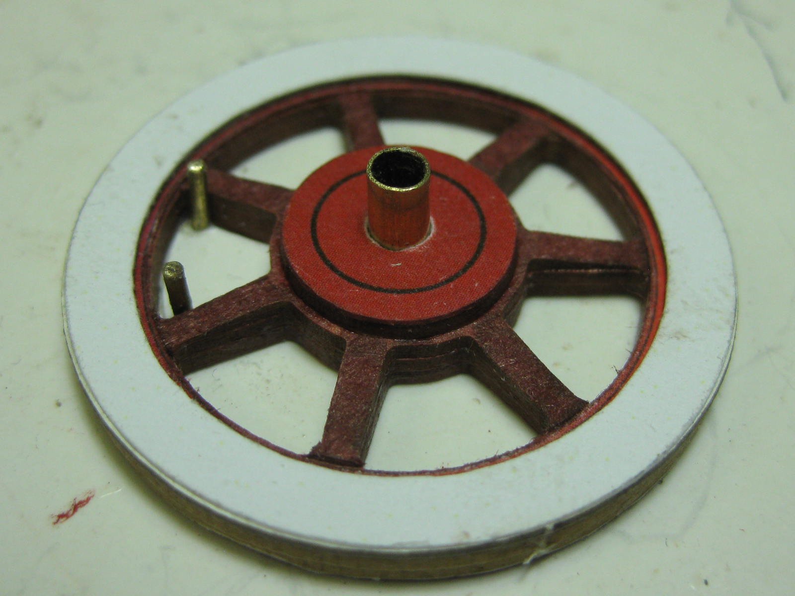
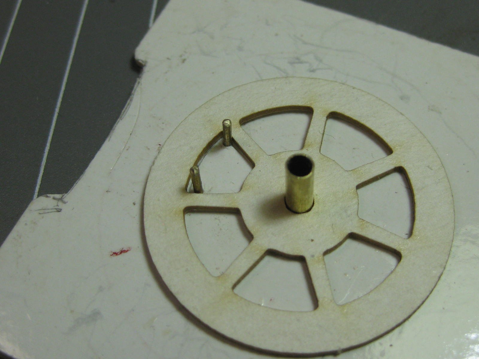
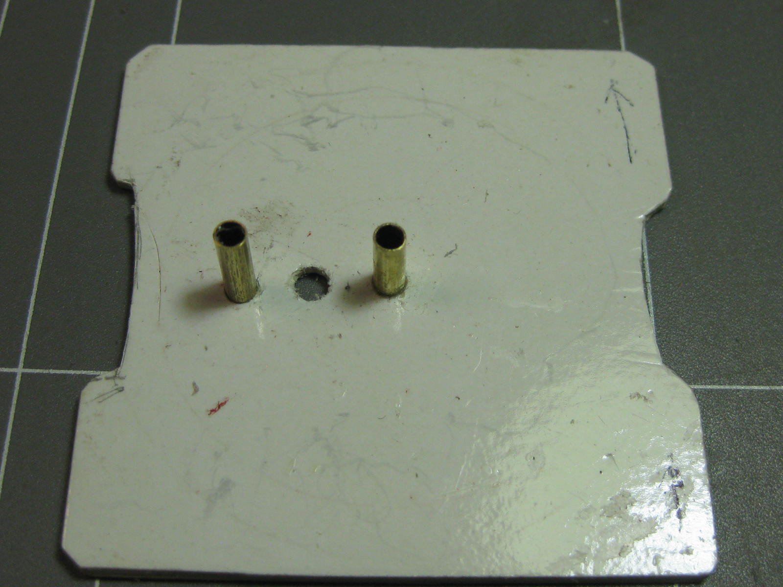
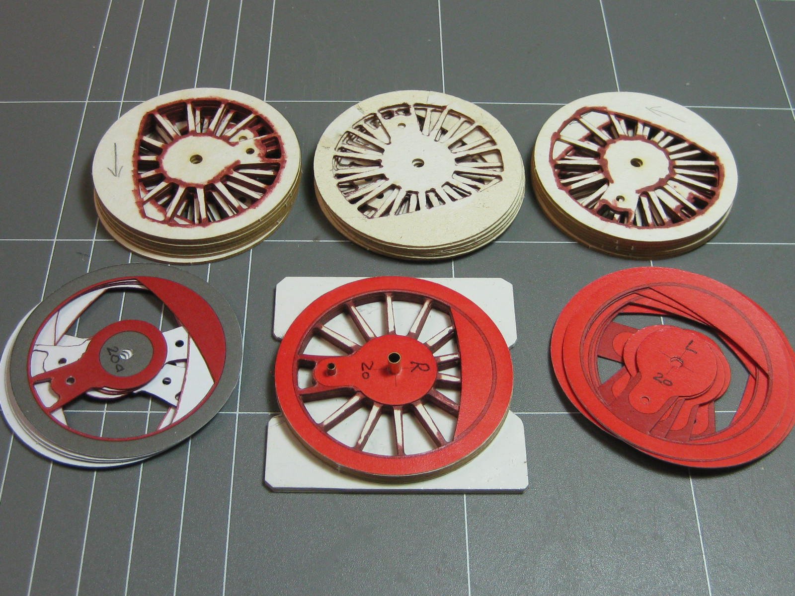
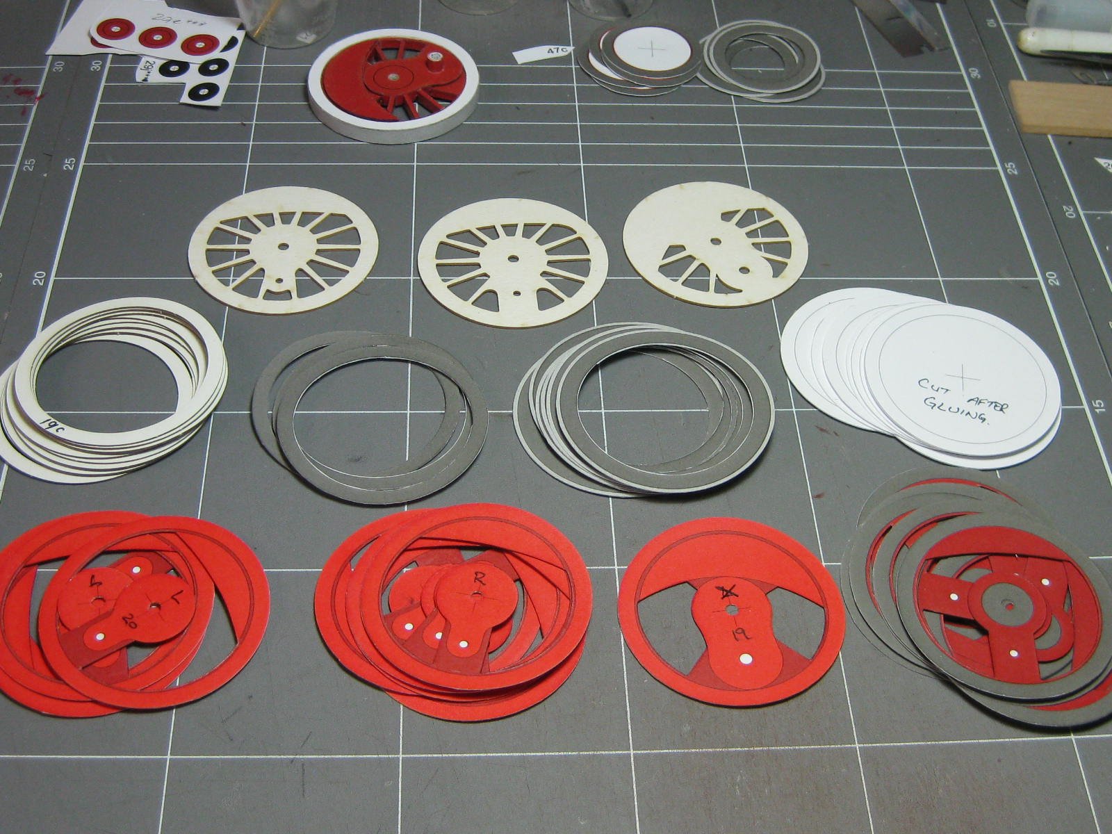
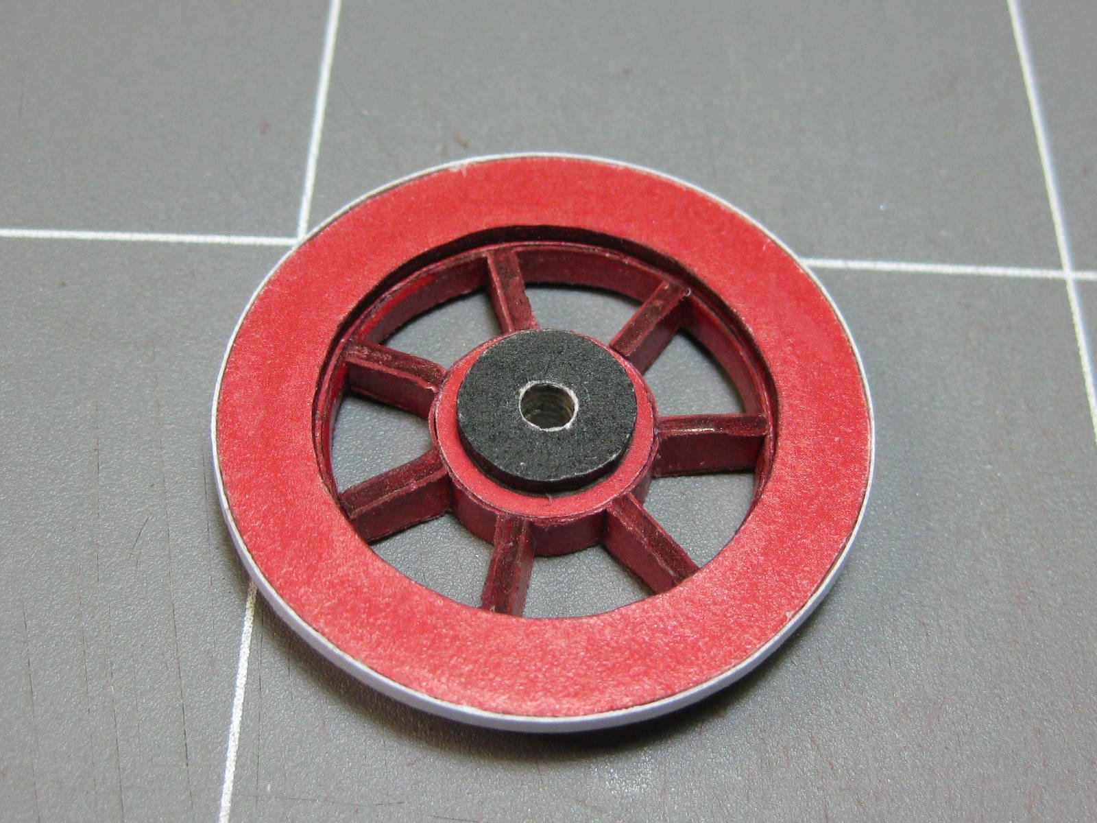
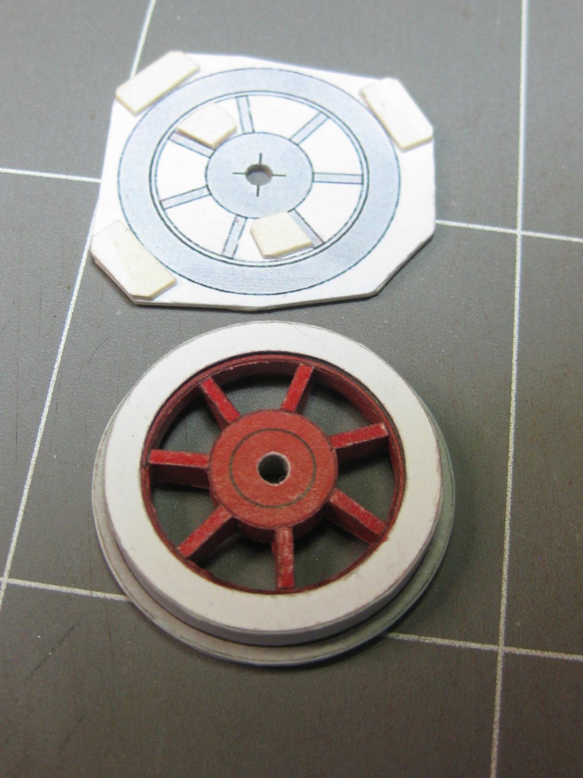
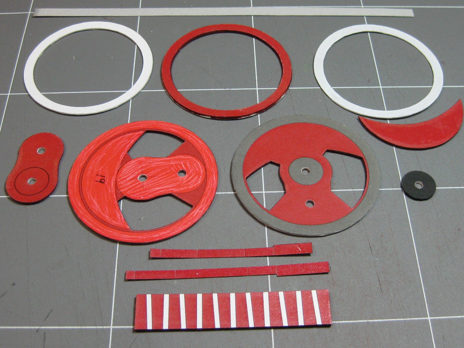
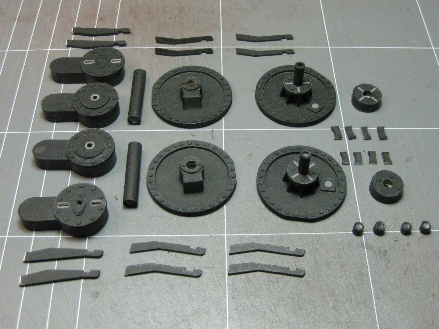
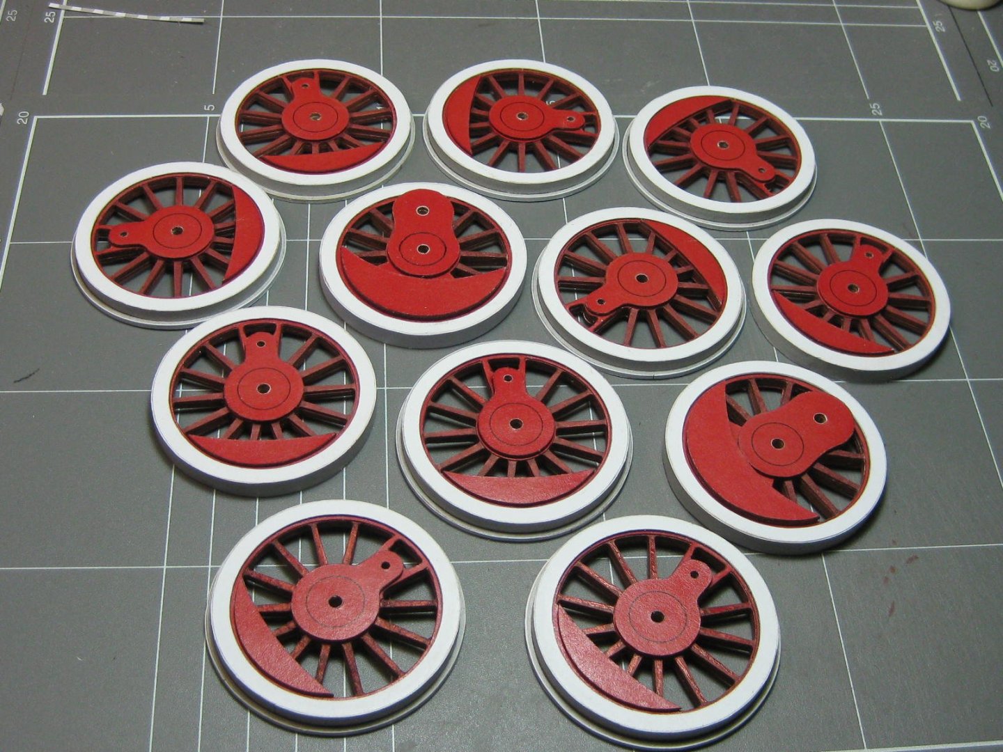
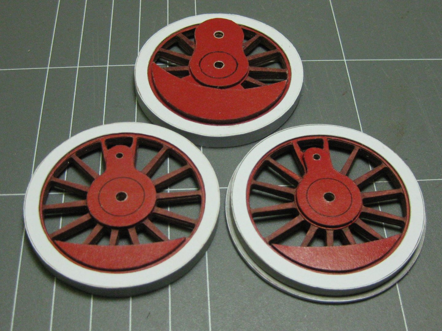
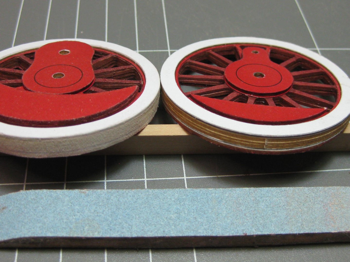
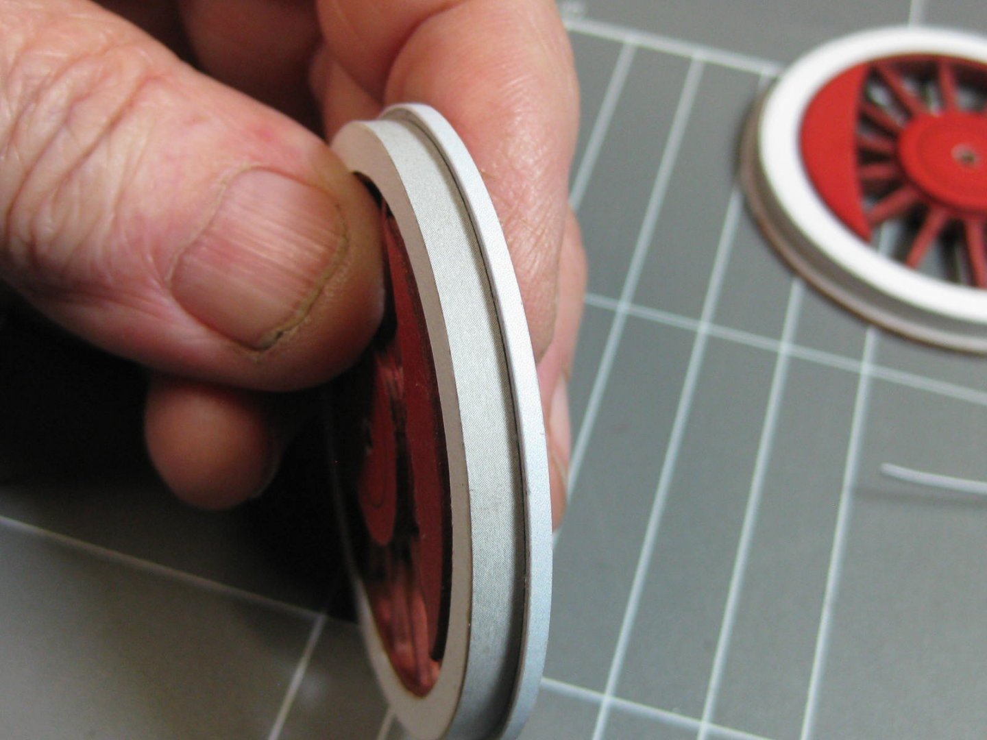
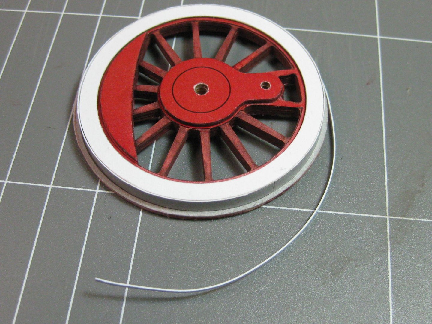
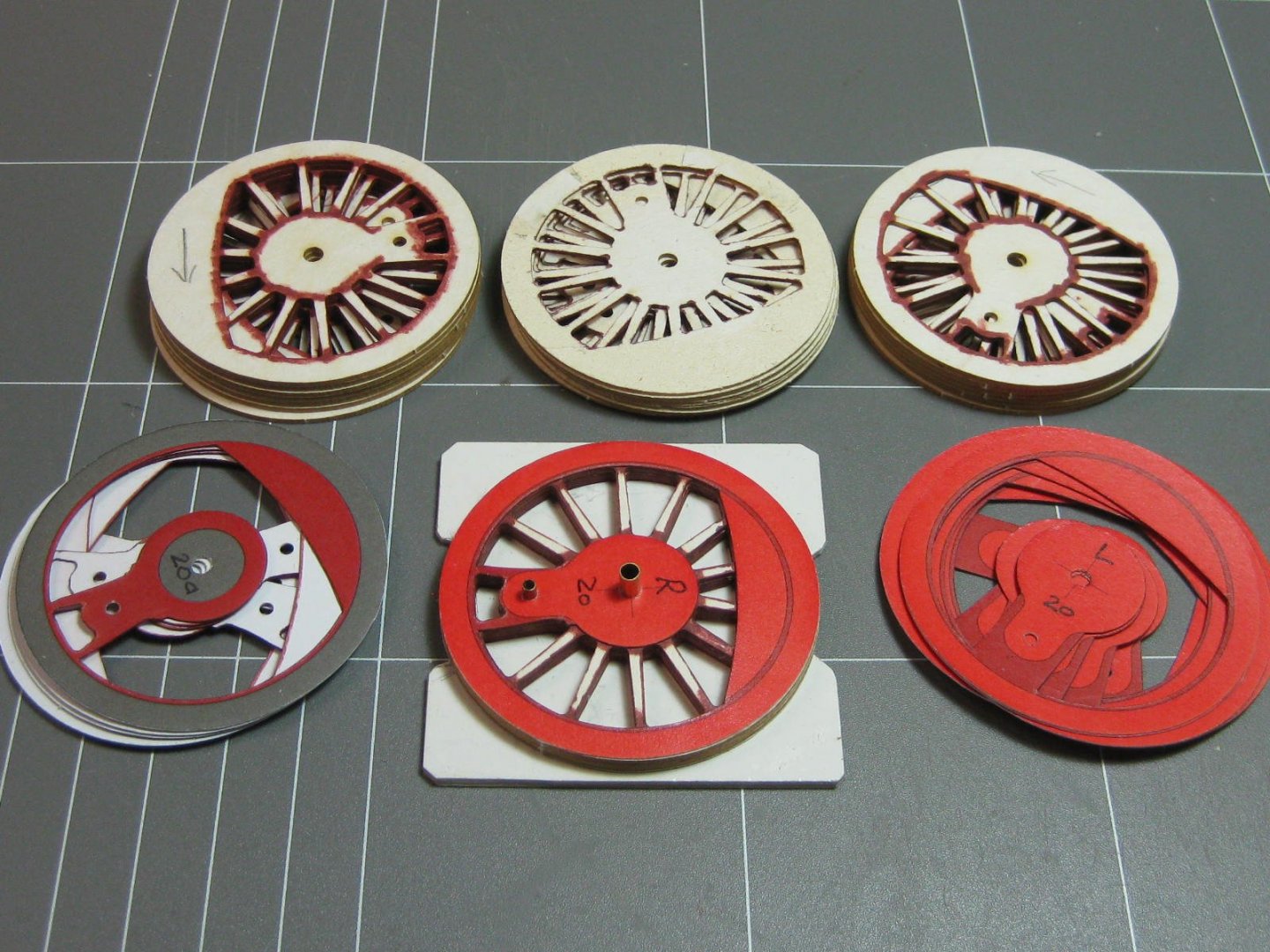
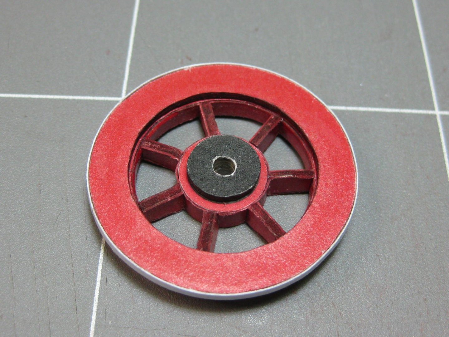
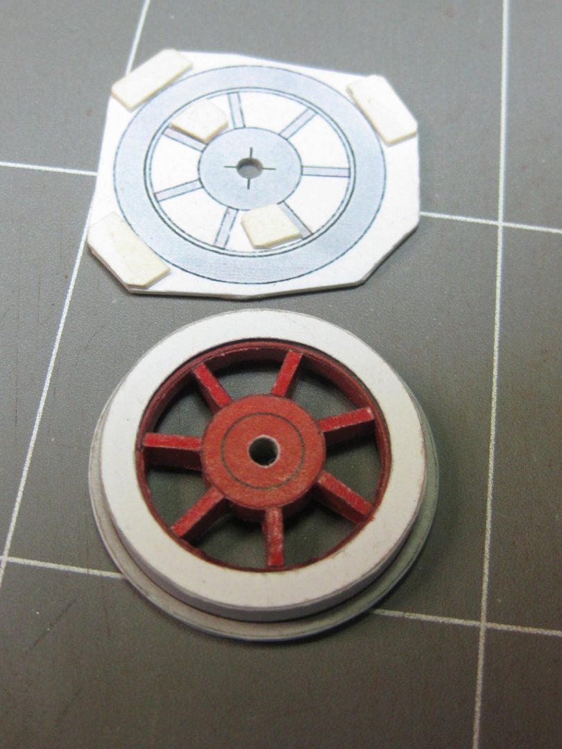
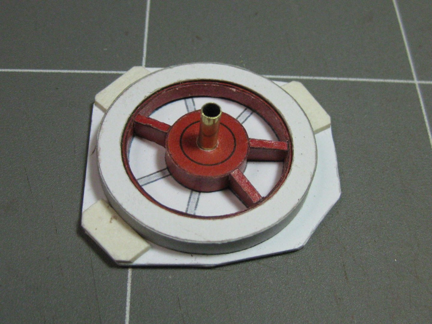
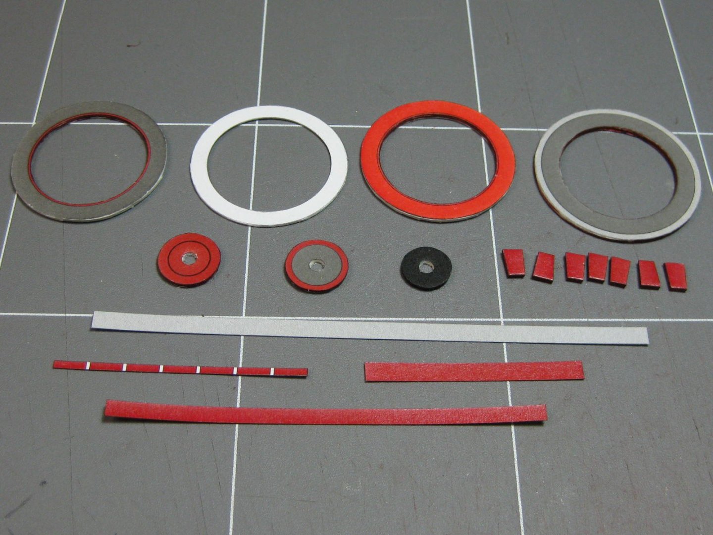
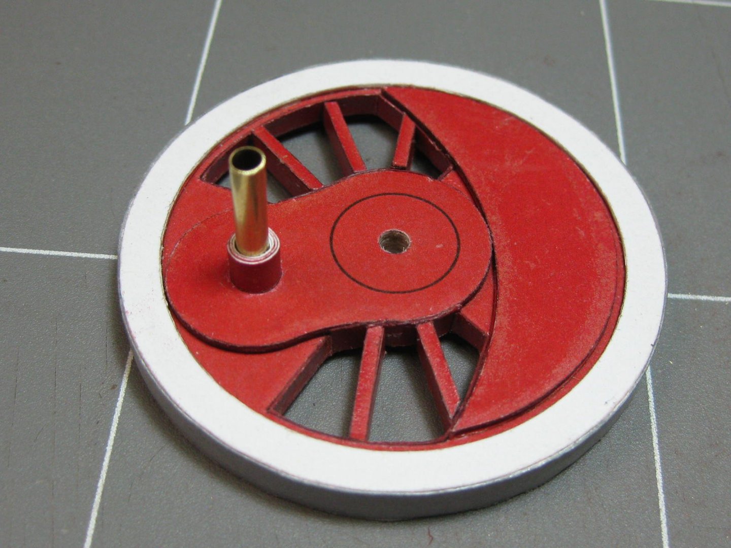
Hi all, thanks to all those who have commented and "liked" my build so far. My eyesight has been deteriorating lately, hopefully it's just a result of the chemotherapy I've been on and it will return to "normal" after it's over. I can still see well enough with my 8x Optivisor so the build can continue. The wheels. These took me a week to make. Some time ago I bought one of these Circle Cutters, but never had any success with it at the time I tried it. I decided to give it another go and see if I could work out how to actually use it, because there are a LOT of circles to cut - something like 8 or 10 for each of the 12 wheels I worked out the technique to make not only a success of it but to cut circles that were better than I could do by hand in MUCH less time. I'll put up a topic in "Tips and Tricks" a bit later to explain my method. Here's the result, and a pic of most of the parts needed : To assemble a wheel I made this simple jig. It's probably THE most useful jig I've ever made, turning out excellent results consistently : There are three different types of the main wheels - two Driving wheels (top), two middle wheels without flanges (left) and 8 of the rest (right) : I'm using the laser cut reinforcements as you can see. These are a bit different to the two wheels I made earlier, so I decided to scrap them and start over. The rim is 1mm narrower than the centre, and the spokes need to be sloped for them to fit properly. I achieved this by carefully cutting the rim off one disc and shaving the spokes down to zero thickness at the outer end. The wheel in the pic is one of the smaller ones which I made last. The large wheels have 12 spokes on most of them : Once all the discs were glued together I sanded the edge flat using a sanding stick with 150 grit paper : Then I glued the main edging on, followed by the rear flange on those that had one. There was no edging for the thinner flange, so I printed up some matching grey colour, cut it into 1.5mm strips and glued them on. It looks better than just painting them : All the large wheels completed : I modified my jig for the smaller wheels, as they only had a centre hole : Last job was to clean up the centre hole so that they turned freely on the axles. I used a small diamond coated round file : All the wheels. Most of them still need a spacer and wire for the crank : Danny
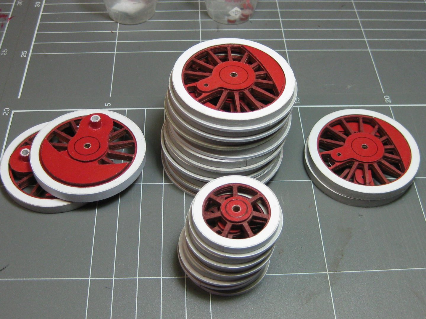

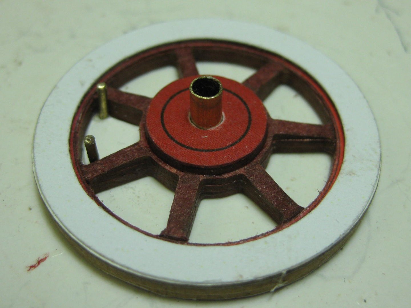


- 150 replies
-
- 18
-
-
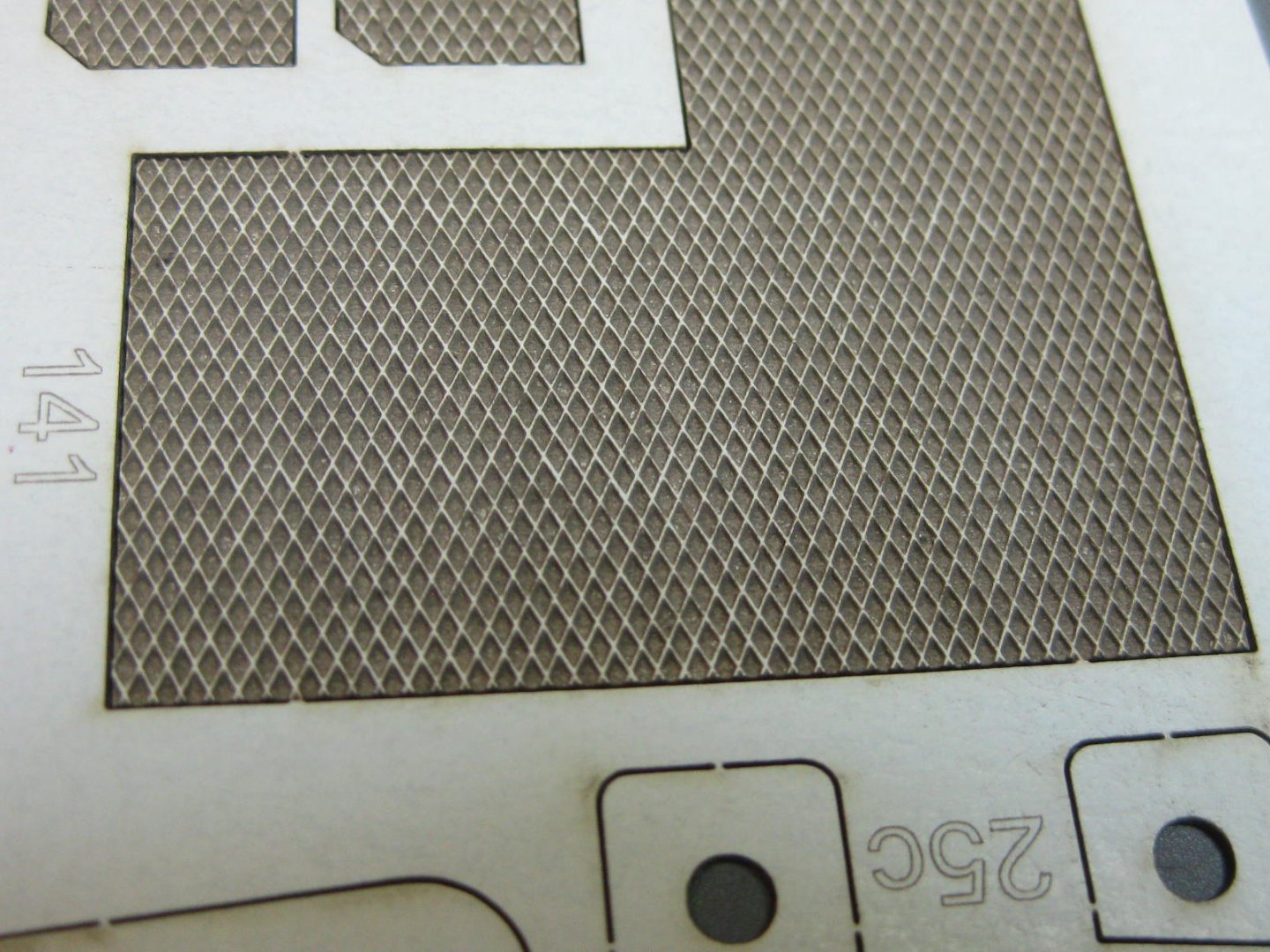
It's not just an EFFECT Tom, it really is cut halfway through the card. Welcome to my build Moab, I hope you enjoy the ride . Michael, I'm using a Craft Glue. It's a PVA that is acid free, very similar to your "normal" white wood glue. I use a very small amount of CA on occasion to strengthen the edge of delicate paper parts, and to glue metal-to-metal or metal-to-paper when needed. Danny
-
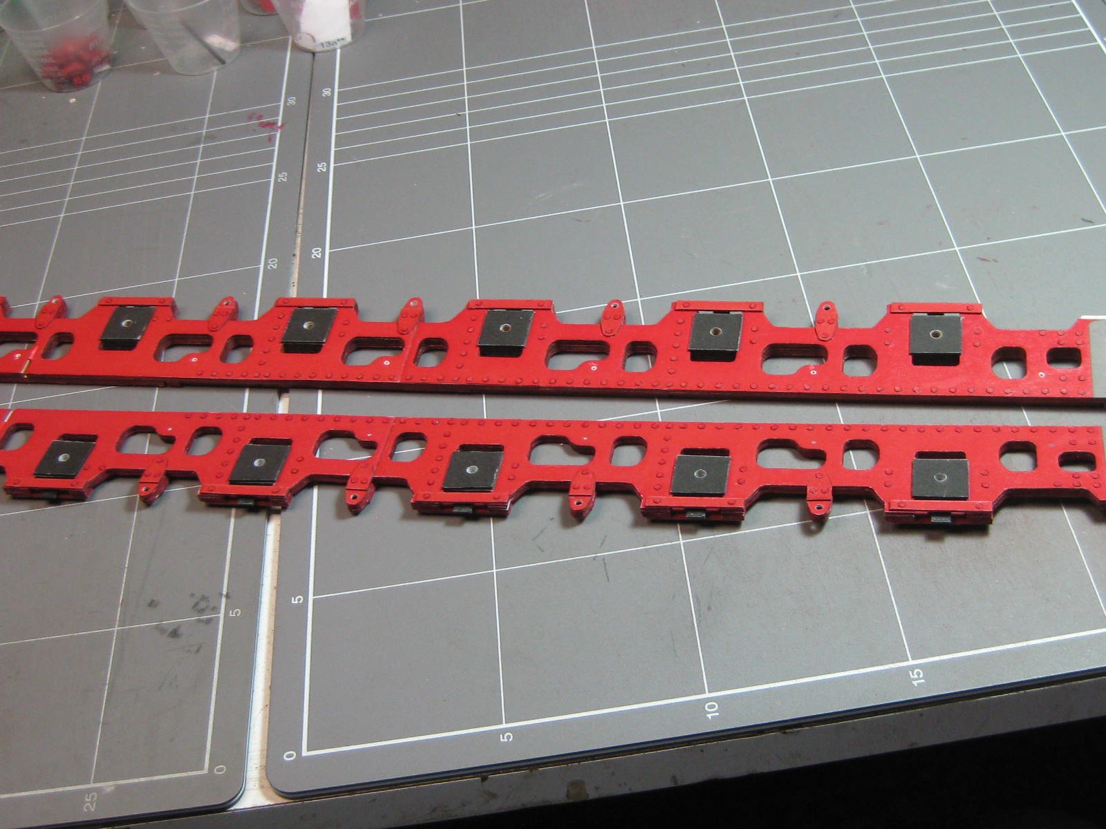
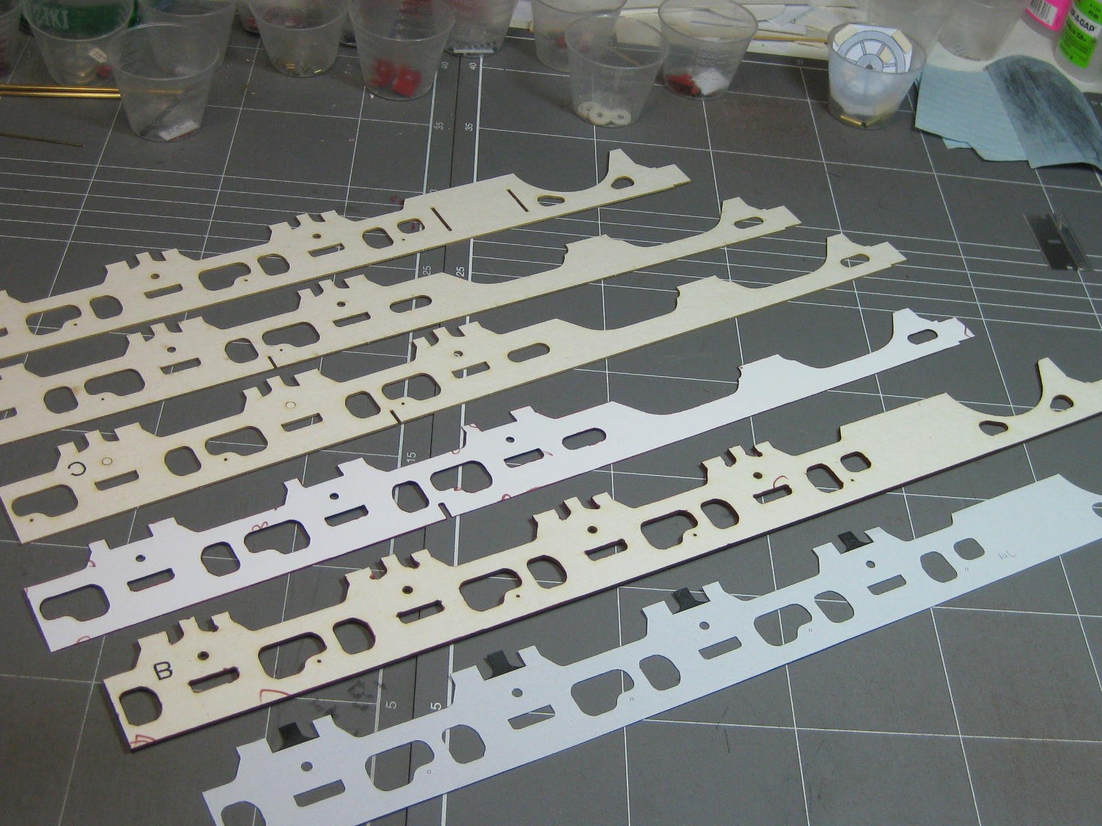
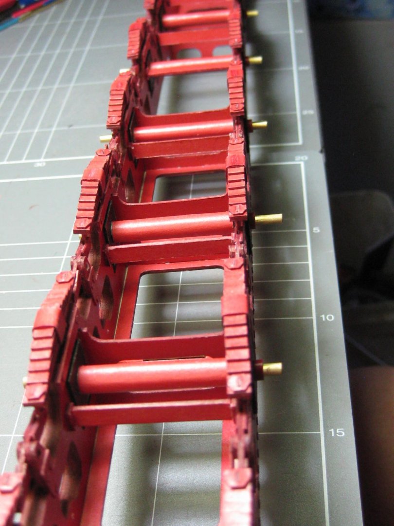
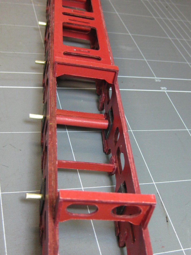
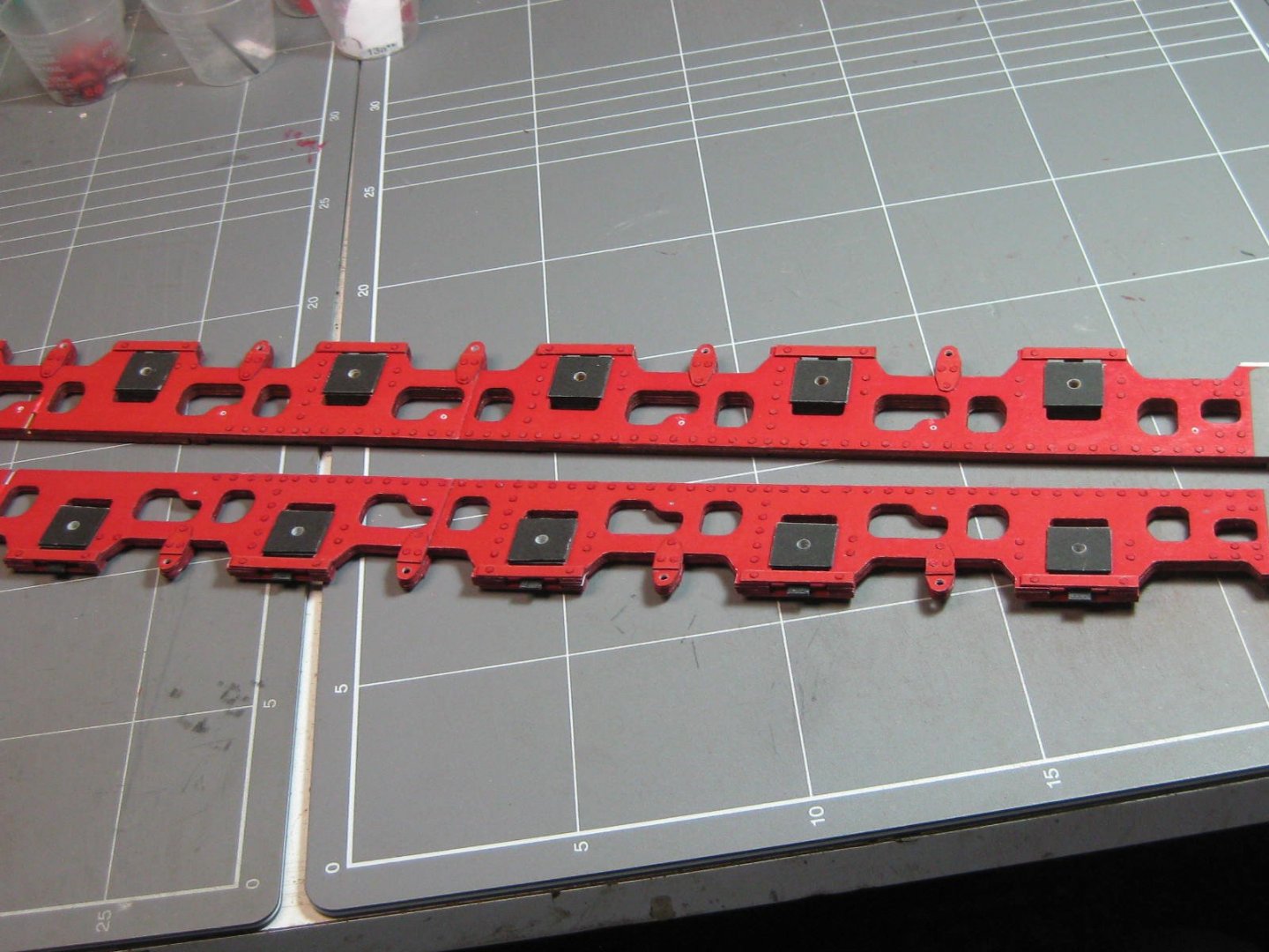
I've glued up the complete main frames. Very little trimming or adjusting was necessary, and I'm more than happy with the results. Especially considering all the dramas I had to get to this point . Now to make 16 more wheels, see you all again in a week or so : Danny

- 150 replies
-
- 24
-
-
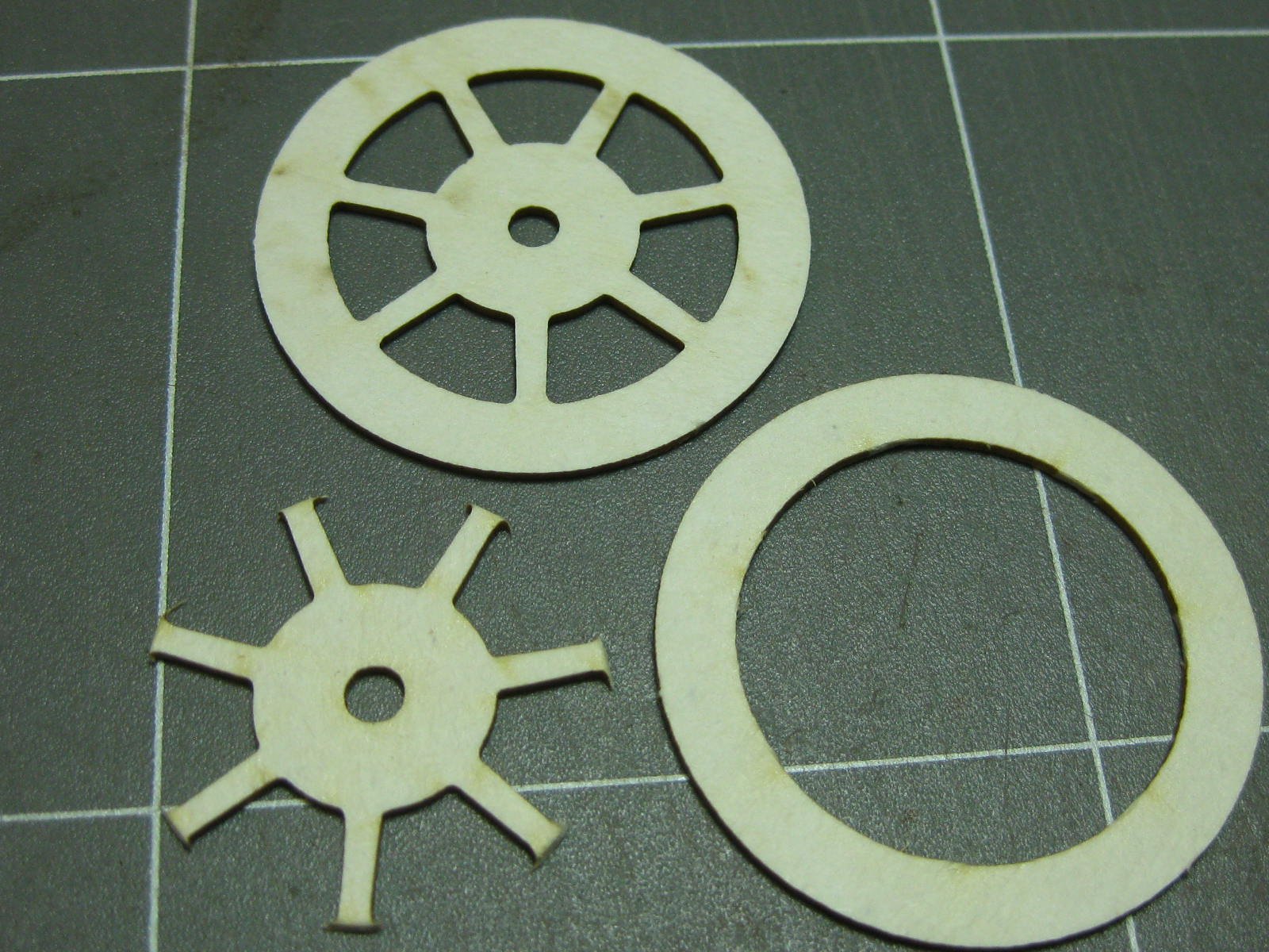
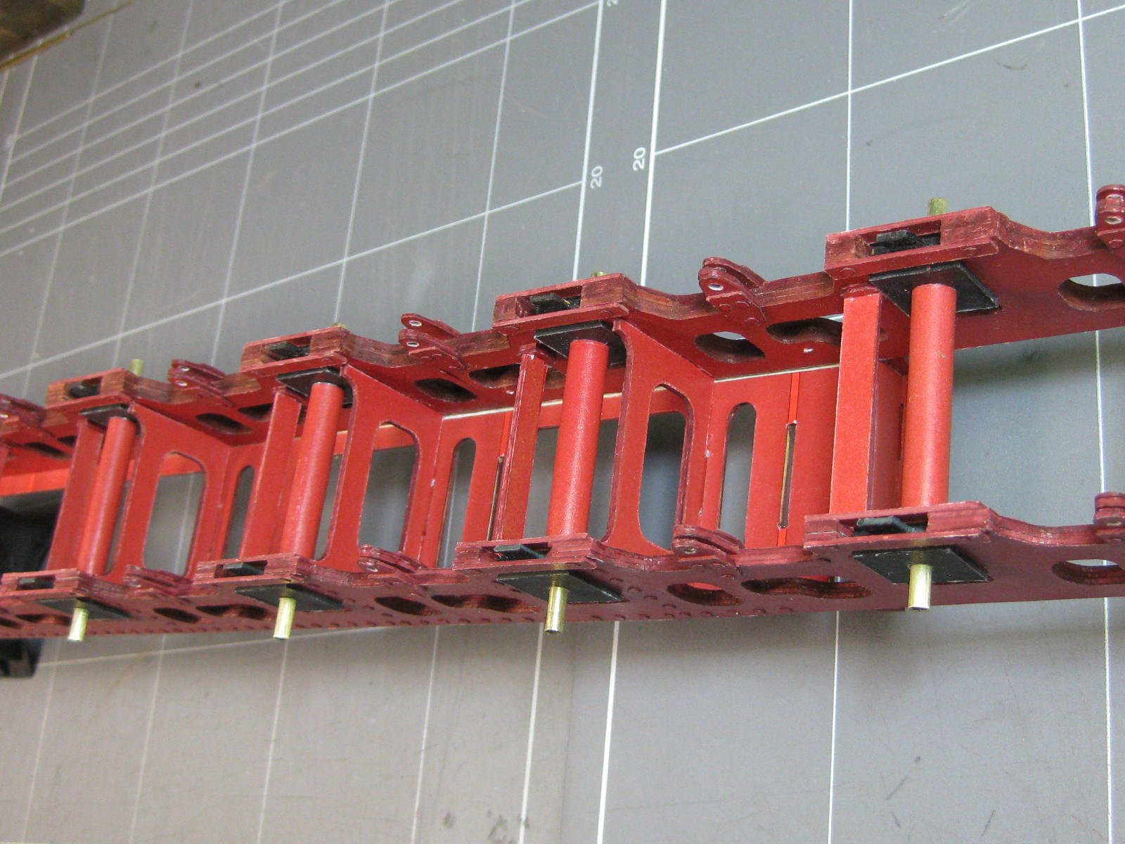
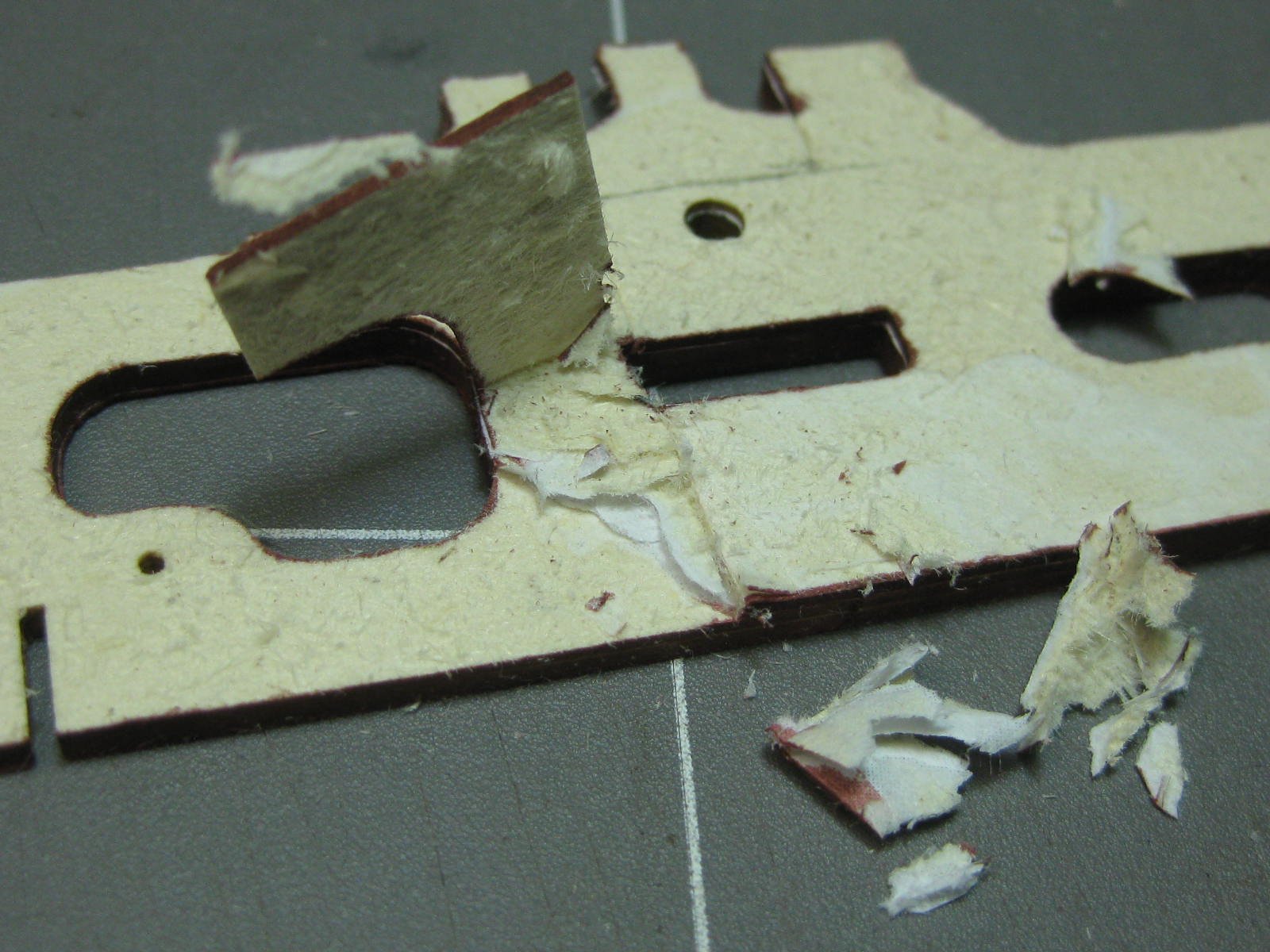
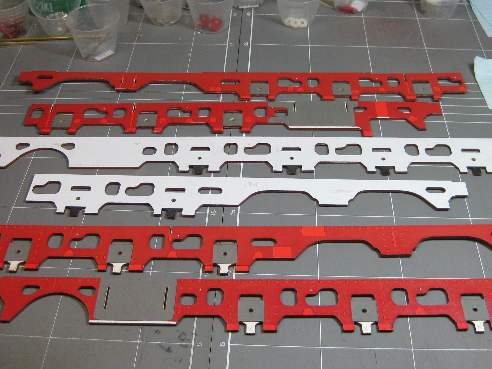
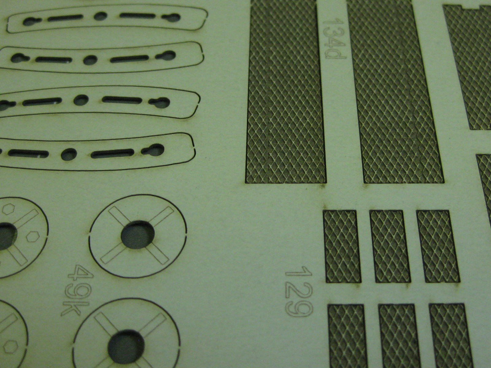
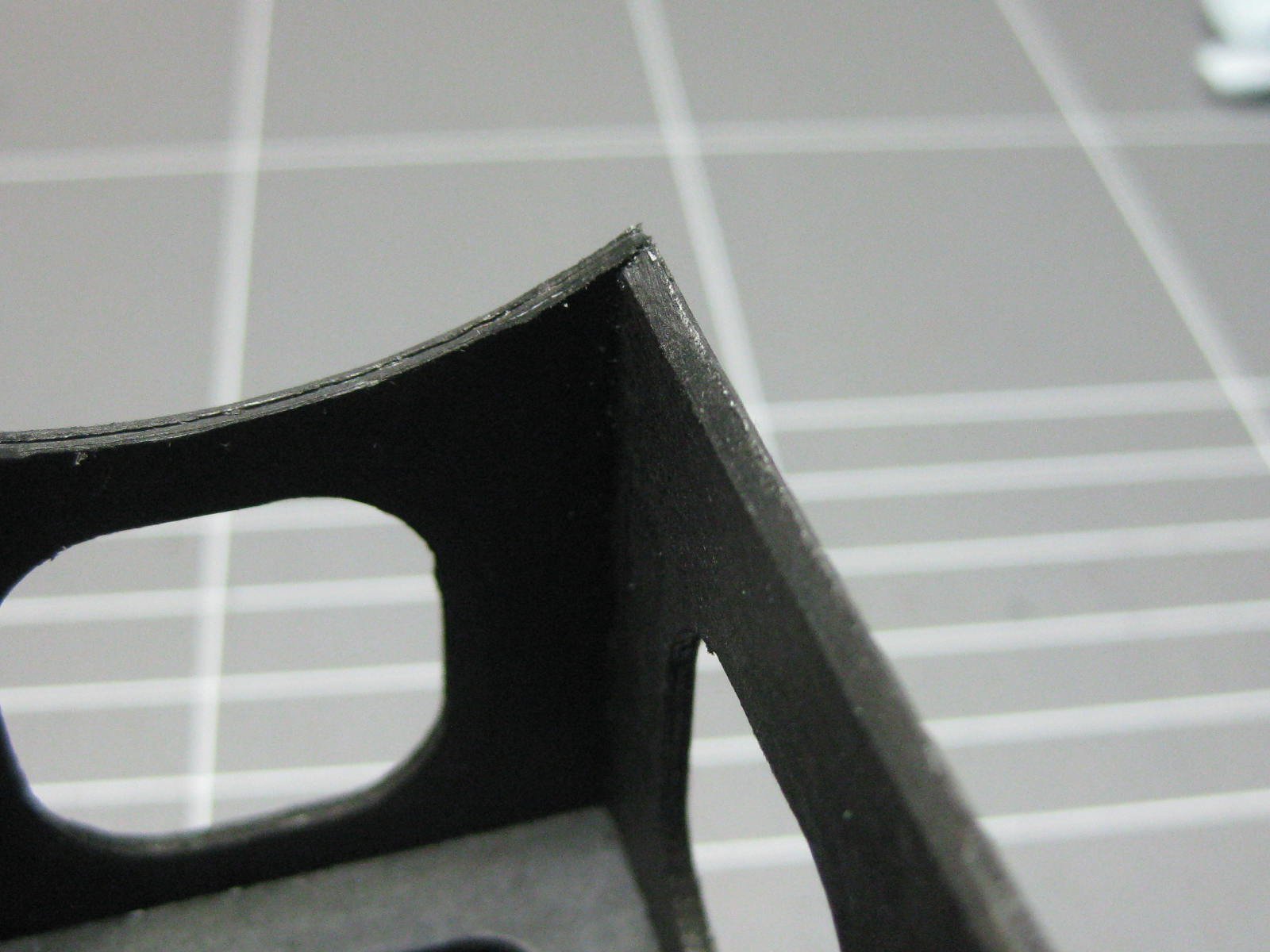
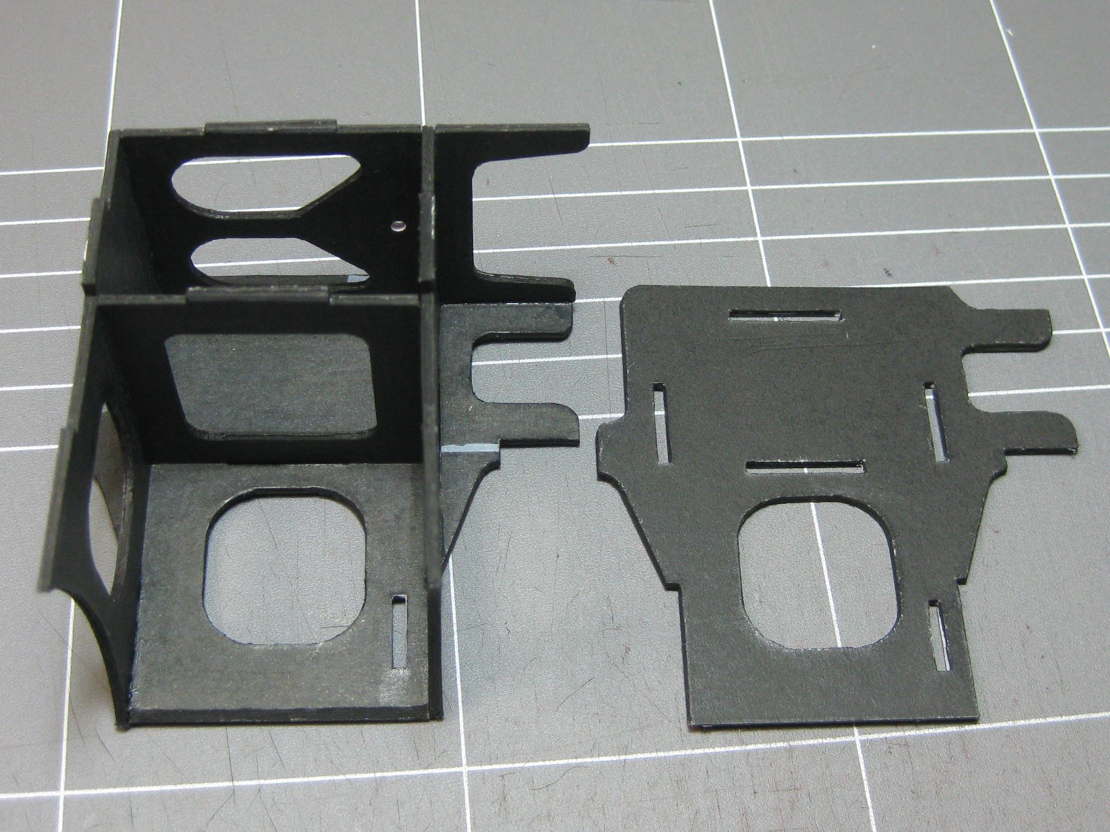
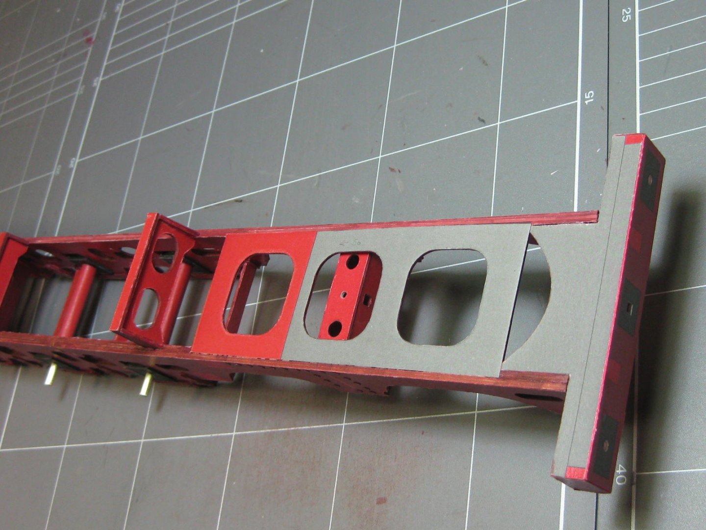
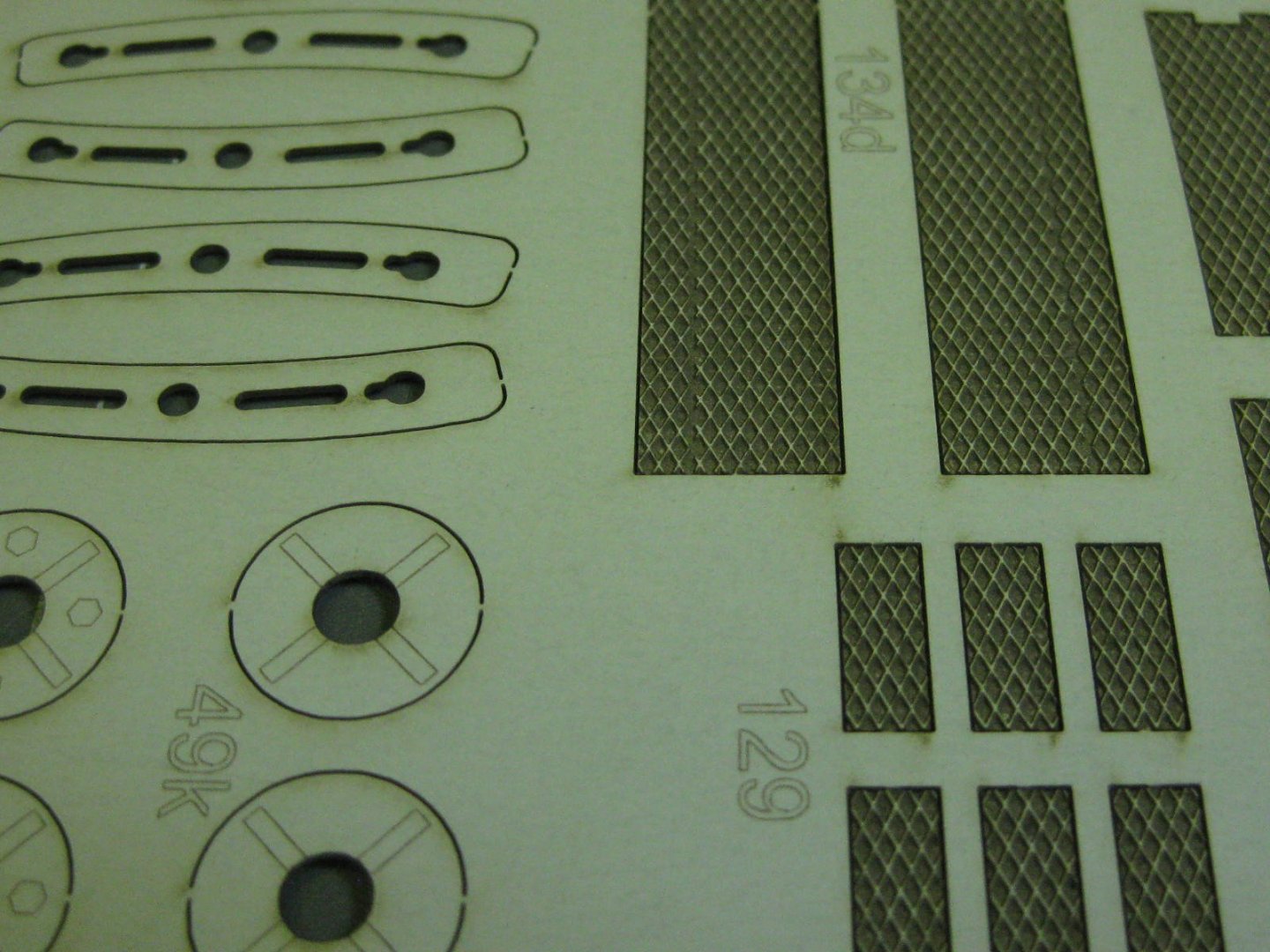
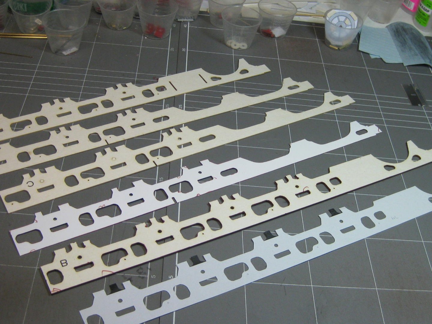
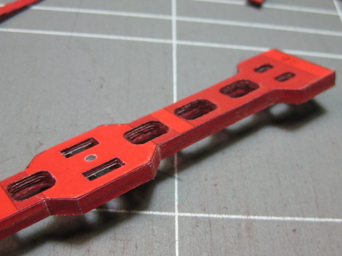
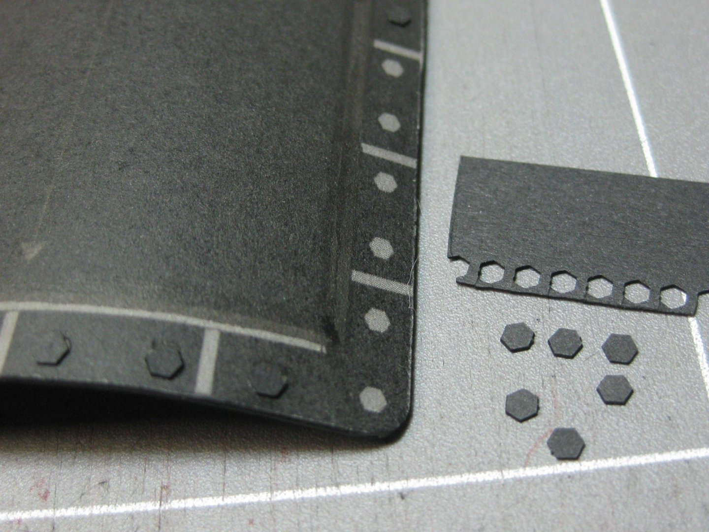
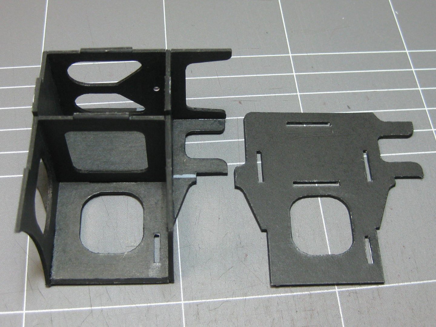
The laser-cut parts arrived just after I put up the previous post, so after sorting and filing the 10 sheets into my A3 folder I took a look at them. The laser cutting is about the best I've seen so far - the edges on even the 1mm thick card pieces are perfectly square and the cut itself is VERY fine. All but the larger pieces needed no little "tags" to hold them in the sheets, so that saves a lot of cleaning up . Here are a couple of examples in the 0.5mm thick sheet of some diamond mesh cut precisely half-way through - there aren't even any burn marks on the back side : Now that I have them I immediately got started on the right-side frame. I glued all the previously cut coloured pieces to the card and started gluing the sections together : That's when I discovered I'd made a terrible mistake. In my haste to get on with it I'd actually glued BOTH left and right sides to each piece, making them all 1mm too thick . This would have resulted in the side being 6mm thick instead of 3mm like the left side frame. What to do? I decided to toss the middle section altogether and trim the inner pieces down to 1mm thick. This took me about 3 hours to accomplish : All good now, the right side is done. A check with my digital vernier shows that the completed side finished up within 0.05mm tolerance - I'll live with that : Danny


- 150 replies
-
- 16
-
-
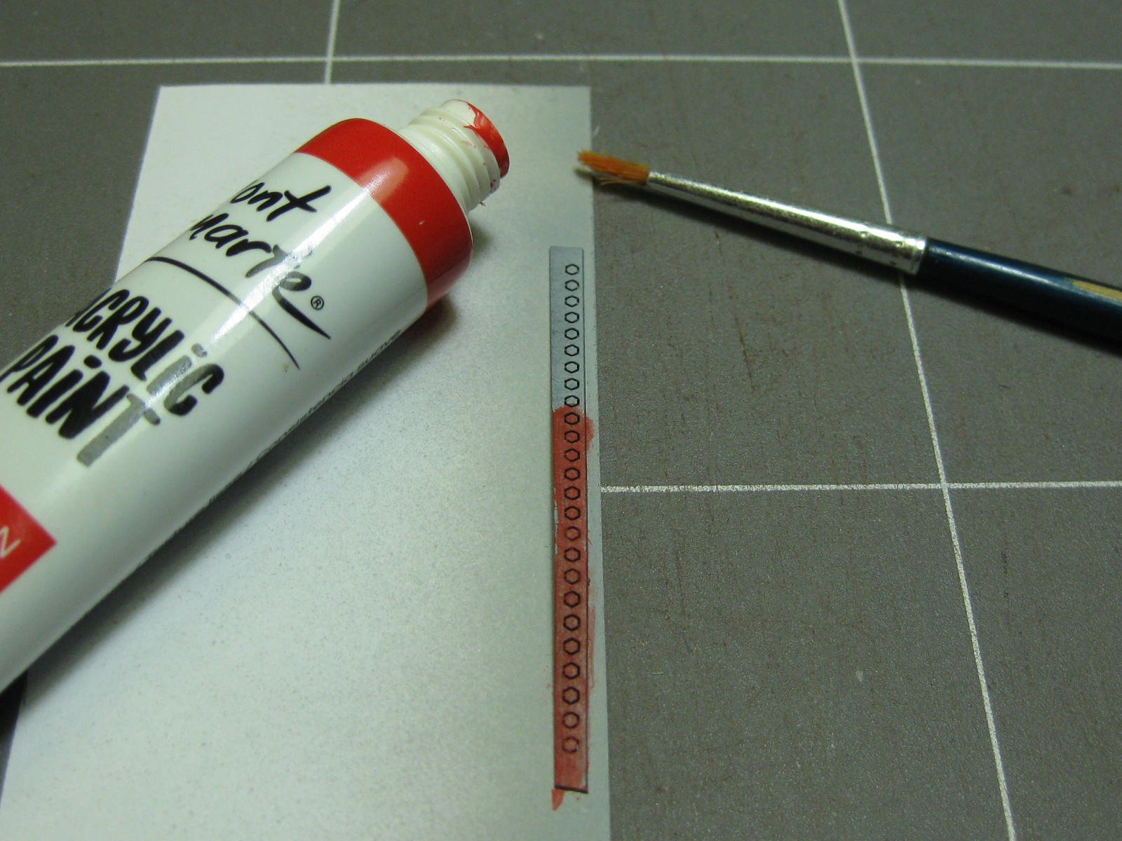
Actually Ken, until I glued the arm to the cylinder clevis it DID all work . Still no laser-cut stuff, so I made up the main brake cylinder assembly : I needed a few more red bolt heads, so I used this method to paint some primed (formerly black) laser-cut ones : Danny

- 150 replies
-
- 14
-
-
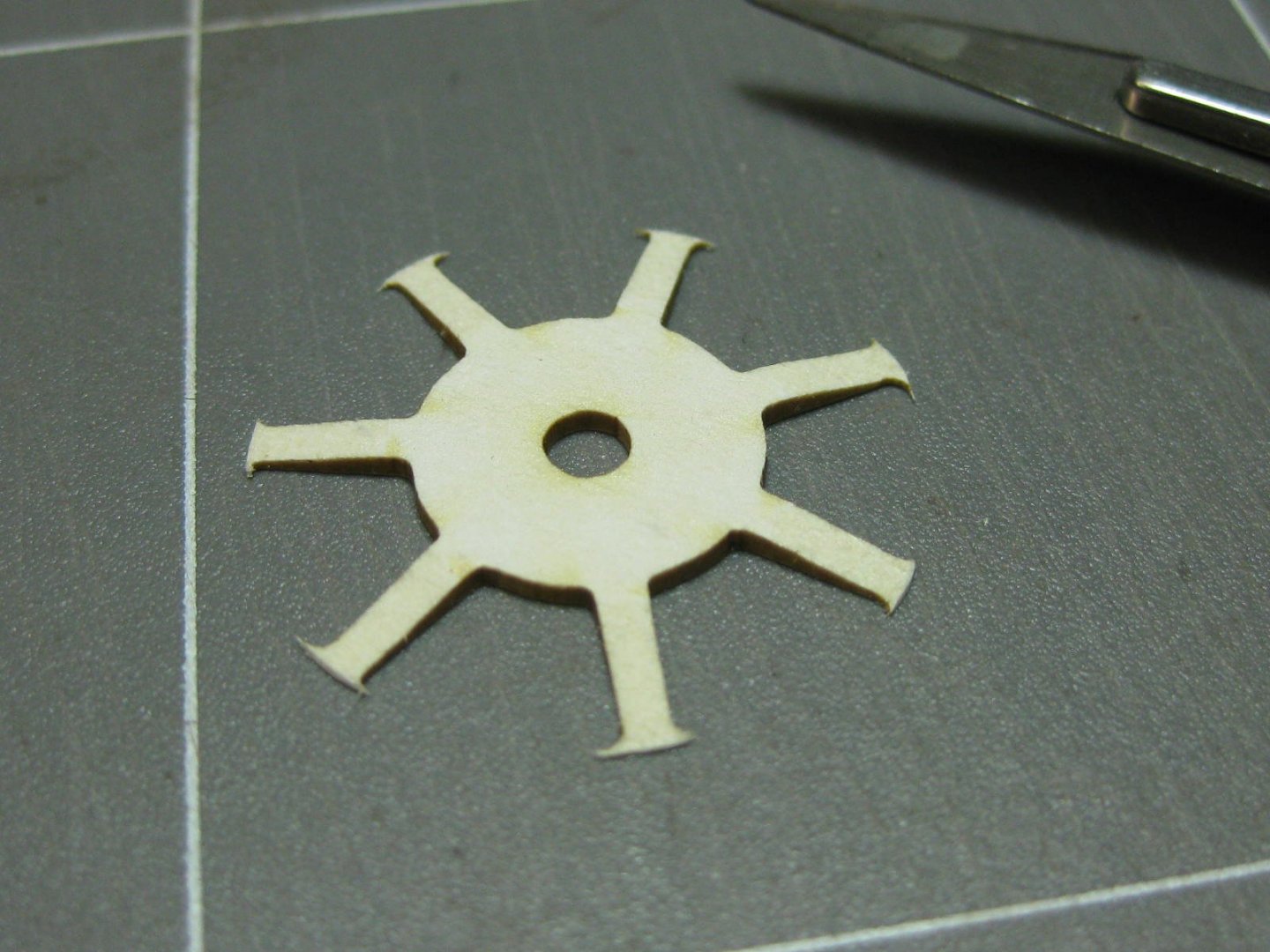
Thank you Mark, Caroline and Ken . The smaller bogie wheels have fewer parts than the main ones, so making one didn't take all that long : The kit supplied a template for gluing the spokes to the rims, there are 3 of these - one for the bogie wheels and two for the drive wheels as two of those are different to the other 10. I turned the templates into jigs by mounting the thin paper to heavy card and adding some stops where needed to make assembly of the others much easier later on : The finished wheel : I needed the wheel to align the brakes properly. Here are some of the parts for the mechanism : One brake completed : Danny


- 150 replies
-
- 24
-
-
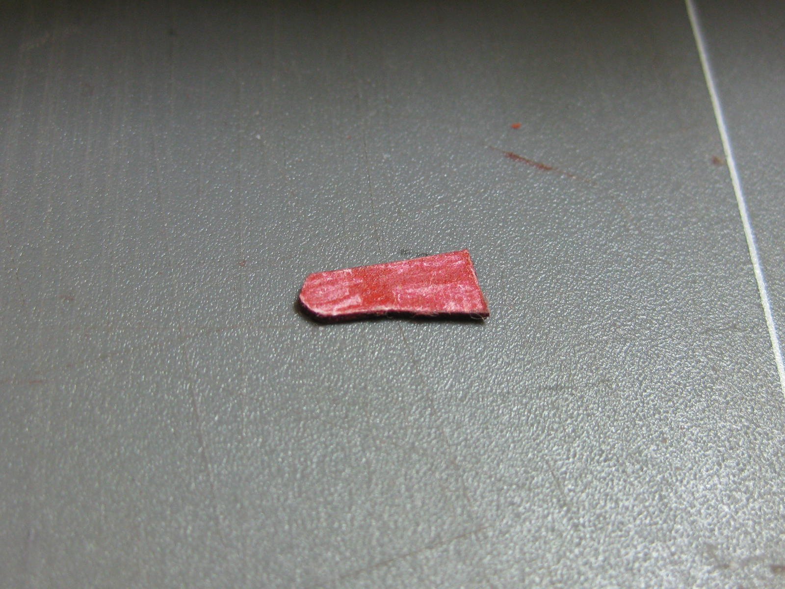
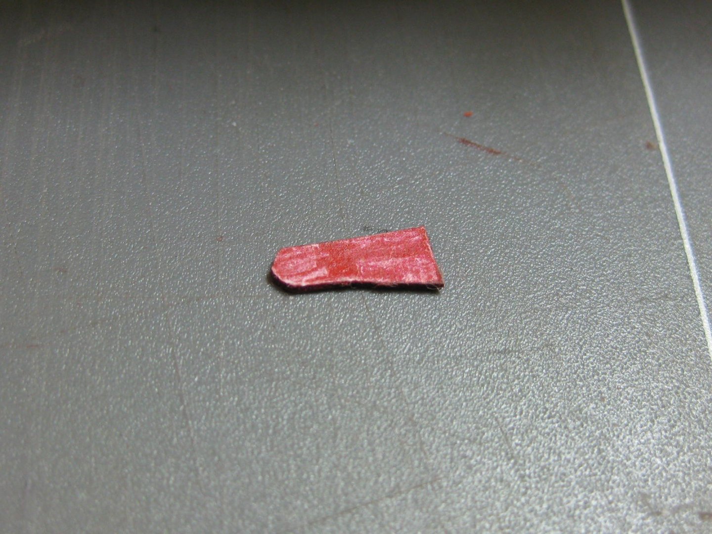
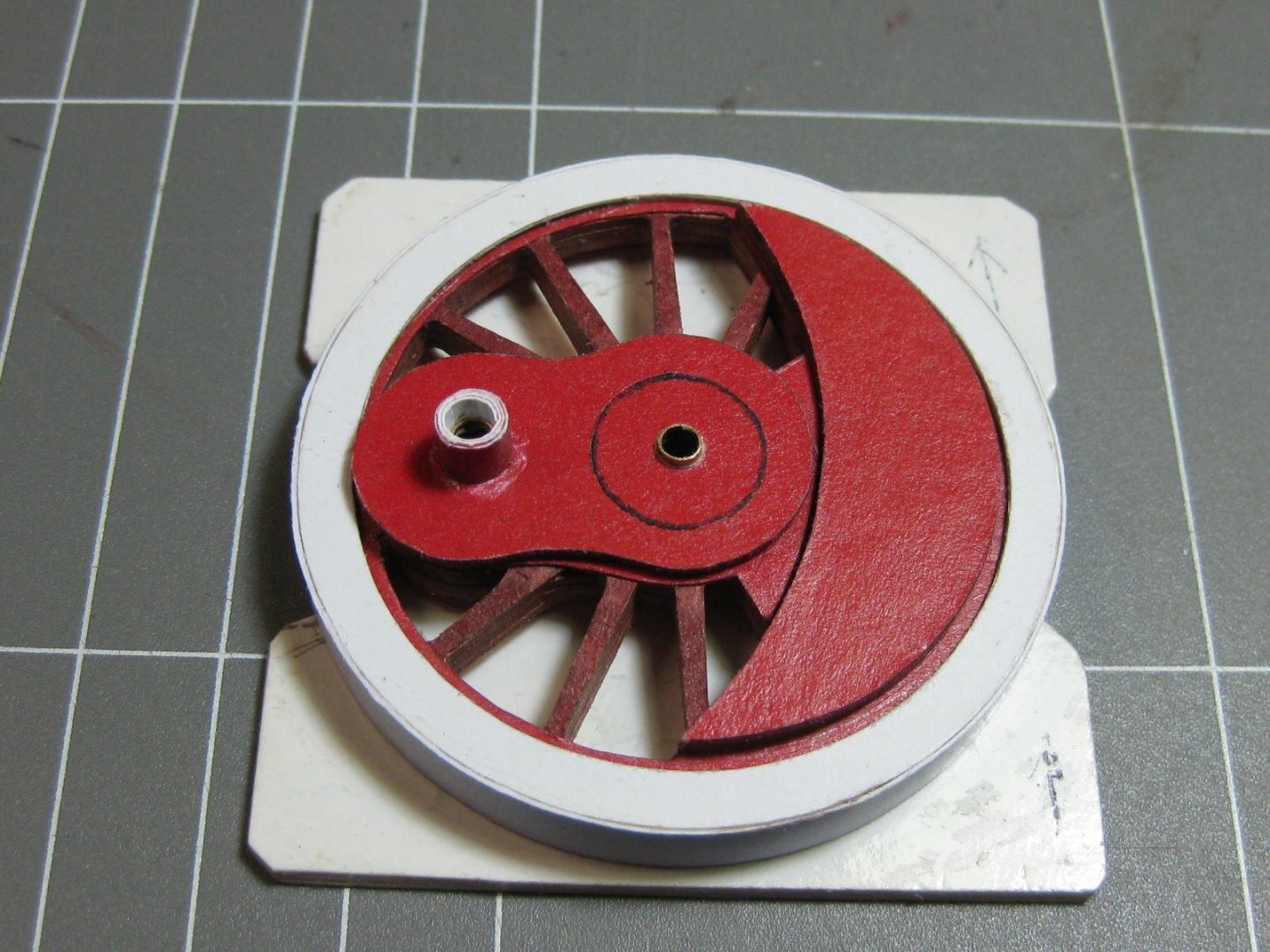
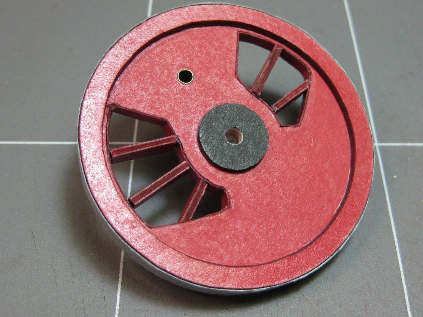
I think I've worked out why it's taken Stephan a couple of years to get a little bit past this stage - the wheels . One wheel took me 12 hours to make - 17 more to go. At this stage I'm only making one large and one small wheel, as I need to check a few measurements before continuing on with the brake assemblies, and my laser-cut frames and wheels are still on the way from Poland. The parts for one of the driving wheels. Nearly every part needed to be laminated to 1mm thick card. I'd ordered 10 sheets of 0.5mm and 10 of 1mm card from GPM two weeks ago, it arrived yesterday (pretty good for them). This card is MUCH easier to cut than the far denser card I'd bought from Officeworks : One wheel finished : You may notice that I'd scraped the gluing surface of one of the red discs. Most of the red parts have a coating on them, probably clear lacquer, which doesn't glue very well. Danny

- 150 replies
-
- 24
-
-
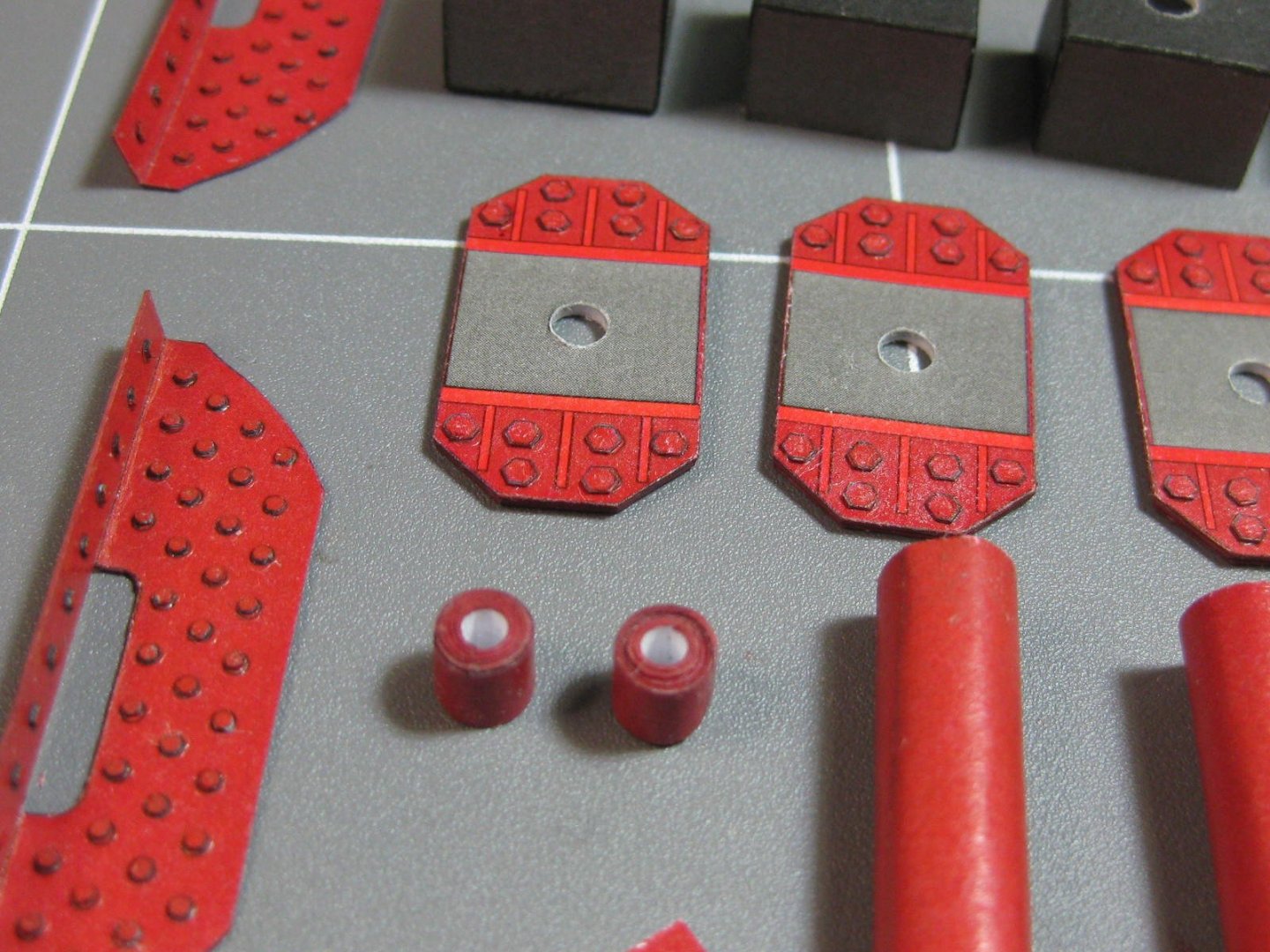
The rear bogie is much more complex. There's about a week of work involved in this. Once again a lot of rivets. I used the laser-cut ones for this, as cutting about 200 1mm diameter rivets was not an option. I pre-painted them before cutting them off the sheet. They were supplied in black, a thin coat of grey spray primer was applied first followed by artist's acrylics vermillion straight from the tube which was a very good match : Aligning each part was critical to the outcome. I used 2mm and 3mm tubing wherever I could to ensure that : The parts for the brake/suspension assembly frames : Fitting the brake/suspension frames to the main bogie frame : The completed rear bogie : Danny


- 150 replies
-
- 19
-
-
Major slackness on my part, as far as updating this log goes and not in the amount I've accomplished. Sorry about that, I hope the following couple of posts make up for that . The front bogie, which only has a pair of wheels attached. Not a lot of pics unfortunately, but the last one shows the completed unit ready for fitting to the main frame (when I finish that) : More in the next post, Danny.


- 150 replies
-
- 11
-
-
QUICK-FIND INDEXES to BUILD LOGS FOR KITS
Dan Vadas replied to Dan Vadas's topic in - Index of all kits by brand and subject
Not you, problem fixed . Danny -
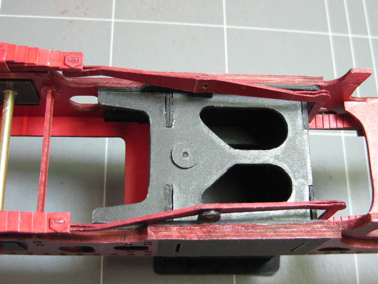
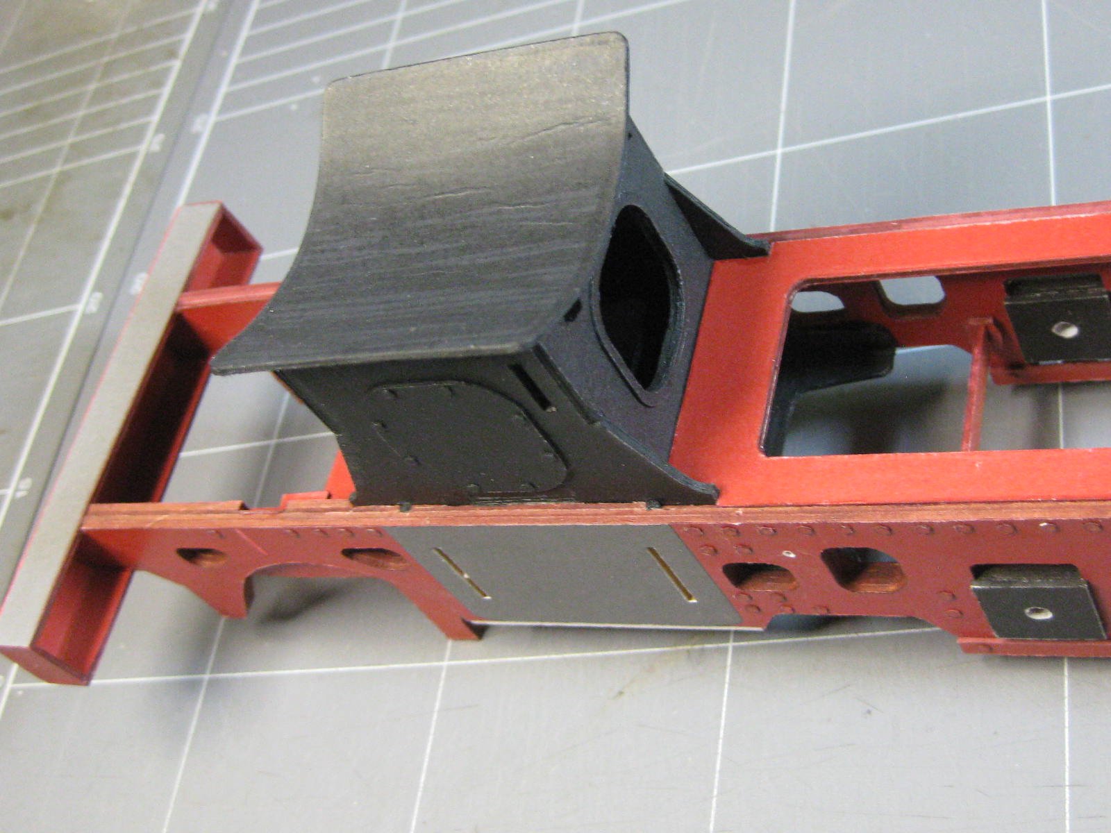
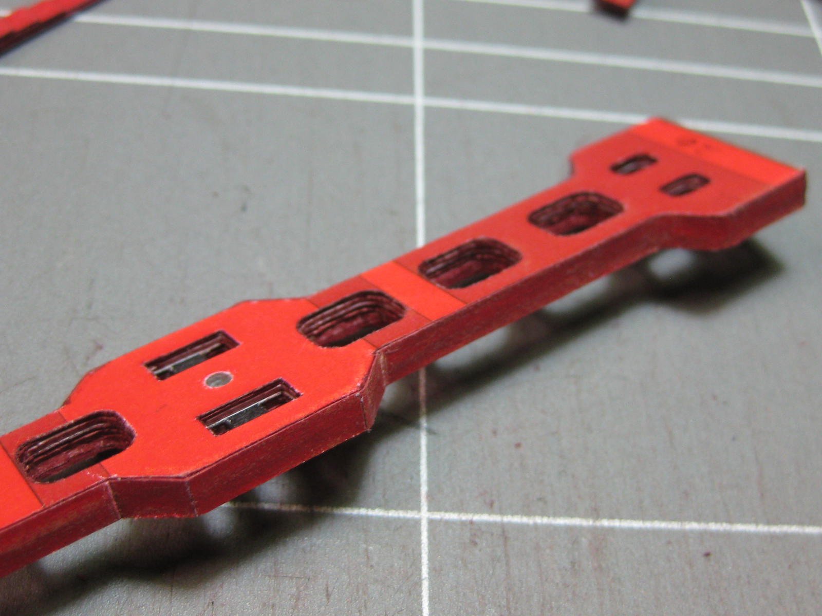
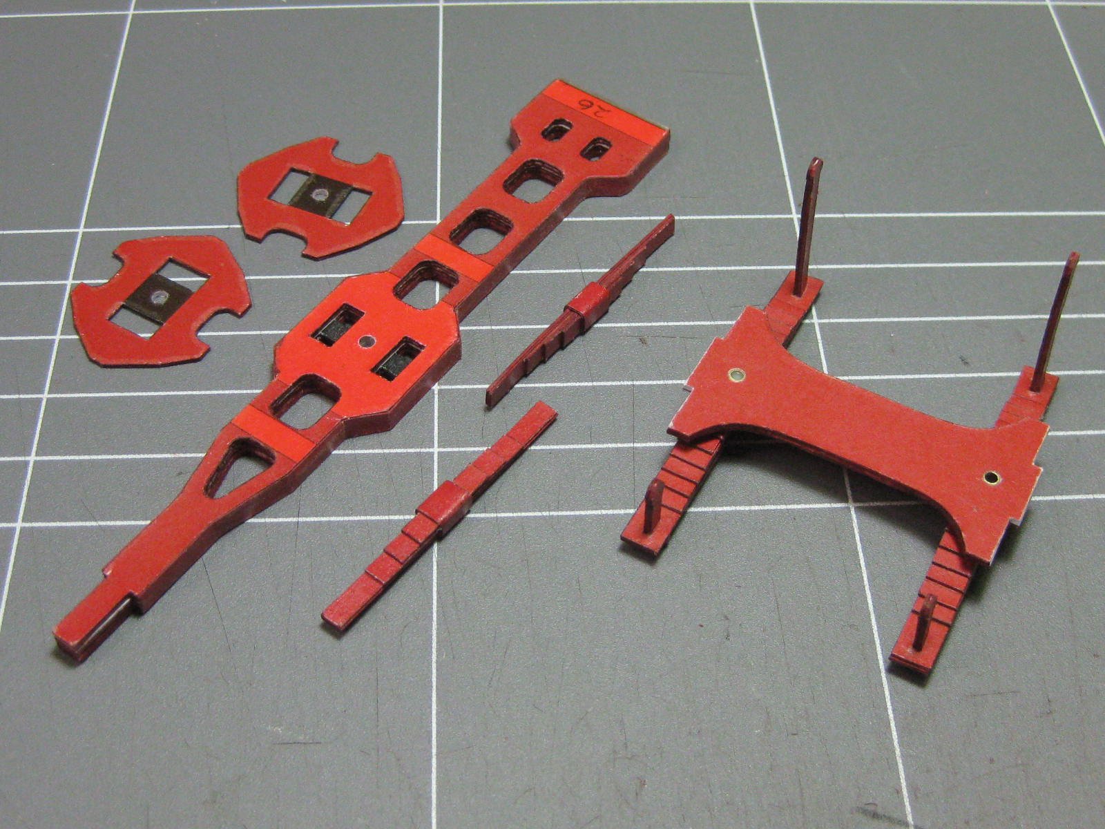
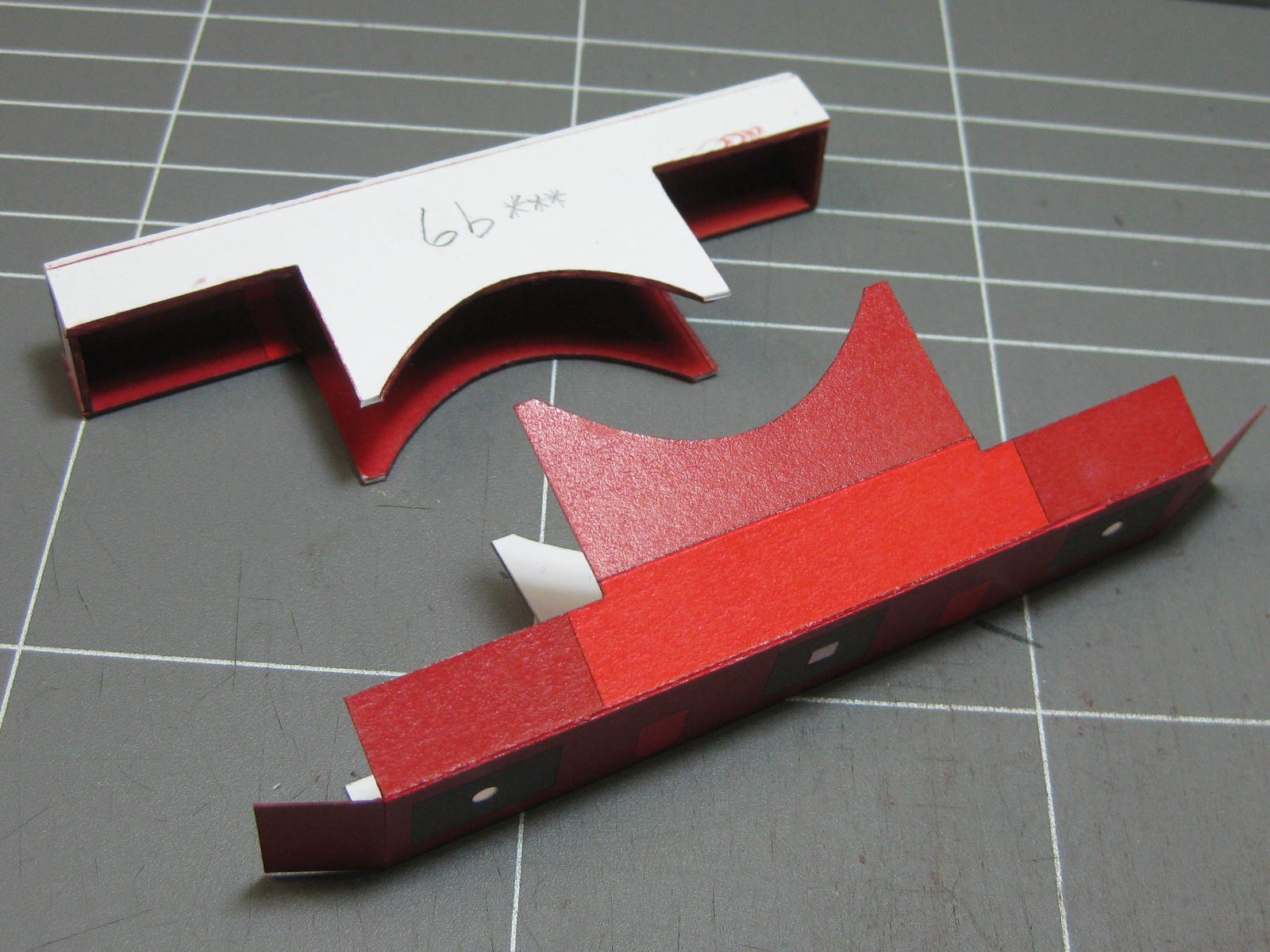
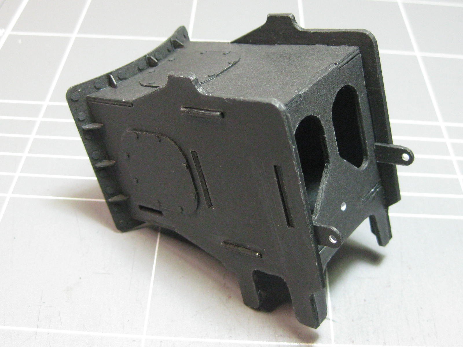
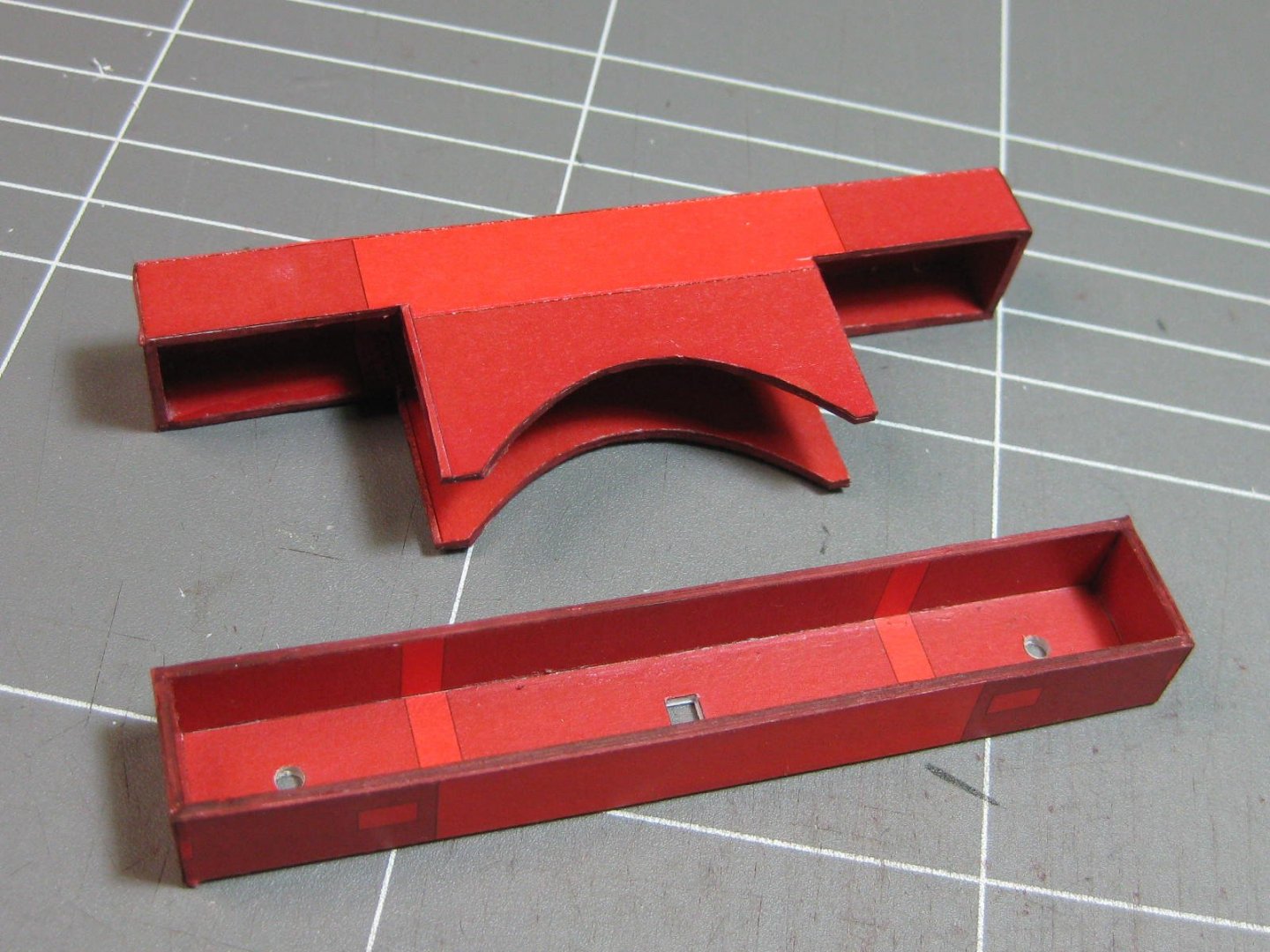
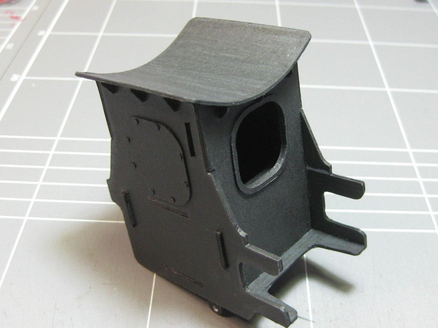
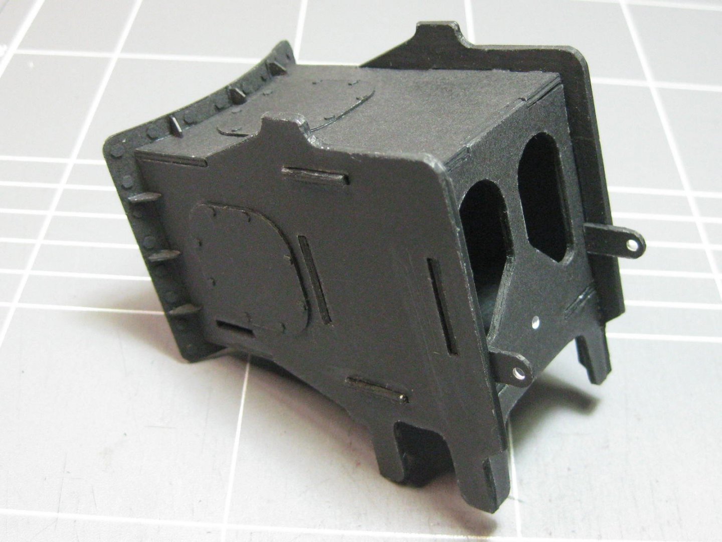
This assembly is the smoke box. A lot of laminating was needed, no doubt the laser-cut sheets (which are still in transit) would have had the middle supports included but I forged ahead with several layers of card. This assembly therefore took me three days to make, I'm quite happy with the results : A bevel needed to be cut for the "roof" section : The "roof" didn't fit very well - it was too short in one direction and too long in the other according to the glue markings despite the accuracy of the rest of the box. Apparently it's a problem with the kit design, as another builder (Stephan) found the same thing with his. I'd read his build log where he pointed out the mistake, so I was extra careful to align the box in case he hadn't, but came up with the same error. Hopefully there aren't too many more errors down the track, this one was quite easy to fix. I used the black laser-cut bolt heads this time instead of cutting my own : The tabs on the sides will be covered by the main frames later on. The two that extend out are used to align the box with the inside of the frames. Danny

- 150 replies
-
- 20
-
-
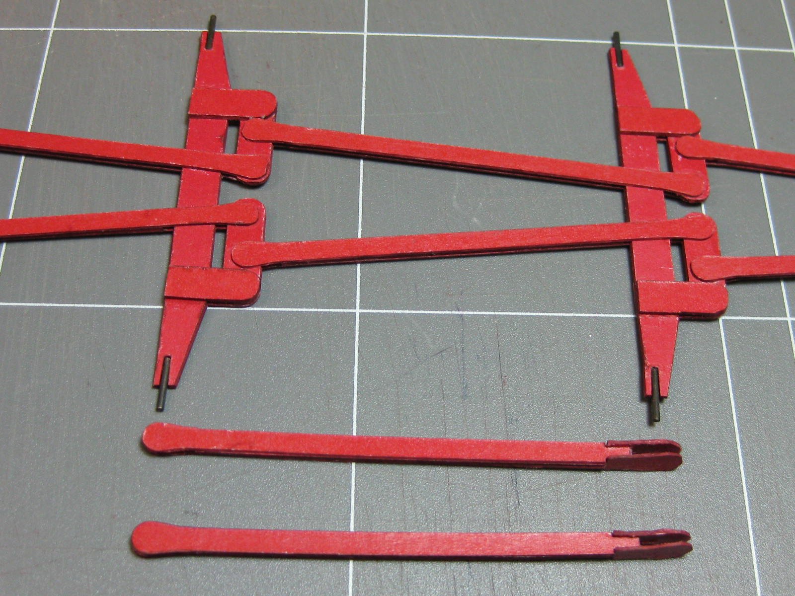
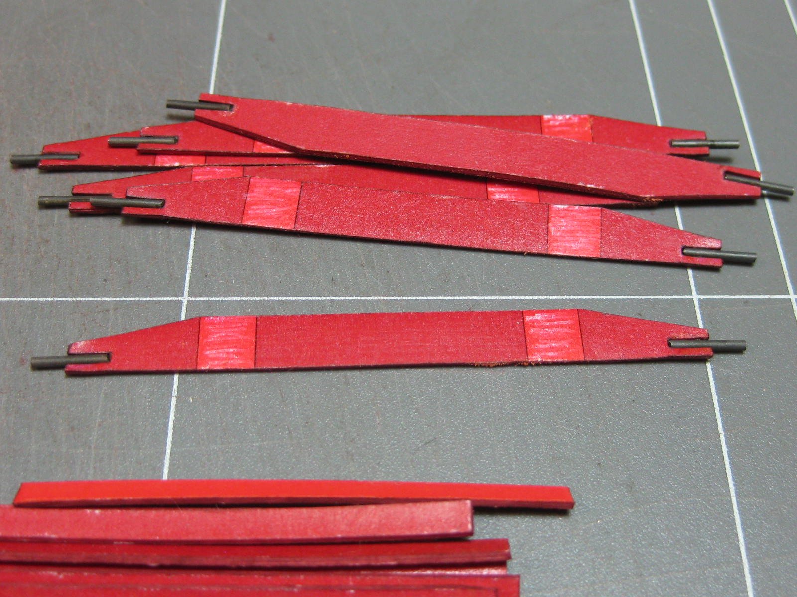
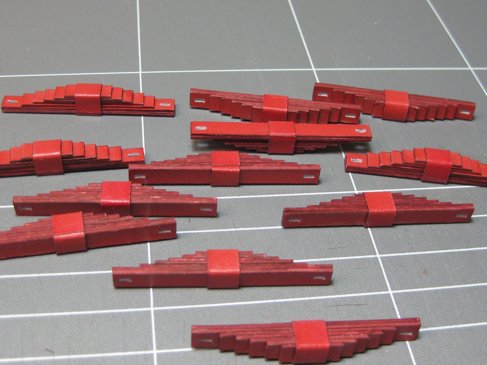
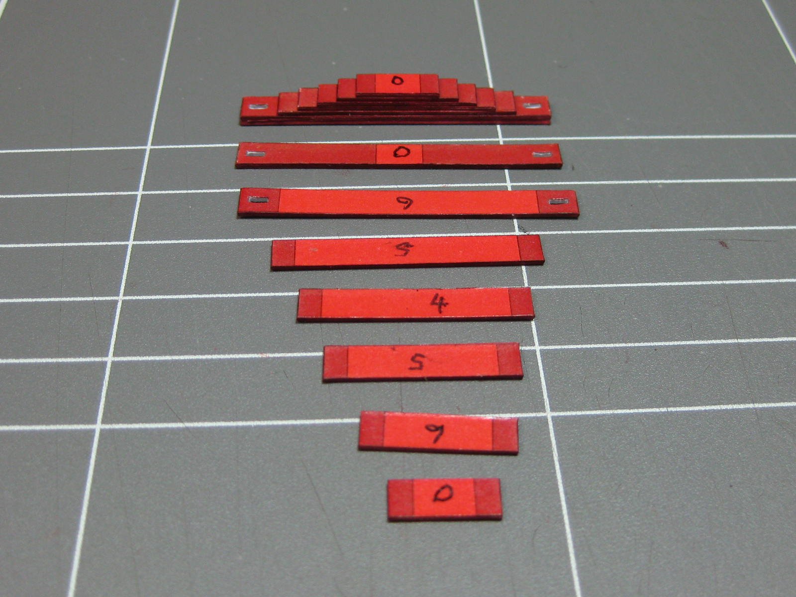
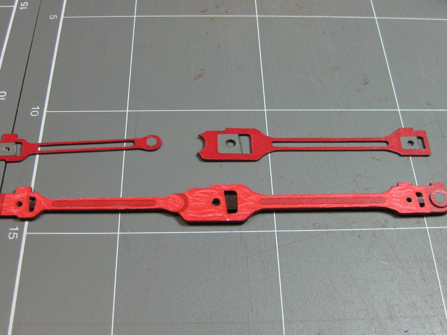
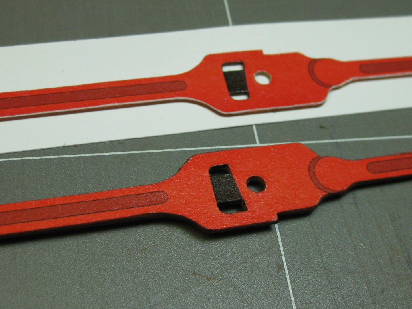
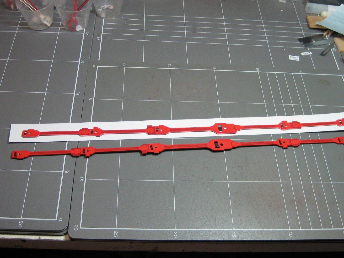
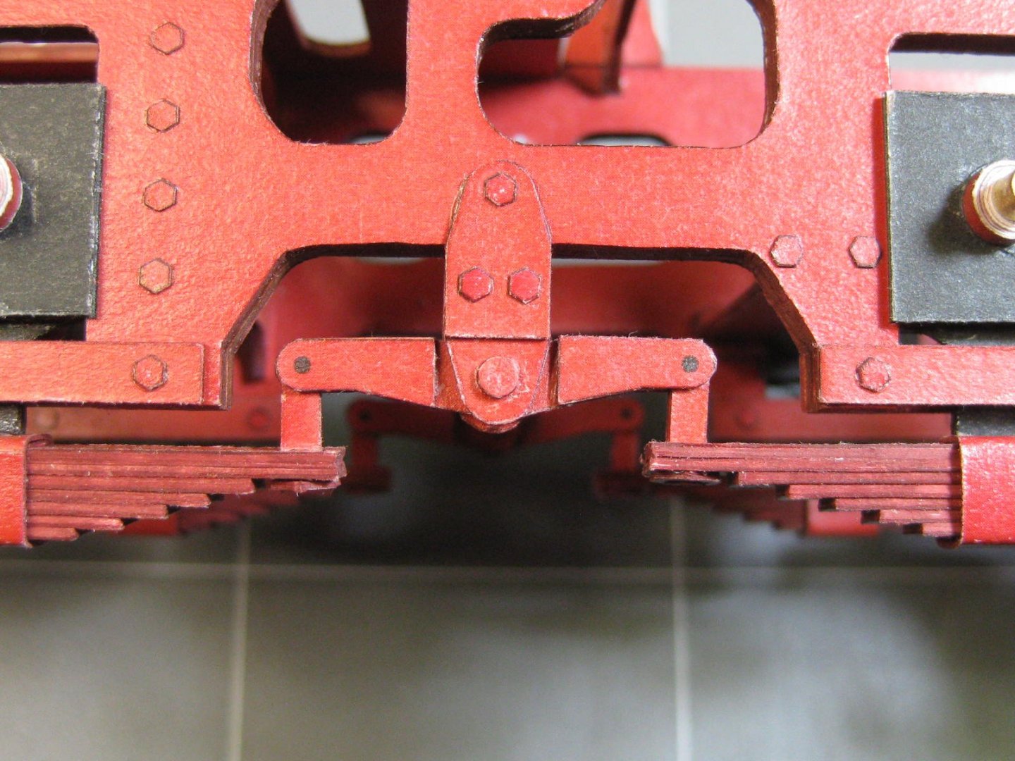
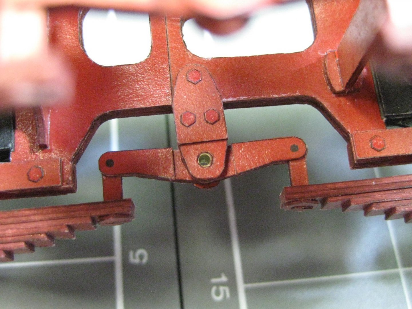
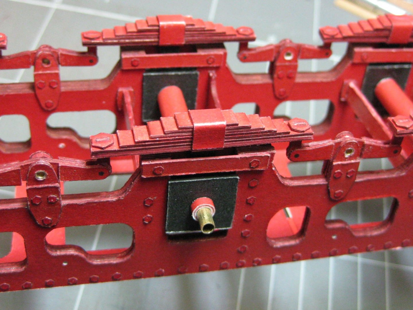
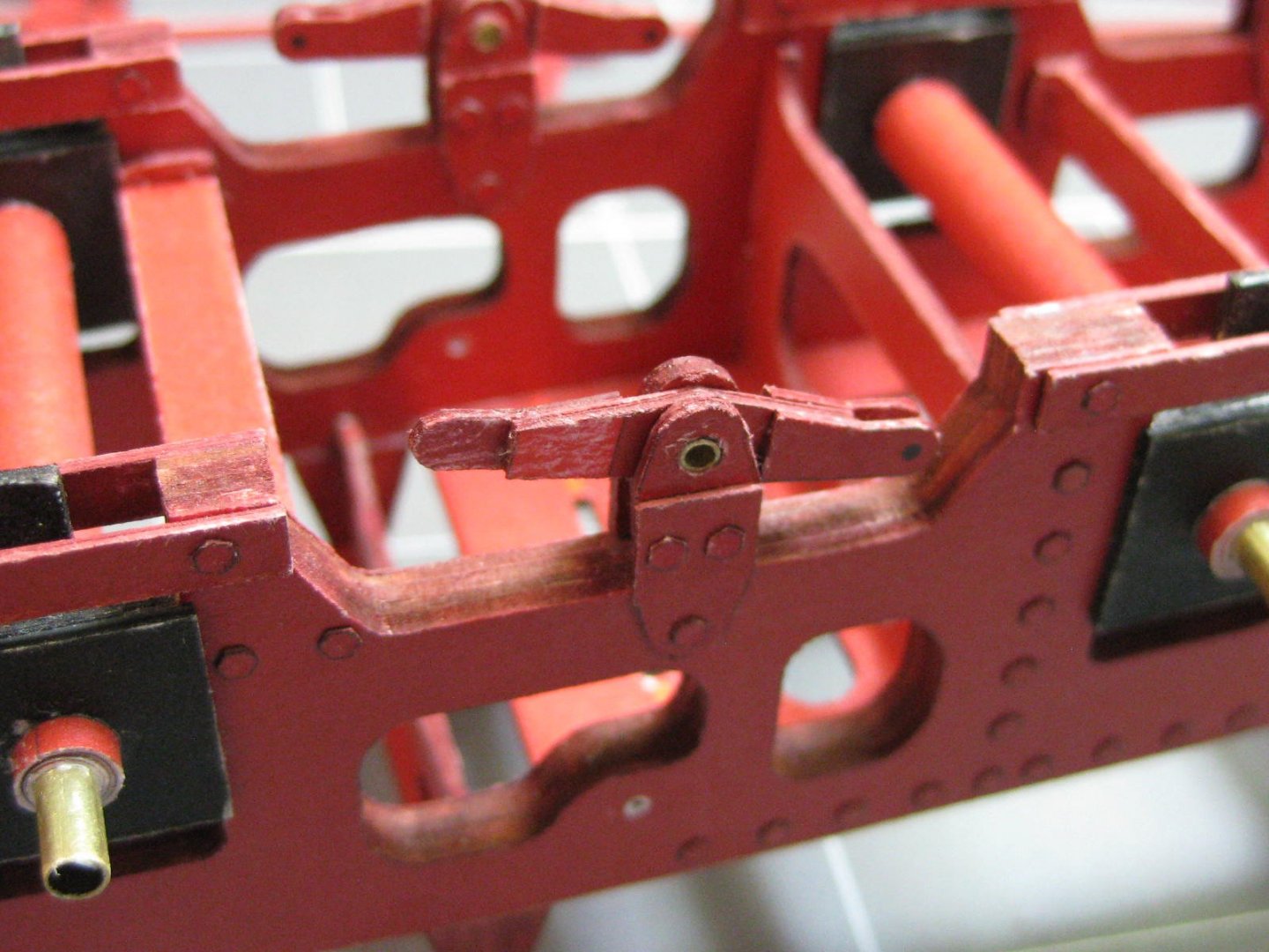
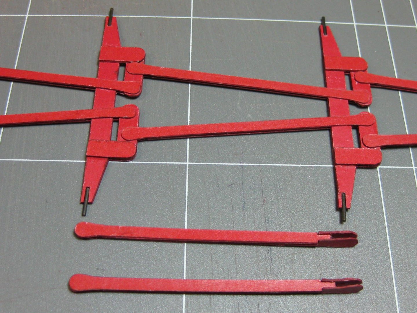
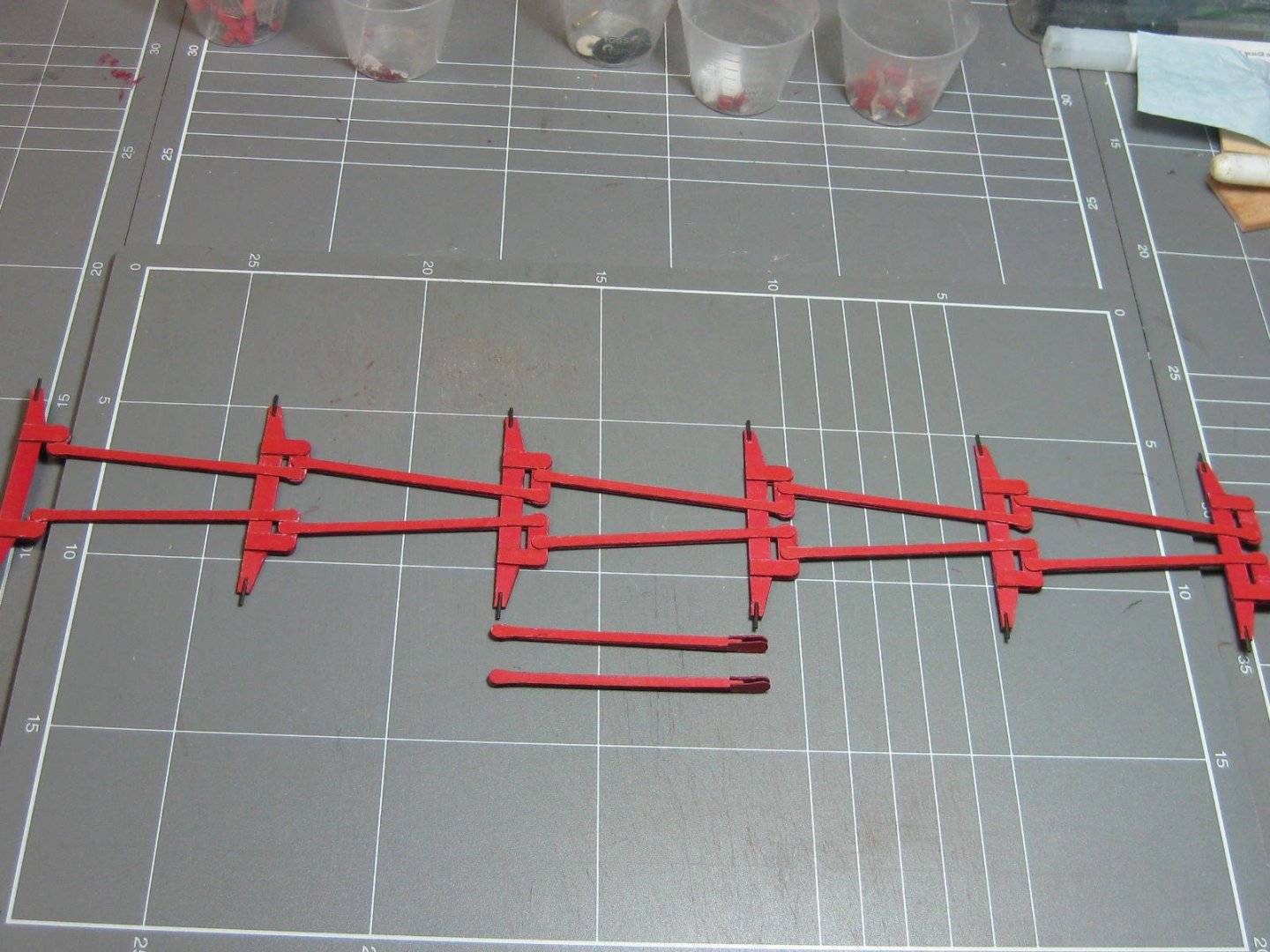
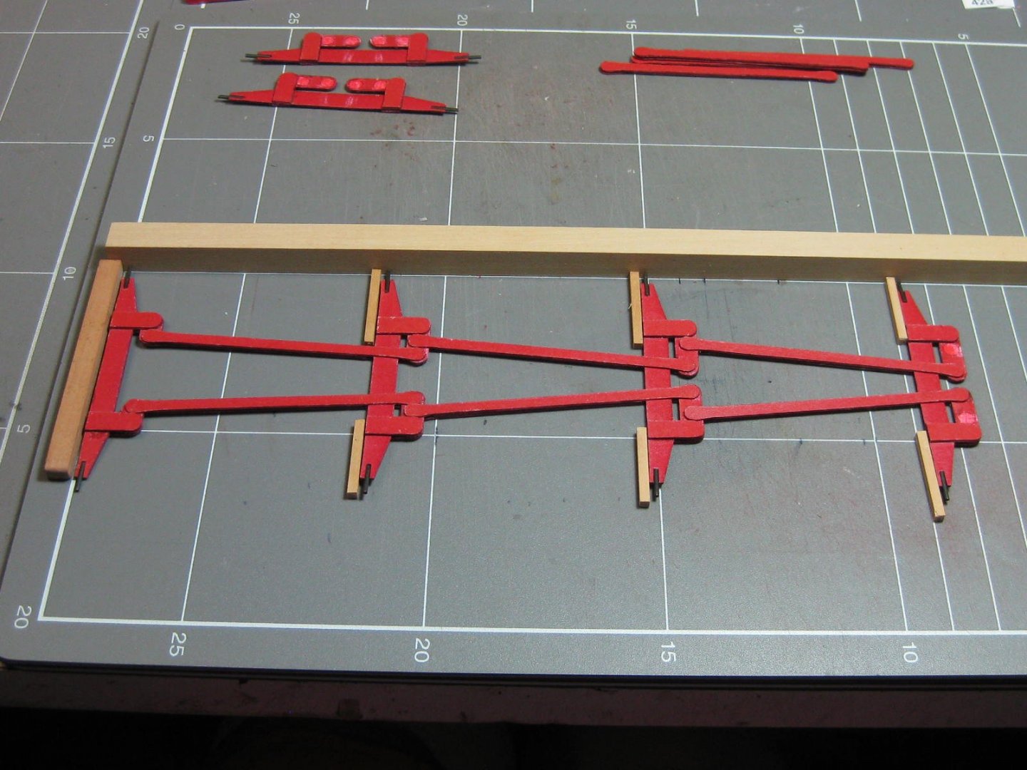
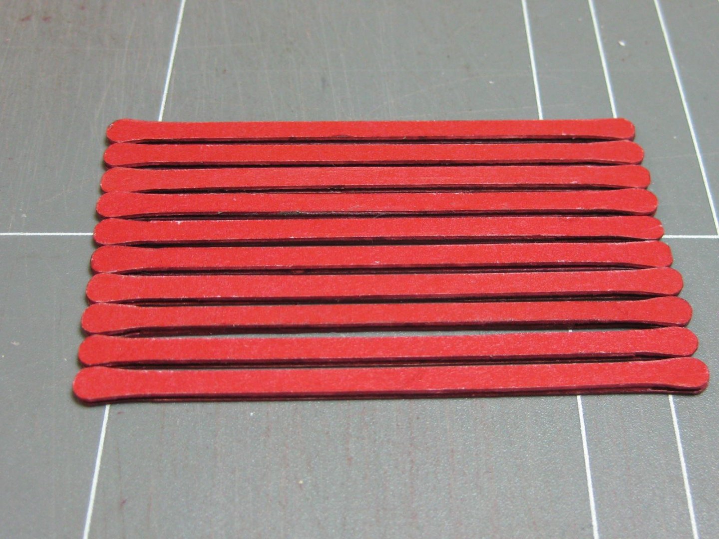
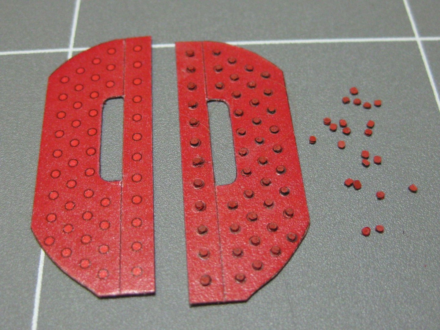
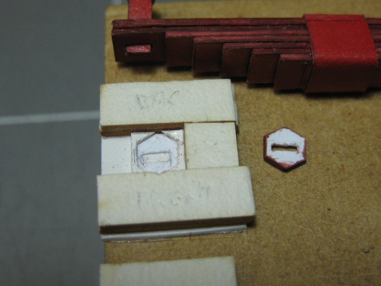
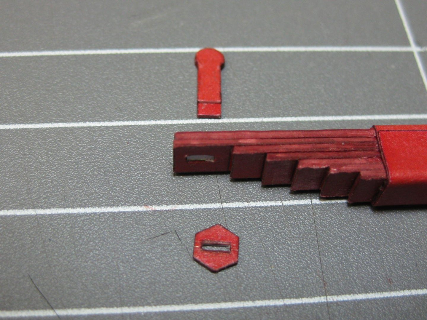
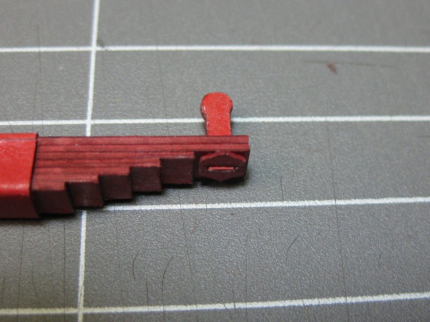
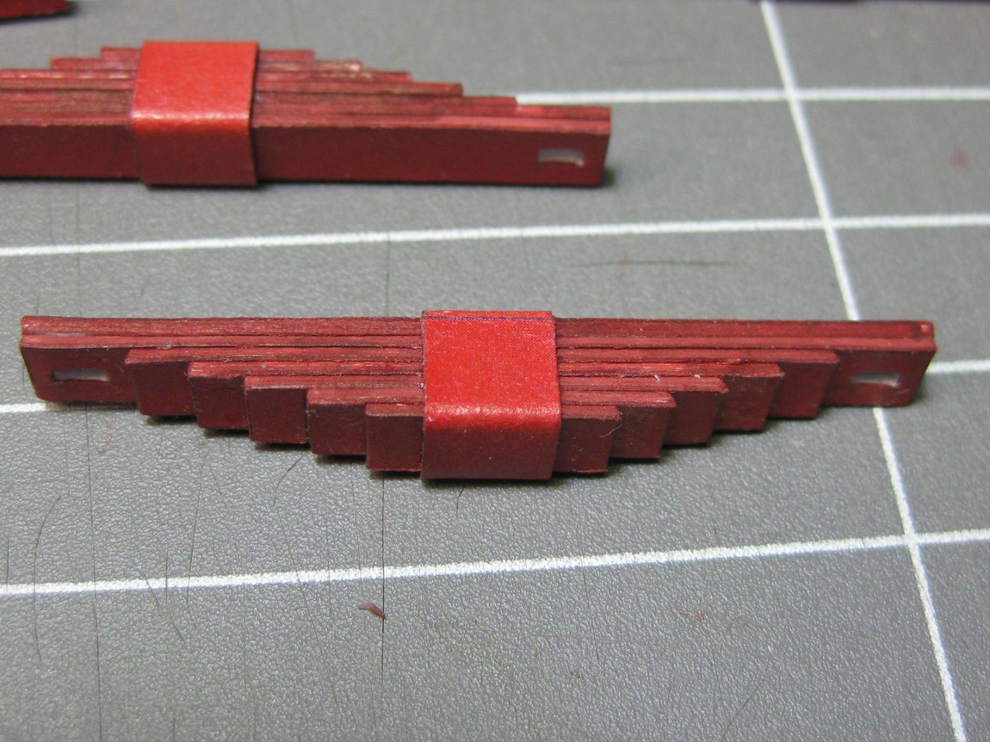
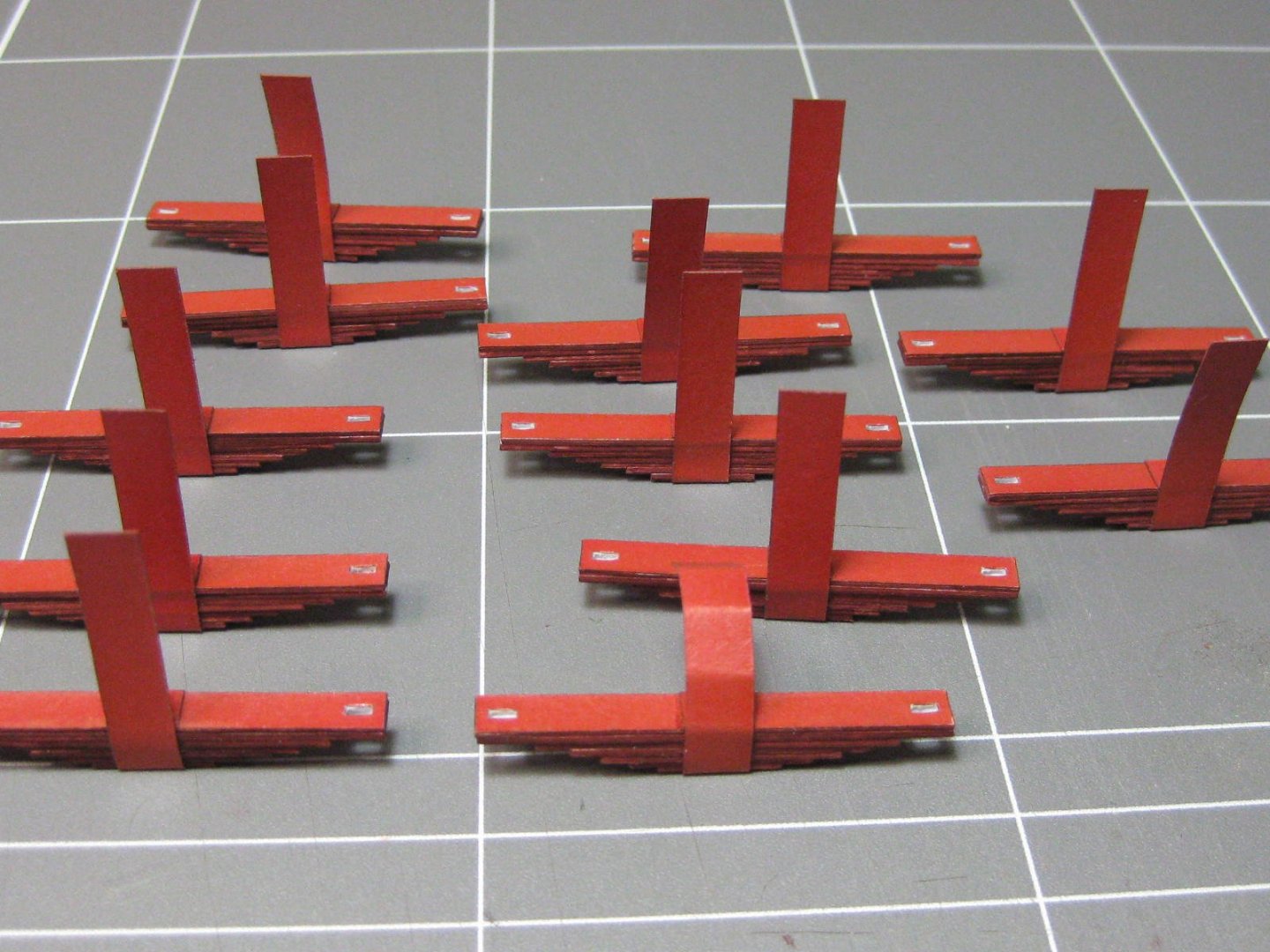
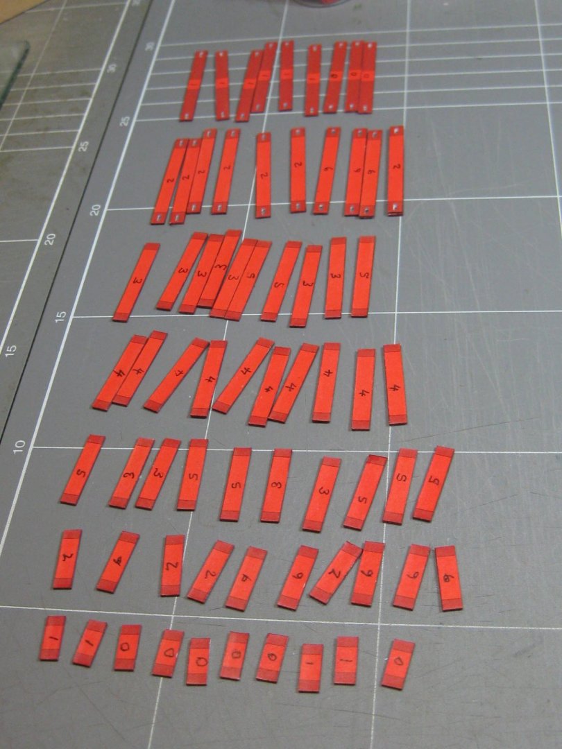
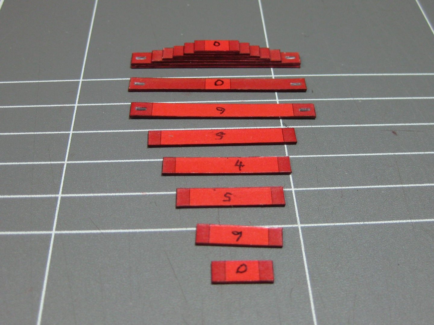
The 12 main springs. These consist of 7 leaves each, all are back-to-back laminated : A doubled binding strap encircles each one : Last things are the support arms and "nuts". I made a jig for ease of assembly of the nuts which saved a lot of time, holding the things was a bit difficult without it : Danny

- 150 replies
-
- 17
-