HOLIDAY DONATION DRIVE - SUPPORT MSW - DO YOUR PART TO KEEP THIS GREAT FORUM GOING! (Only 13 donations so far - C'mon guys!)
×


Dan Vadas
-
Posts
3,261 -
Joined
-
Last visited
Content Type
Profiles
Forums
Gallery
Events
Everything posted by Dan Vadas
-
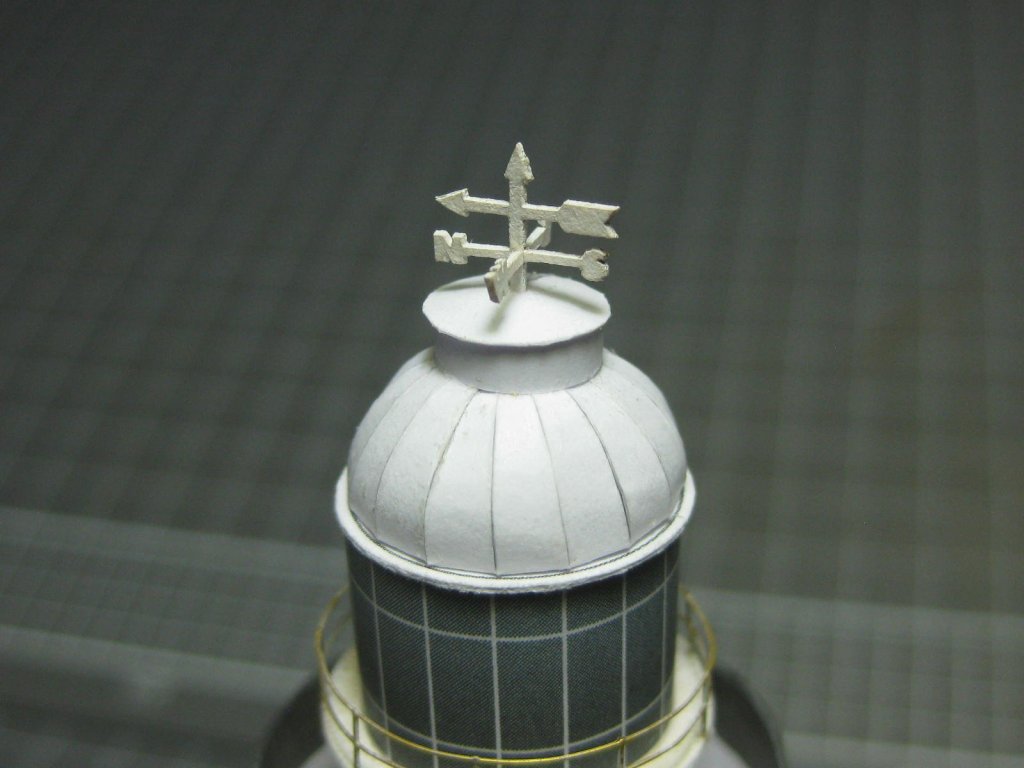
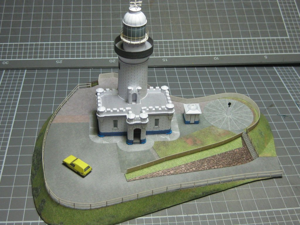
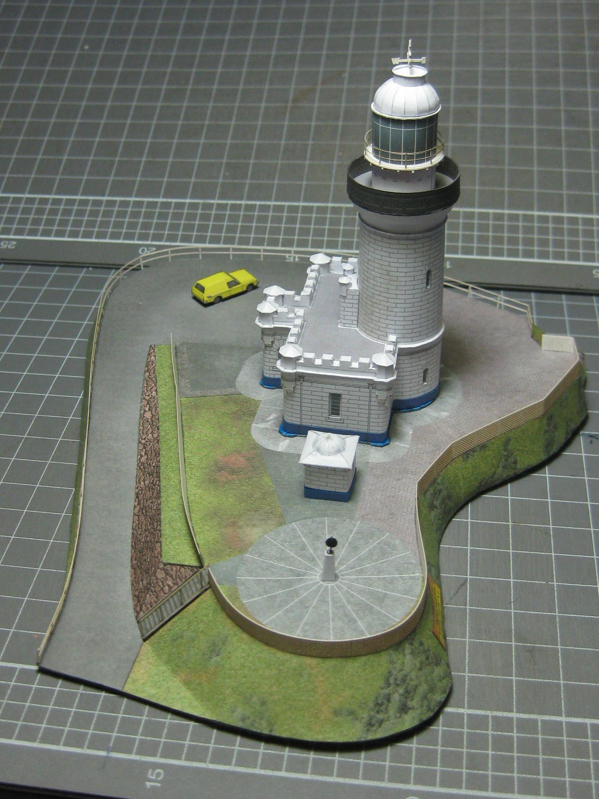
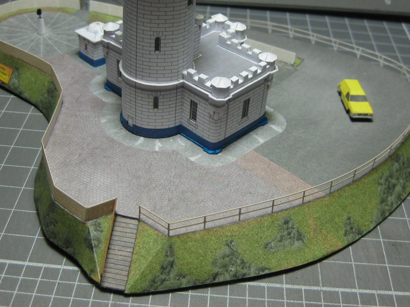
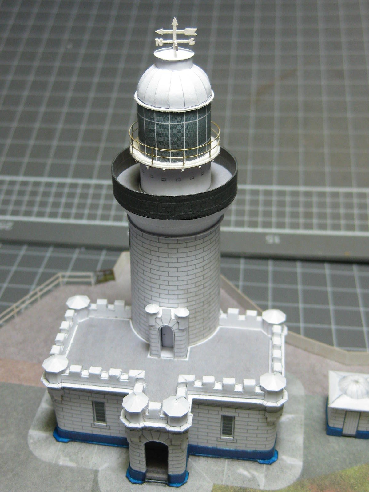
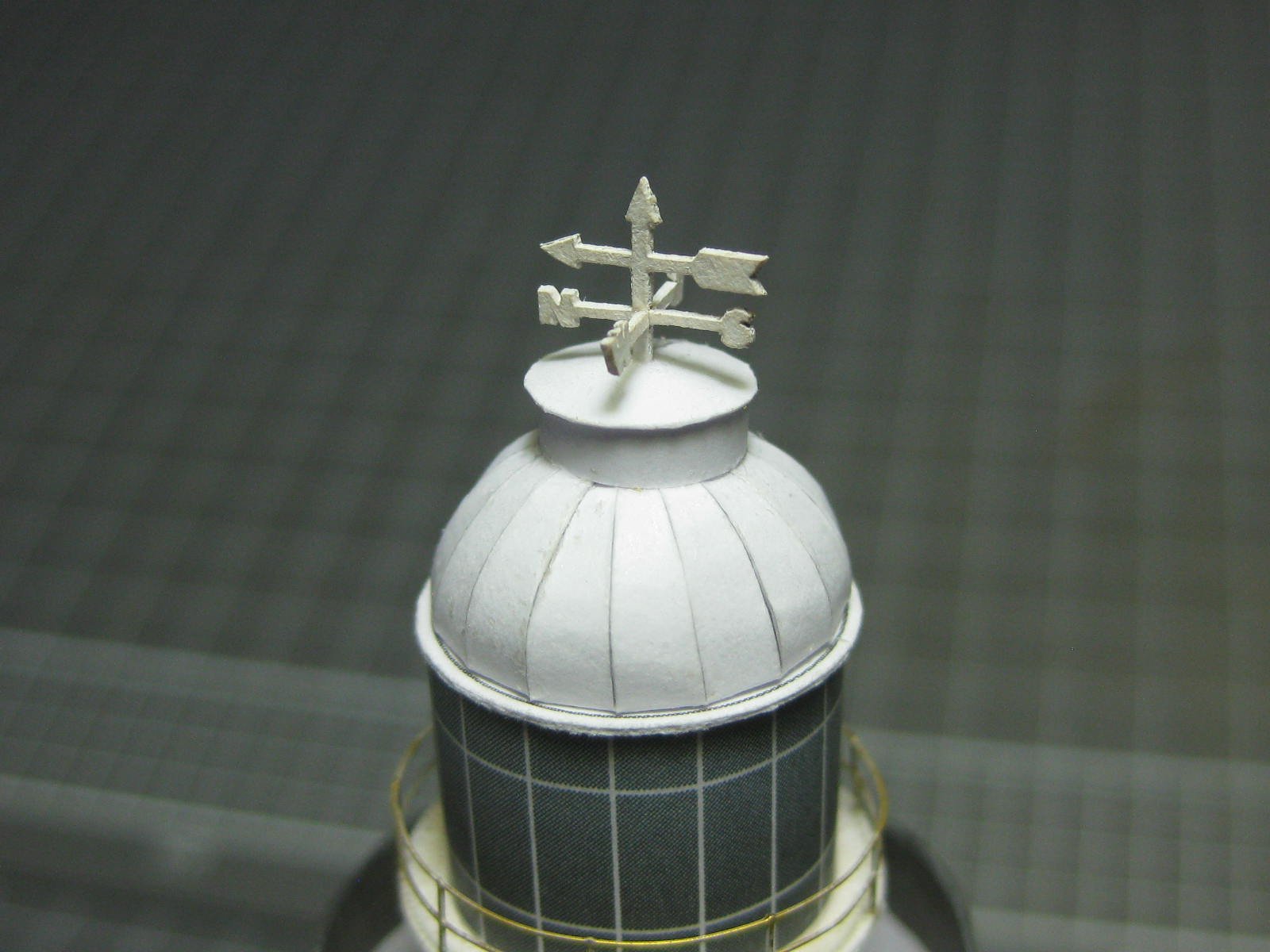
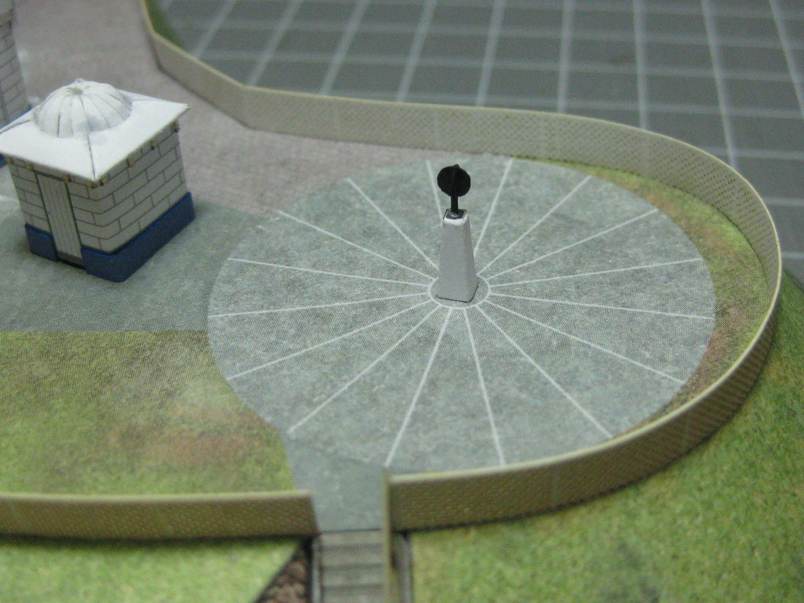
A Weather Vane sits atop the light dome. The orientation of North is correct (before you check it John ) : There is an Anemometer where the original radio antenna used to be. I think the antenna was removed when radio technology improved : With the fitting of the safety railings the model is FINISHED : Danny


- 16 replies
-
- 21
-

-
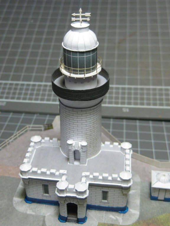
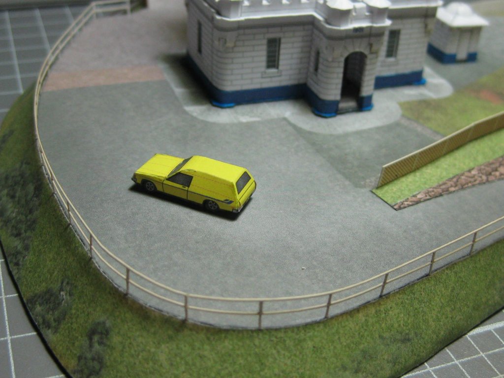
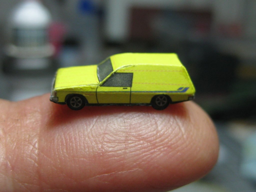
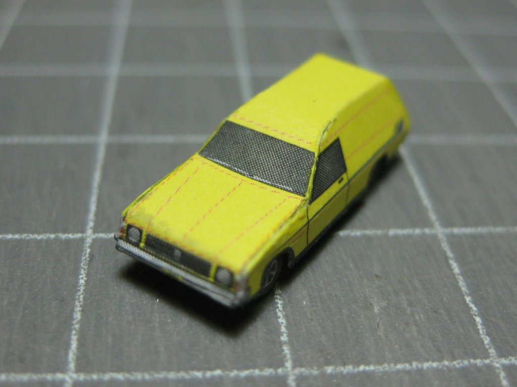
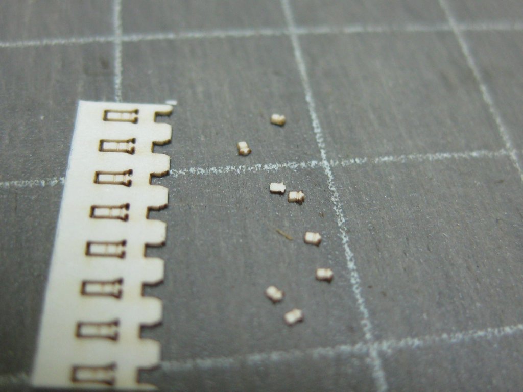
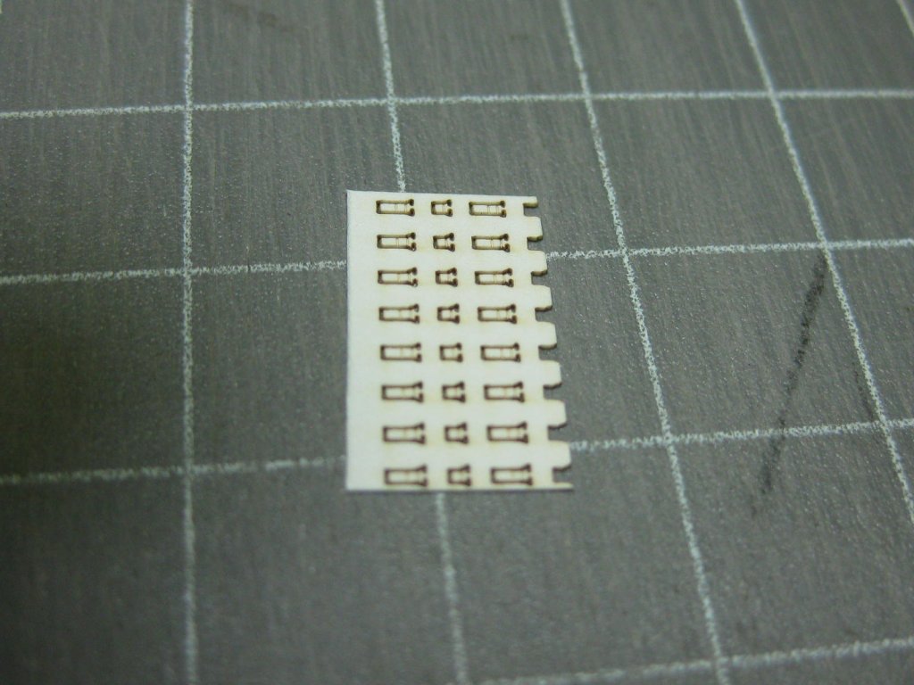
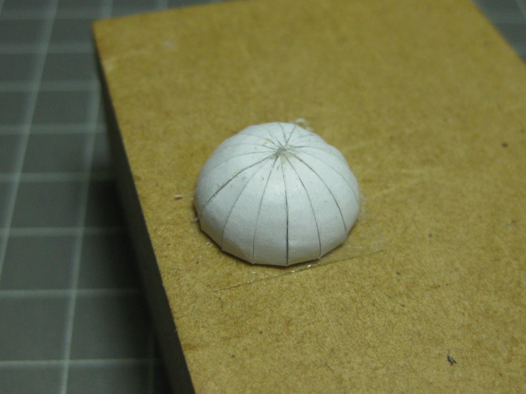
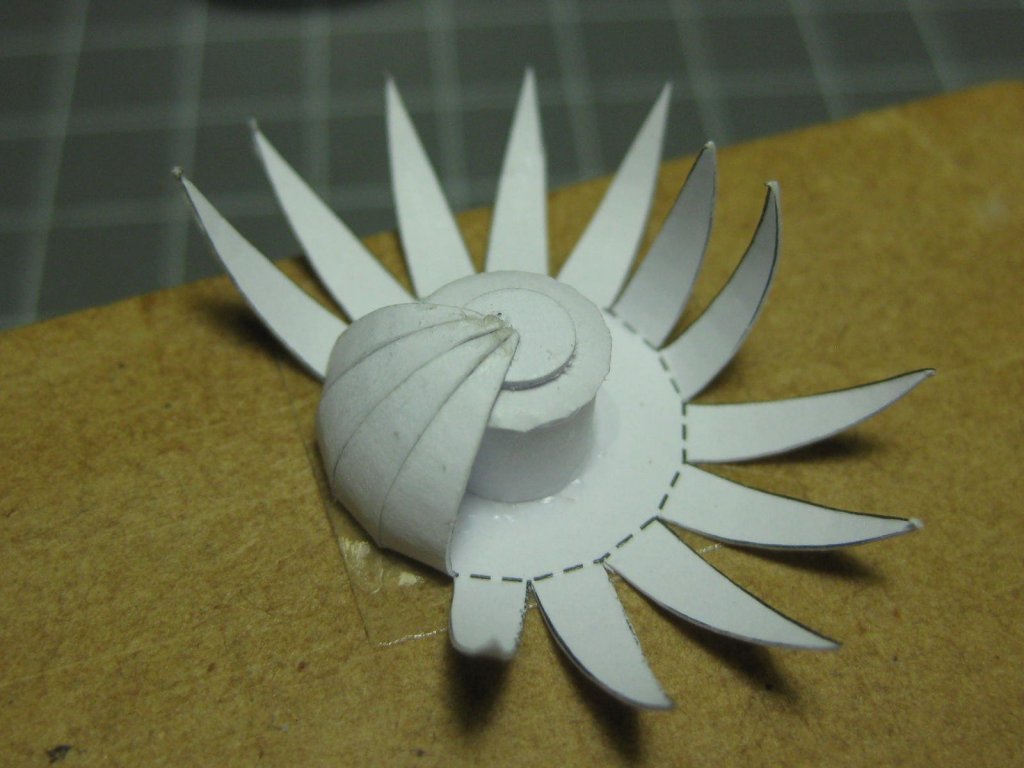
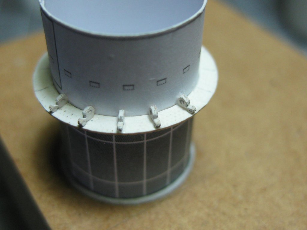
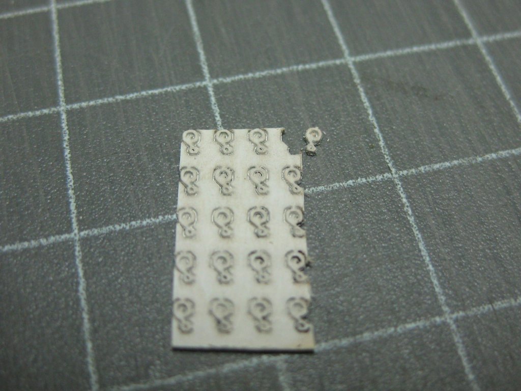
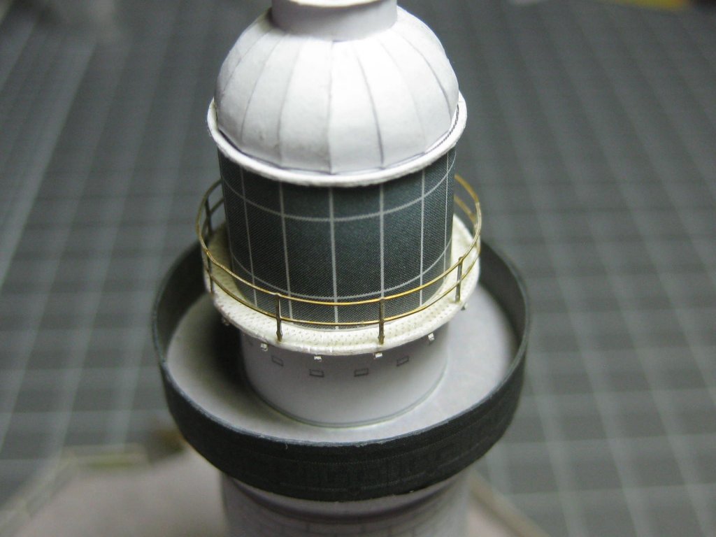
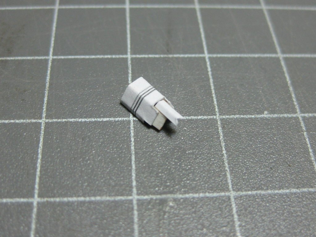
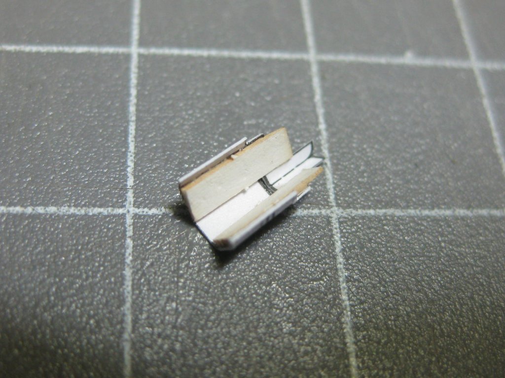
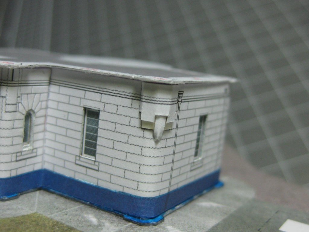
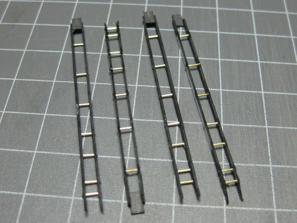
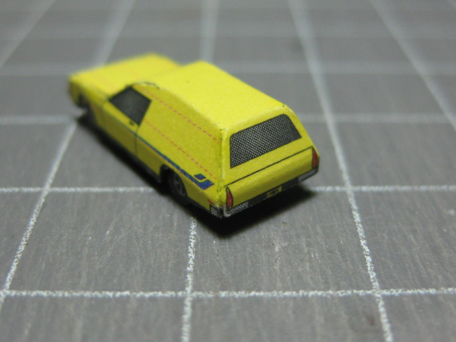
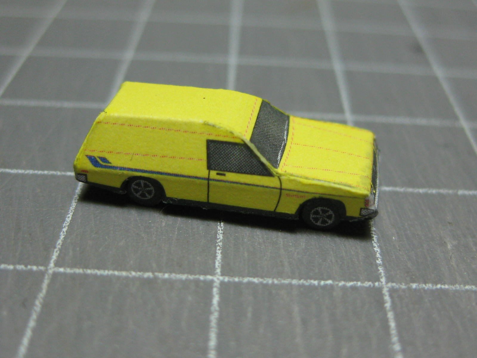
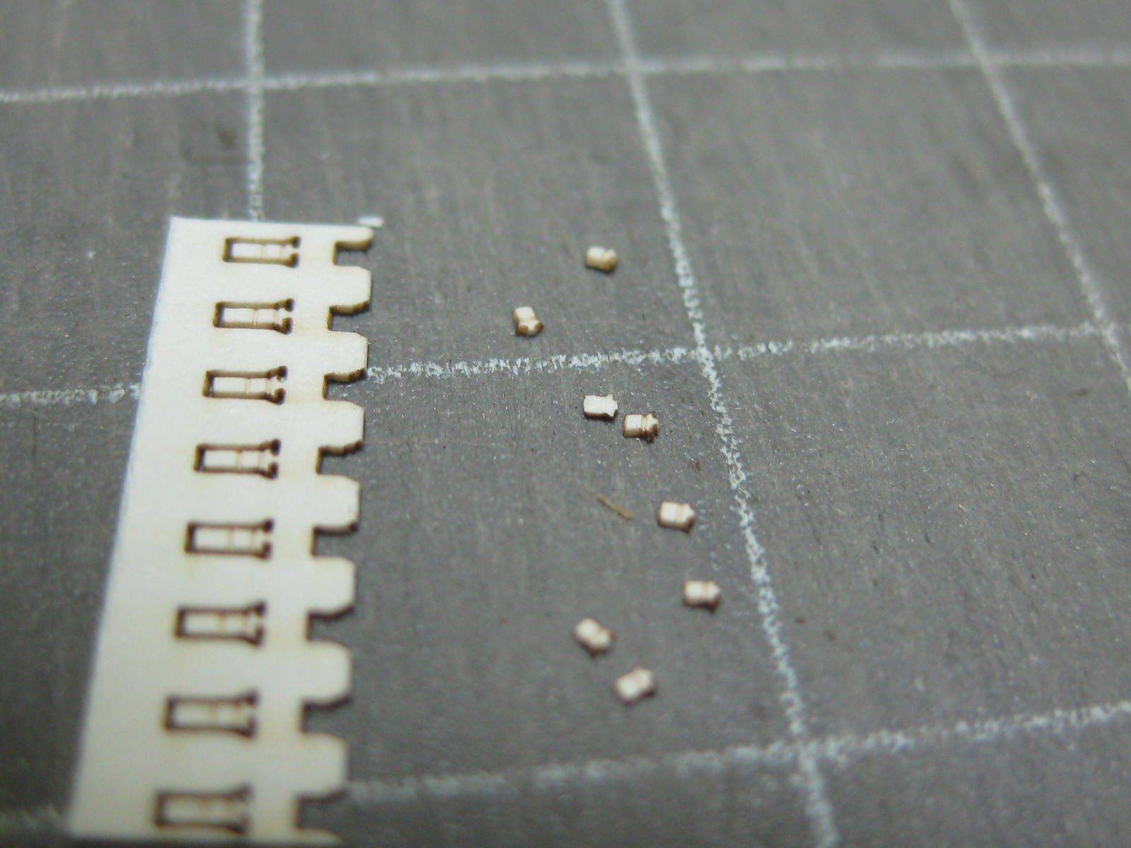
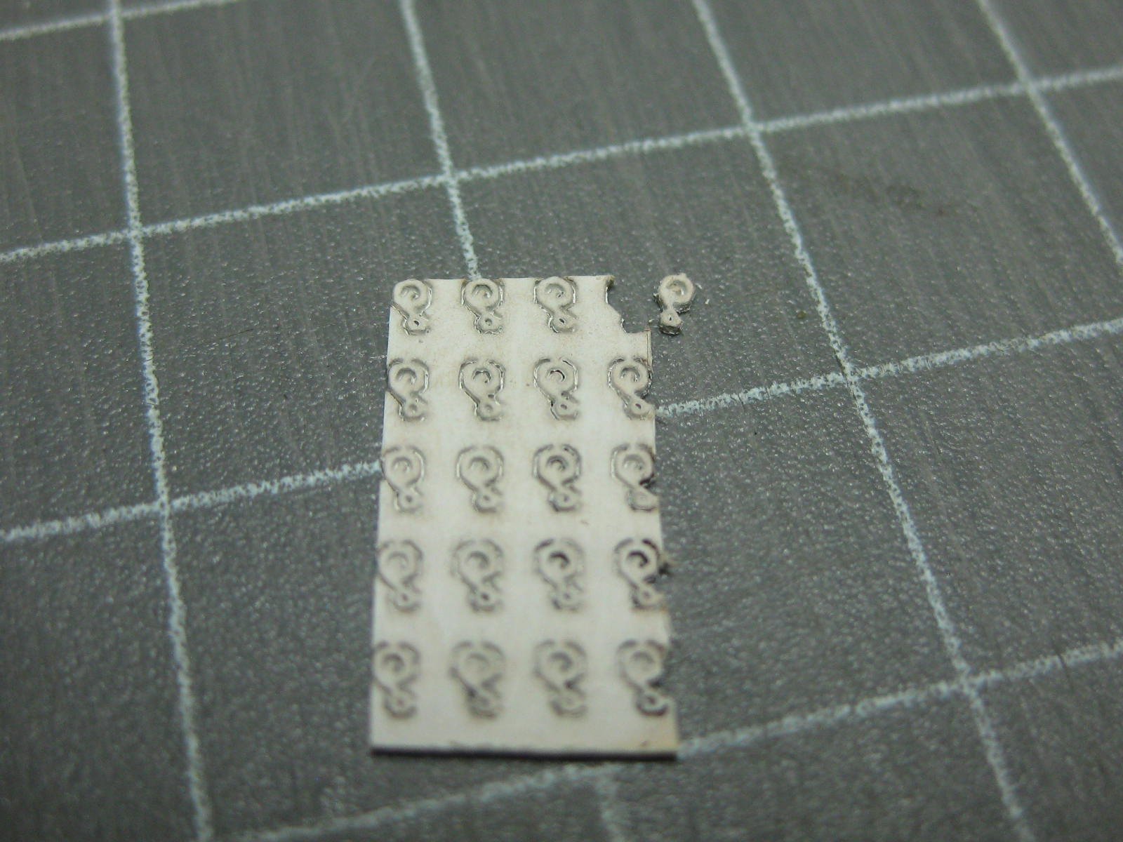
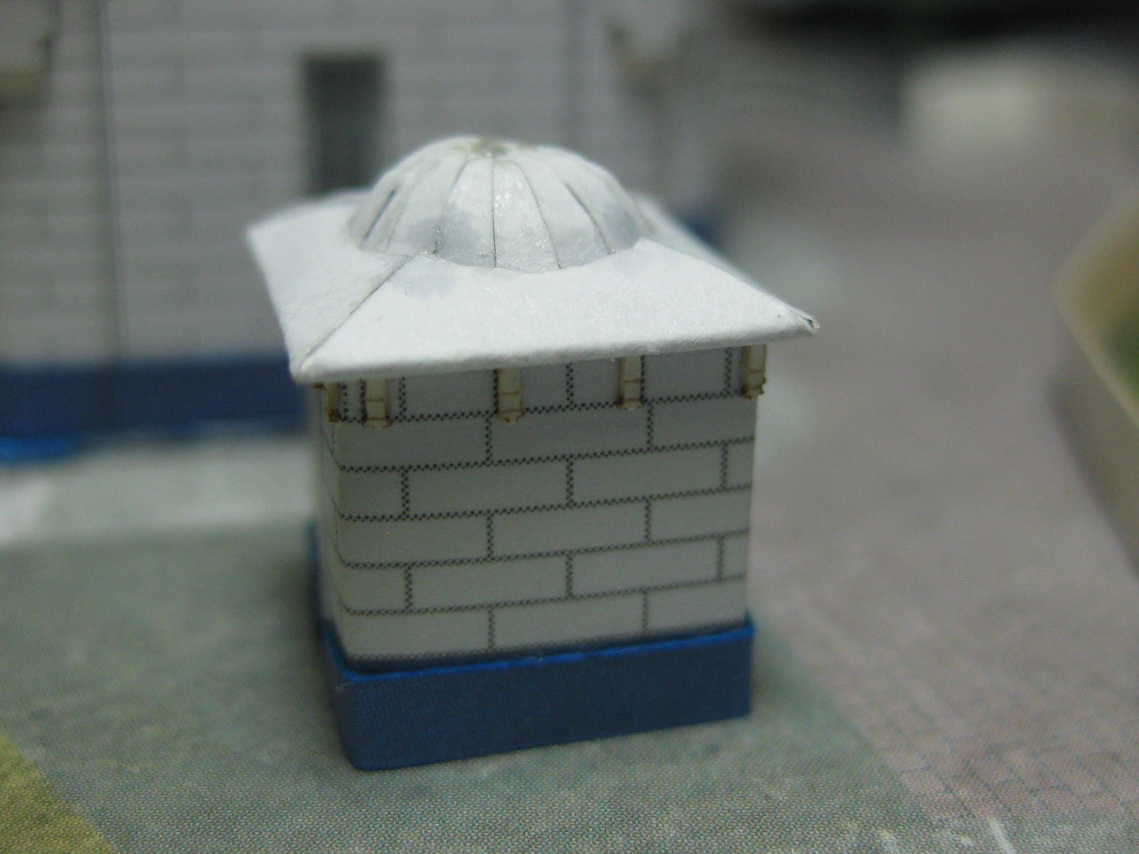
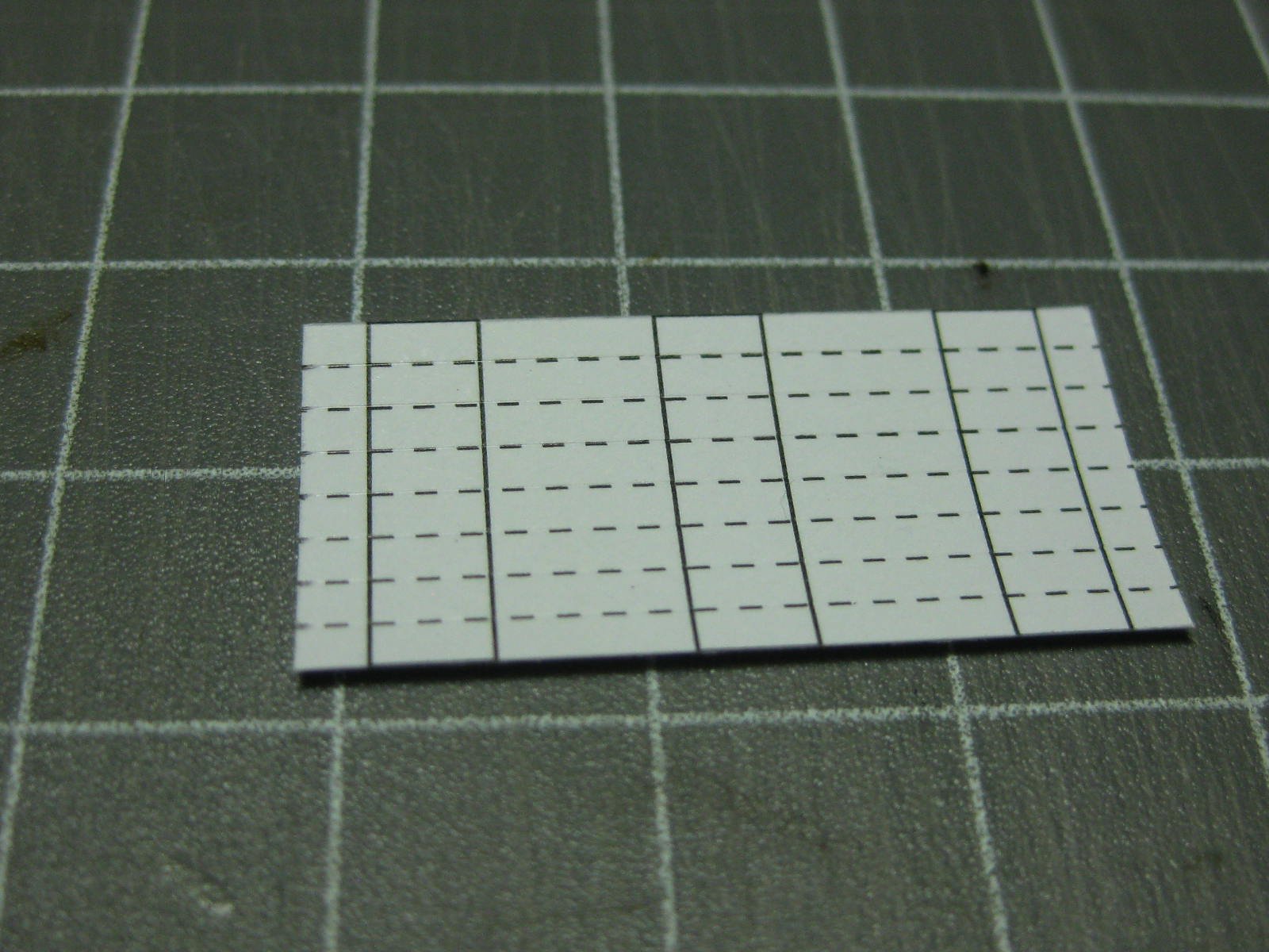
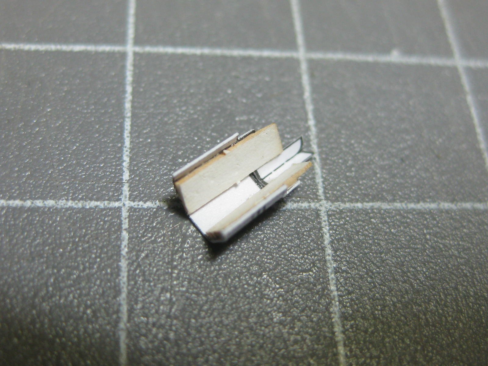
Thanks guys . Here's the light. There are laser-cut parts to be fitted, starting with these "wrought iron" brackets which support the mesh railing under the light : The dome on top of the light came out well, thanks mainly to the support I fitted in the middle of it : I used a piece of PE brass railing left over from one of my ships to make the platform rail. It's not quite the right spacing between posts, but who would know ? These are officially the smallest paper pieces I've ever fitted, they represent brick supports : The bricks fit under the roof of the toilet : A little bonus - a WB Holden Sandman Panel Van which took me about 3 hours to make. The kit supplies two of these plus two Kombi Vans which are optional extras. One was enough : Danny


- 16 replies
-
- 14
-
-
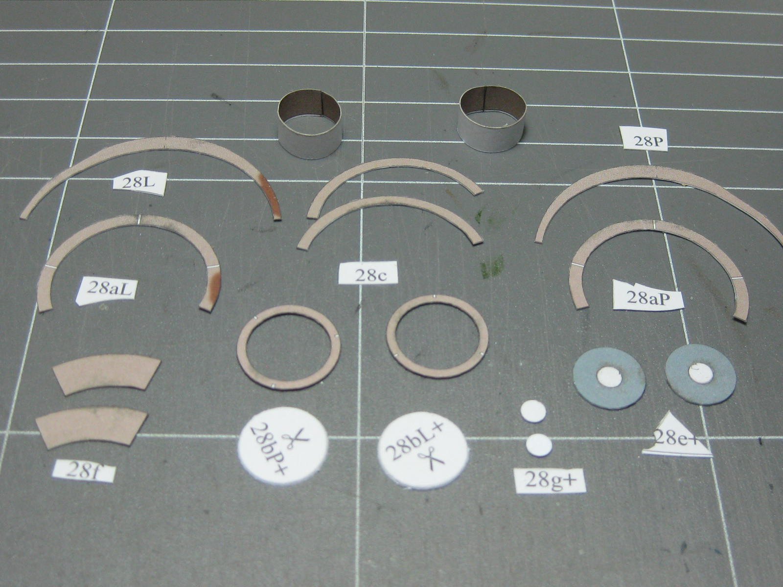
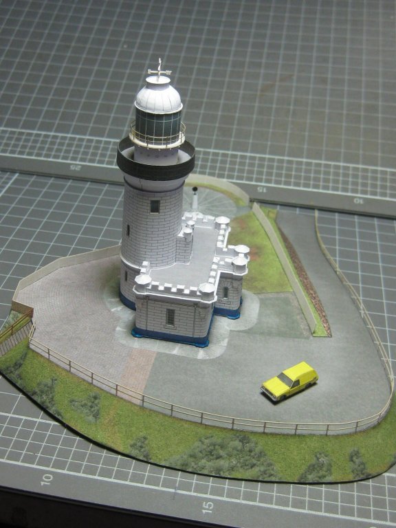
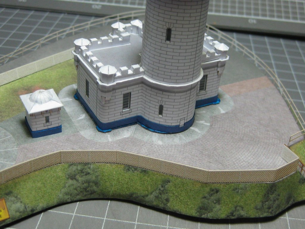
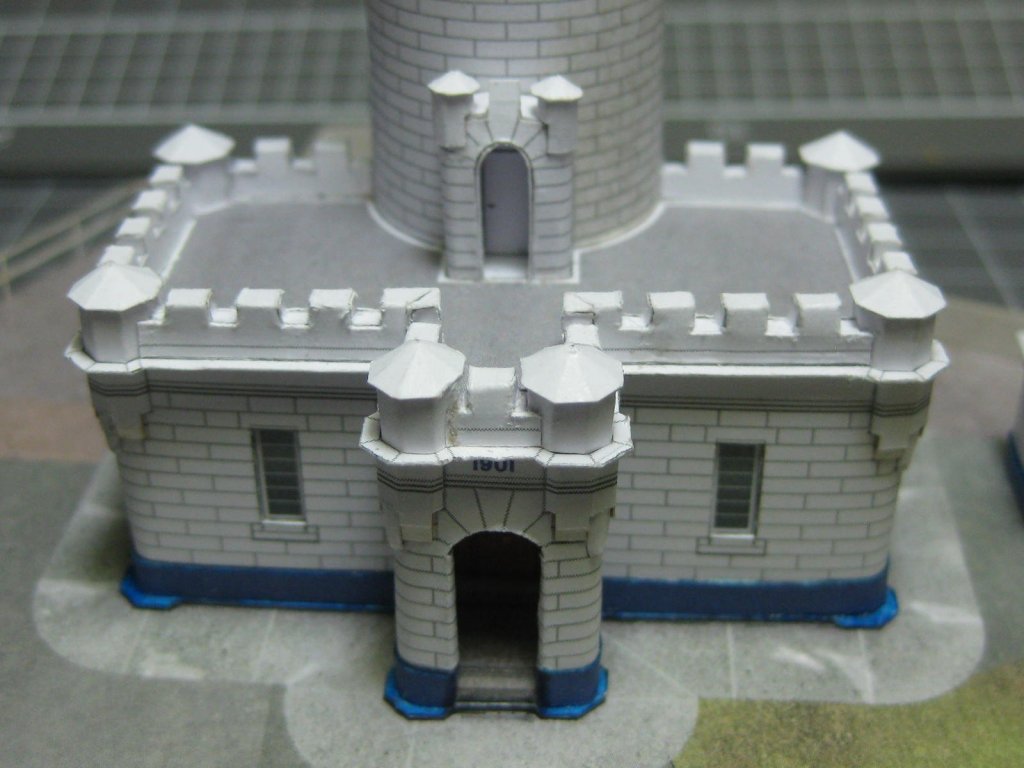
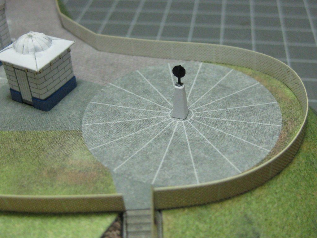
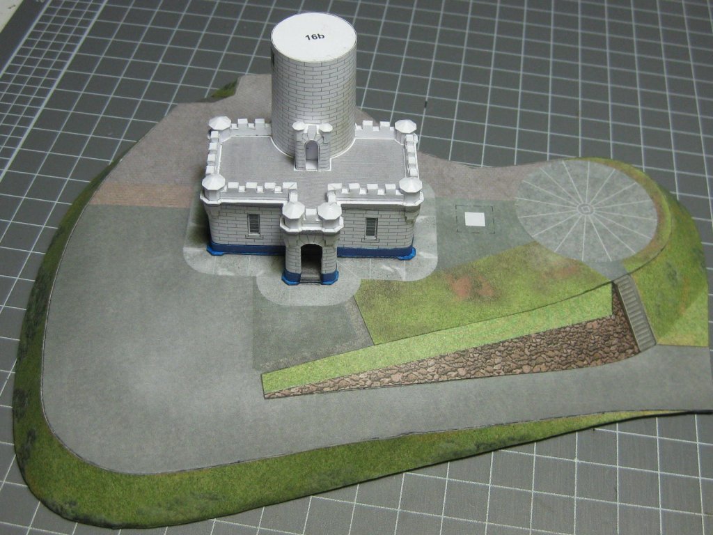
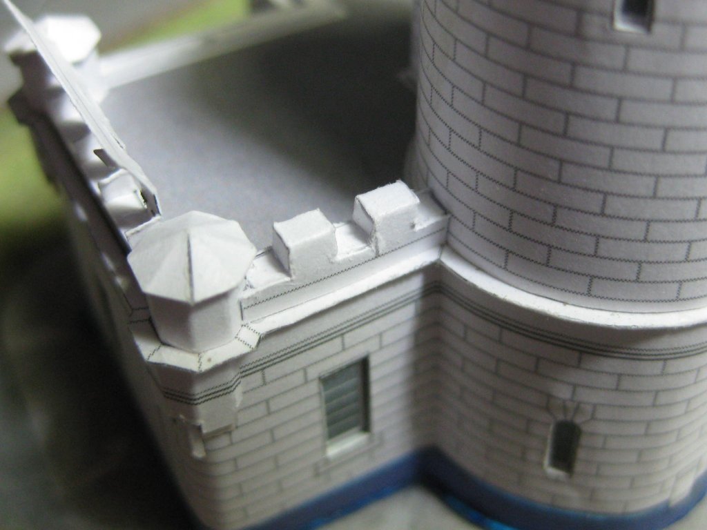
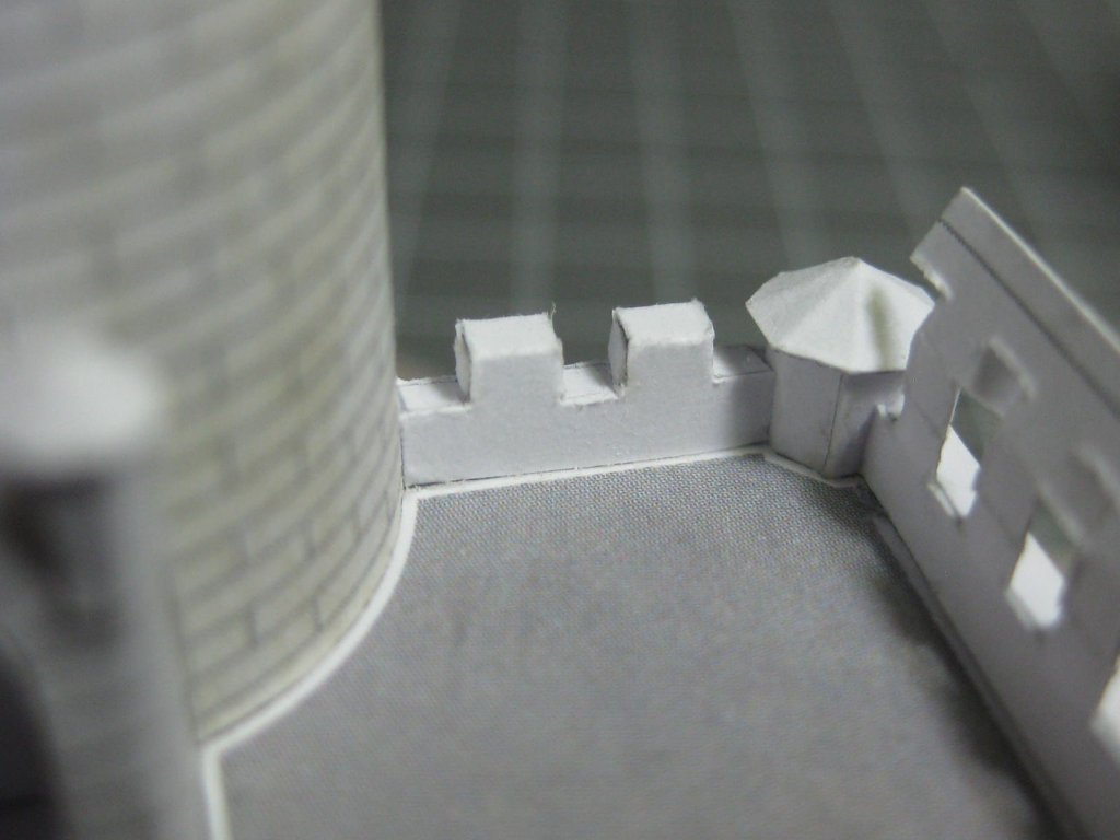
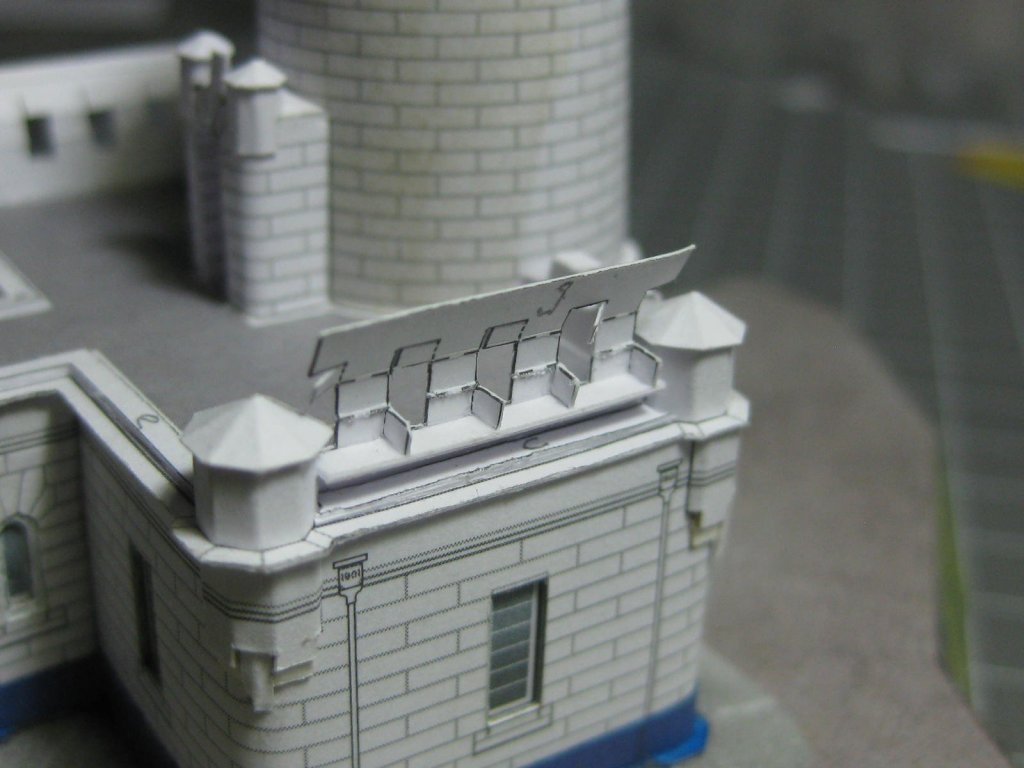
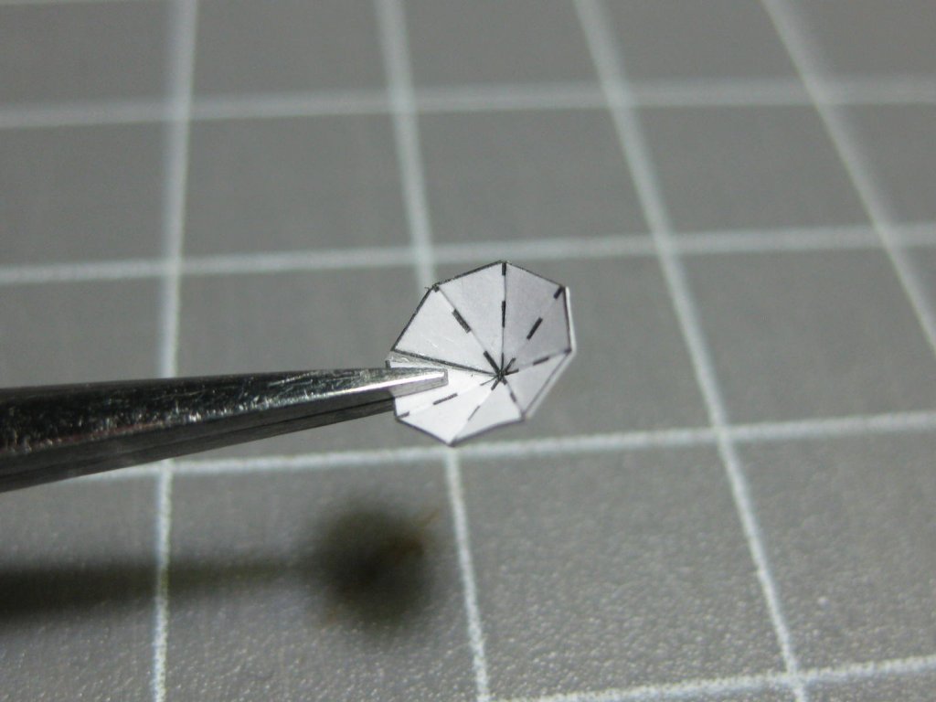
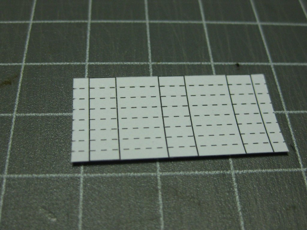
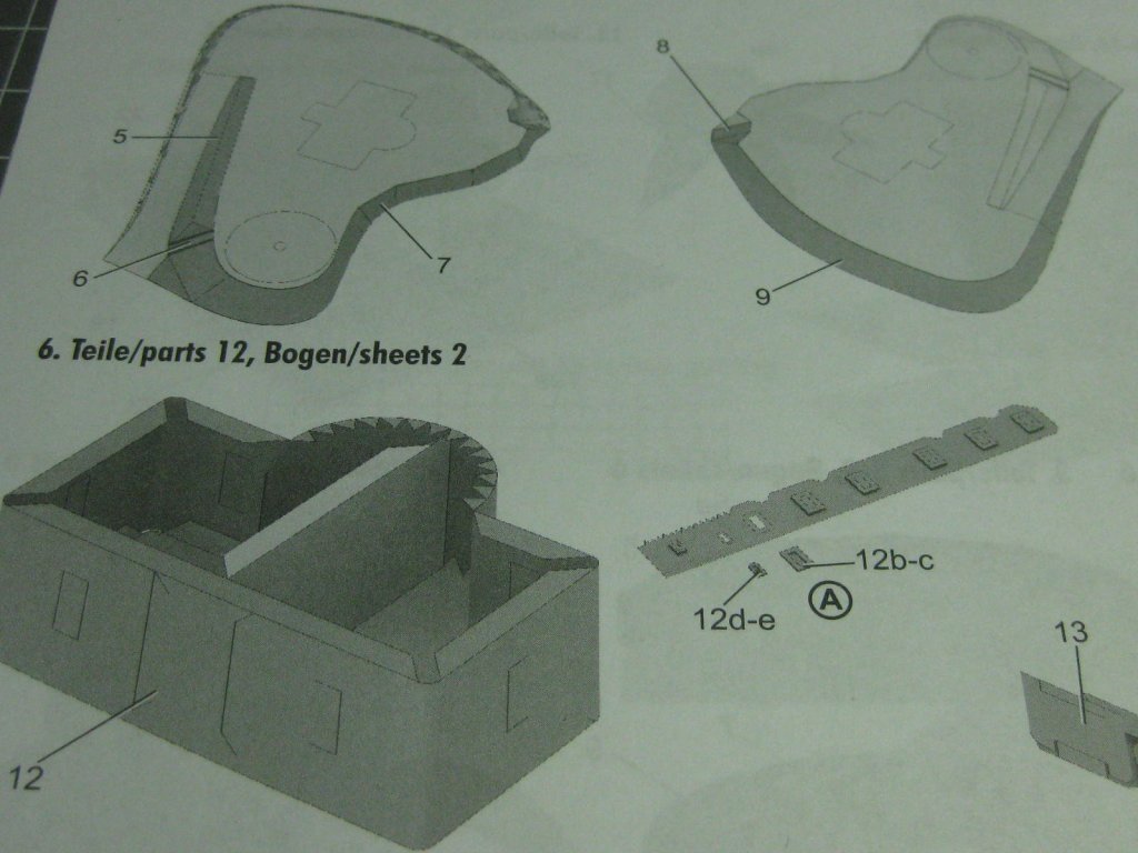
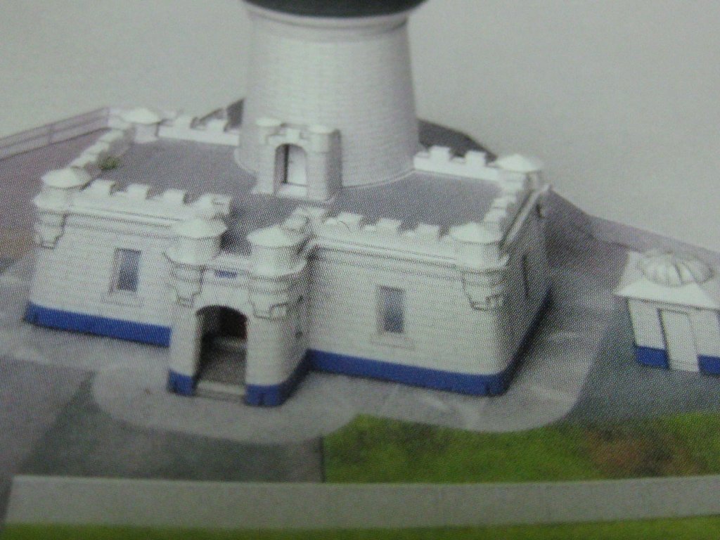
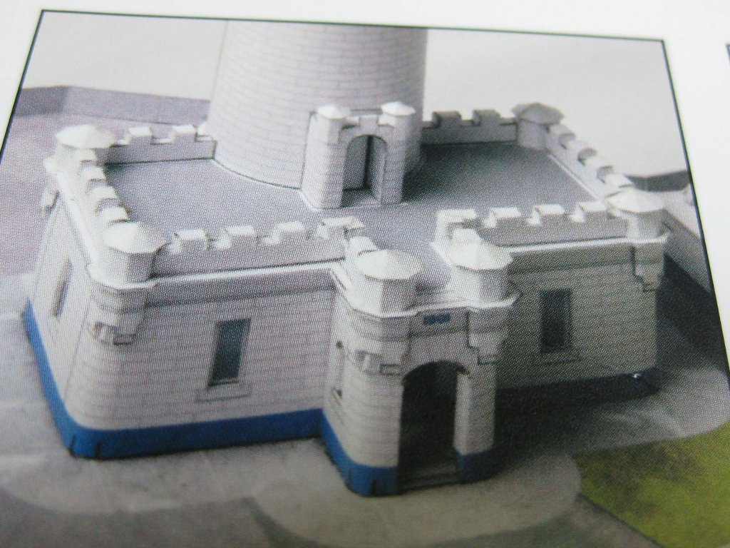
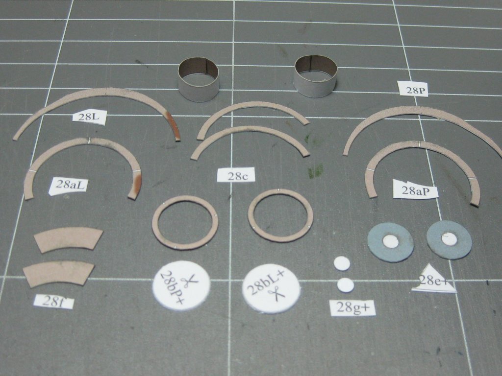
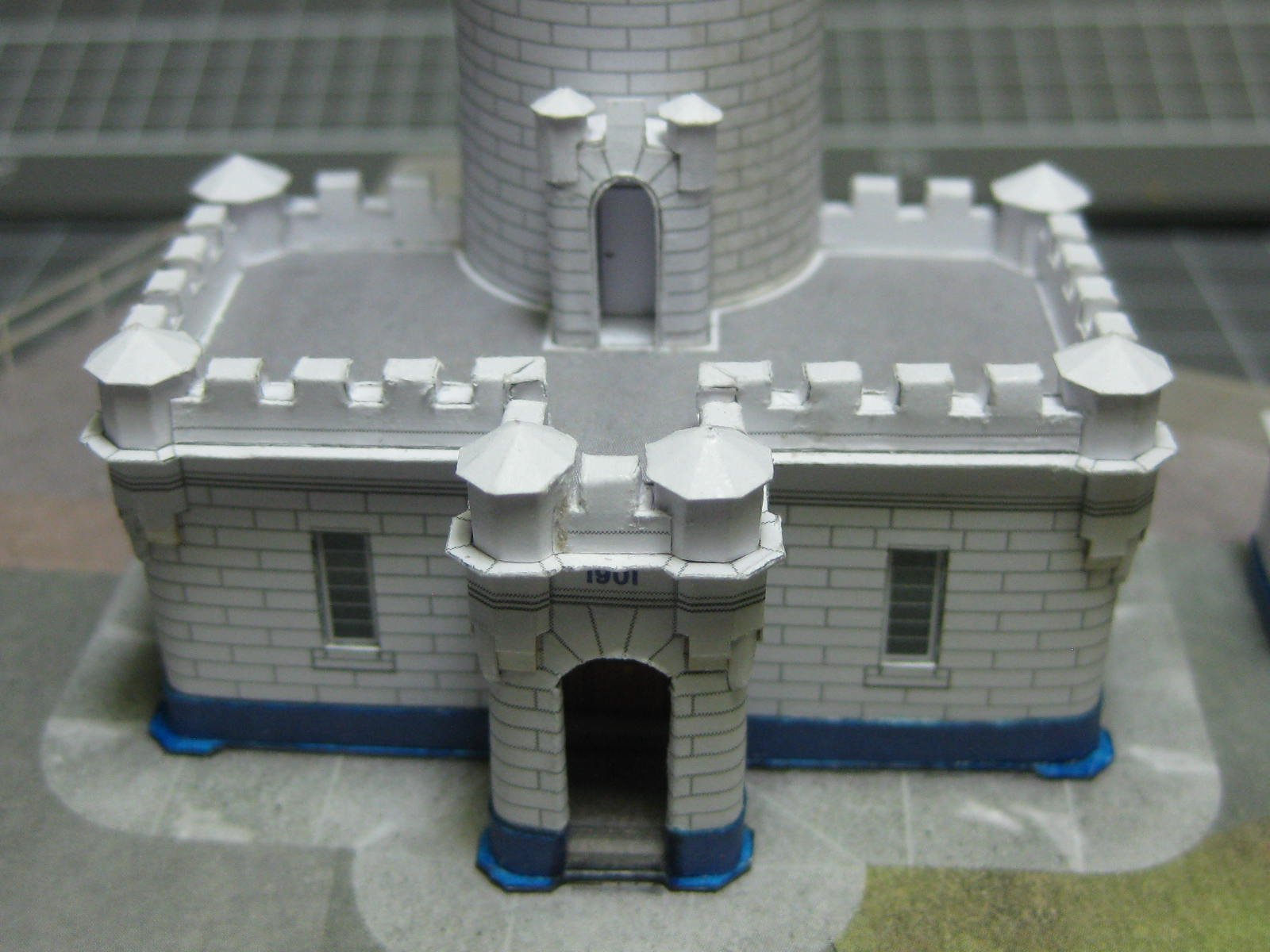
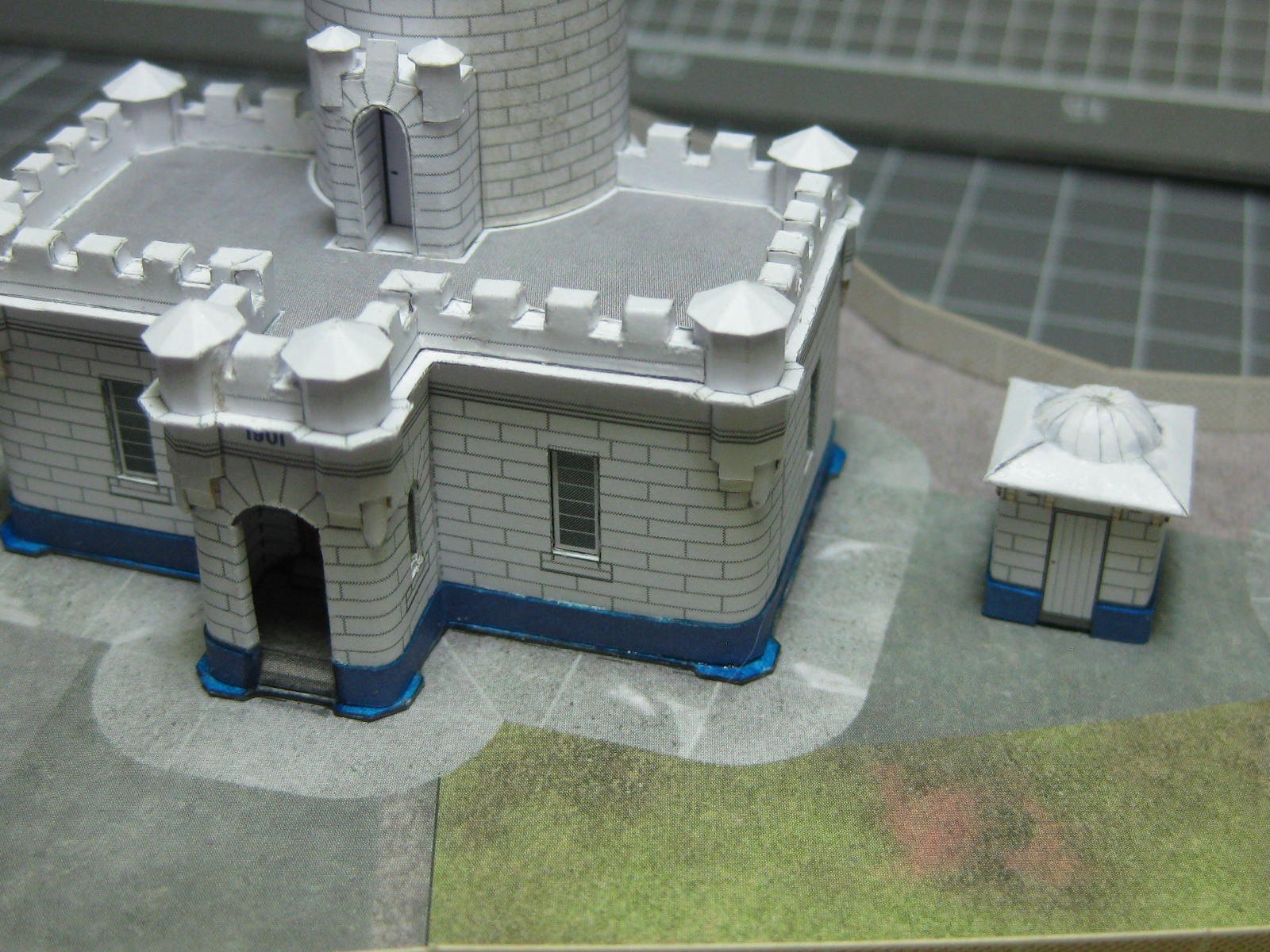
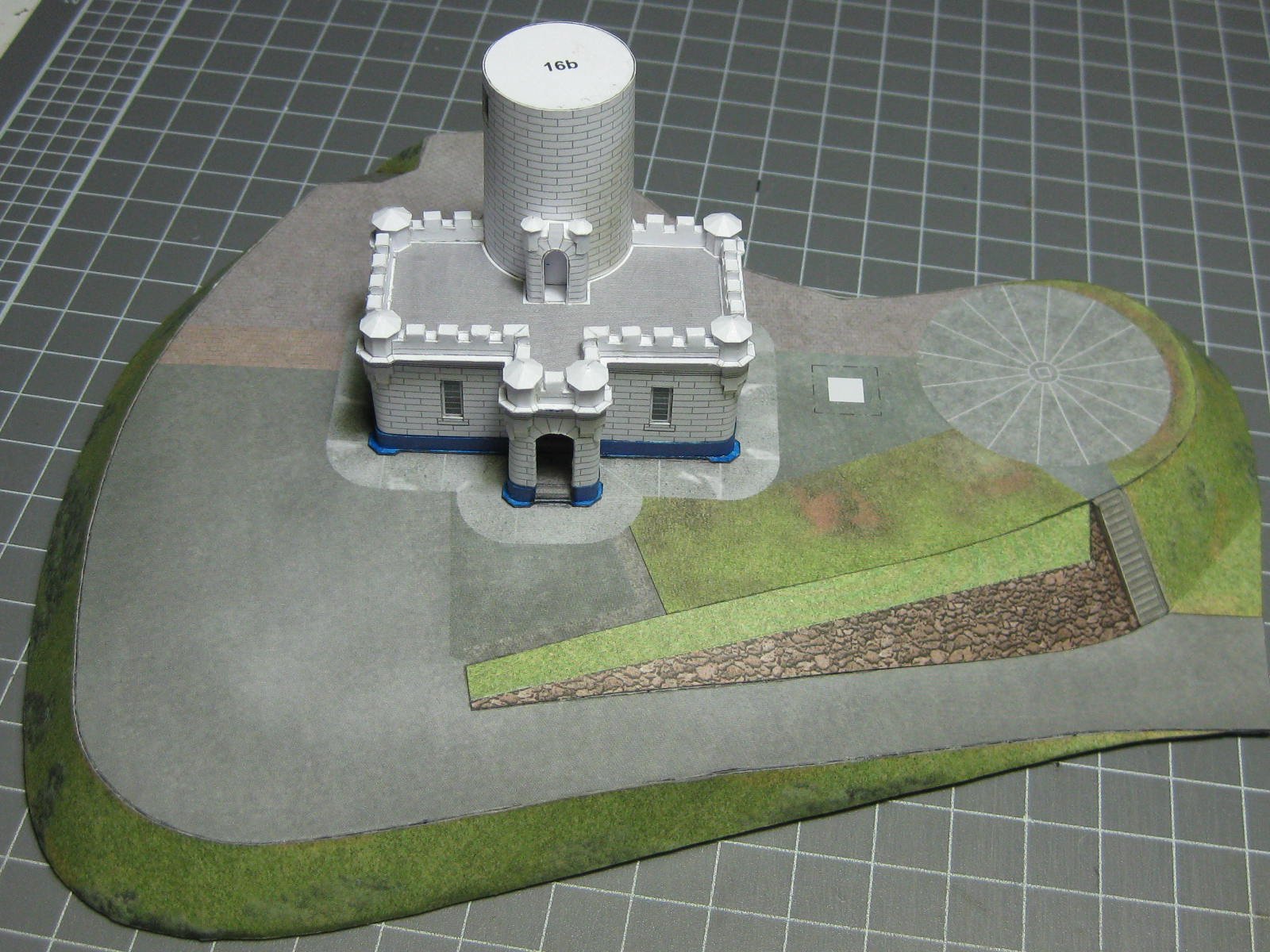
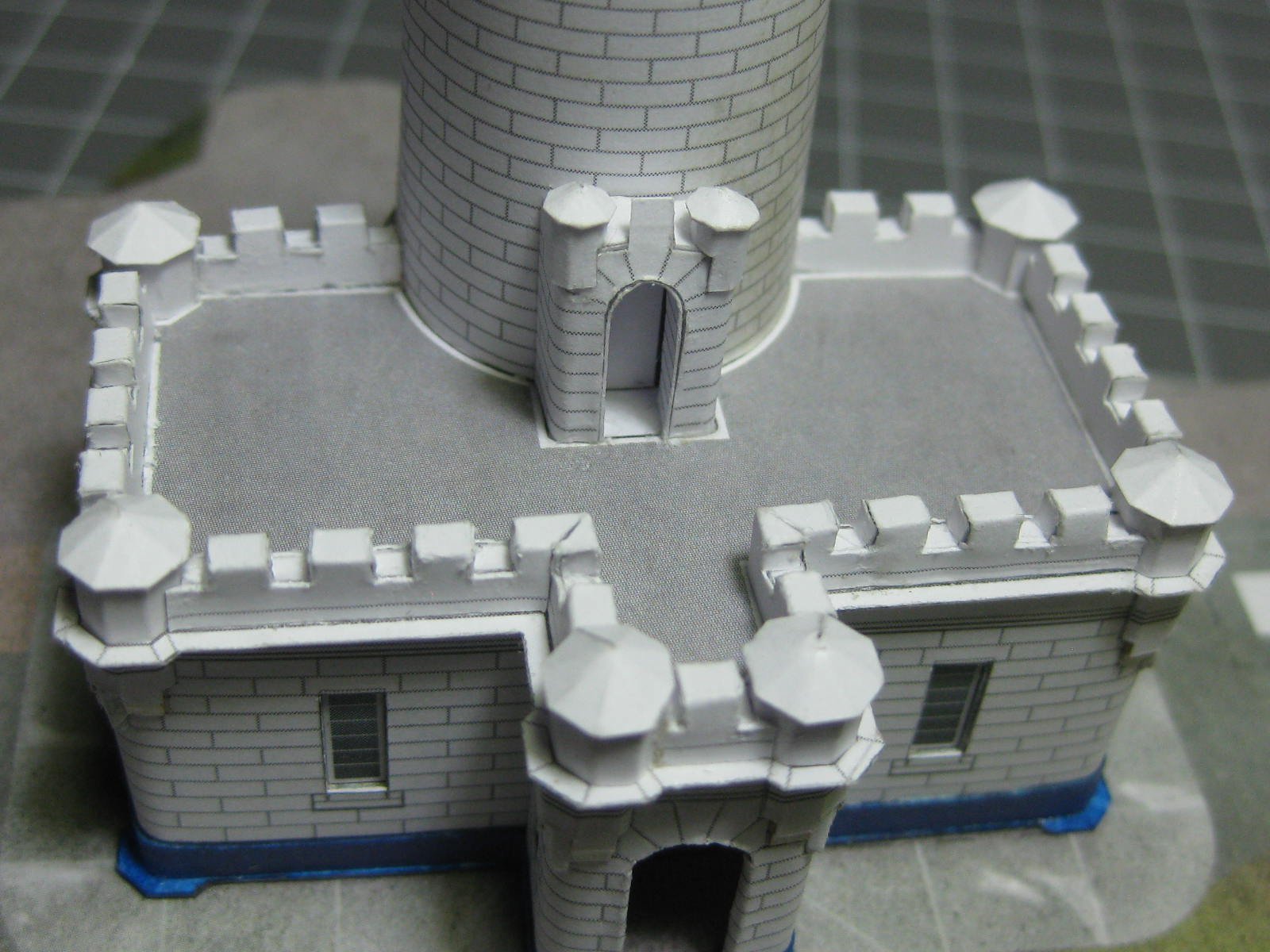
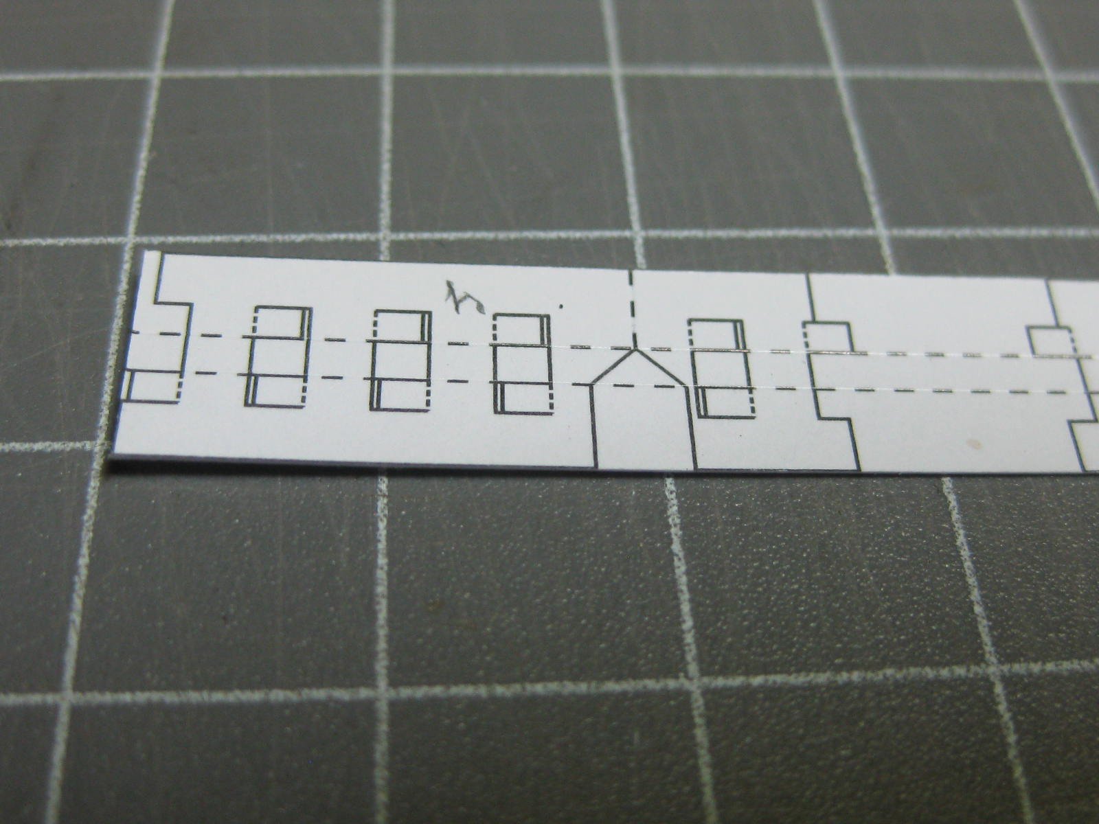
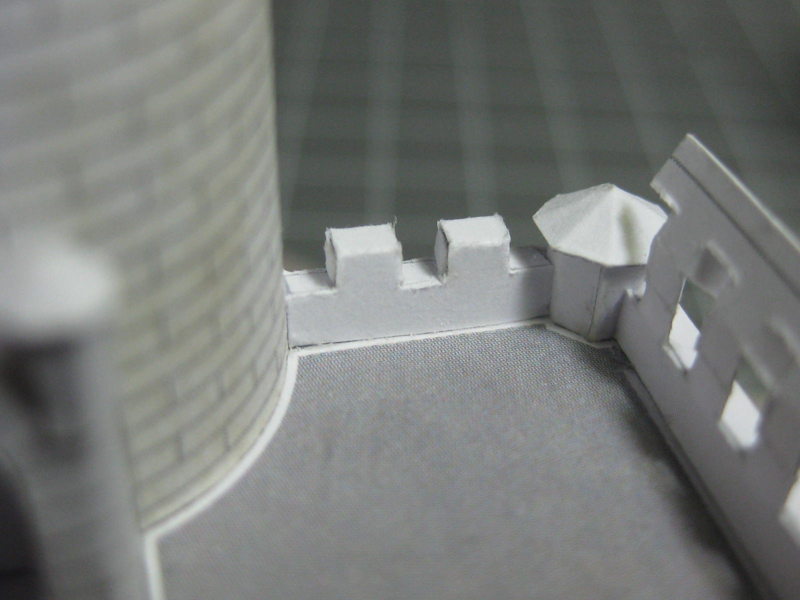
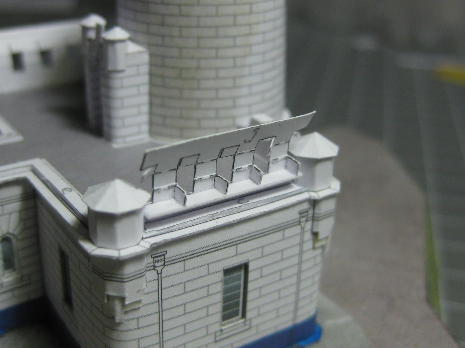
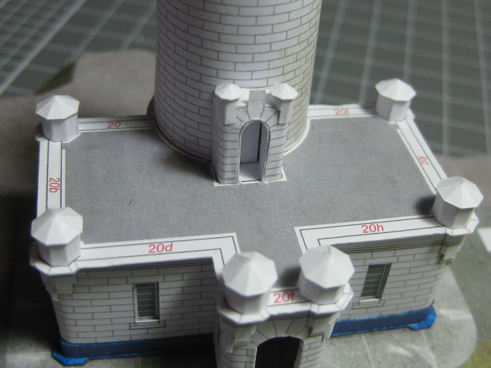
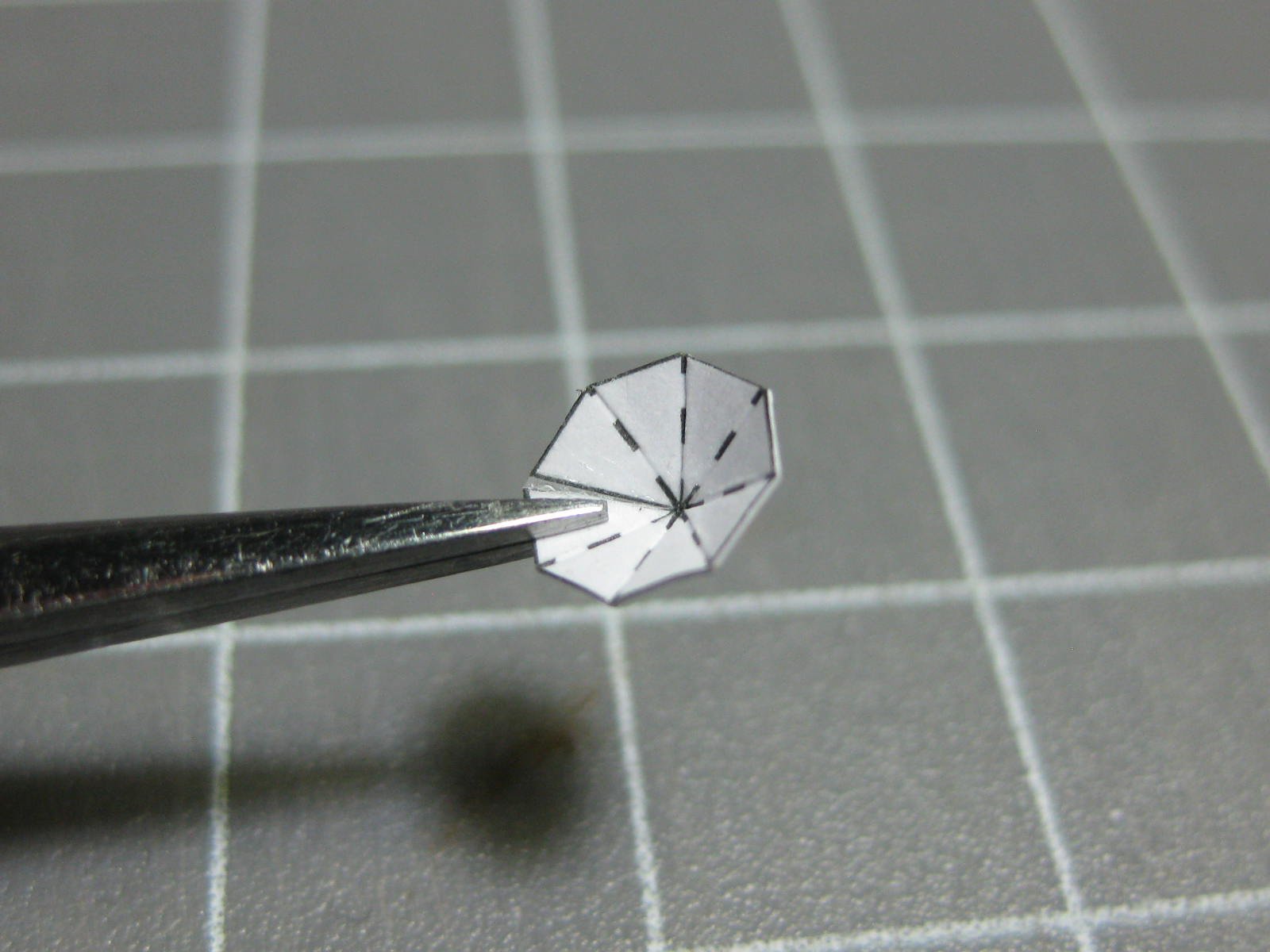
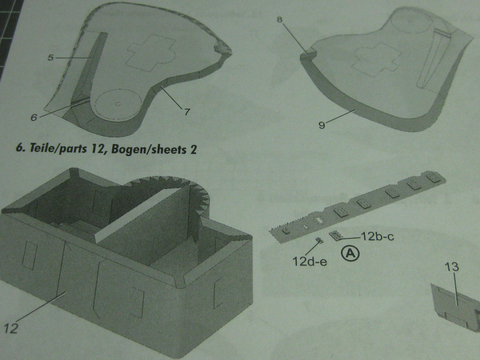
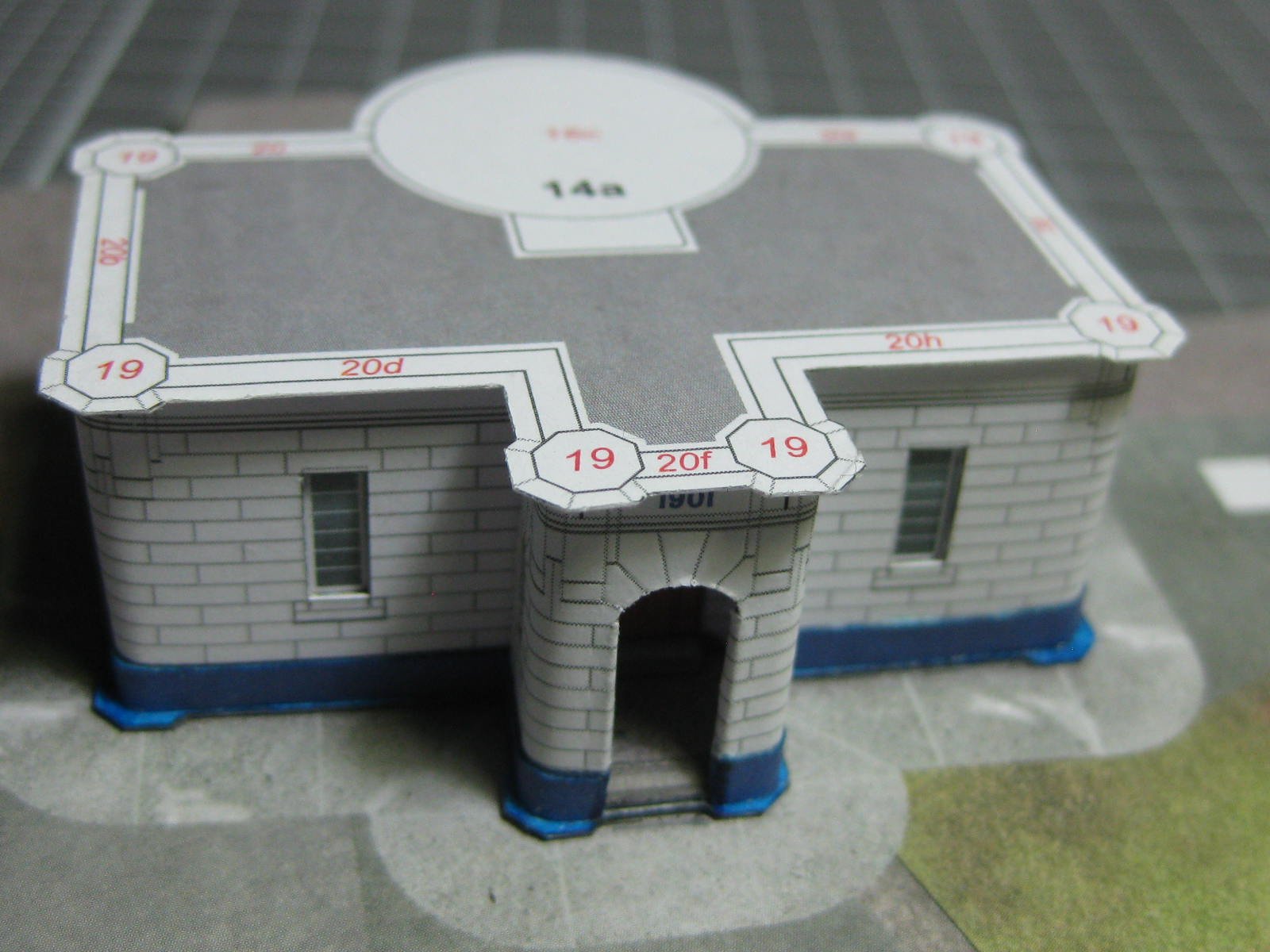
A "cupola" is fitted to each corner of the deck. This is the card of parts for them. I scored all the fold lines before cutting out the individual pieces. One good (but at first confusing) feature of this kit is that all fold lines are printed on the BACK side of the part, so they don't show on the finished side. Cut lines on folded parts are also printed on the back side : One of the cupola roofs : The cupolas fitted : Next is the very complex "castle" type battlements. The instructions don't give much of an idea on how they are assembled, but I managed to work it out OK. Once again these are printed on the back side of the part, the face side is just blank white. Careful cutting was needed : The battlements fitted. I glued these in stages and let the glue set between each stage. I also added extra support pieces to the deck and under each lower section. It would have been very difficult to assemble each piece without them. These were actually quite a bit easier to do than they appear : An overview of the lighthouse to date. The light itself is the next stage : Danny


- 16 replies
-
- 15
-
-
Quite correct John . Danny
-
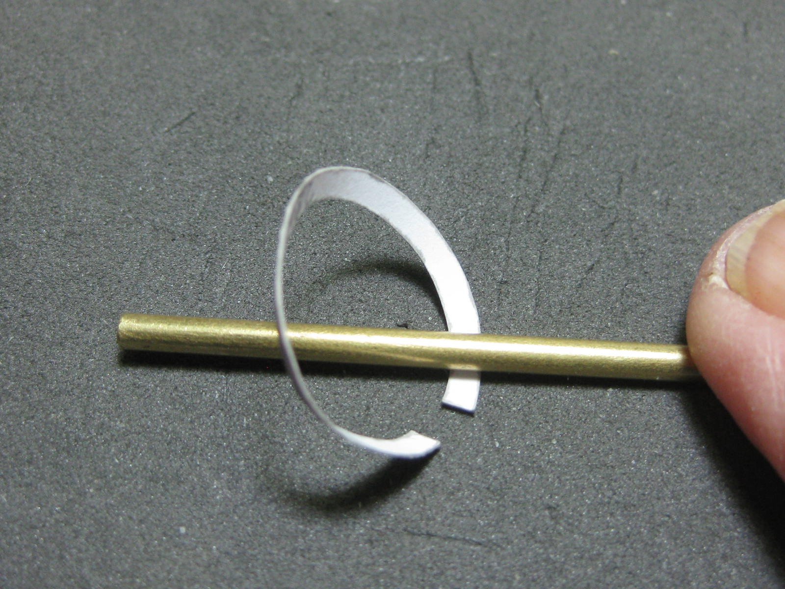
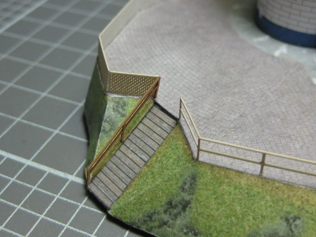
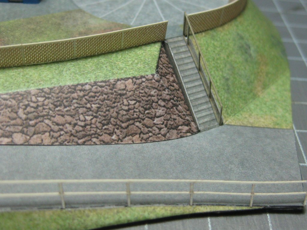
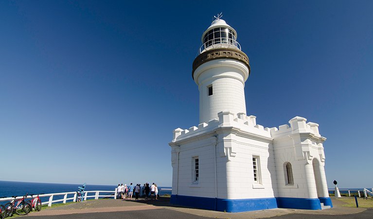
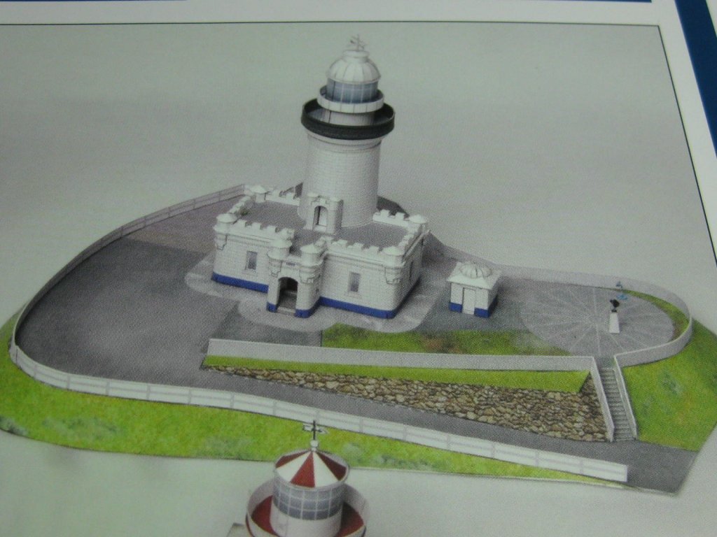
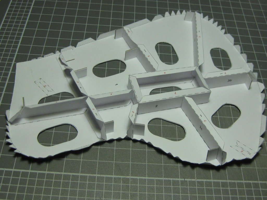
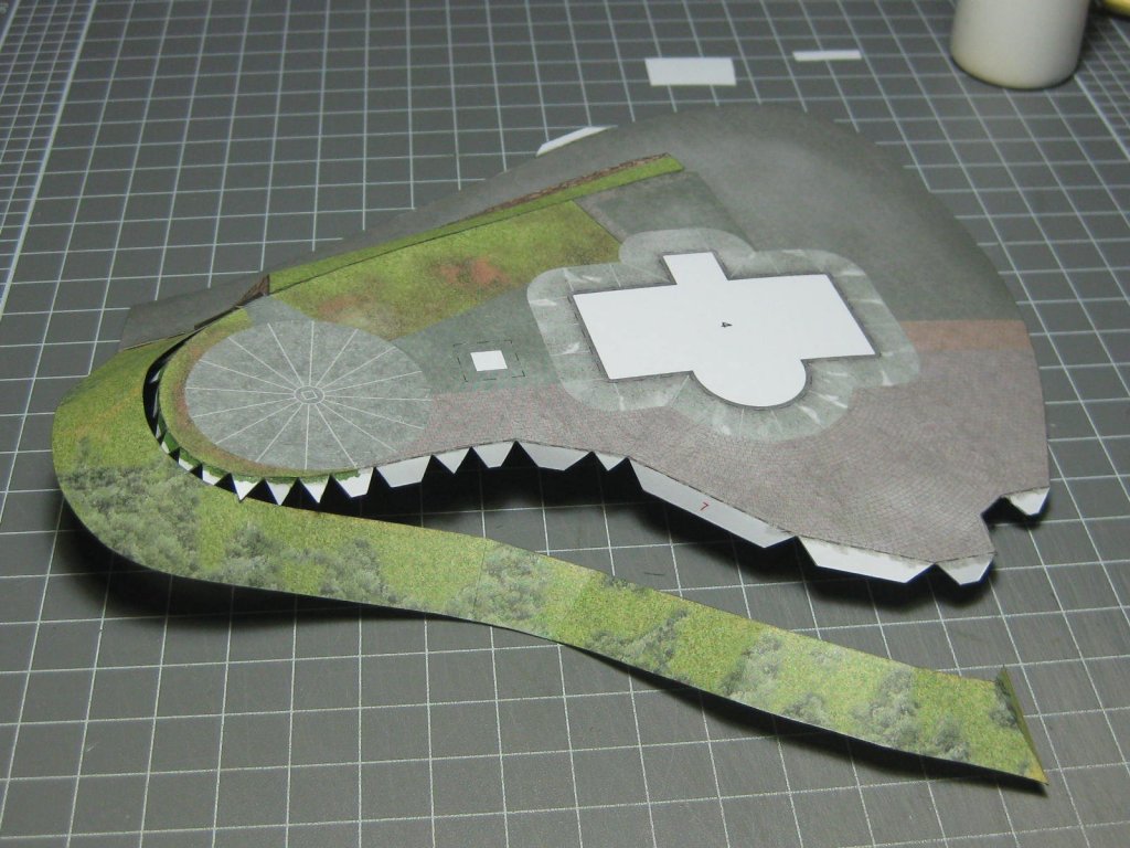
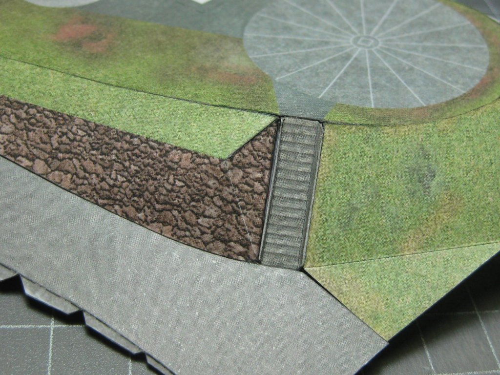
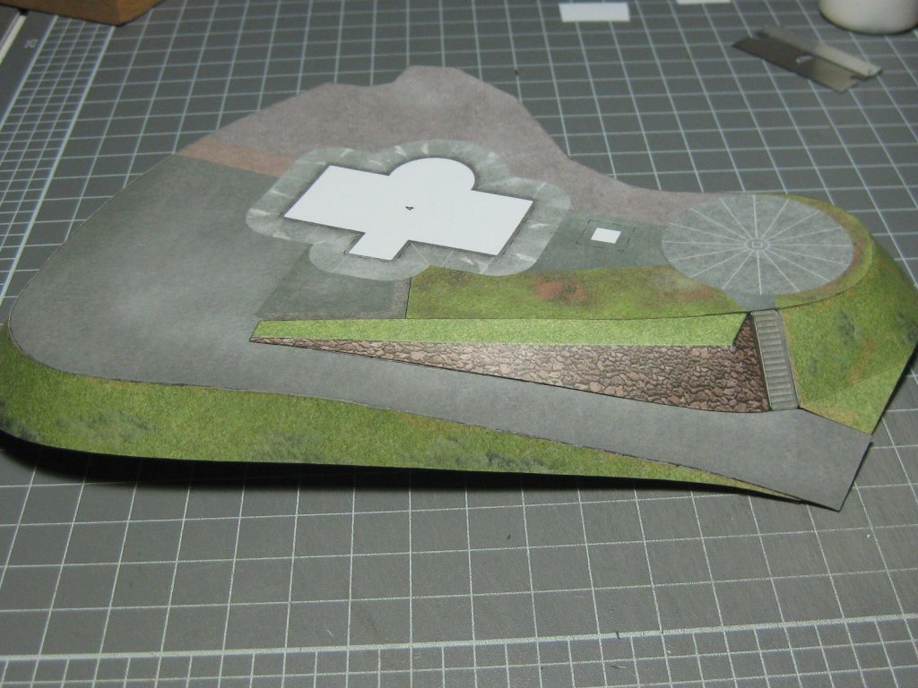
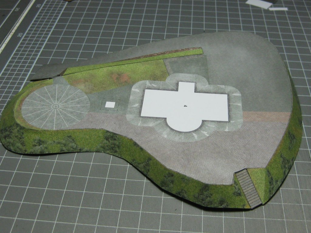
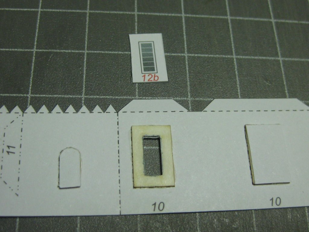
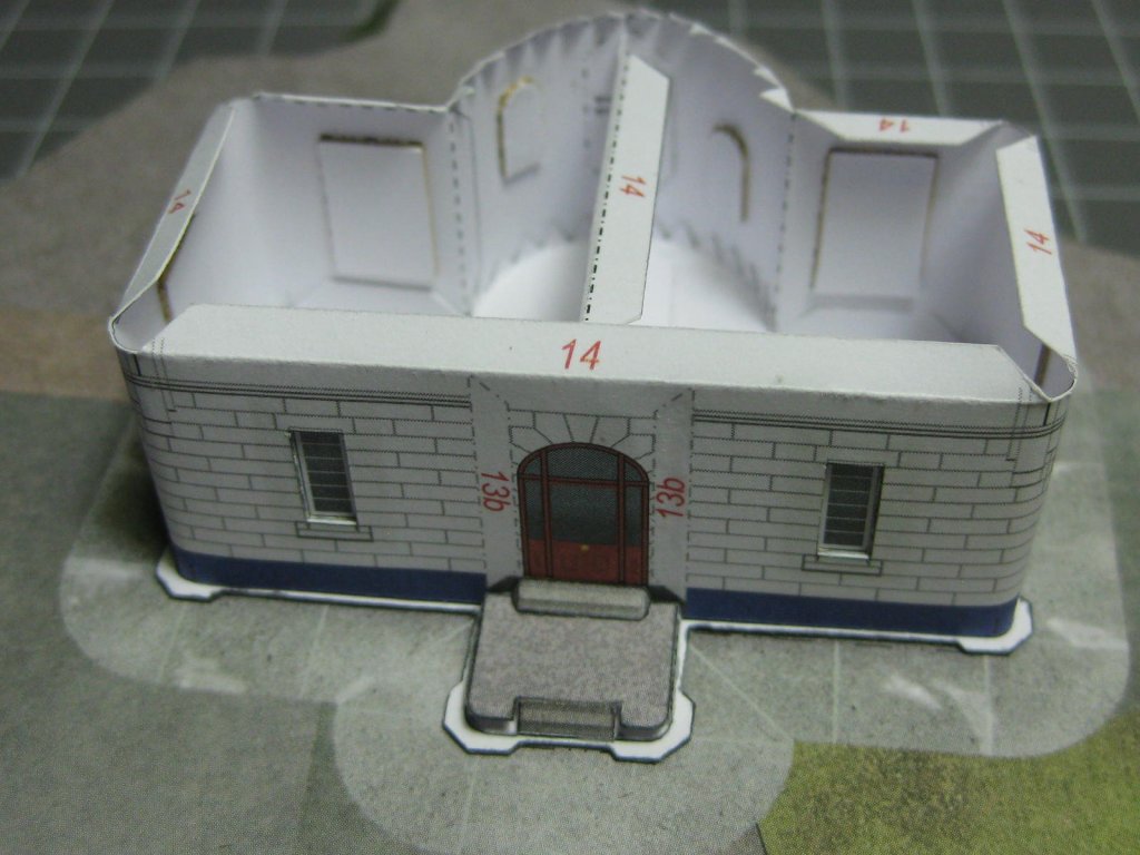
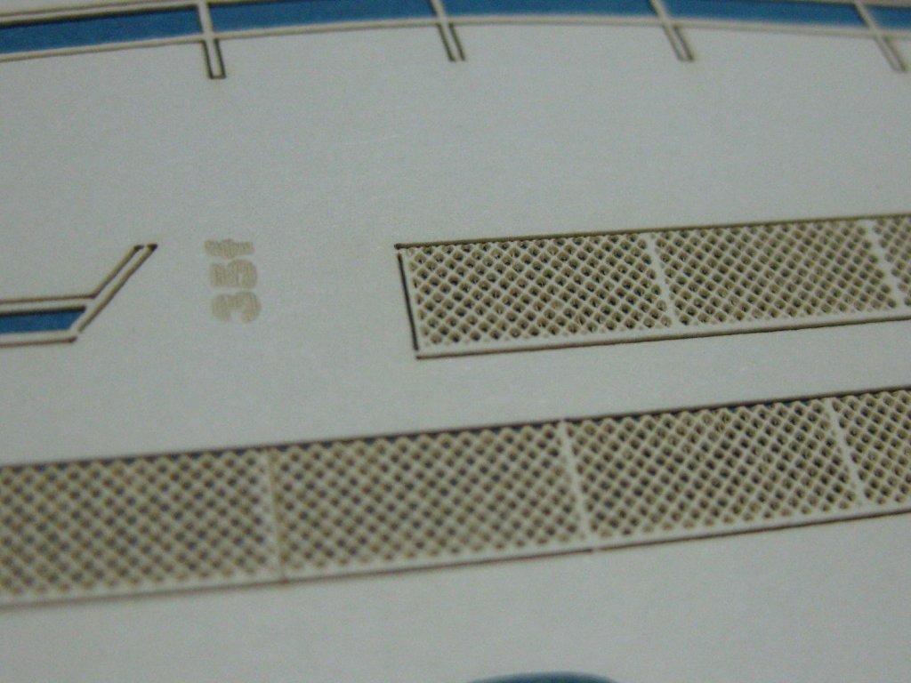
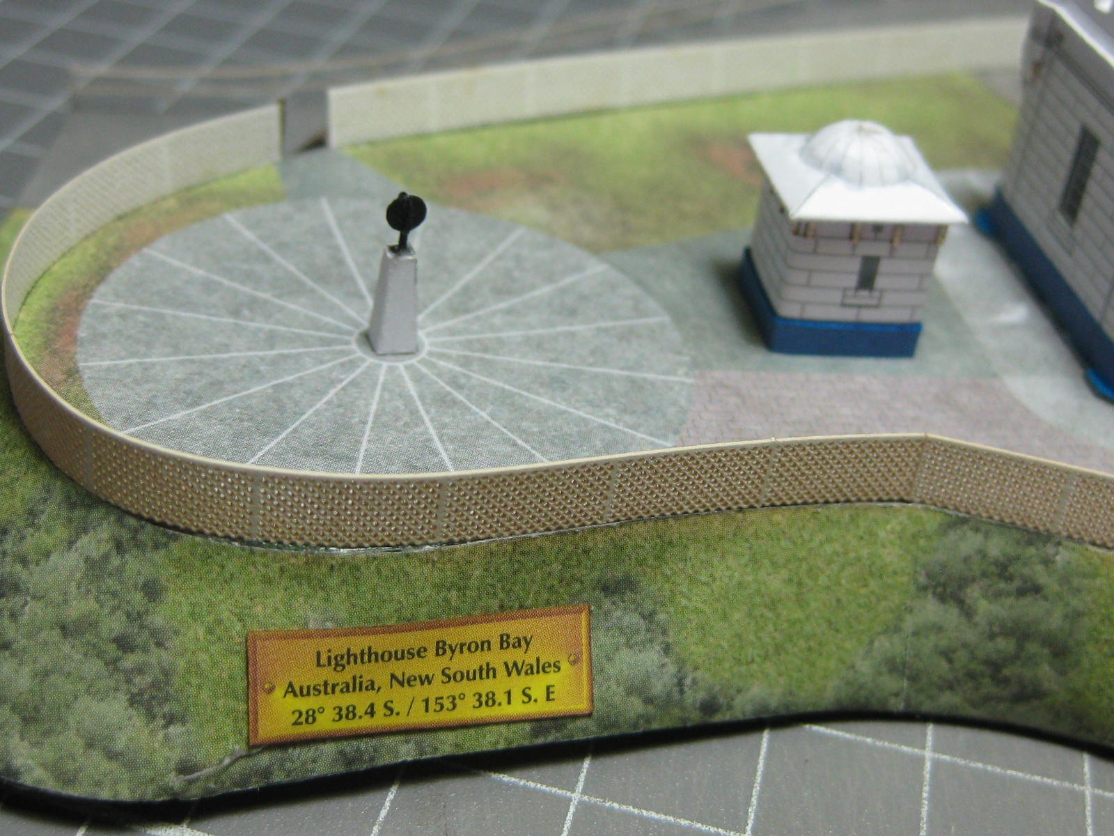
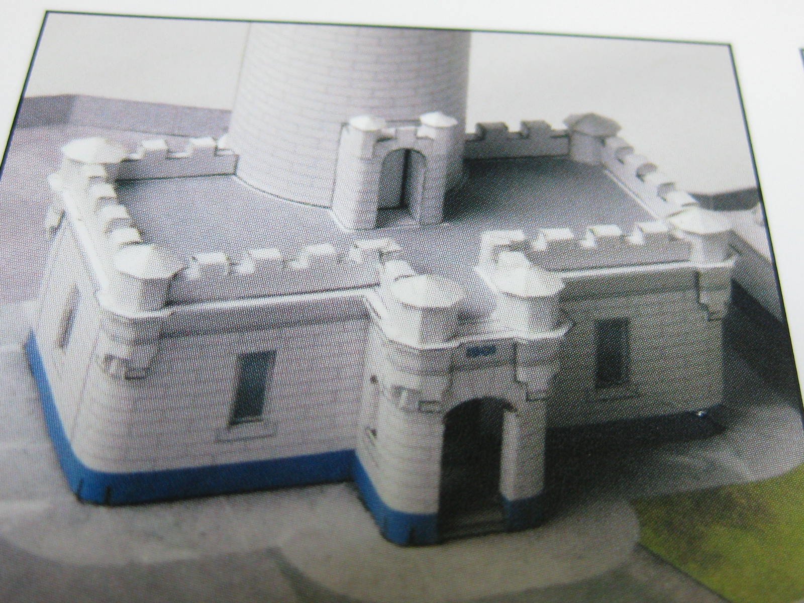
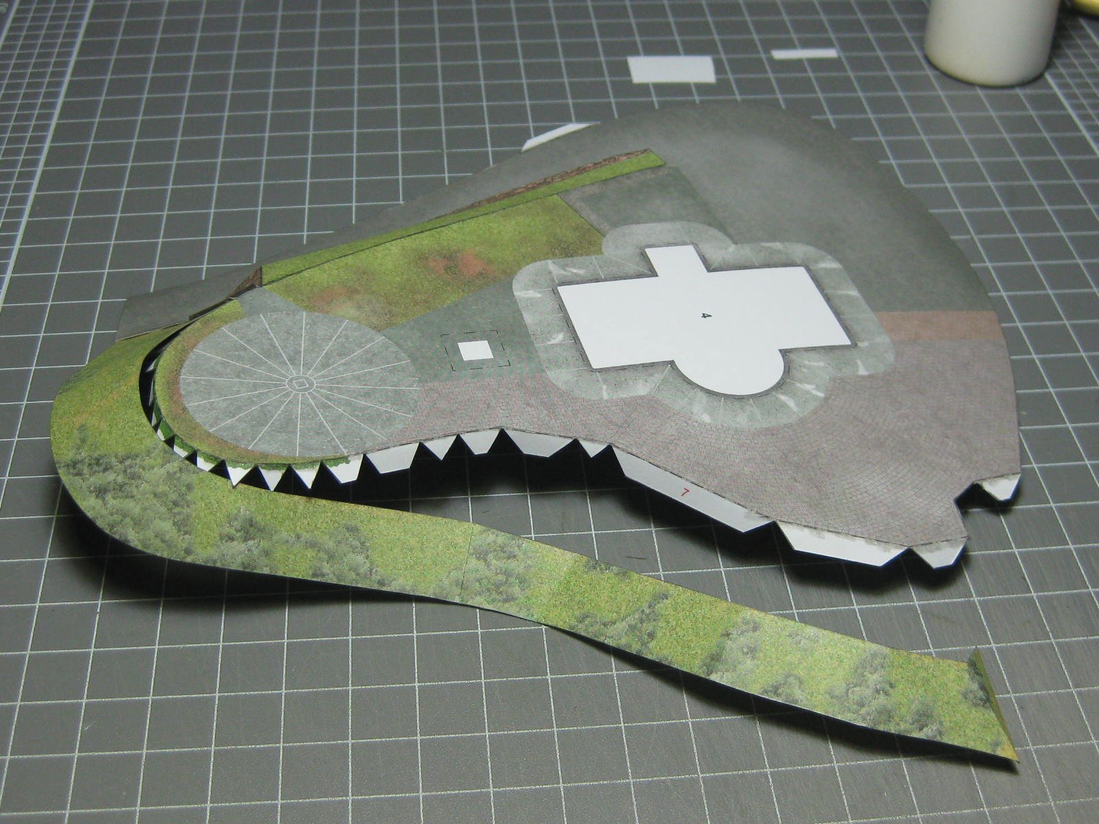
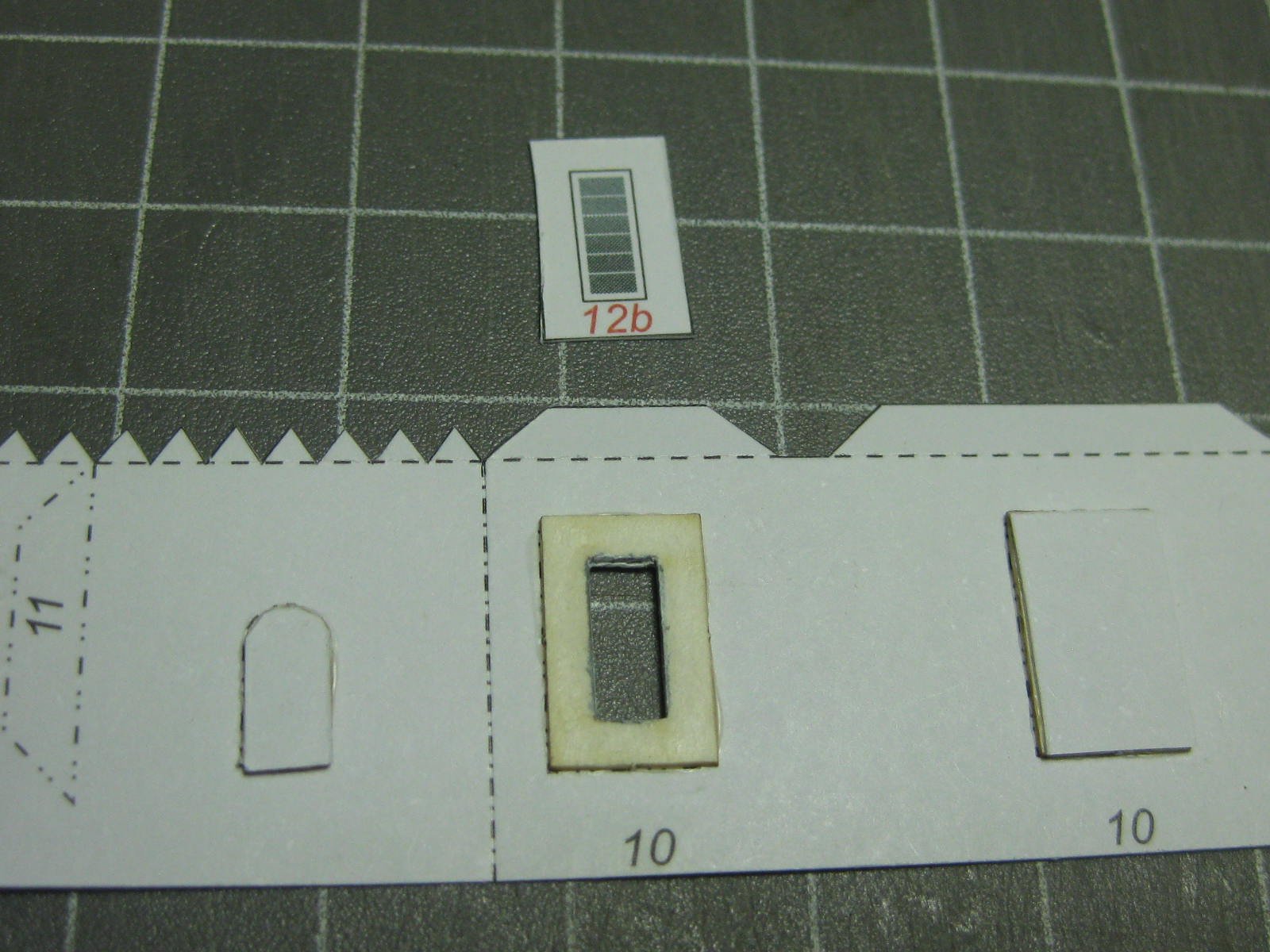
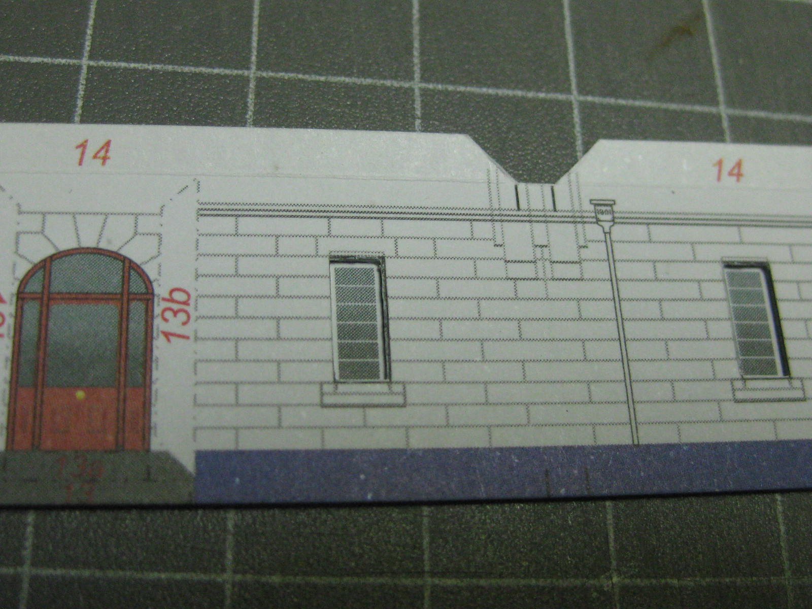
Hi all, I've taken a small break from my M1-24D Hind helicopter to make a present for my Admiral. It's a paper kit of the Cape Byron Lighthouse in NSW Australia. Here's a pic of the real thing : The kit is published by HMV (Germany) in 1:250 scale. The kit also has three other Australian Lighthouses, but I probably won't make them unless I find myself "kitless" at some stage. The kit is well printed and designed, even with the use of tabs. All the parts so far have fitted perfectly. The instructions aren't the best, but workable. The card it is printed on is good quality, although with a touch too much of a "plastic" feel when folding it. This makes crisp folds a bit more difficult than usual. I also bought the optional laser-cut sheets which contain some really tiny parts and some great-looking mesh railings : These pics are from the kit of a finished model : First thing to make is the base, which has grassed areas and a car ramp : The windows are recessed to give a feeling of depth : The lower section : A decorative moulding is on each external corner : Danny


- 16 replies
-
- 18
-
-
Yeah, no worries. As long as you can afford my rates of $150 per hour (kidding ). Fenten's in Brisbane have the Bussard/Falke kit with 5 B&V 138's (in 1/250 scale) for $AU16.00 plus postage (about $8.00). Just a thought, the ship itself looks interesting. Hmmmm....... Danny
- 345 replies
-
- 4
-
-
- graf zeppelin
- trumpeter
- (and 2 more)
-
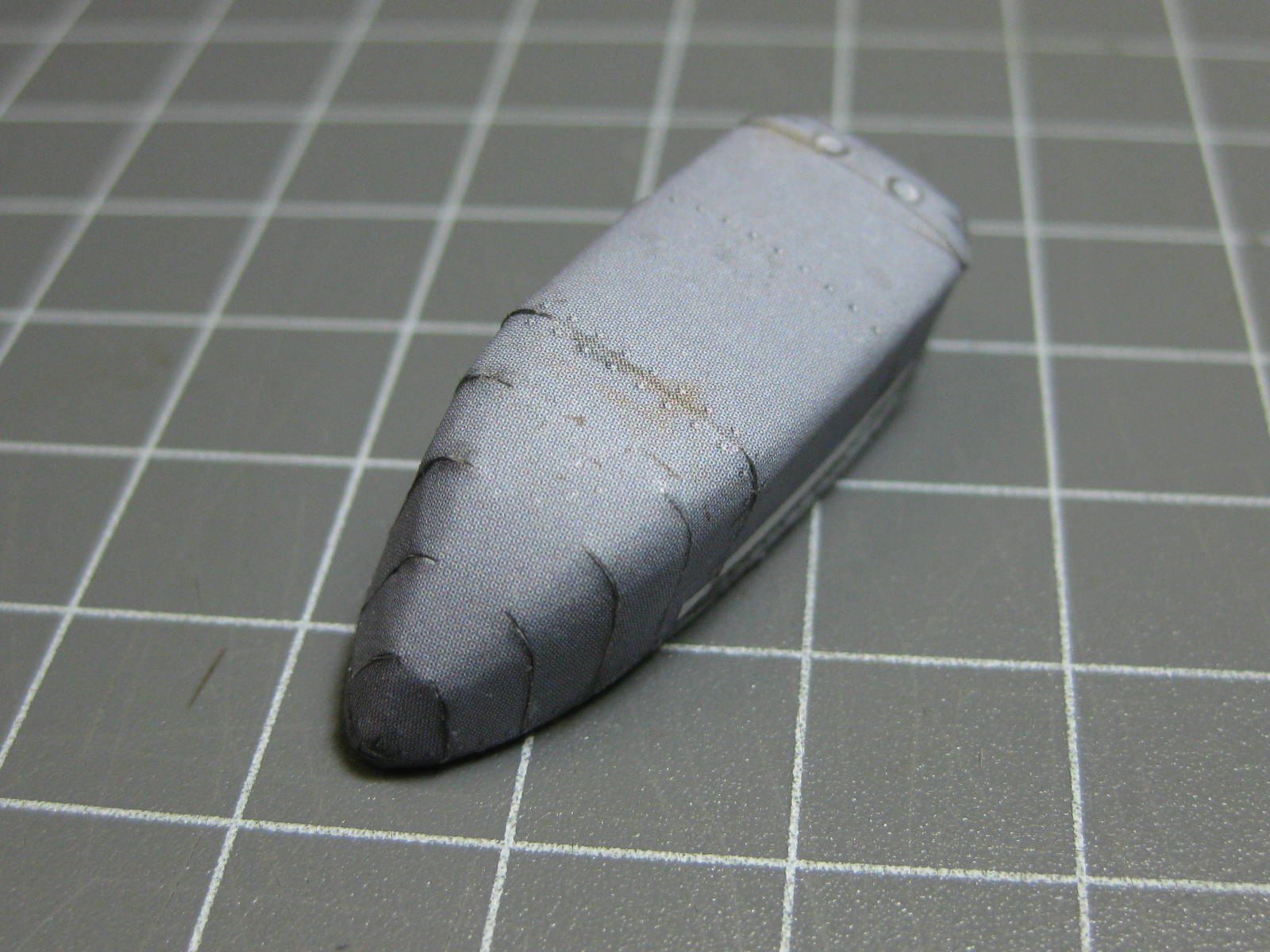
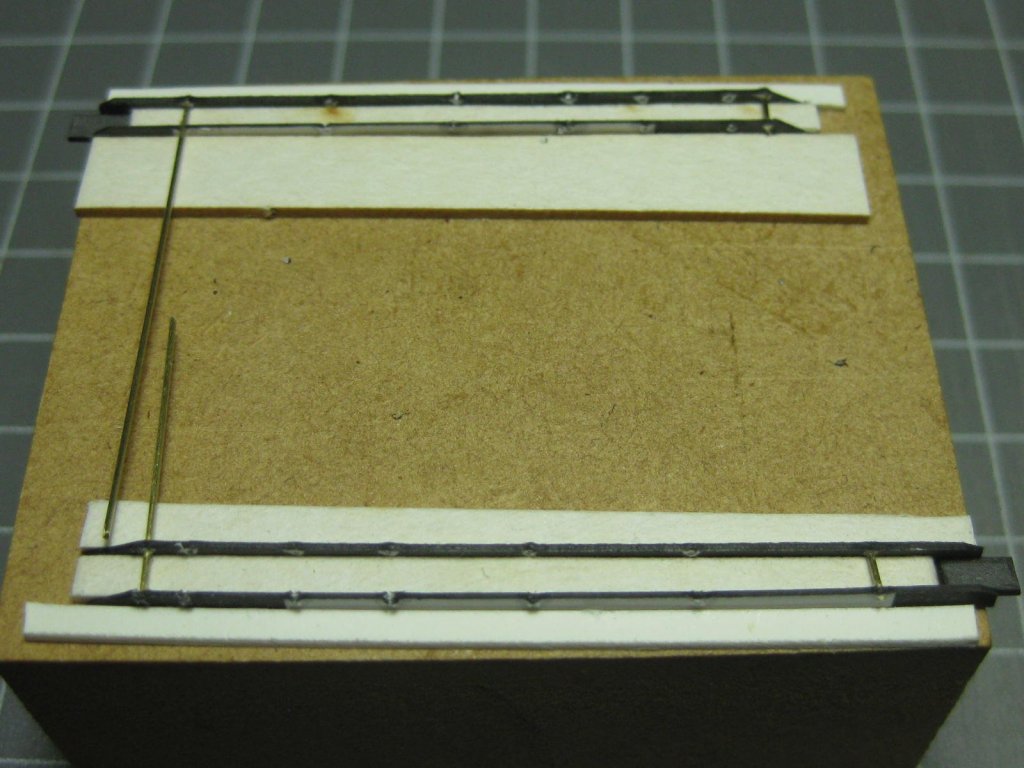
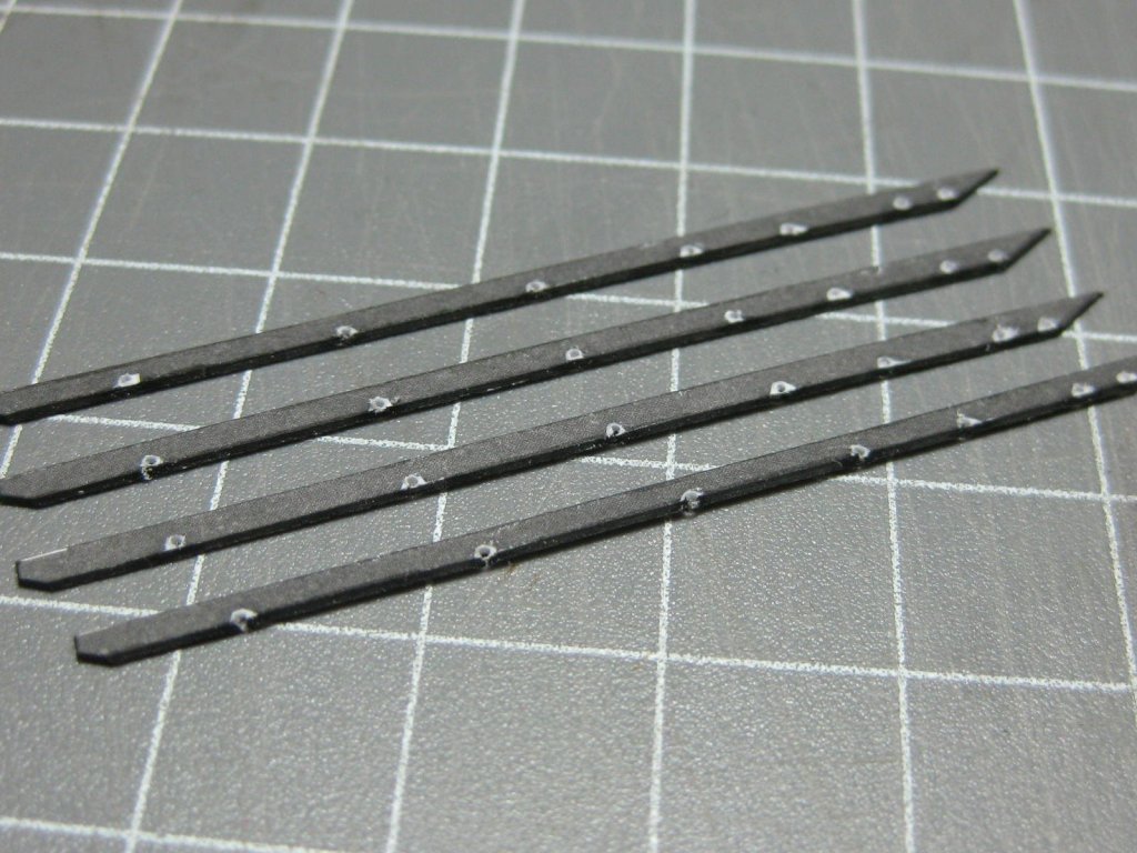
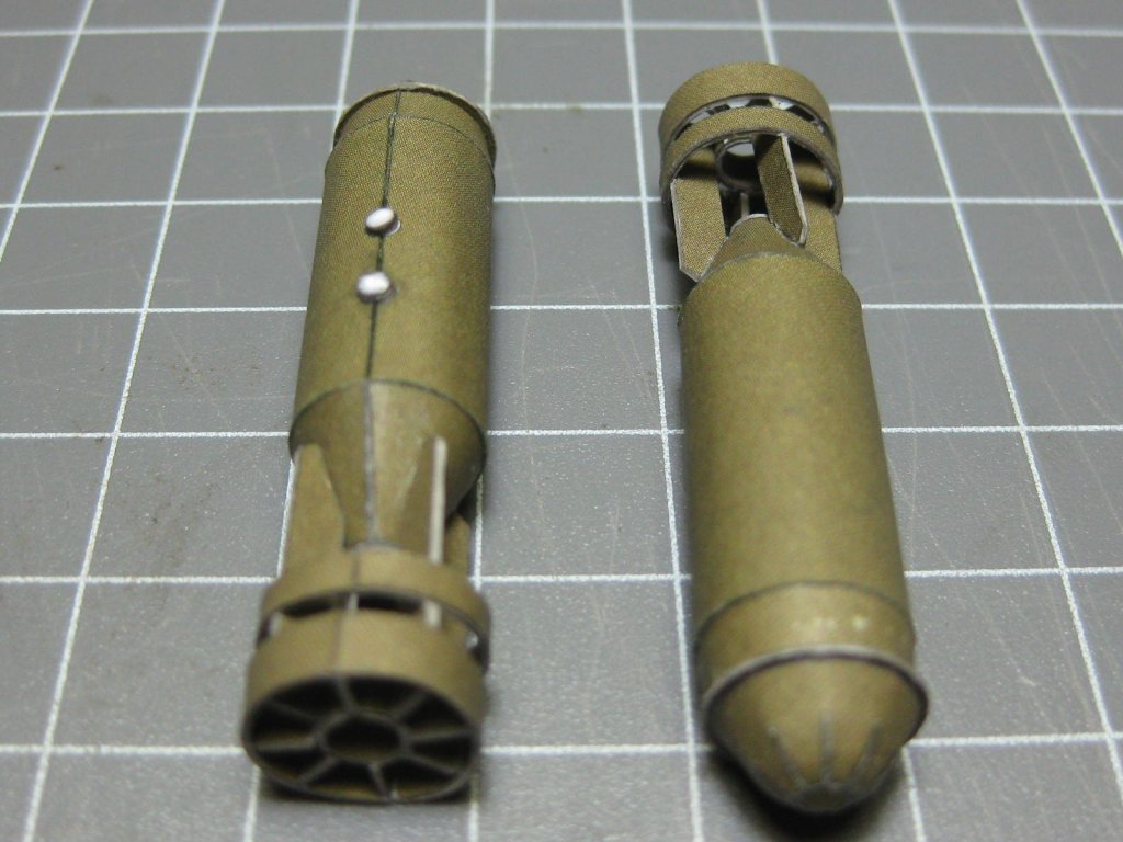
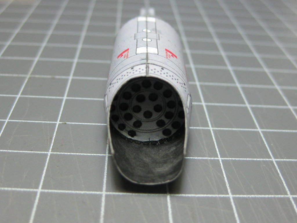
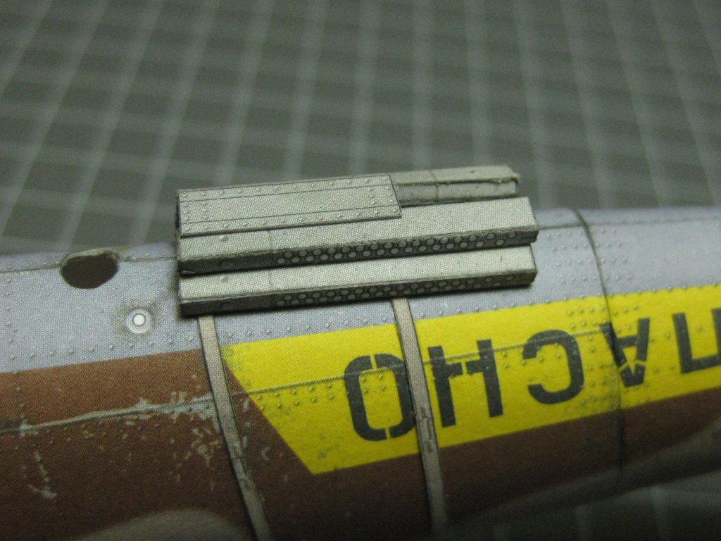
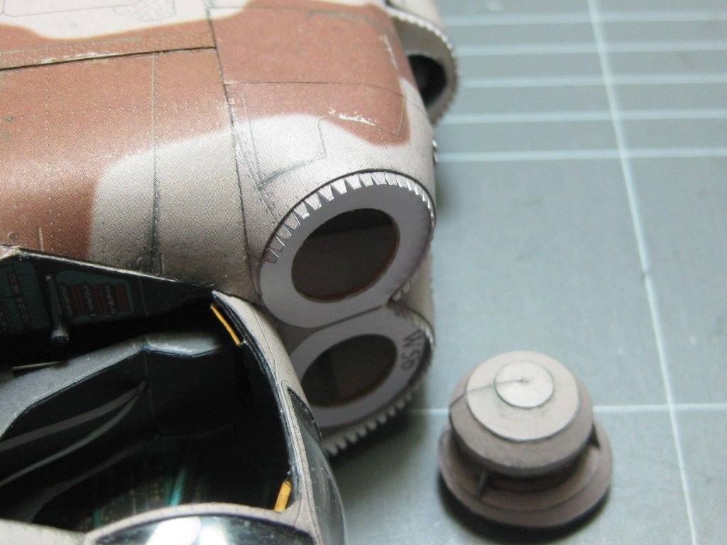
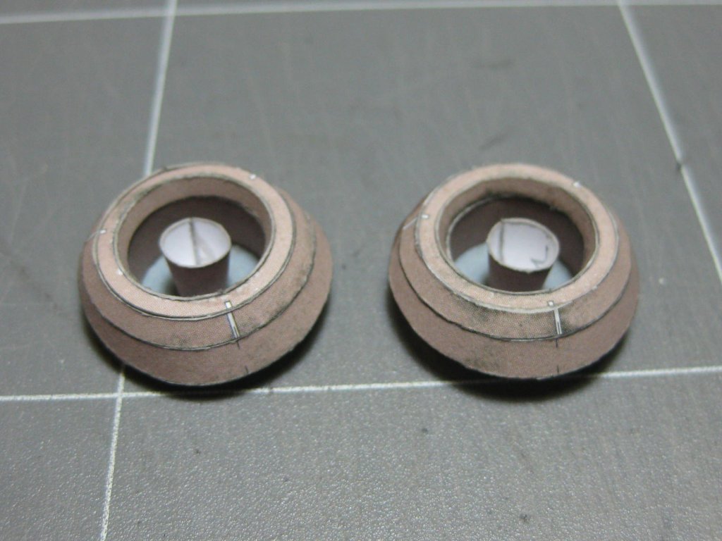
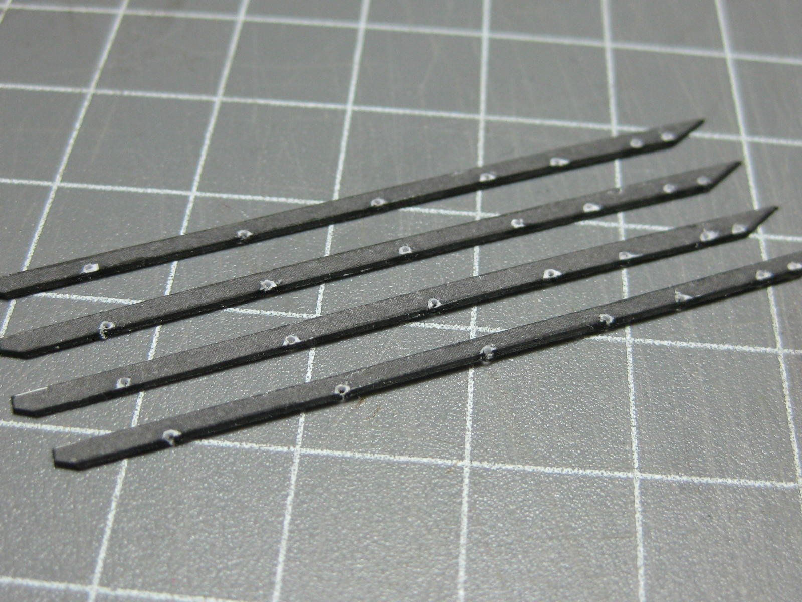
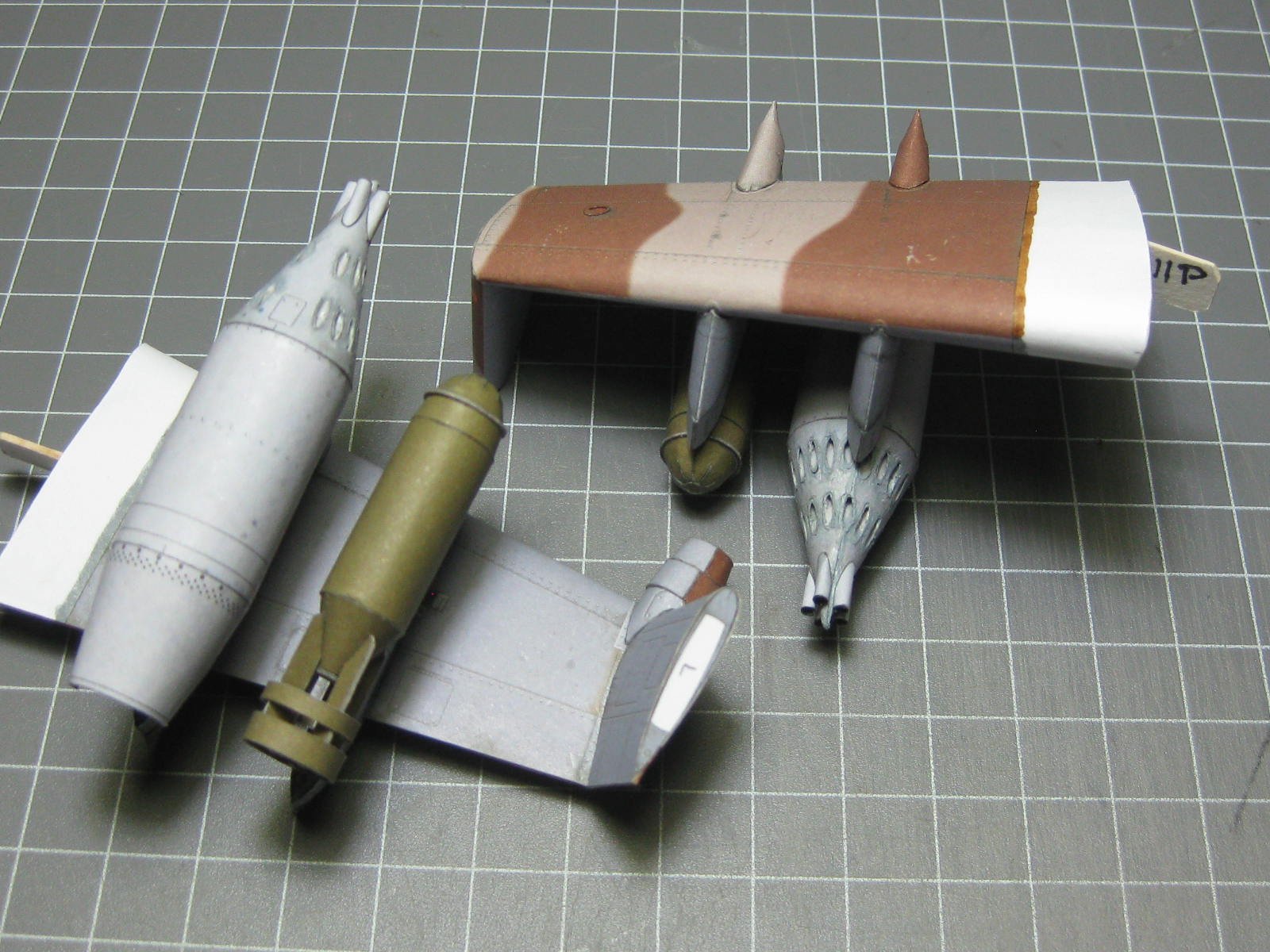
The inside of the rocket launcher needed to be painted, one of the very few bits of this kit that could have been designed better : The launchers fitted to the wings : The two bombs were an enjoyable step : Again, there is a mistake in the kit. The outer side of the rings should have had a coloured piece fitted. I used some left-over card from the two bombs that I wasn't going to fit to fix the problem : The nose cones came out the best of any rounded pieces I've done so far : The bombs fitted : The four missiles use a mounting bracket. These are a rather involved unit, as there are 28 pieces of wire holding the inner part to the other which needed 56 0.5mm holes drilled right on the edge of the parts. This step took me 3 hours : More pieces of the brackets : I made a jig to assemble the rails : Danny


- 127 replies
-
- 14
-
-
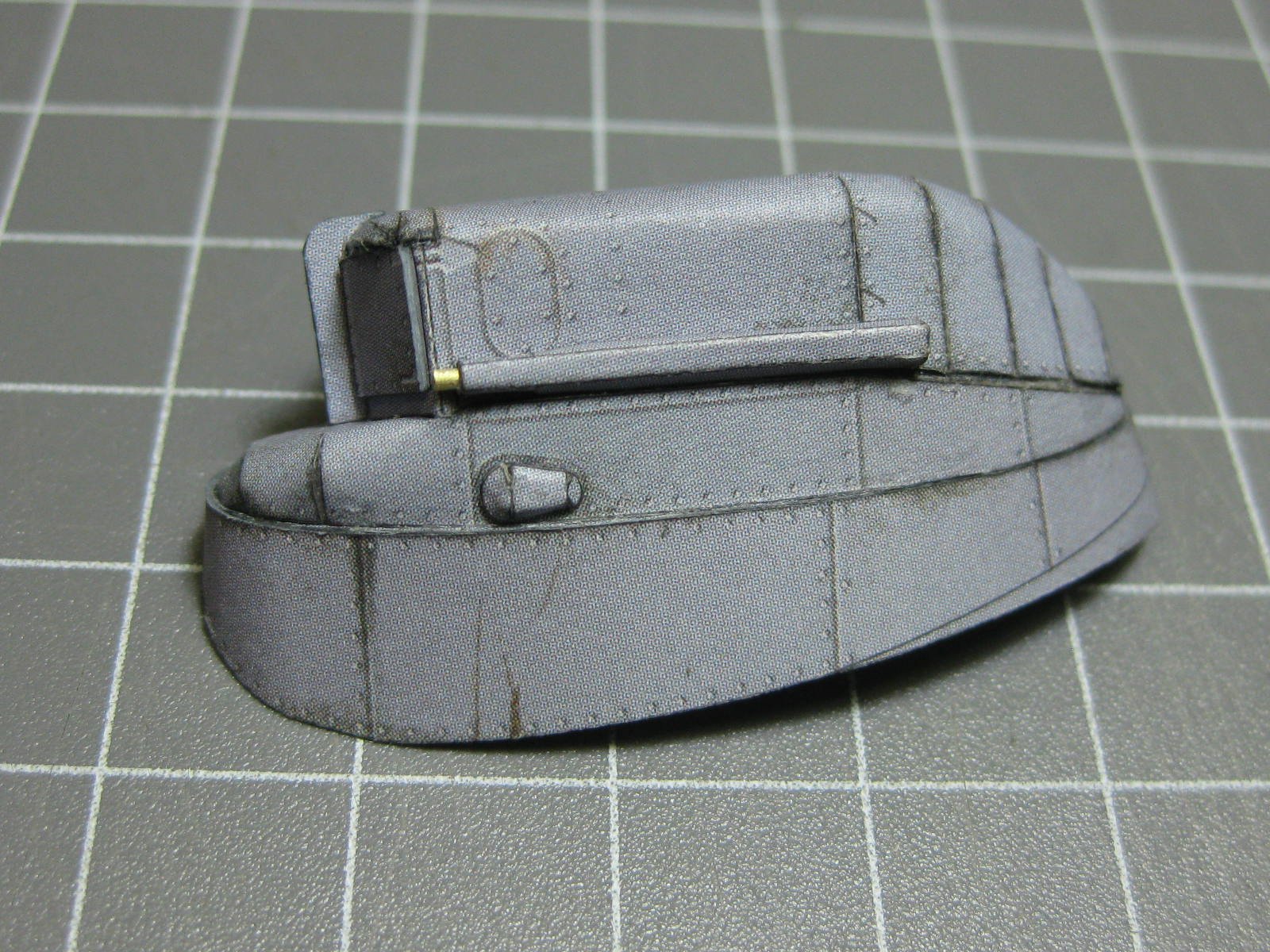
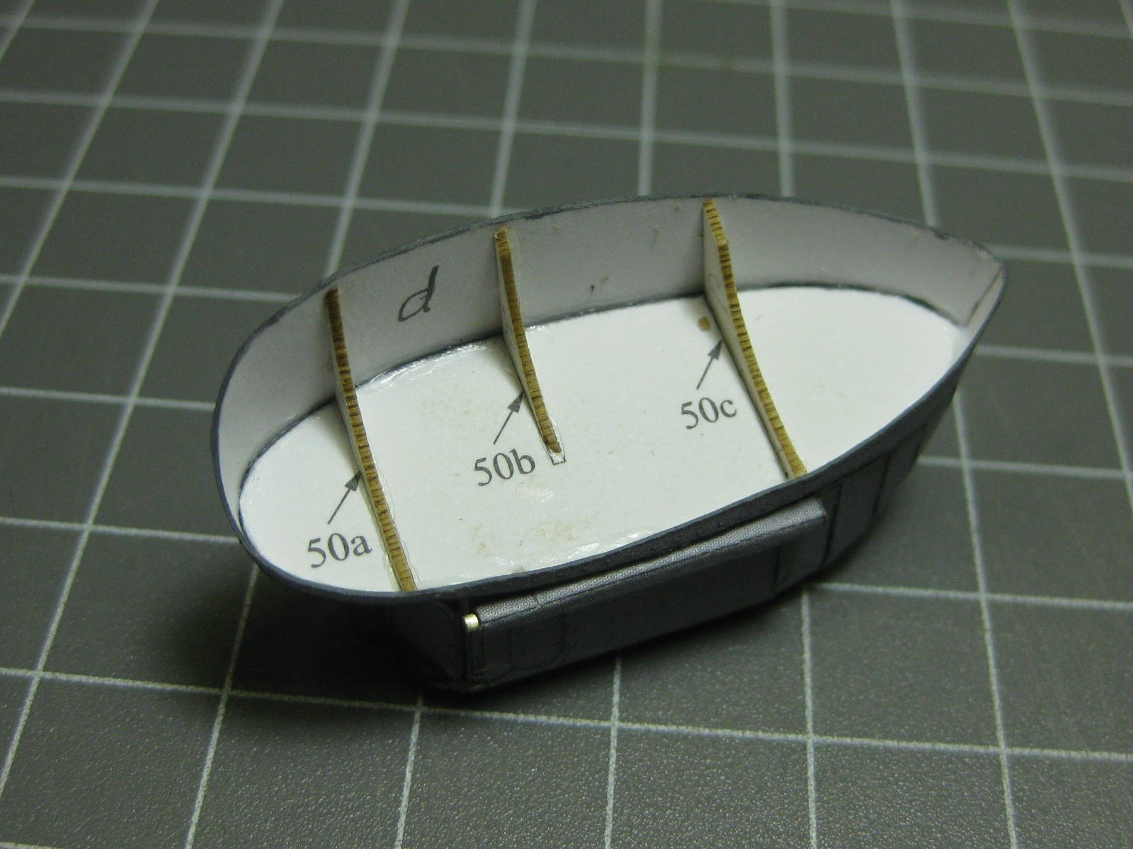
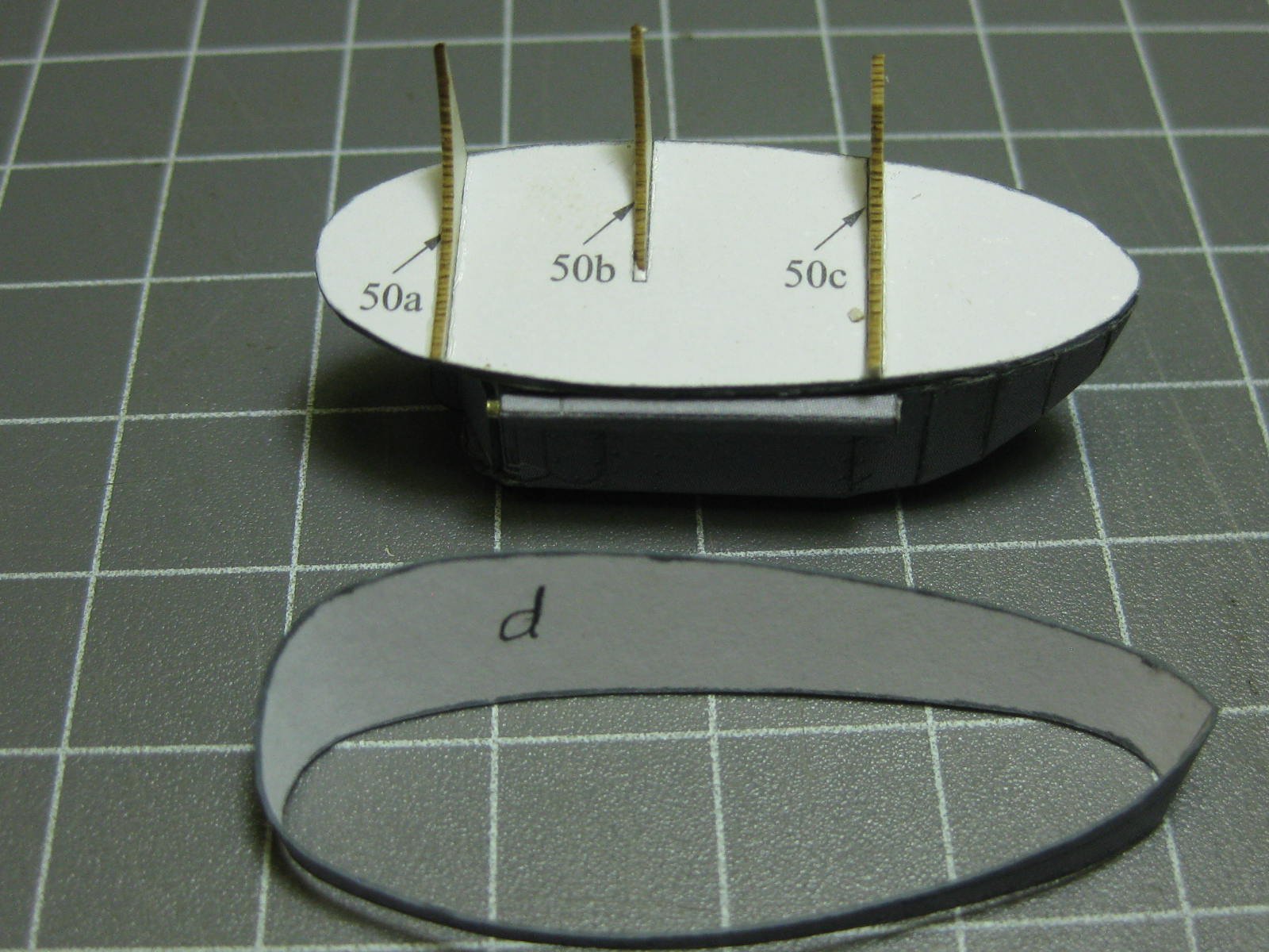
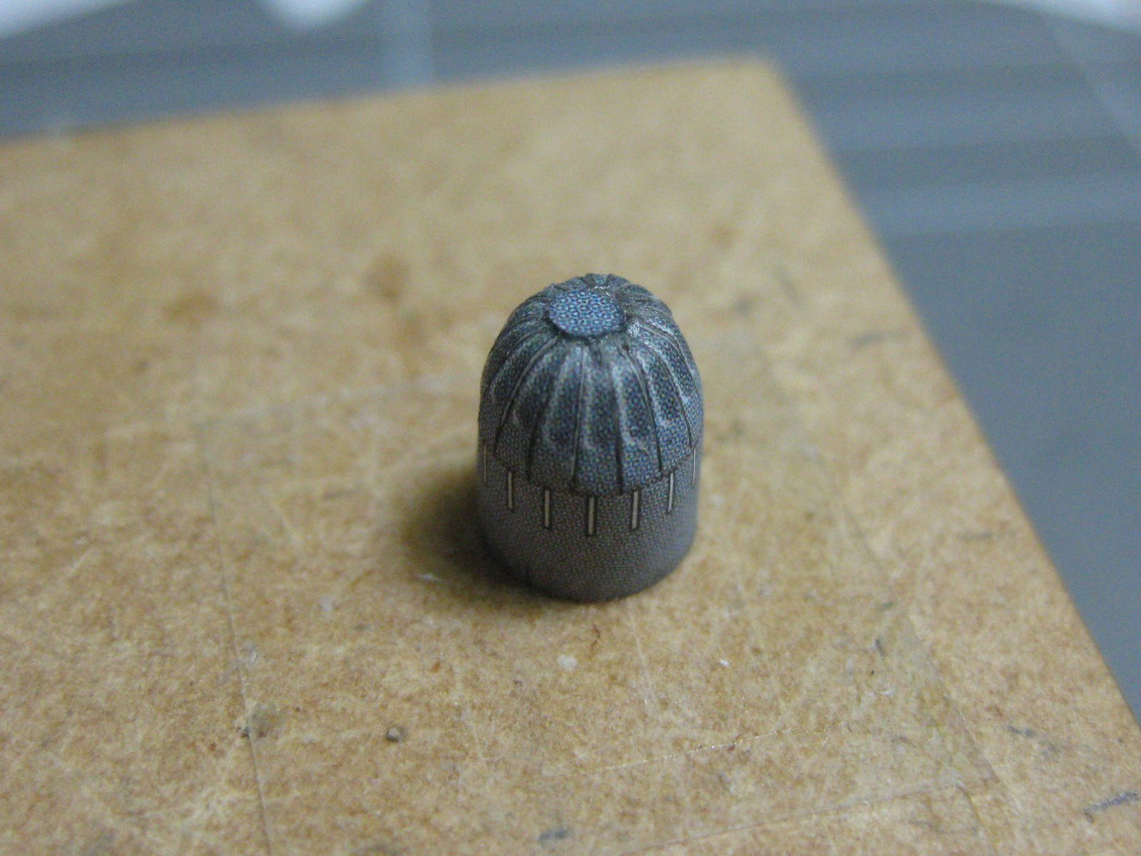
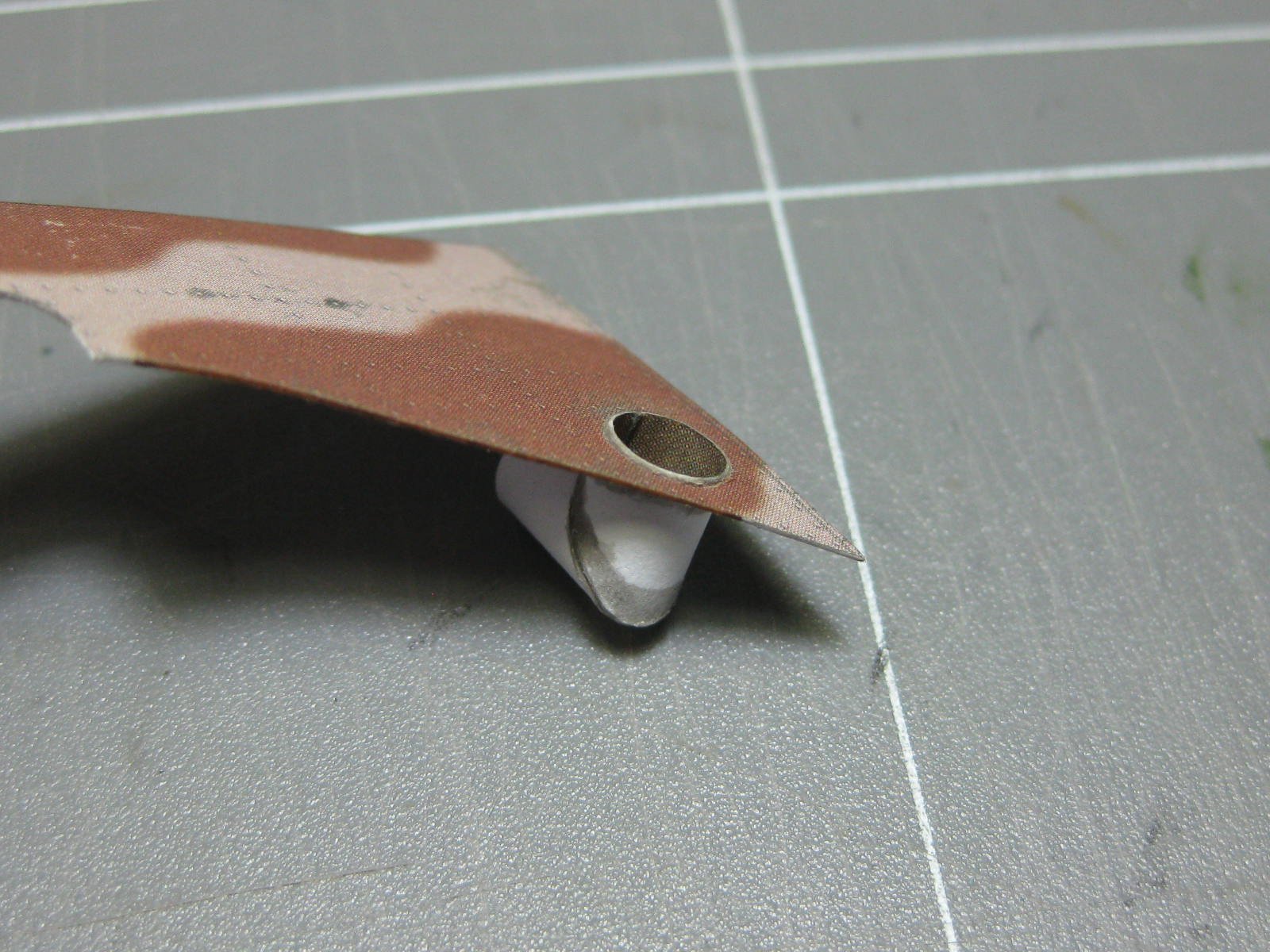
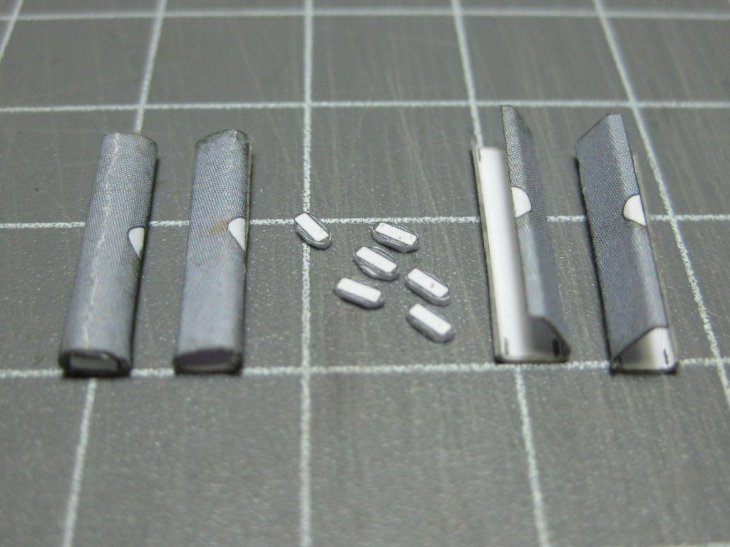
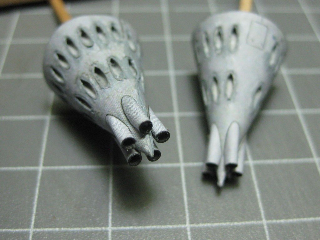
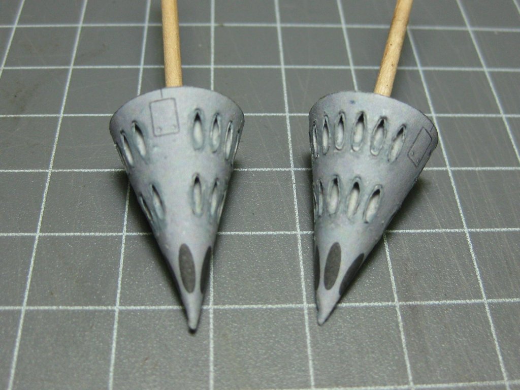
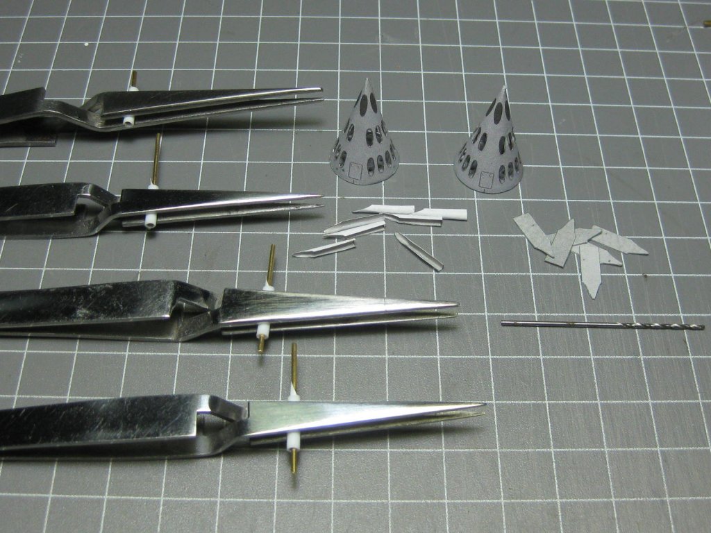
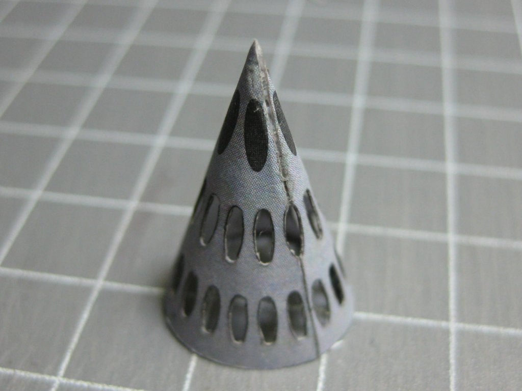
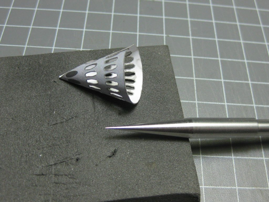
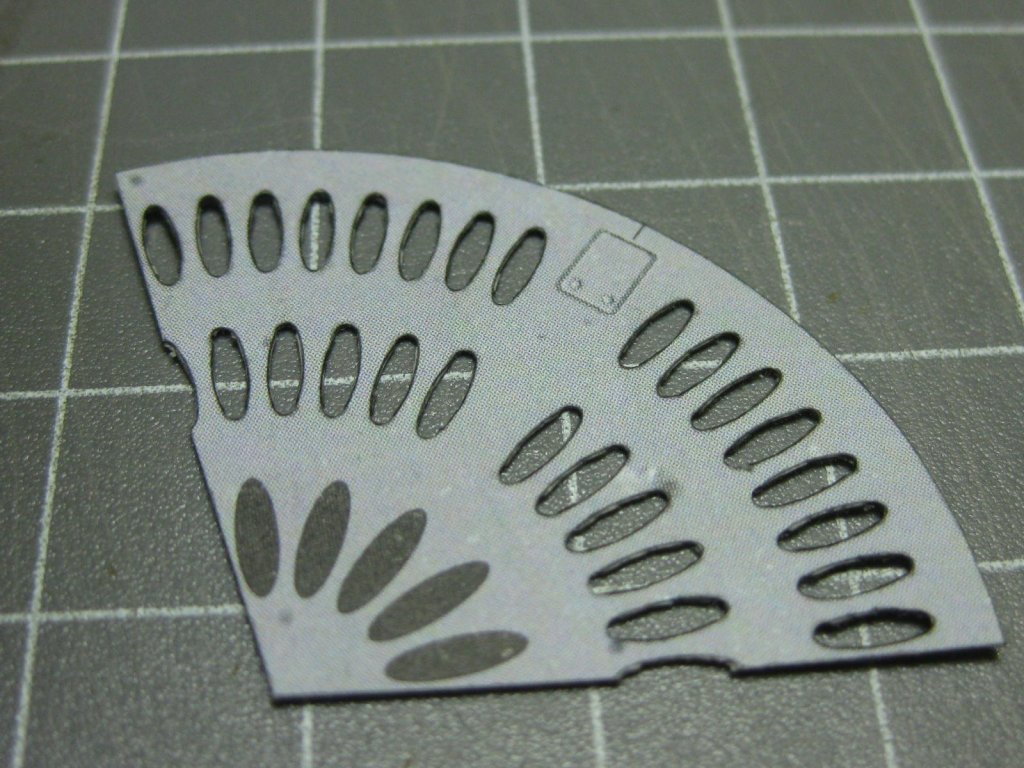
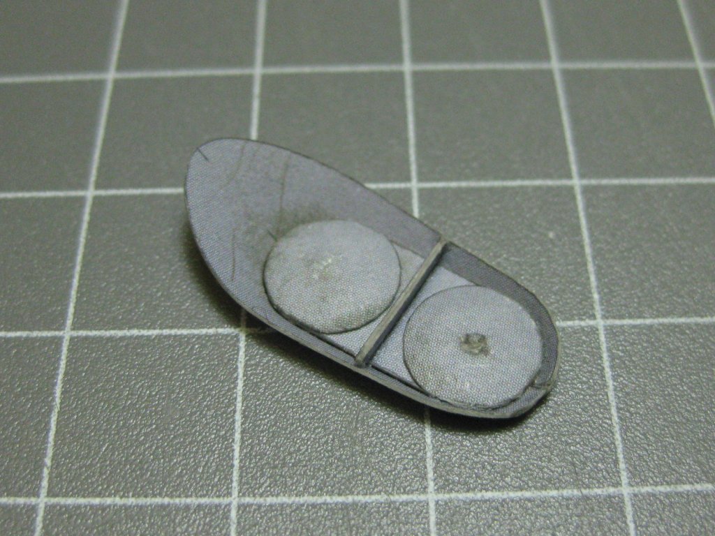
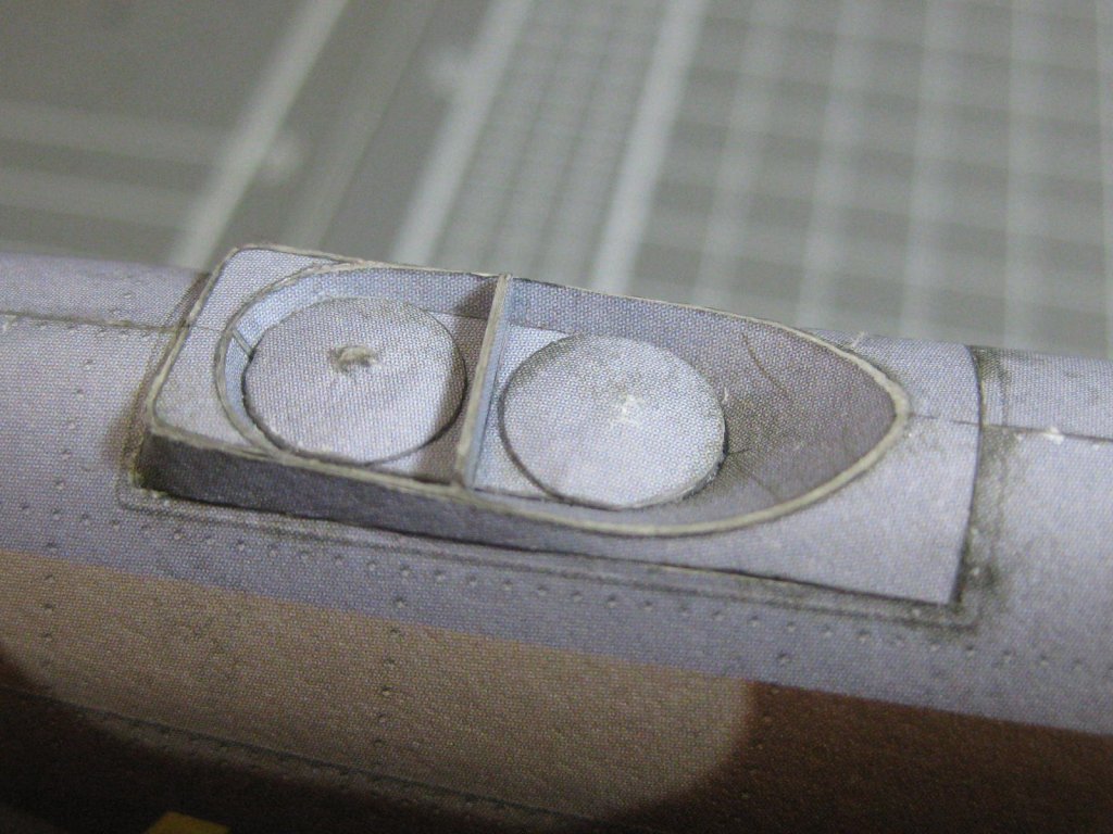
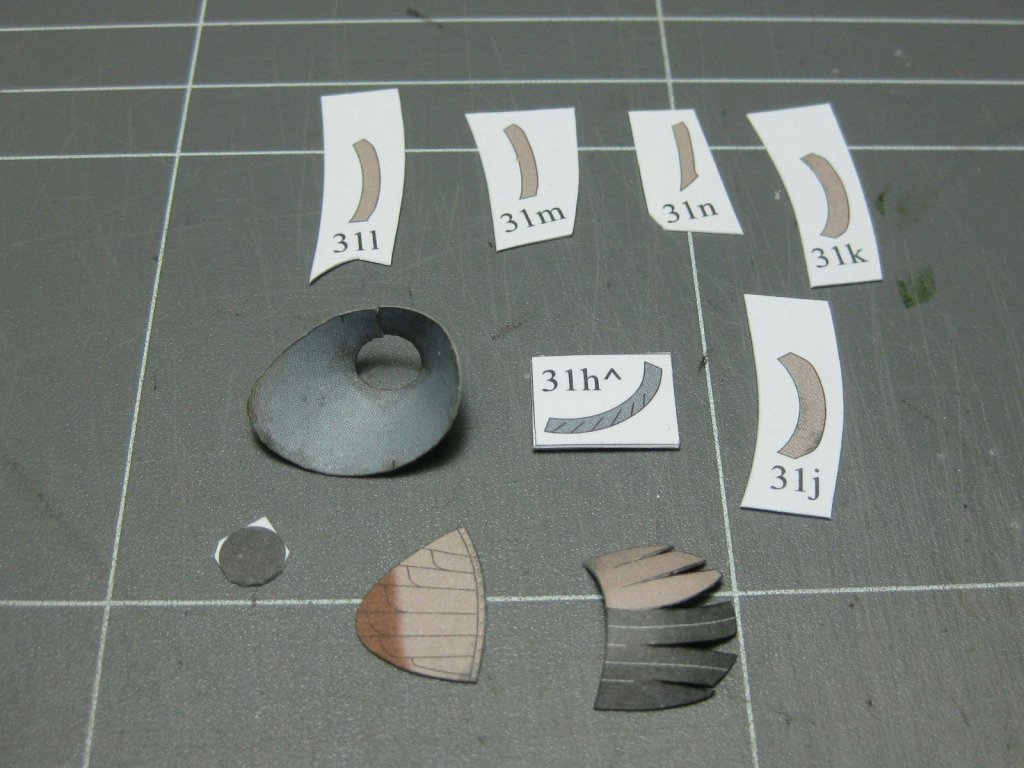
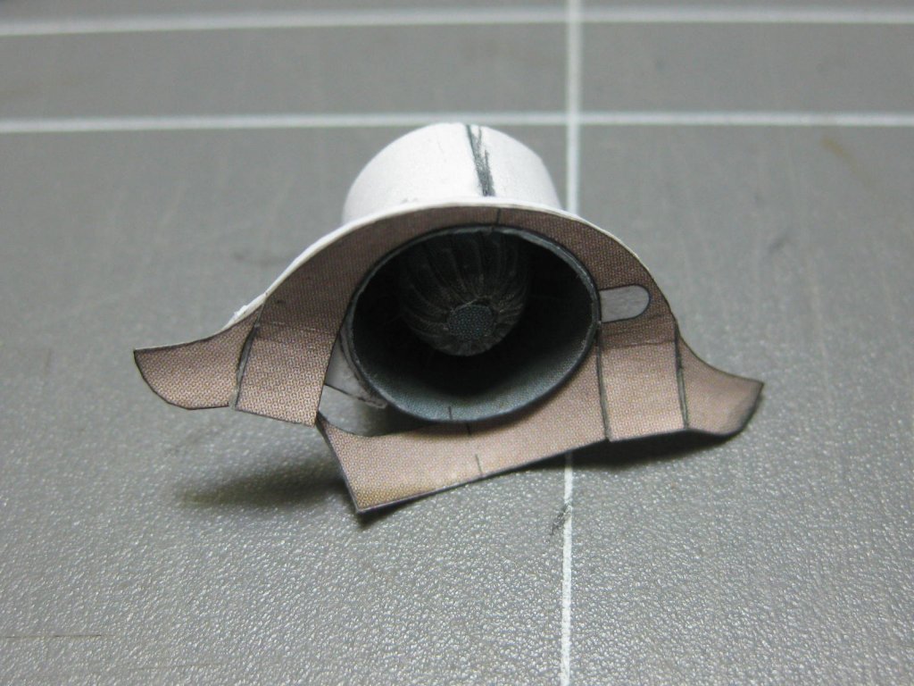
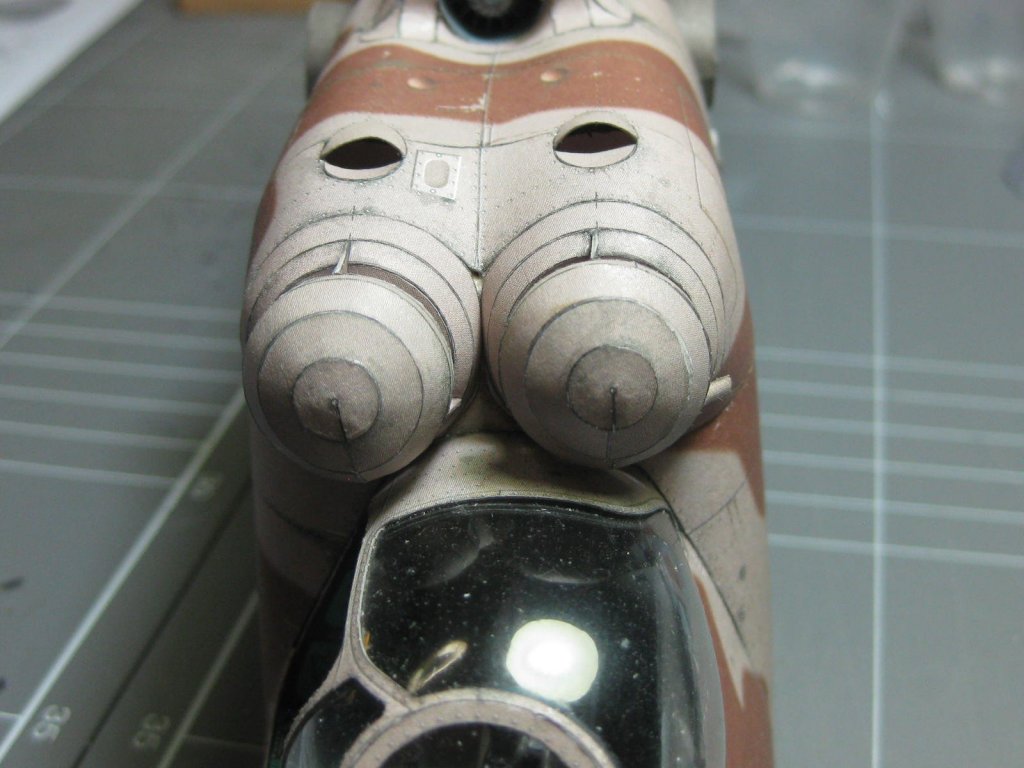
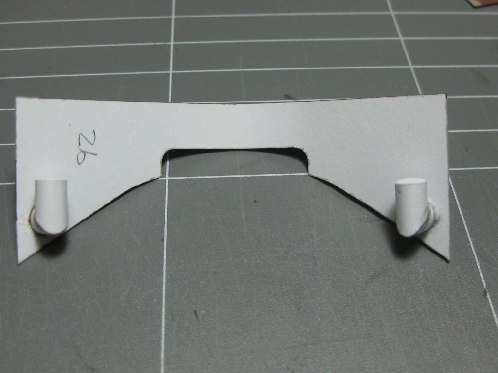
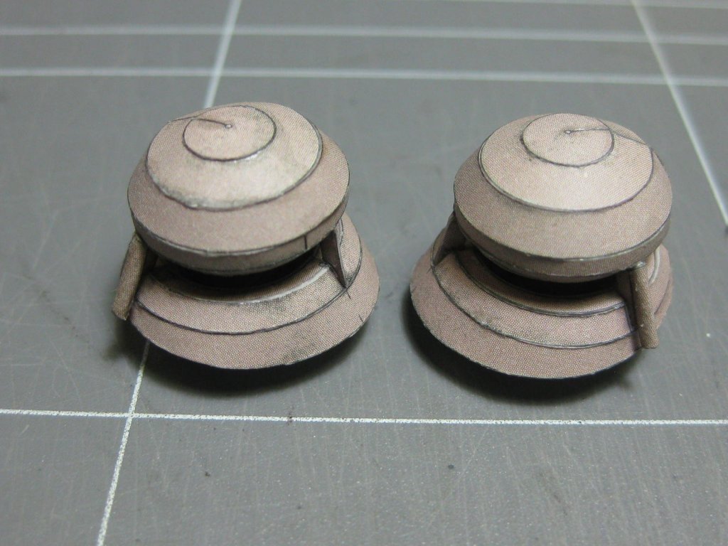
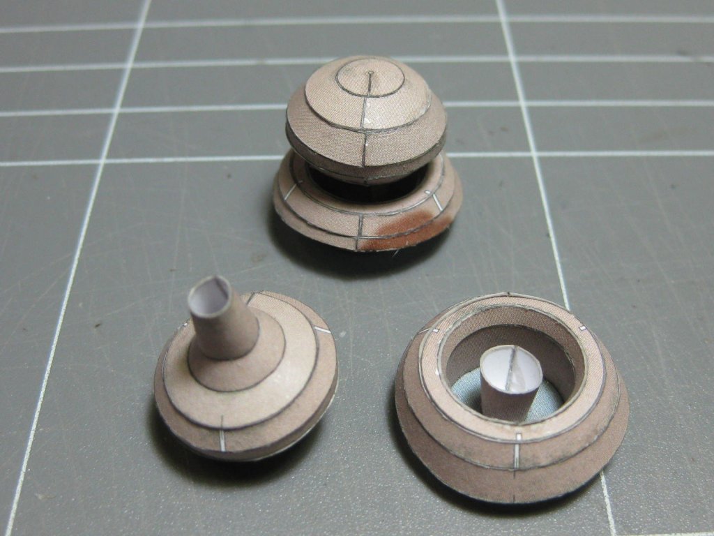
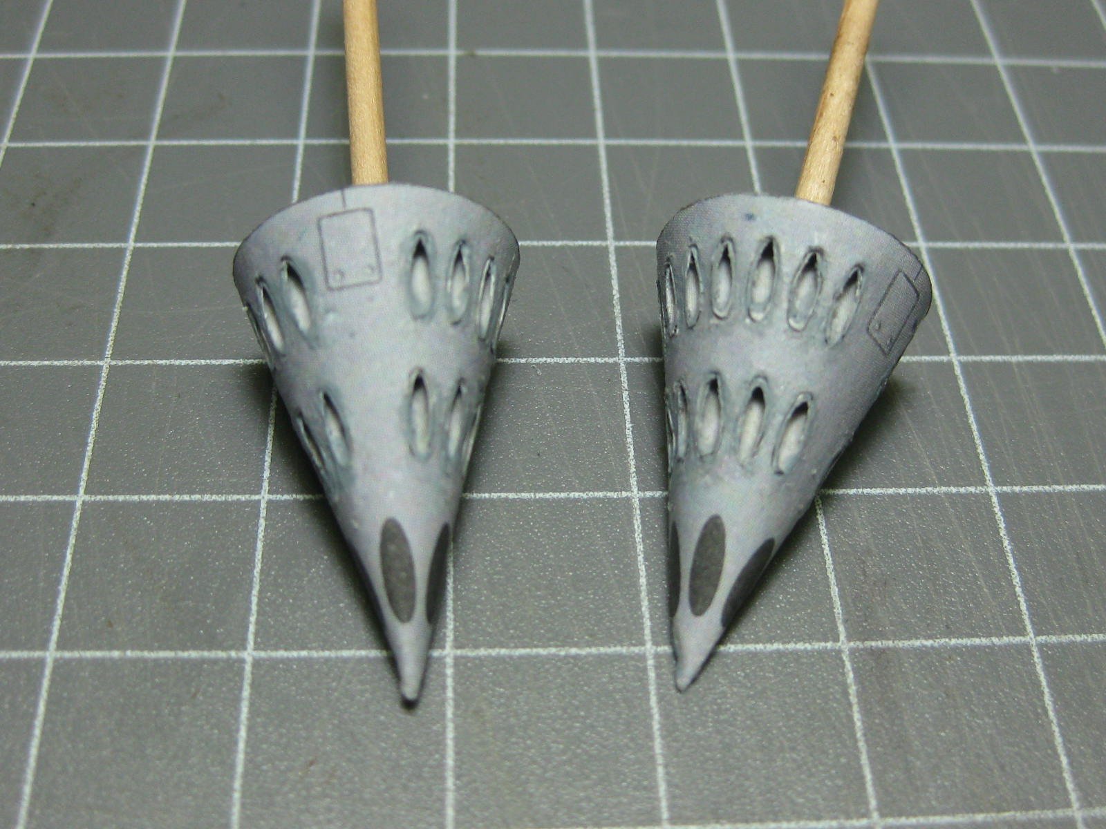
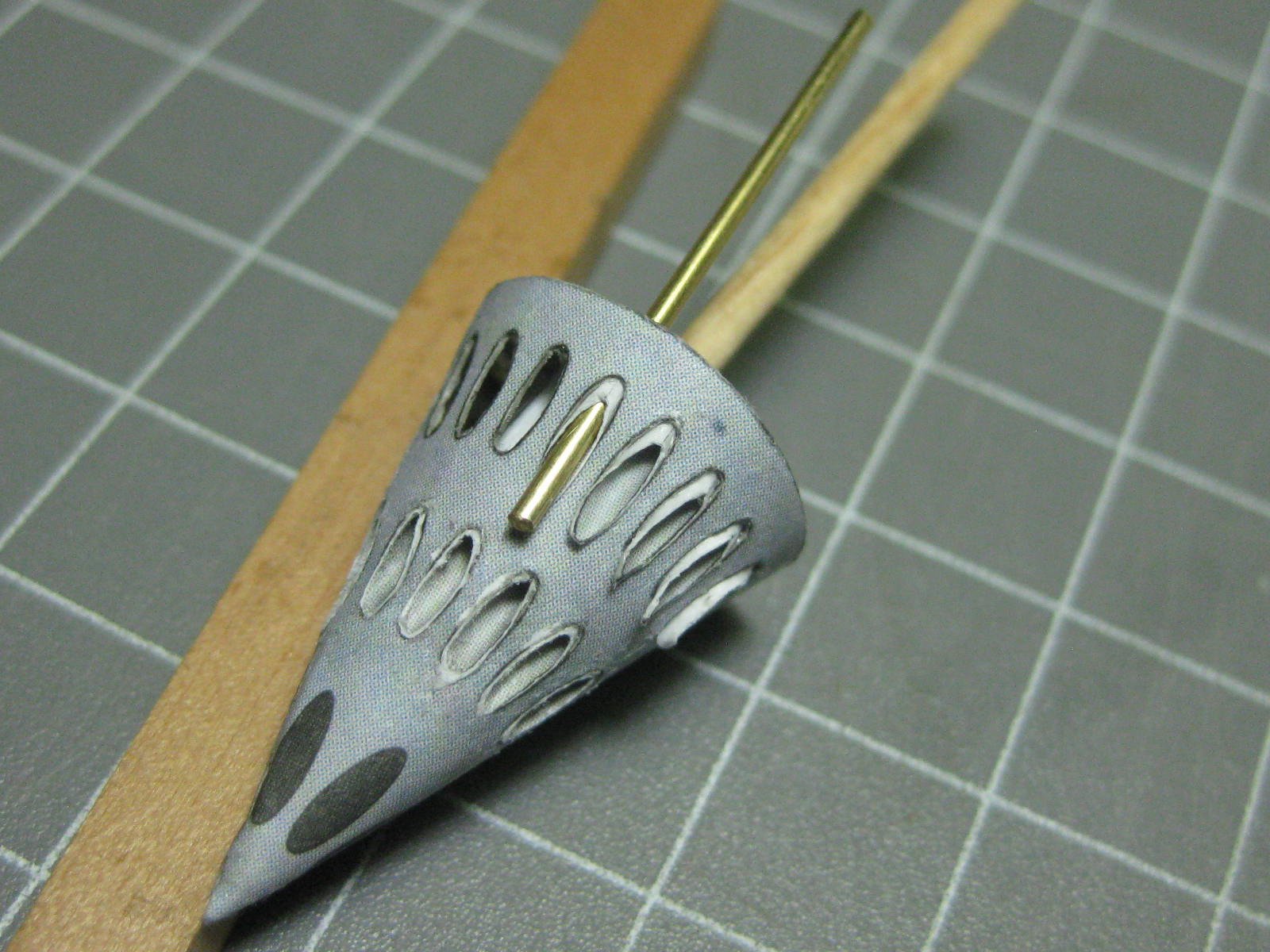
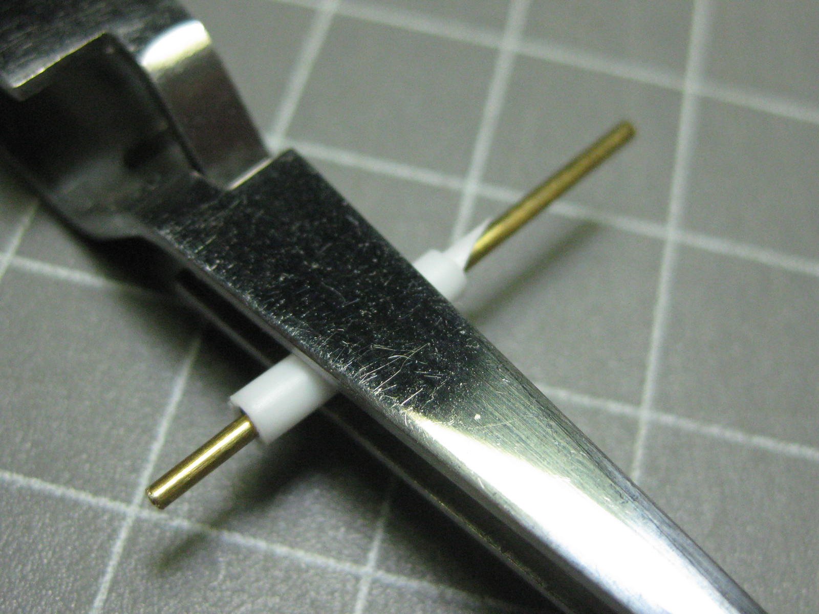
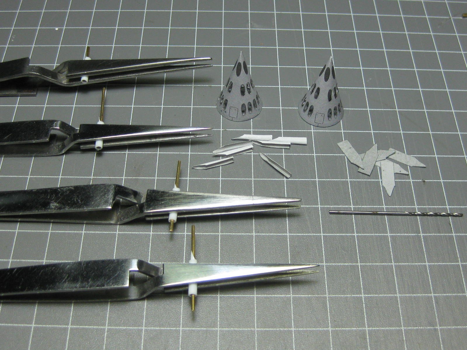
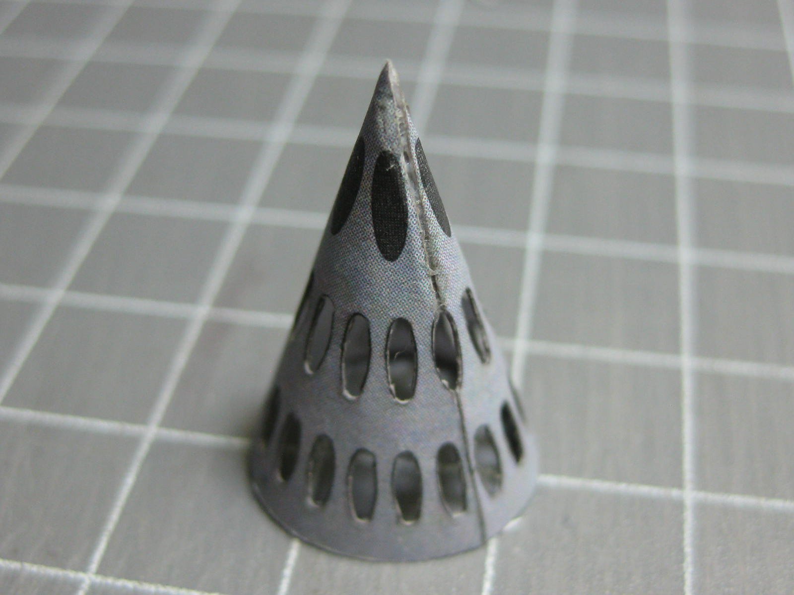
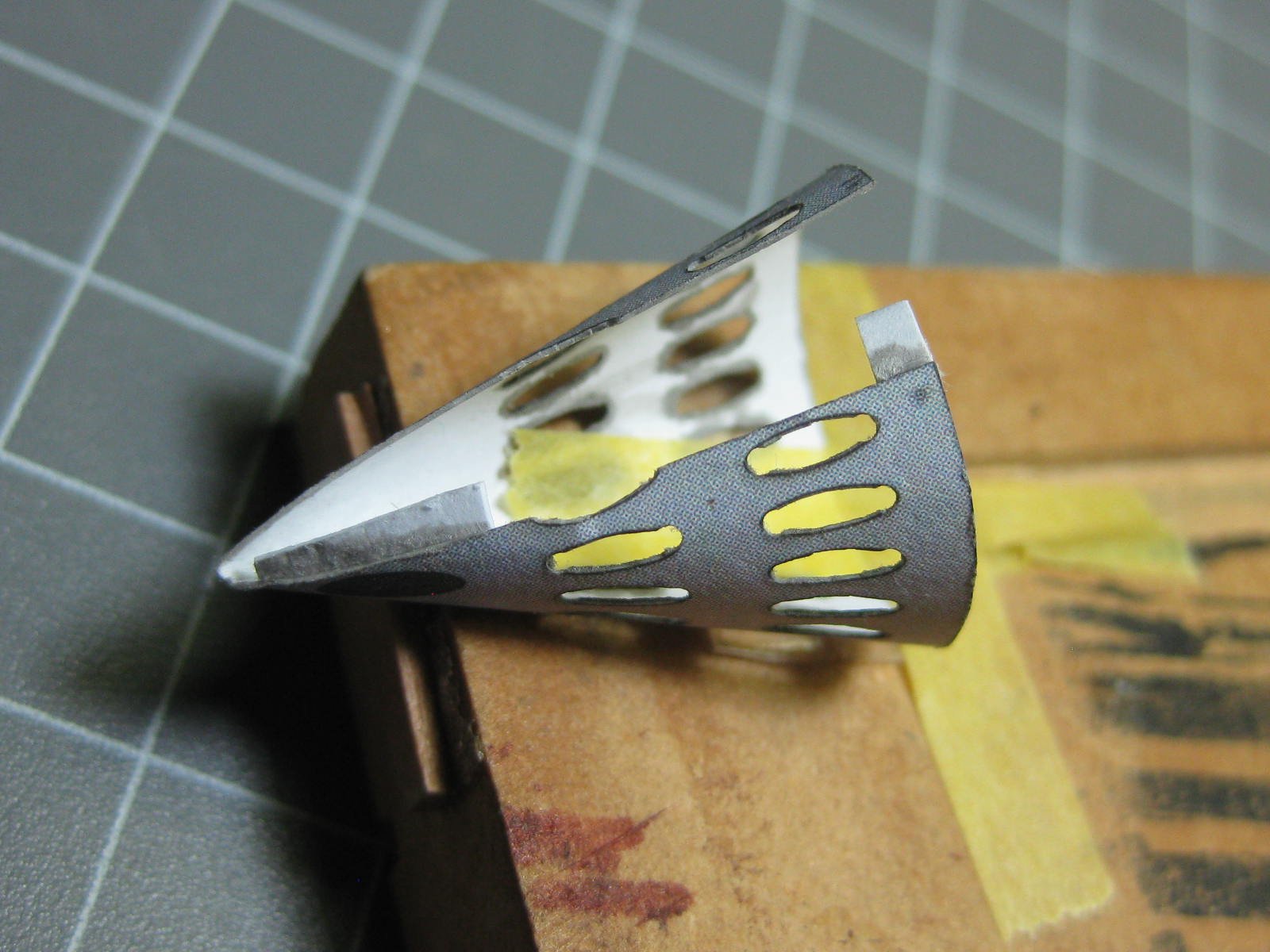
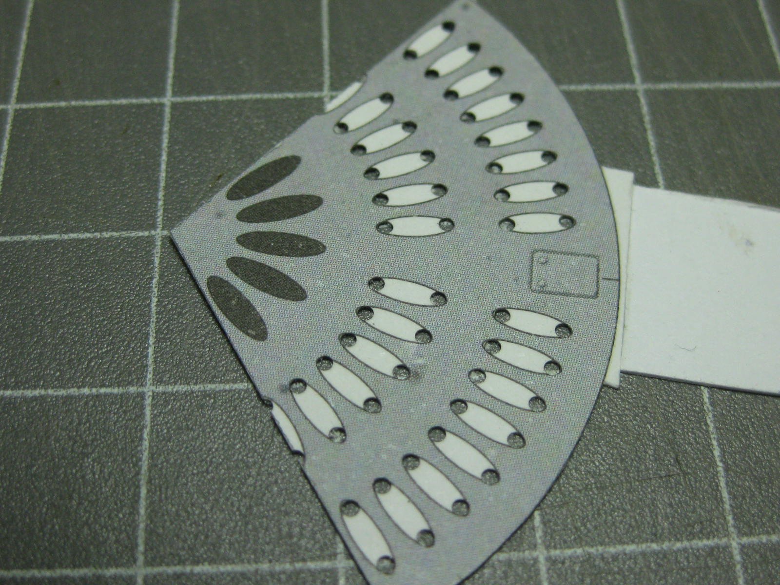
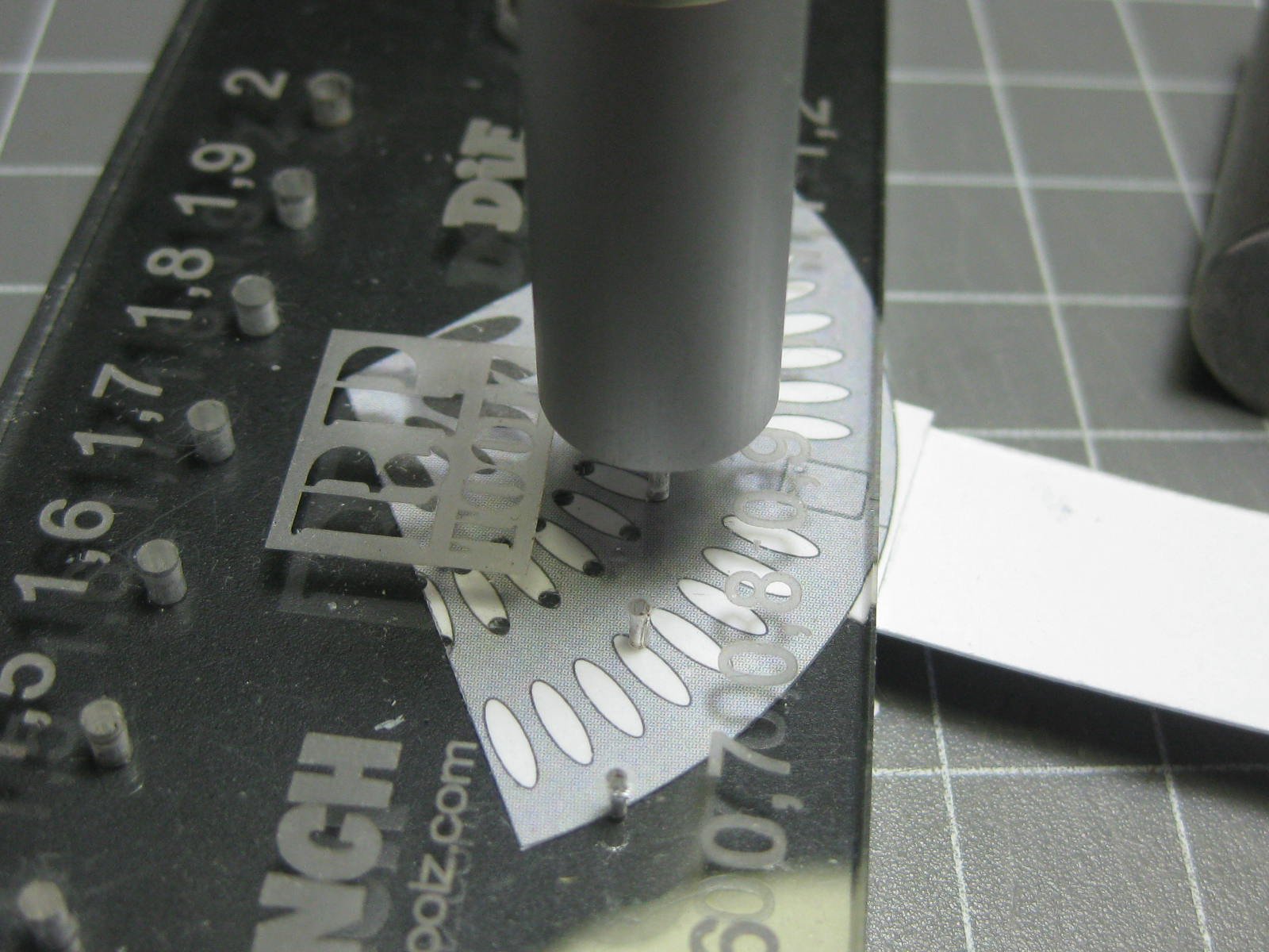
The two rocket launchers took me three days to make. The kit gives you the option of using 4 launchers, 4 bombs or a combination of the two. I've opted to do two of each. Hopefully the pics are fairly self-explanatory about the construction : There were a total of 58 1.0mm diameter angled tubes to make which fit inside the oval holes in the nose cones : I glued a toothpick to each cone for ease of handling : Aligning each internal tube was accomplished with the aid if a piece of 1mm wire : The tubes were not a perfect fit, but quite easy to trim down after the glue dried : A bit of touch-up acrylic paint was needed after the trimming : Finally, 5 more tubes were fitted to the end of each cone : Danny


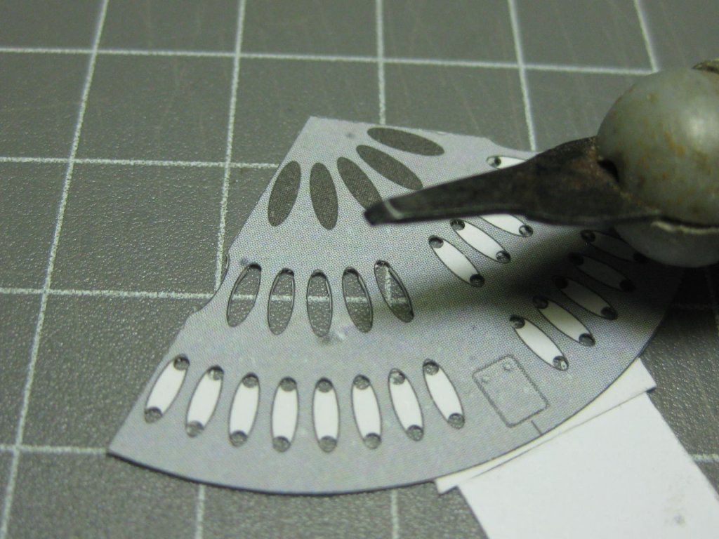


- 127 replies
-
- 16
-
-
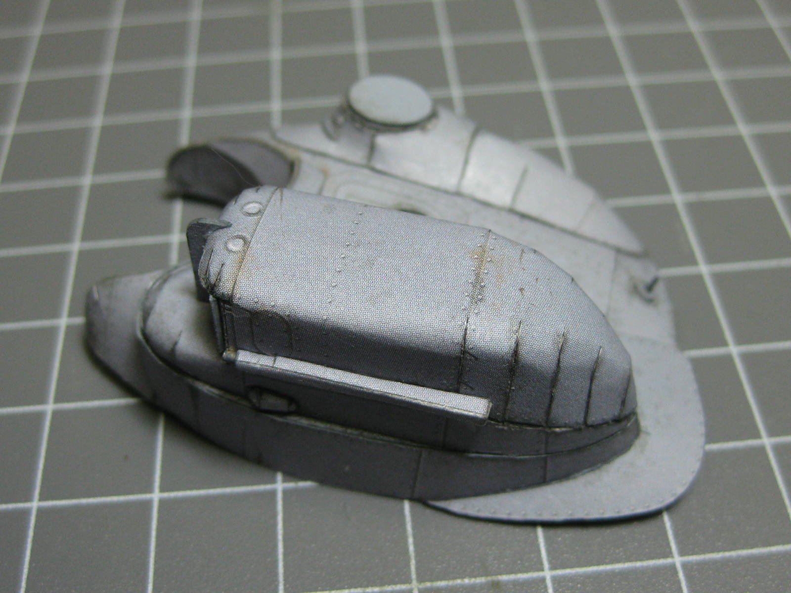
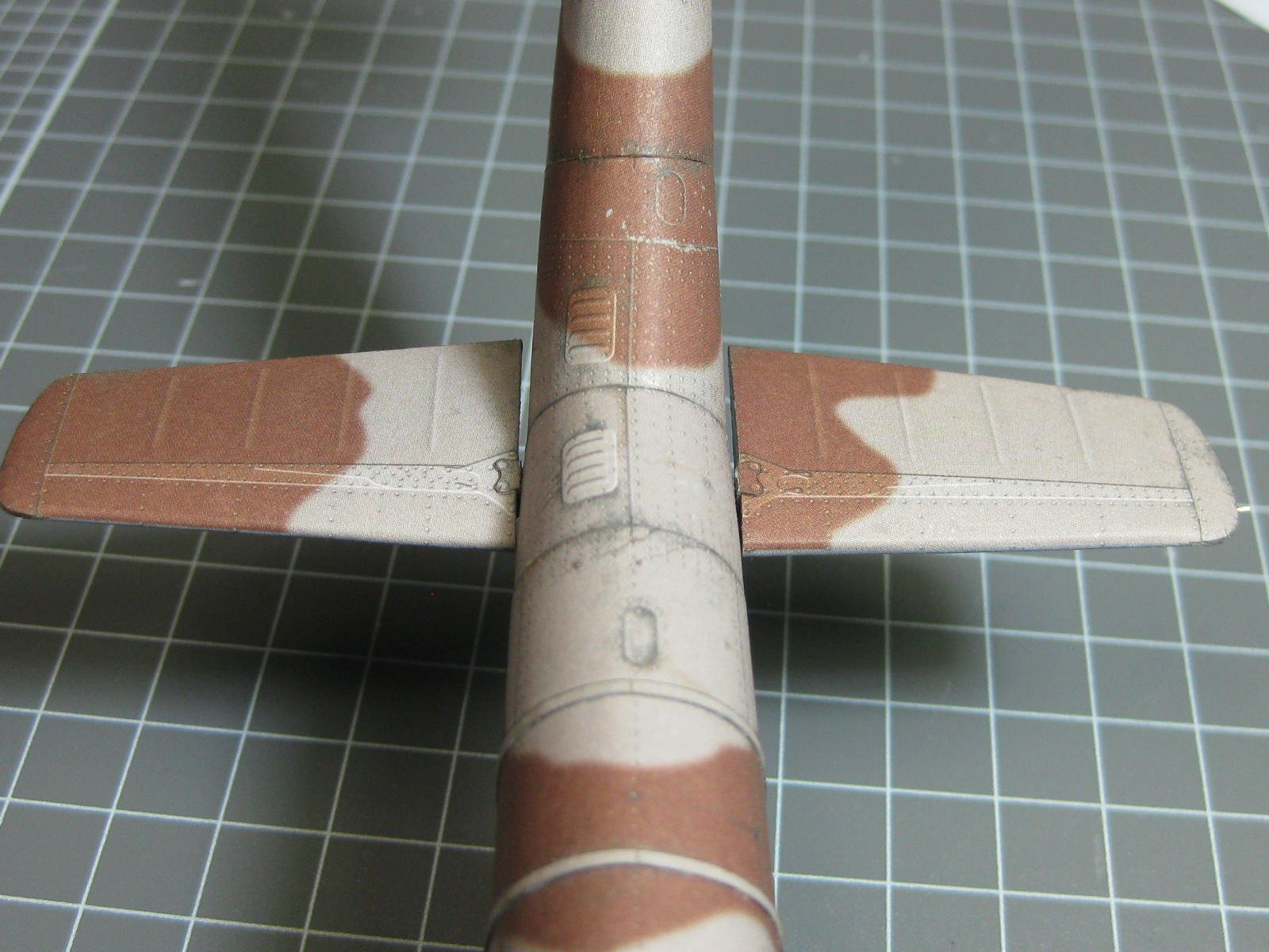
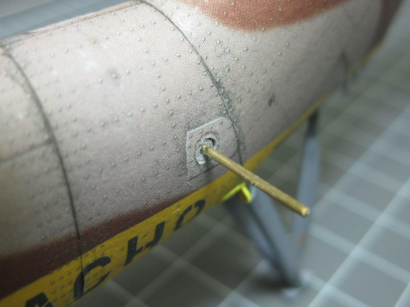
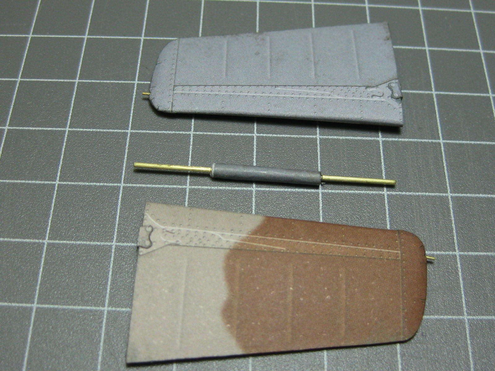
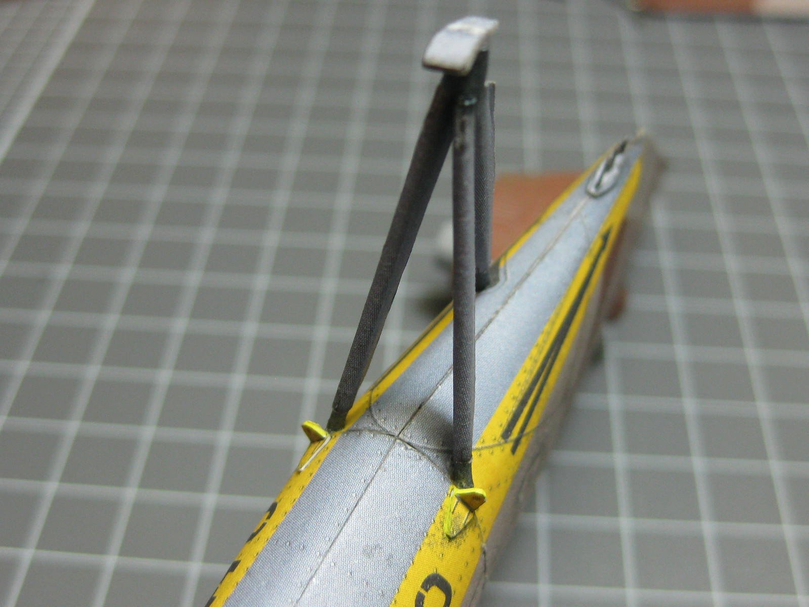
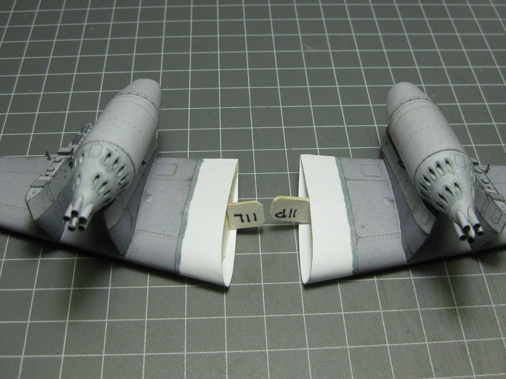
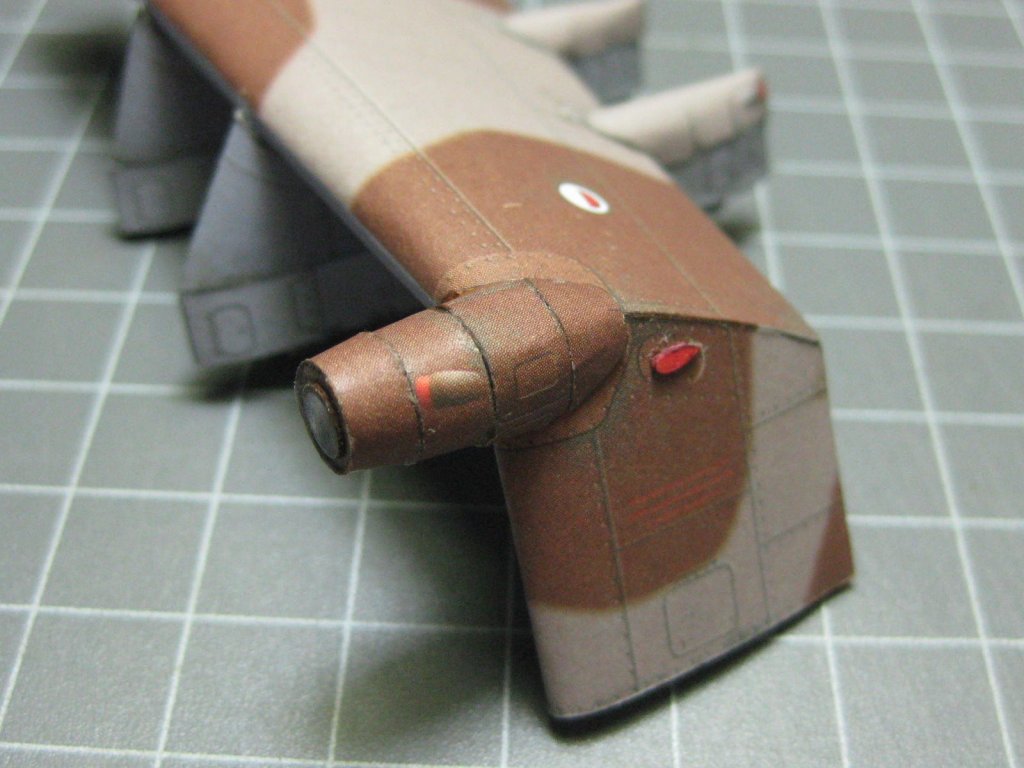
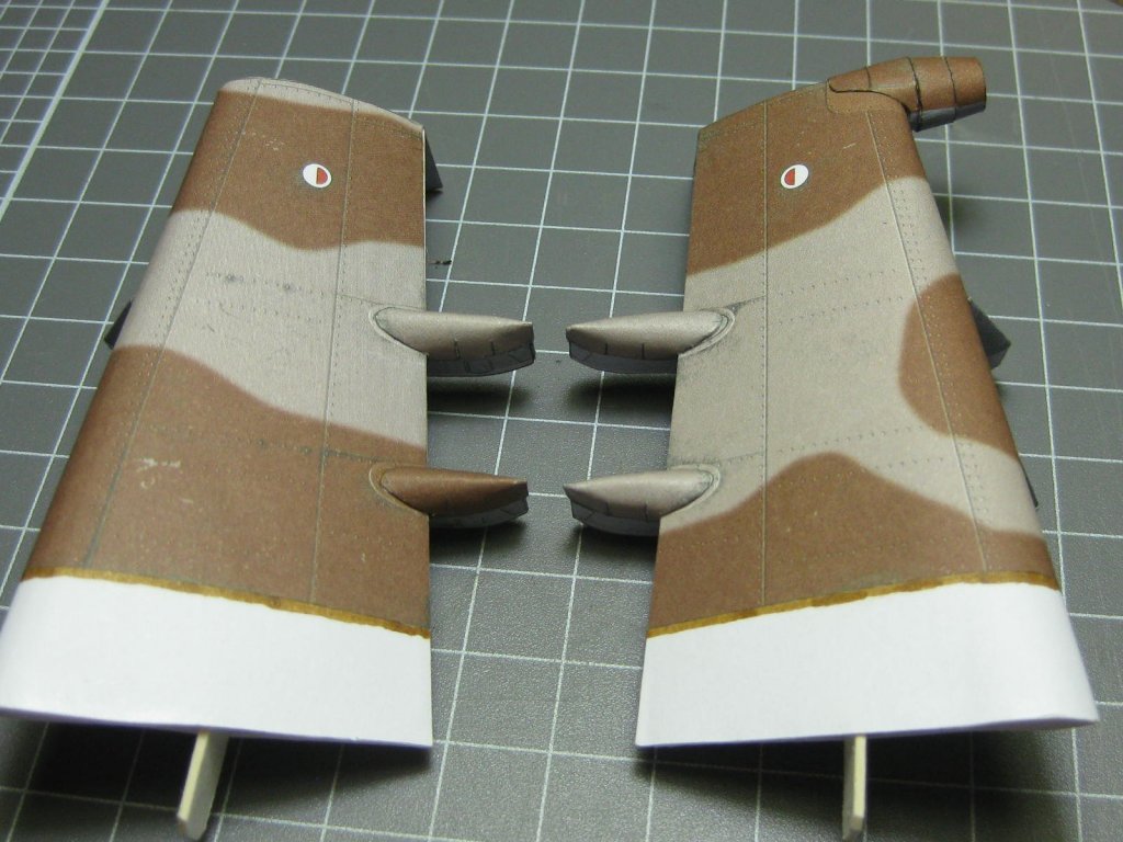
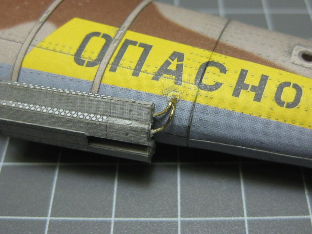
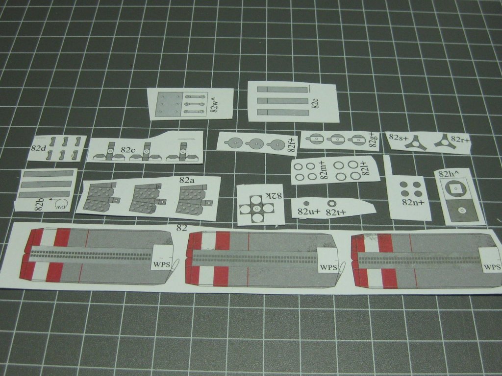
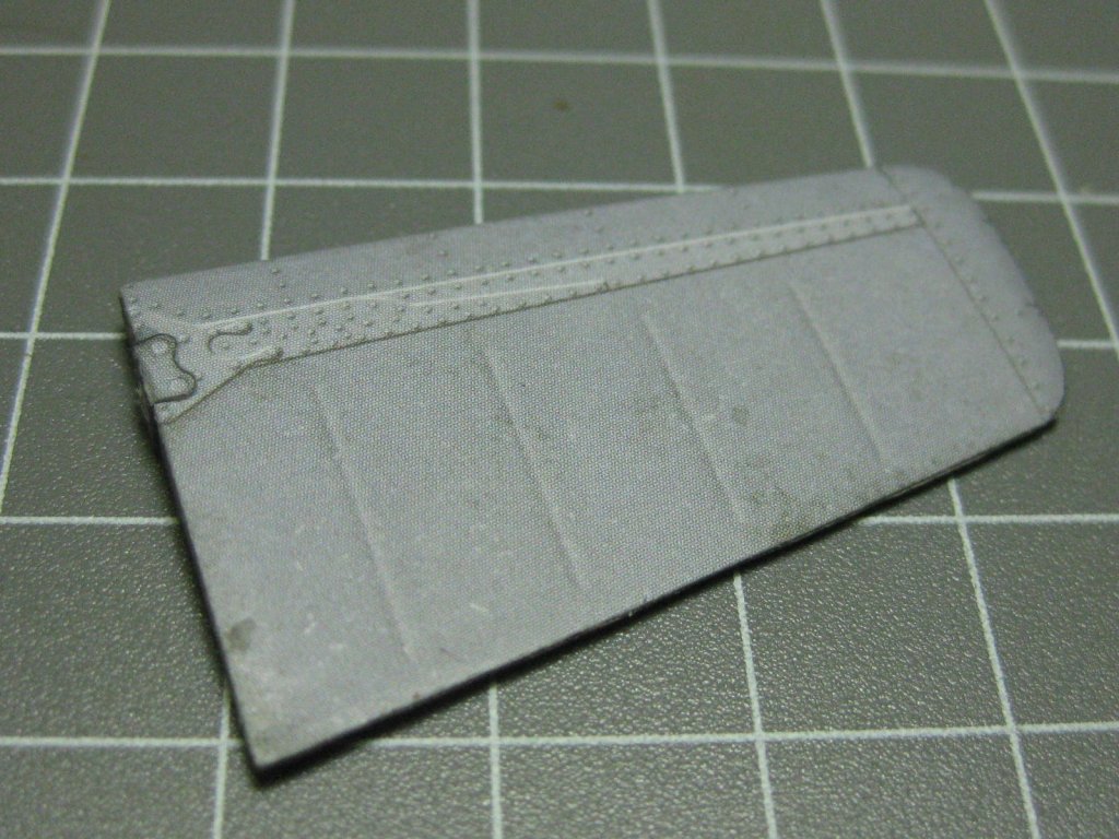
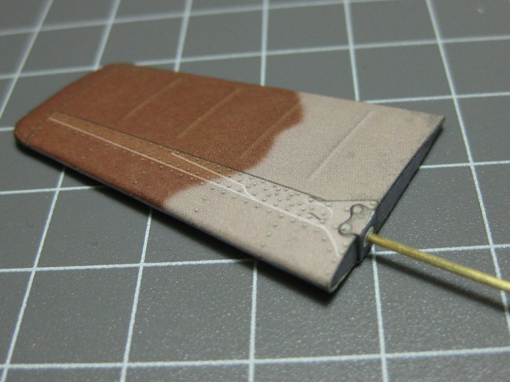
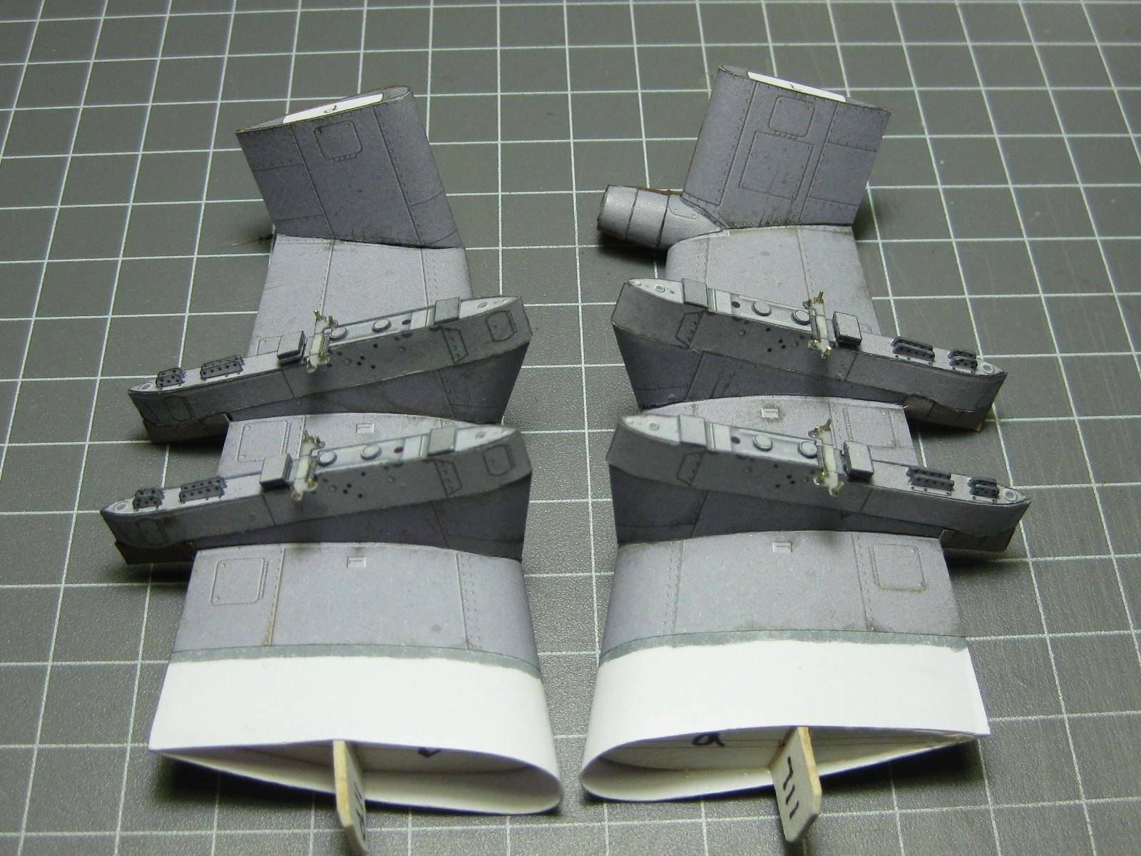
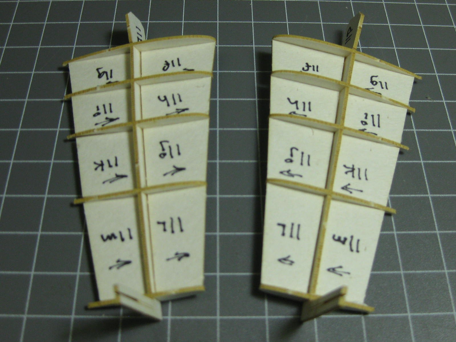
The "winglets", or Weapons System Platforms if you like, were a relatively easy step to construct. I had to glue the trailing edge of the wings in-situ after making up the frames this time, as the vertical pieces of the wings didn't allow me to fit the wings the "usual" way : The left wing has a pod attached : I made the rocket launcher/bomb pods as a demonstration of Card Model Building at the Port Macquarie Model show over the weekend, although I seemed to be spending most of the time explaining the construction of card models to interested spectators : Danny

- 127 replies
-
- 13
-
-
The "chain" placed on deck, it looks a bit flat, and not very inspiring. I don't have ideas how to spice this up, so it is left as provided by Scaldis: Jan, buy some small brass chain of the appropriate size, blacken (or paint) it, and glue it over the printed area : I suppose it depends on what you want from a model Jan. A Halinski kit would have had about 50 tiny parts for one capstan, all of them fitting perfectly . If you would rather make the simpler version ...... well, that's up to the builder. In my opinion Halinski is well worth the slightly higher price. Danny
.thumb.JPG.4bcb4bd46ae3df331646a4b9ead0ce29.JPG)
-
Hi all, Just some latest news about my model of HMS Hood - she took out "Best in Show" at the annual Port Macquarie Model Show. I took the half-finished model there last year, this year it was of course finished. I also took all the Card models I've built since then. A couple of pics of the show will follow tomorrow when I get home. Cheers, Danny
- 244 replies
-
- 19
-
-
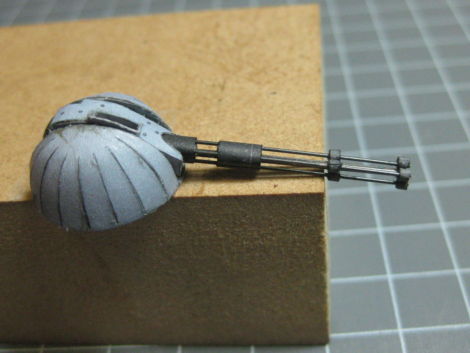
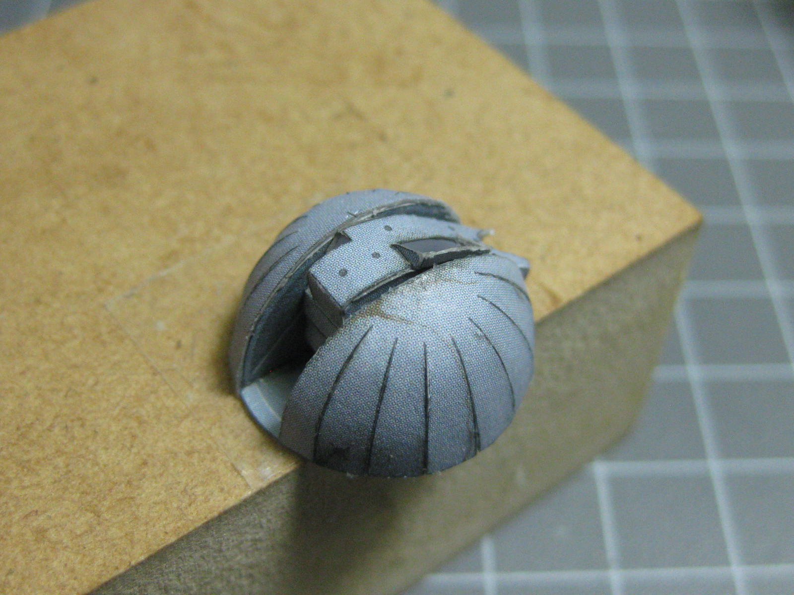
The four-barrel "Gatling" type gun and it's swivelling mounting. This is another piece that will be fitted later in the build : Danny


- 127 replies
-
- 15
-
-
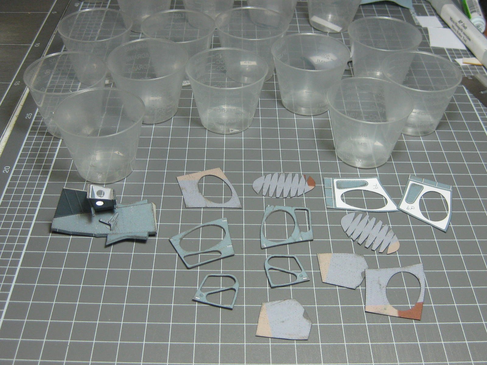
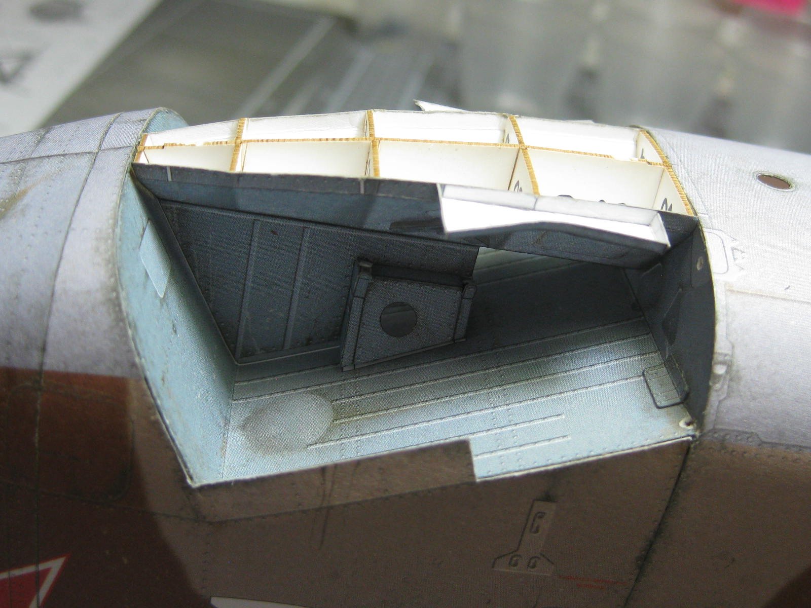
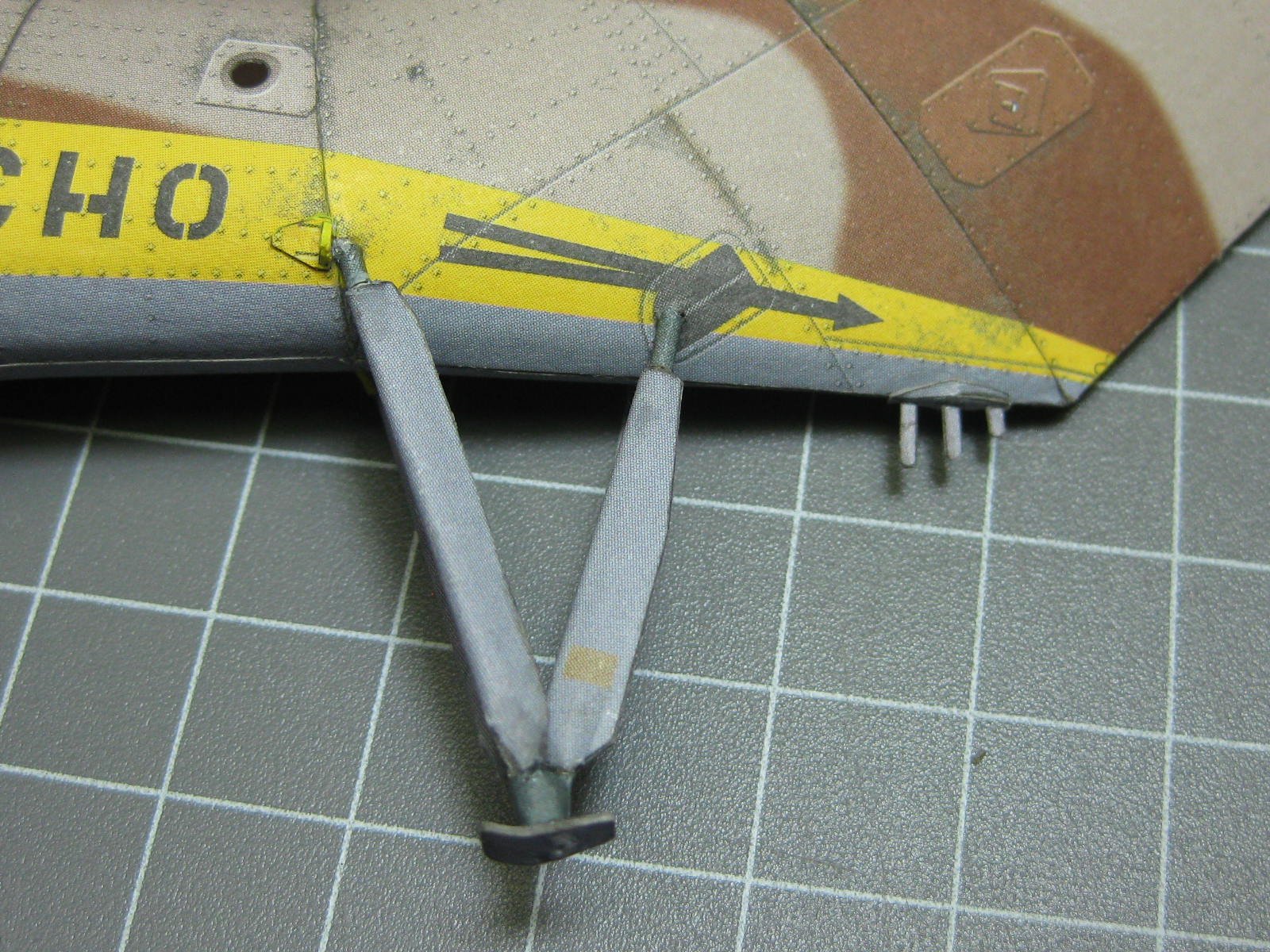
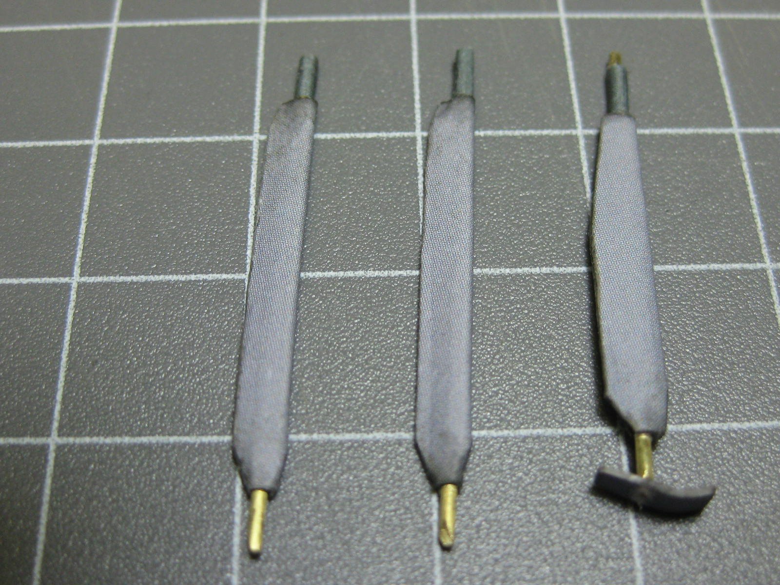
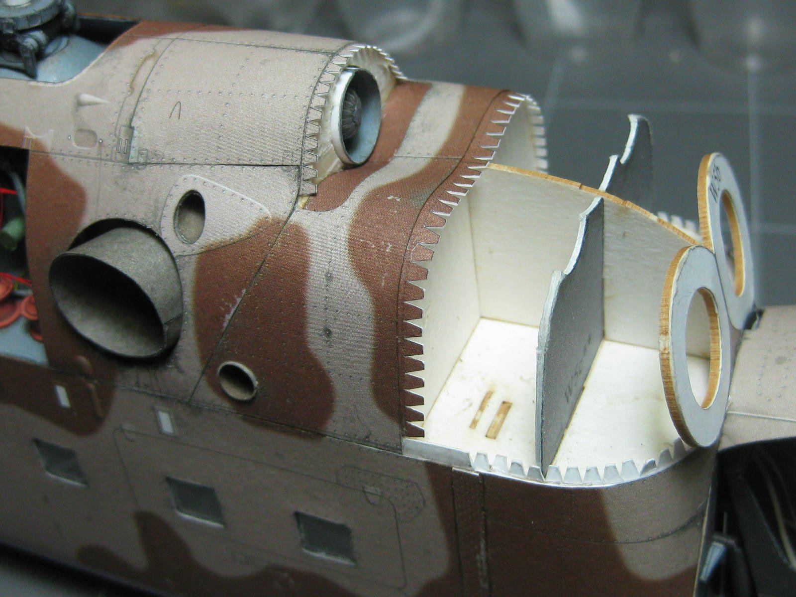
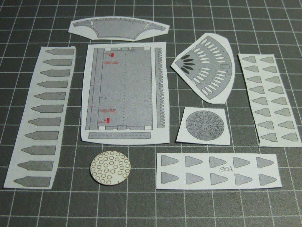
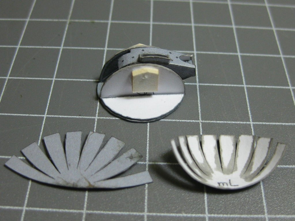
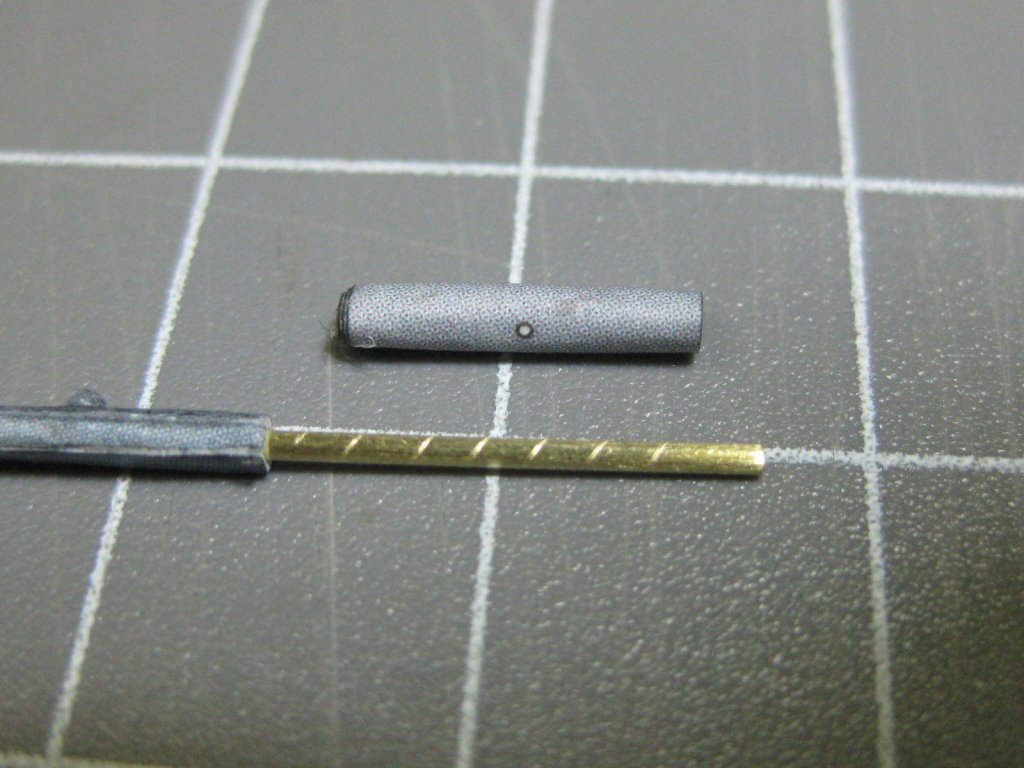
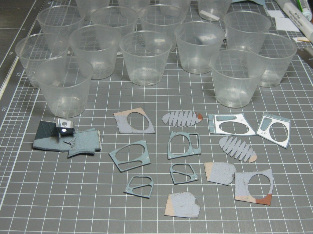
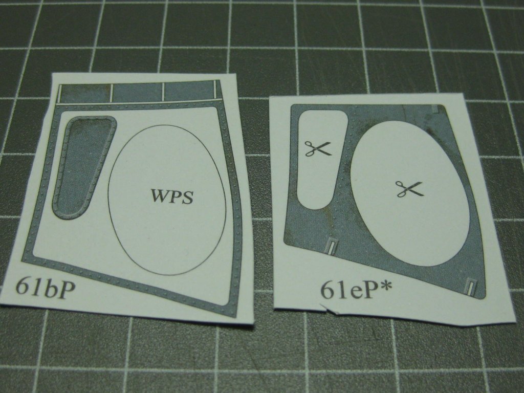
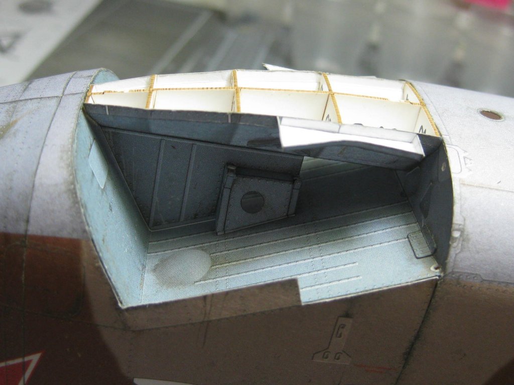
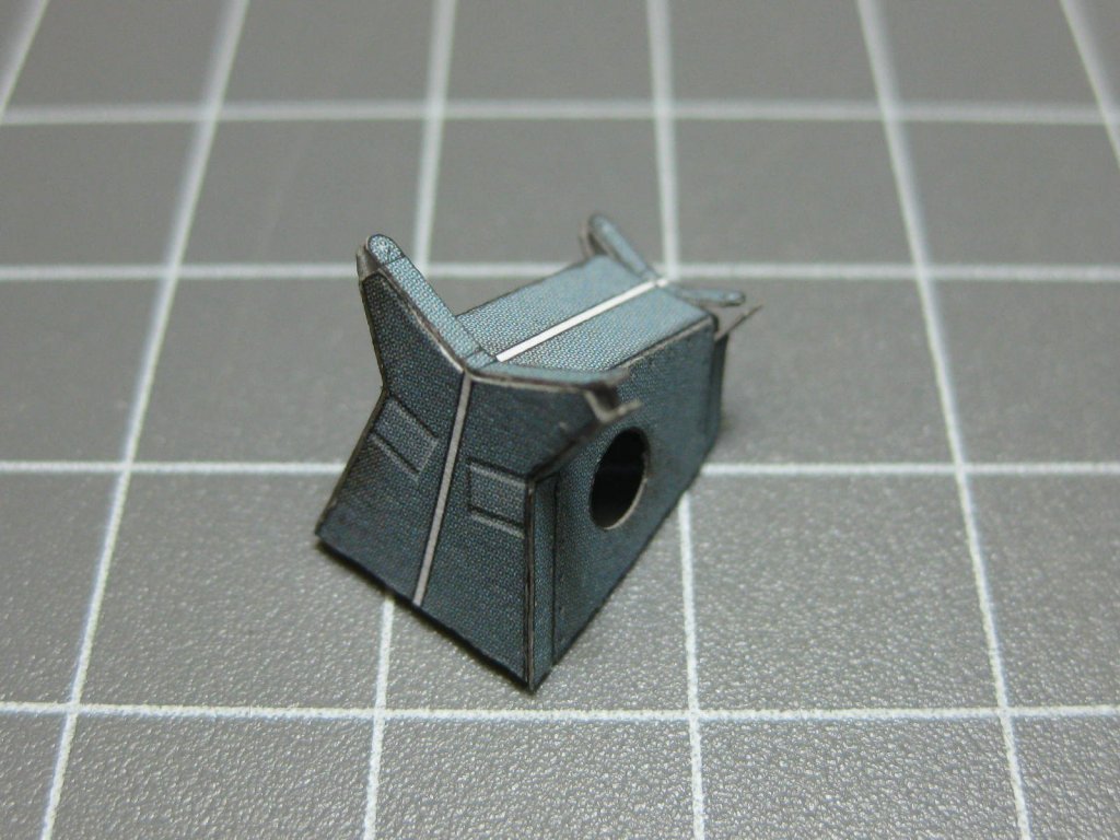
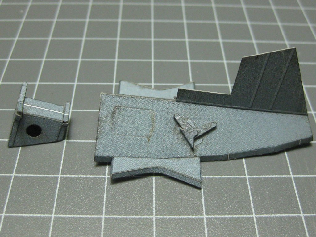
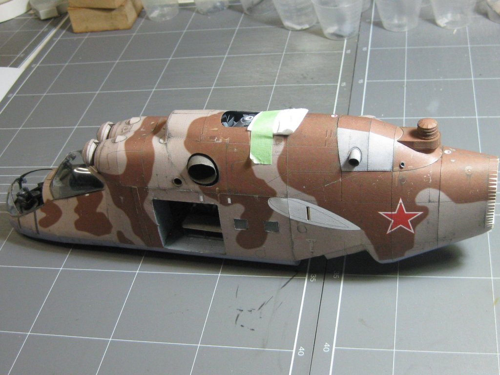
This is the main landing gear bay. I'm going to install all the parts for this and prepare it for the landing gear, but I won't fit the gear until the winglets have been fitted : Two of the four landing gear doors : The medicine cups hold the myriad of different parts for the landing gear struts, among a few other items : One of the landing gear struts. Note the spiral groove cut into the wire with an Xacto knife to assist in glue adhesion : Danny


- 127 replies
-
- 14
-
-
That's because you have viewed your build log since the last time you entered a post. It's an automatic thing, it'll go to bold again the next time you post. You'll find the same thing happens to any other build log you open. BTW - you can't Format a Title (font, colour, bold etc). Danny
-
QUICK-FIND INDEXES to BUILD LOGS FOR KITS
Dan Vadas replied to Dan Vadas's topic in - Index of all kits by brand and subject
It's not you Mike, it was all ME (and not for the first time either). I uploaded the wrong files this morning when I updated the Indexes. Sorry about that . Thanks for the "heads up". All fixed now. Danny -
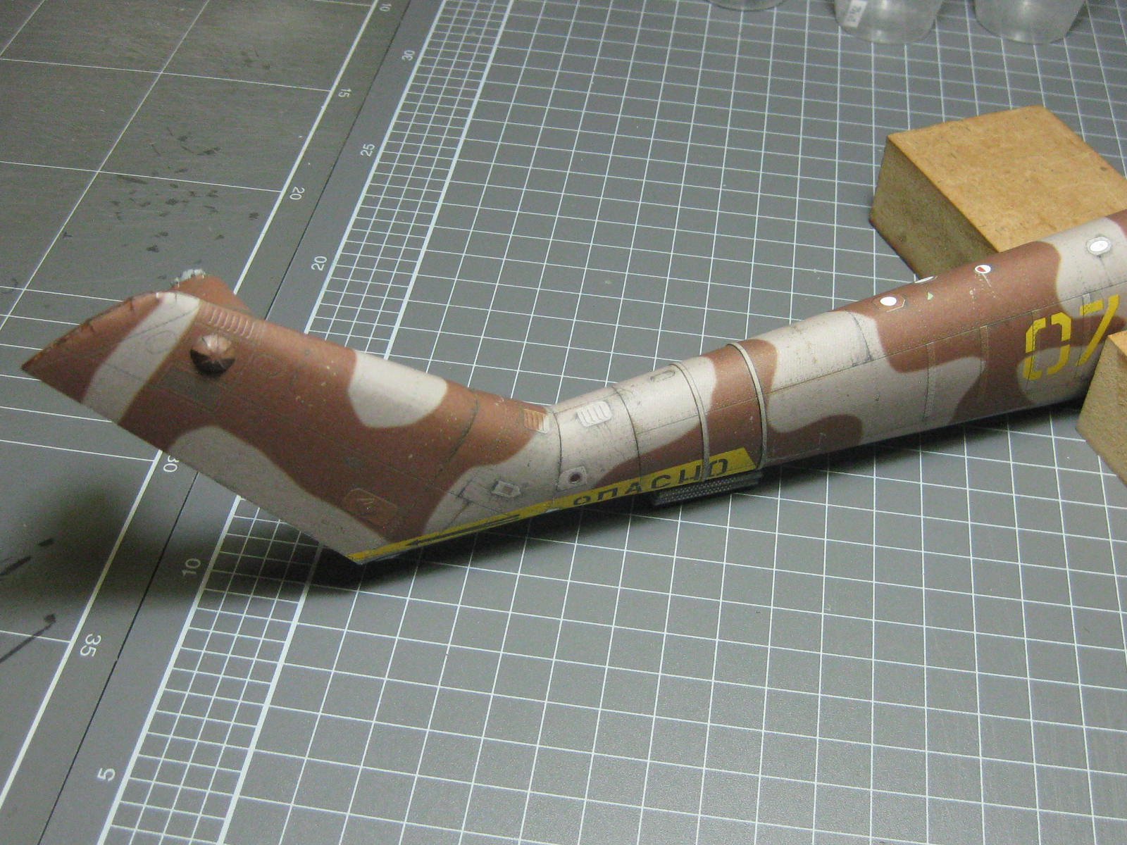
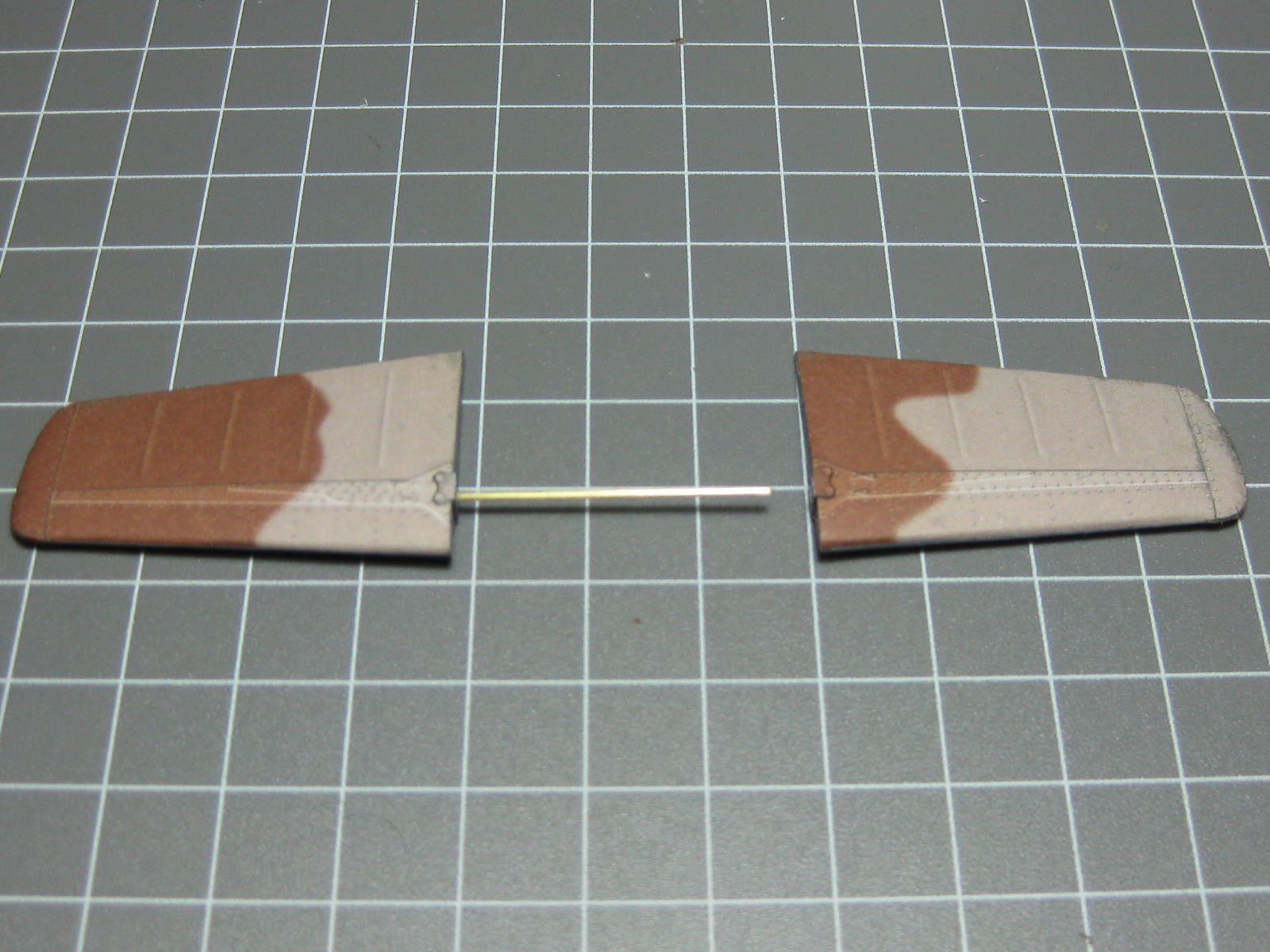
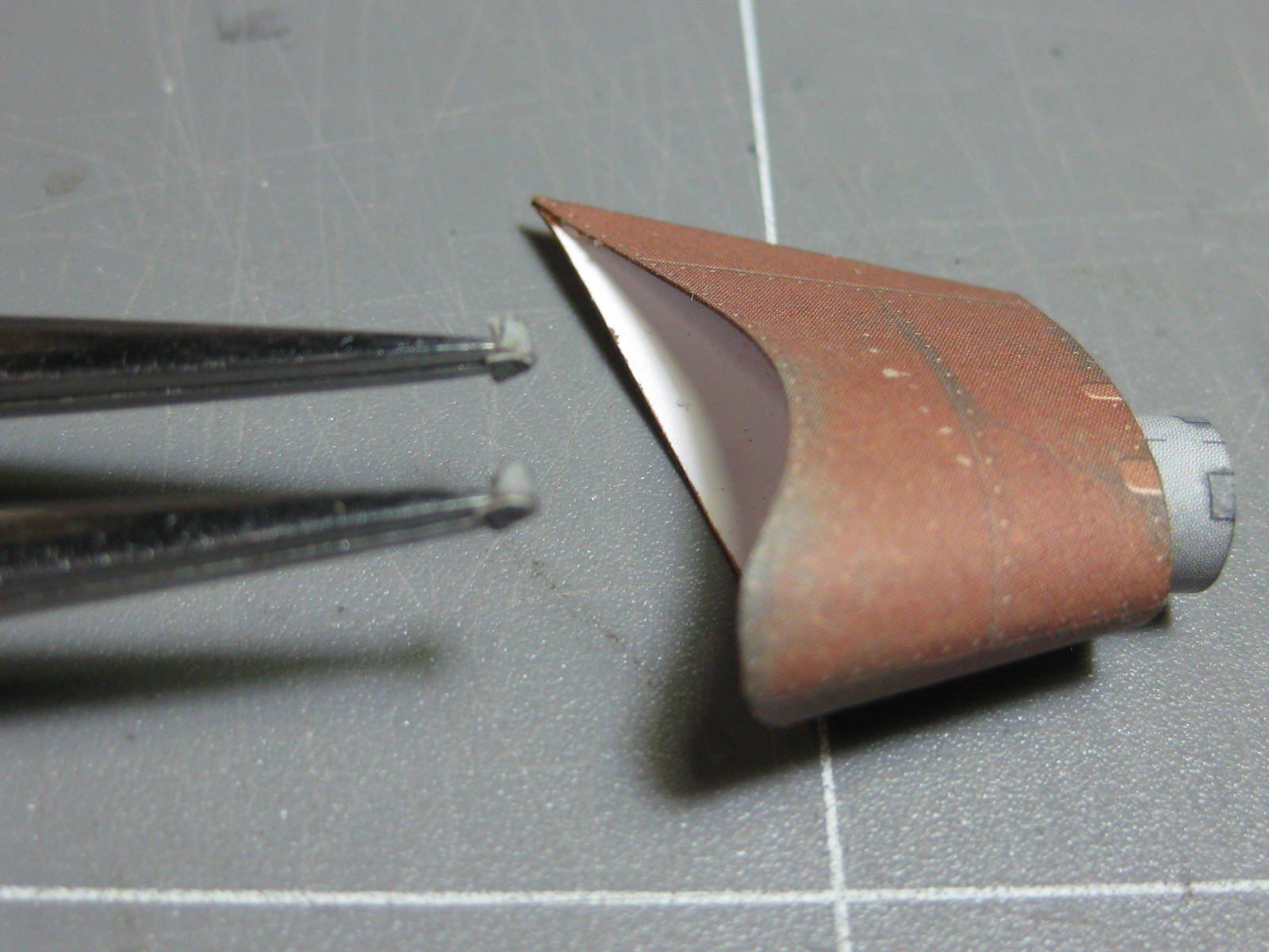
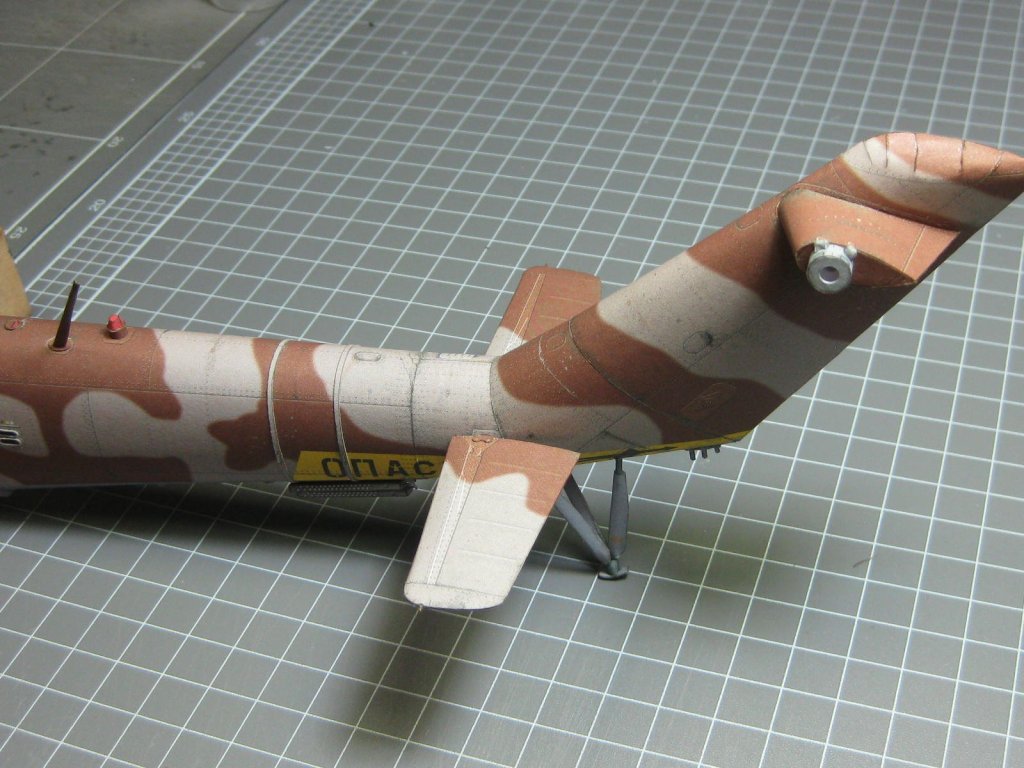
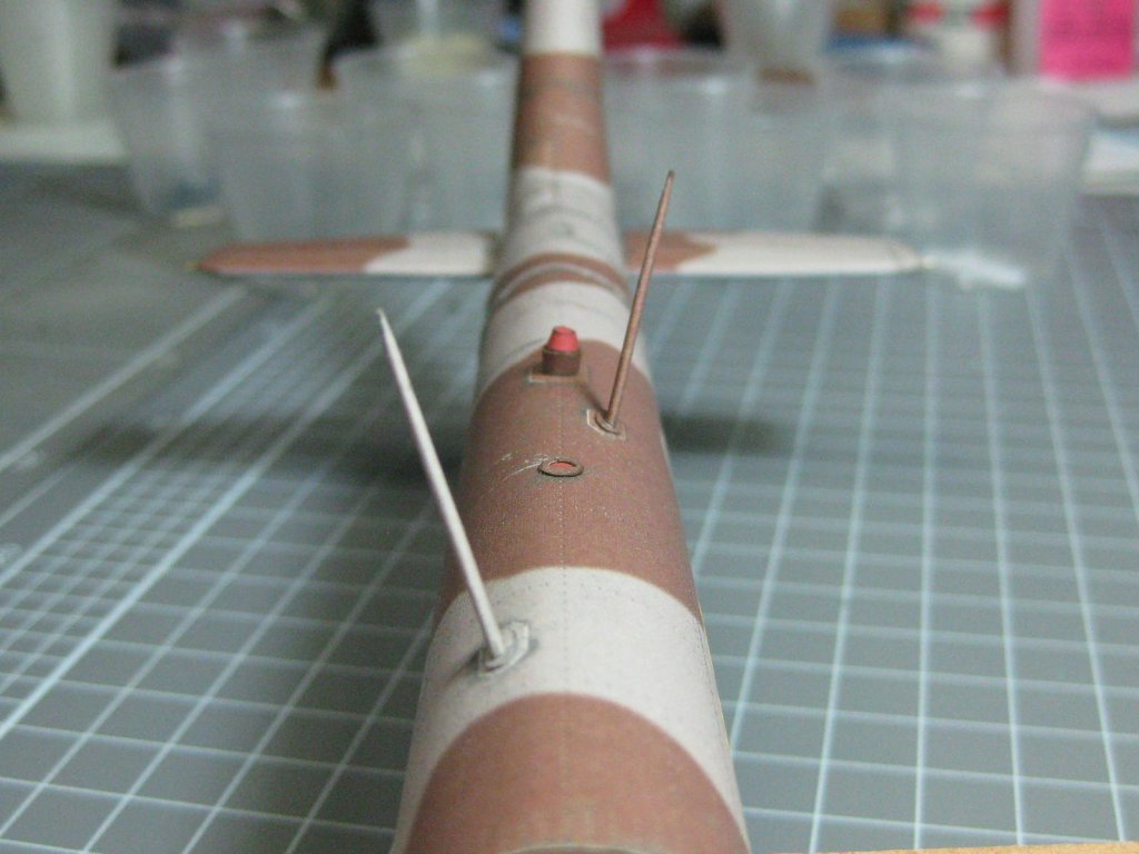
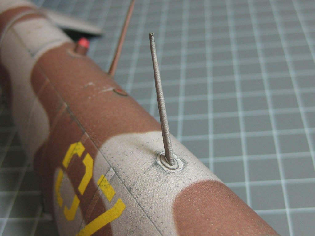
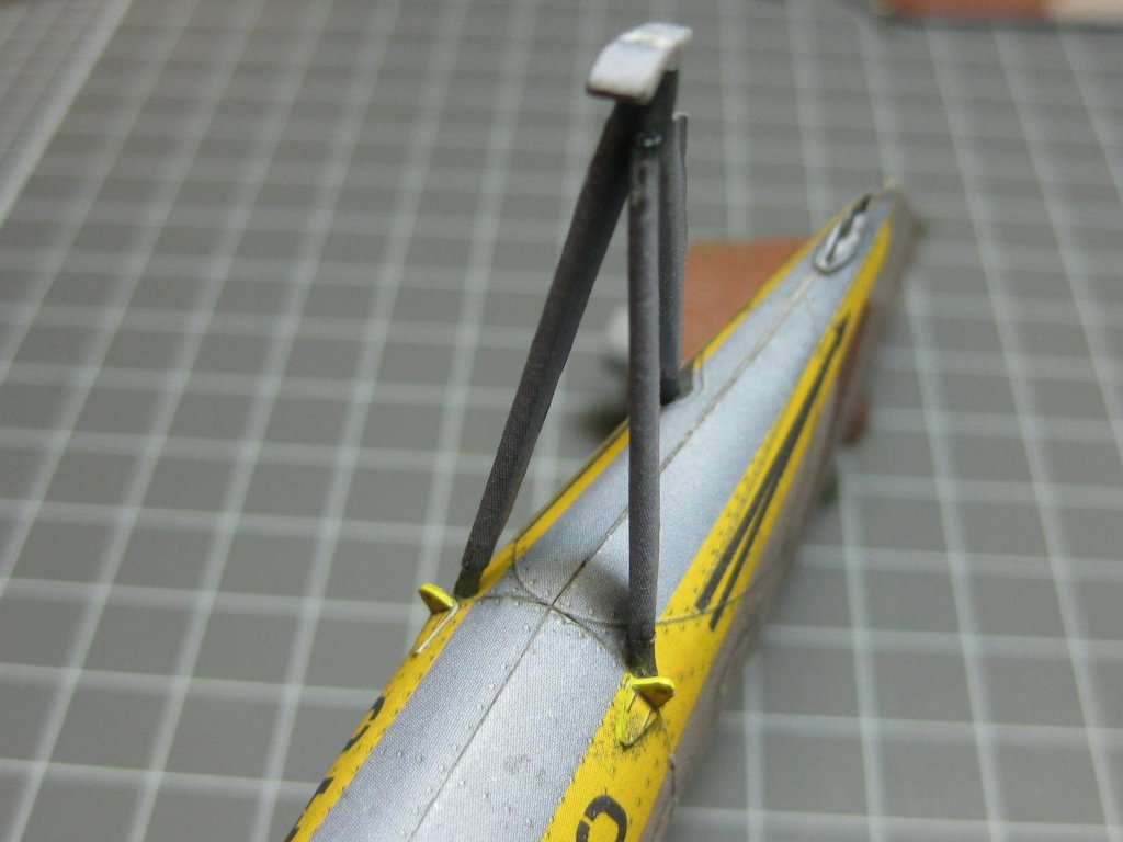
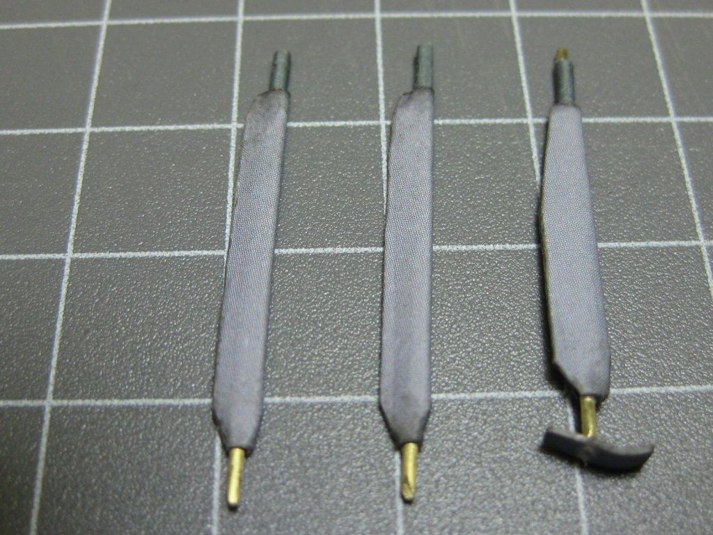
The elevator support wire needed a piece of paper wrapped around it : Last of the pieces for the tail section. Yes, they are meant to be mounted at an angle : Danny


- 127 replies
-
- 14
-
-
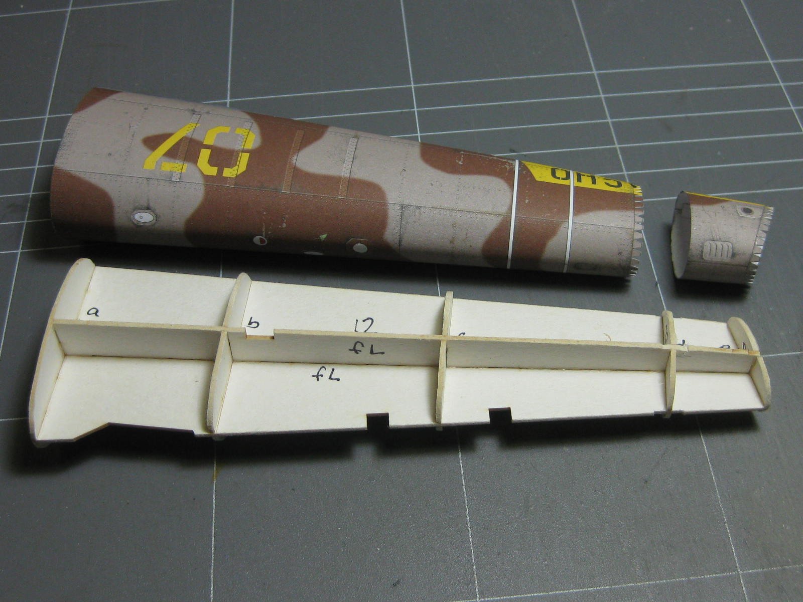
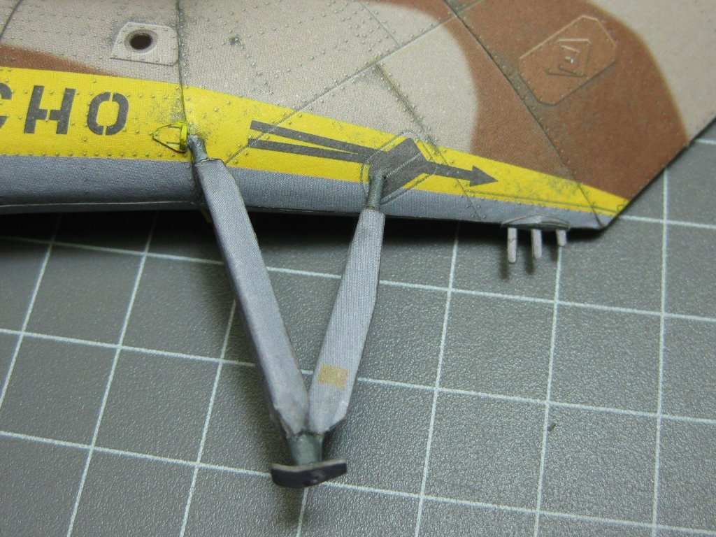
The tail sections have been fitted together : This looks like some kind of cooler, oil perhaps ? Last of the bigger pieces for the tail section : The struts of the rear support : Danny


-
How many known HMS Victory kits are there?
Dan Vadas replied to Vane's topic in Wood ship model kits
Also Corel 1:98. Danny -
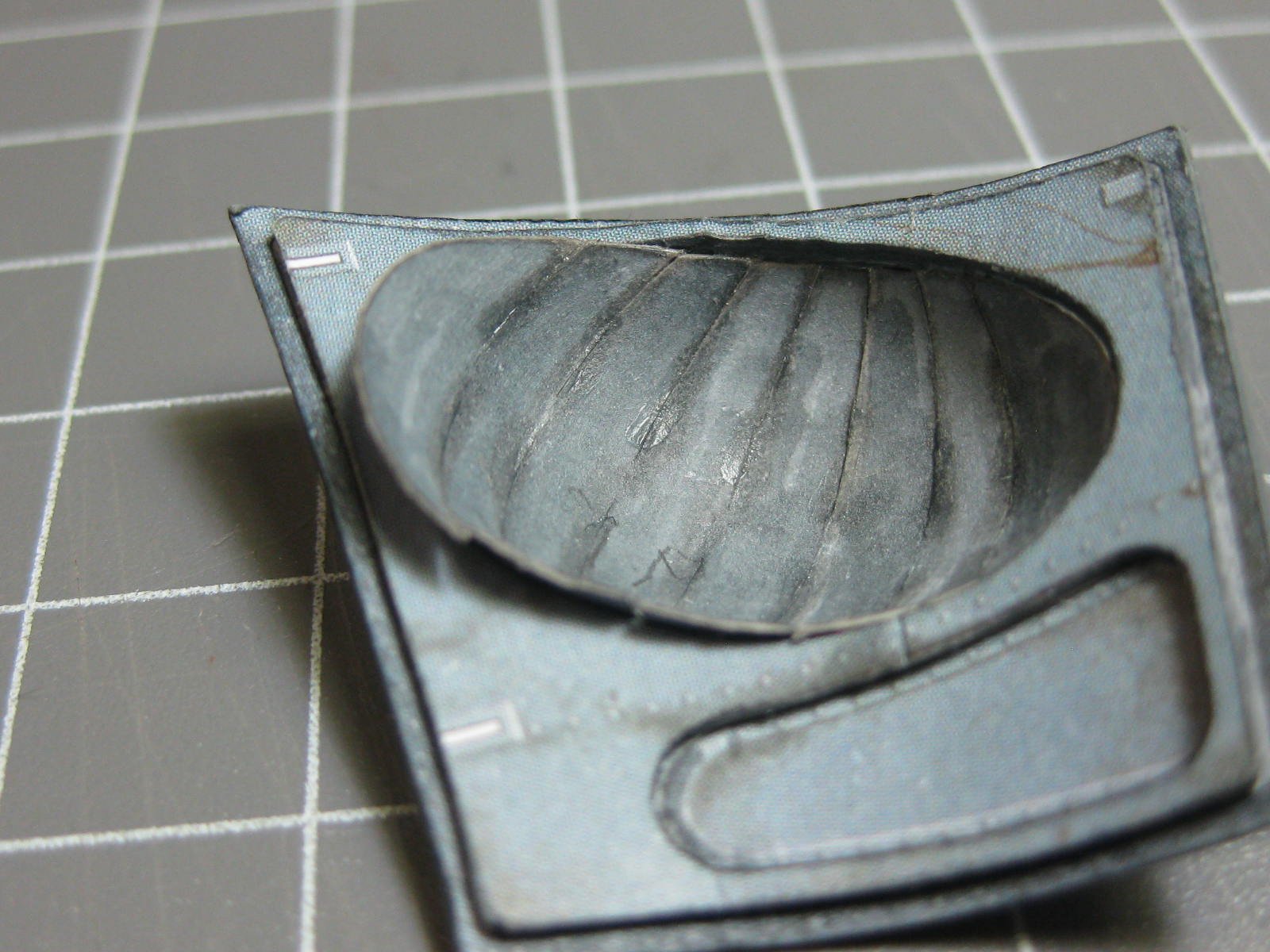
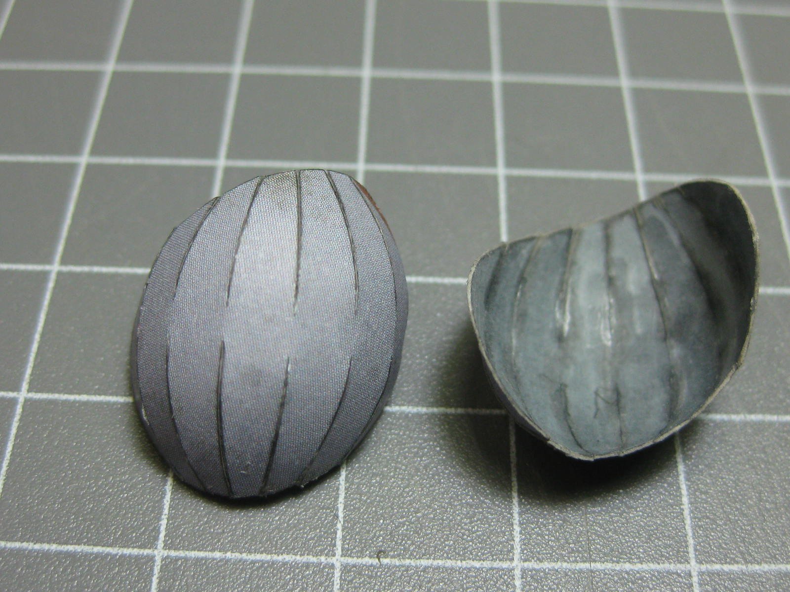
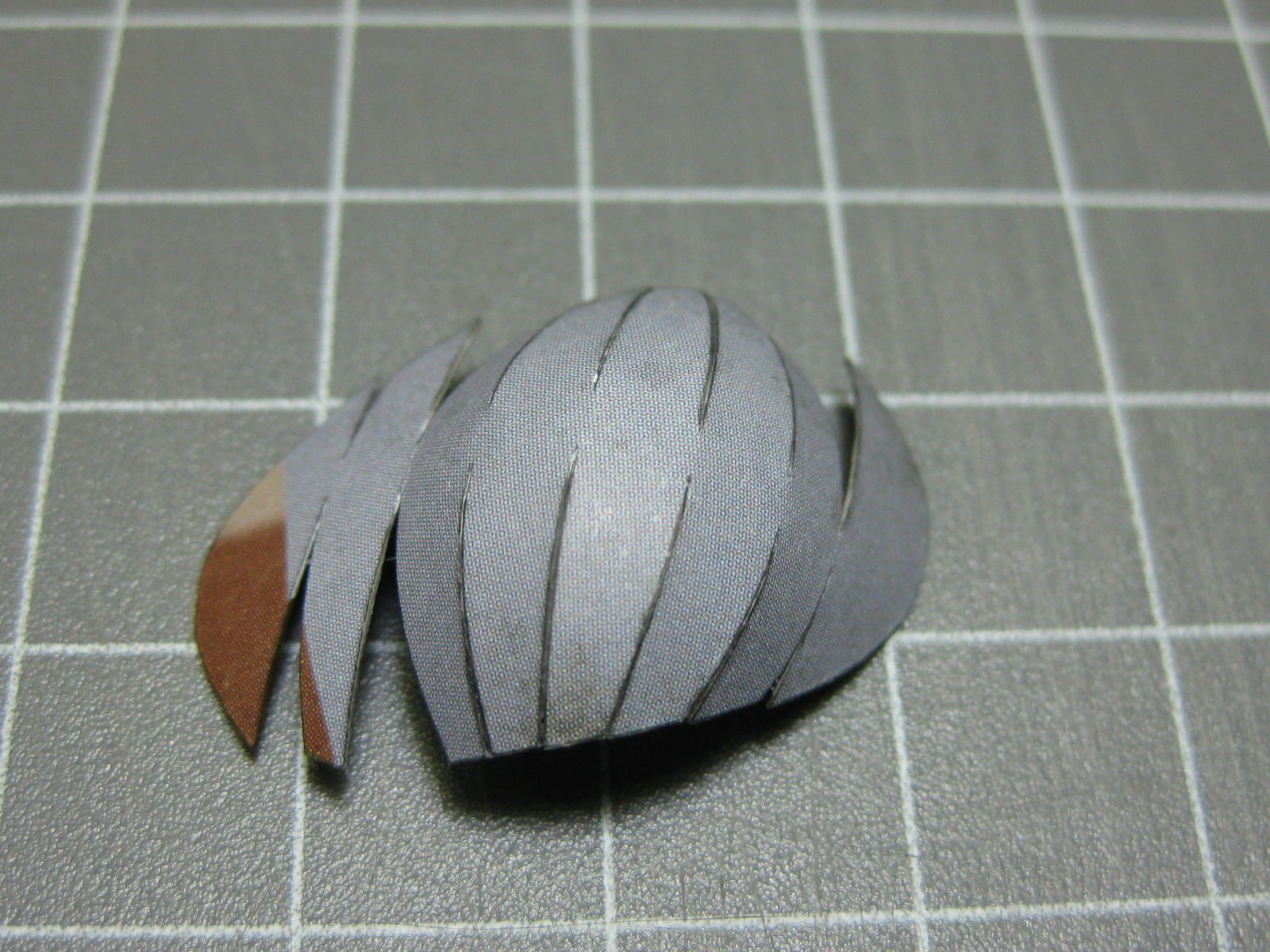
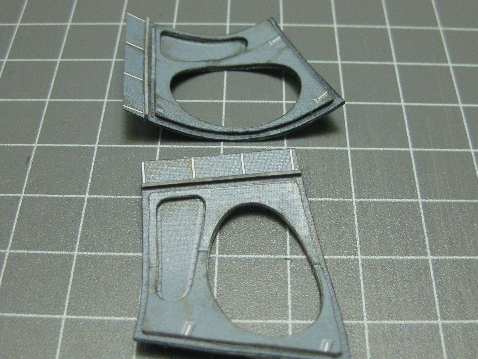
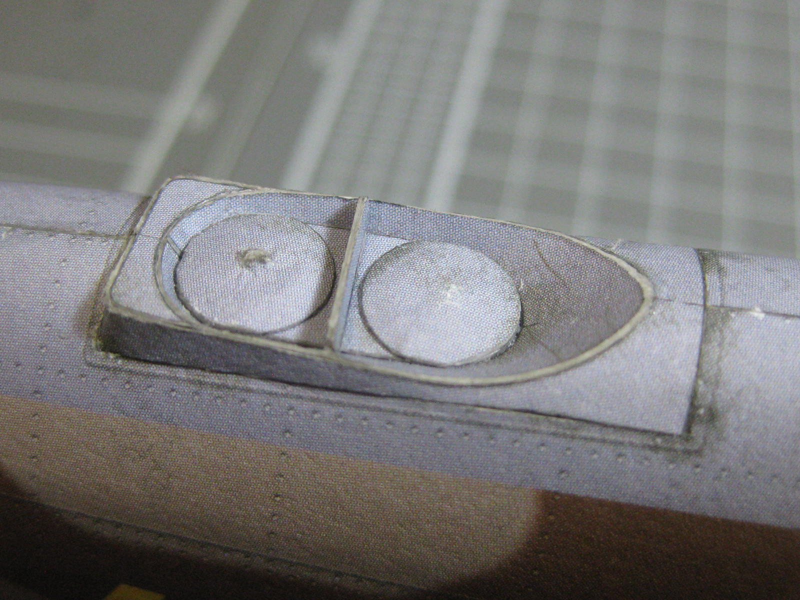
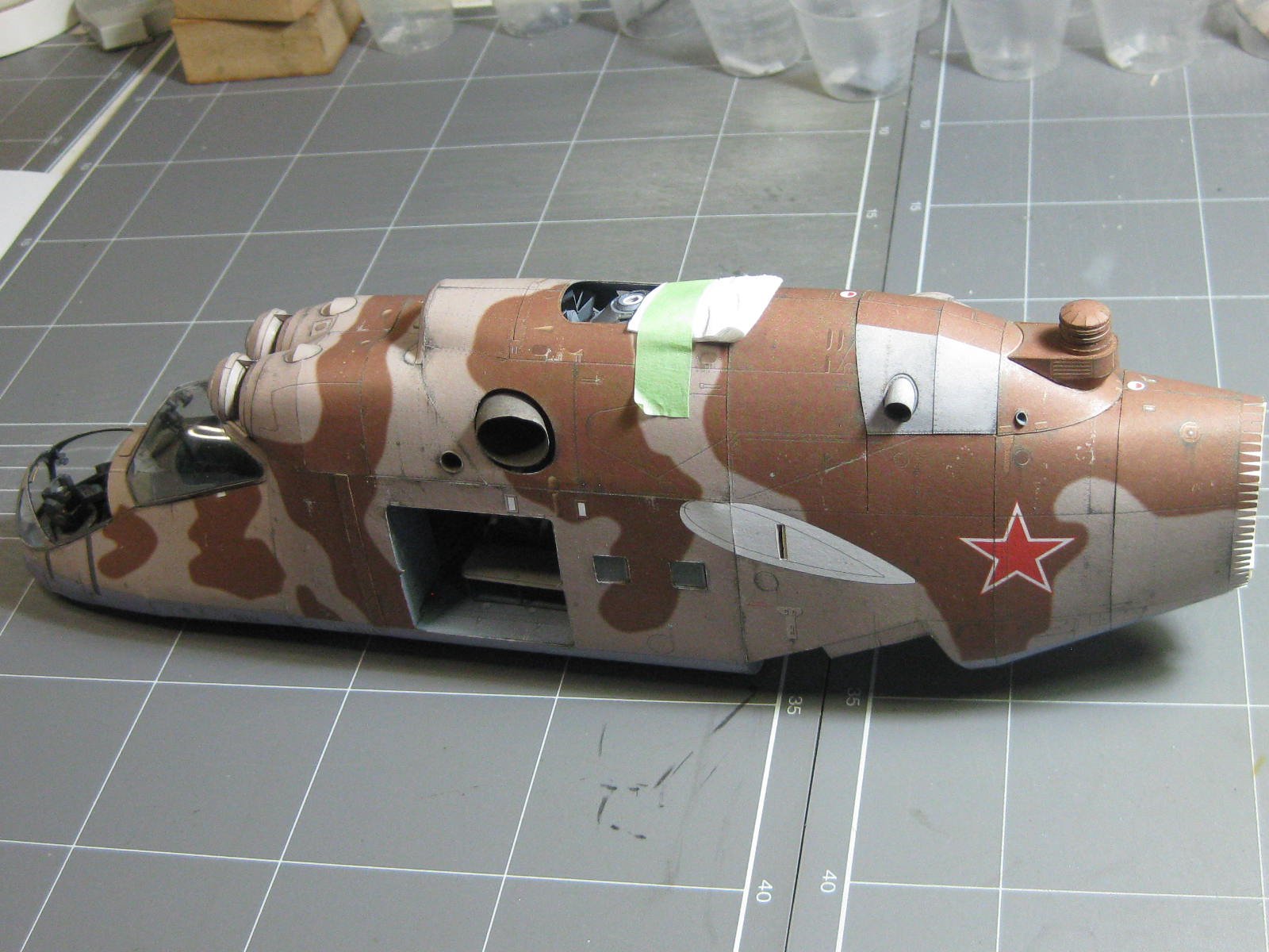
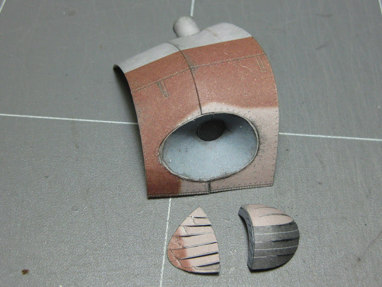
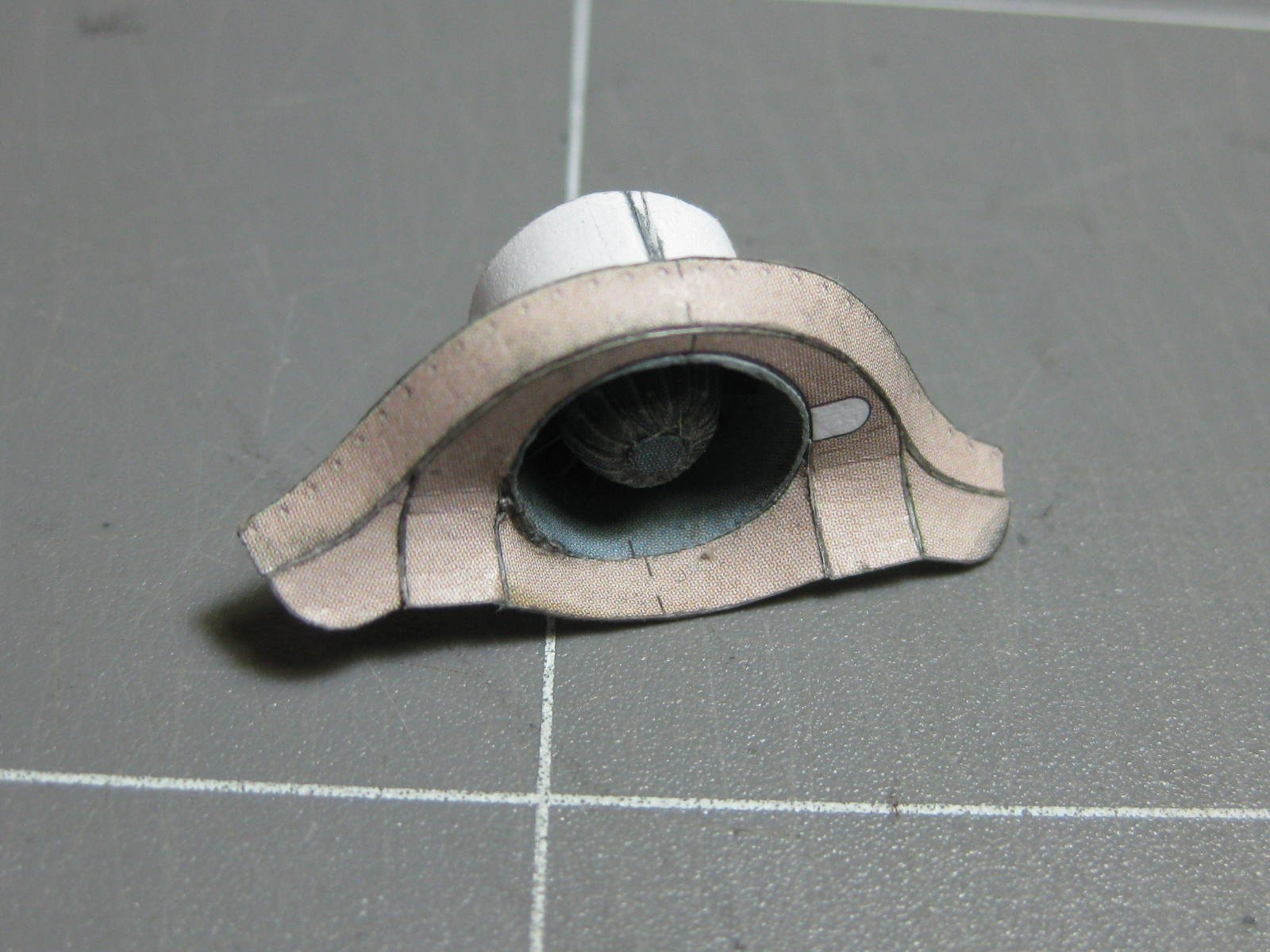
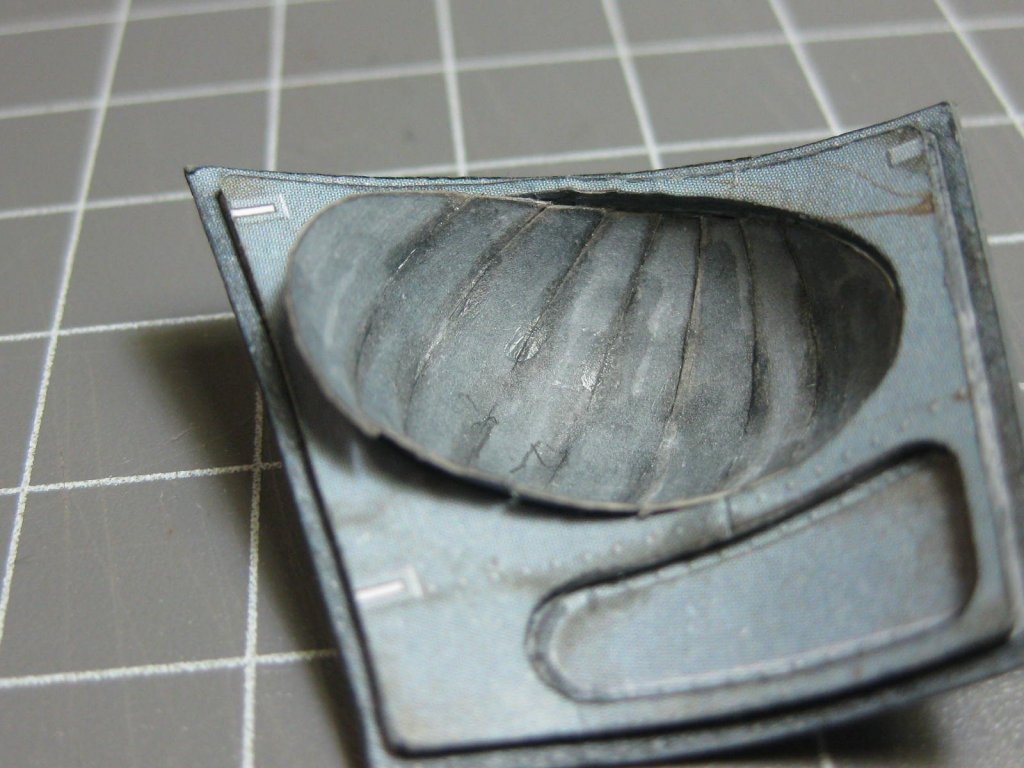
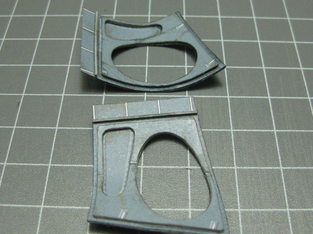
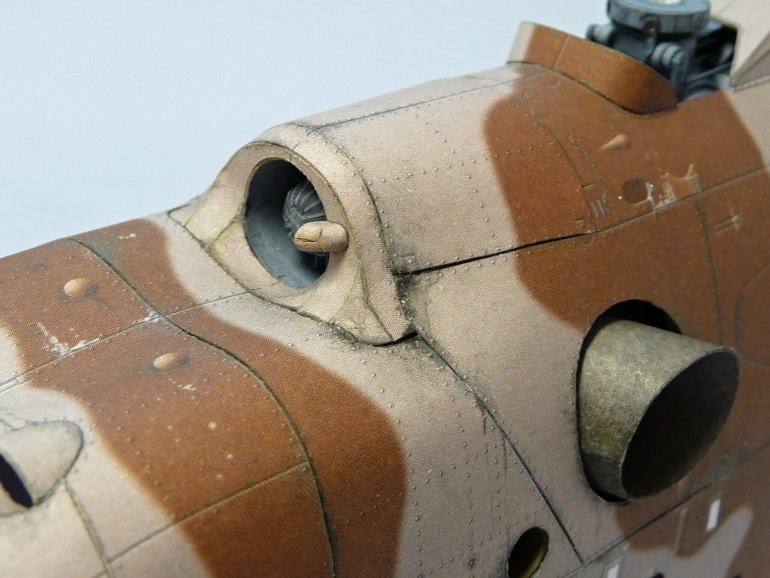
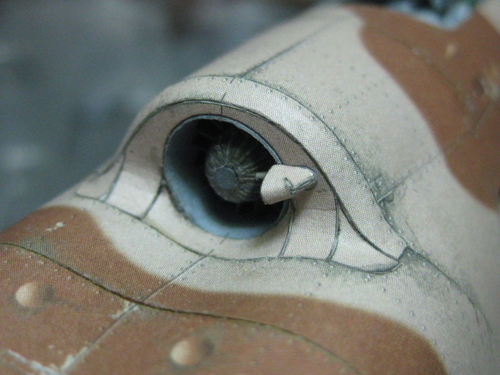
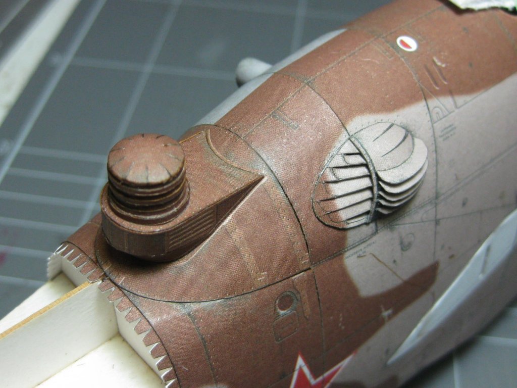
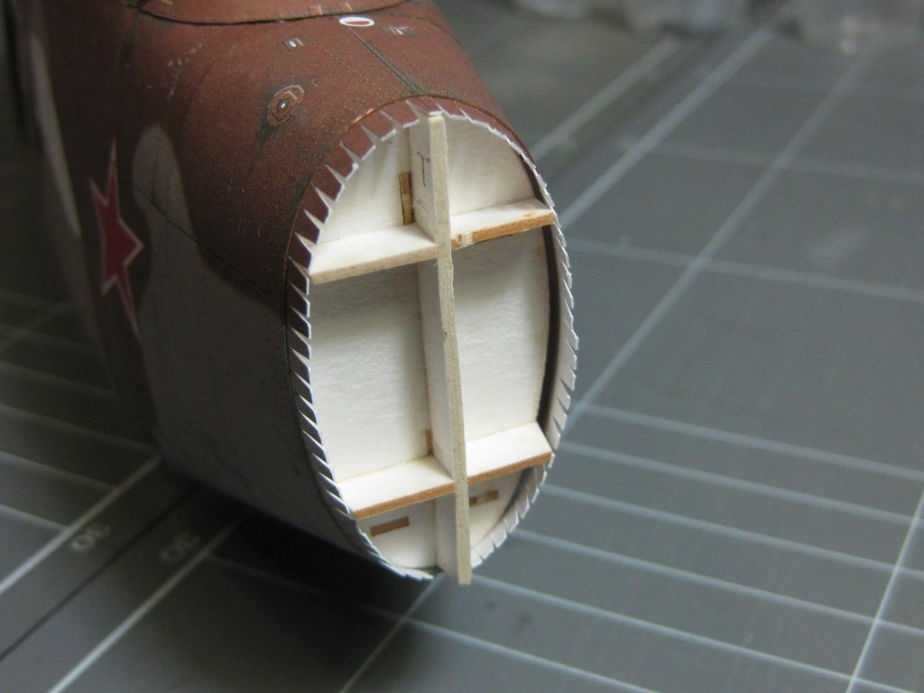
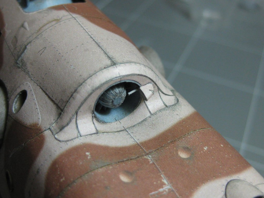
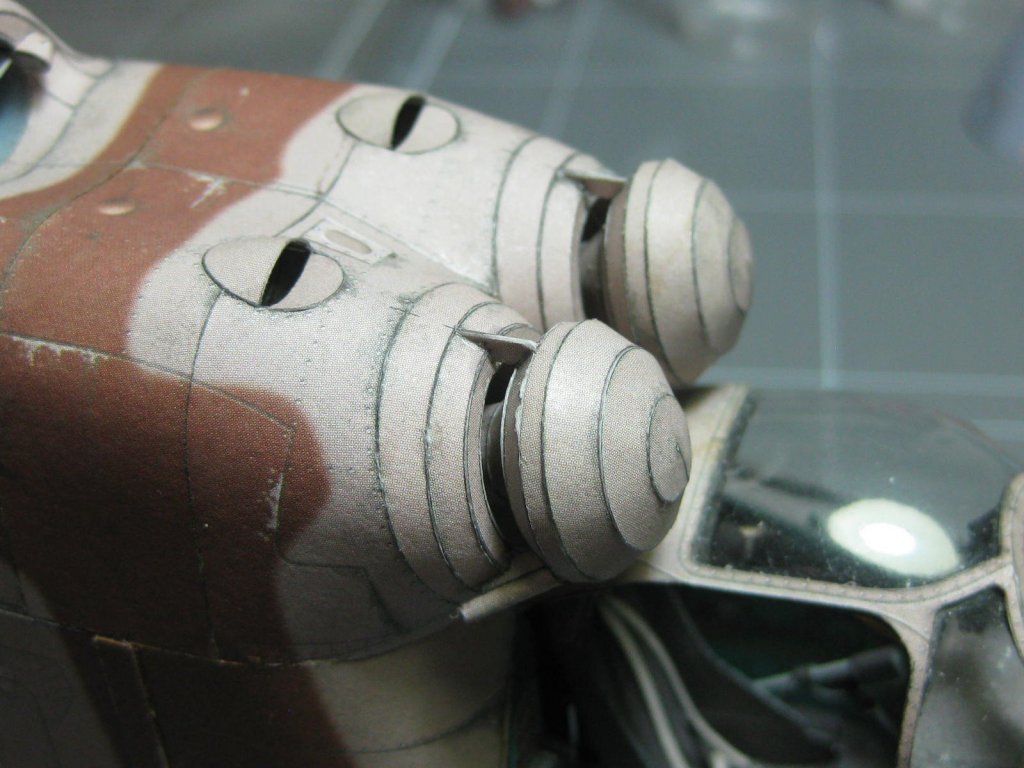
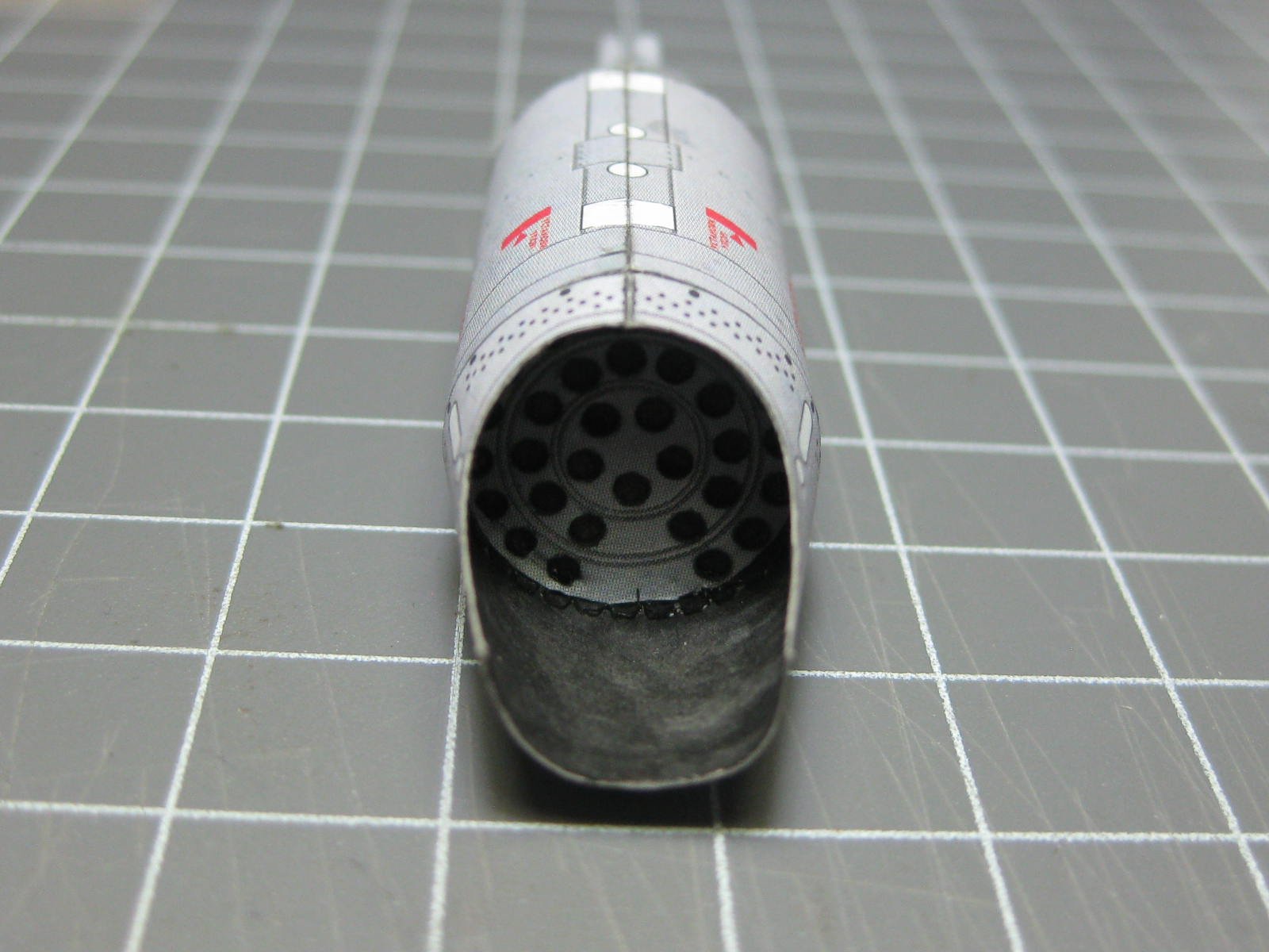
Oops, my bad . Sorry about that Pav. Yep, I have to agree with that. However (blowing my own trumpet here ) I think my turbine inlet fascia turned out better than his. Then again, if I hadn't found his build log where he warned about the potential for error it would have turned out a lot worse . Brzdic's is the first pic, mine is the second : Nice work on the lantern Pav. Danny
-
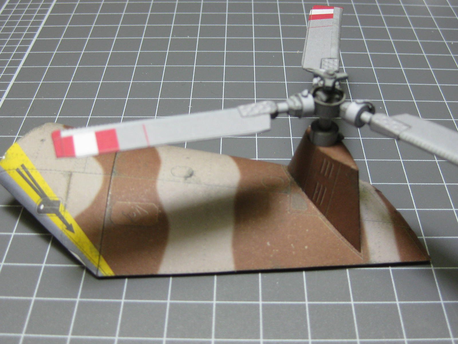
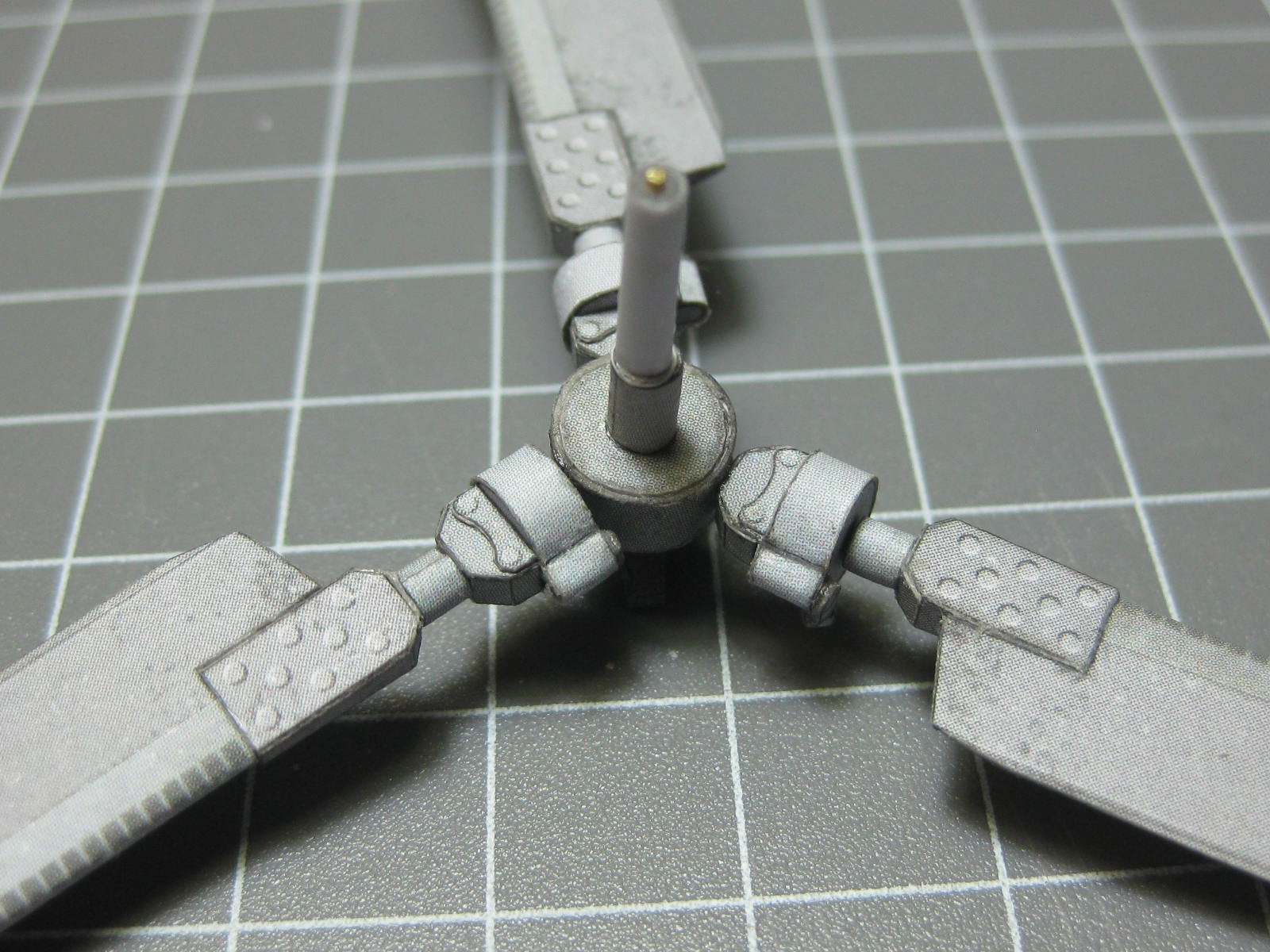
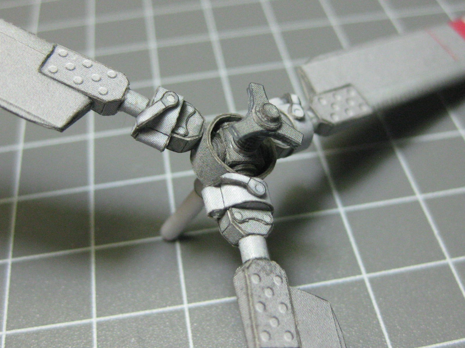
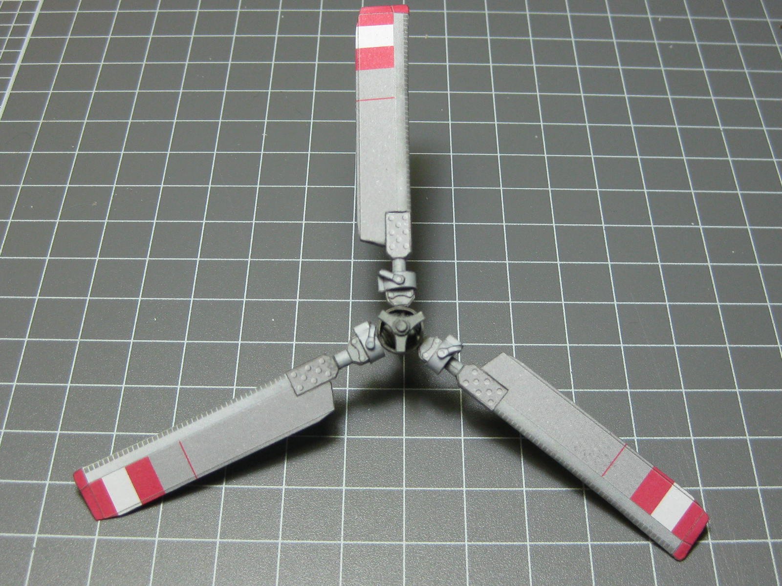
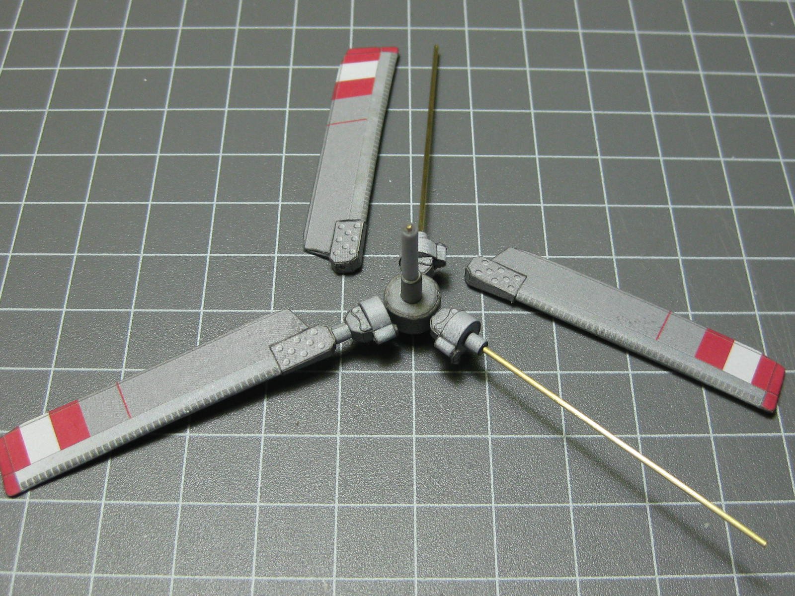
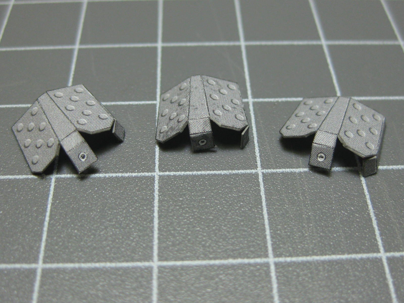
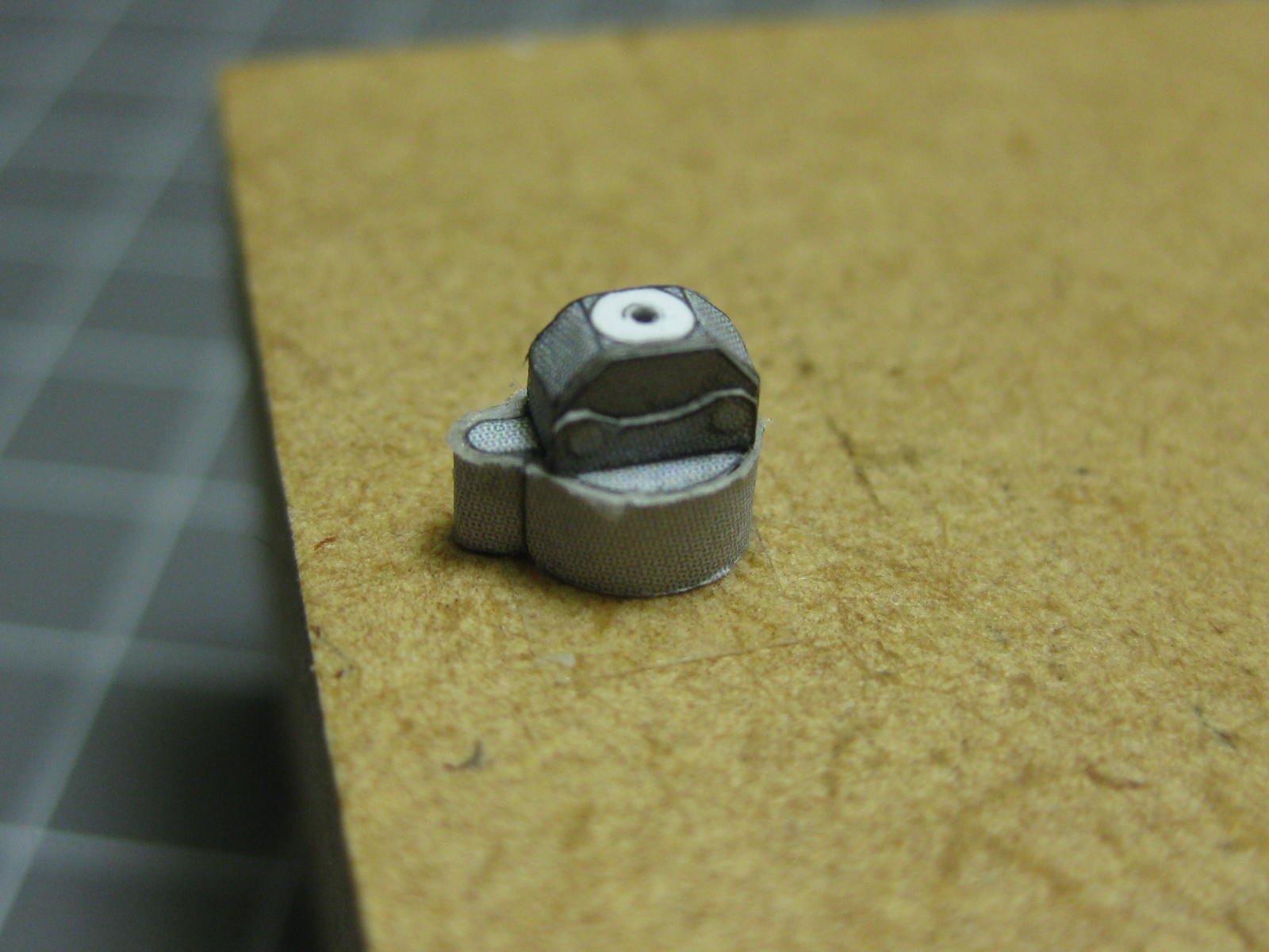
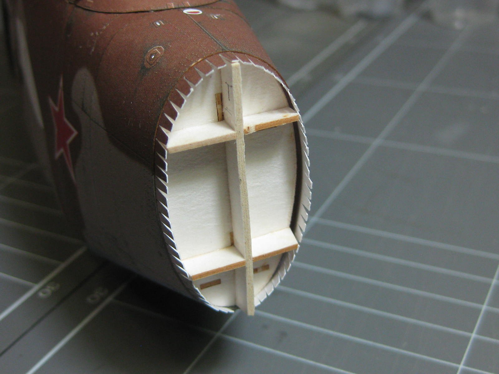
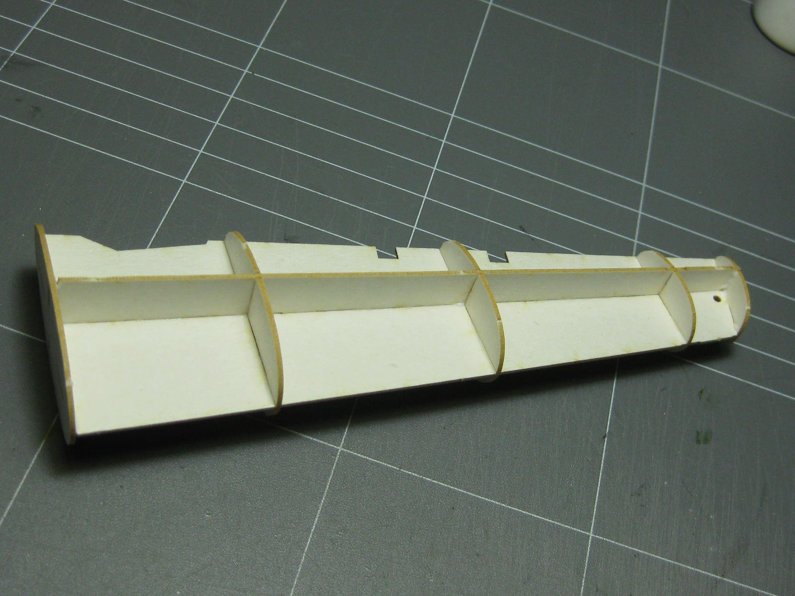
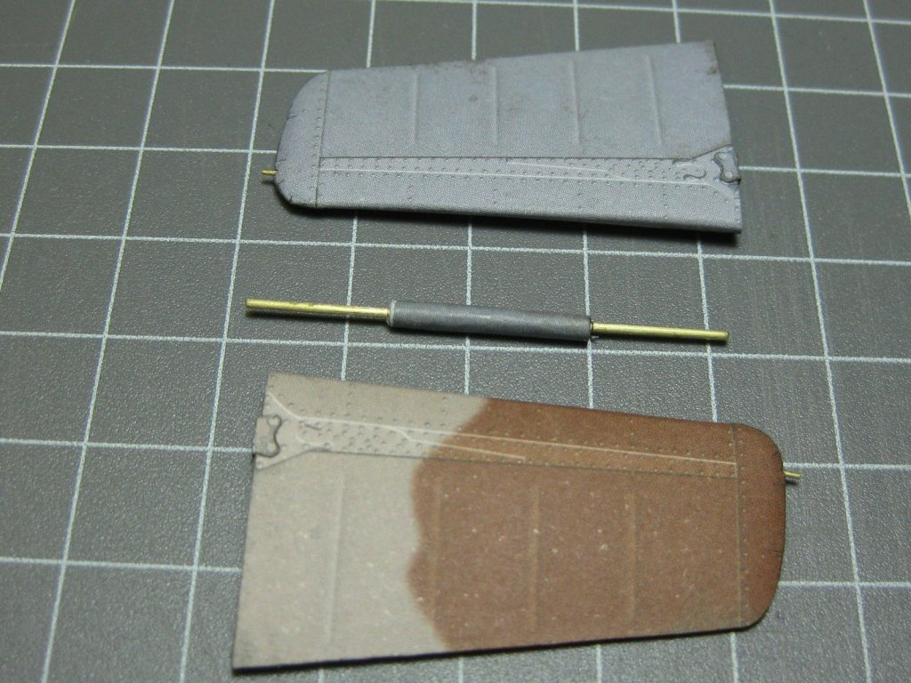
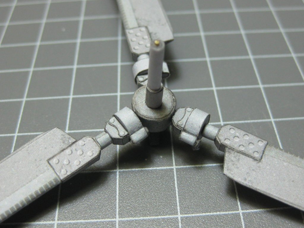
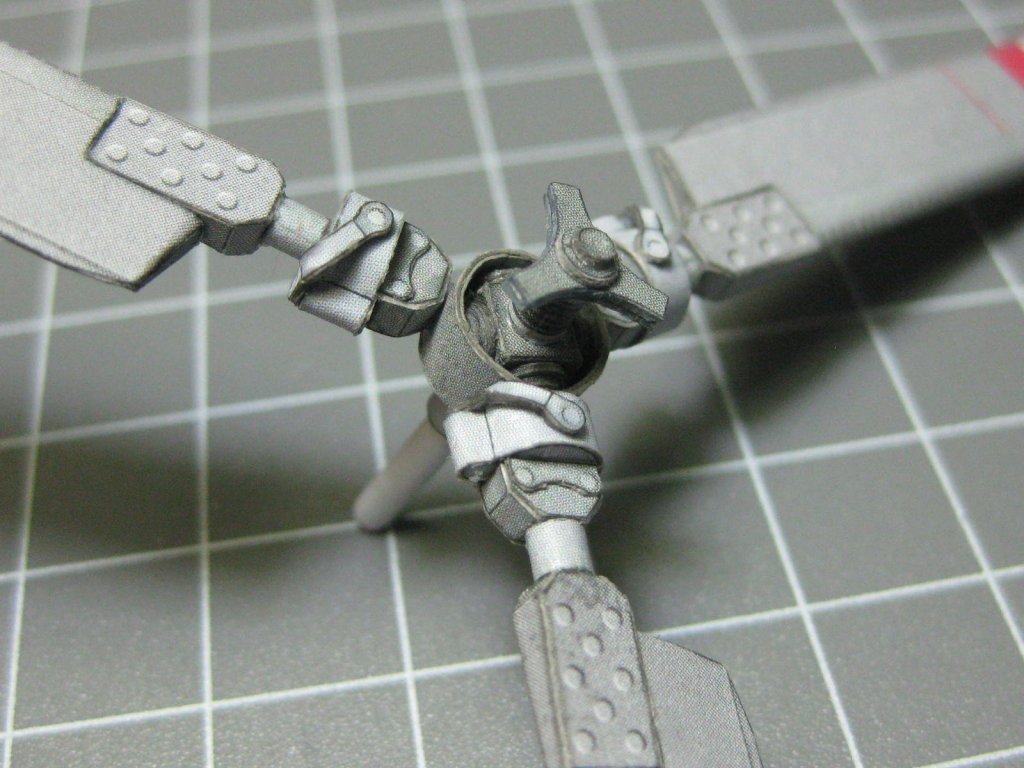
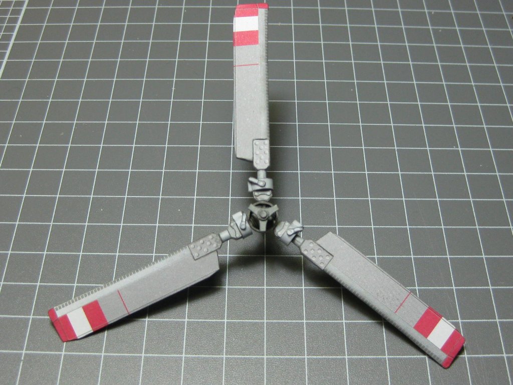
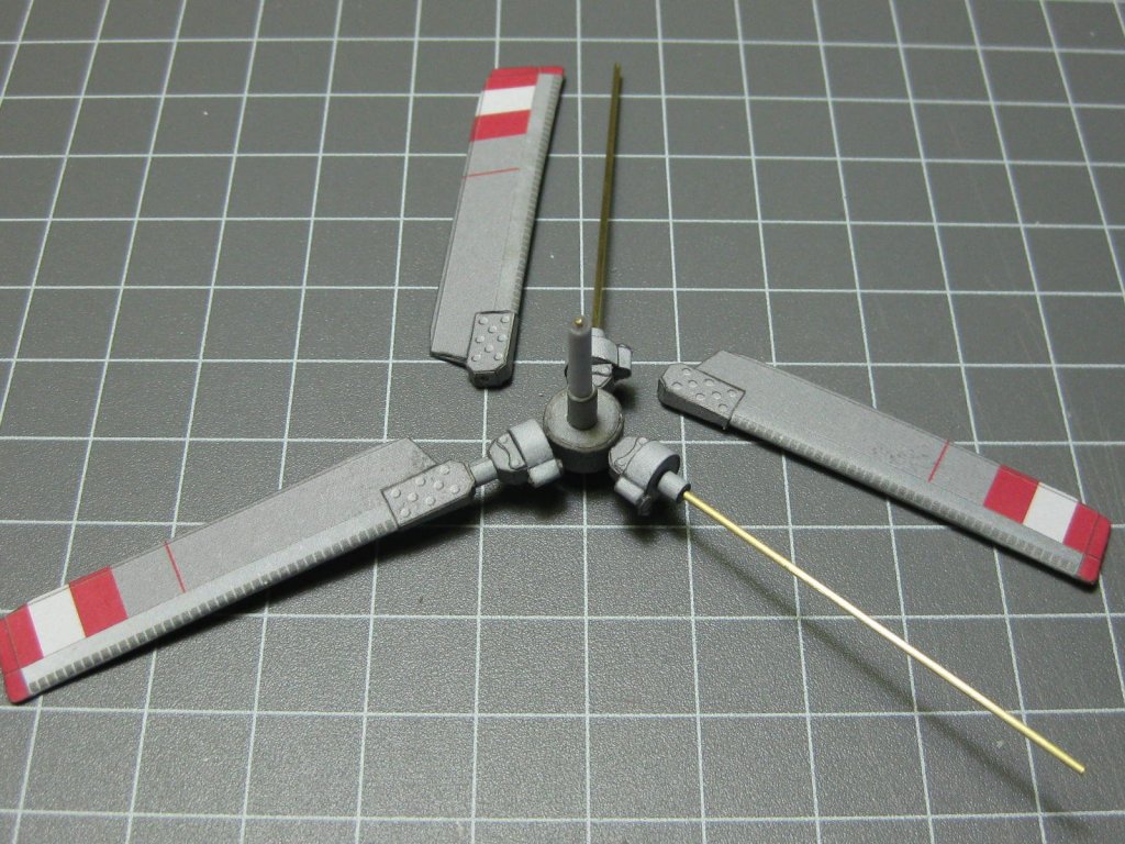
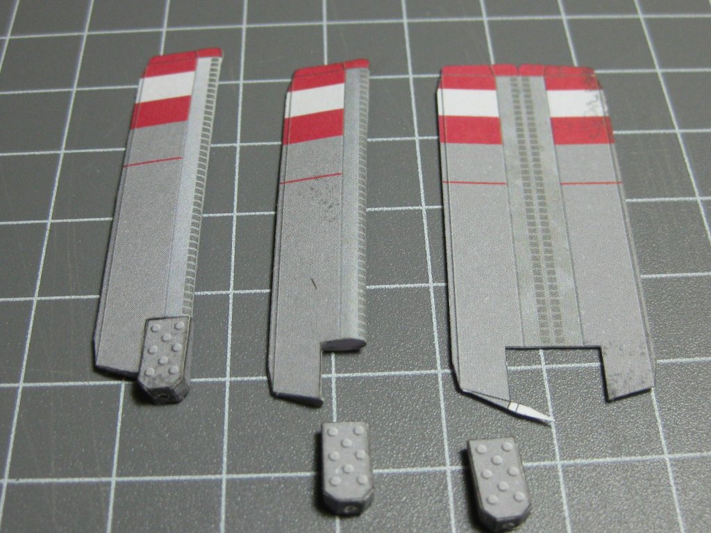
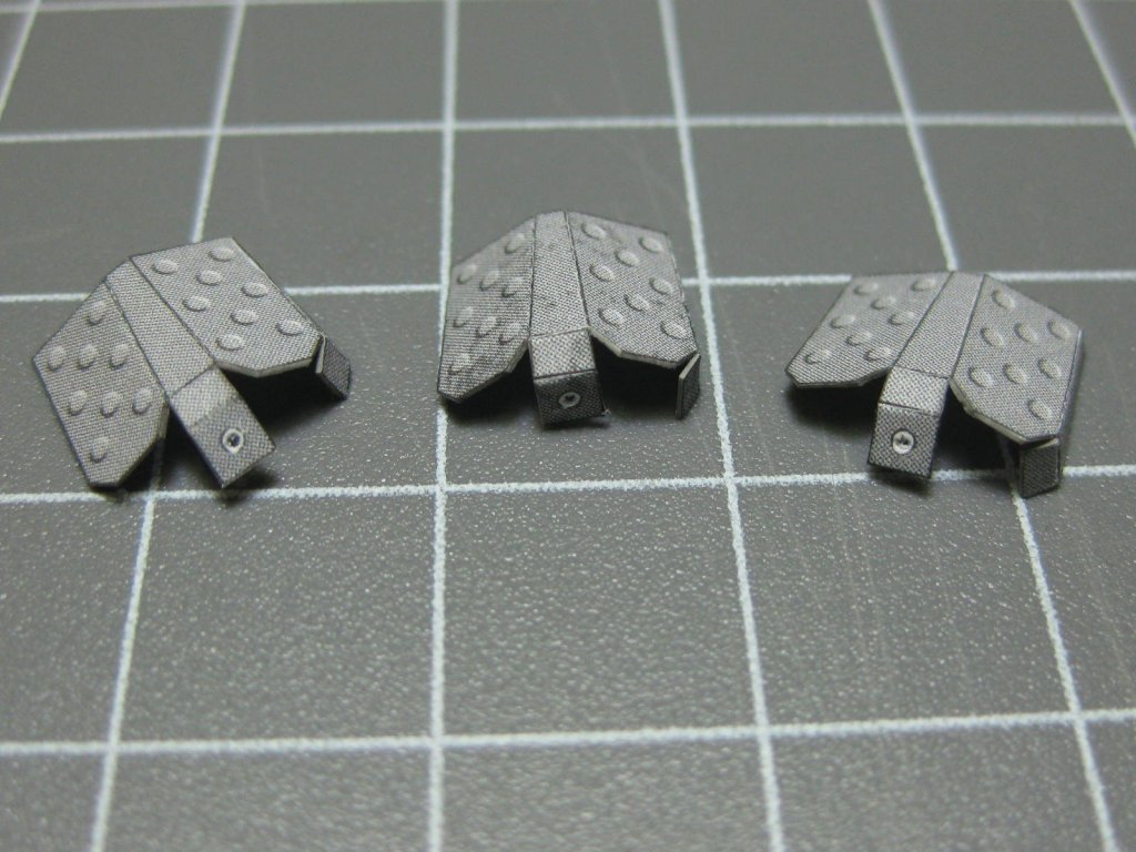
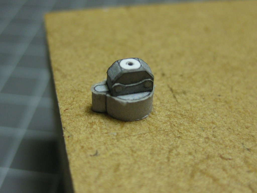
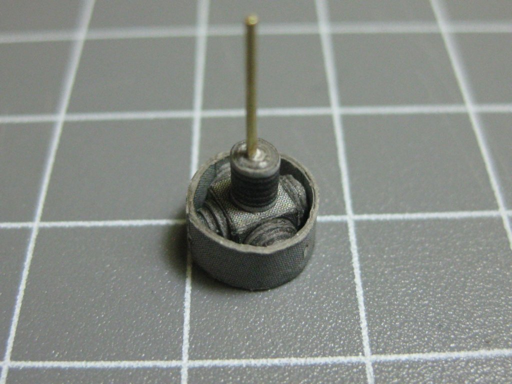
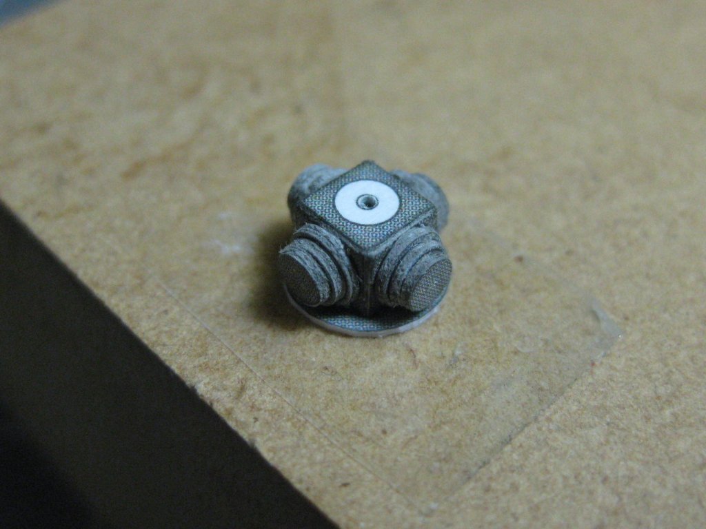
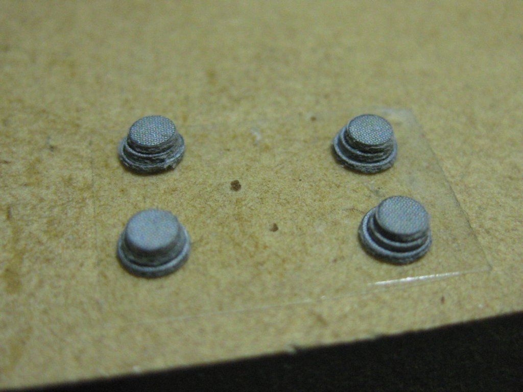
I continued further toward the tail, completing the fin and elevators. These went together without too many dramas. I've changed my method of skinning to a certain degree. I now glue the skin together along the edges and slip it over a faired framing, doing more fairing until it's a good fit and the skin slips in easily before gluing them together : Although it won't be fitted until the end of the build I made the tail rotor. This is quite a complex arrangement, and will be good practice for the main rotor later. Here are most of the parts : First part is a universal joint : The rotor arms. Wire is used for strengthening : The finished assembly : Danny


- 127 replies
-
- 14
-
-
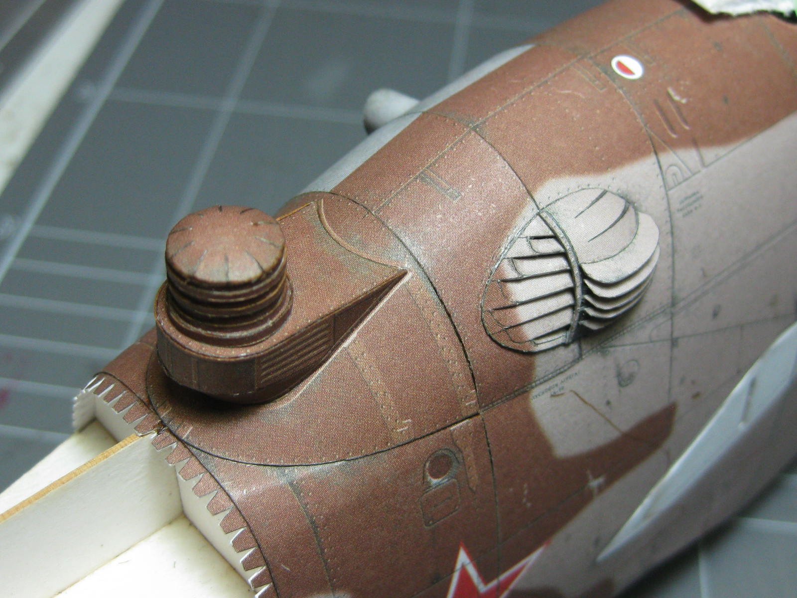
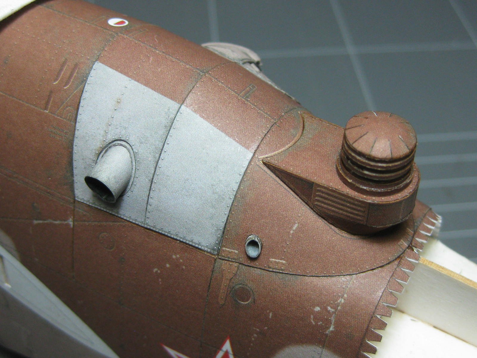
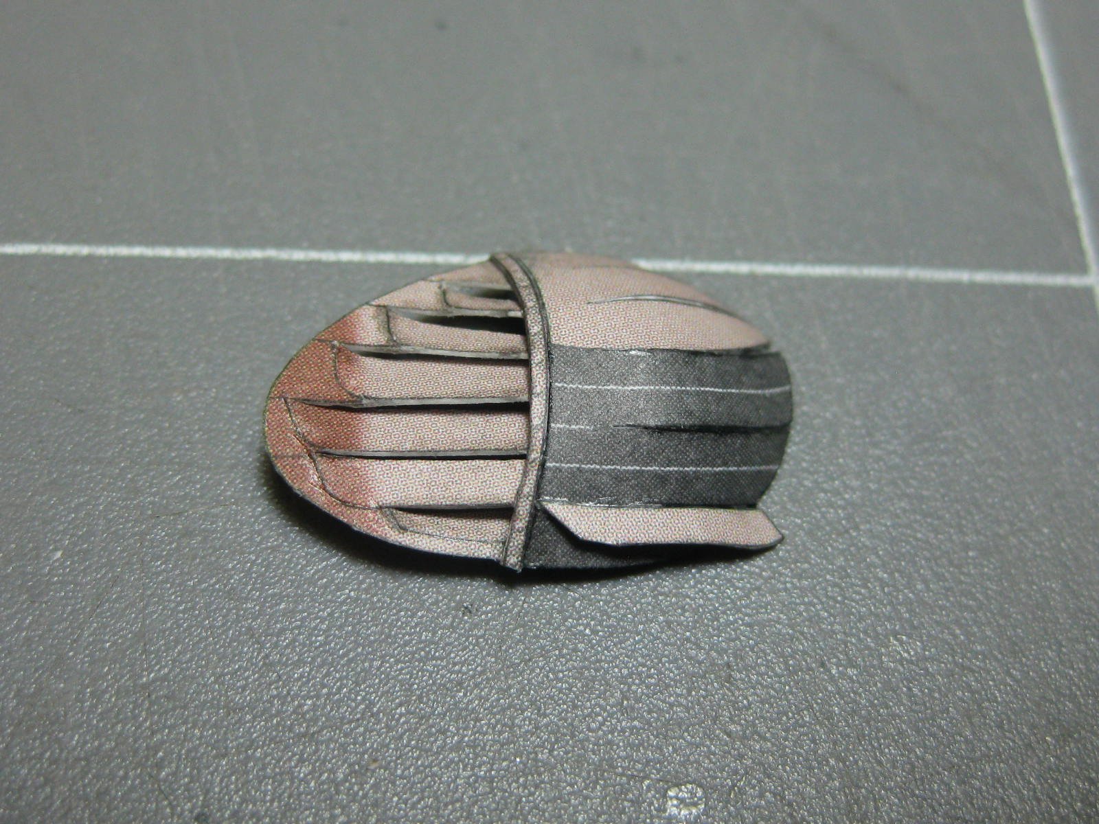
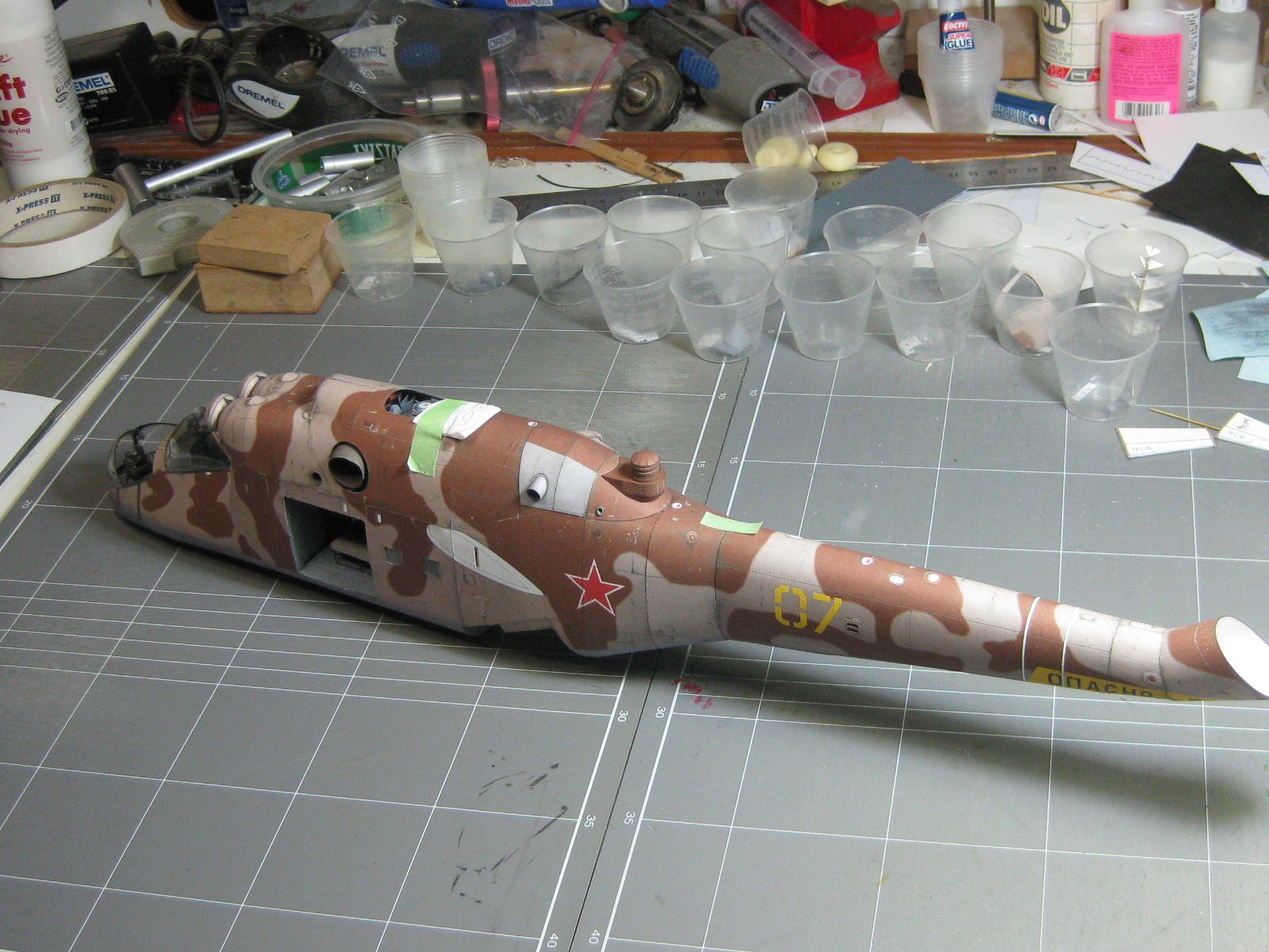
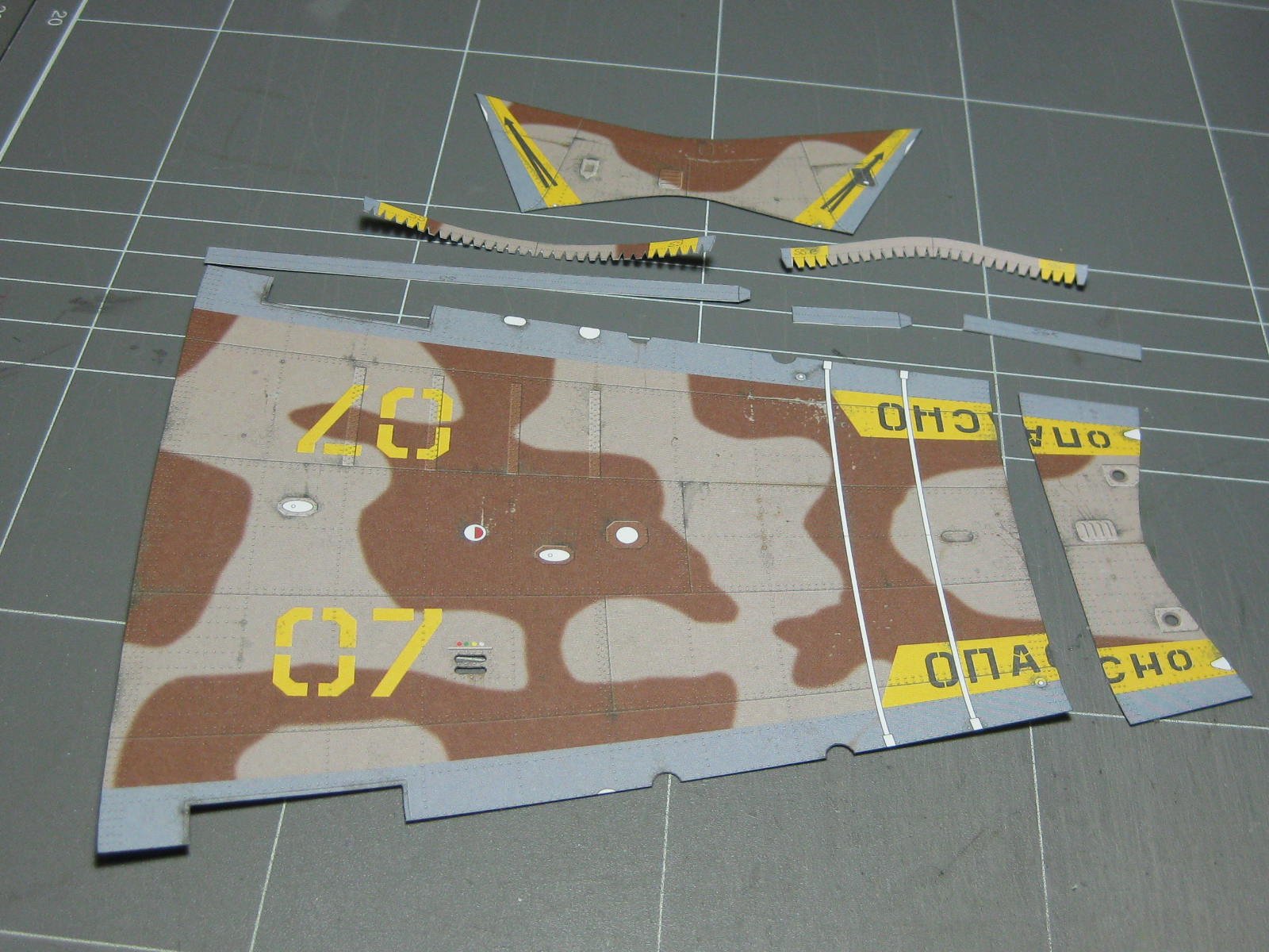
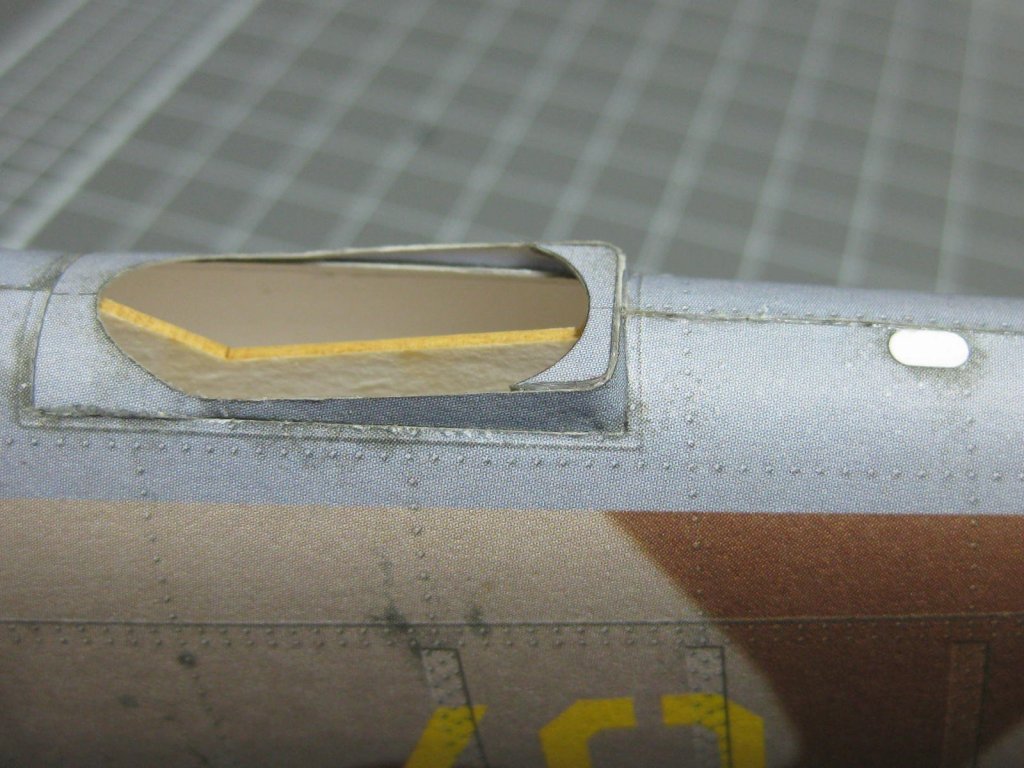
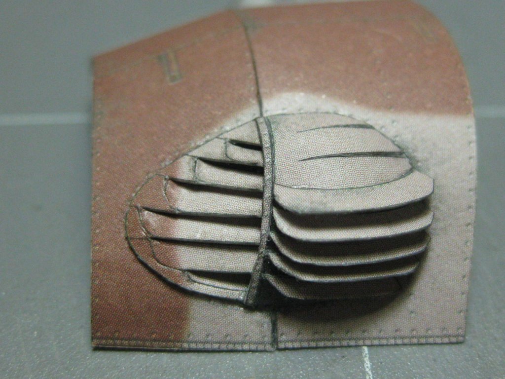
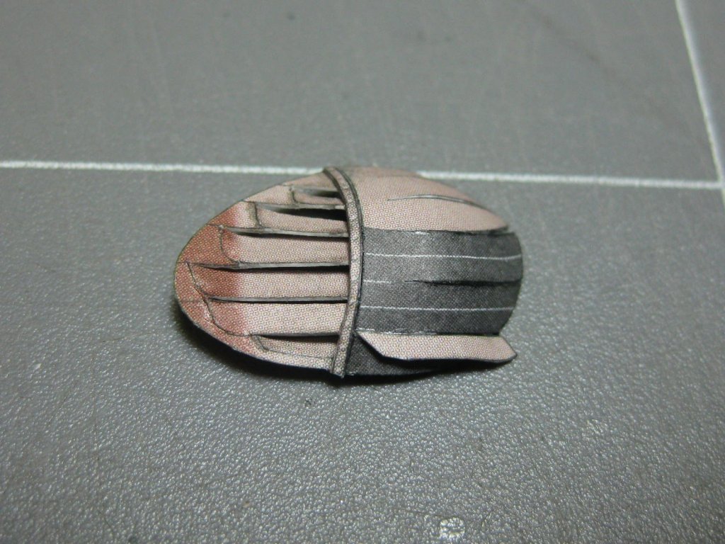
Thank you all once again . The next section of skins have some interesting pieces fitted to them. There is a louvered panel which took me over a day to make : Another fun piece on the back skin : The next section toward the tail : The Czech guy thought he had a problem with the length of the framing, and it is actually shorter than the skin, but with the right amount of fairing the problem became obvious and mine fits perfectly. However I did make a bit of re-enforcement where it attaches to the forward section. I'm not fitting the two sections together until most of each has been completed for ease of handling. I've dry-fitted both sections together and the fit is perfect : She's going to be BIG : Danny


- 127 replies
-
- 12
-
-
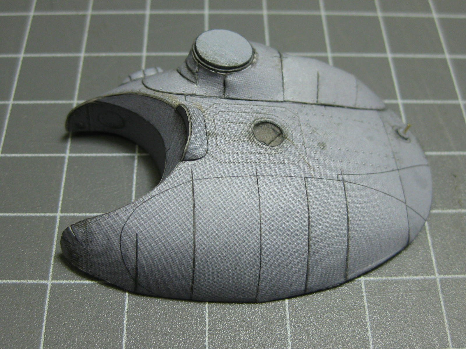
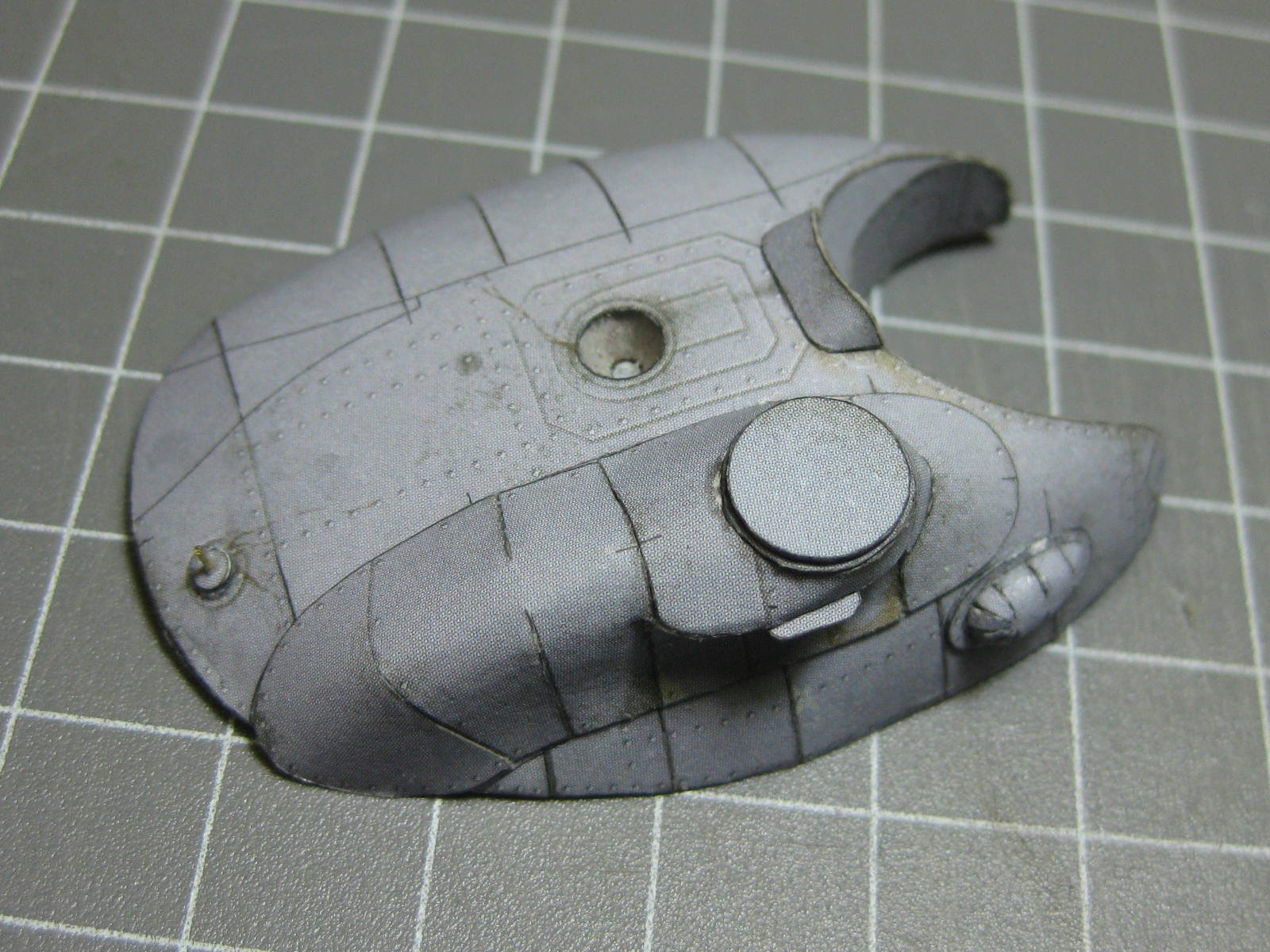
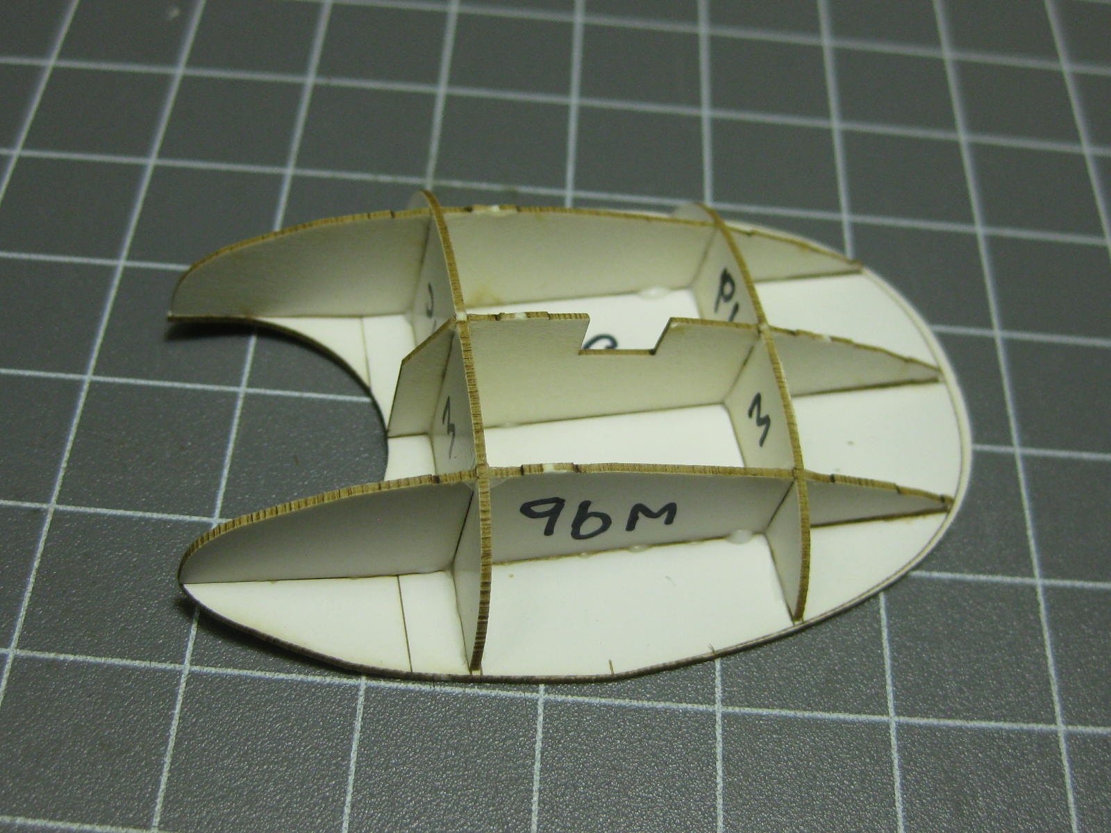
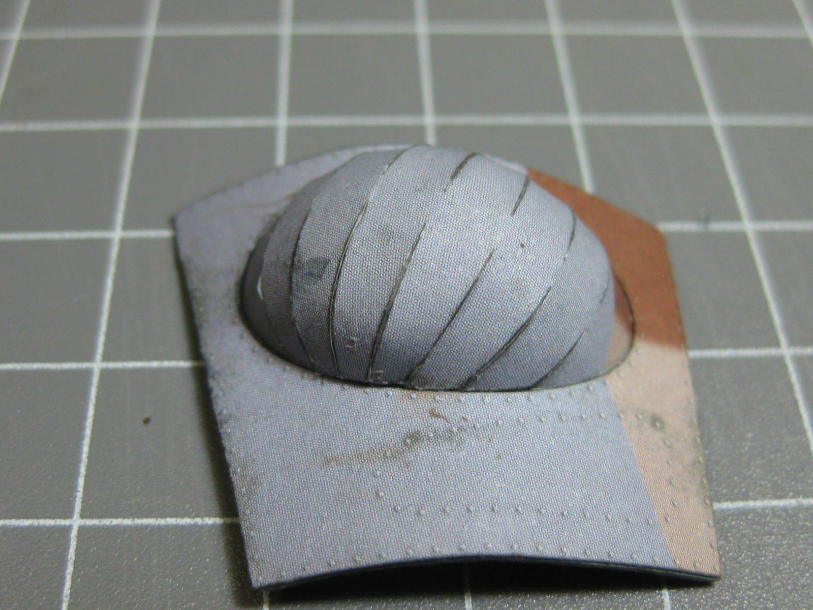
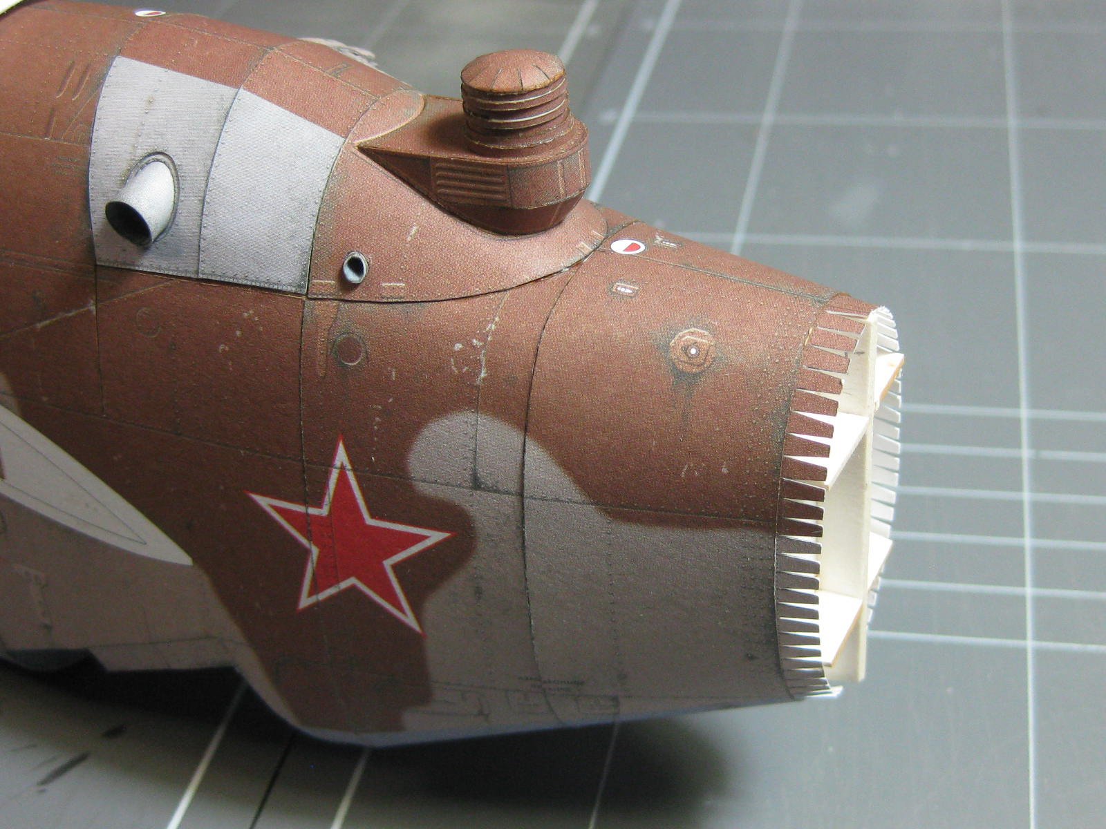
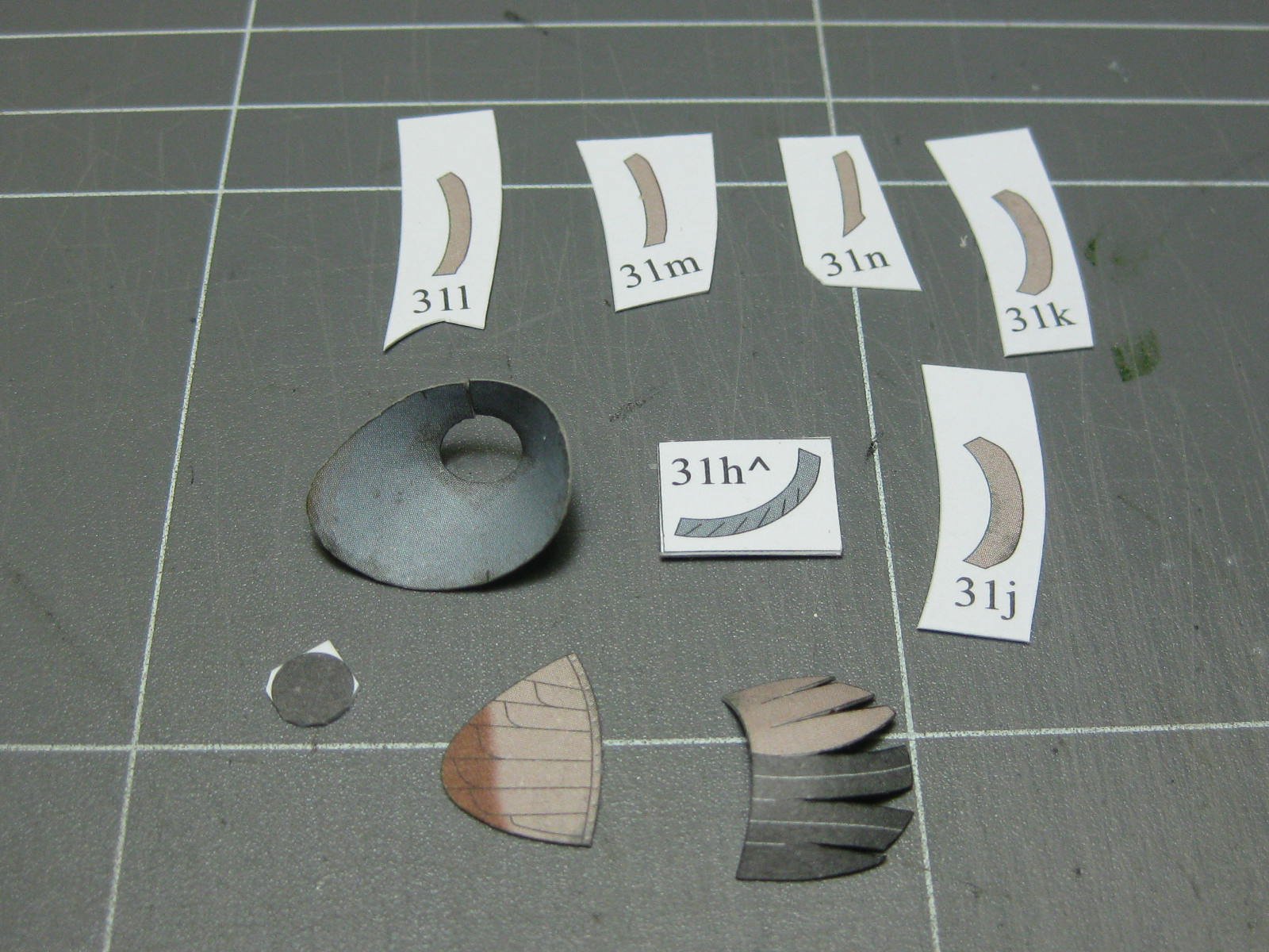
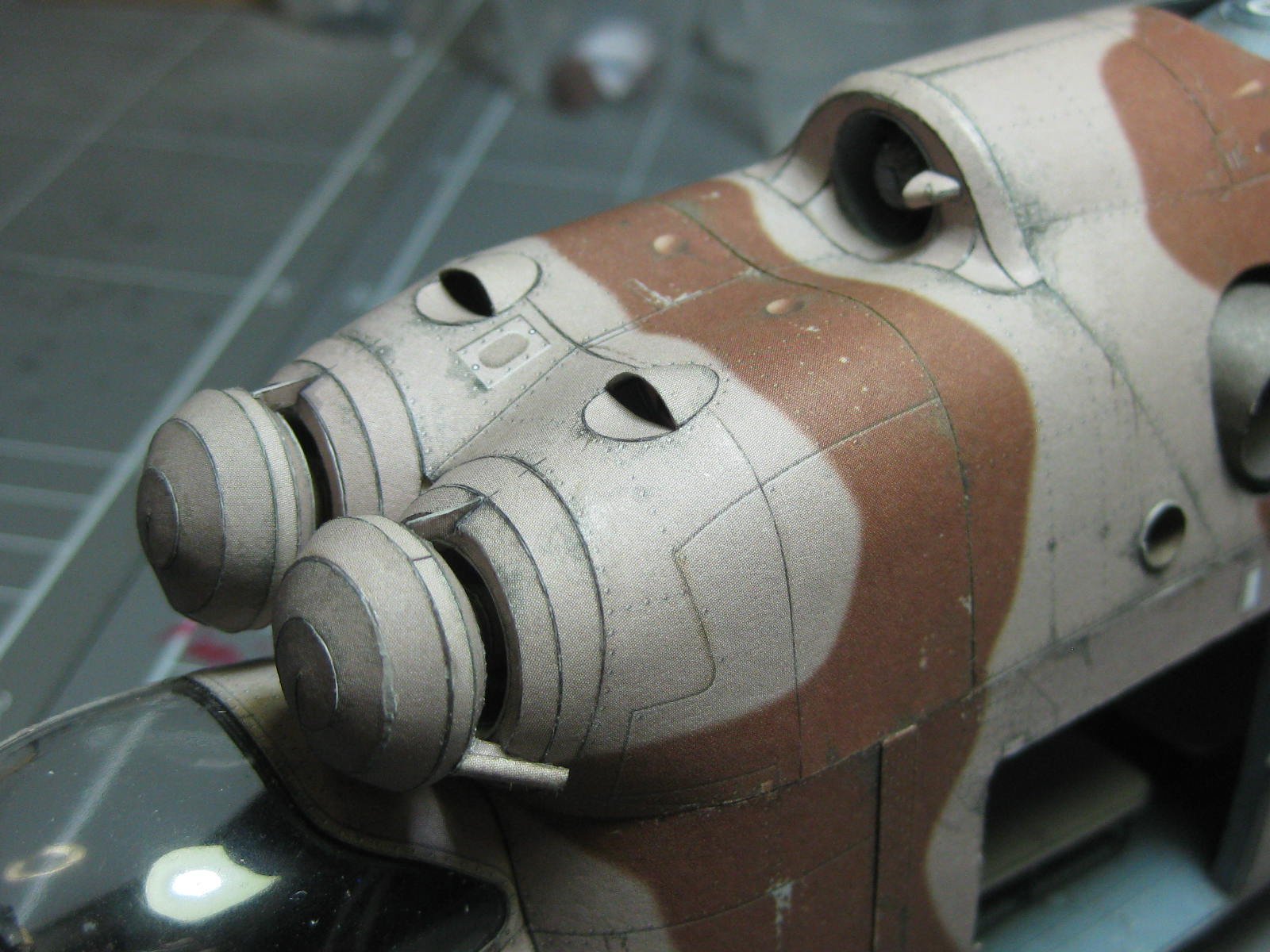
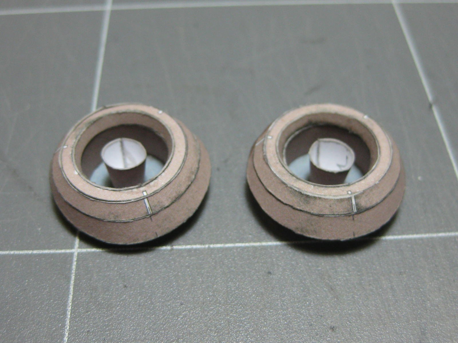
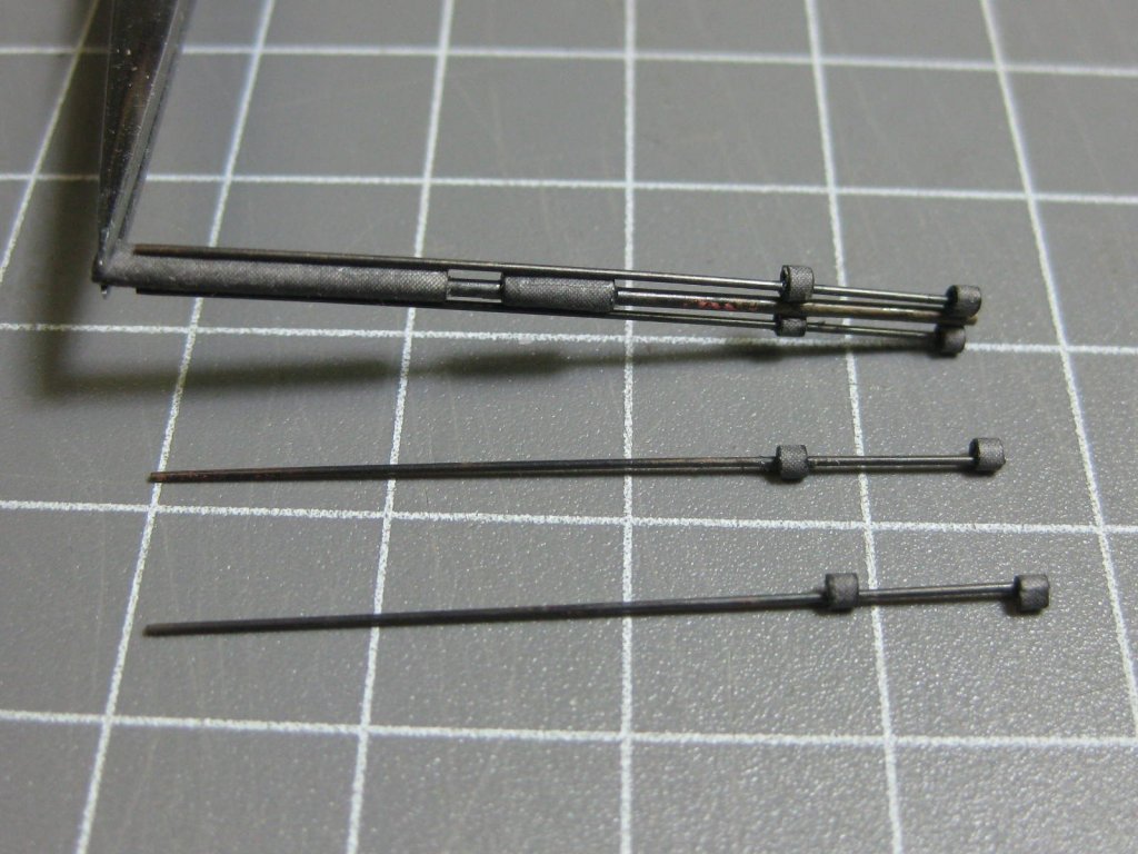
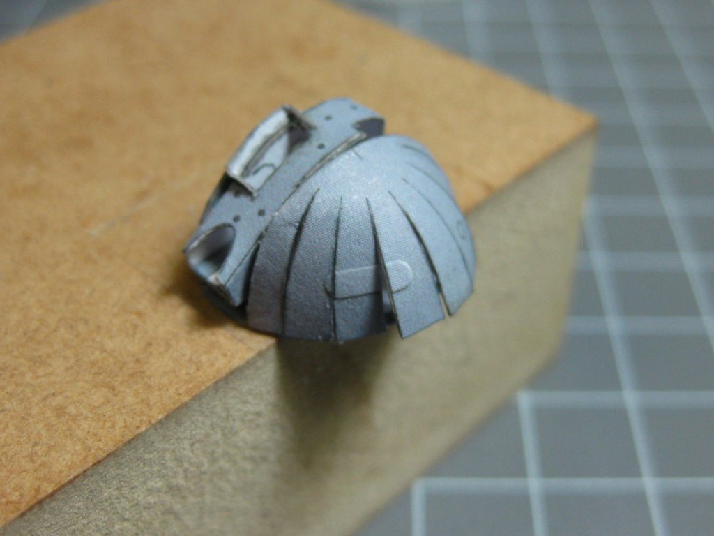
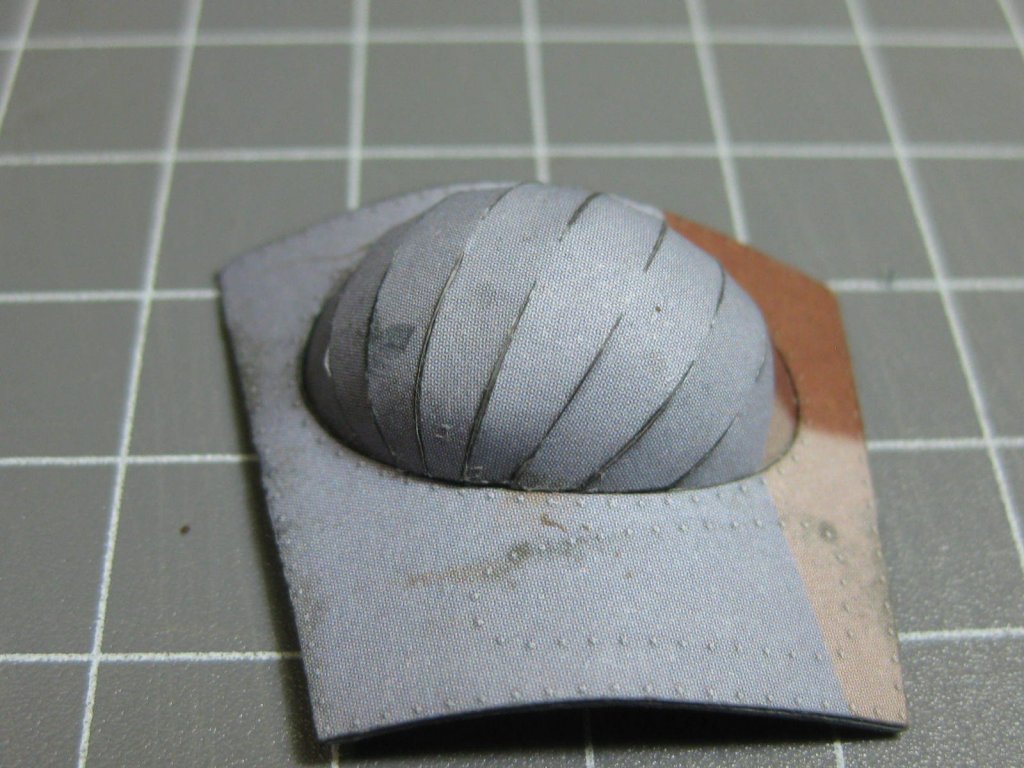
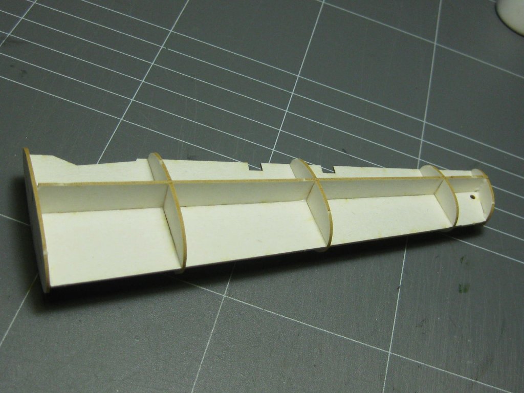
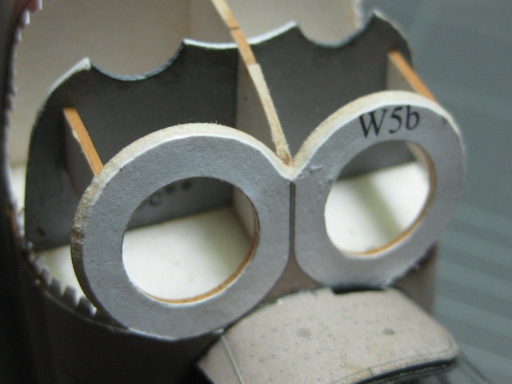
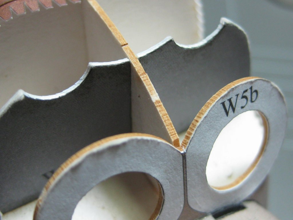
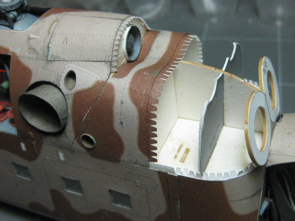
Next to be made is the central turbine. I'm pretty happy with the way the rotor shaft turned out : The fascia surrounding the turbine wasn't real easy to make : I prepare several skins at once to make sure everything fits properly. A fair bit of dry fitting is involved : I found another guy on a Czech Papermodelling site (needs Translator) who has built this model. This bloke is above my skill level, and his build log has come in very handy when I get a bit stuck in the instructions. He's also documented most problems he's had along the way so I can (hopefully ) avoid them. This stage was one of those, and I'm very grateful to him. Apparently he didn't fair some of the framing enough around the turbines, so I made sure that I did : The turbines and air intakes fitted : Danny


- 127 replies
-
- 15
-
-
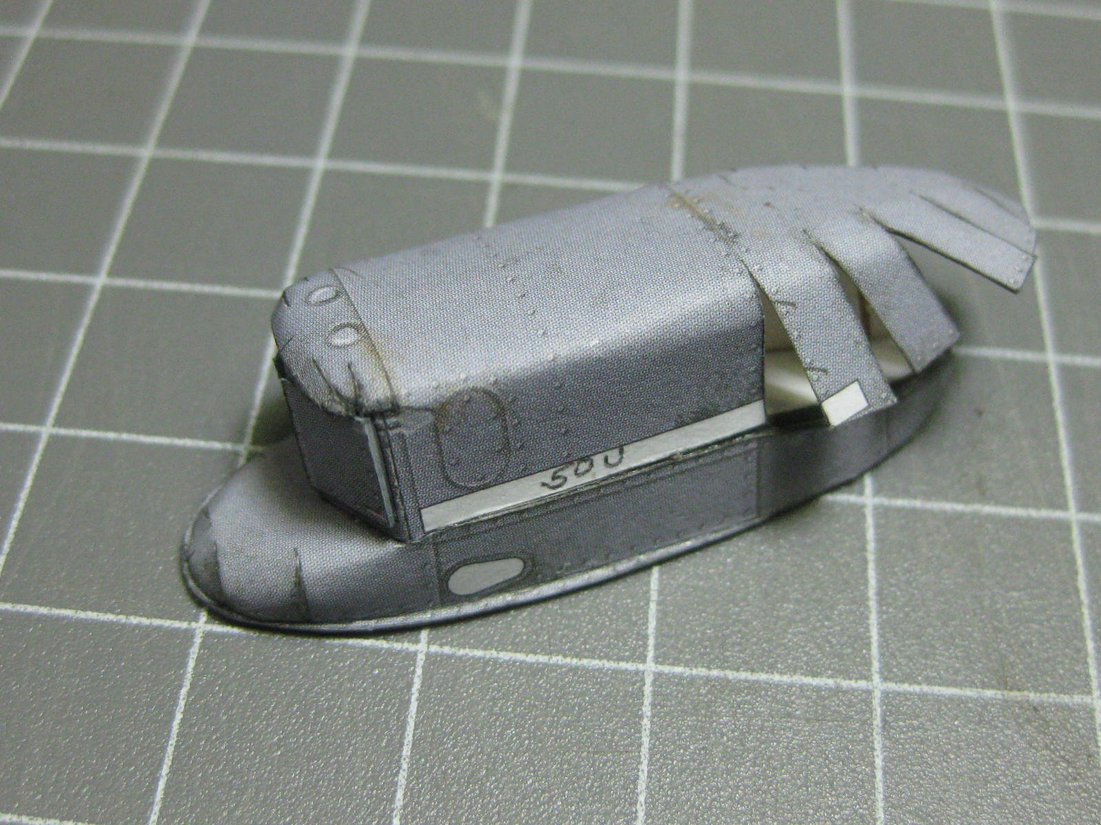
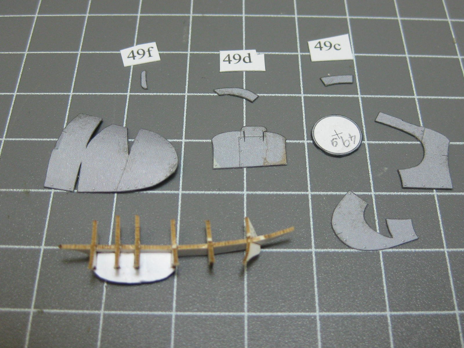
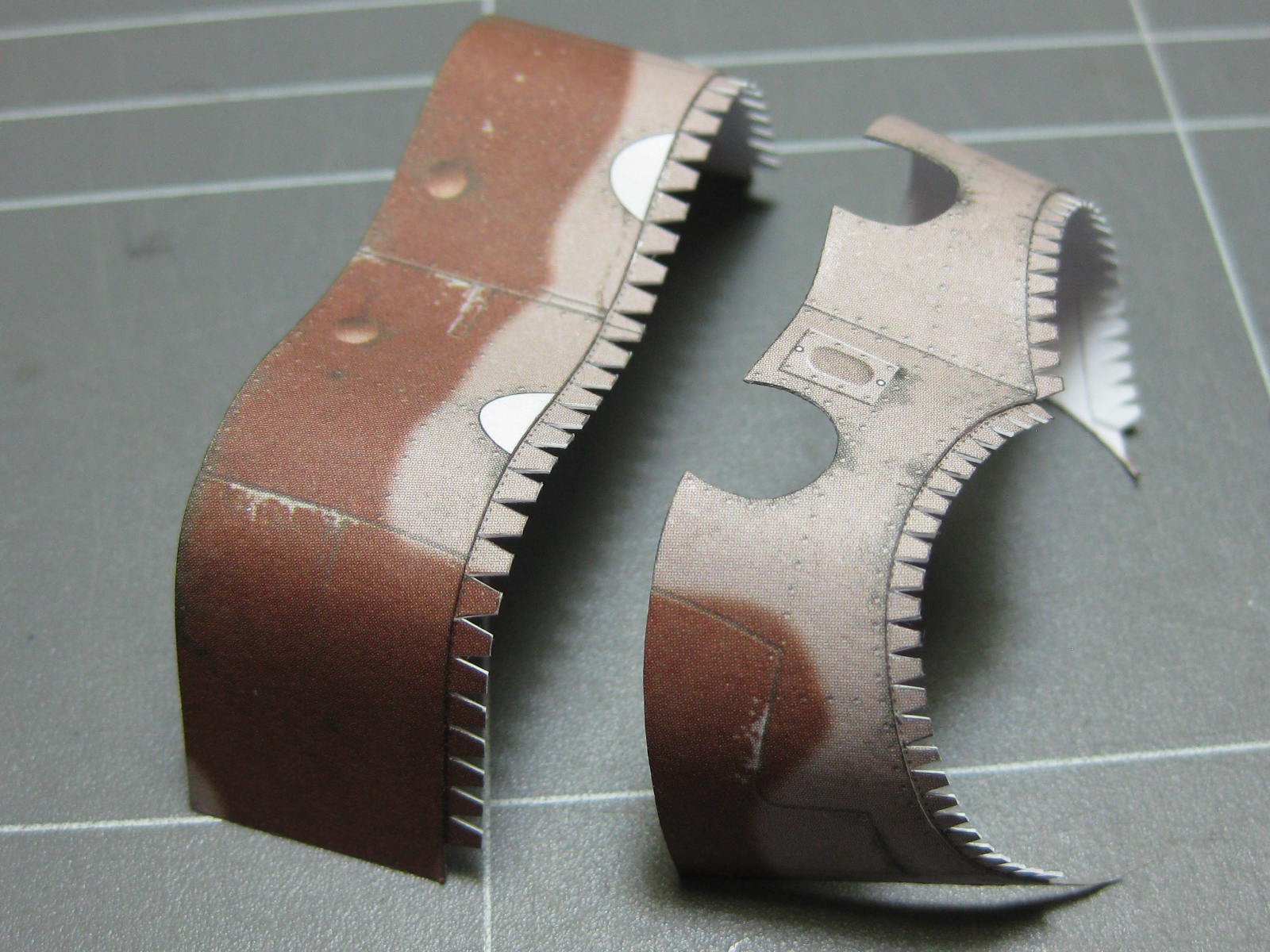
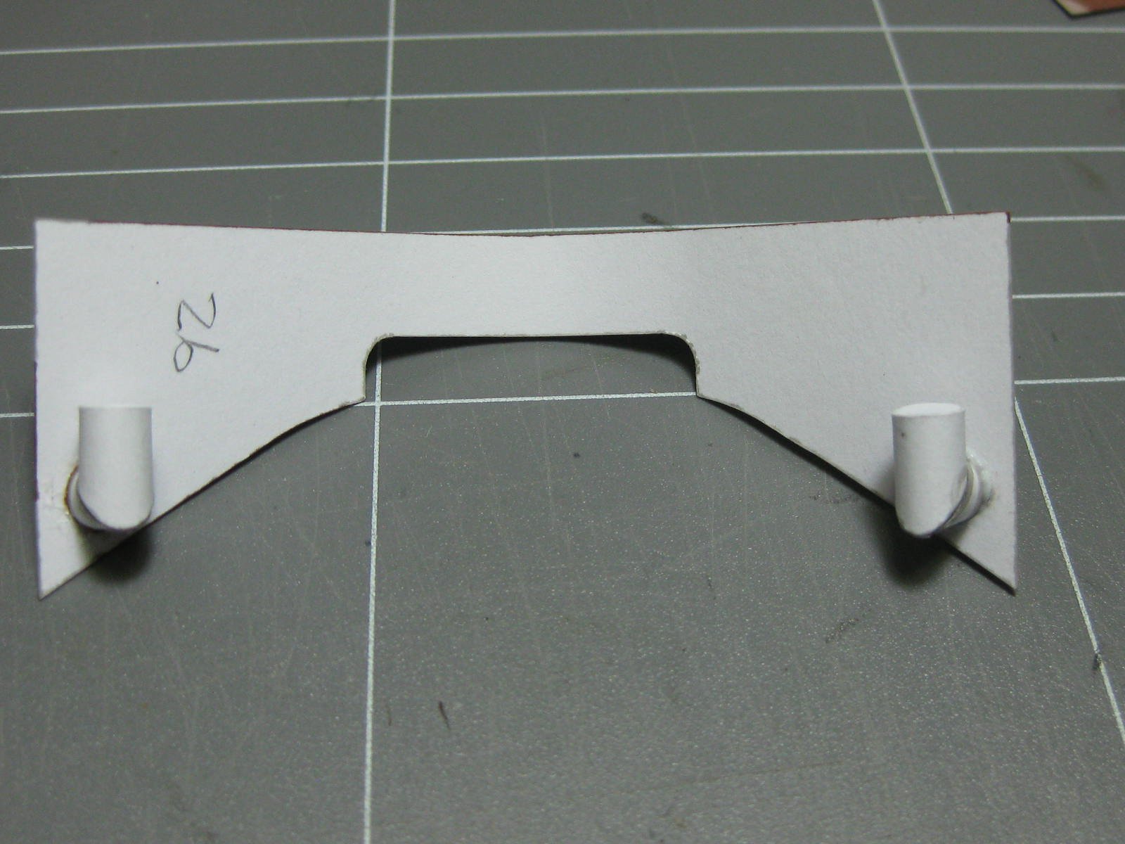
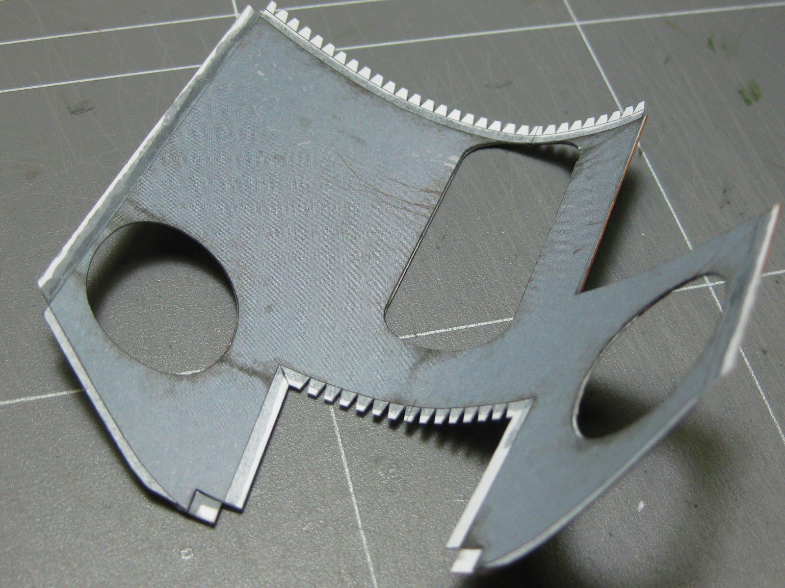
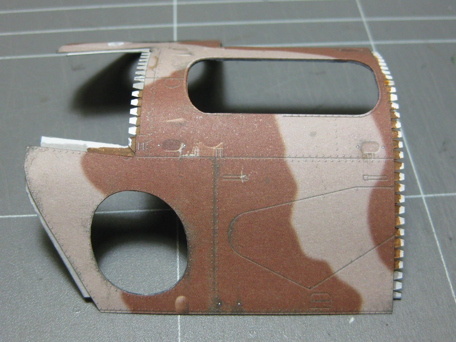
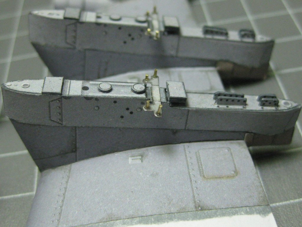
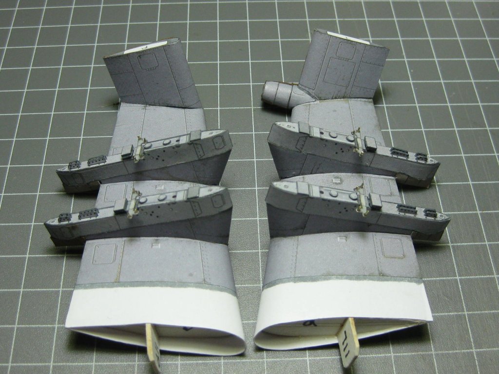
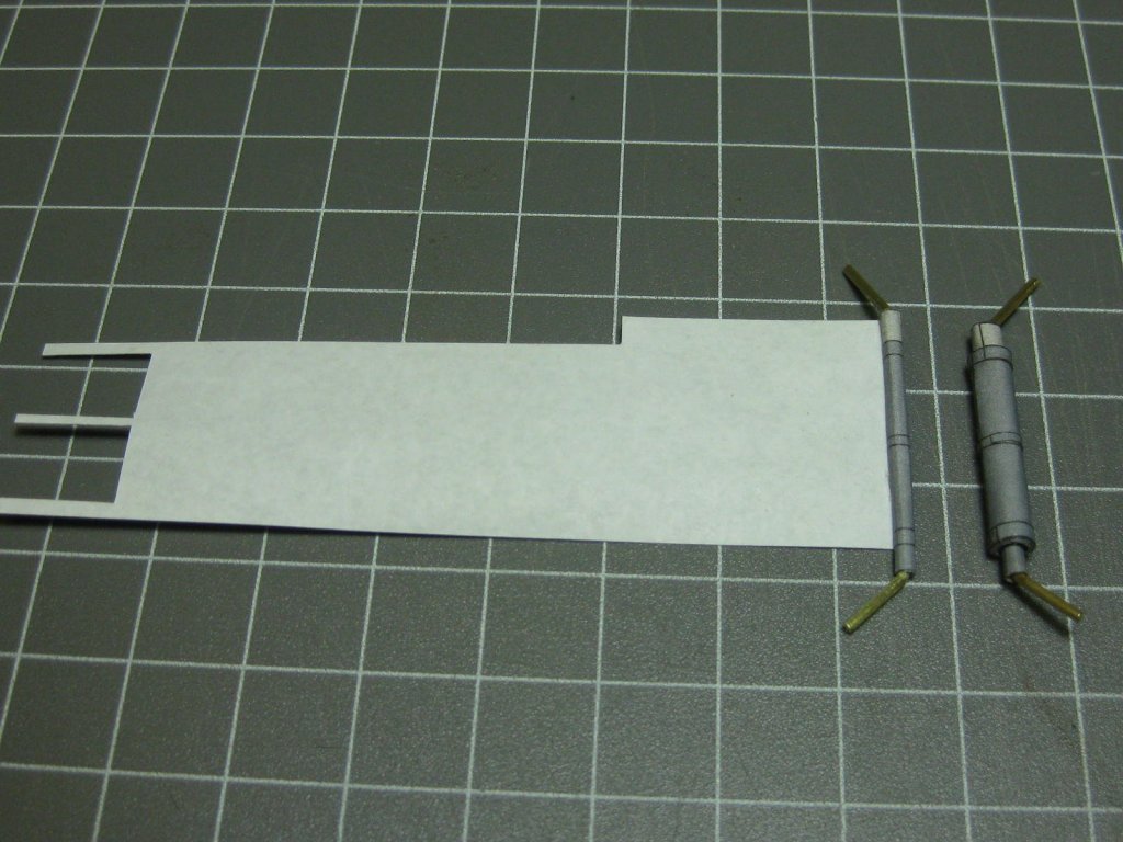
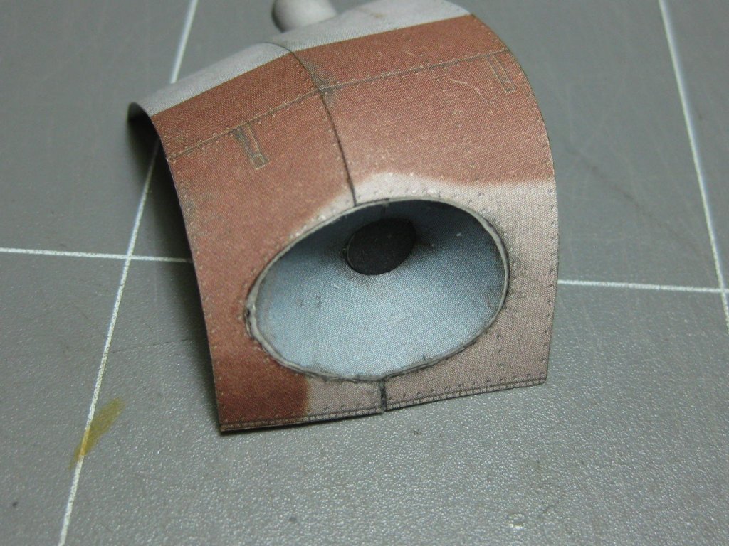
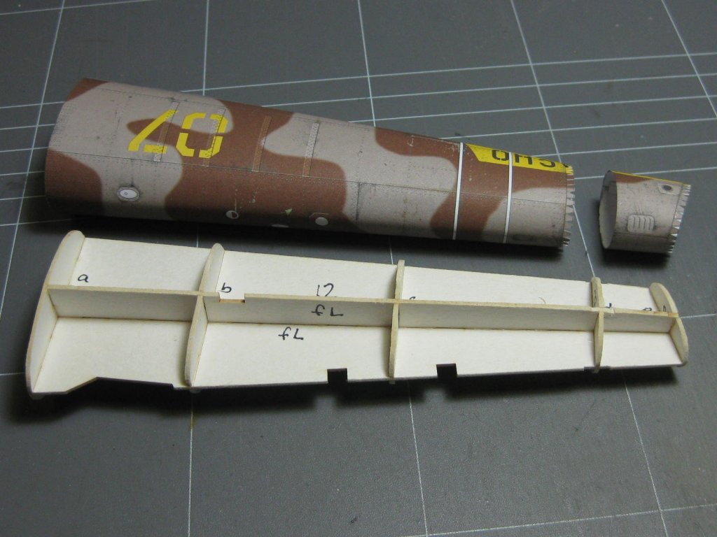
The two air intakes needed careful assembly. I did most of the work on a piece of MDF with double-sided tape attached to make it easier (read POSSIBLE ) to put them together : This is the skin that covers the transmission. It has an internal skin as well : The next skin forward has two 90 degree tubes fitted to it. They need to be fitted to the skin before it's fitted : Danny


- 127 replies
-
- 10
-


.JPG.7e0ca526945ad7f3387252f14a4b5f8d.JPG)