HOLIDAY DONATION DRIVE - SUPPORT MSW - DO YOUR PART TO KEEP THIS GREAT FORUM GOING! (Only 13 donations so far - C'mon guys!)
×


Dan Vadas
-
Posts
3,261 -
Joined
-
Last visited
Content Type
Profiles
Forums
Gallery
Events
Everything posted by Dan Vadas
-
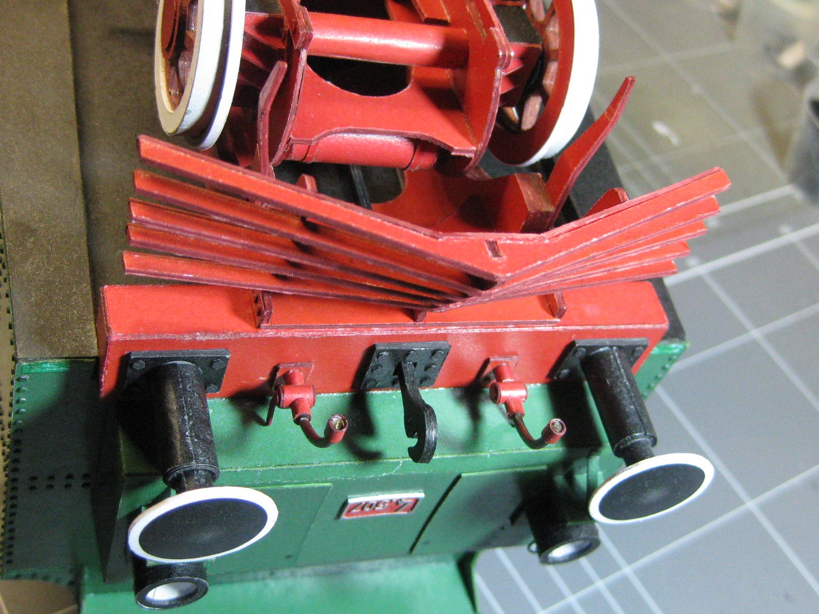
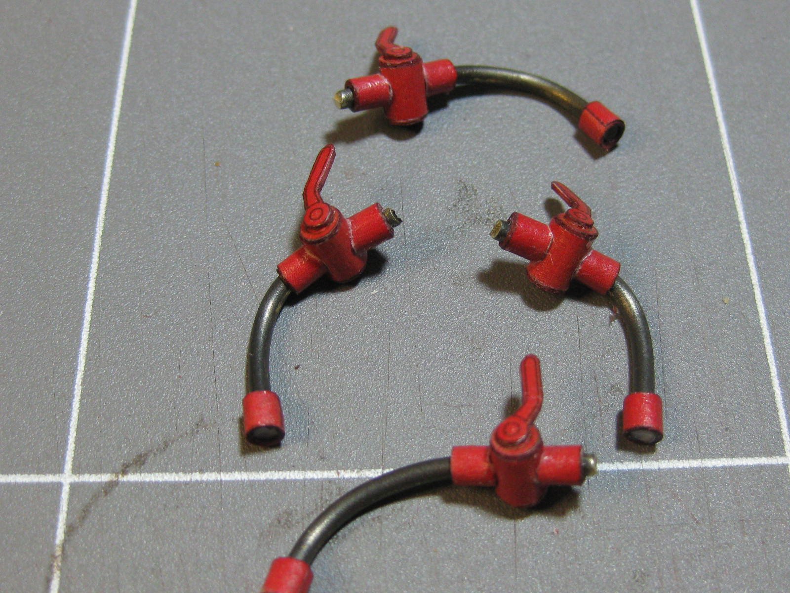
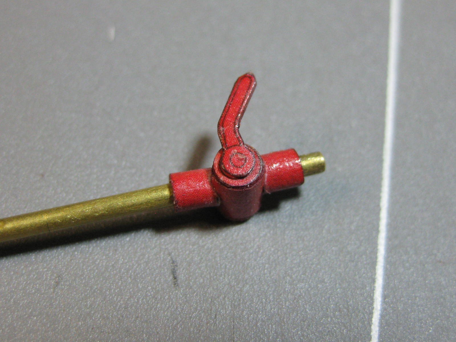
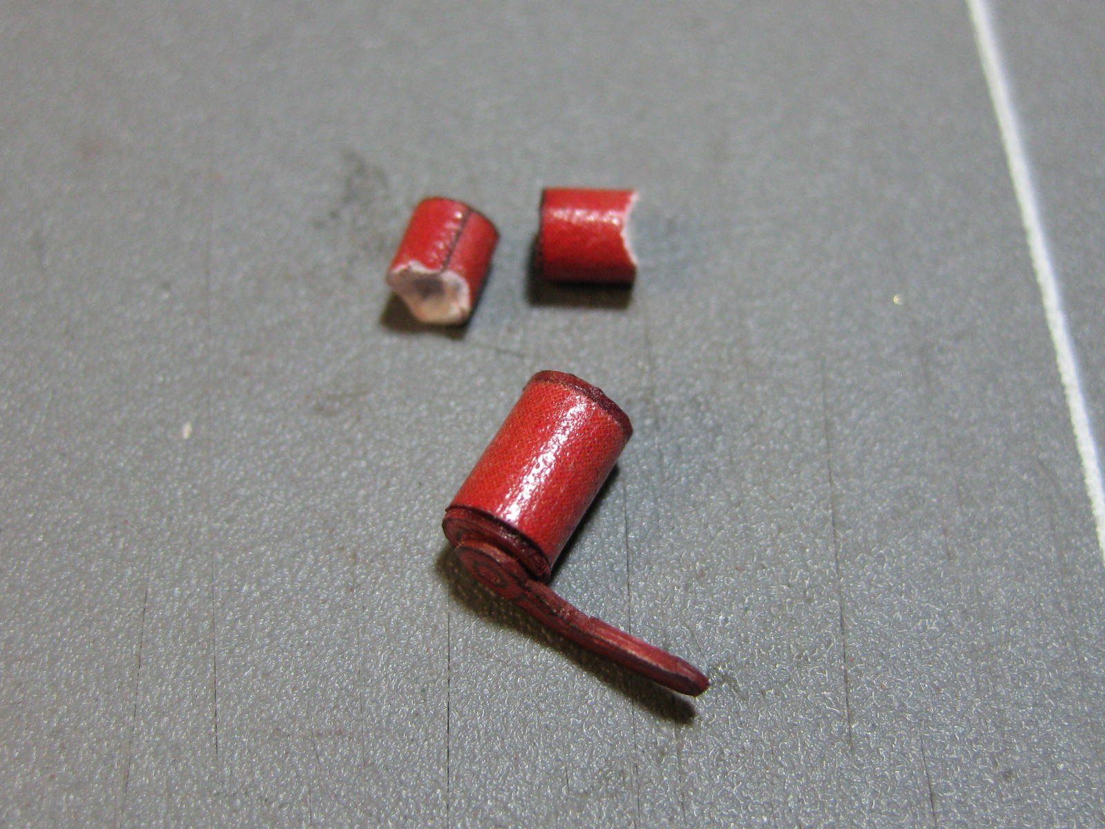
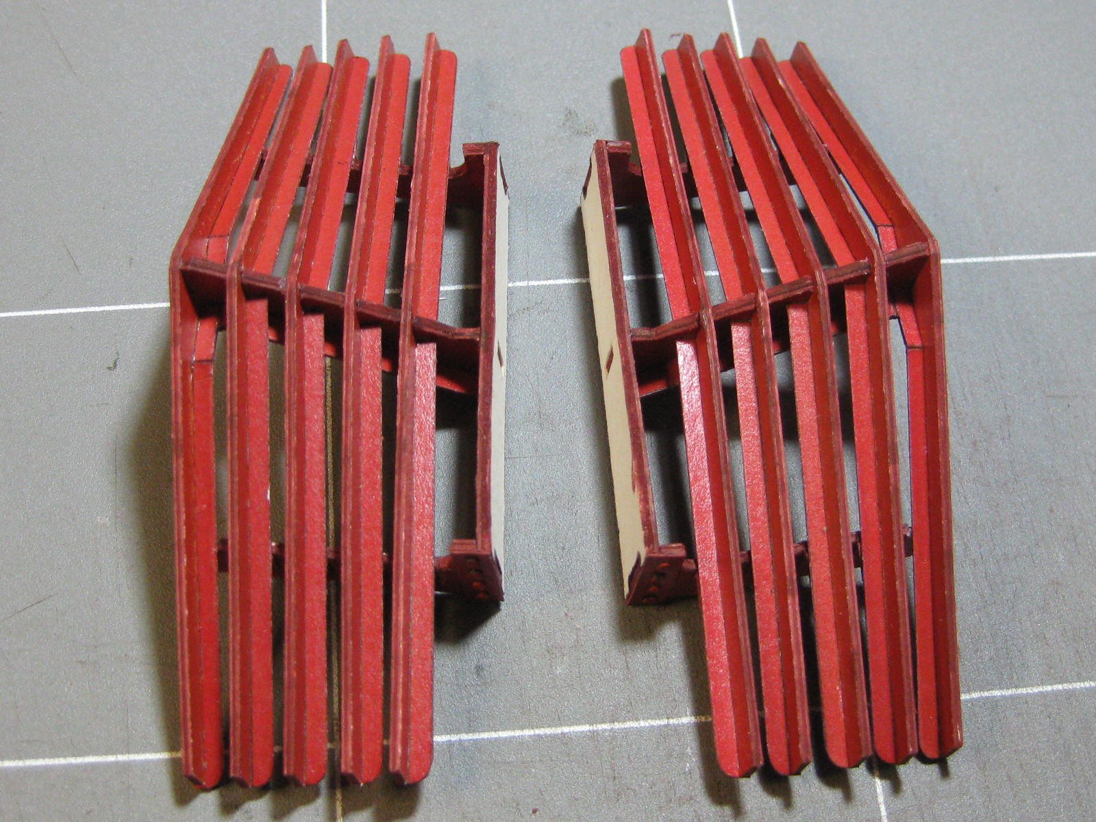
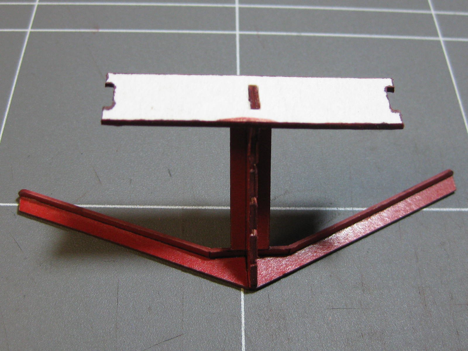
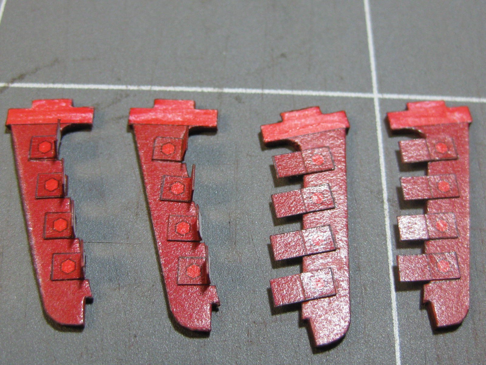
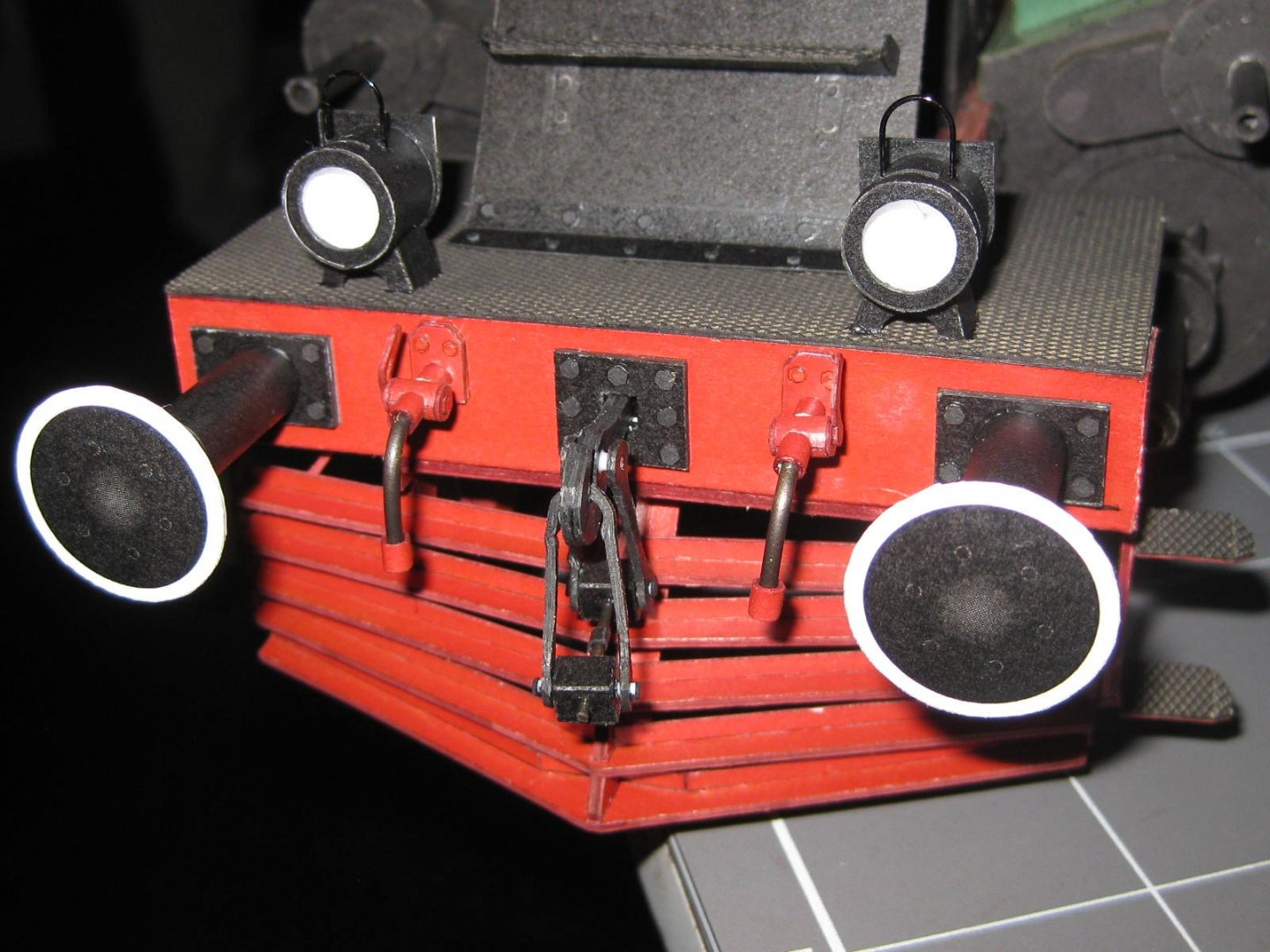
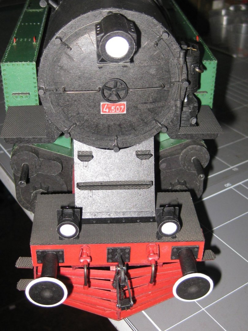
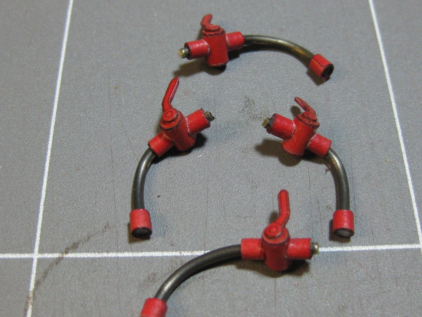
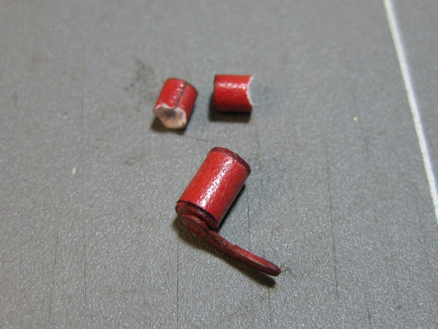
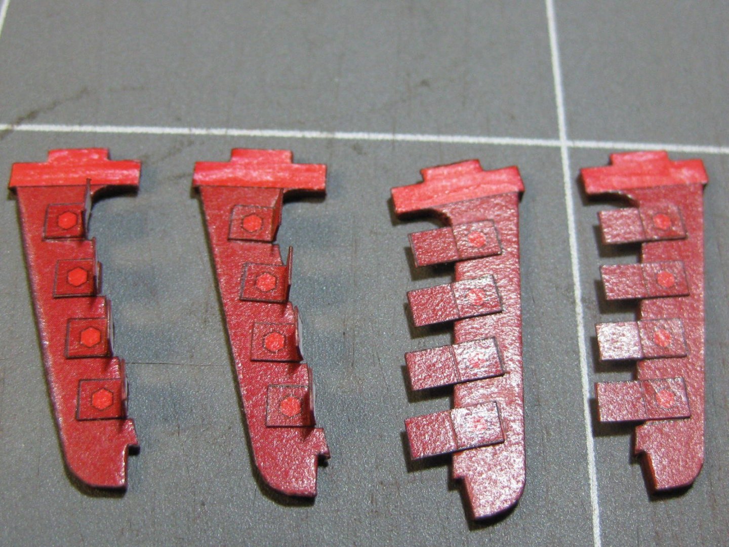
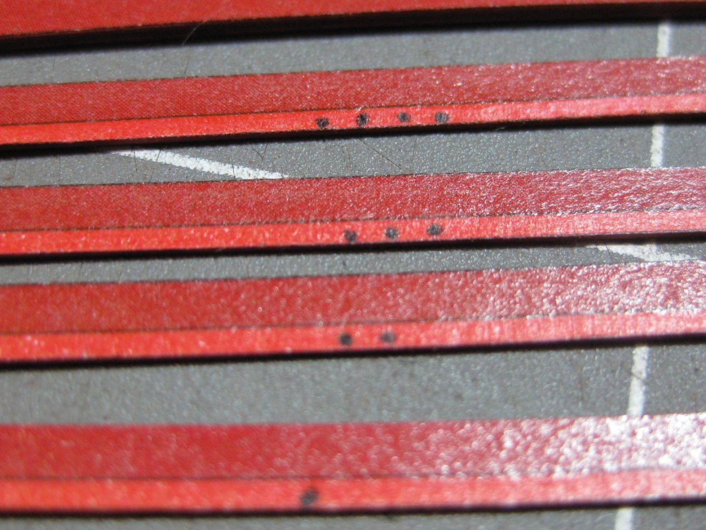
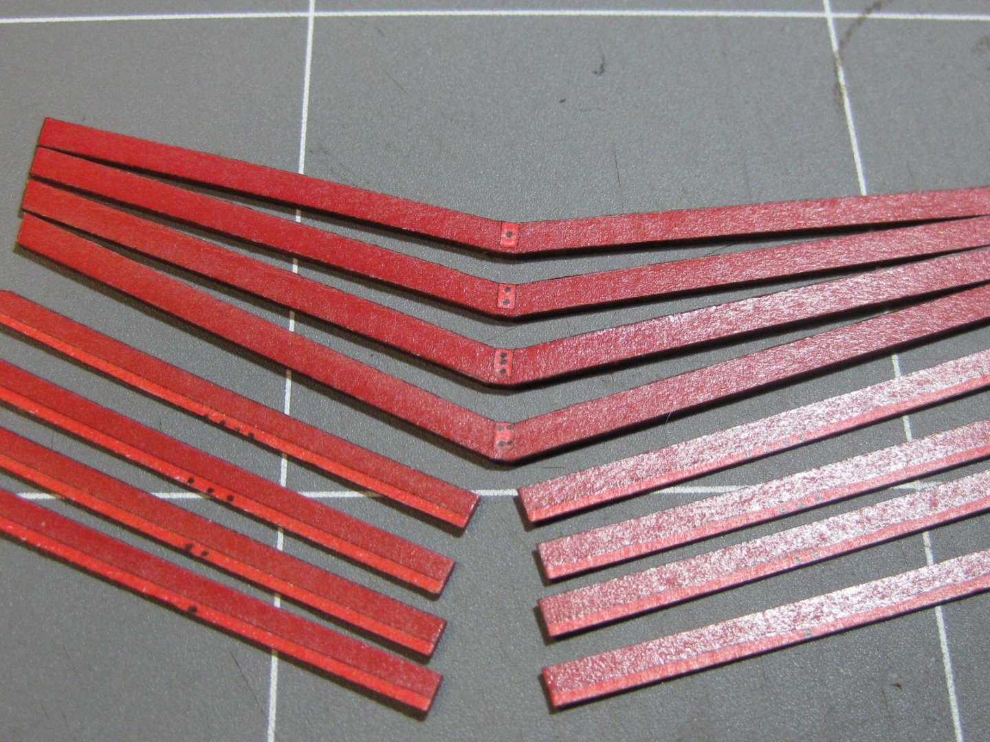
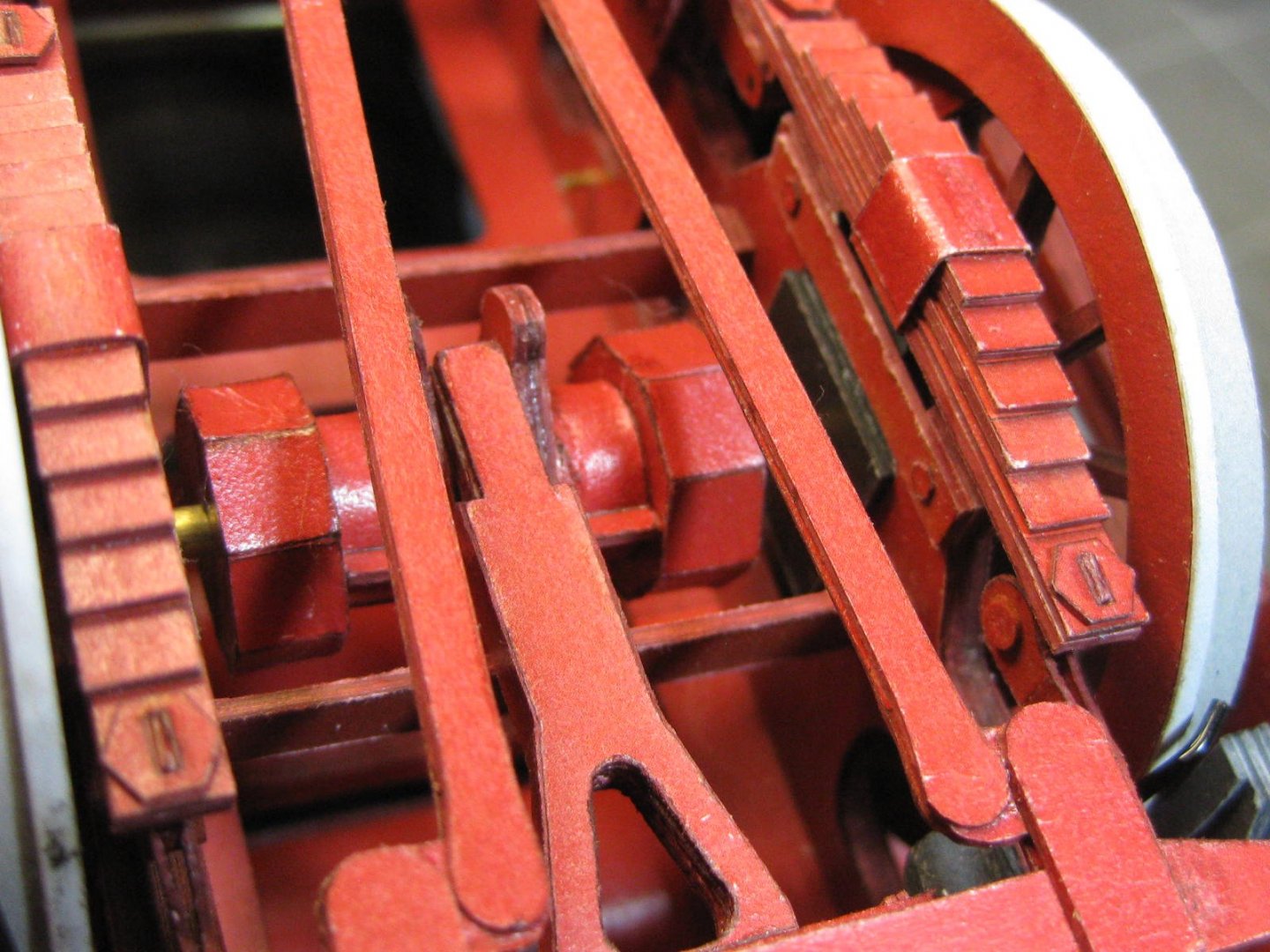
The two "cow-catchers" are the last major things to fit to the loco before it's finished. Here are the pics of them : The bars are all different angles and lengths, so I sorted them out and marked them before gluing them together : The brake hose fittings : All the front is now finished. Just a few rivets to re-glue and I can spray it with satin finish clear lacquer : Now to build the tracks for the base. Danny


- 150 replies
-
- 30
-

-
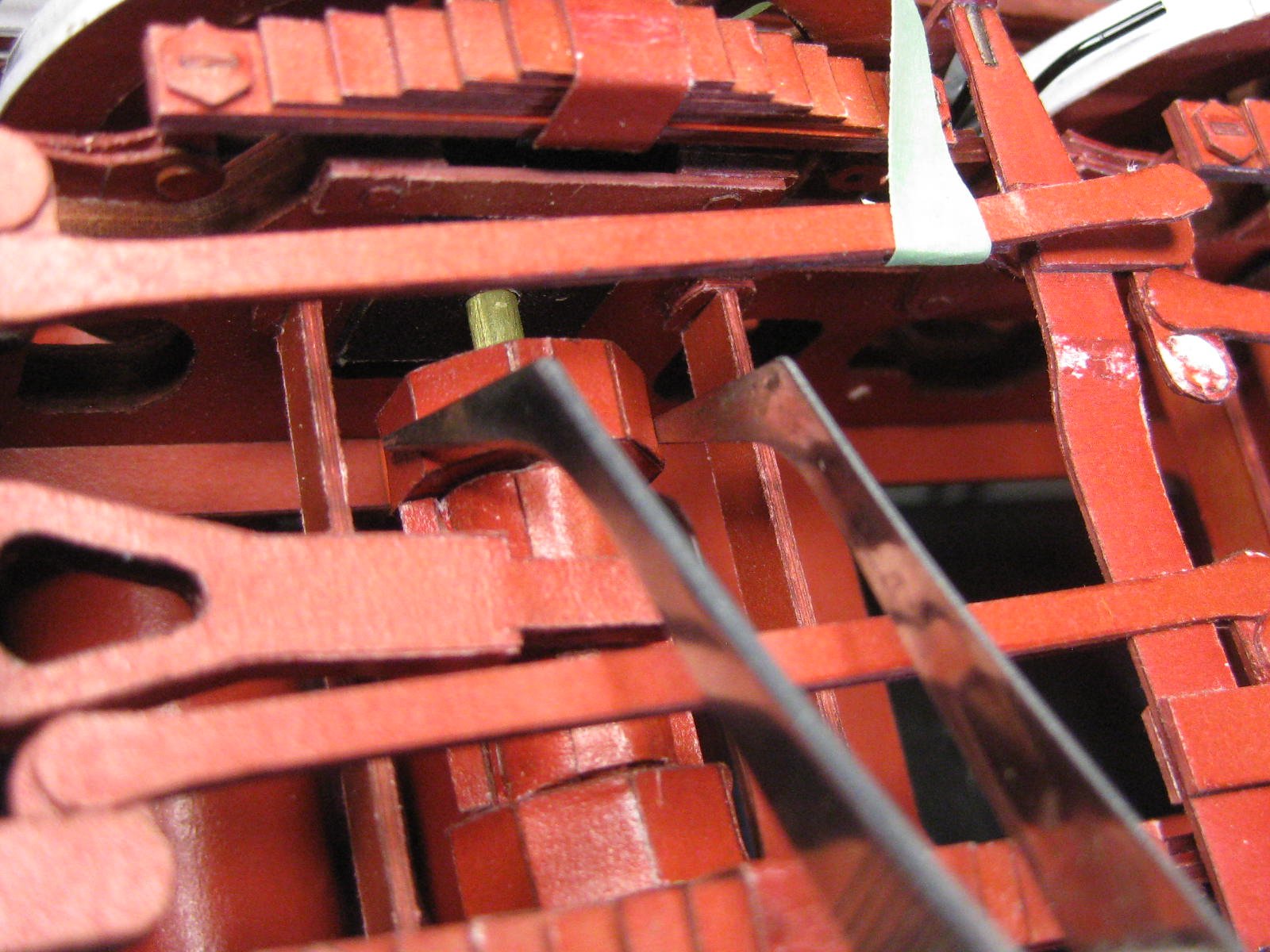
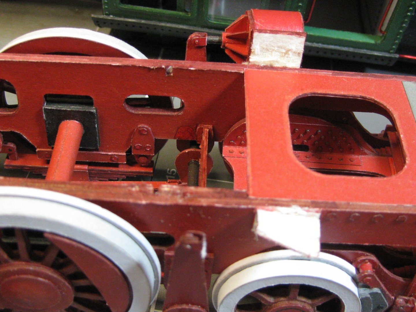
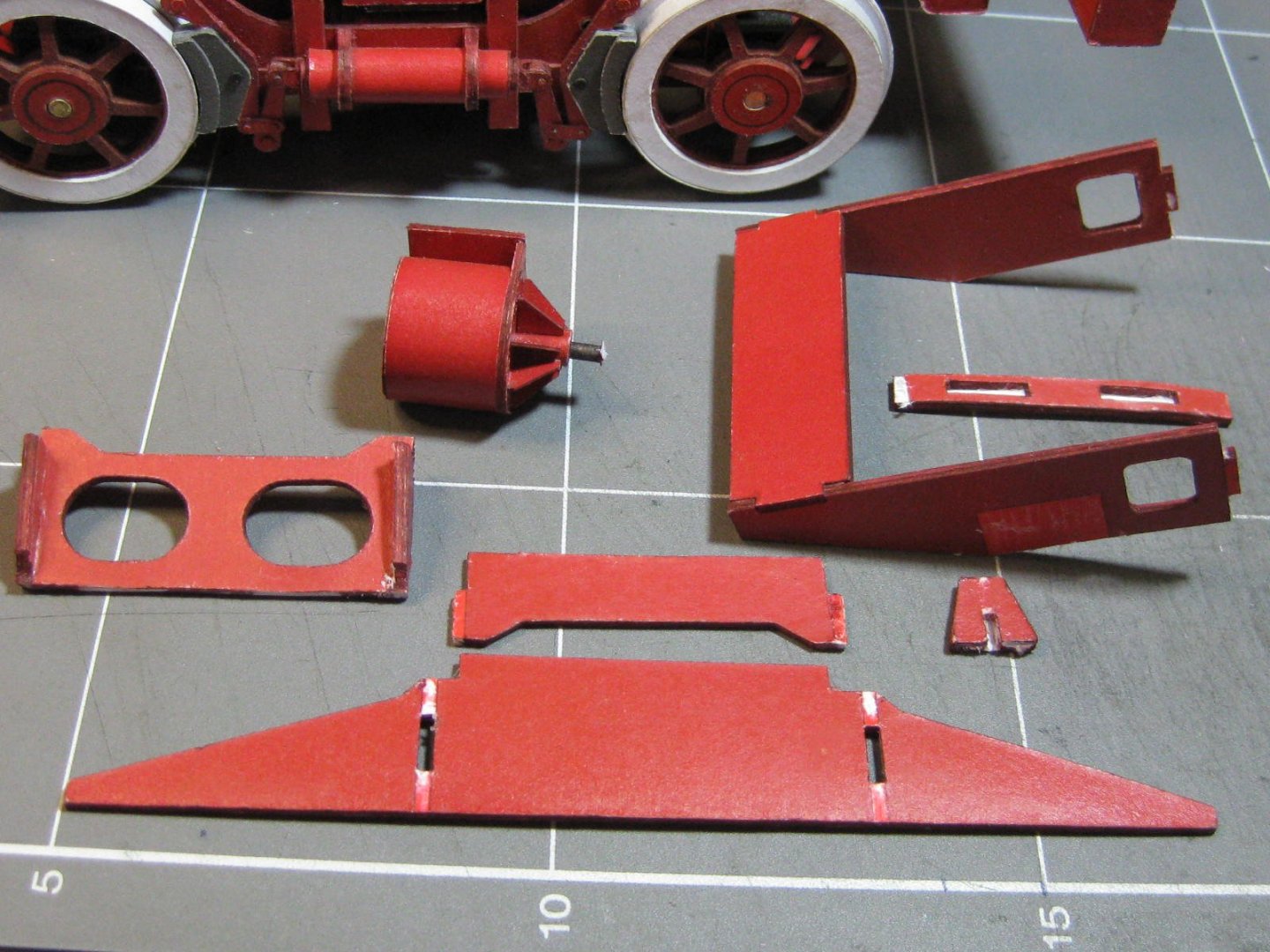
Yes I did . Thanks for the replies guys . Speaking of problems - I found a doozy. A long time ago, when I was building the front bogie, I made this drum-like piece which turns out to be part of the steering mechanism : This is the only diagram of this part - nothing in further diagrams to show how it fits, so at the time I put it aside with the thought it may become more obvious later in the build. Unfortunately it should have been fitted much earlier before I'd fitted the main axles and wheels, as the front axle is supposed to go through the middle of it. How to fix the problem? I approached the dilemma with the thought in mind of leaving it off altogether if I couldn't work out a solution. There was no way I could easily remove the axle as it was attached to the wheels with CA glue - impossible to remove without causing major damage to already fitted parts. In addition the crank and a few other parts would also have to come off. I came up with the idea of splitting the drum in half and slipping it over the axle. If the idea didn't work then I'd have had to leave it off, but at least I wouldn't have damaged anything else. The sequence below shows how I did it. First pic is of the axle it had to fit around and the seemingly impossible place it was in : Removing the two hexagonal ends was fairly easy, as I hadn't scraped off the clear coat. A single-edge razor blade did the trick : After cleaning everything up the three pieces went on relatively easily : All done : Danny

- 150 replies
-
- 22
-
-
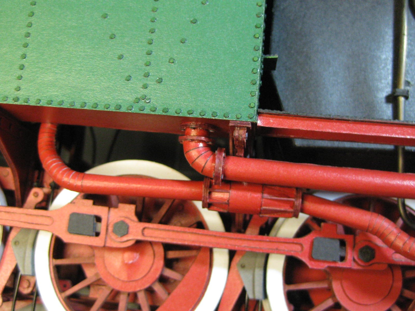
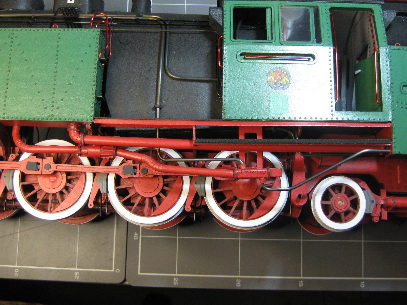
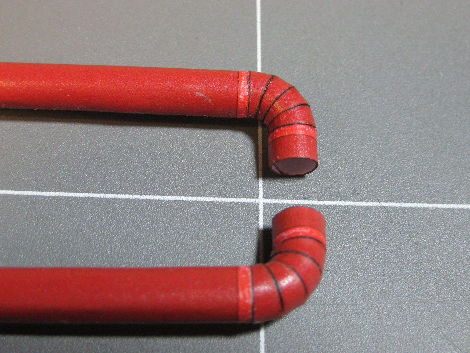
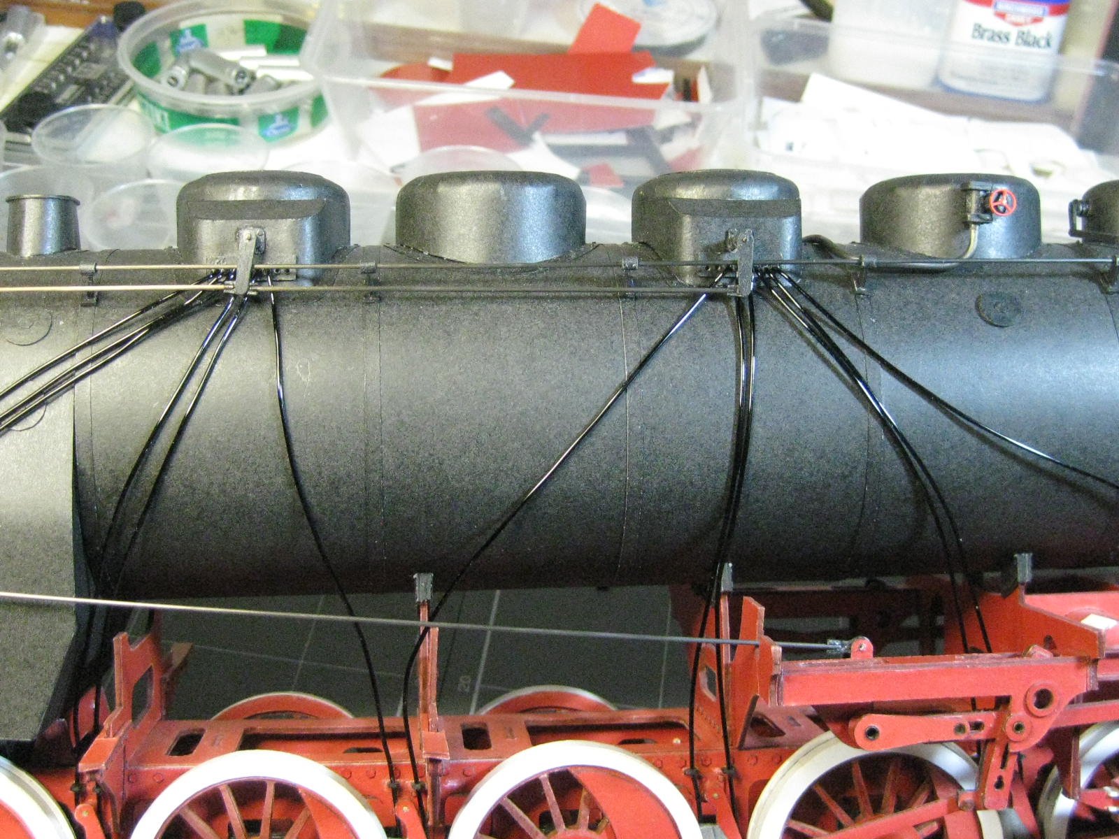
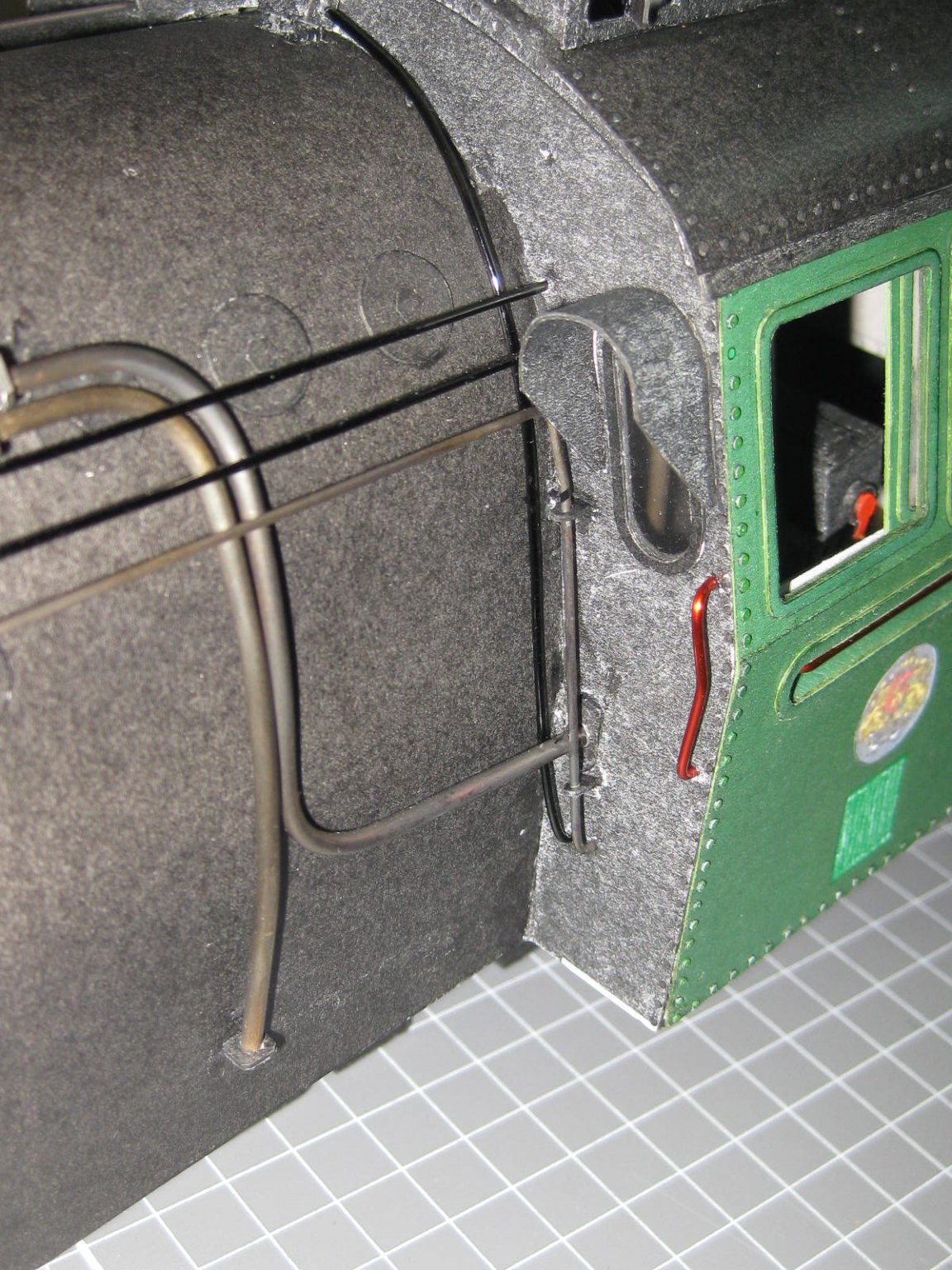
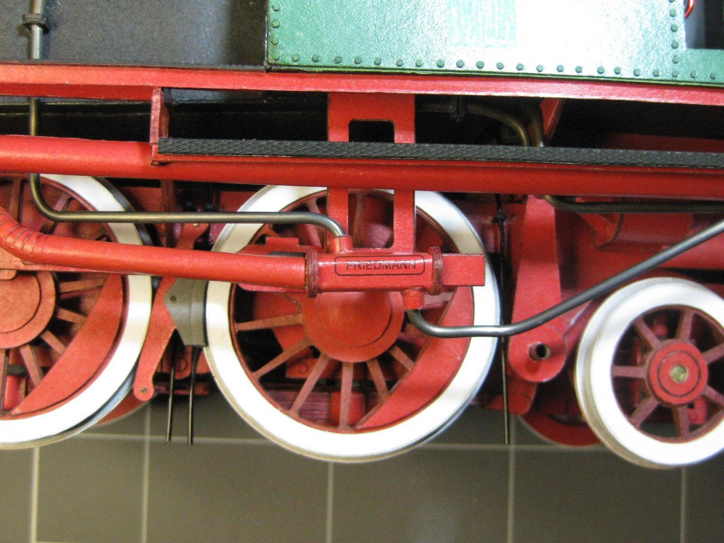
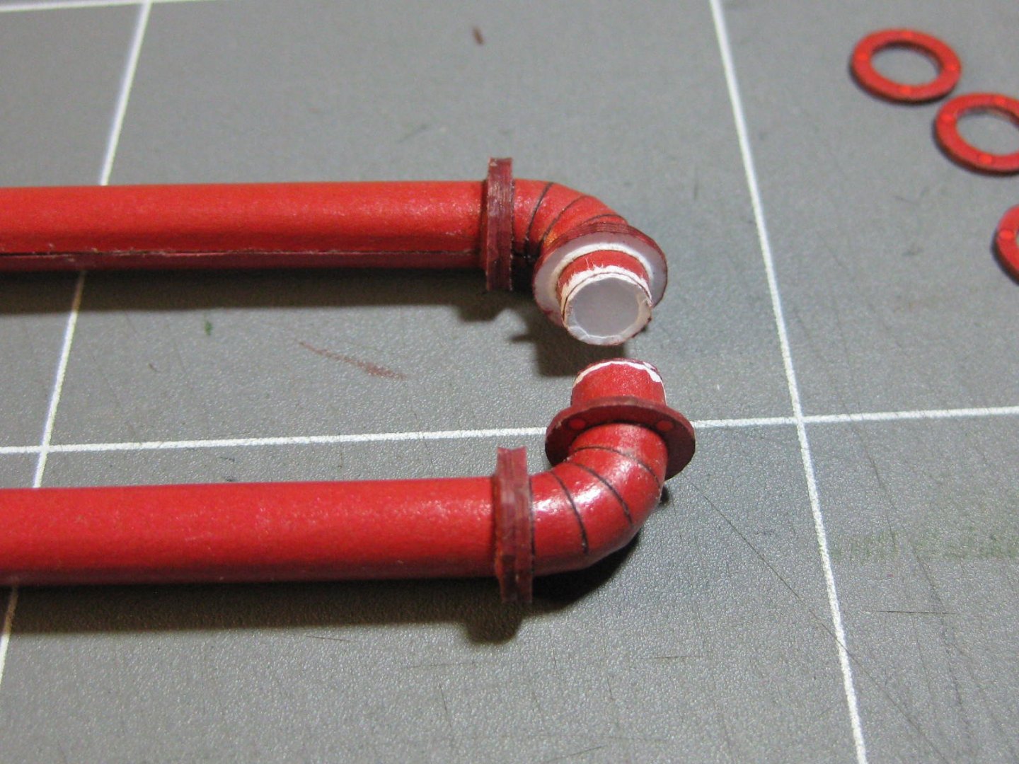
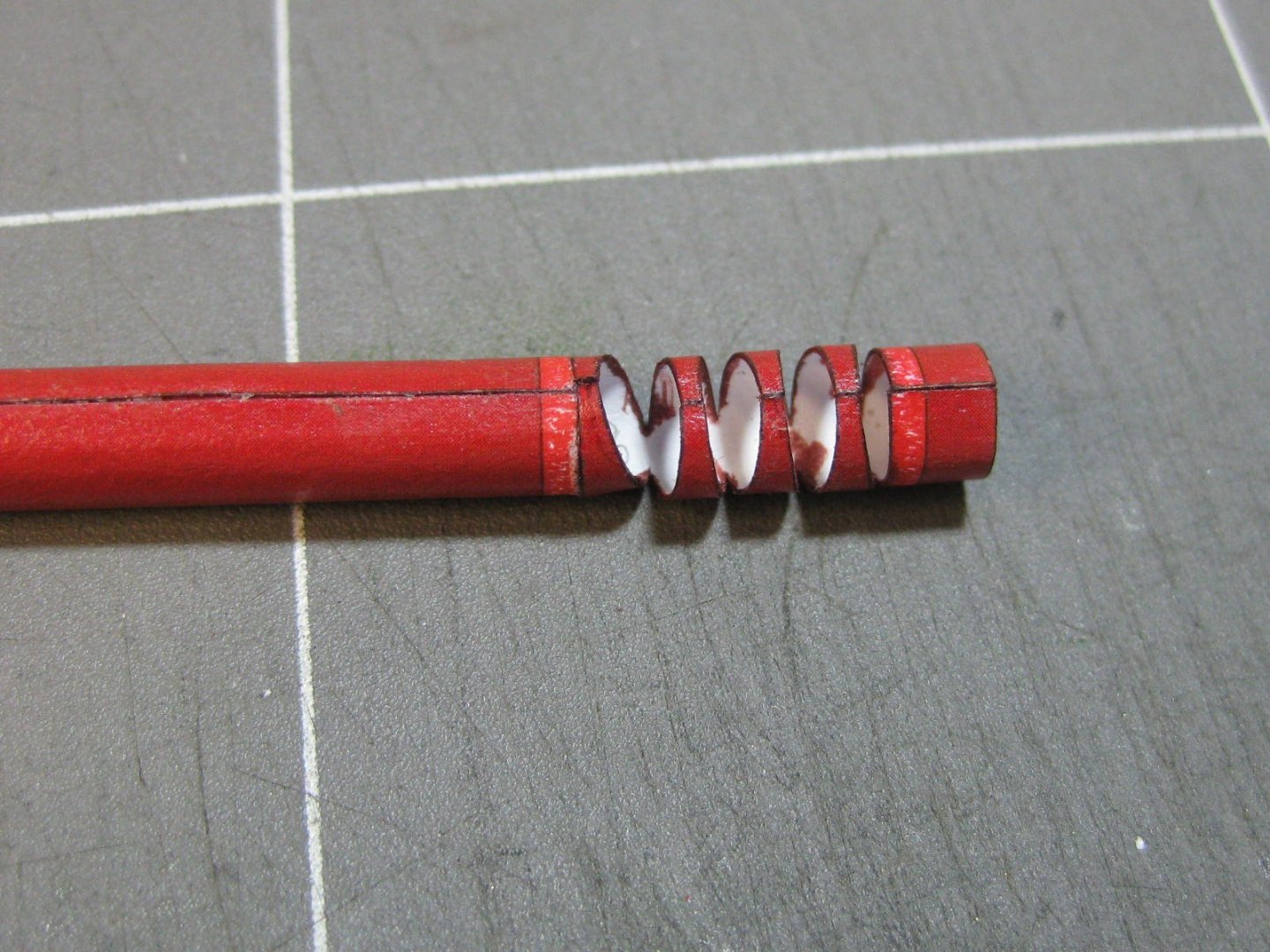
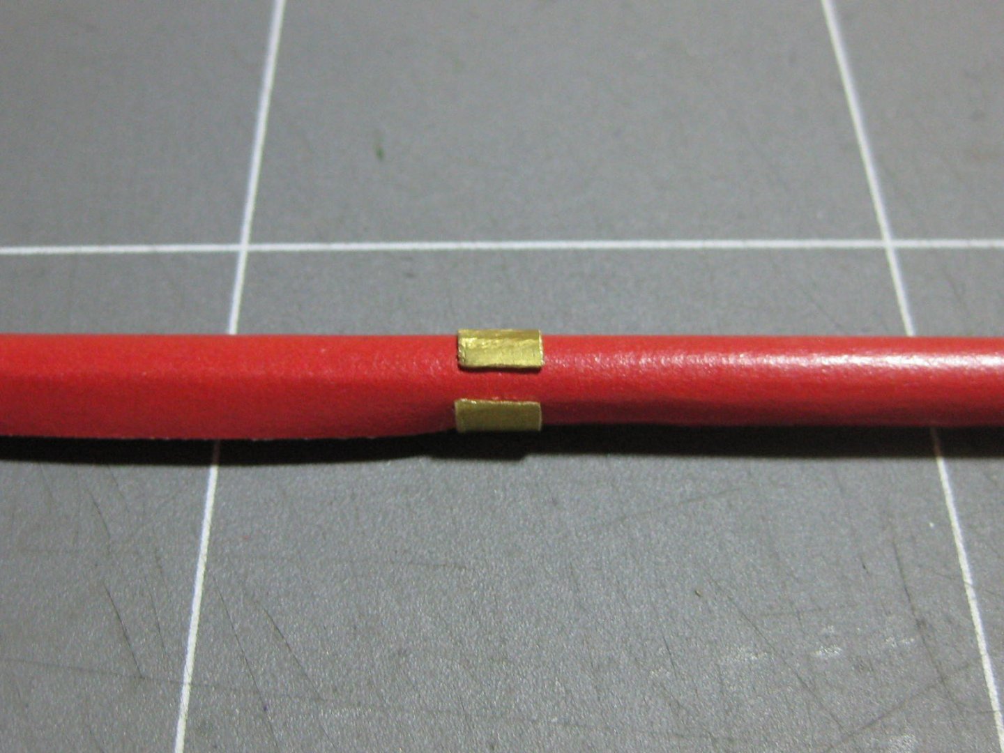
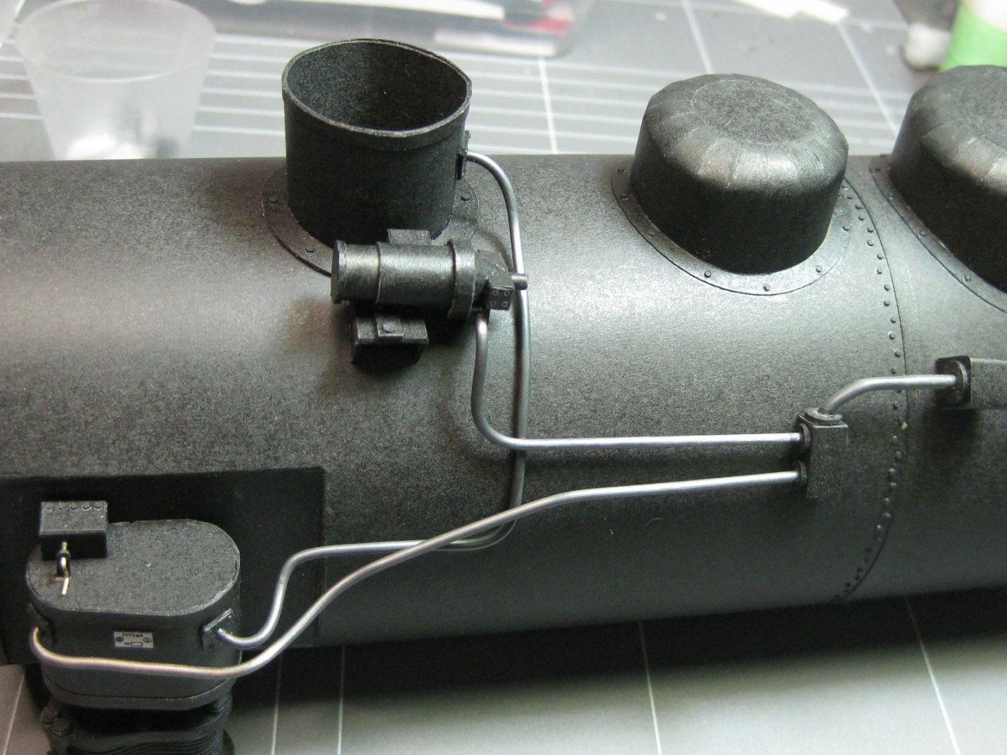
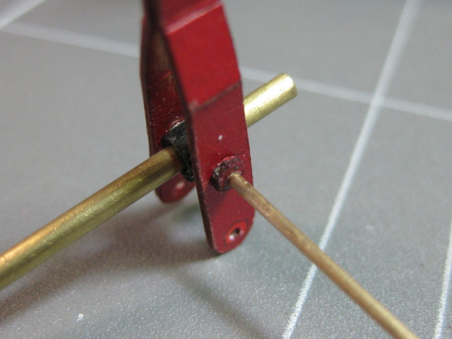
There's only 1840 rivets in these two assemblies. There are a LOT more in the boilers, cab, coal bunker etc . Around 4,000 in the whole loco. Thanks for the insights Cap'n Mac and Ken . I've discovered a new way to roll long pipes. I usually use a long piece of tubing to do the whole pipe in one go, but the tubing I have isn't the right inside diameter (missed out by about 0.3mm ). So I cut a short piece of the slightly undersize brass tube, cut a slot in it lengthwise to open it up and cleaned it up with a fine diamond-coated file. Then I used a long piece of tubing to support the inside and used the outer one like a clamp to squeeze the card tube together while I glued about 15mm in one go. Once it dried sufficiently I slid the tubing along and repeated the process - it took about 10 minutes to do a 100mm pipe and it turned out perfectly : The ends of some pipes had bends in them : Also flanges : The water piping down the left side of the loco - the right side doesn't have any, instead there is a "balance pipe" between the two tanks that keep the left side one full : I'm guessing this is the water pump ? It needs a little re-aligning which I can do when all the glue has dried : Danny


- 150 replies
-
- 24
-
-
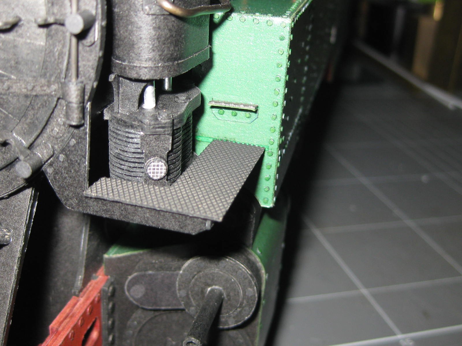
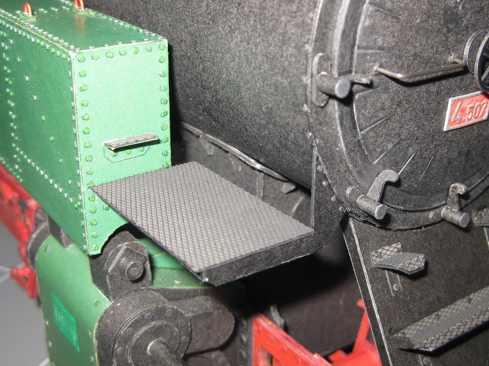
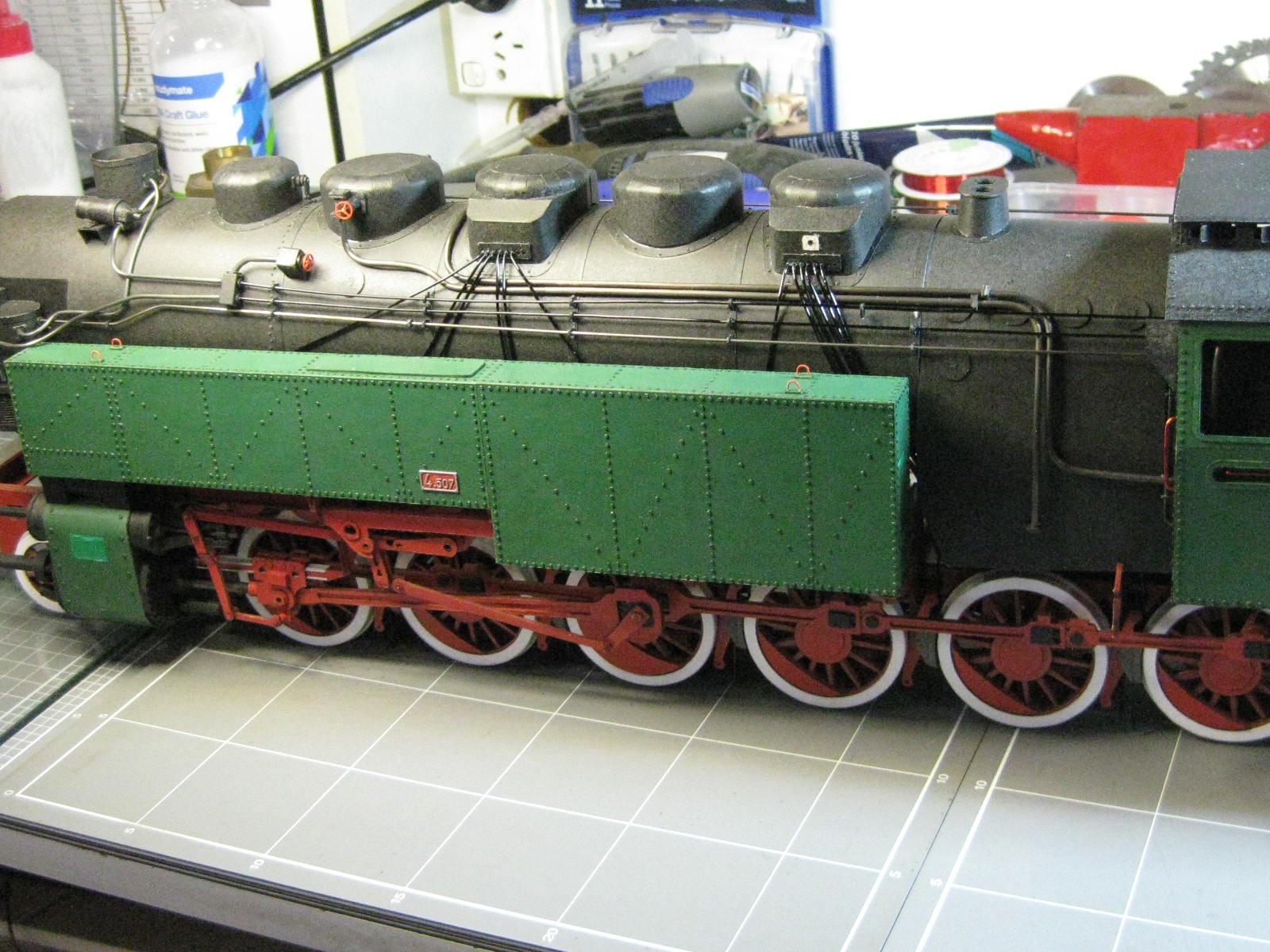
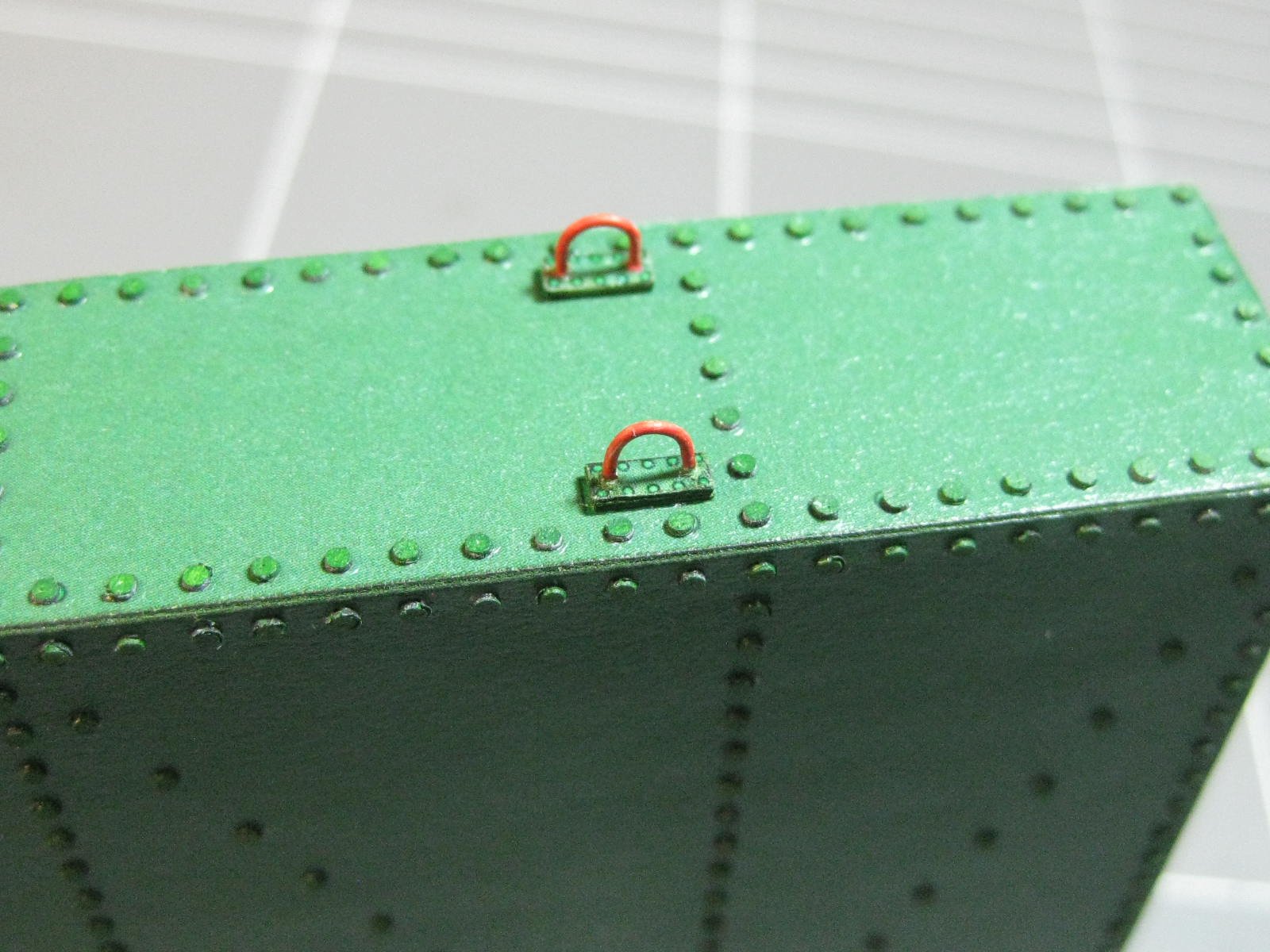
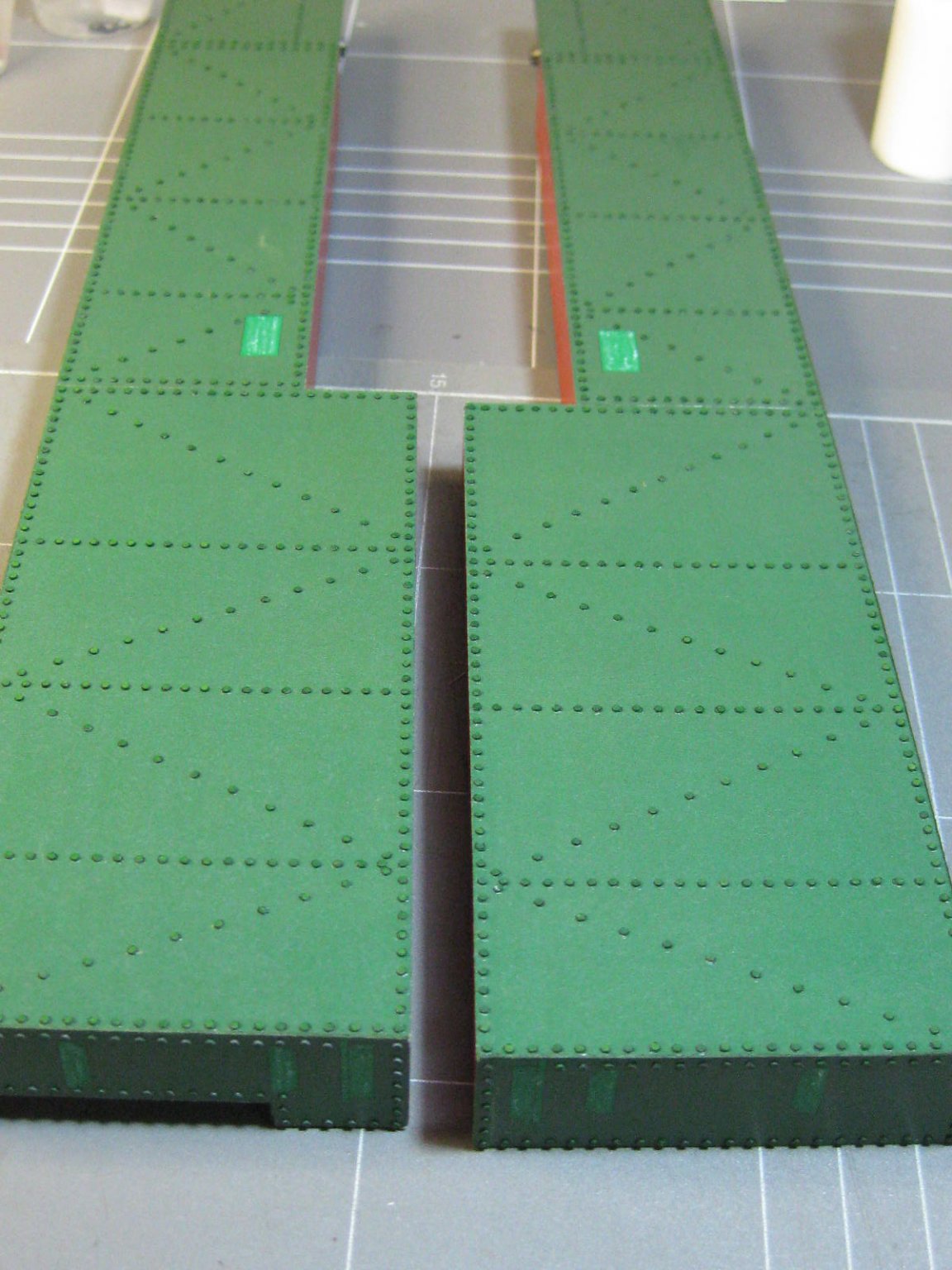
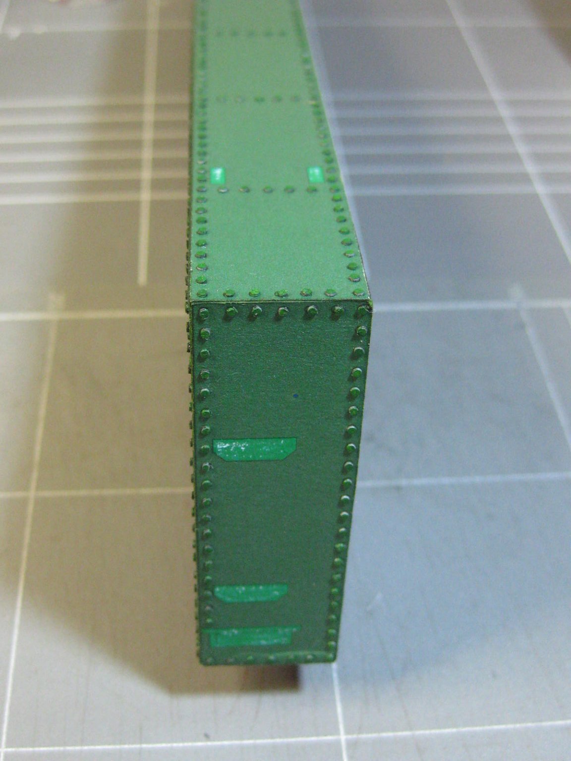
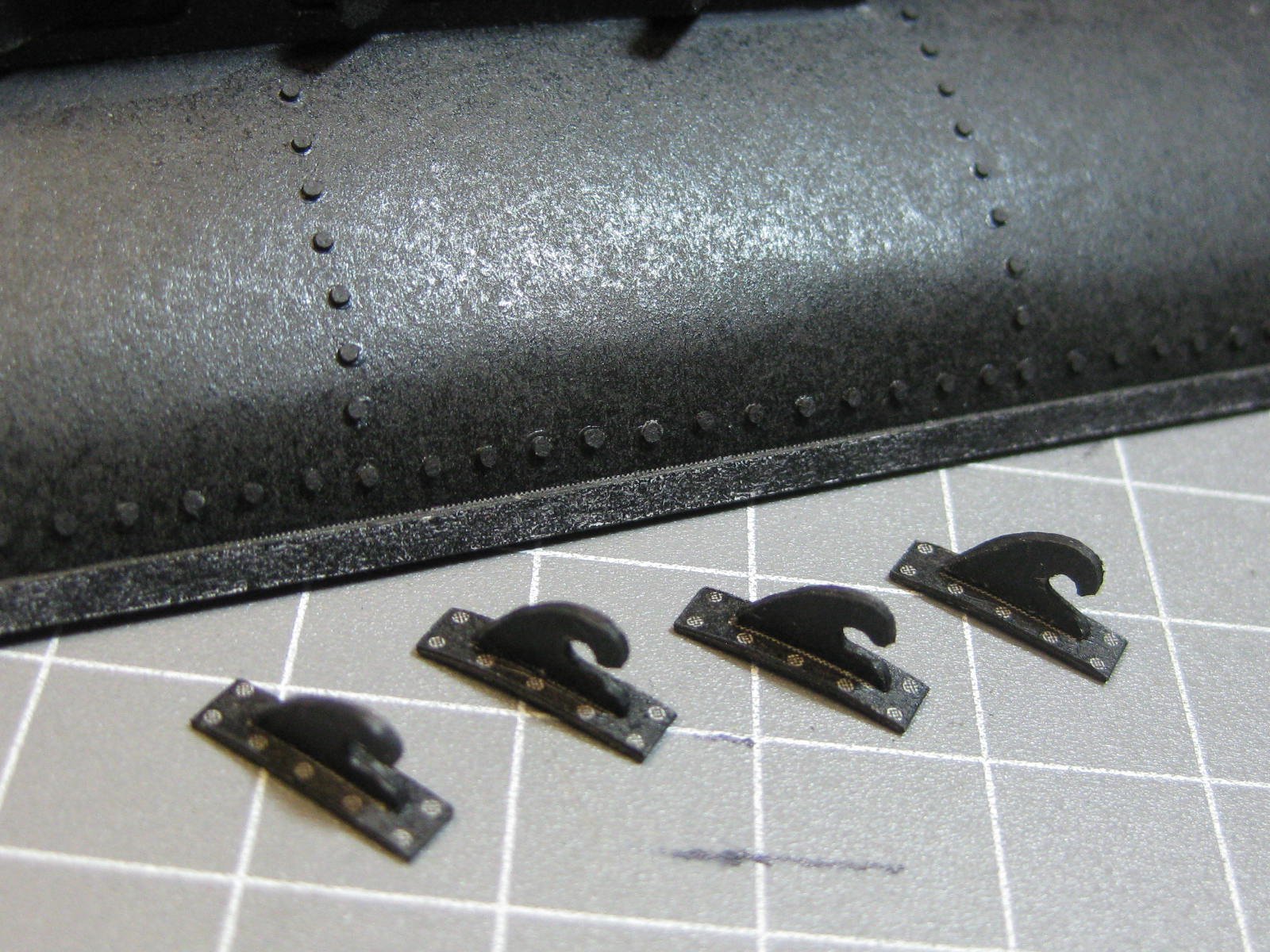
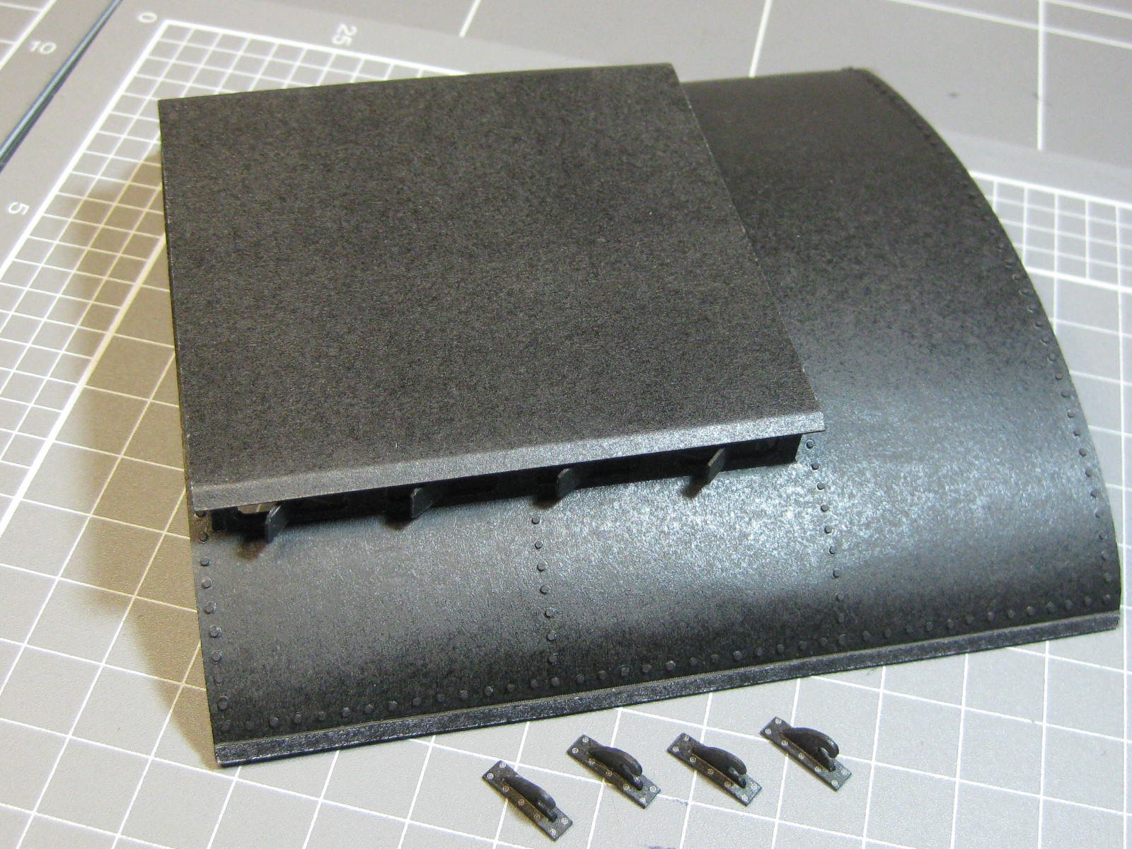
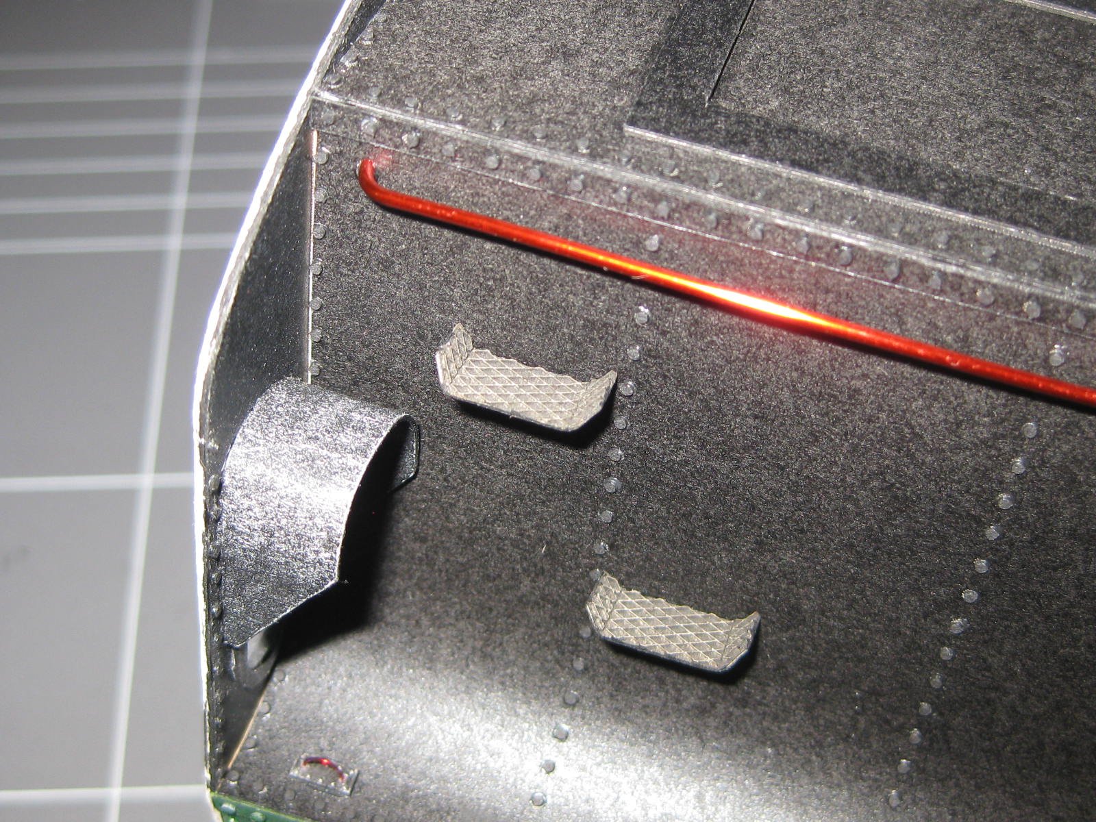
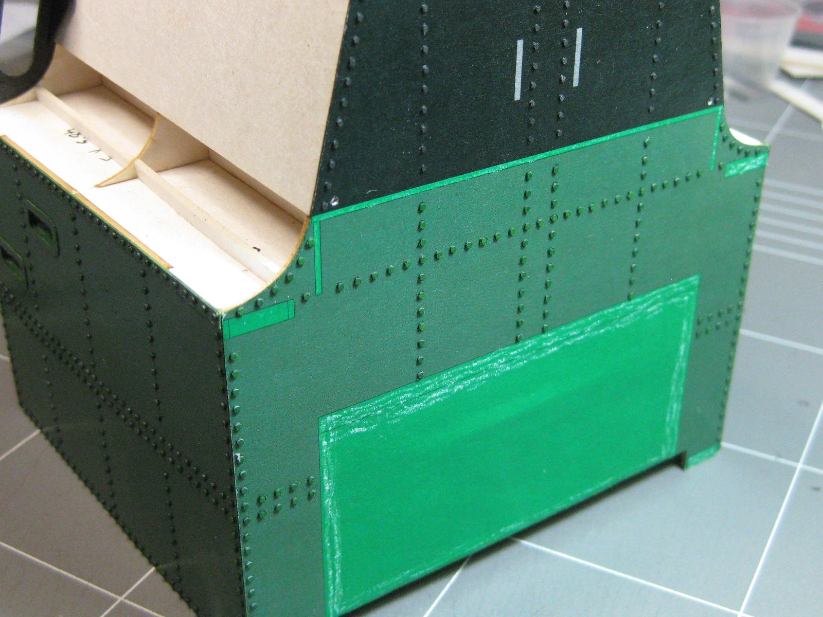
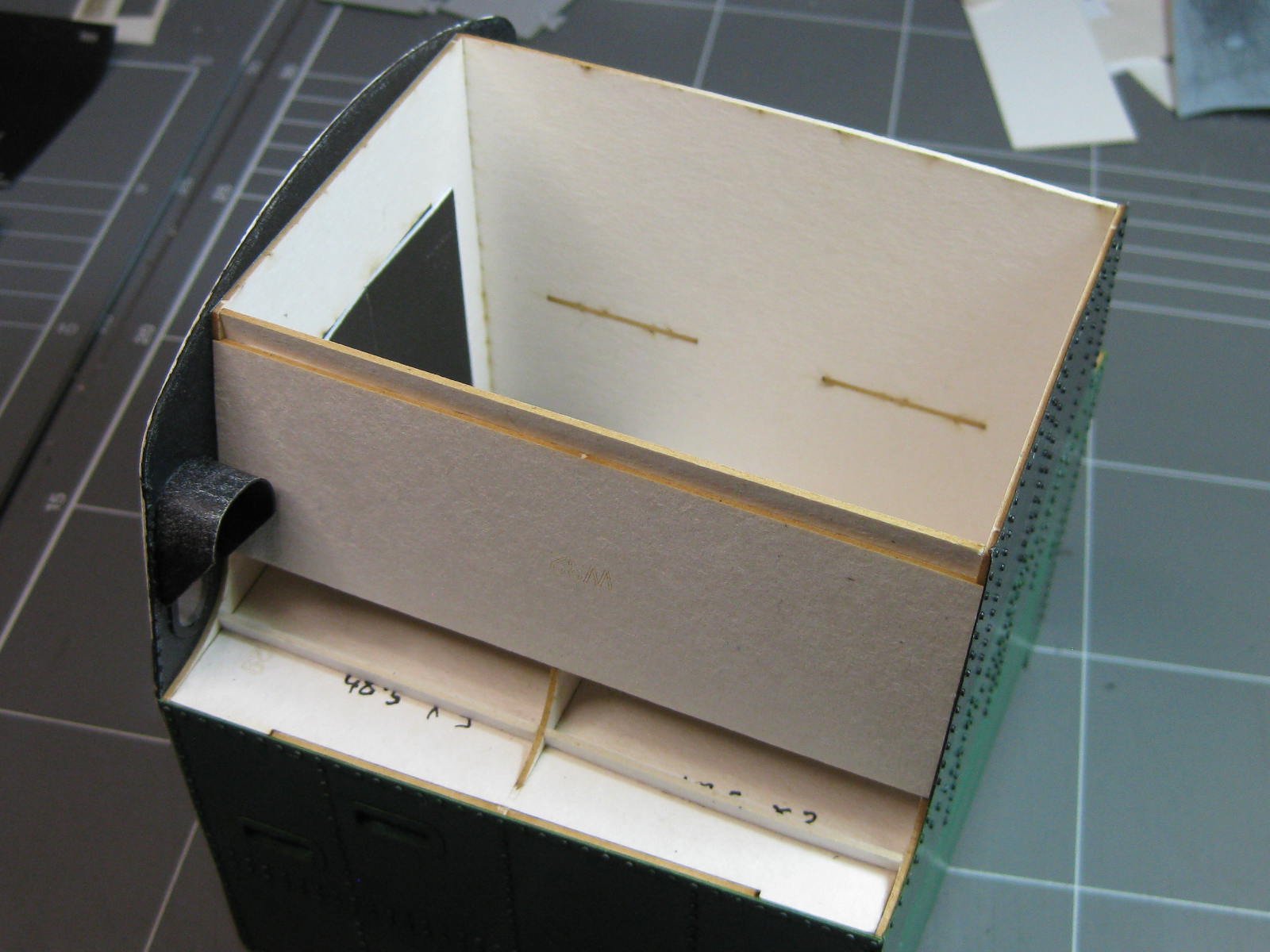
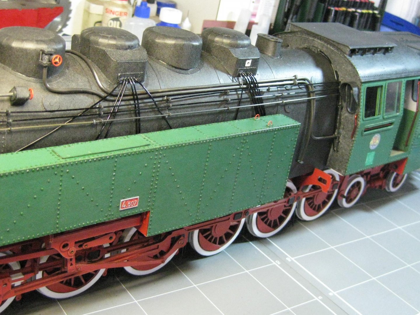
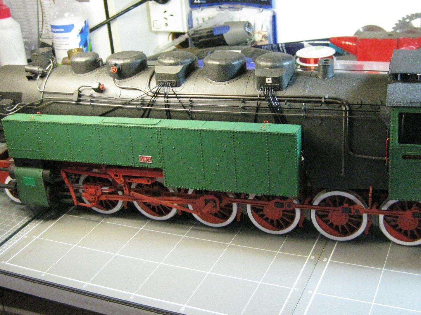
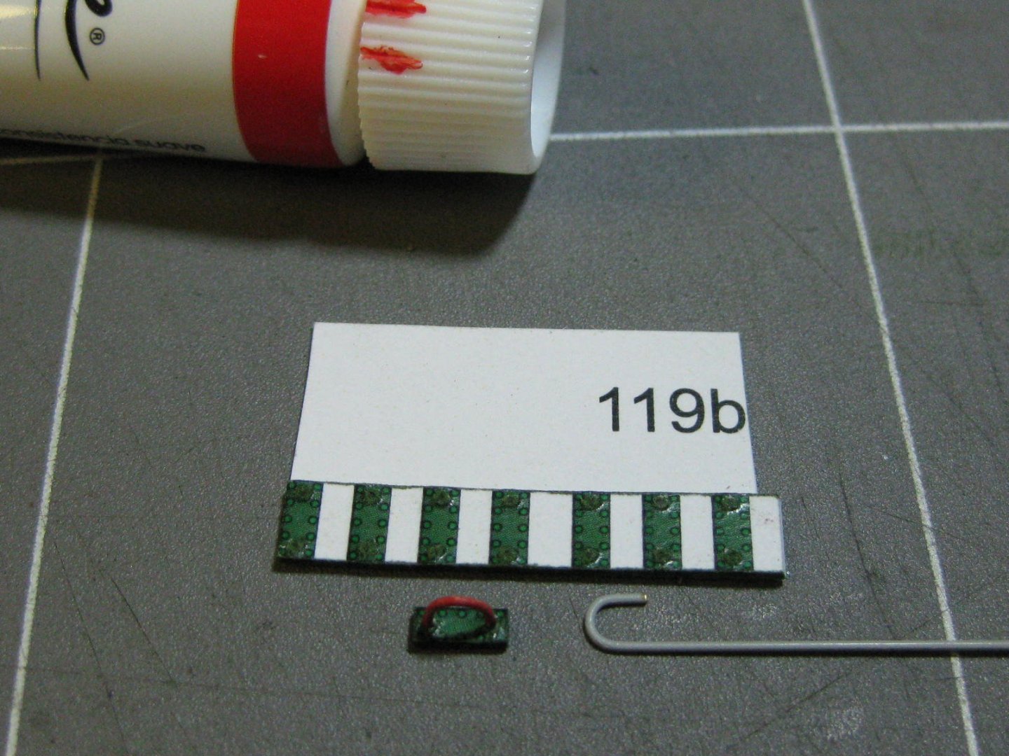
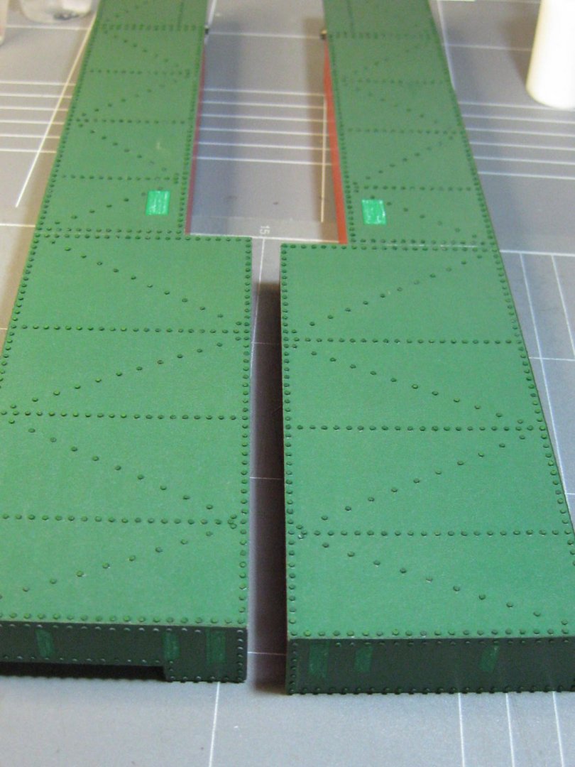
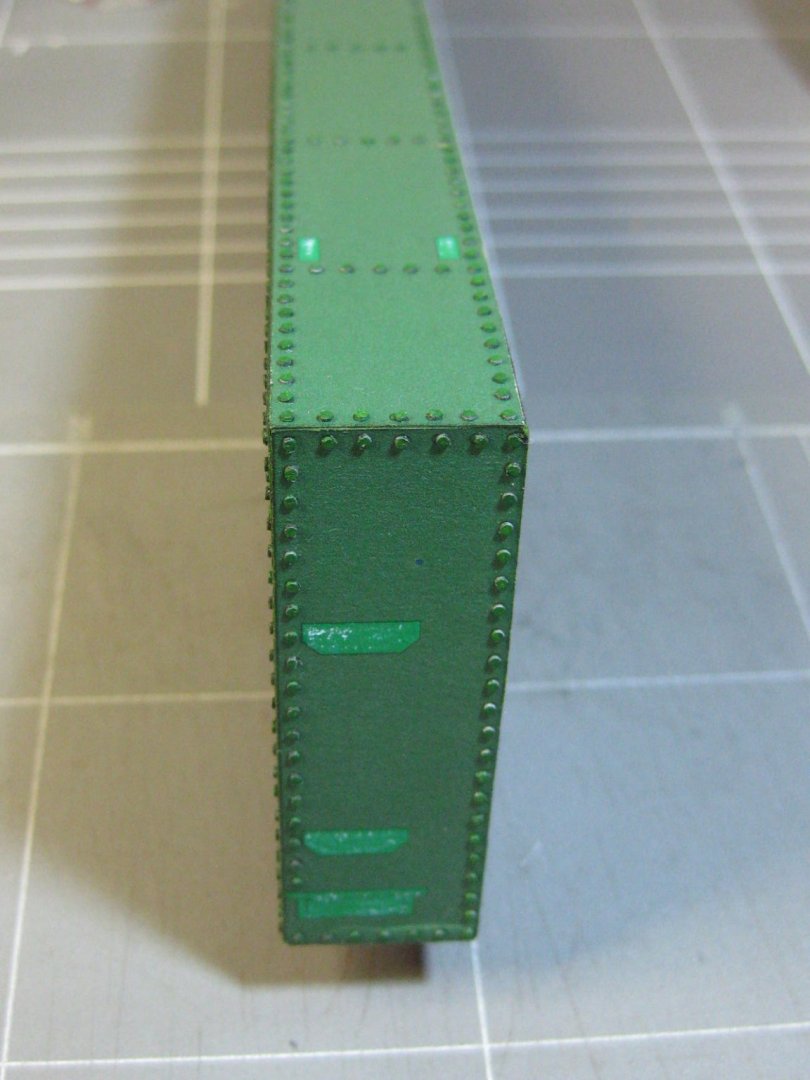
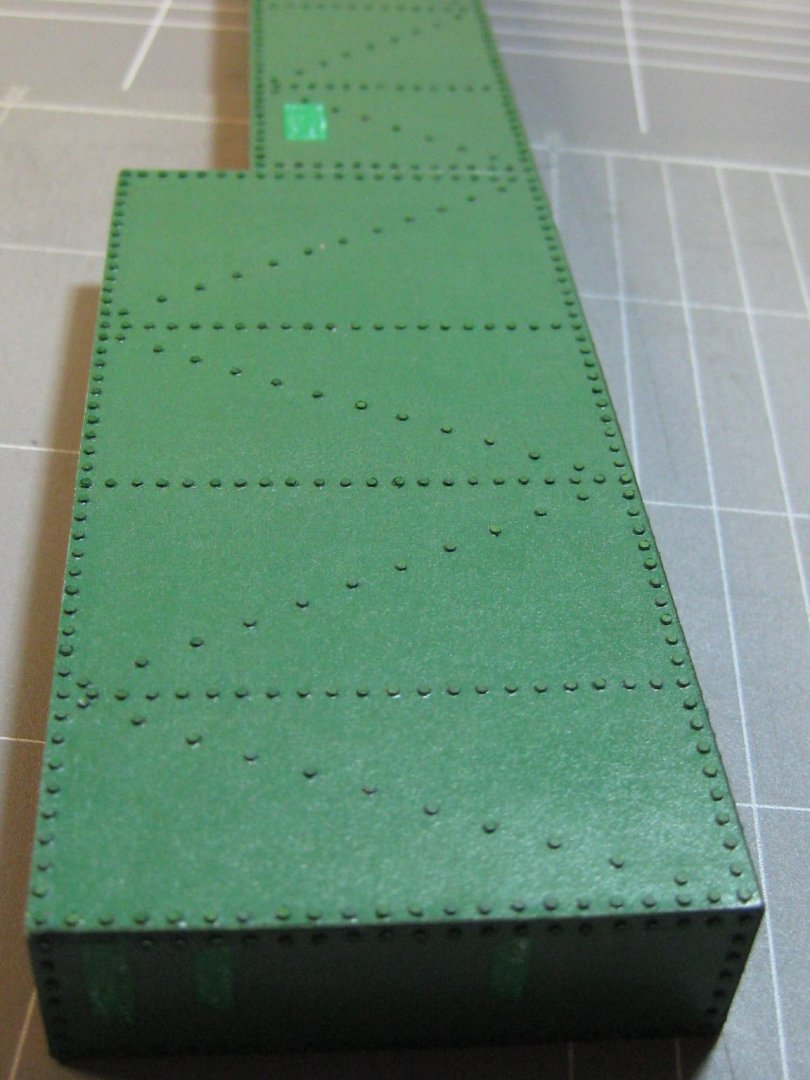
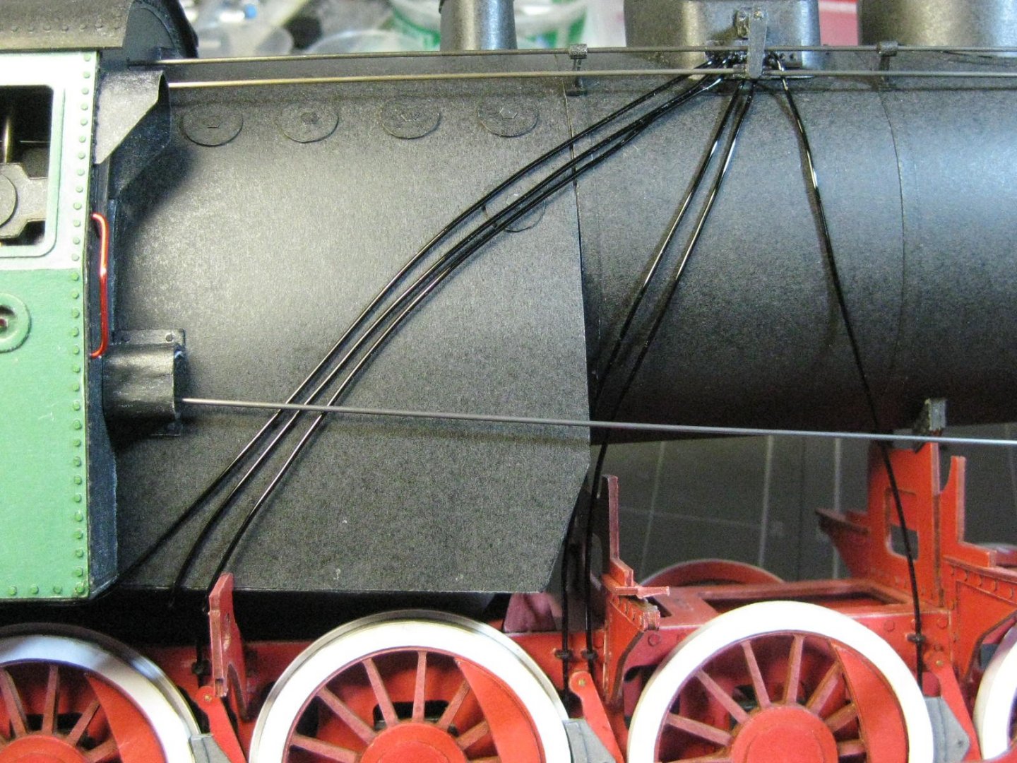
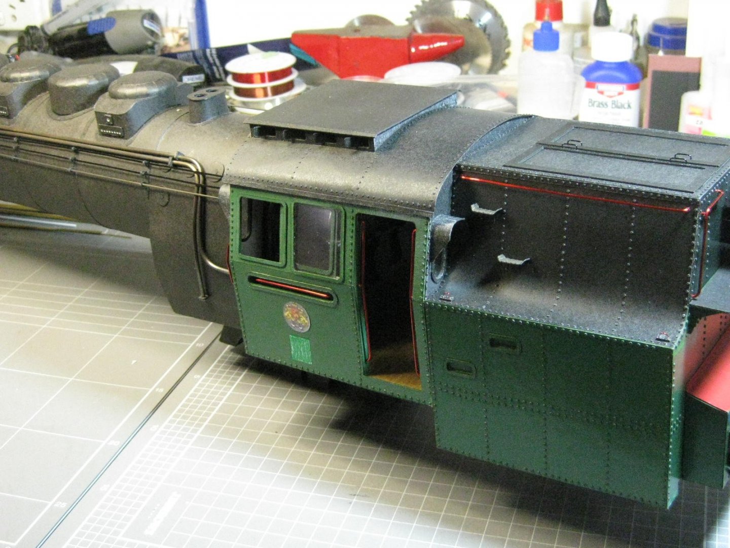
There was a mistake with the kit much earlier in the build, which means that the cab/boiler/bunker won't go on properly. The section below is 1.5mm too deep (I cut it right ) so I had to remove it using a combination of scalpel and Isocol and fixed the problem : It took me a couple of days to fit the sand pipes, all 24 of them. I still need to do the very bottoms of them, which I'll do a bit later in the build : I made up some brackets to anchor the pipes above the wheels and keep them in position : A couple more views of the pipes : The last major sub-assemblies are the two water tanks alongside the boilers. Here's one of them during assembly of the framework : After skinning the water tanks there came the job of gluing on the rivets - all 1,840 of them. I've had problems with the rivets coming off on the cab and coal bunker due to the clear coat on the kit, but I think I found the solution after a bit of experimenting. Isopropyl Alcohol removes the clear coat without harming the printed finish : Some lifting lugs. I'm going to re-do the four I did earlier on the coal bunker to match these as the others look too thin (0.3mm as compared to 0.5mm wire and a different shade of red as well) : One of the tanks sitting in place. More work needs doing to it before I can do the final fitting : Danny


- 150 replies
-
- 18
-
-
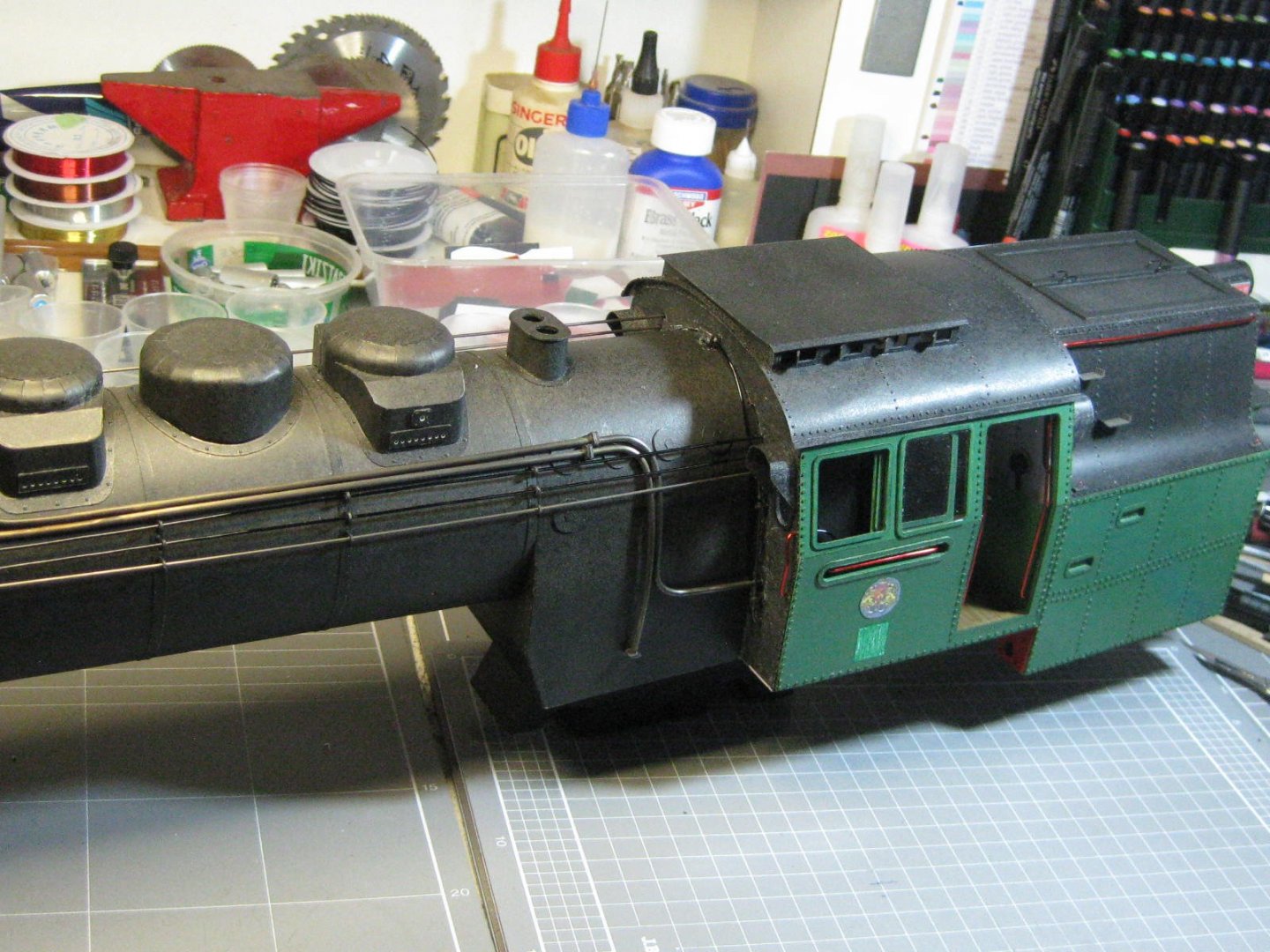
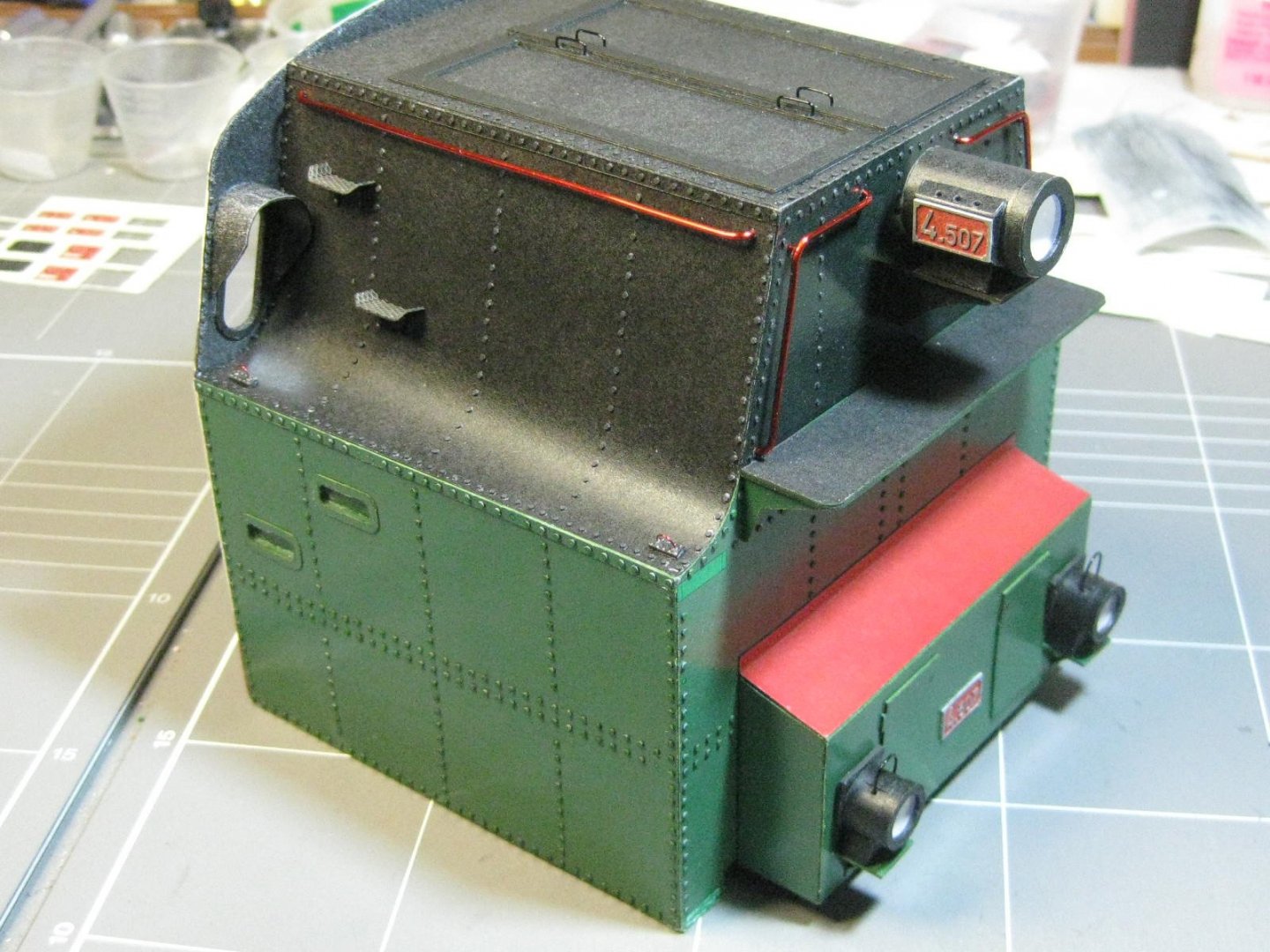
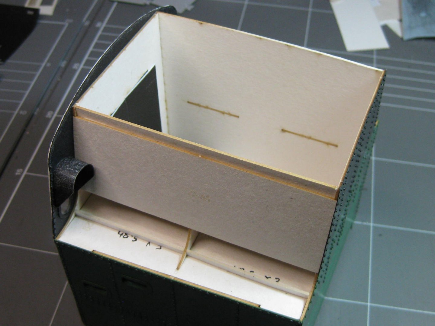
The roof is lined on the inside as well. I pre-formed it before gluing it on. There are 8 air vents in the top section : The coal bunker has now been fitted to the cab, and the cab roof as well. It sounds easy when you say it quickly : Next job will be to fit the entire boiler/cab/coal bunker unit to the chassis. Danny


- 150 replies
-
- 21
-
-
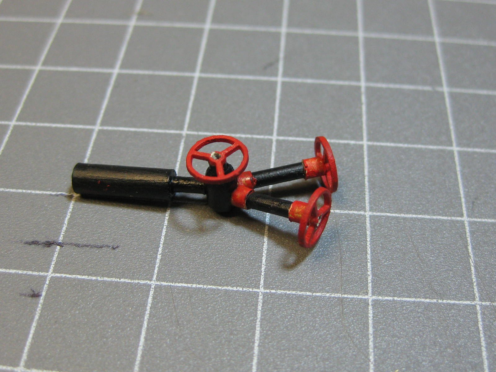
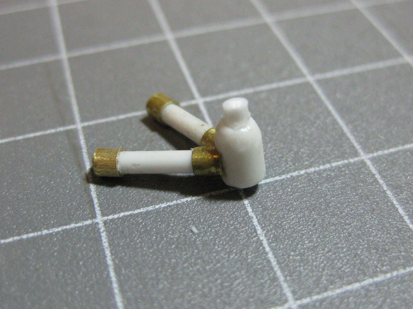
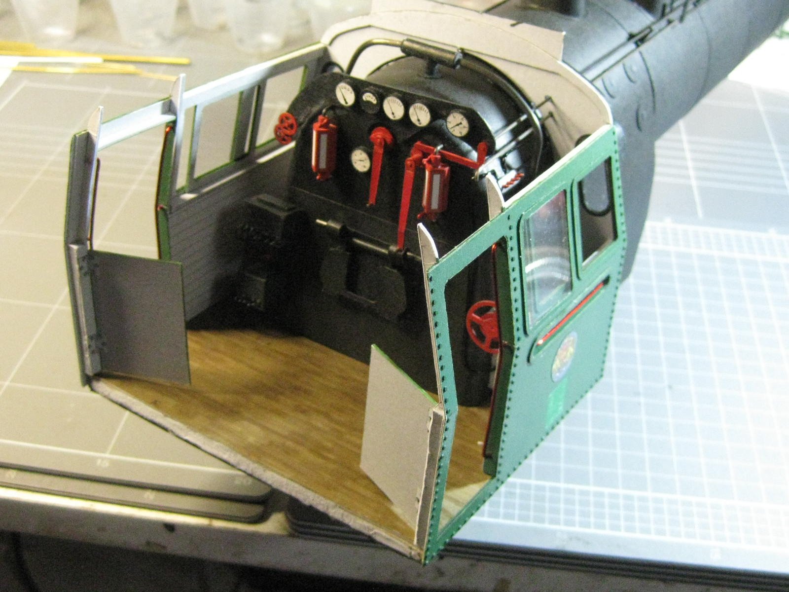
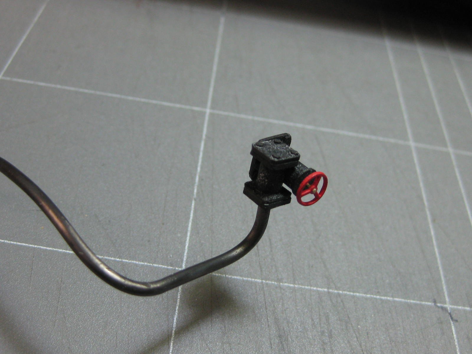
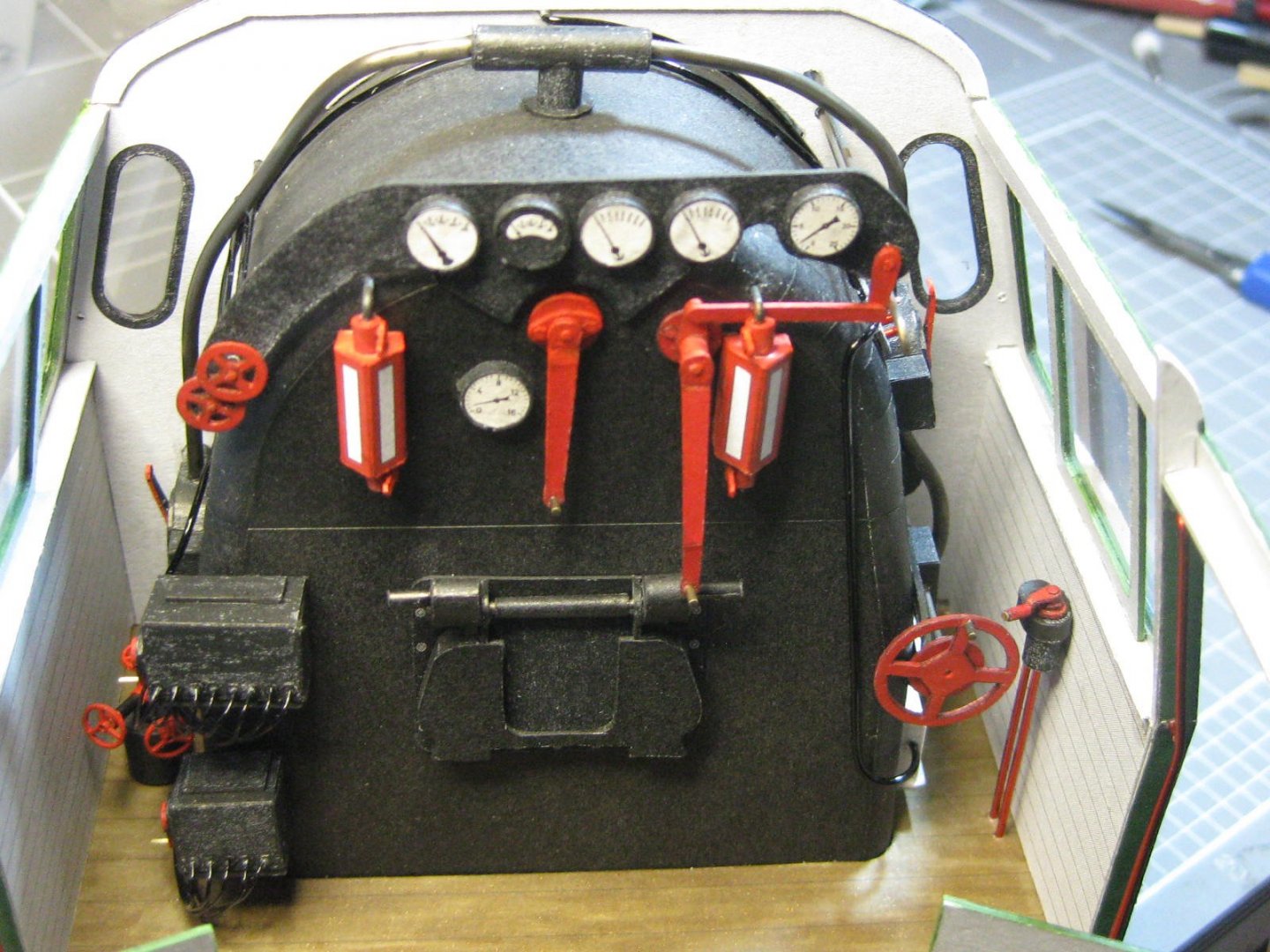
Thanks for the comments guys, and also to all those who "Liked" my posts . I've done all the cab detailing that I'm going to do. A few of these parts will be a bit difficult to see when the cab is completed, but the pics are proof that they are in there . This triple valve is made from brass tubing and styrene rod. The handwheels are laser-cut paper : Two scratchbuilt switch panels : Now I could fit the sides. The fit was perfect : Some final pics of the cab interior before things get harder to see : Danny


- 150 replies
-
- 17
-
-
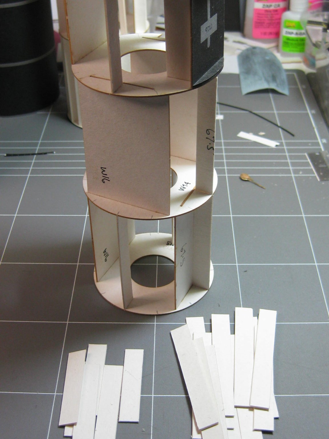
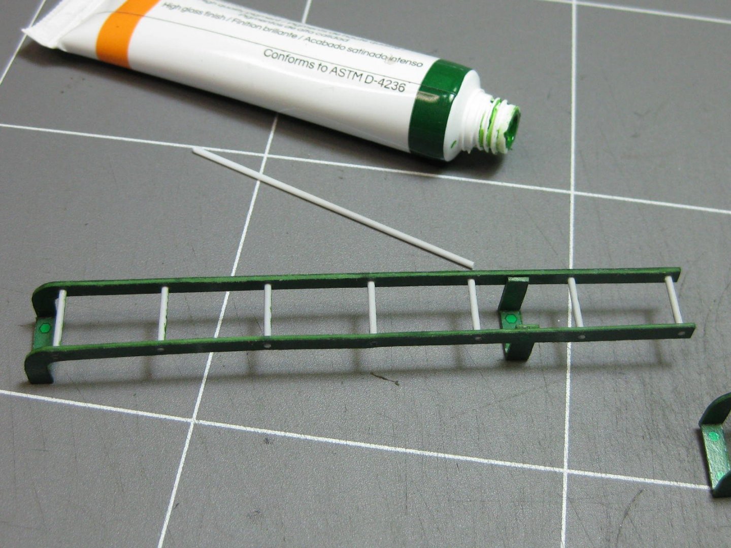
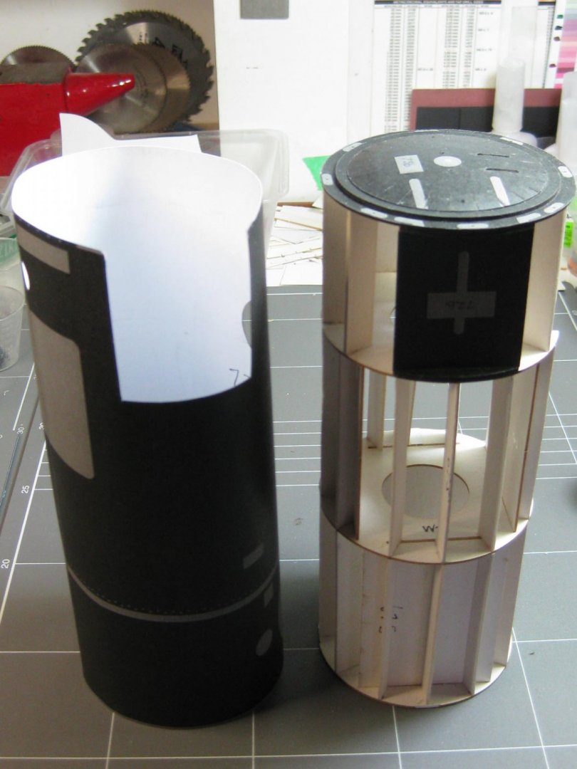
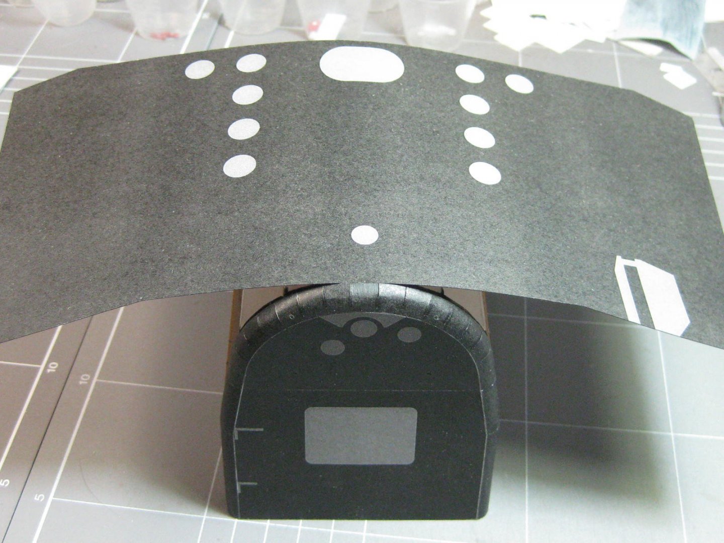
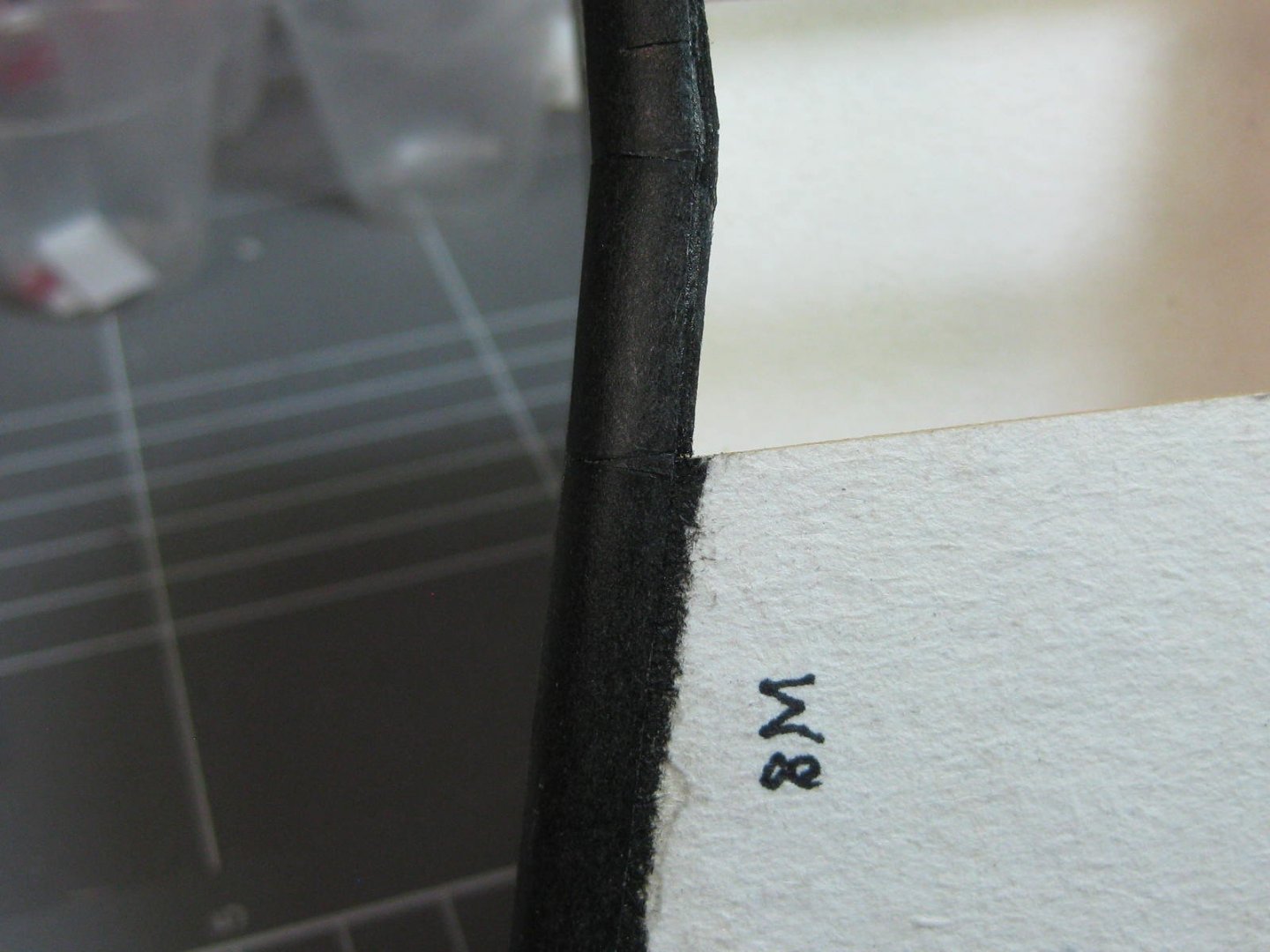
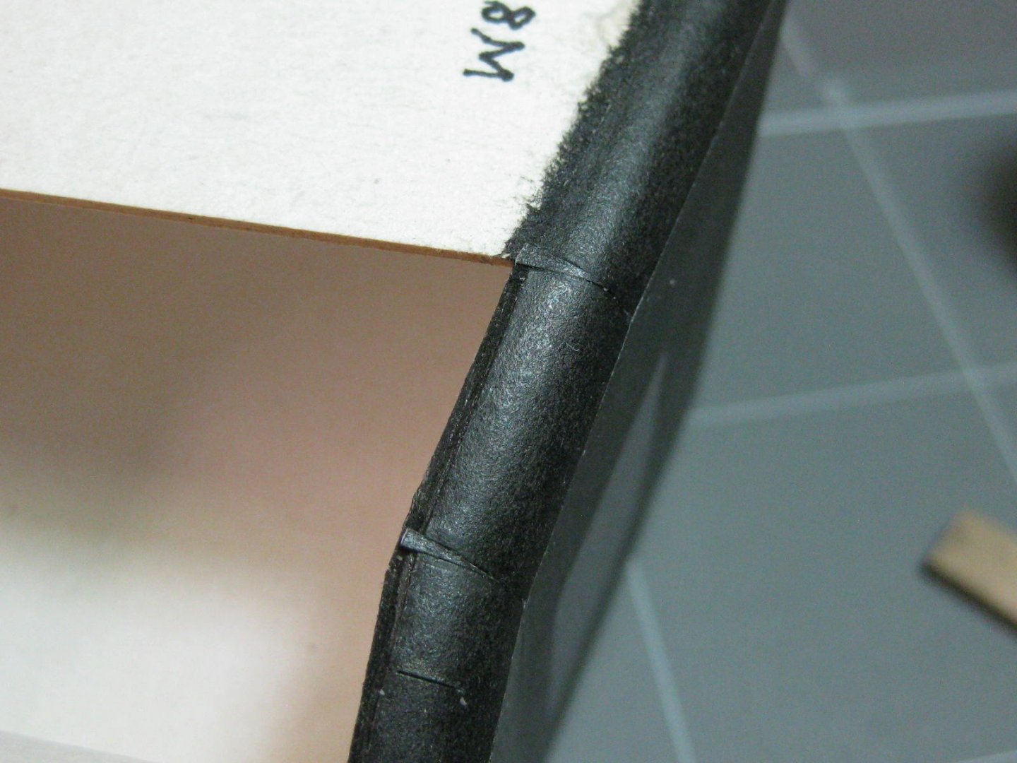
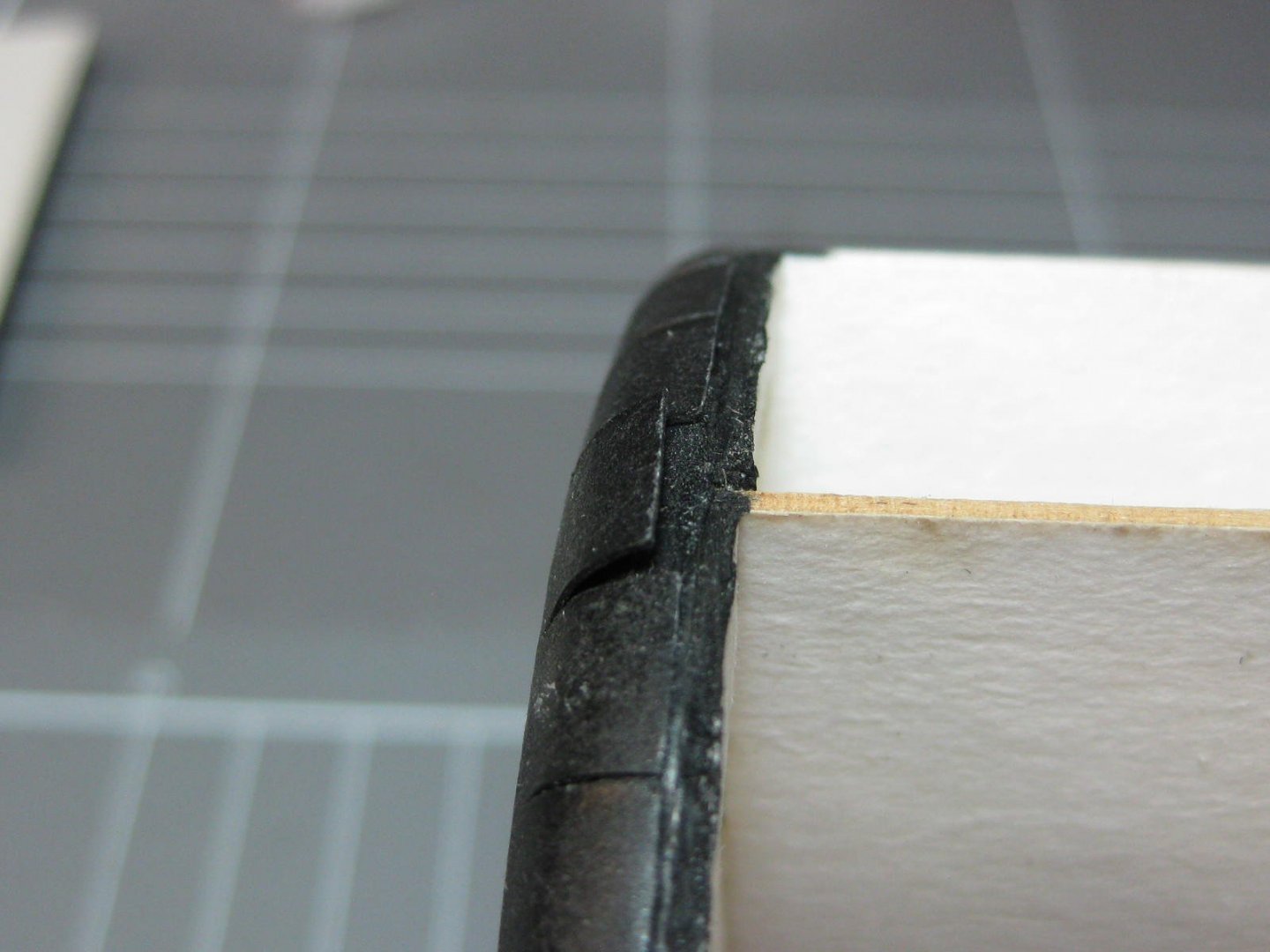
Hi Slog, I've found that when skinning things like the turret sides it's best to glue a piece of scrap behind the join and roll and glue the join together first, then slip the skin over the LC frame rather than gluing the skin to the frame and then finishing off the join. A notch would need to be cut into the top or bottom to clear the joining strip, and dry-fitting is essential of course. A couple of spots of glue is all that's needed to hold the skin to the frame. This stops any starved cow effect, which is usually caused by over-gluing an edge. Check the posts in my Bulgar loco log where I fit the boiler skins to the frames to see what I mean. P.S. I bet that bent ladder ends up getting the better of you and will get replaced . Cheers, Danny
- 244 replies
-
- 4
-
-
- borodino
- dom bumagi
- (and 1 more)
-
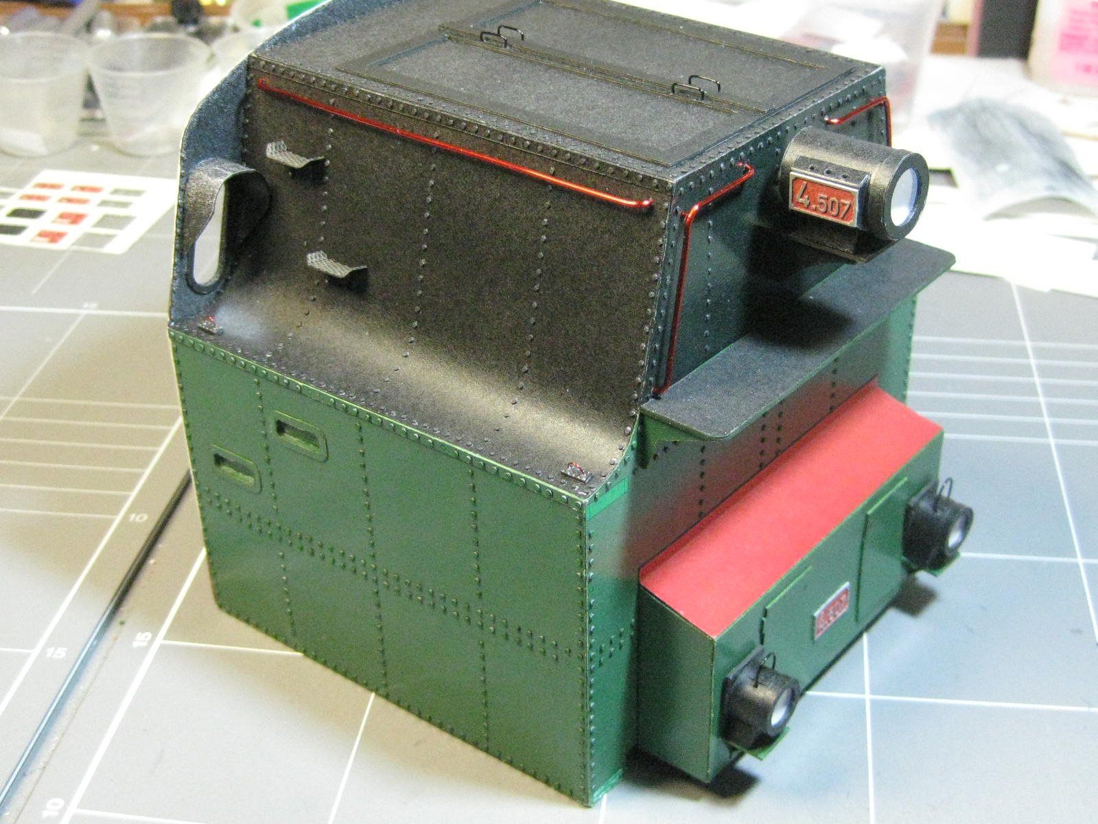
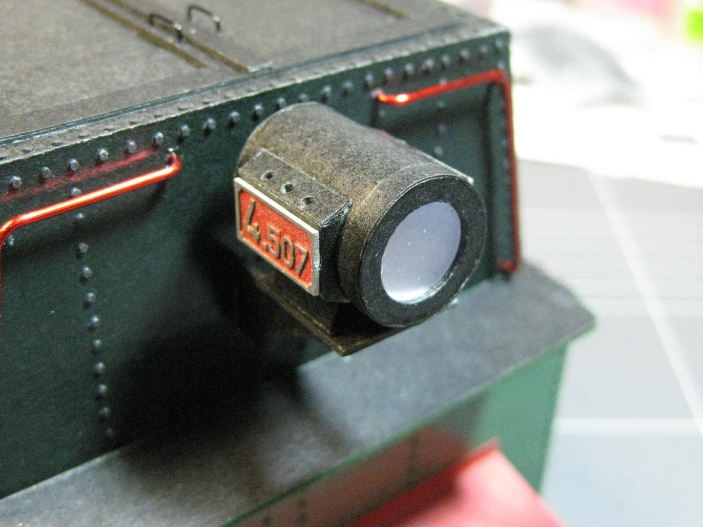
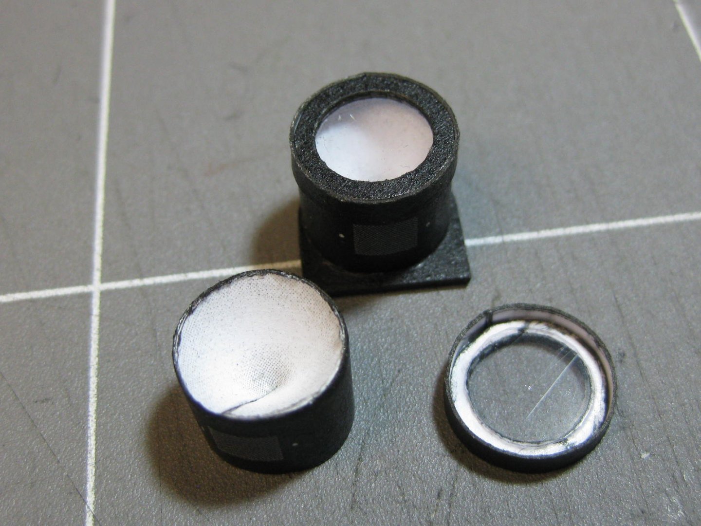
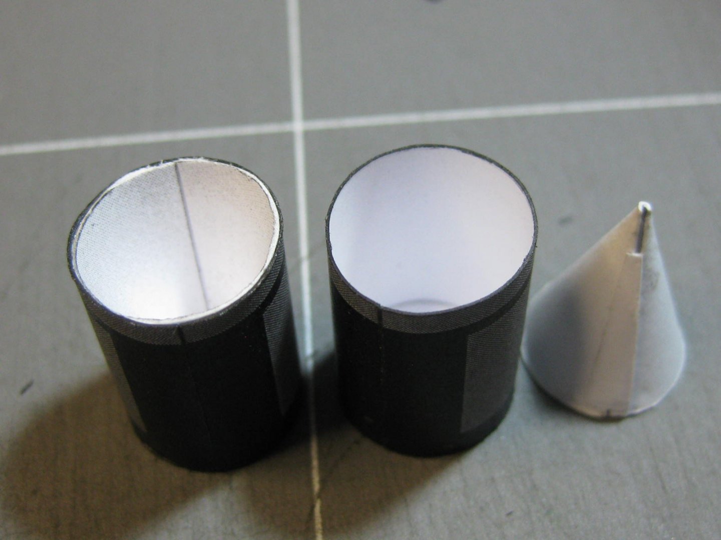
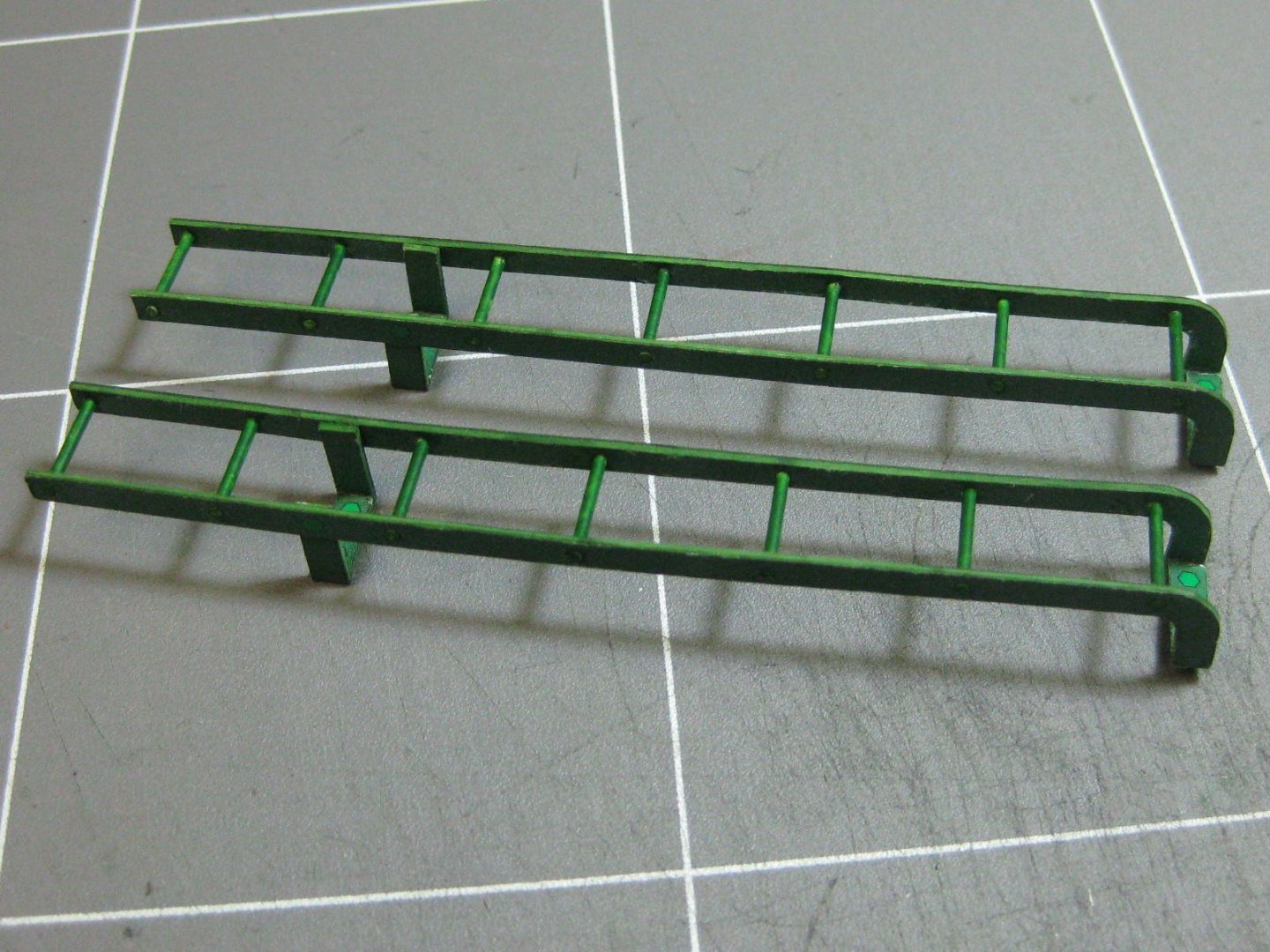
The coal bunker has also been made. I'll fit this to the cab after I've done a bit more detailing to the controls : The ladders and lights : The completed coal bunker : Danny


- 150 replies
-
- 21
-
-
More plumbing fitted : I've also fitted the cab to the boilers and added a temporary support under the front of the boiler while work continues : Danny


- 150 replies
-
- 14
-
-
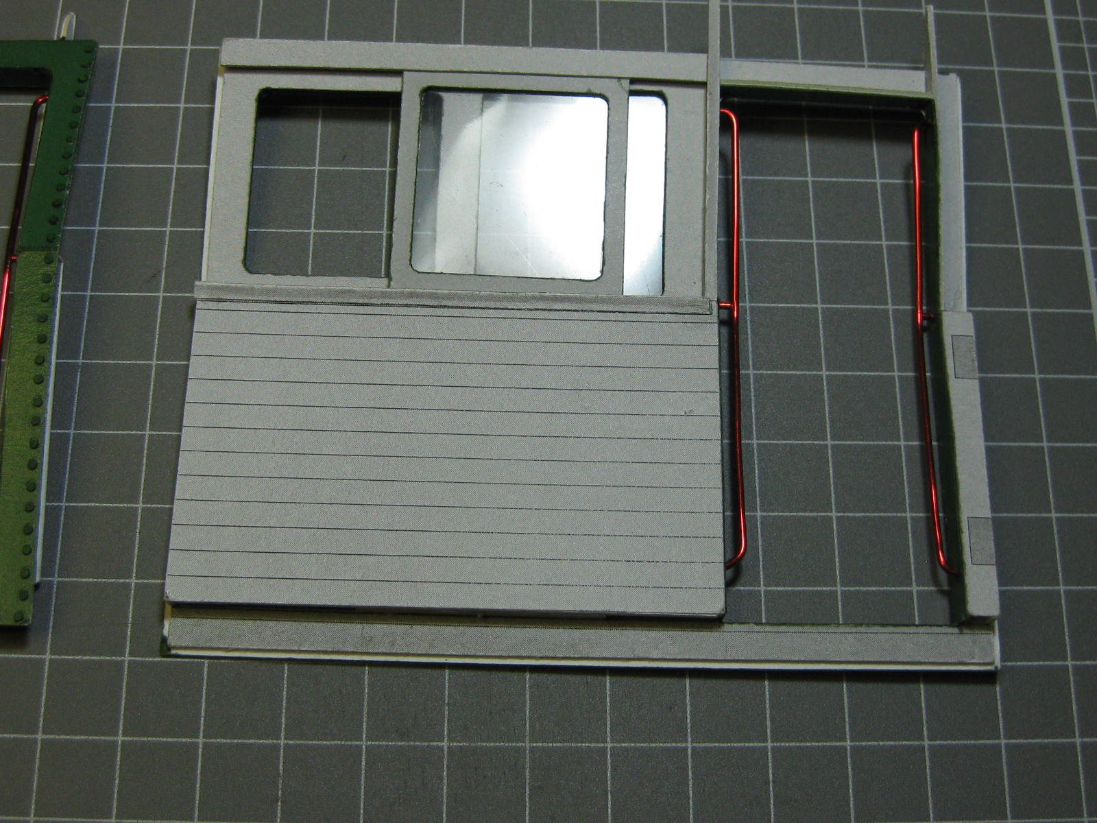
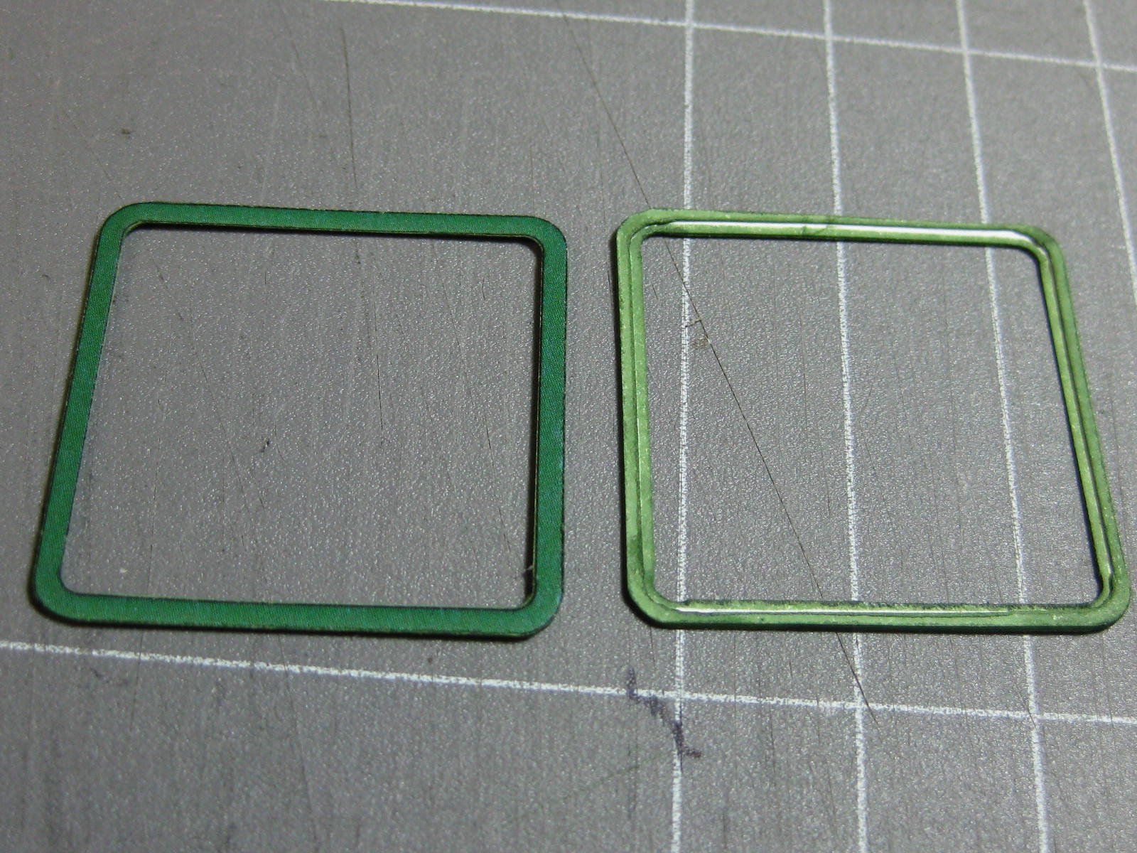
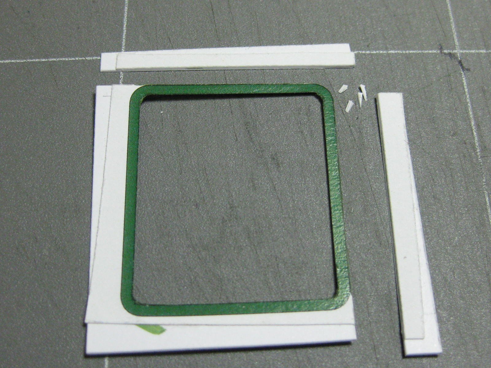
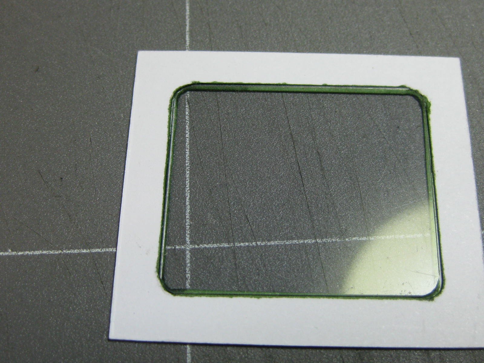
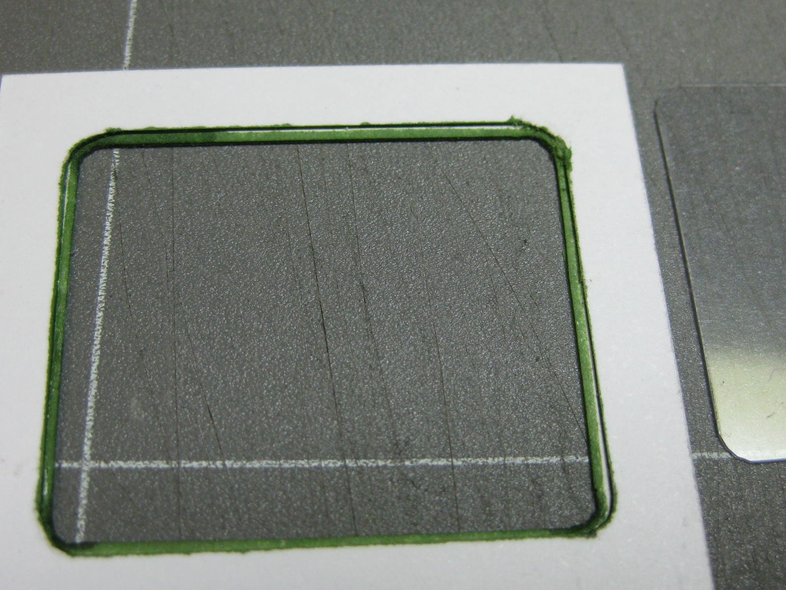
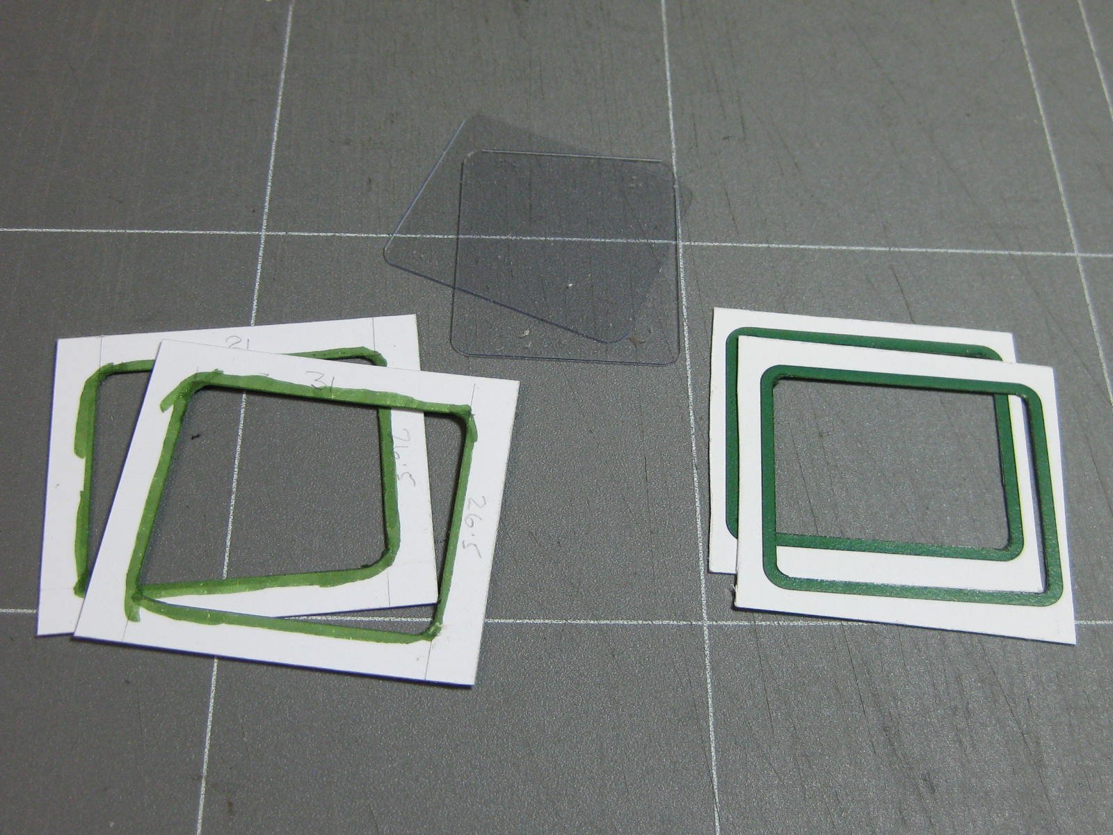
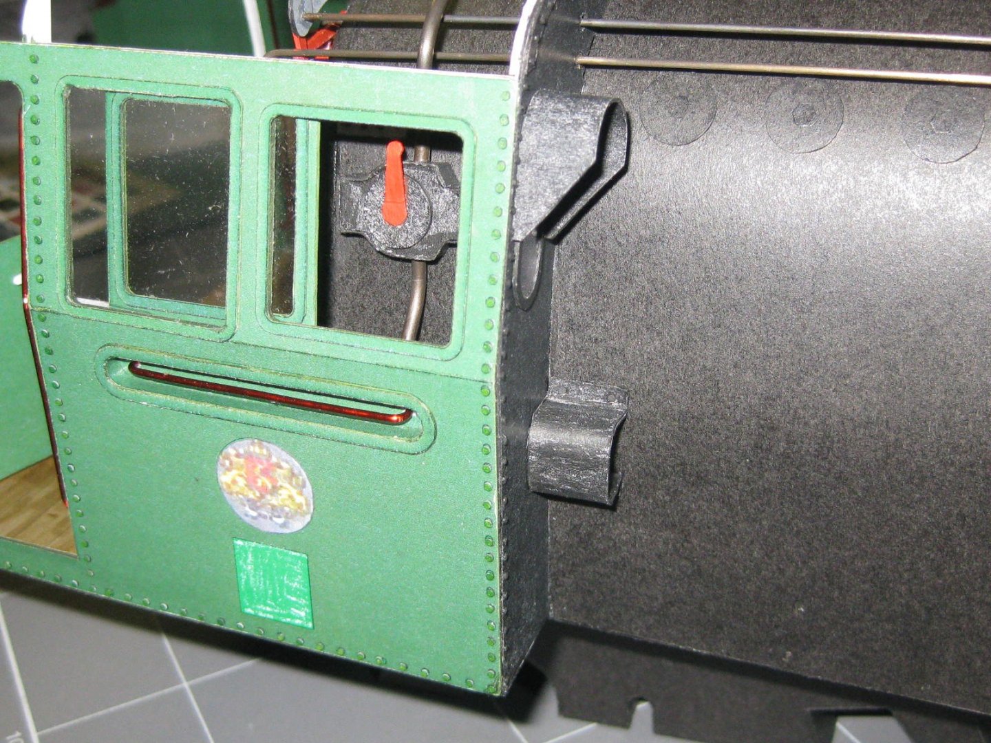
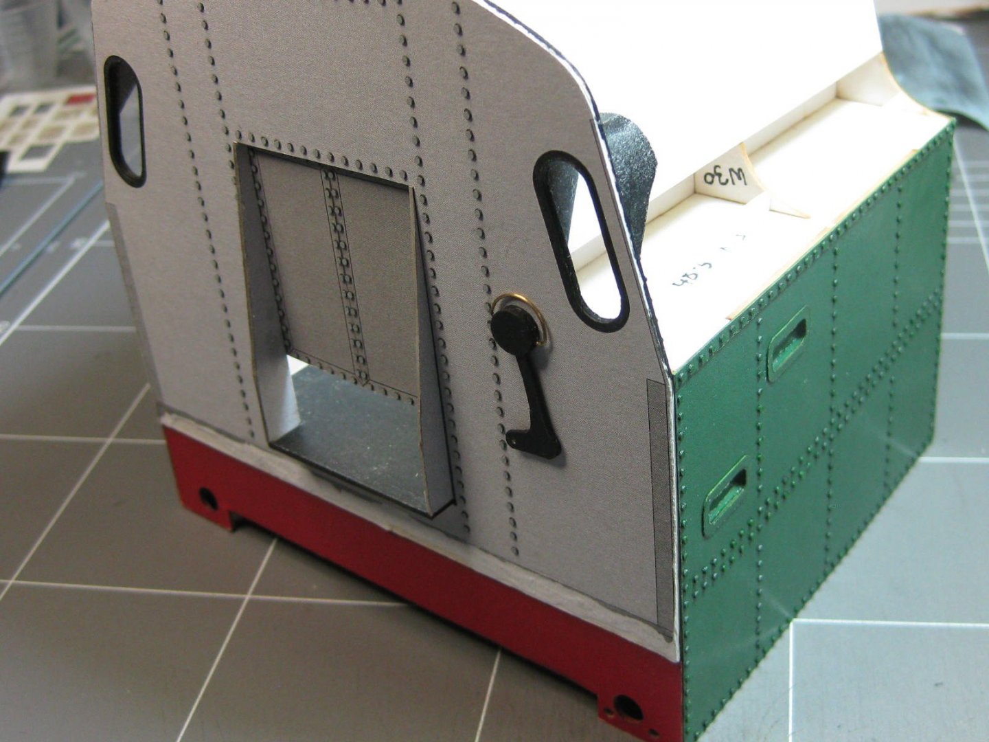
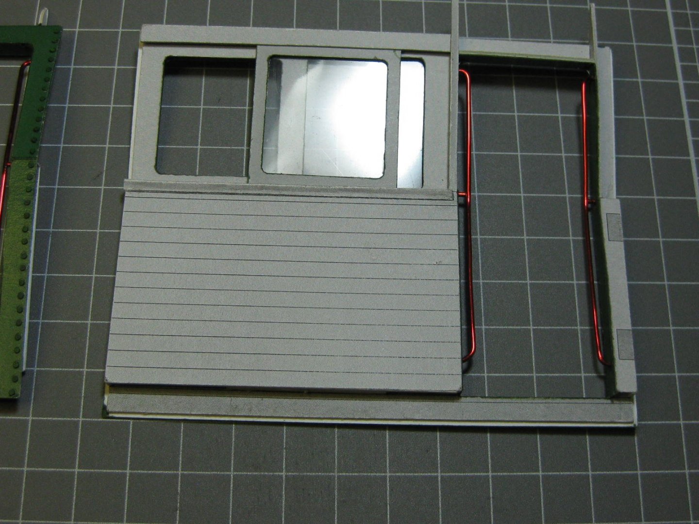
No, I won't be ripping anything out . I have used those pics and the website they came from to enhance my model a bit, so thanks for posting them . I'm leaving the lubrication pipes where they are as they don't interfere with anything else. I won't be going to the extent that the other guy did - he's used some 3D printed fittings which I can't get for a few weeks (but I ordered some). Most of the difference with our models is that he's painted his, which I won't be doing. I've made the two sides of the cab. Here's my procedure for glazing the windows : And the completed sides : Danny


- 150 replies
-
- 14
-
-
QUICK-FIND INDEXES to BUILD LOGS FOR KITS
Dan Vadas replied to Dan Vadas's topic in - Index of all kits by brand and subject
Sorry Bruce, NO to both questions. Scratchbuilts are nearly all one-offs so an Index would be fairly useless. Use the Search function in the Scratchbuild forum to find any specific ship you may be looking for. You may be able to find P.O.F. builds the same way if the builder has identified their model as such in the title. Danny -
Oh ........ dear . Now THAT is nice - way beyond my pay grade . The thing is I'm building in paper because I don't want to paint, or as little as possible anyway . Thanks Pav. Danny
-
Swann-Morton Scapel
Dan Vadas replied to Landlocked123's topic in Modeling tools and Workshop Equipment
By now I've probably changed about 400 of these blades. I simply slip the blade on like Shipman does using just my fingers, but I use a needle-nose pliers to pull it back off after cutting myself ONCE using just my fingers (once bitten, twice shy ). I didn't bother getting one, but I believe Swann-Morton make a special tool for replacing blades. A waste of money IMHO. Danny -
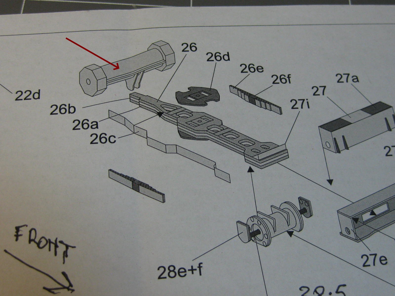
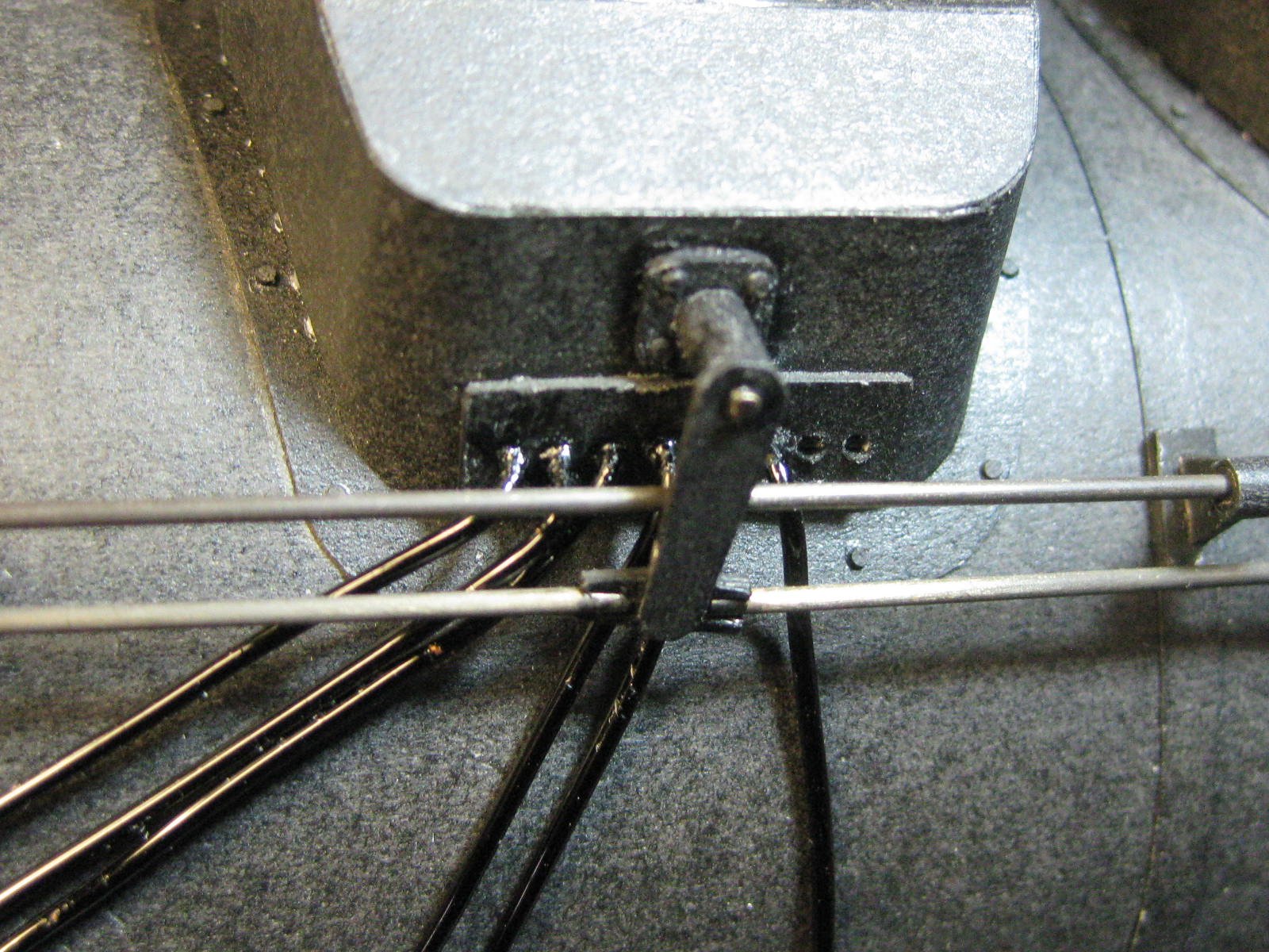
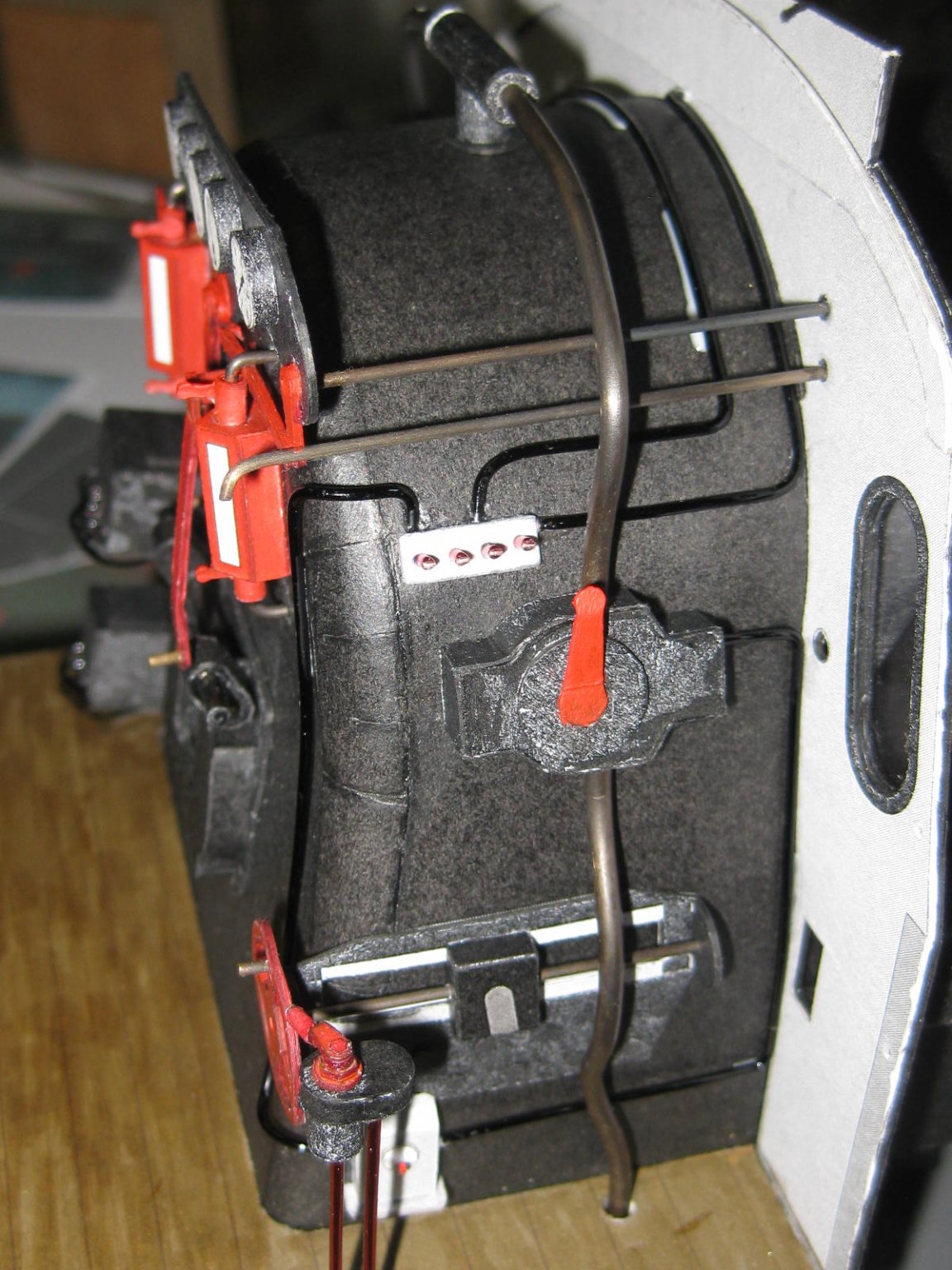
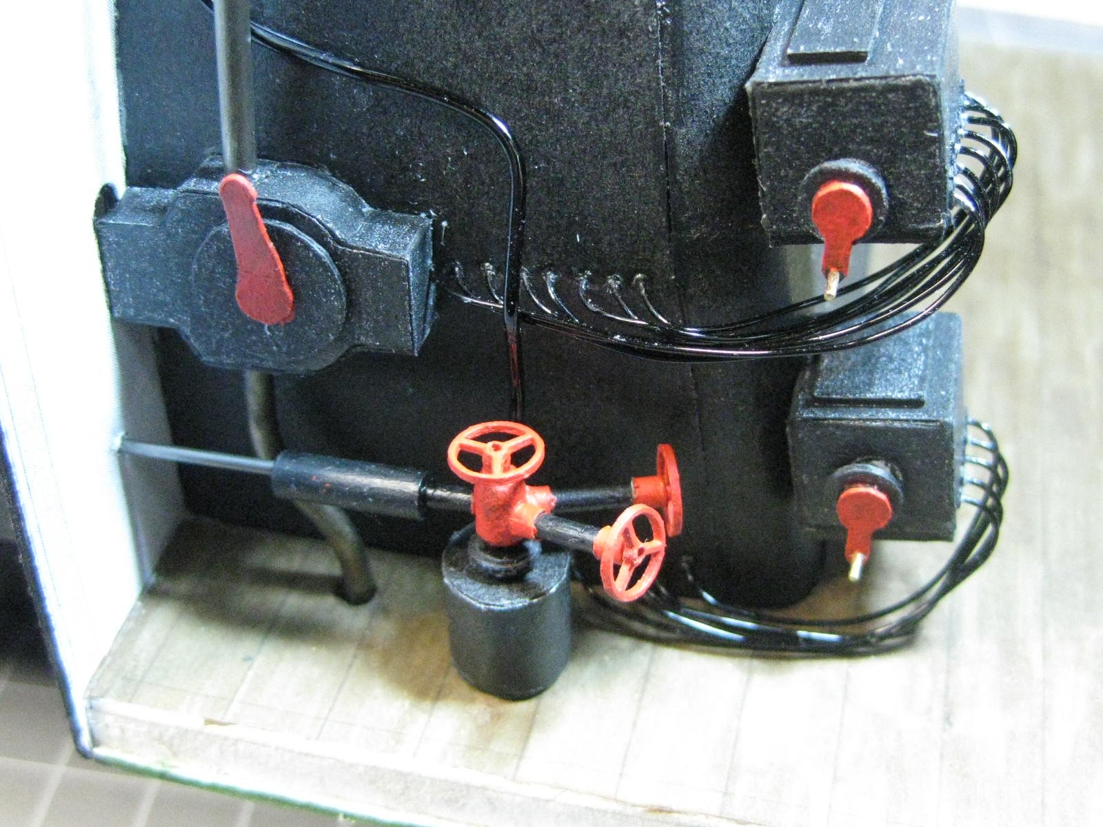
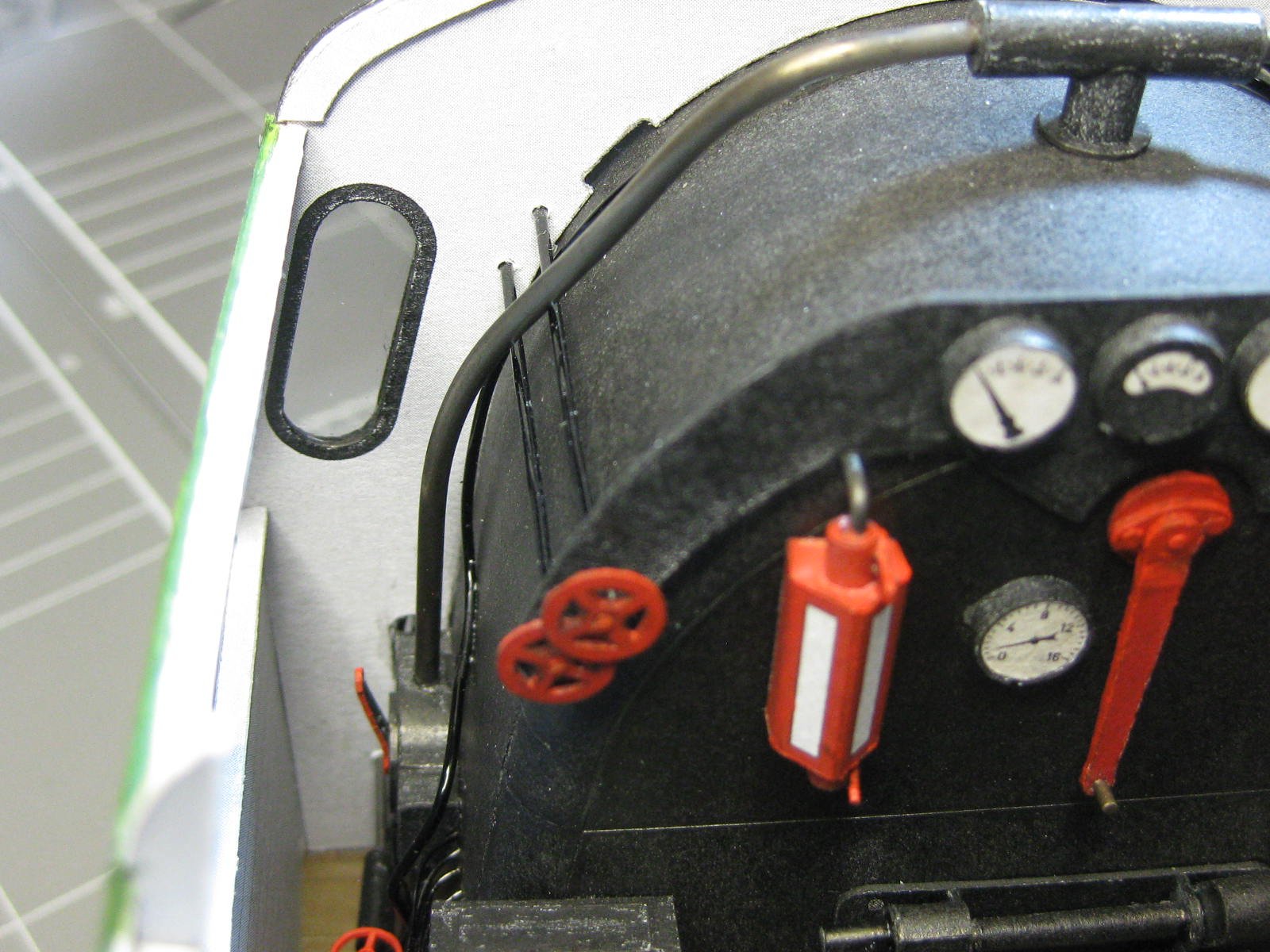
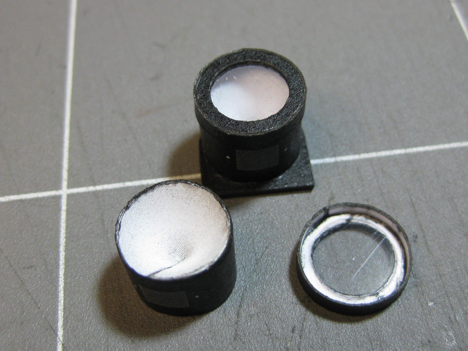
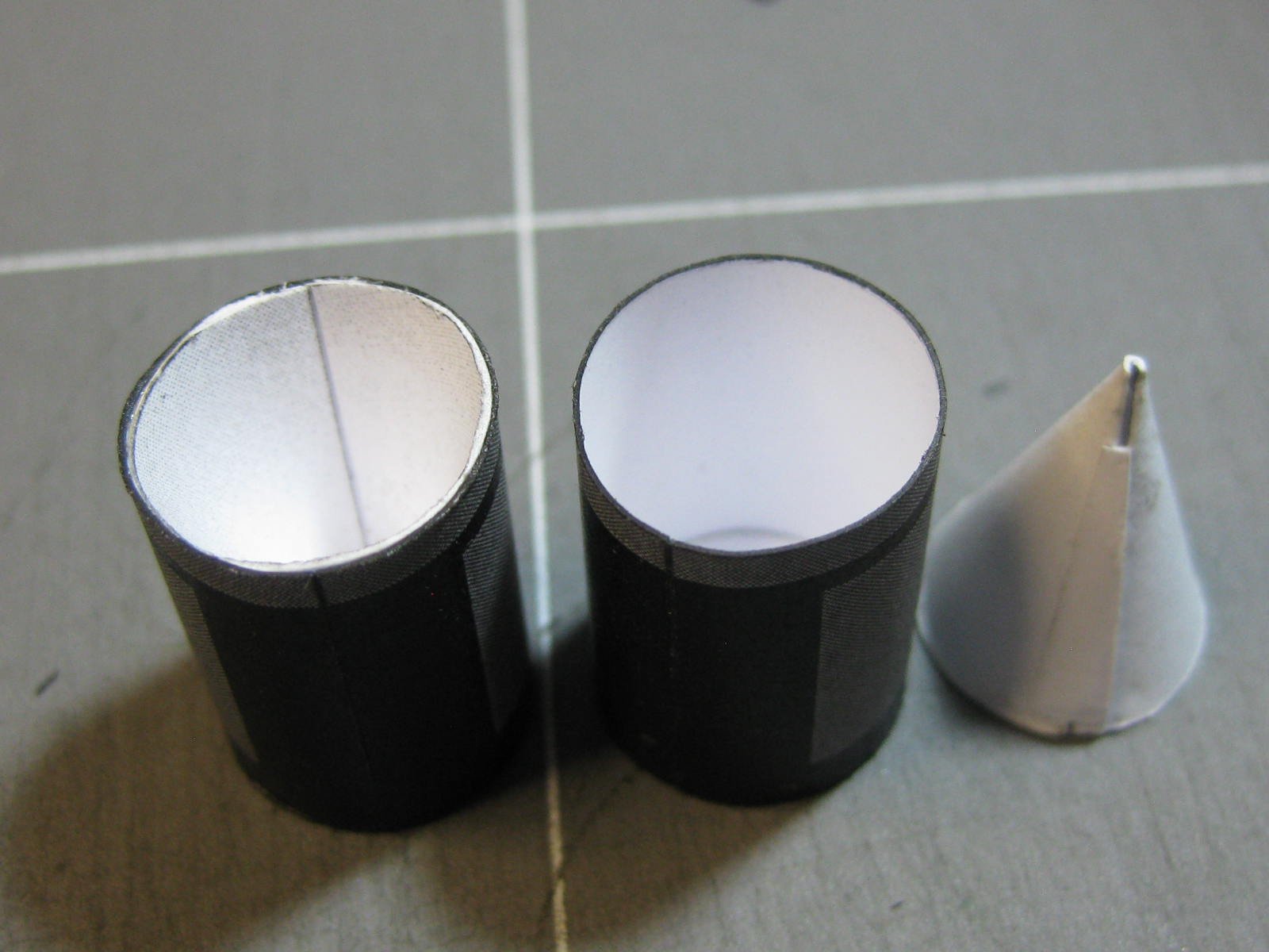
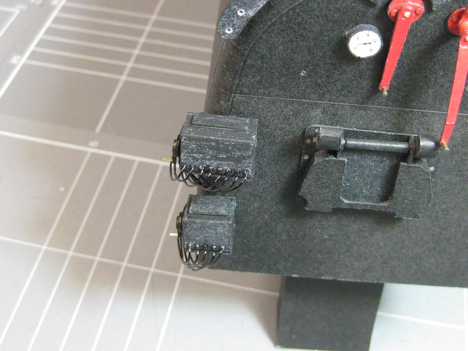
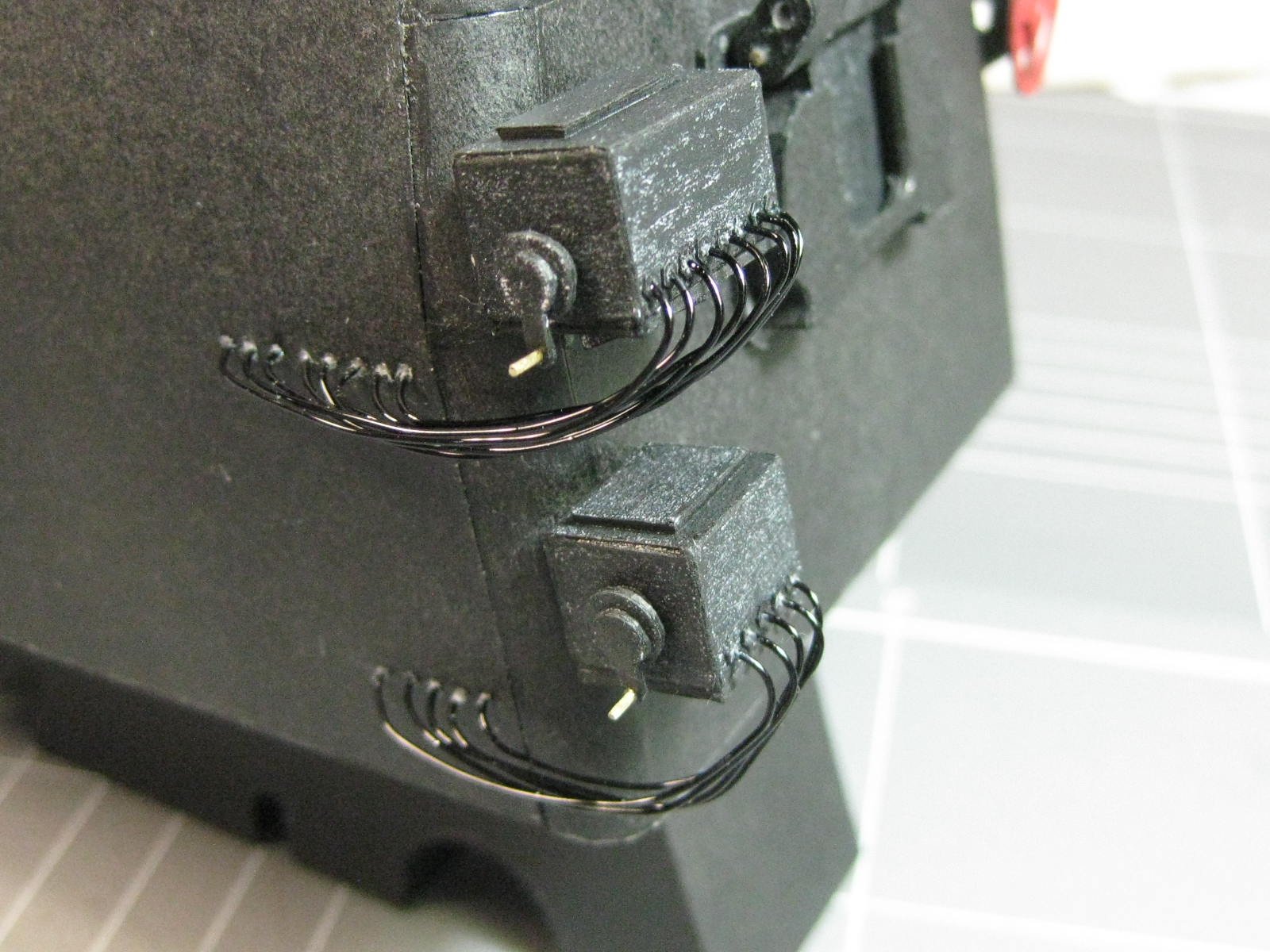
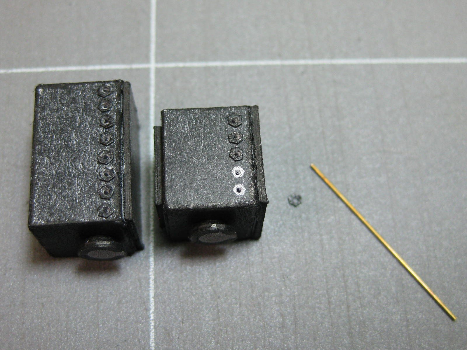
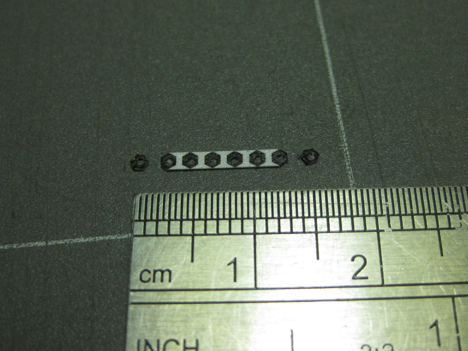
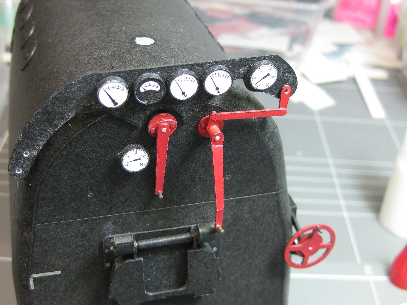
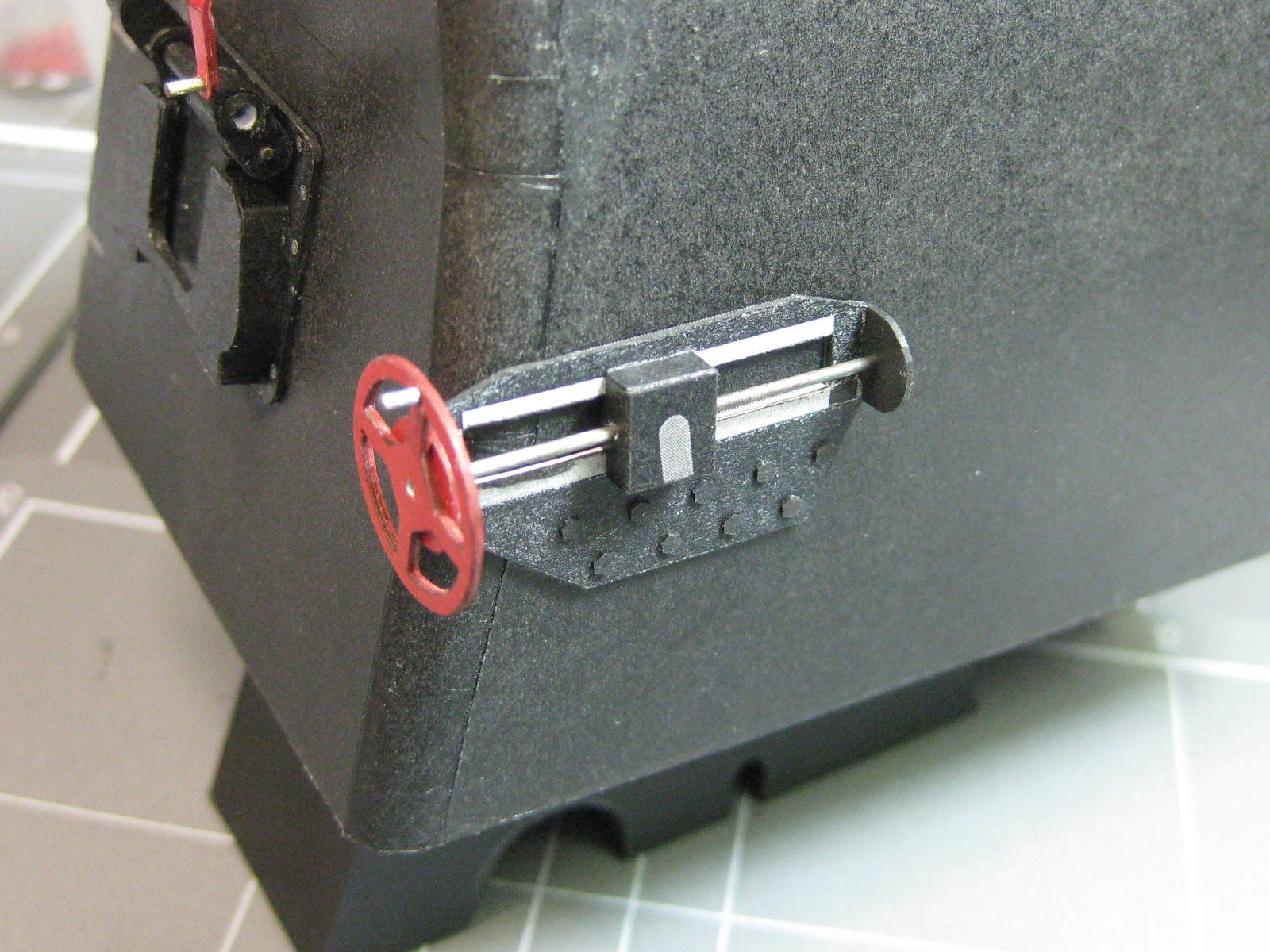
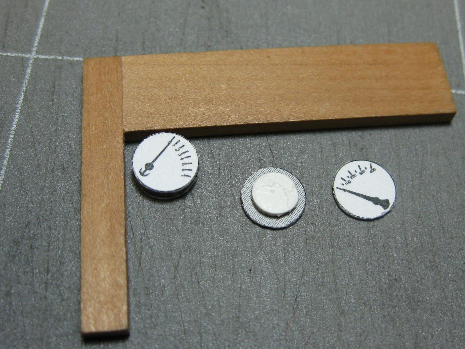
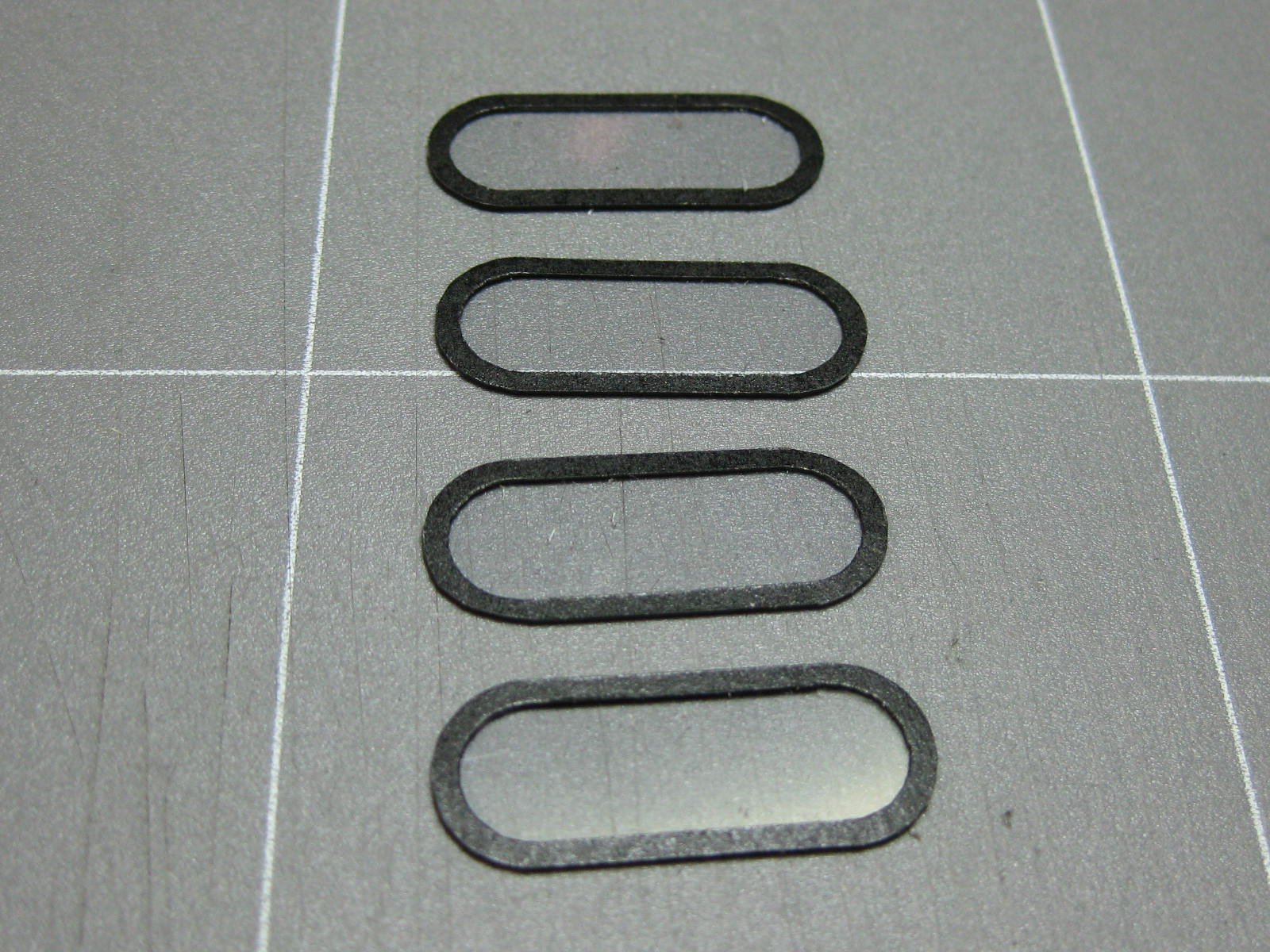
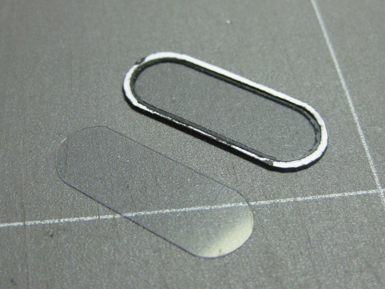
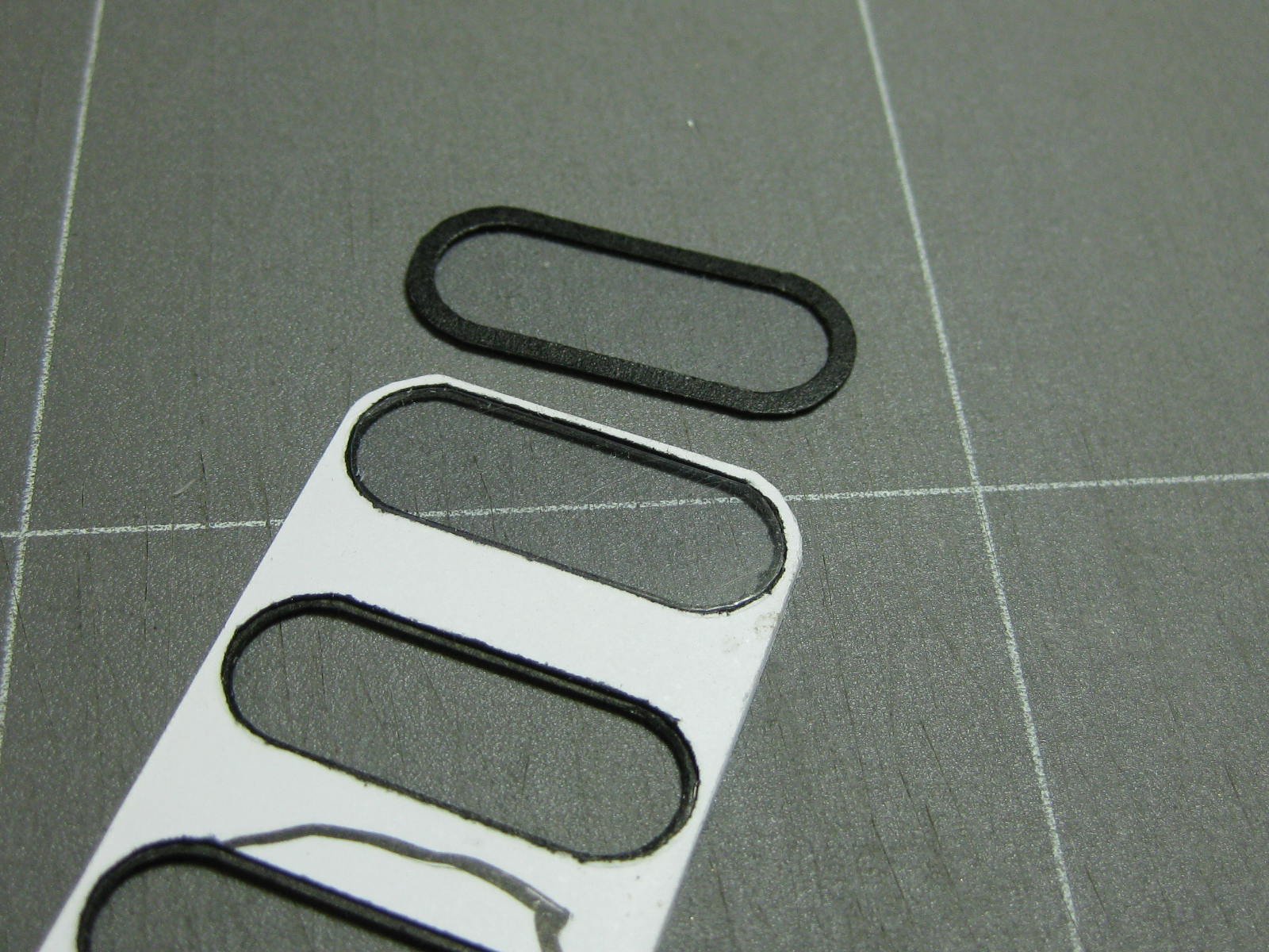
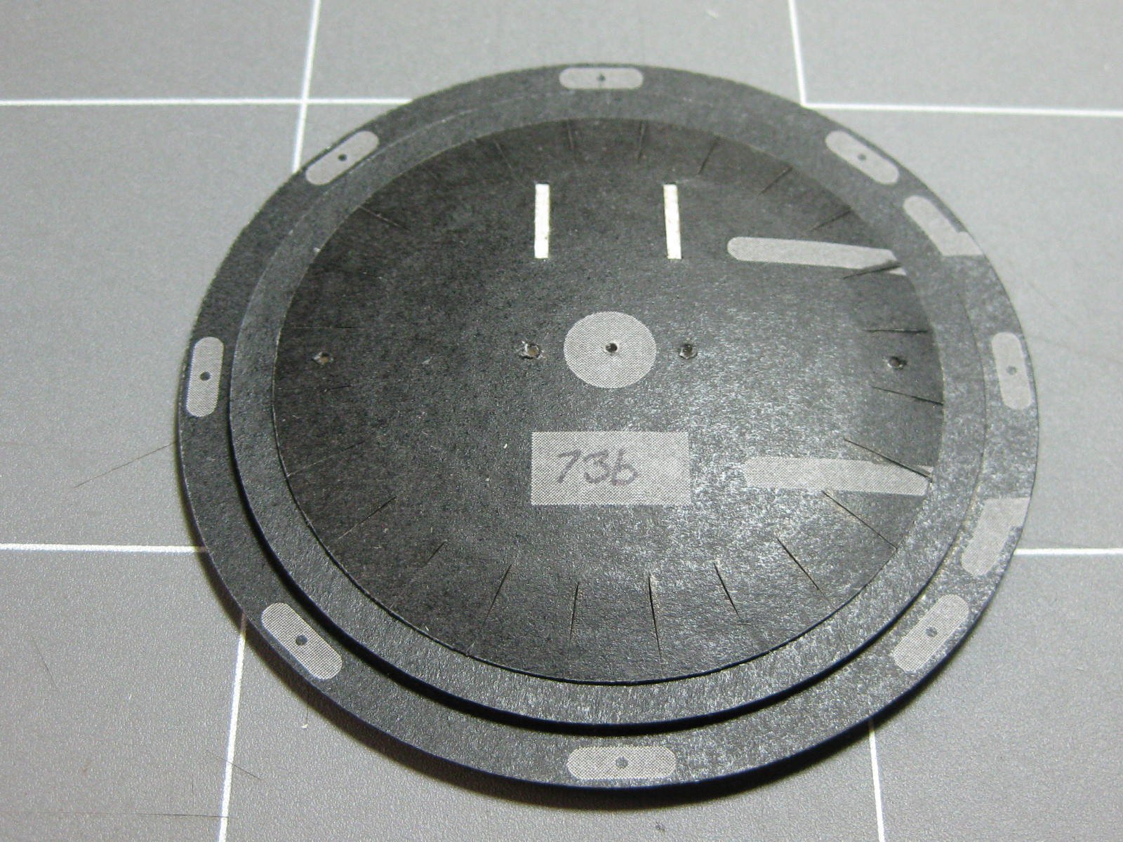
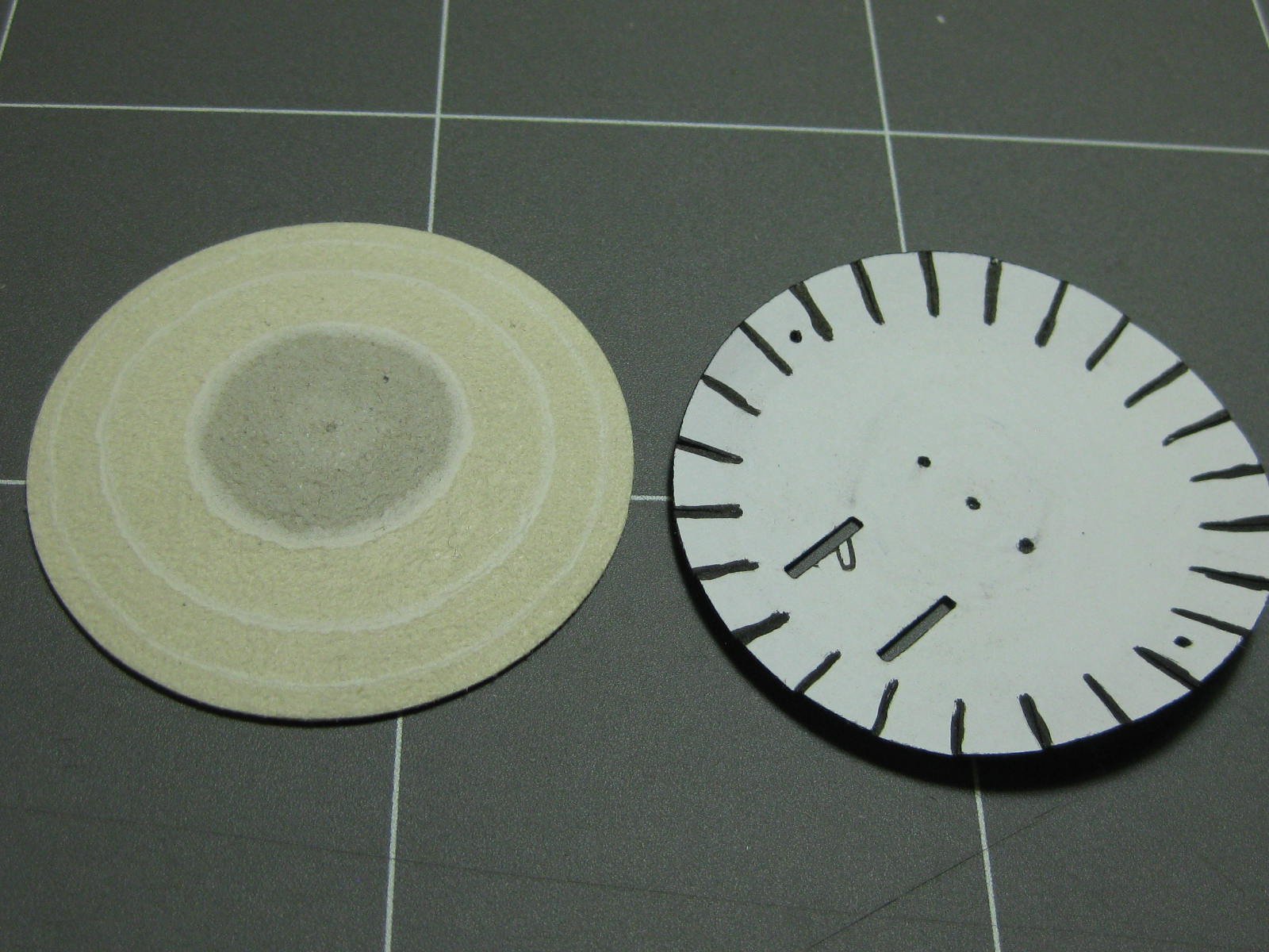
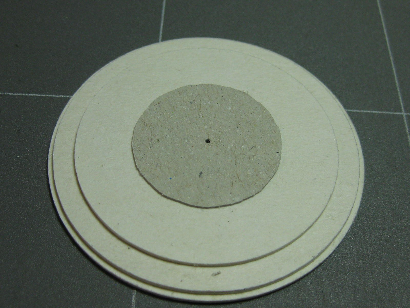
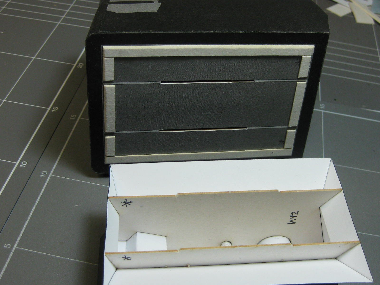
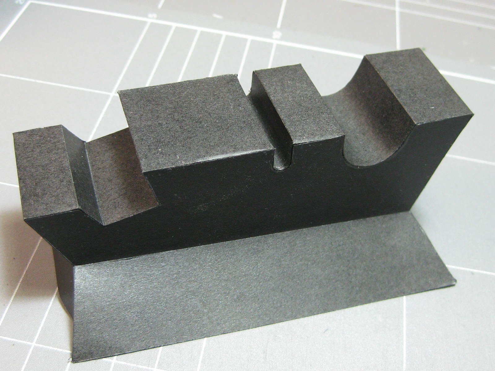
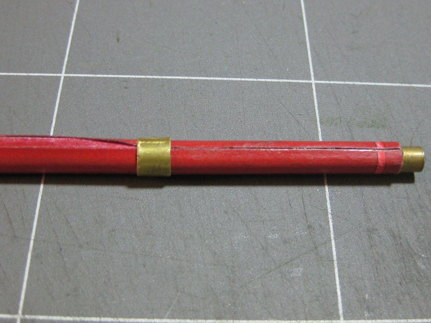
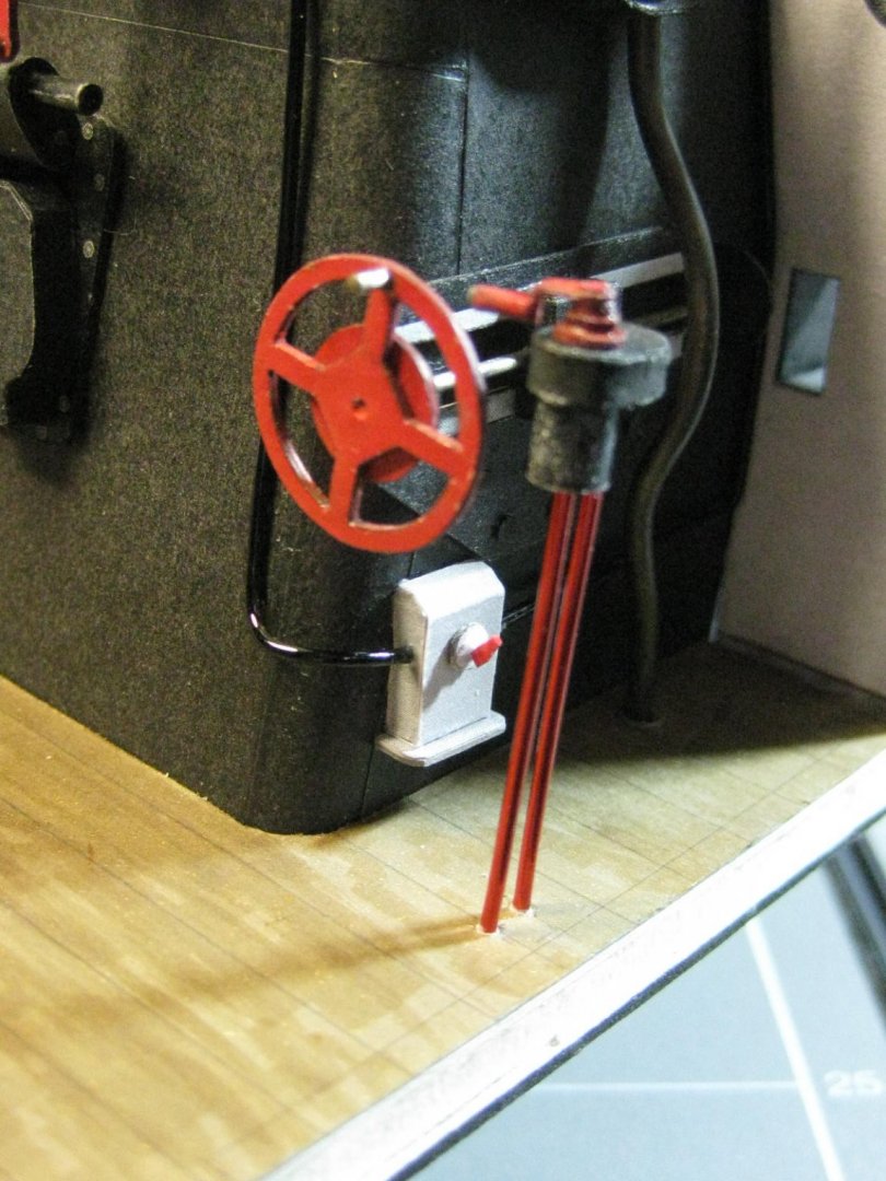
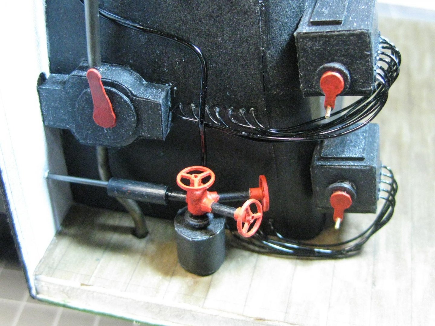
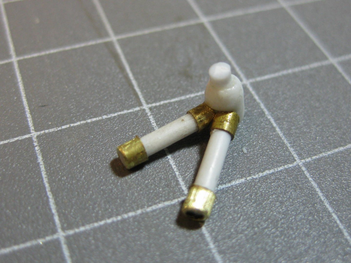
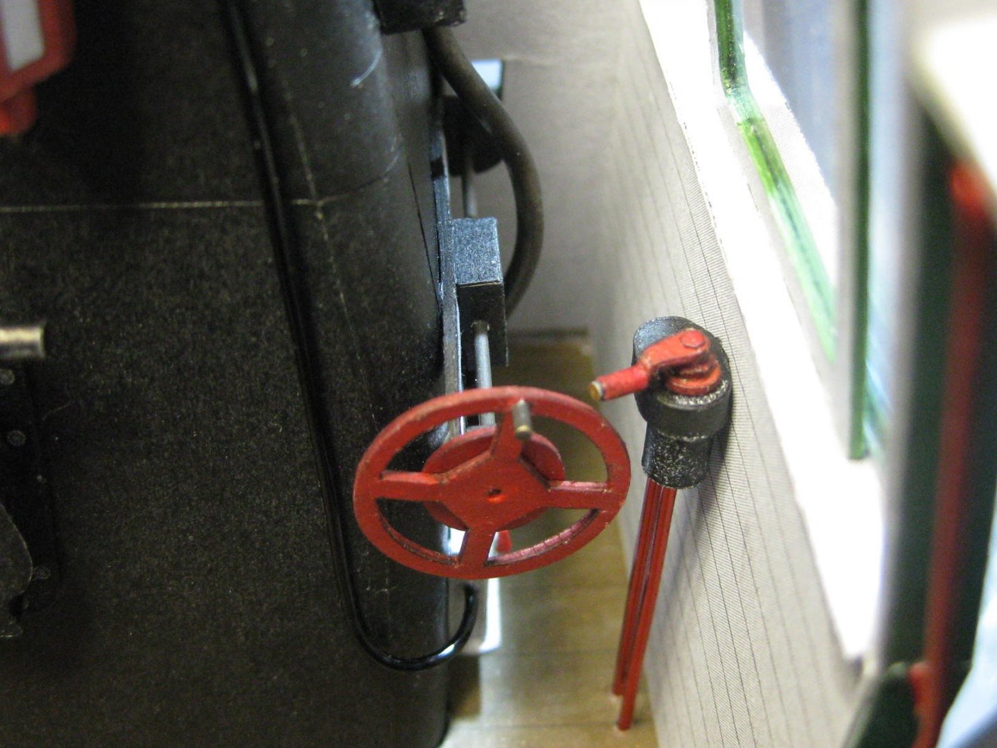
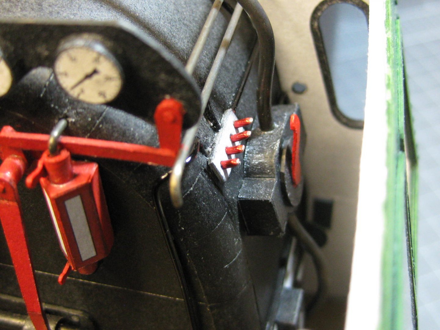
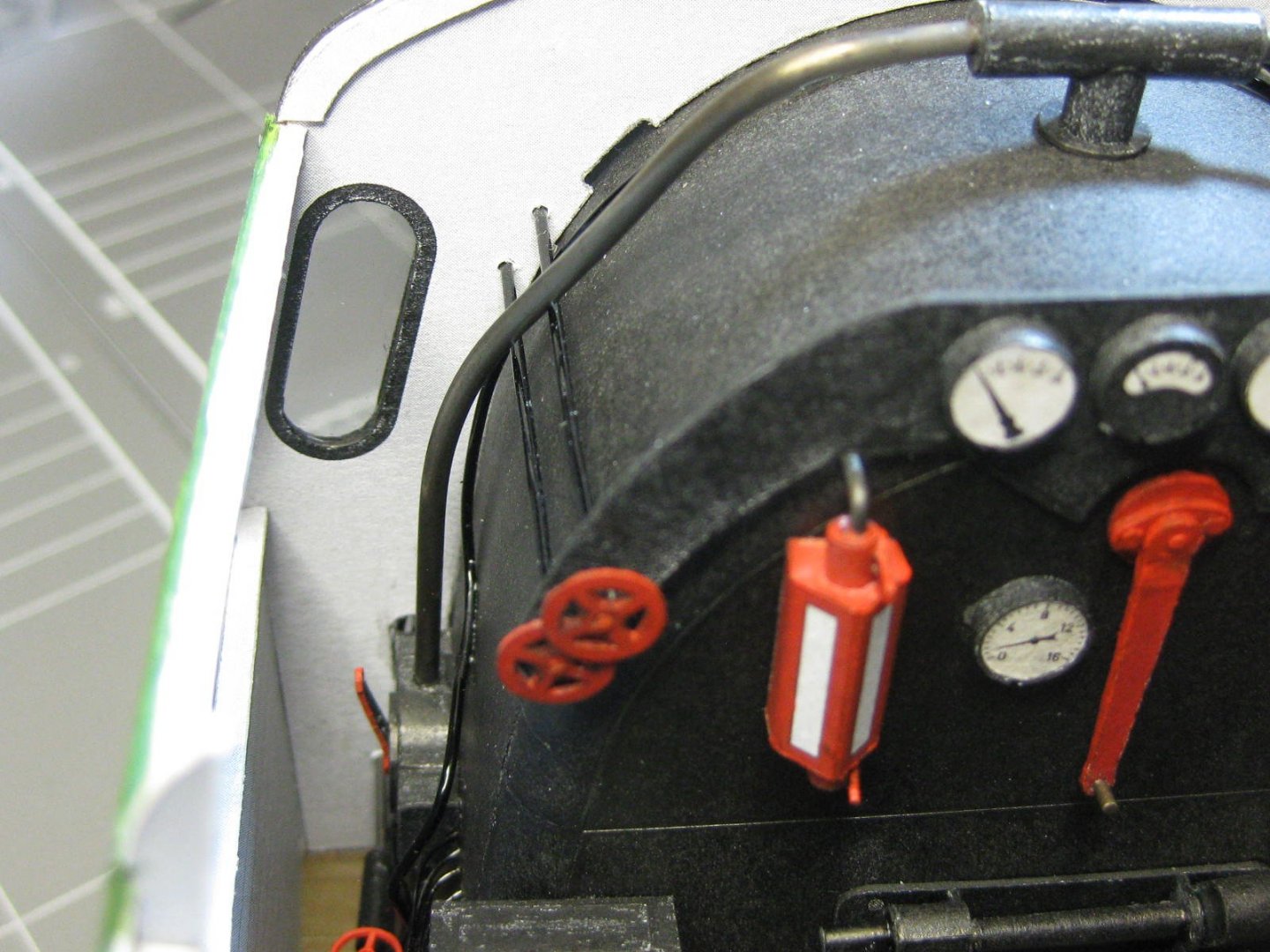
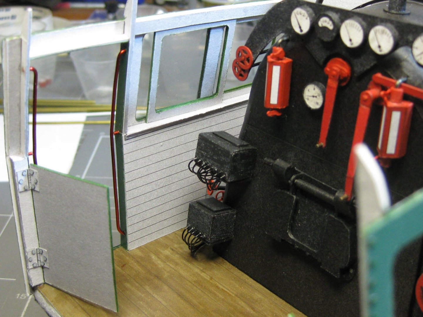
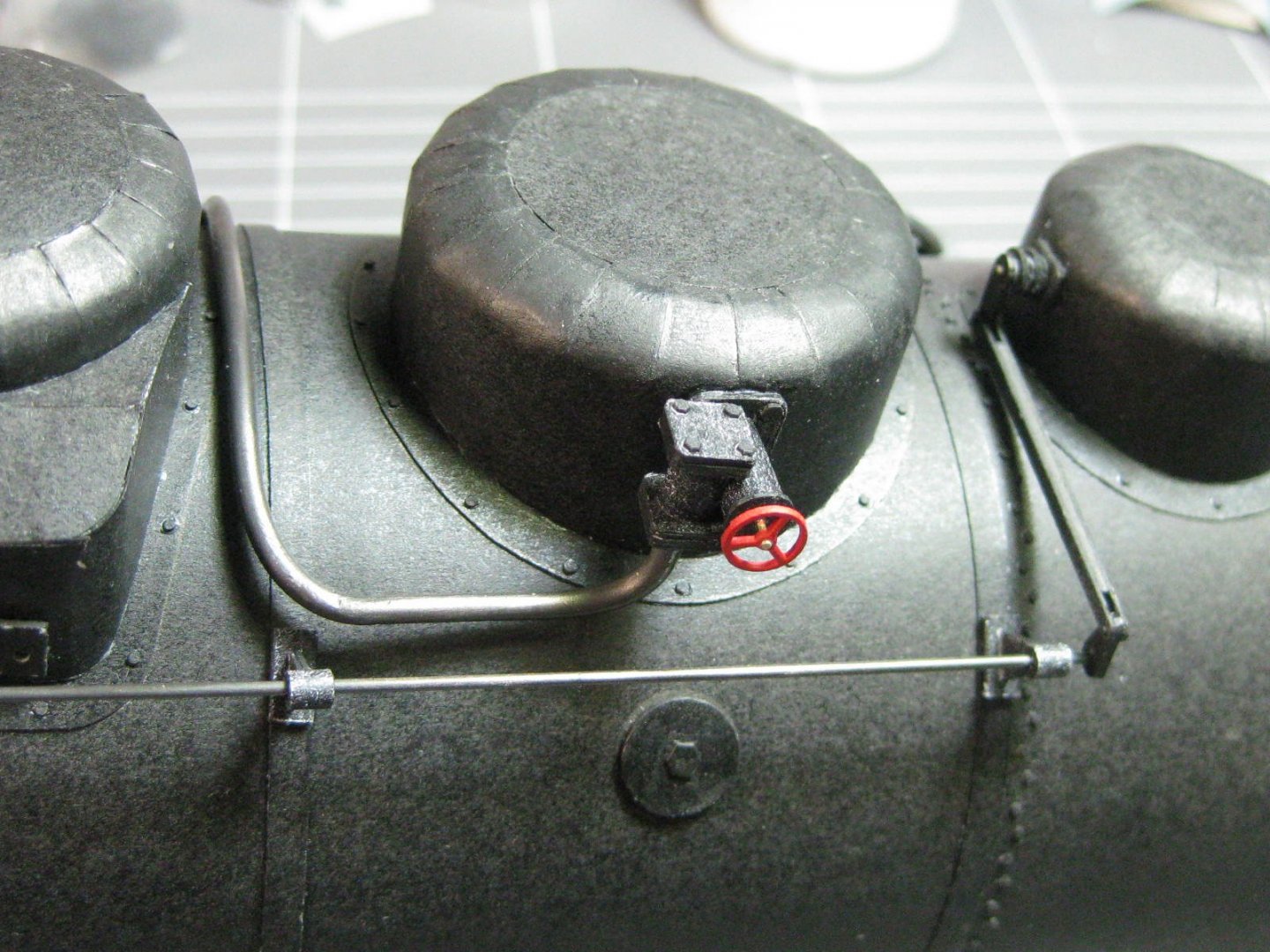
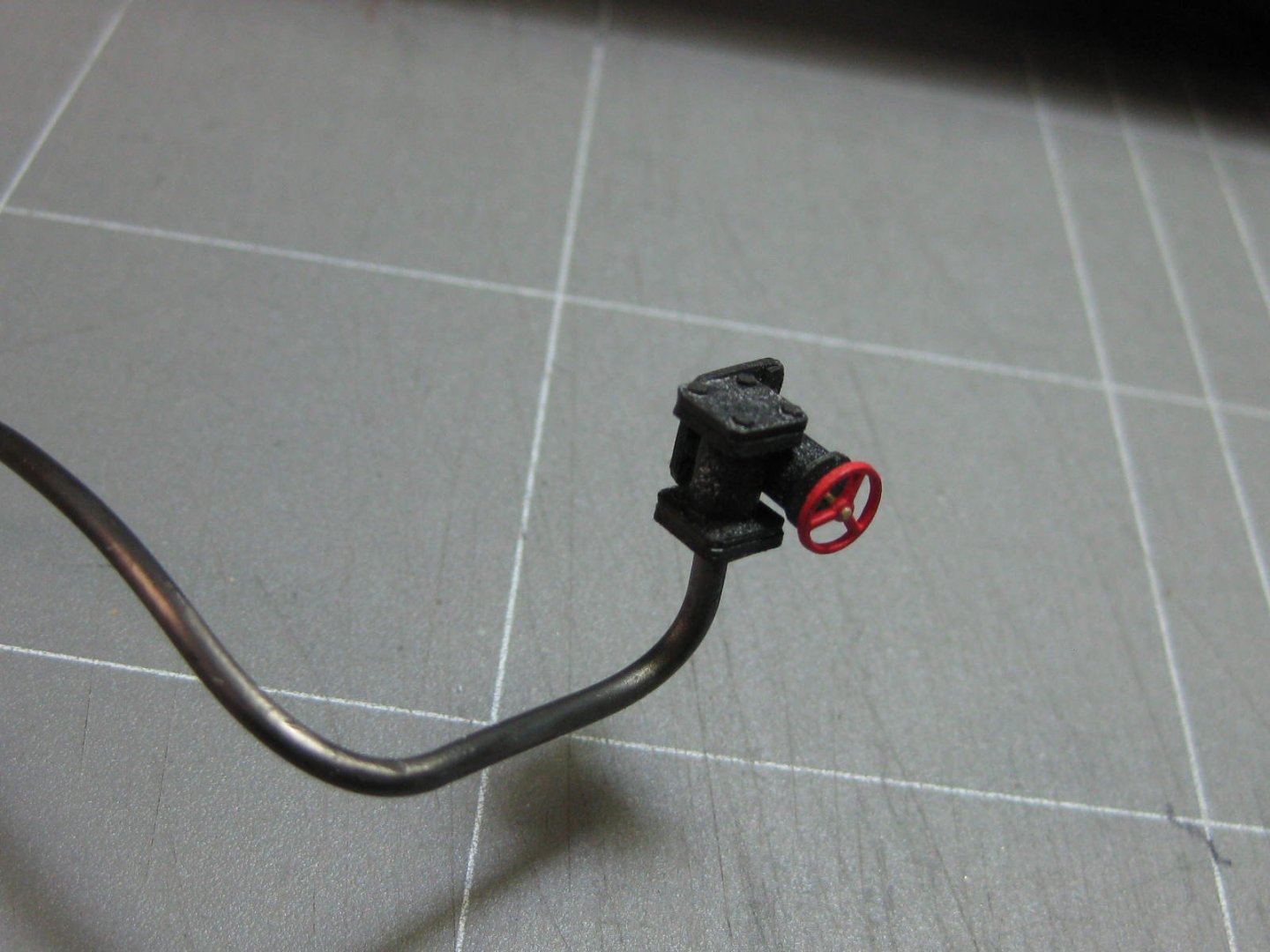
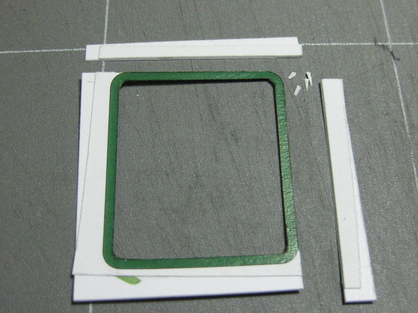
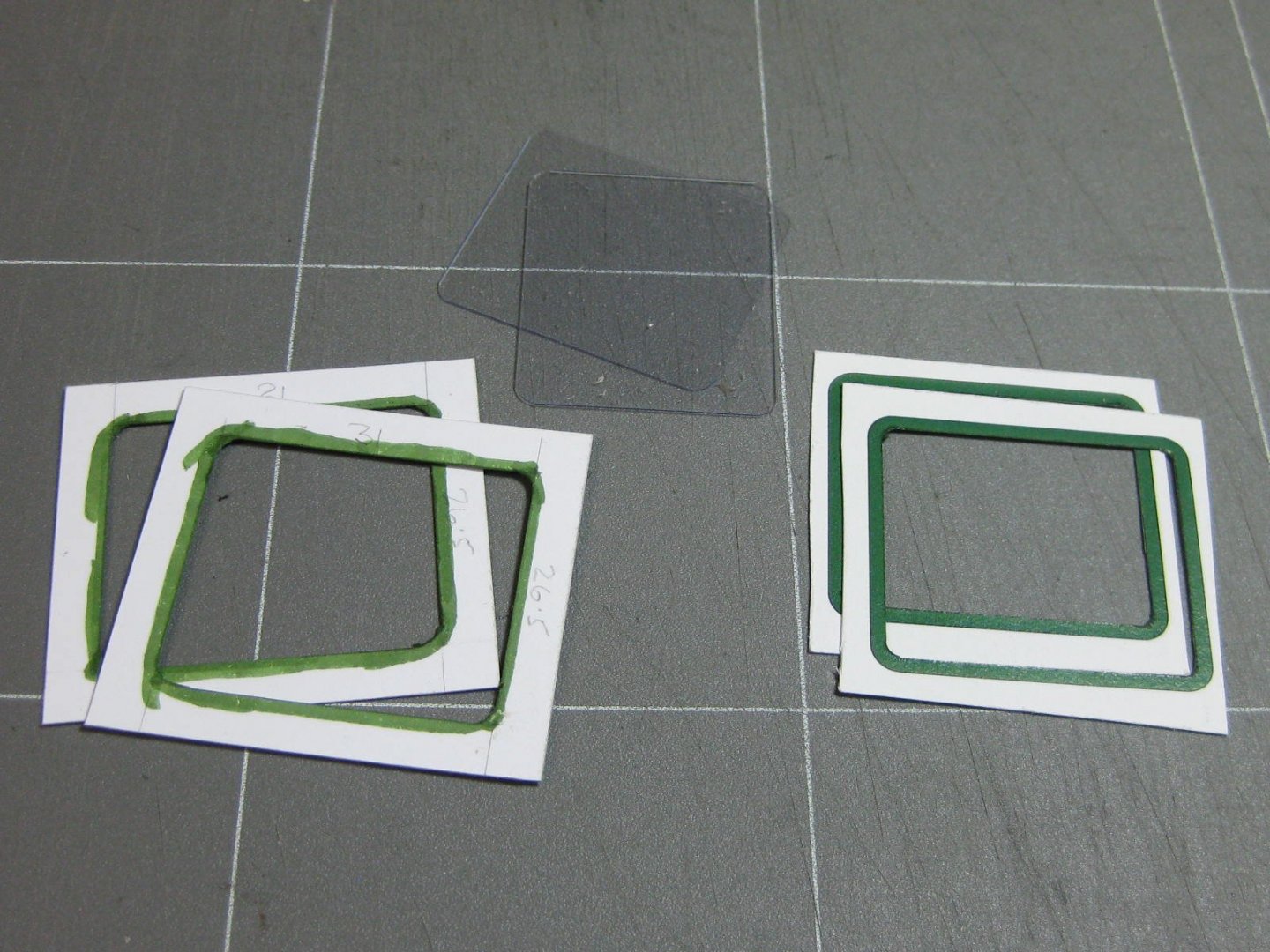
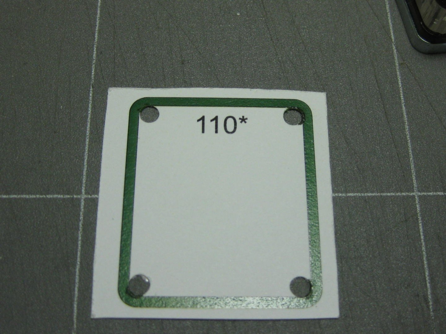
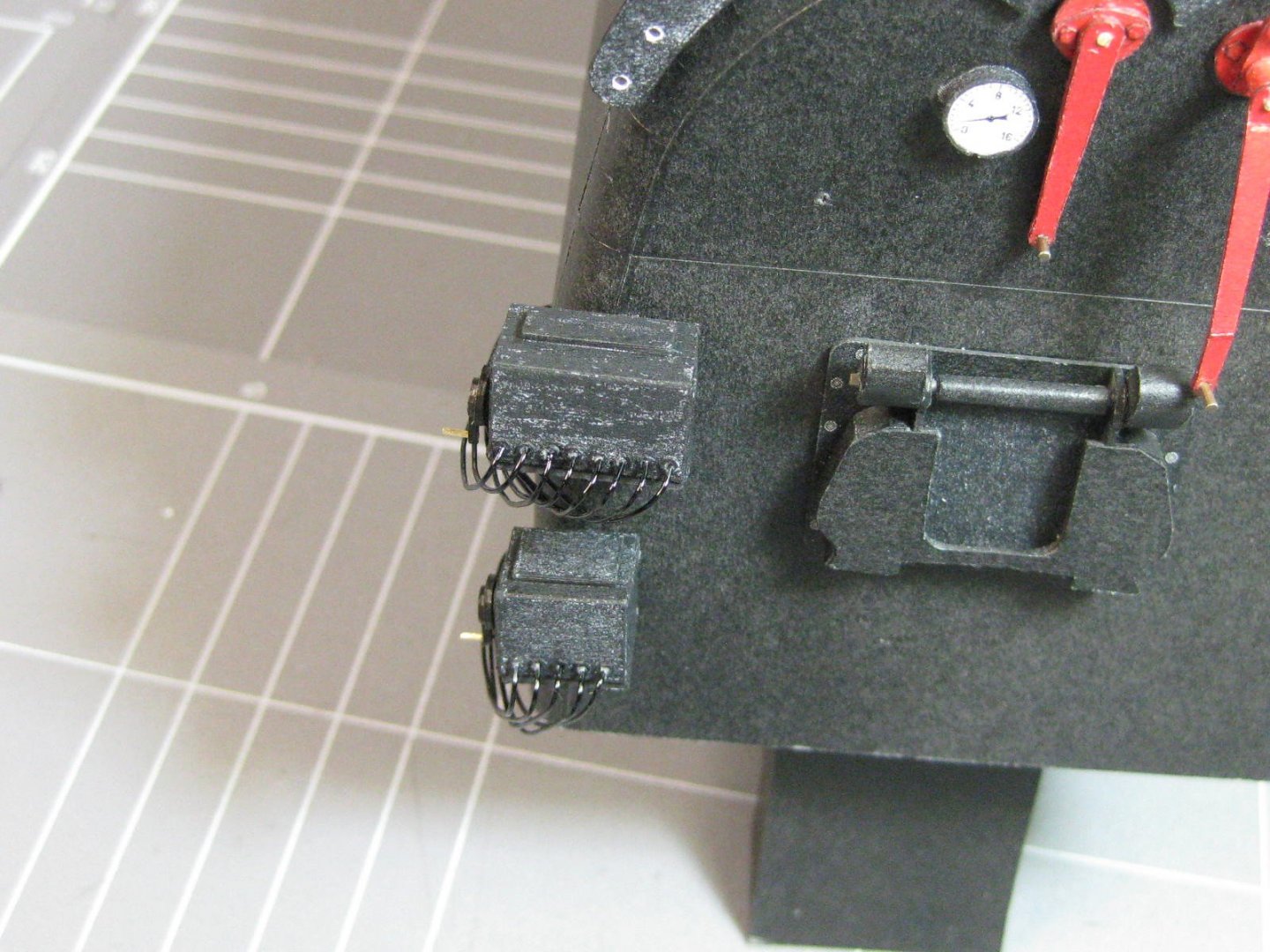
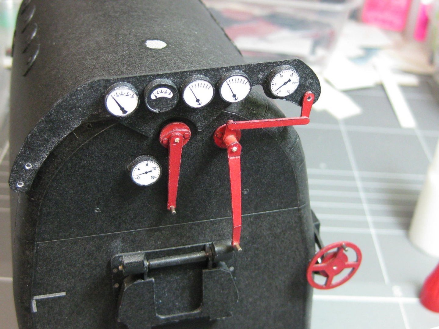
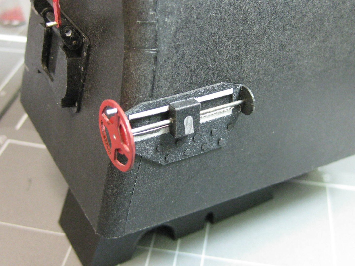
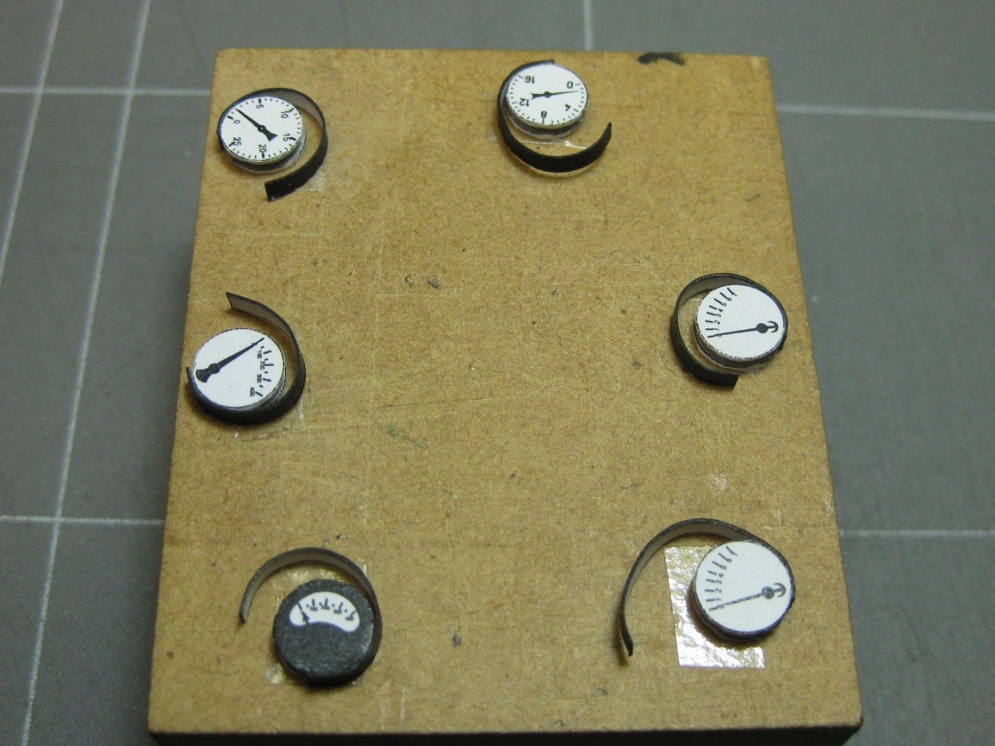
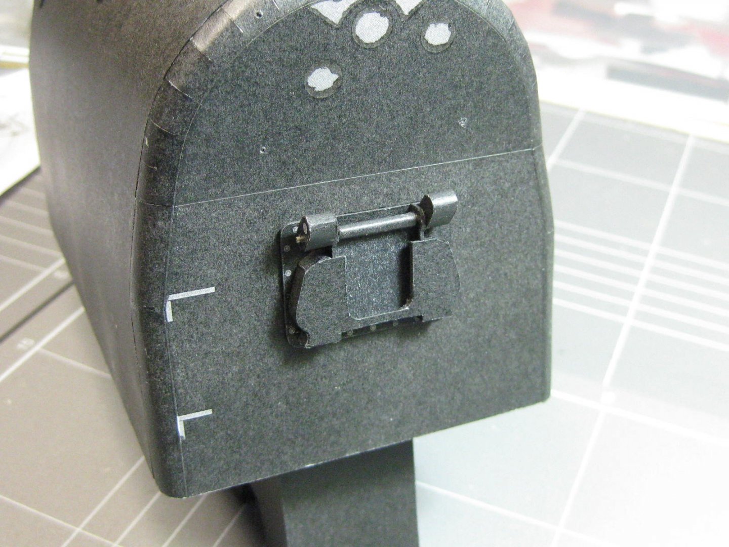
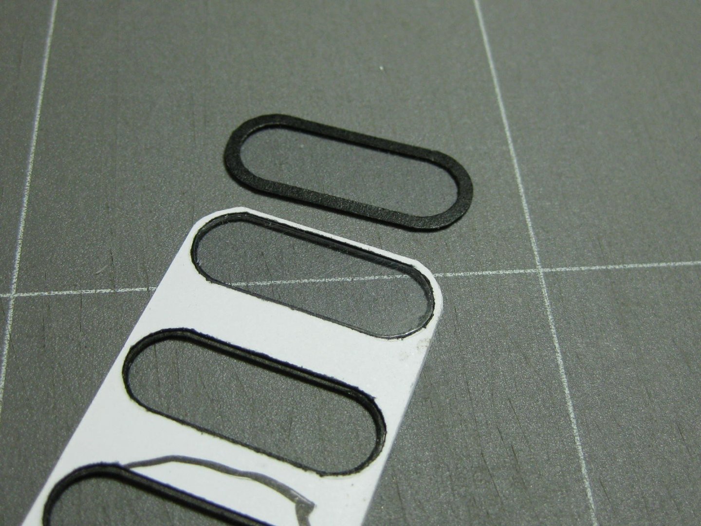
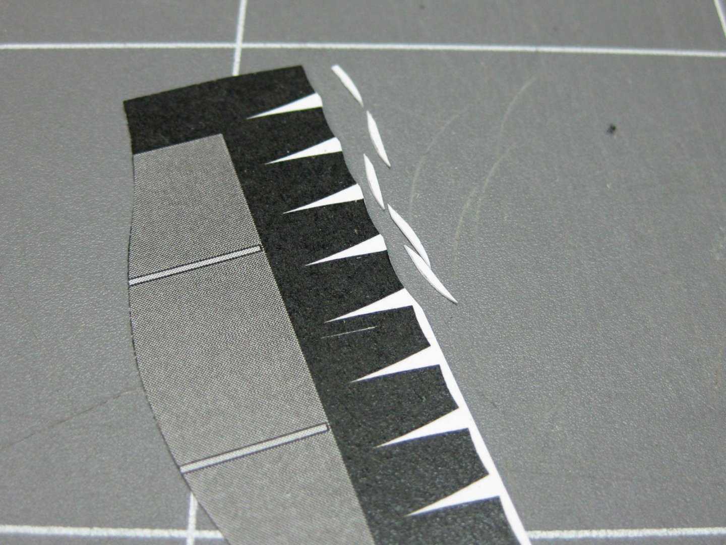
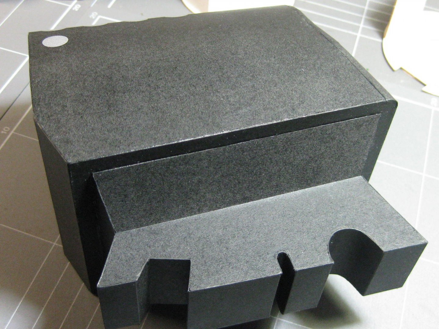
James, I think it might be just a bit harder to make plastic look like paper . Thank you Chris. A lot depends on how well the publisher has drawn the cut-outs for the petals. Then it comes down to accurate cutting - being a right-hander cutting the left side of the cut-out is easy enough, but it requires a counter-clockwise turn of the wrist to cut the right hand side without leaving an "over-cut". I colour the edges of the cuts before bending into the required shape before gluing. On larger bends some extra support under the skin is usually also required. I finish off by running a light-grade sanding stick over the join and re-touching the colour if needed. The fireman's and engineer's control area of the cabin. Lots of fiddly interesting bits to add here . I started with the firebox door : Next come the gauges - 3 parts for each plus an additional disc to maintain the right thickness : Also two levers and a sliding turnscrew and wheel for the brakes : According to the instructions these two boxes are something to do with a lubricating system (unless it was lost in translation ). A lot of work involved with these, starting with 13 hex-head fittings that have a 0.6mm hole in the middle for the piping. These fittings are only 1mm wide and took a bit of thought as to their manufacturing process. I started by spraying the sheet with gloss clear to give them some additional strength, punching the holes in them while they were all still on the sheet and then proceeding as usual for a hex-head bolt : The pipes are 0.5mm black powdercoated copper wire used for bead making. I'm not sure about where they go after turning the corner, nothing shown in the instructions so this was my take on it : A few more pieces will be added to this area later in the build. Danny


- 150 replies
-
- 13
-
-
All good now, I fixed it. Just a slip of the pen originally . "what did they supply for the plumbing.........your use of the metal rod is a better alternative" They don't supply anything for plumbing, but metal rod or wire is specified in the instructions. Most of these have a diagram you can follow, plus the size of wire. Thanks everyone else for the comments. This is a most enjoyable model to build from a good publisher. The kit has a few small problems, but which kit doesn't? Nothing I haven't been able to work around. Danny
-
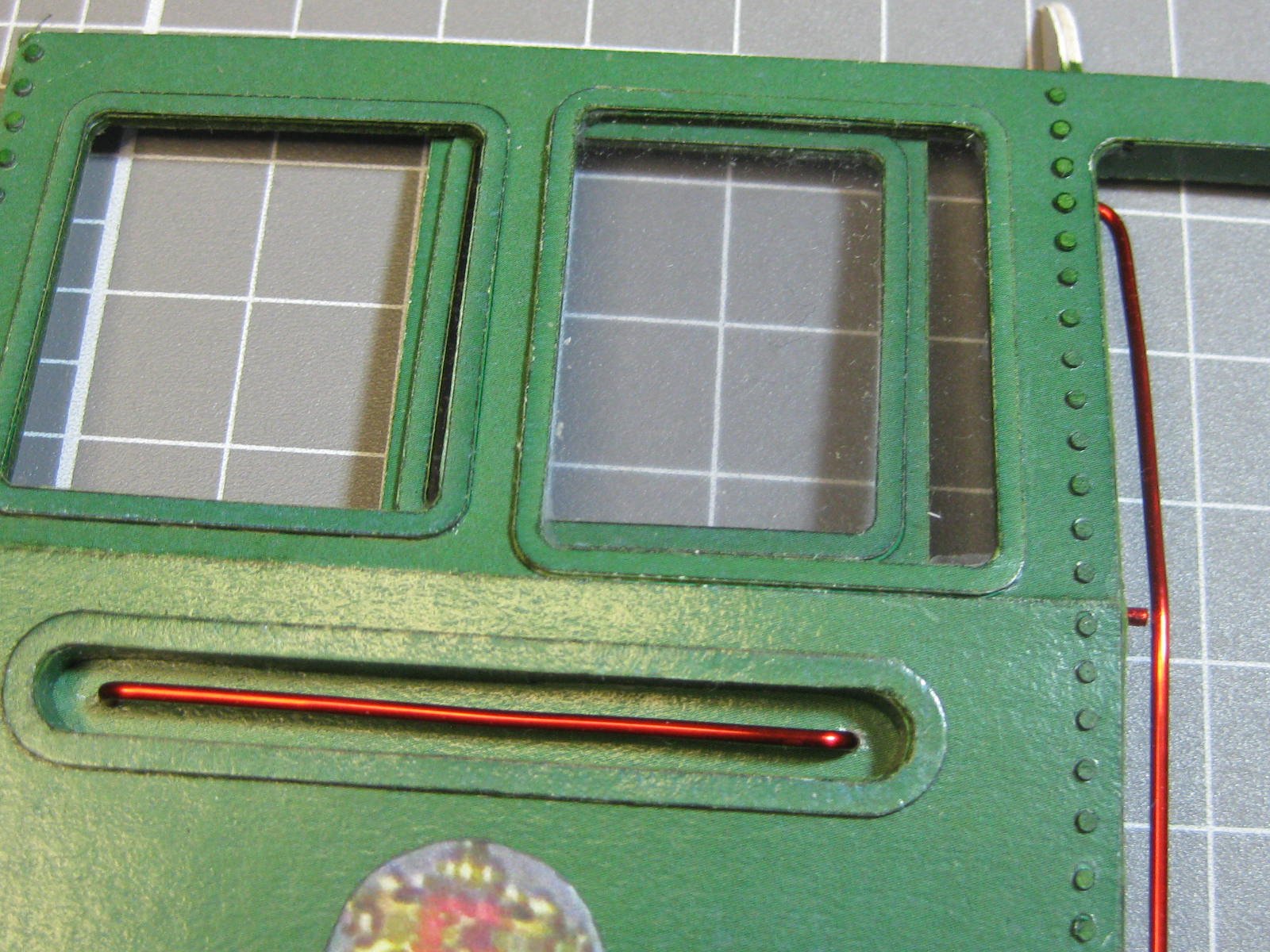
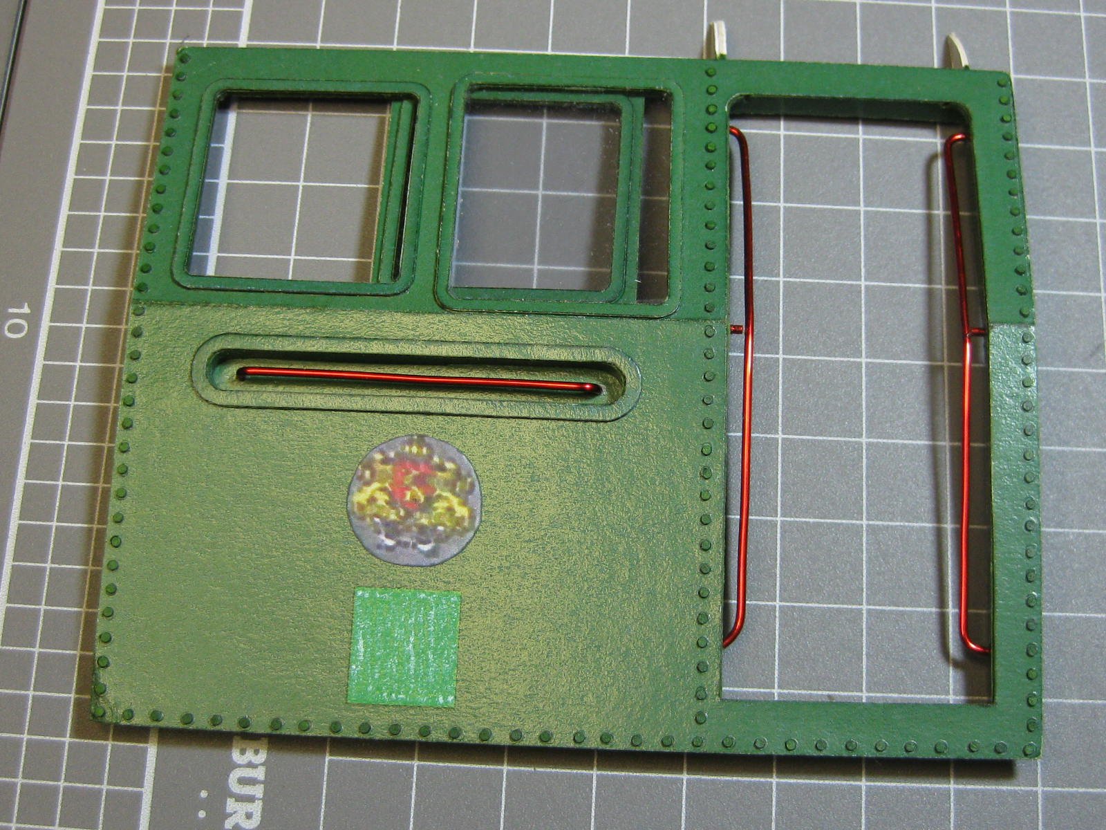
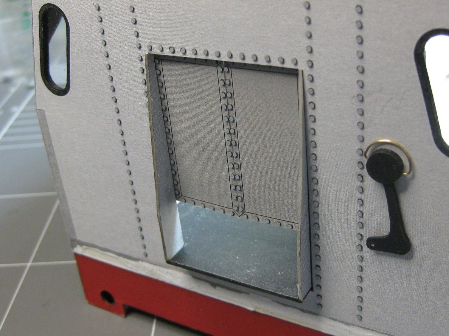
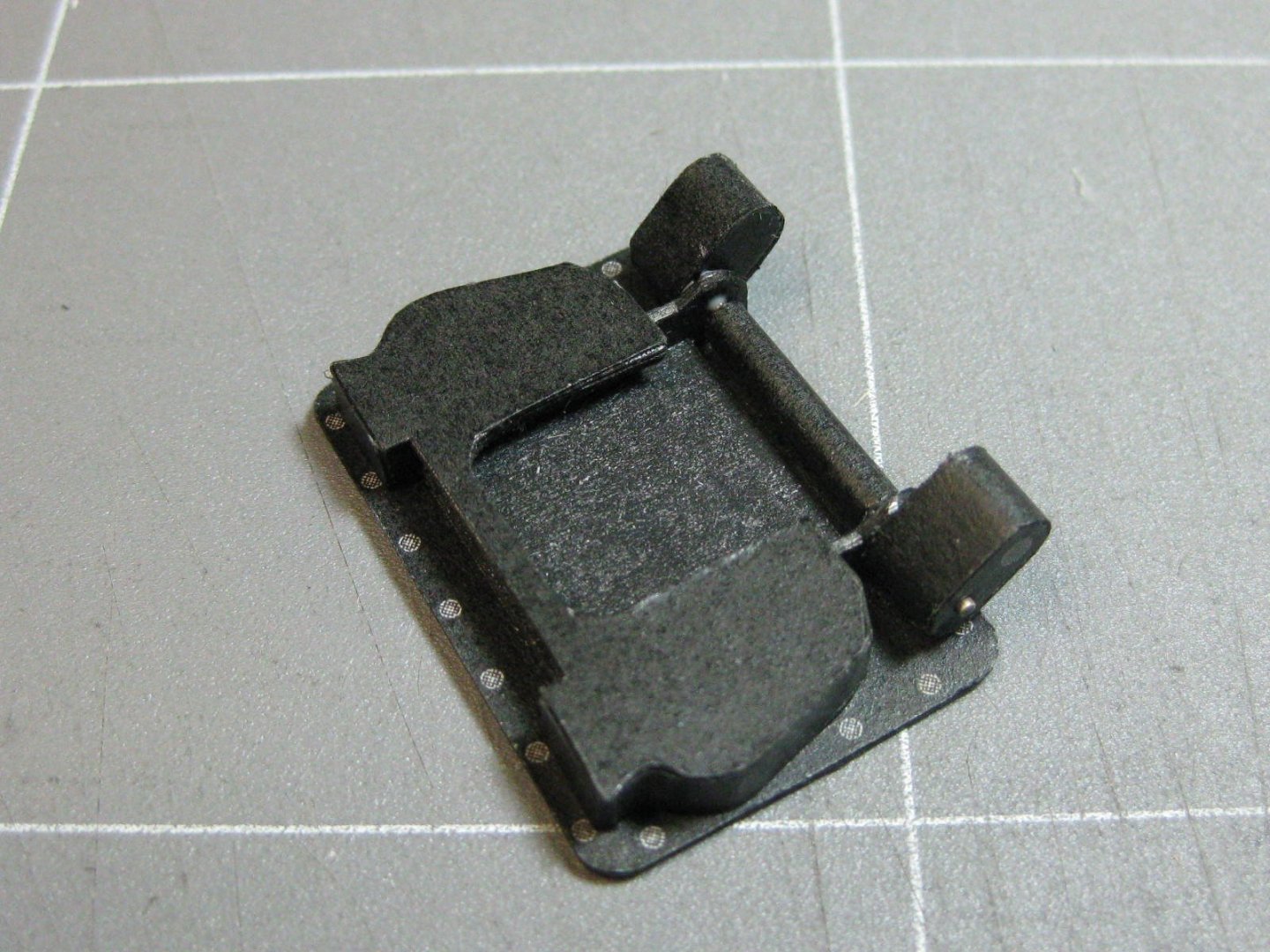
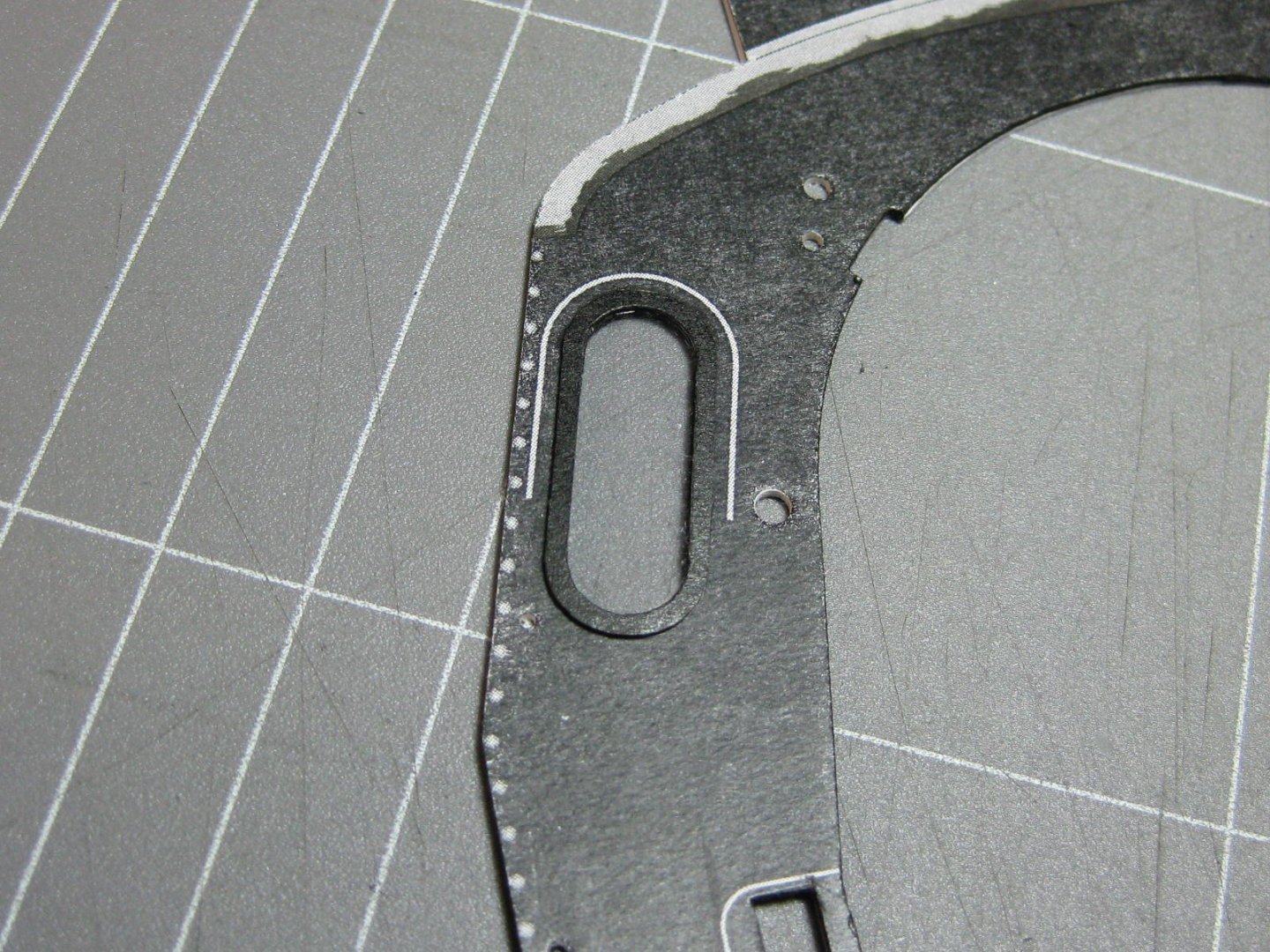
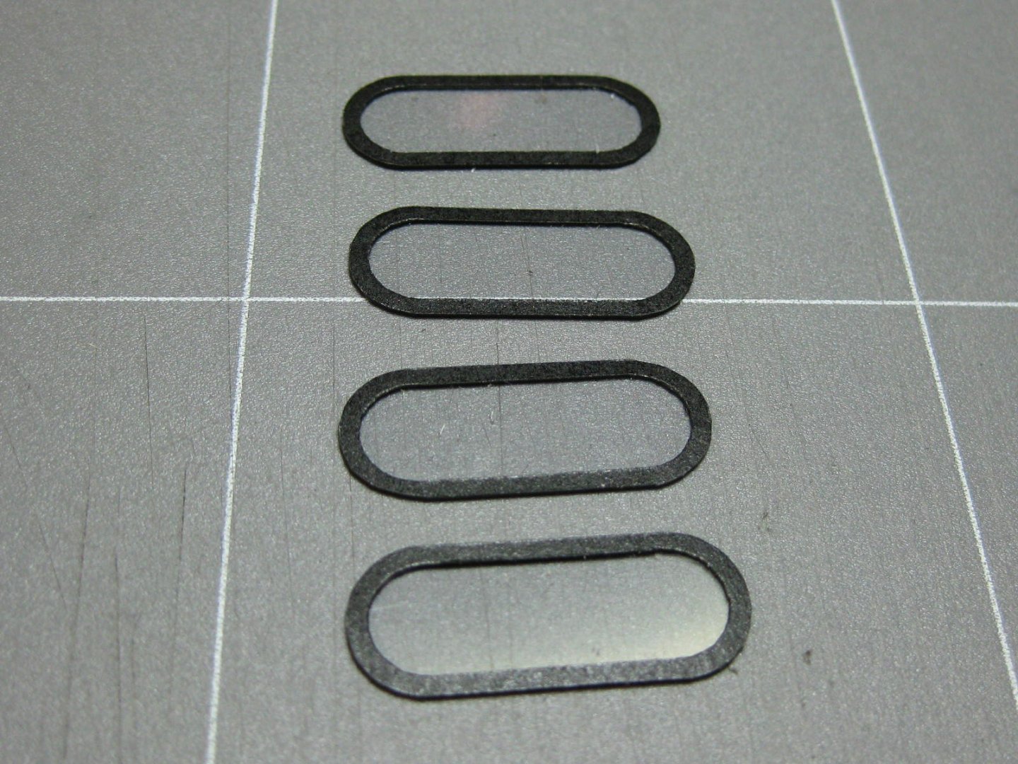
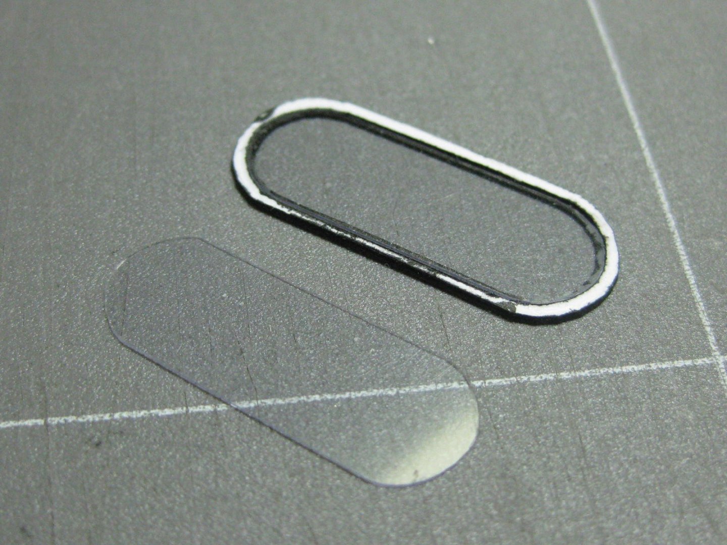
I've just spent about 4 hours cutting and fitting four windows. I've sandwiched some 0.25mm clear acrylic between the outer frame and the wall by cutting the hole in the lamination piece 0.5mm larger than the skin piece. They turned out perfect : Danny
- 150 replies
-
- 20
-
-
Thanks Caroline . Now I could fit the two forward sections of the boilers together. The join is behind one of the black "real" joining strips. They lined up perfectly : The next step will be the start of the cabin. Danny

- 150 replies
-
- 20
-
-
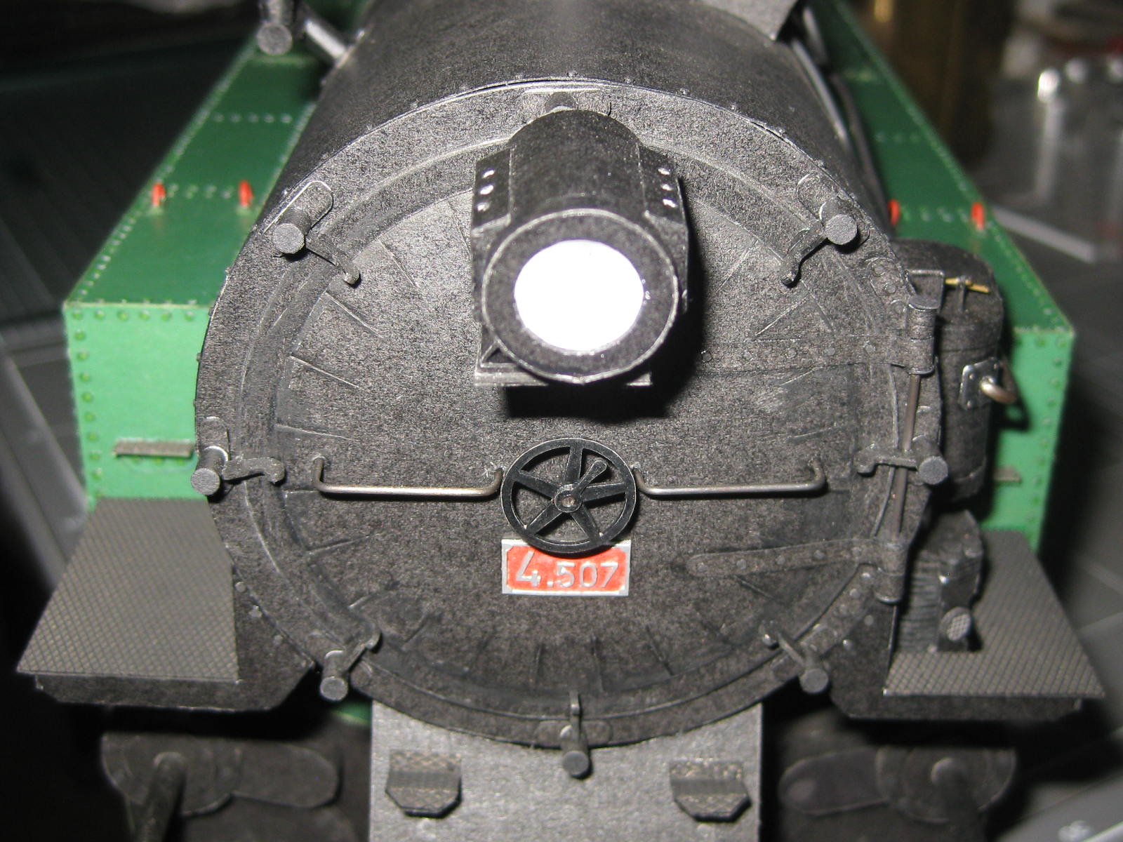
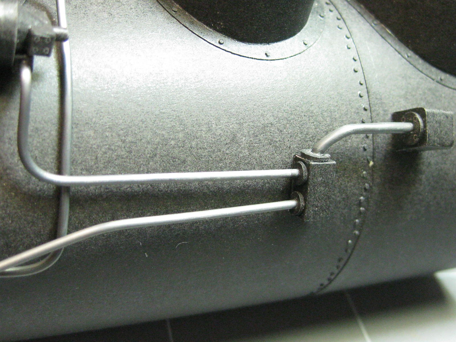
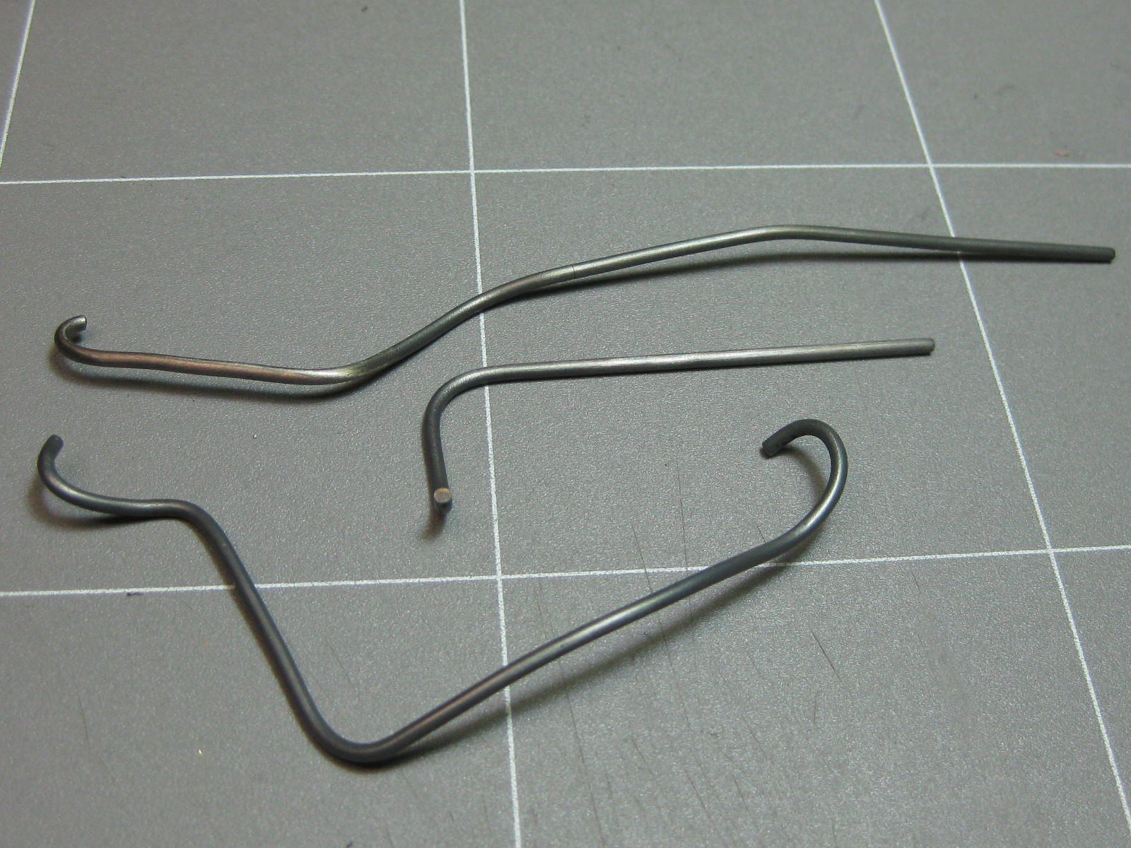
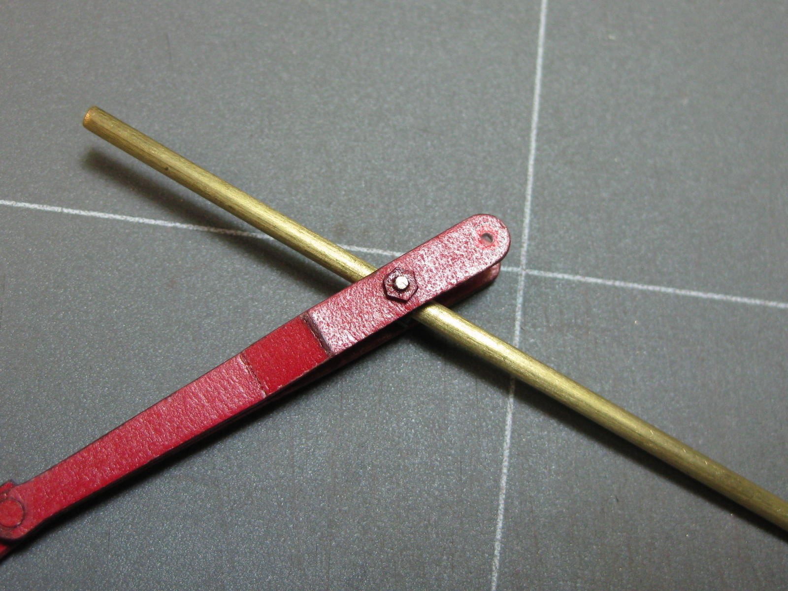
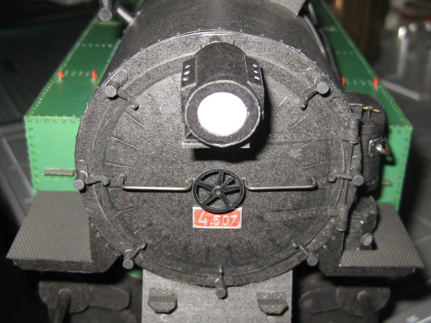
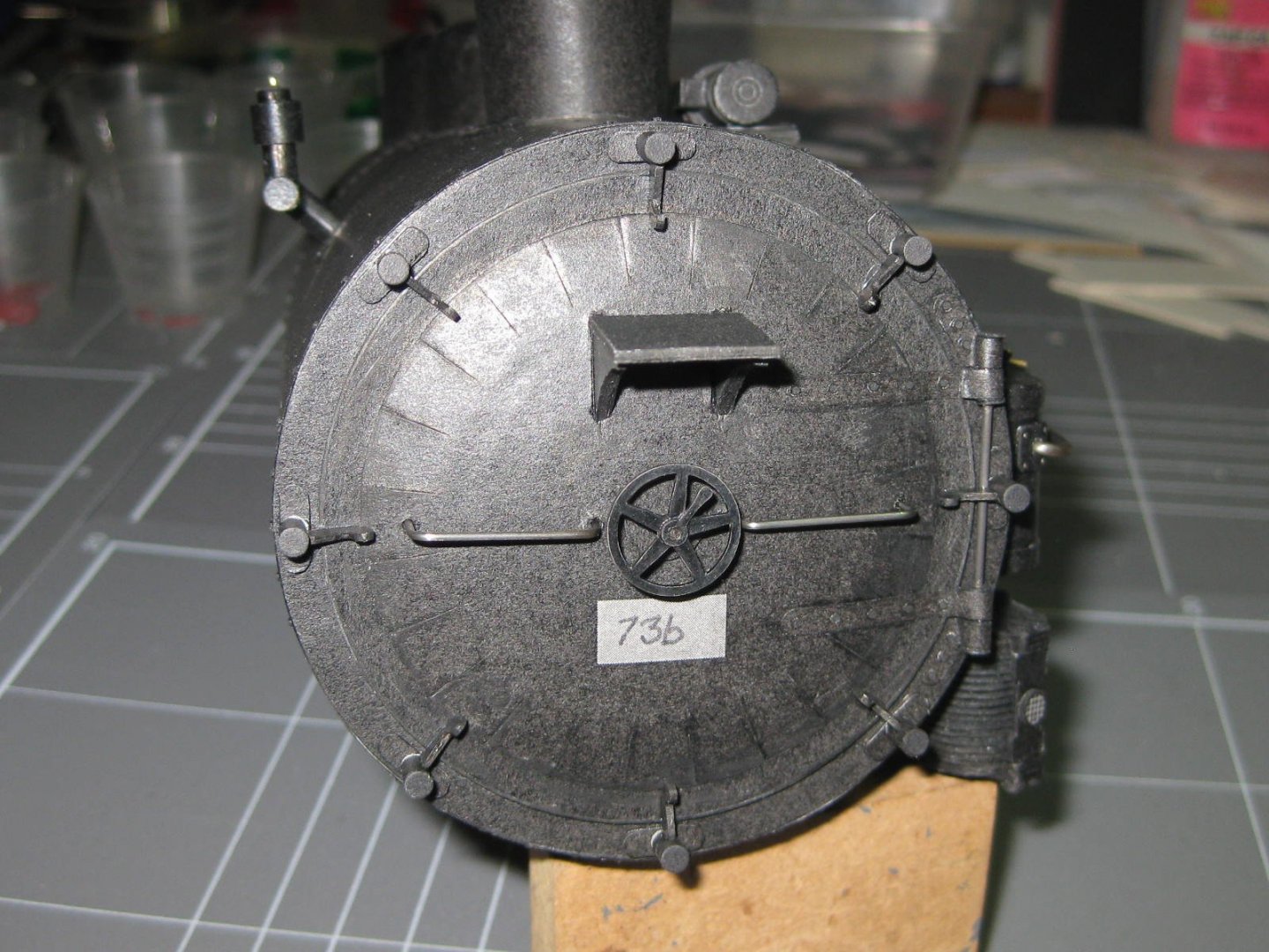
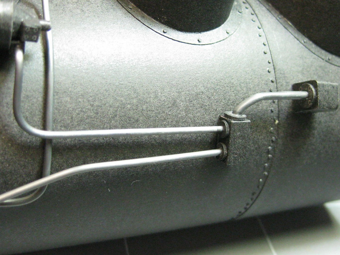
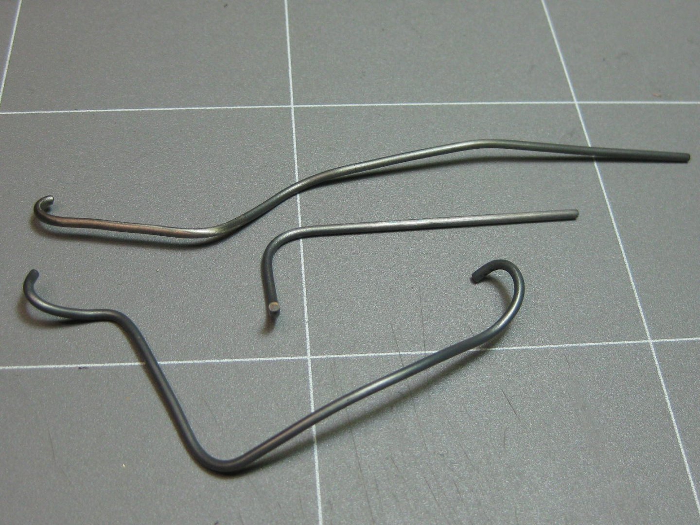
And thank you David and Phil . The plumbing is made from 3 sizes of brass rod - 2.0mm, 1.5mm and 1.0mm. I annealed it before attempting to make the bends. The most complex bend took me over an hour to get it ready for blackening with Birchwood-Casey Brass Black. I installed these pieces now before fitting the sections of boiler together : Some type of safety blow-off valve perhaps ? Also before fitting the boiler sections together I finished off as much of the front plate as I could : Danny

- 150 replies
-
- 18
-
-
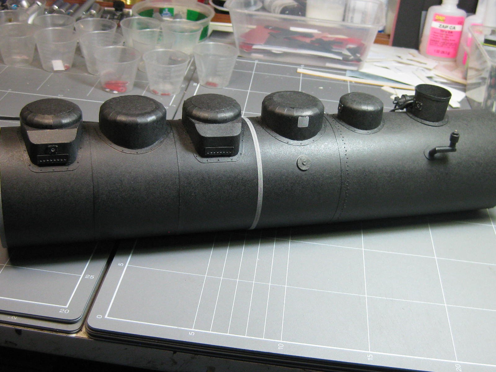
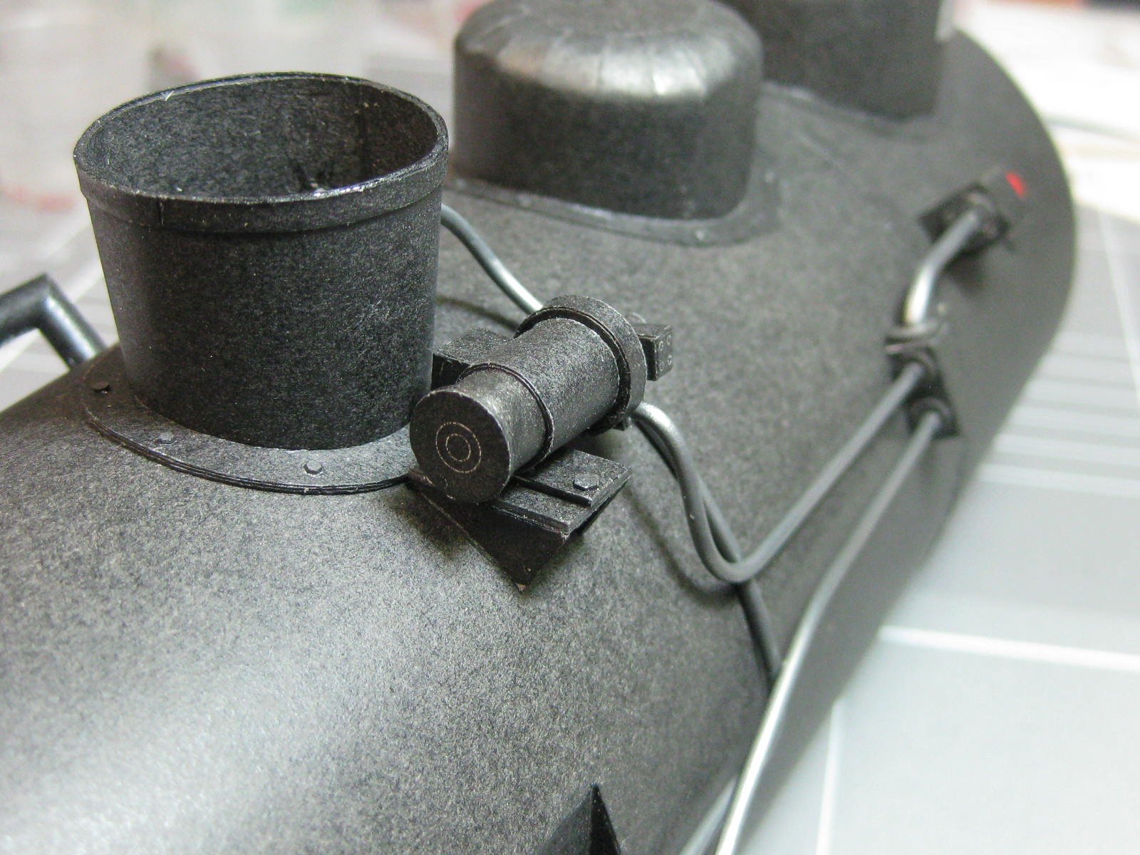
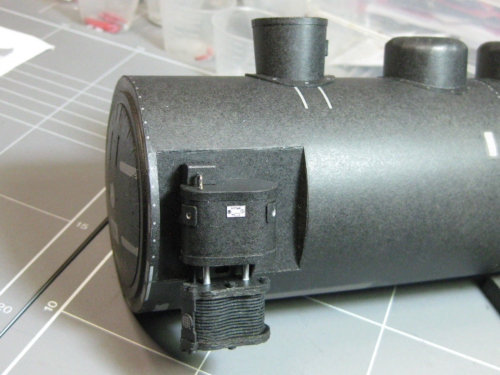
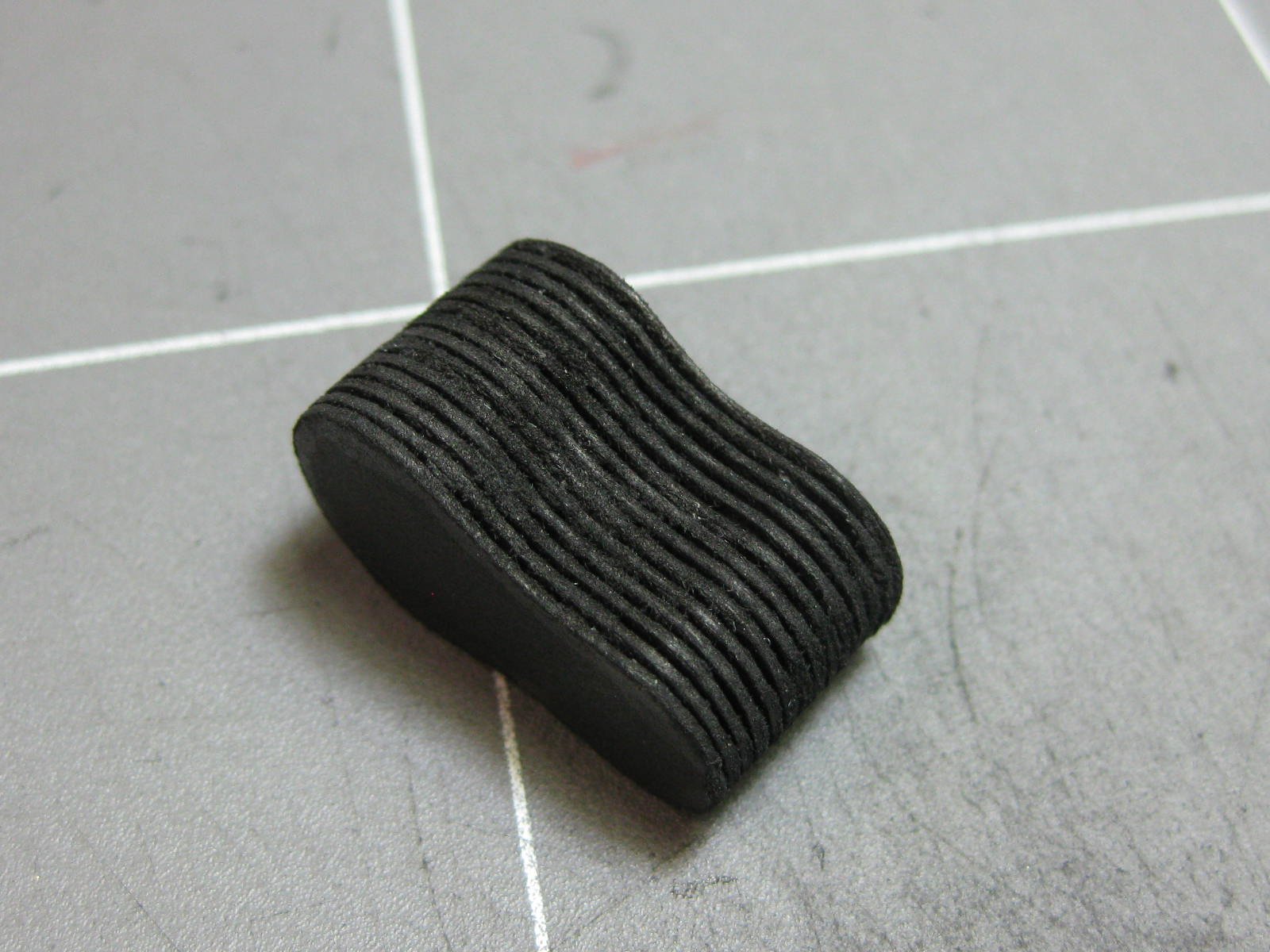
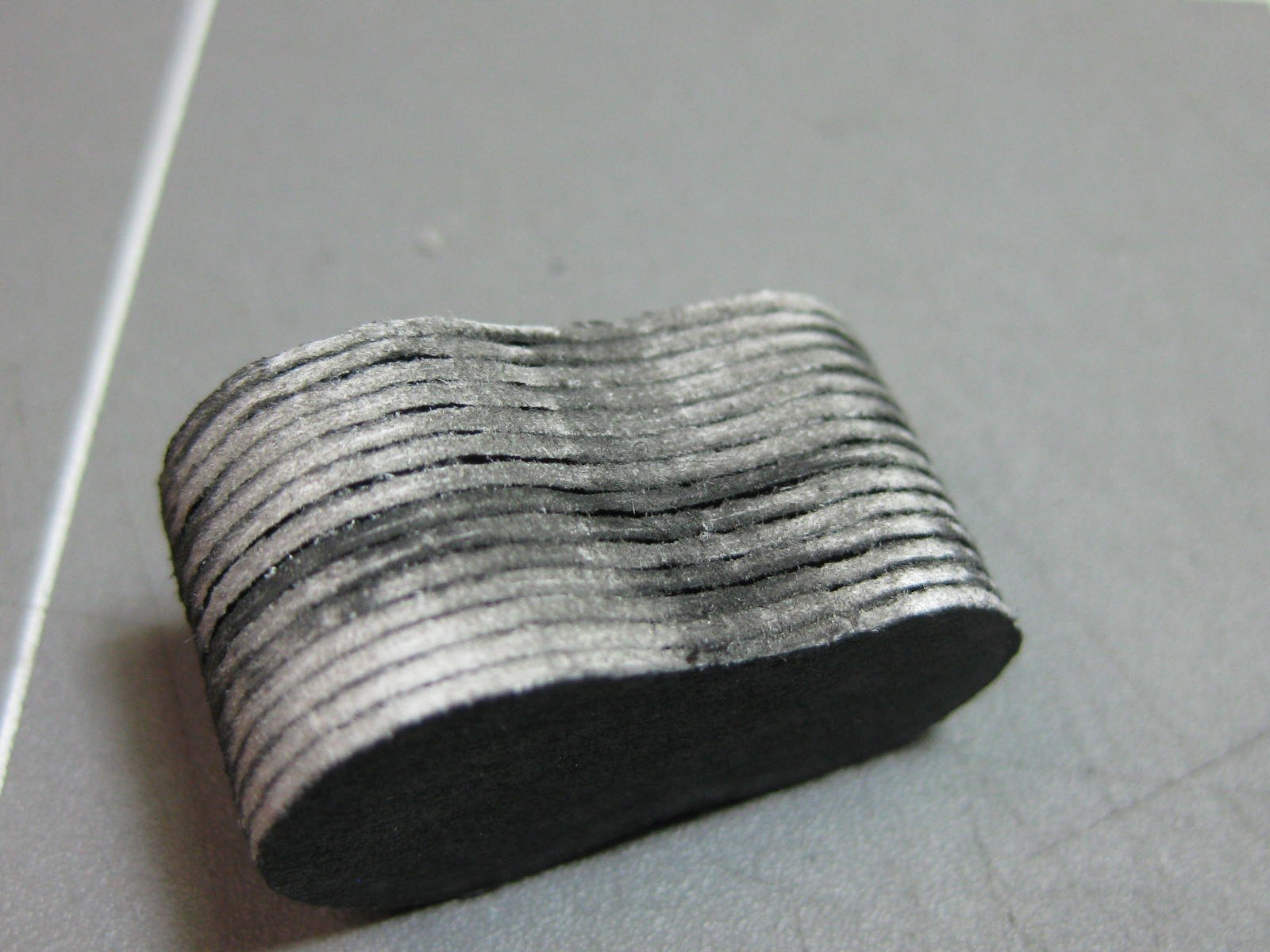
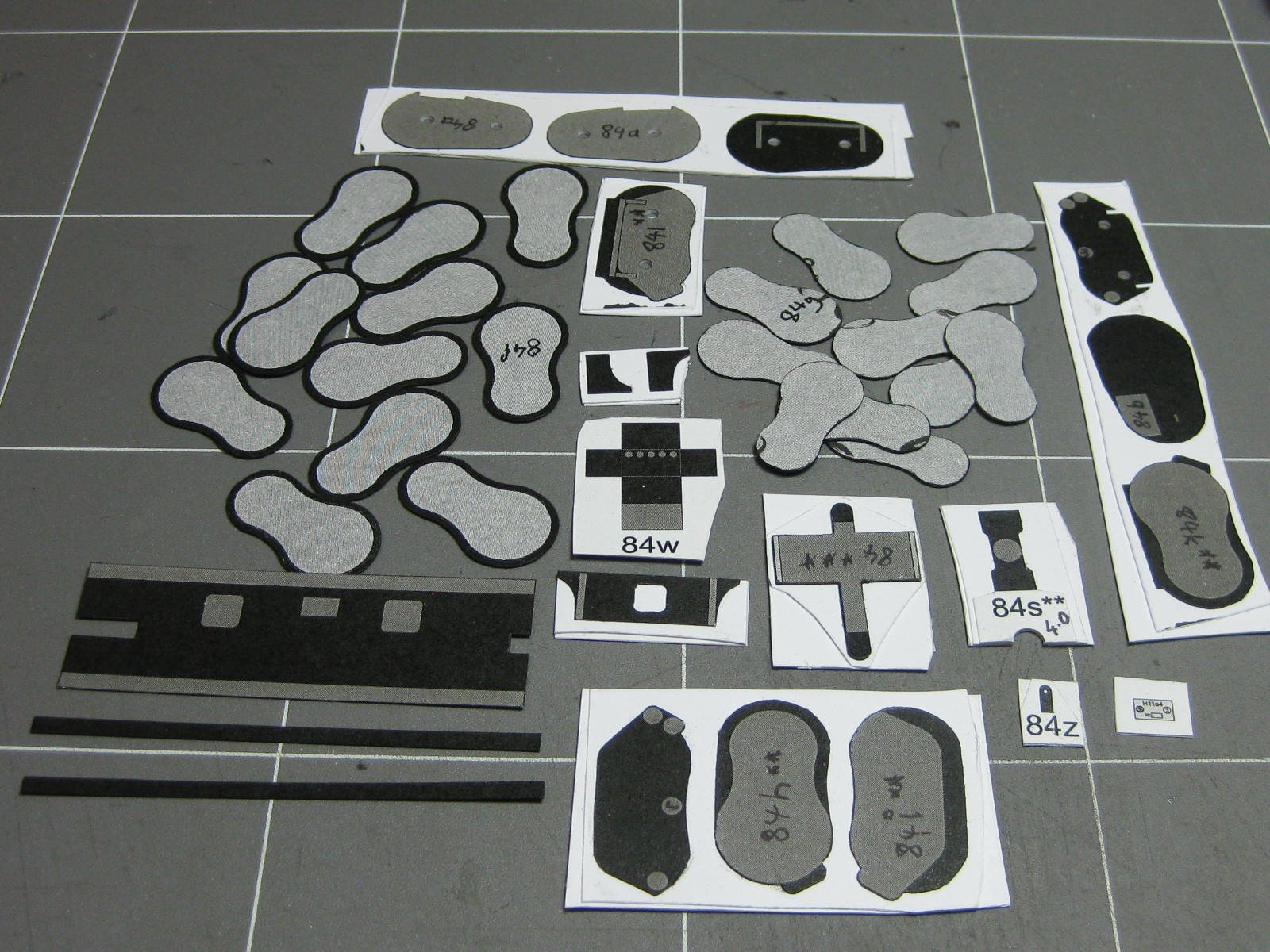
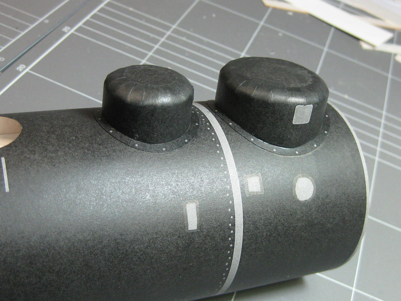
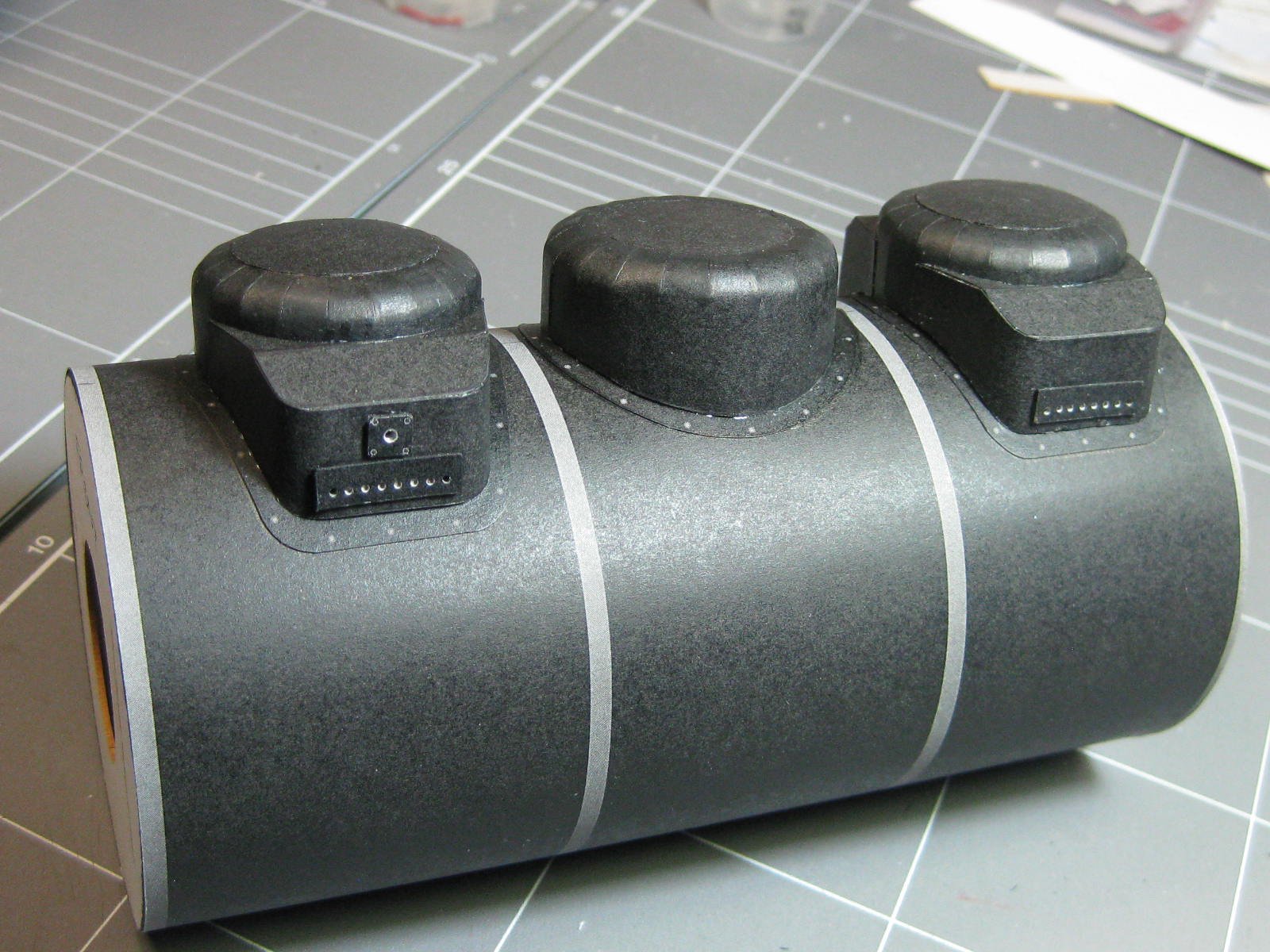
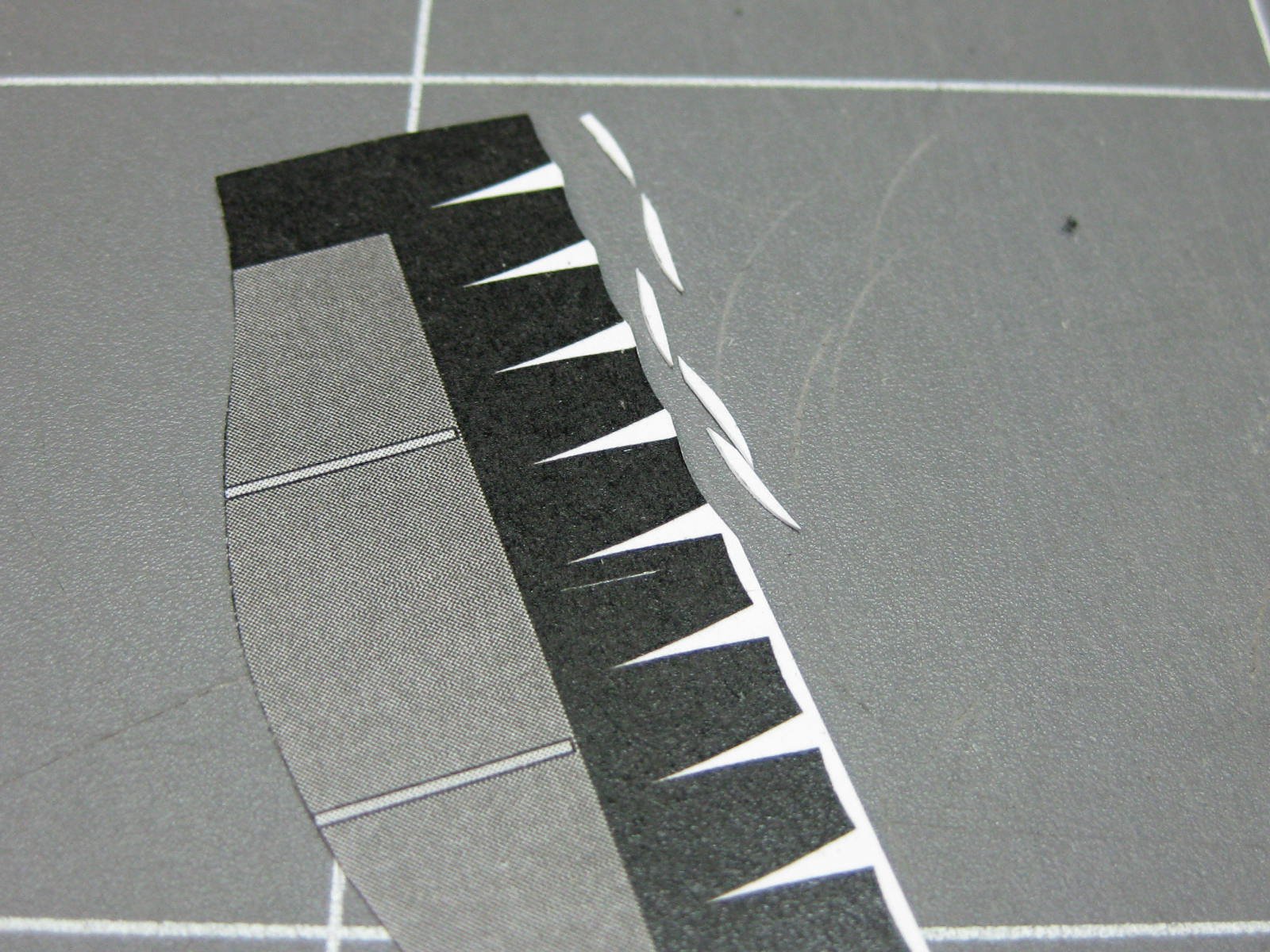
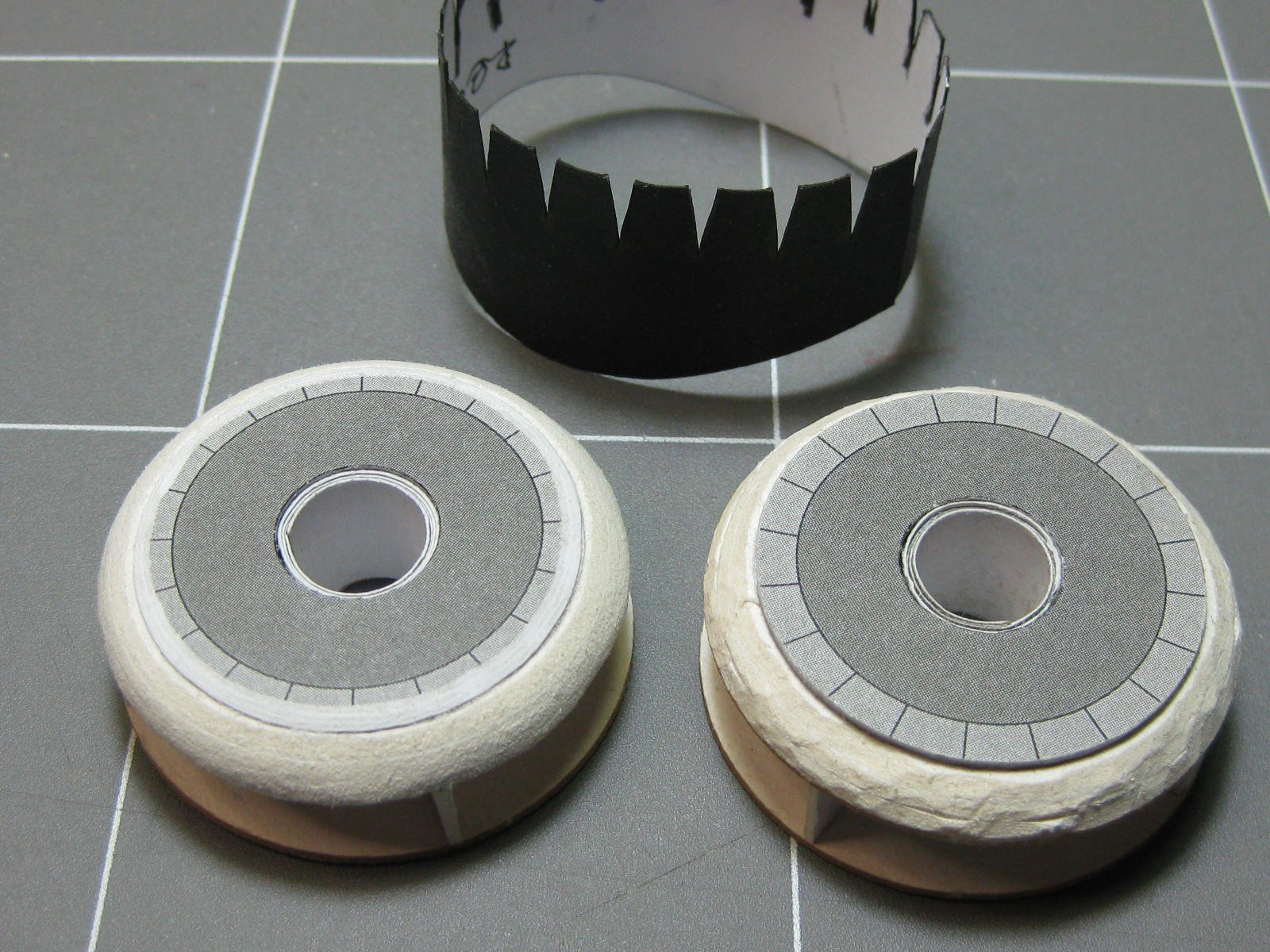
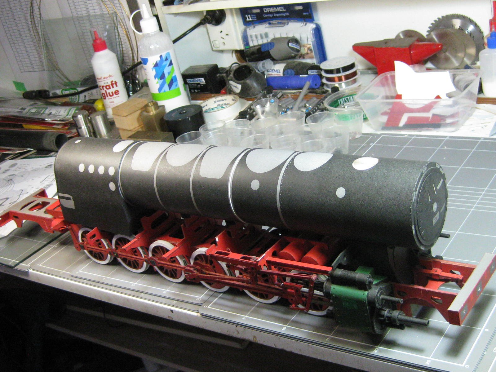
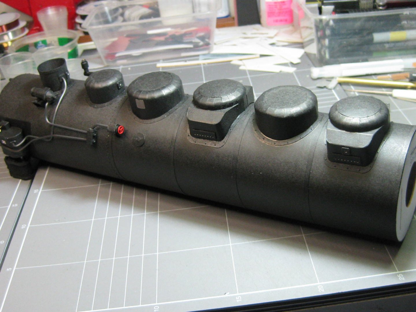
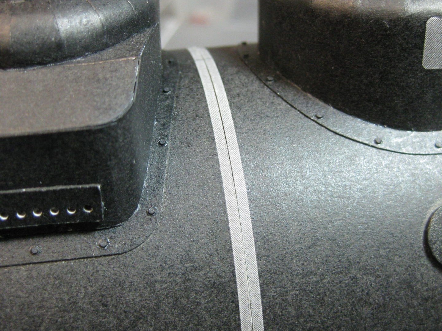
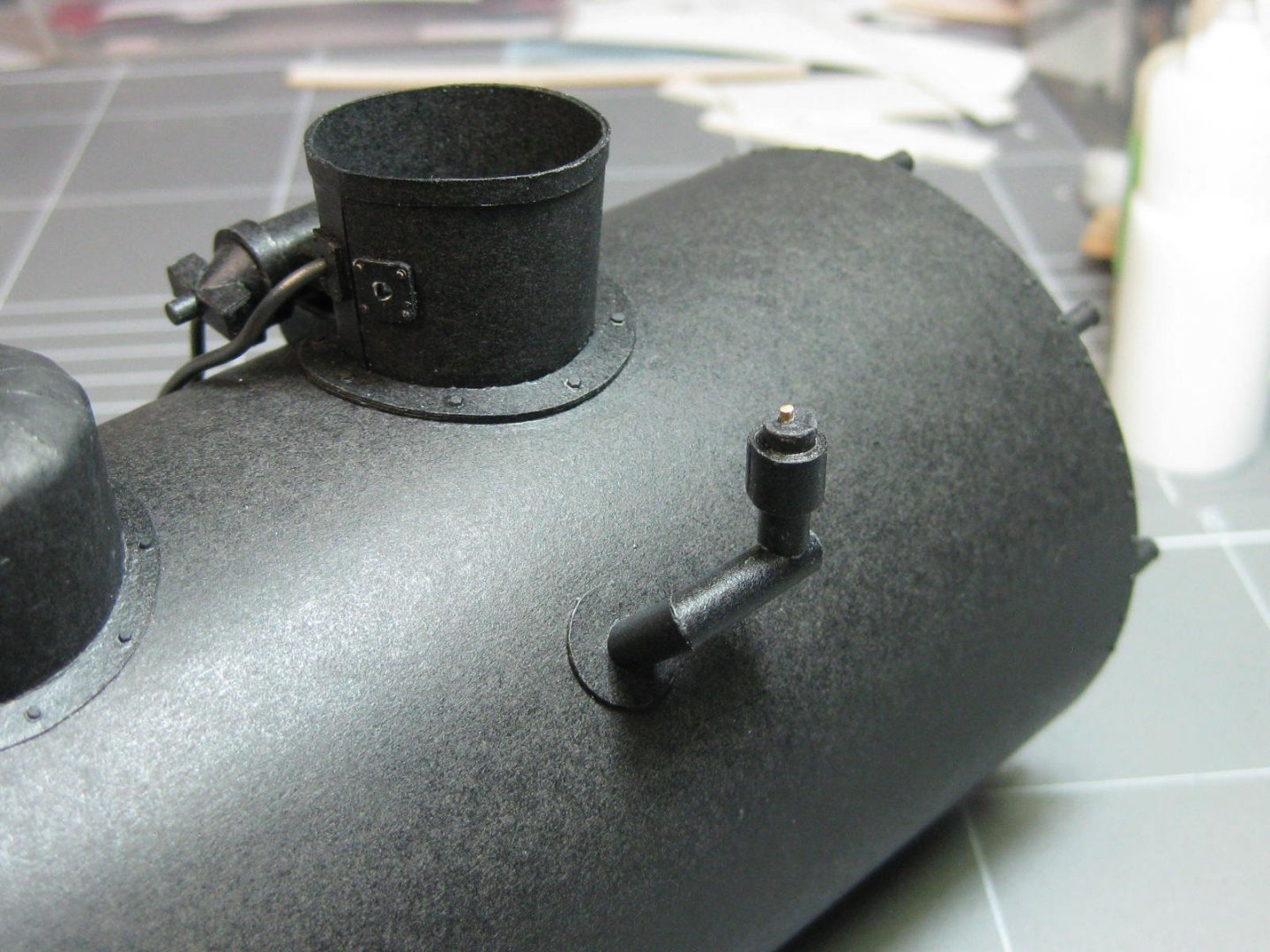
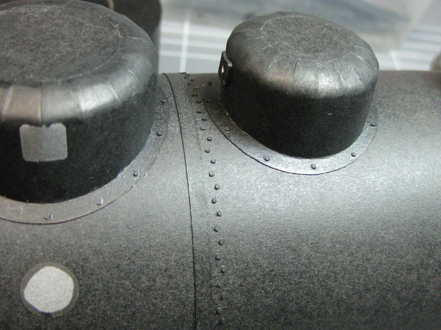
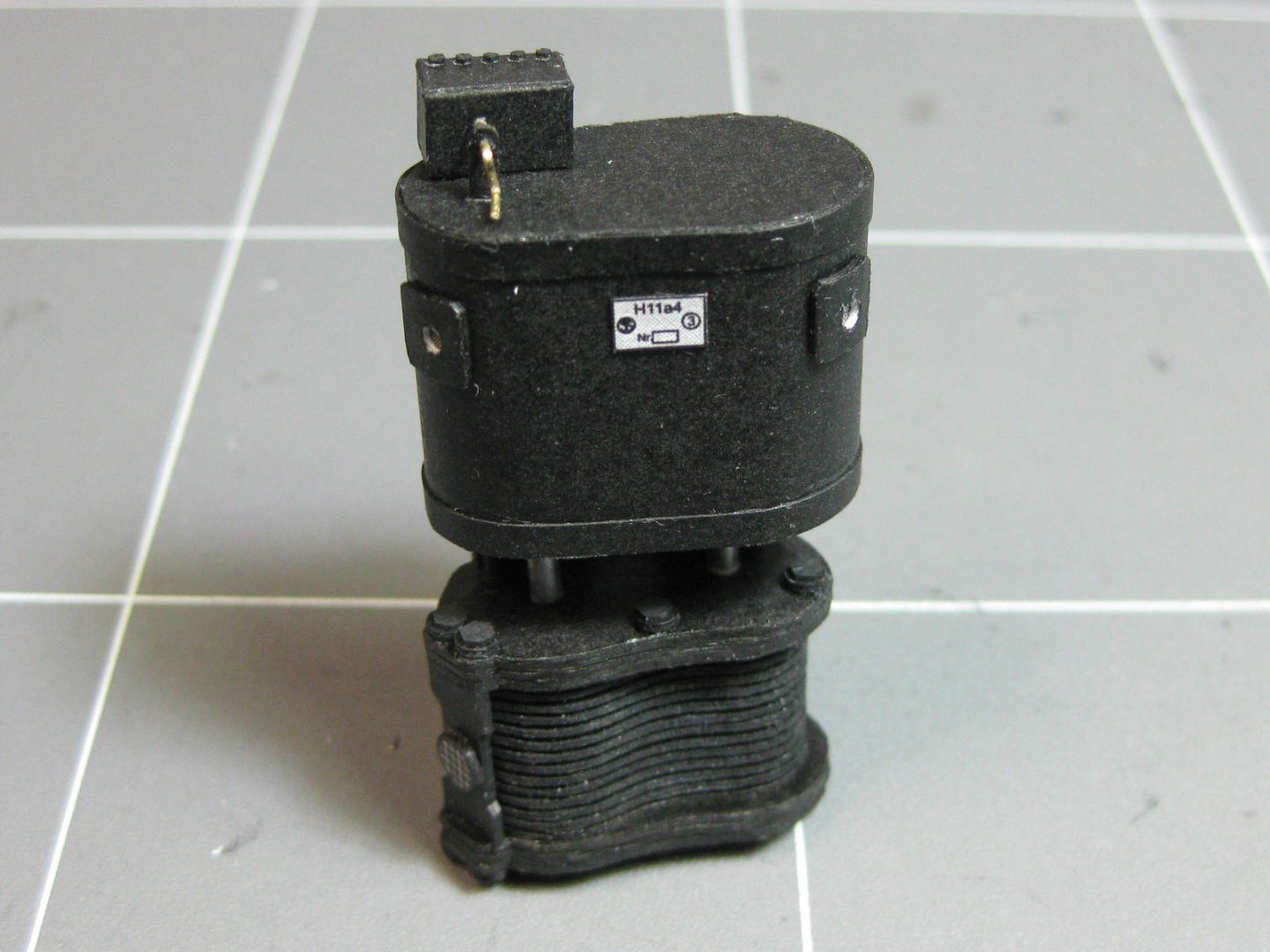
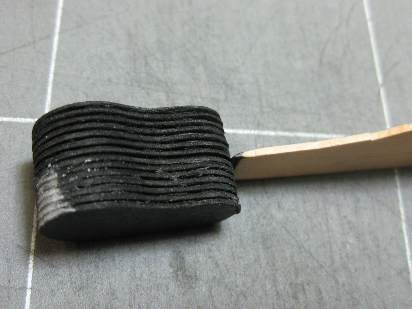
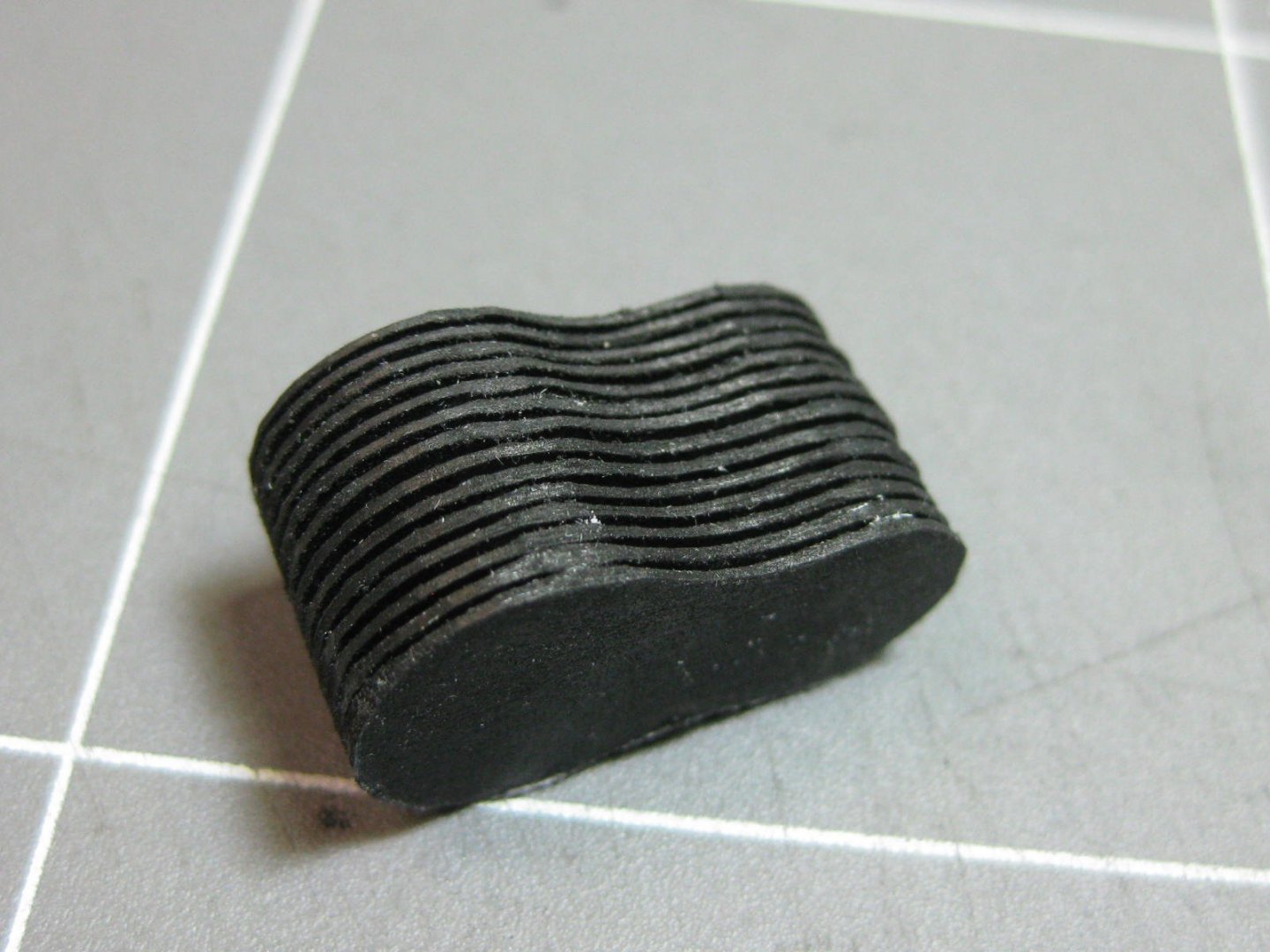
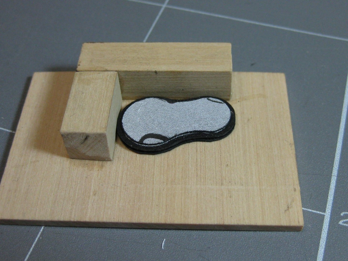
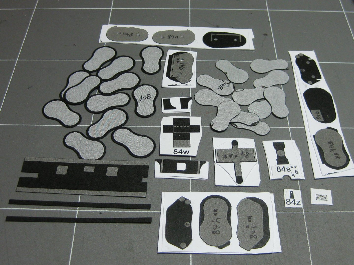
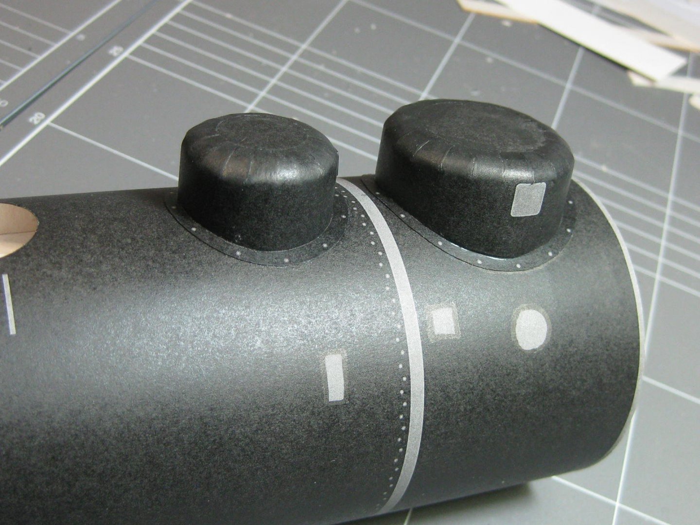
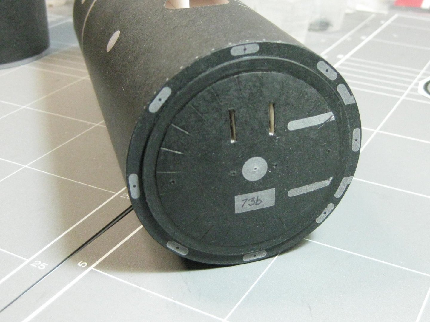
Thanks for dropping in again guys . "It might be possible with a bit of trickery to make the model work on air." Michael, none of my models are "powered" by anything more than my hand or fingers. I'm not about to start now . Electric (battery) power would be the only option I would consider, but I'm way past the stage of installing anything like that. The sandboxes and safety valves on top of the boilers. These have domed tops which came out well thanks in part to the preparation work I did. The rounded part of the extra card infill was first cut almost to shape with a scalpel (right) before final sanding with a sanding stick (left) : At a quick glance the ends of the tabs on the skins looked straight - they weren't : The boxes fitted to the two boiler sections : This next piece - the compressor - took me two full days to make. There are 28 separate sections in the fins alone : A jig made alignment a little easier : The glued fin section before any final finishing : Some of the fins were very slightly larger or smaller than others (I'm talking 0.2mm at worst) but the differences were noticeable so I cut and filed them all to the same size : It still needed a bit of cleaning up with a tapered piece of wood : The finished compressor : The start of thousands of 0.8mm rivets : Danny


- 150 replies
-
- 18
-
-
Take a look at THESE Pitt Artist Pens. I use them in my paper modeling and find them quite good. No bleeding whatsoever and they come in a large range of colours that can be "adjusted" to a certain degree by using one colour over another. Also come in various sizes of nib from extra-fine to Brush size, but only in a limited range of colours for some sizes. Danny
-
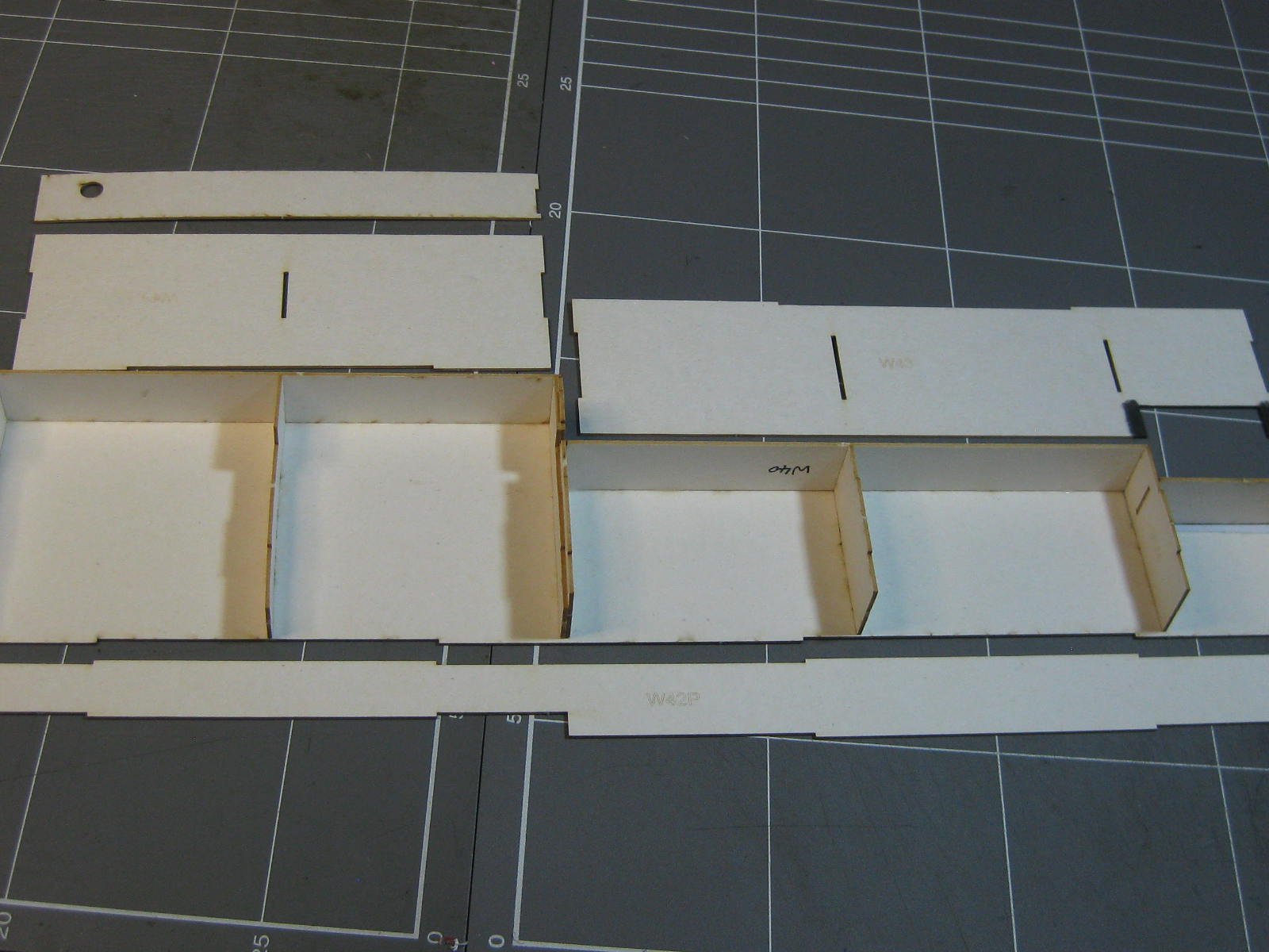
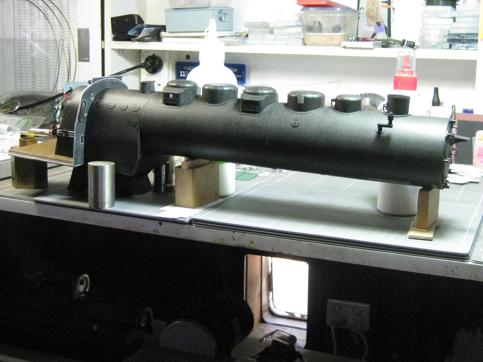
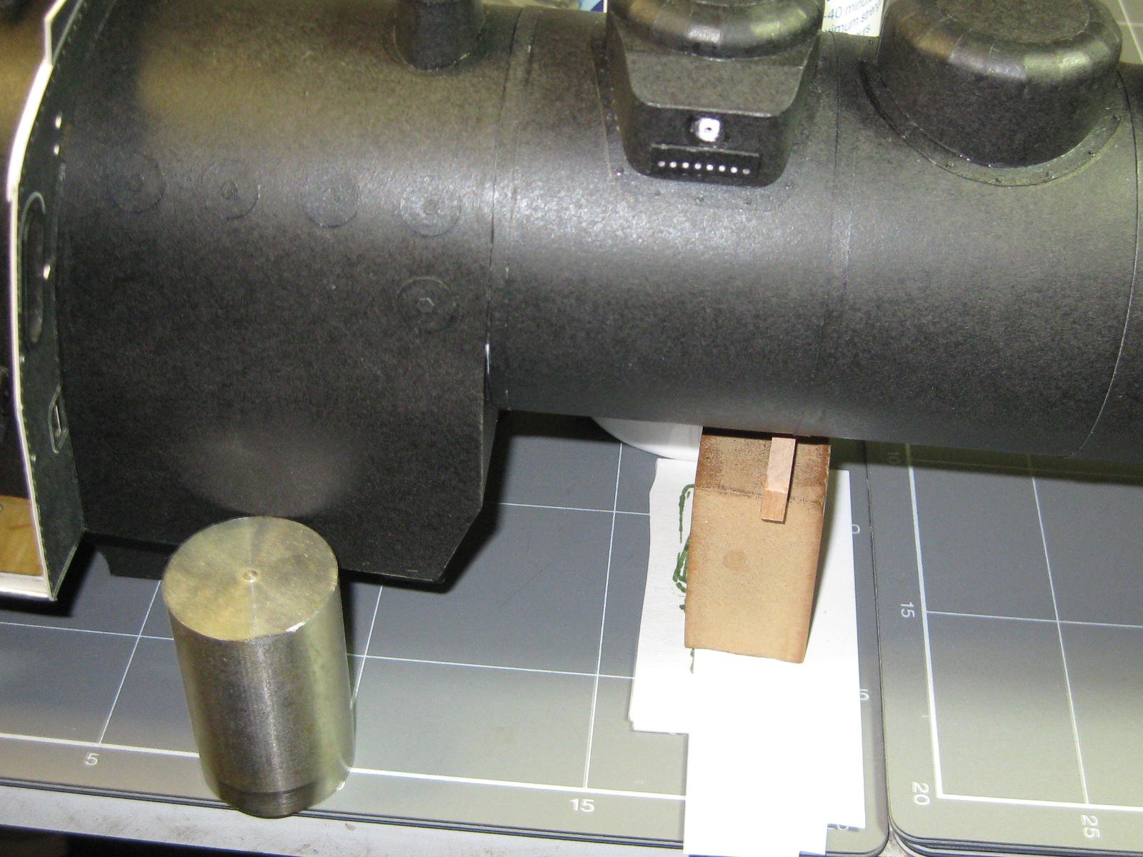
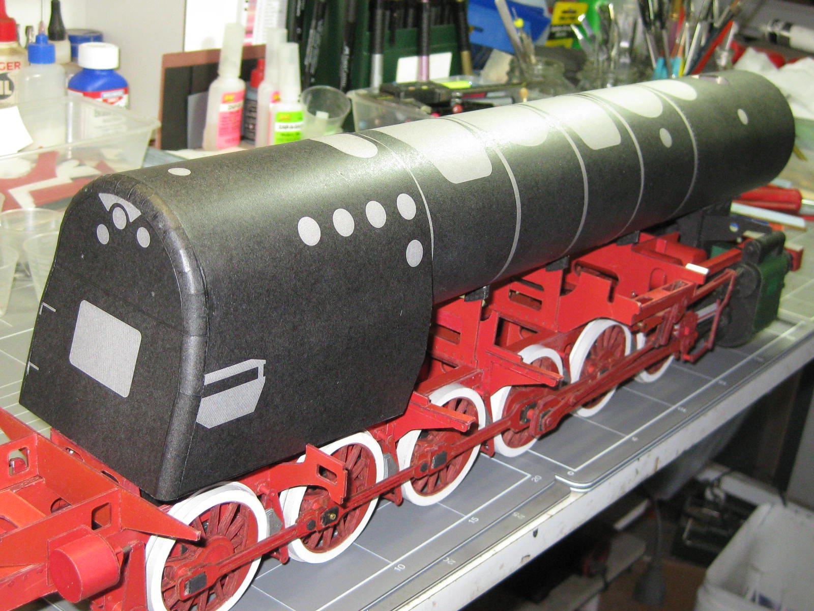
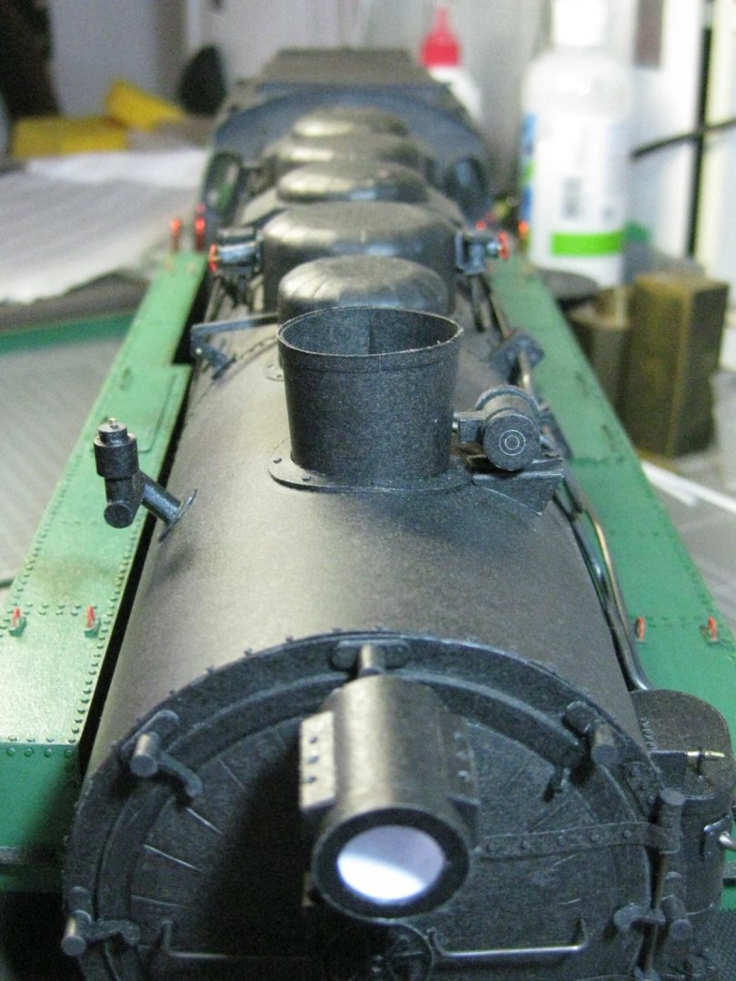
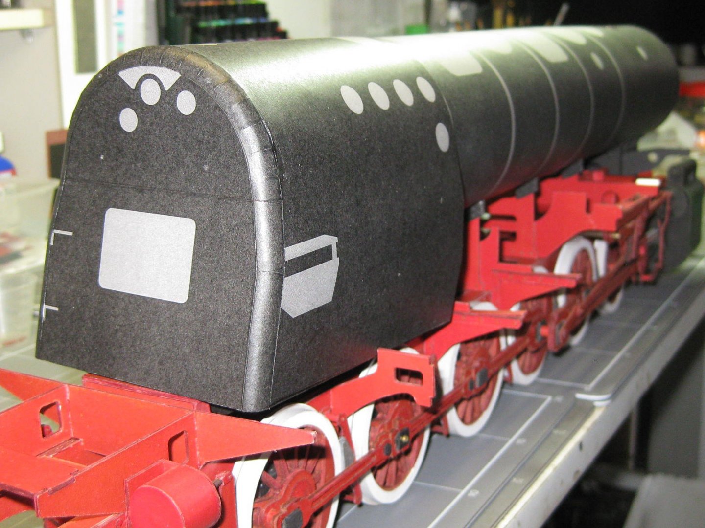
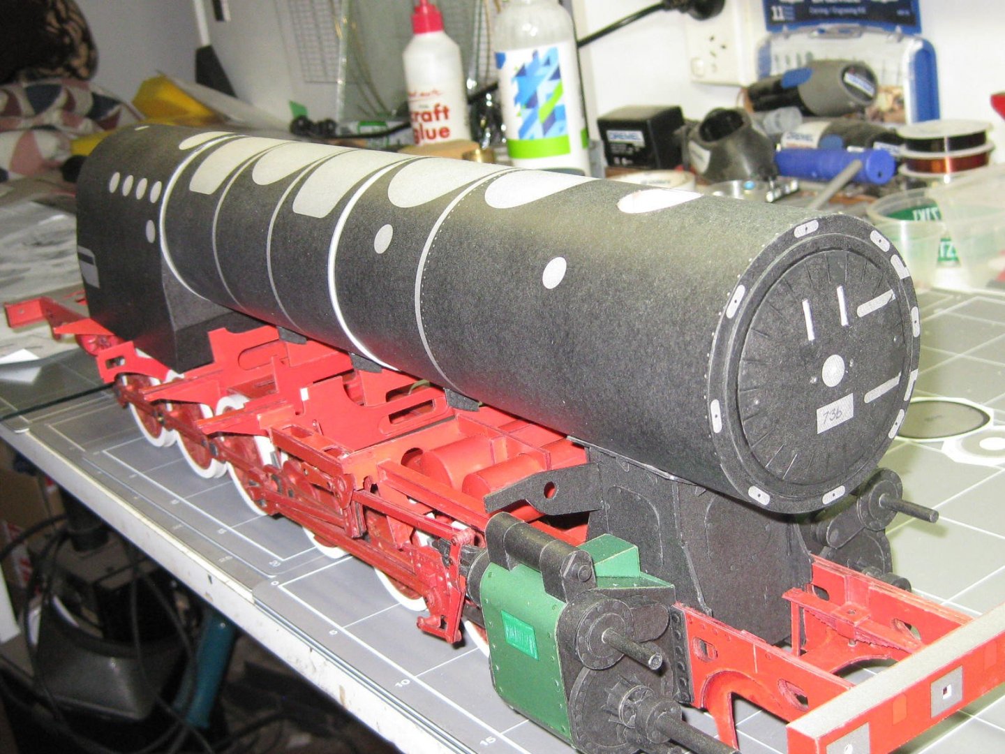
Next job was the two boilers. It only took me a day and a half to make them both, and the finished result was really good - some of the best pieces I've ever made . Once again I added extra card strips to prevent any crushing - it's a lot easier to crush a beer can barehanded than to do the same to these : Once the frames were finished I rolled and glued the skins. These were then slipped over the frames from one end and glued to them : The front of the boiler has a domed end. I sanded the shape into some extra card pieces before skinning it : I just had to take a couple of pics of my overall progress. The boilers and firebox are only sitting in place, it's a lot easier to add all the extras to them in smaller units : Danny


- 150 replies
-
- 24
-
-
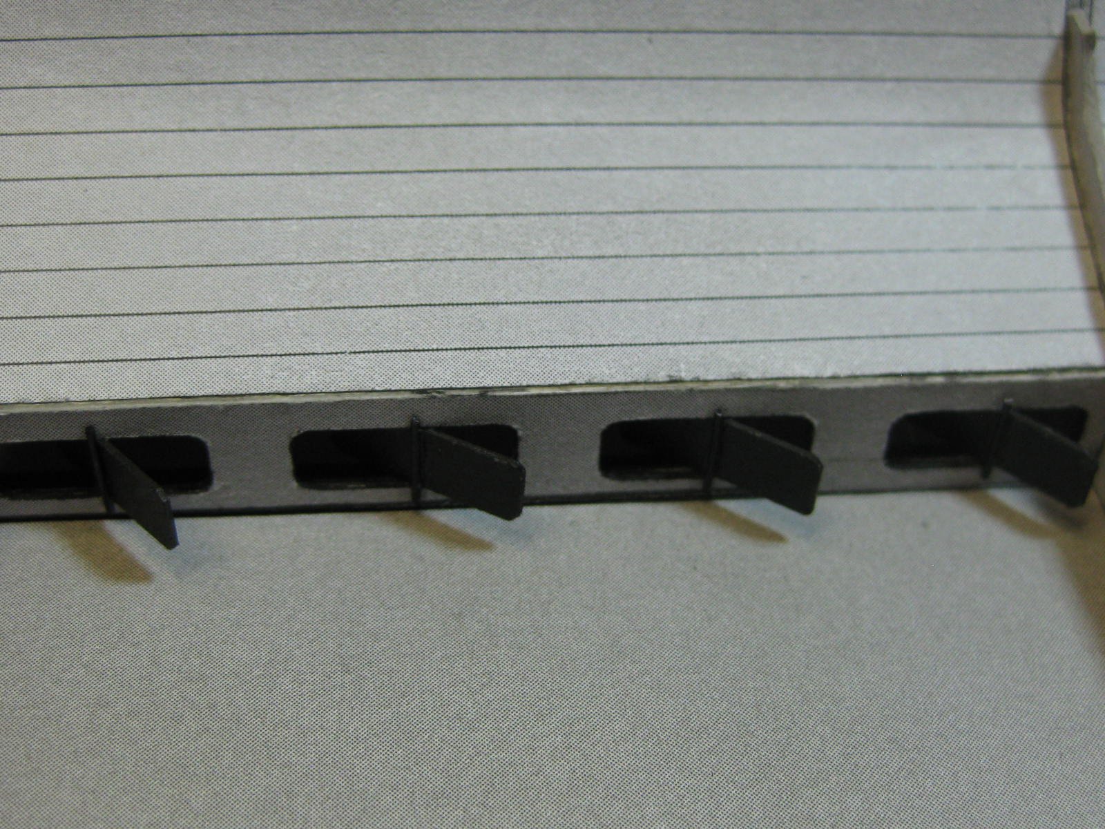
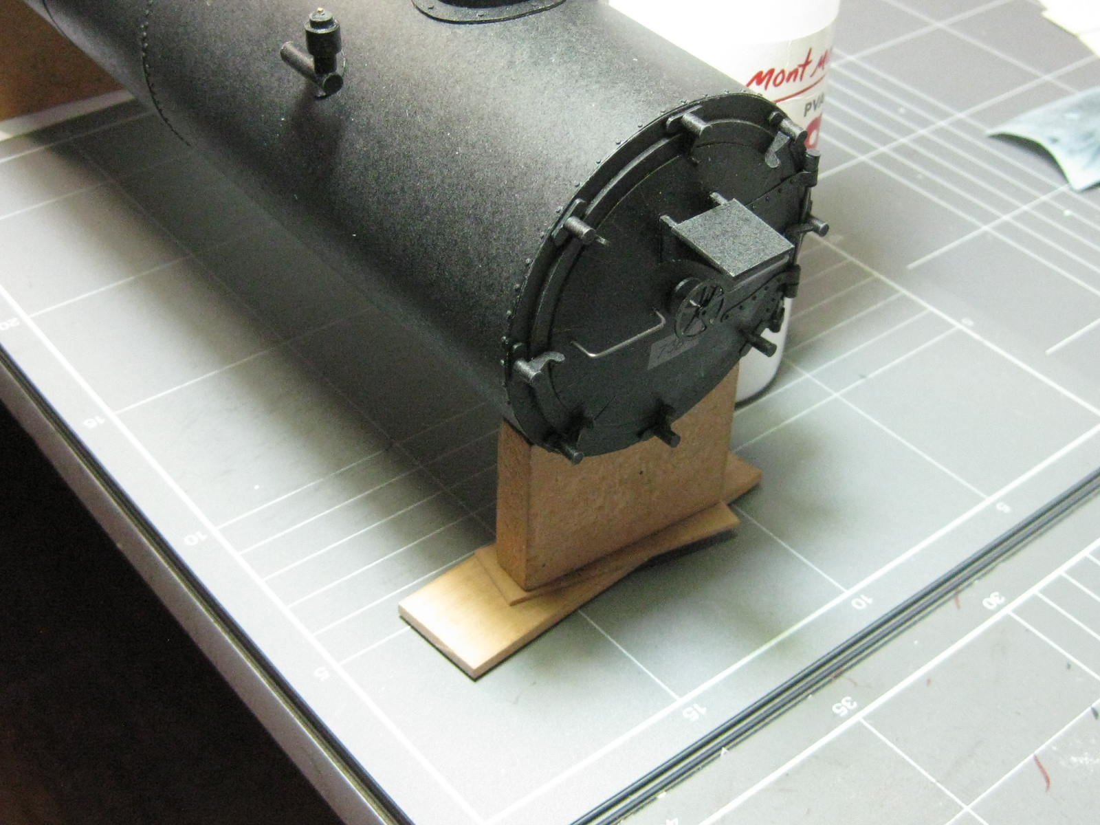
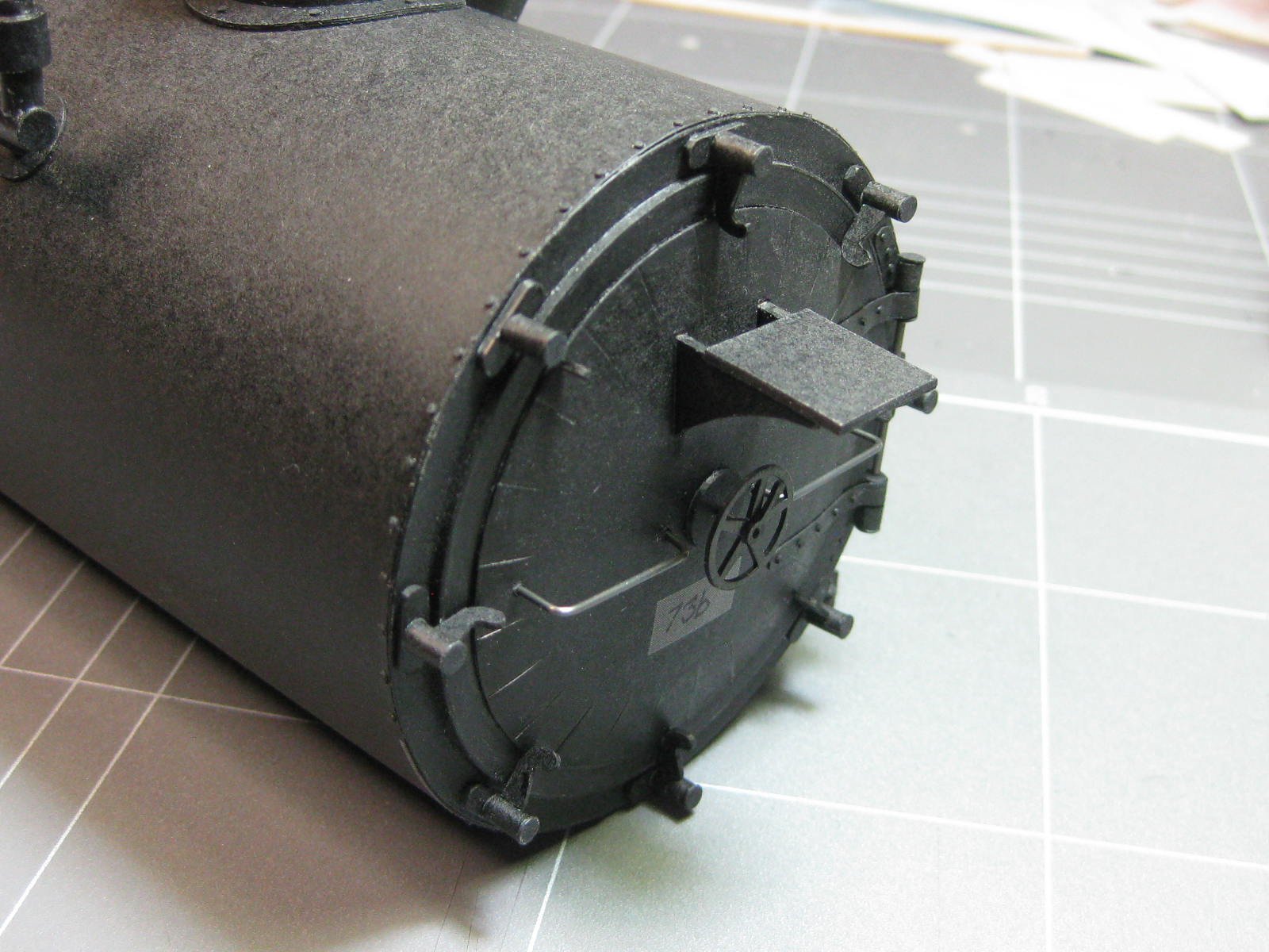
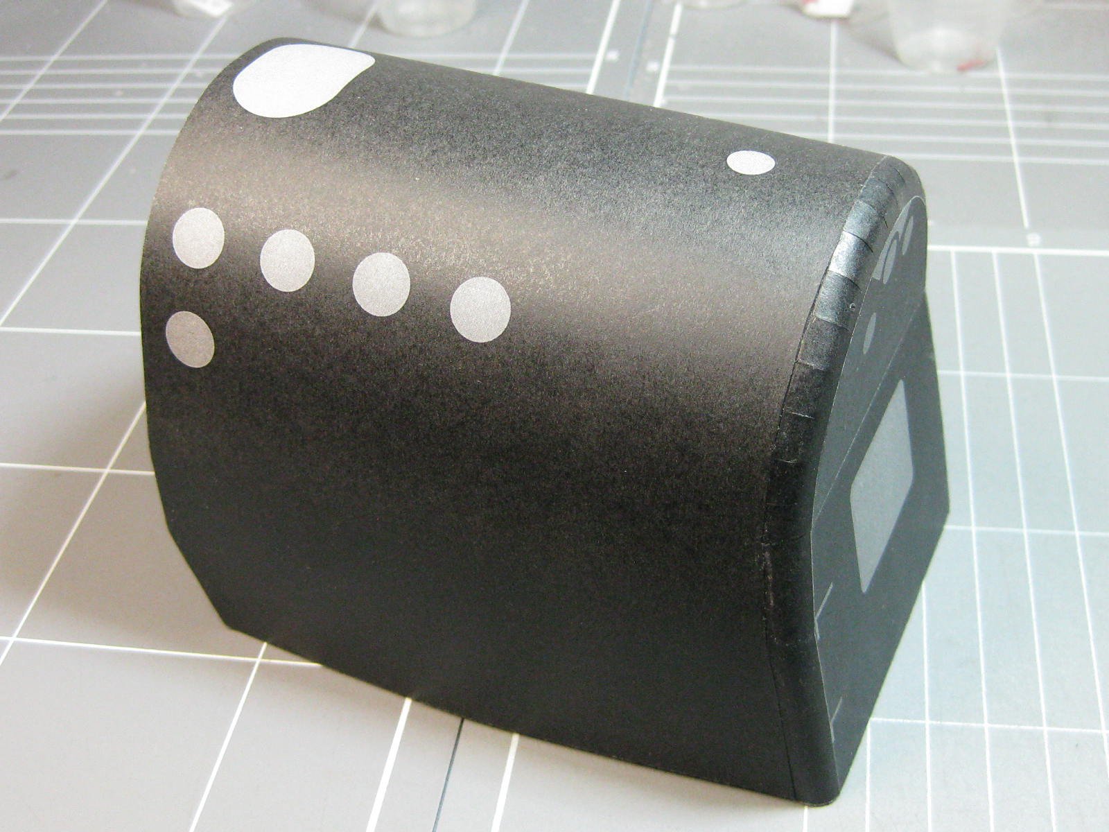
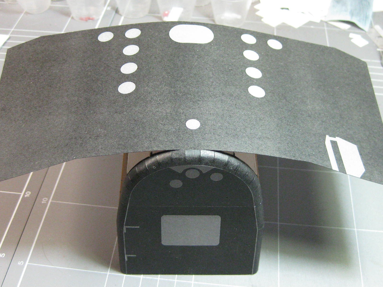
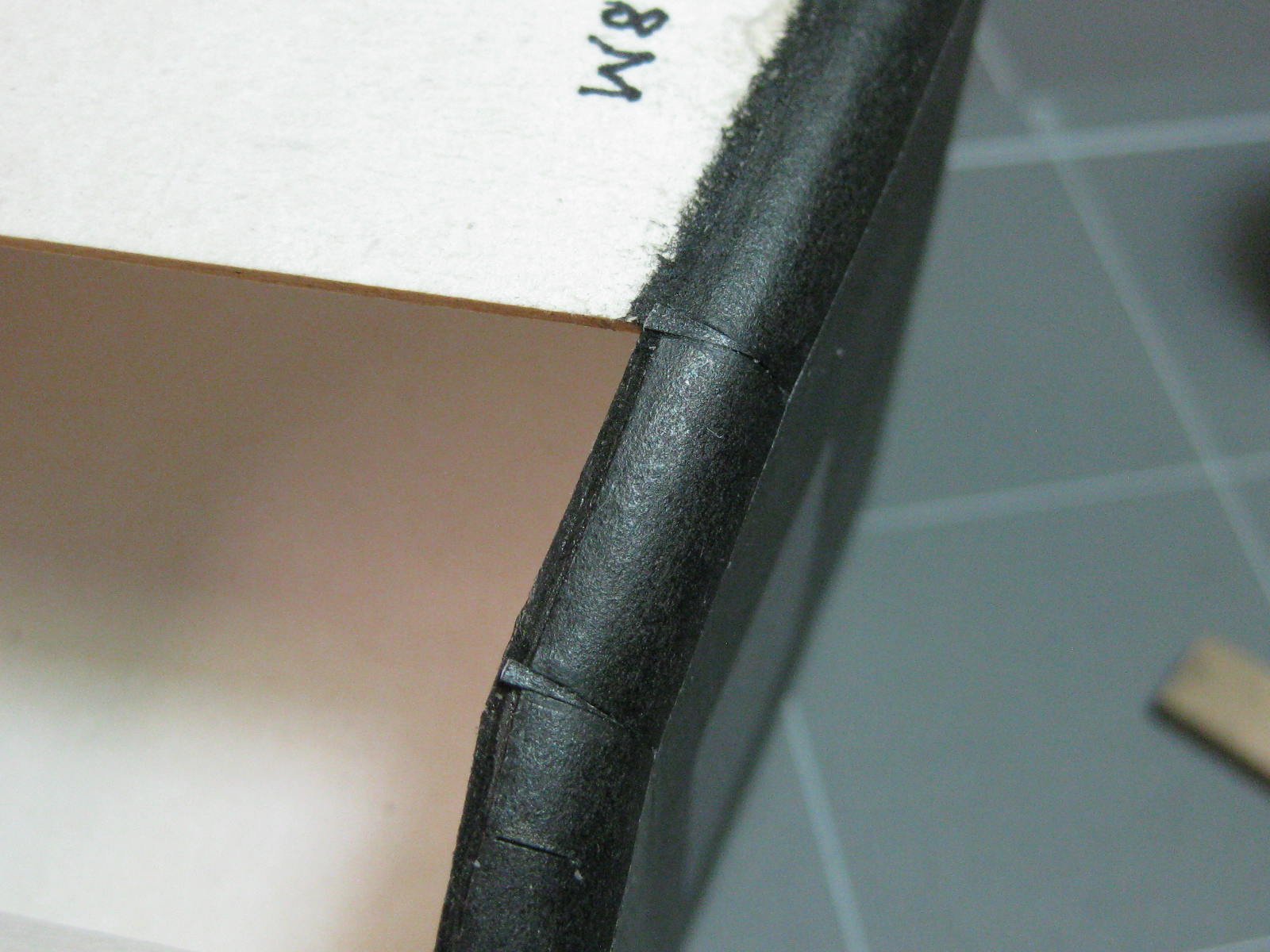
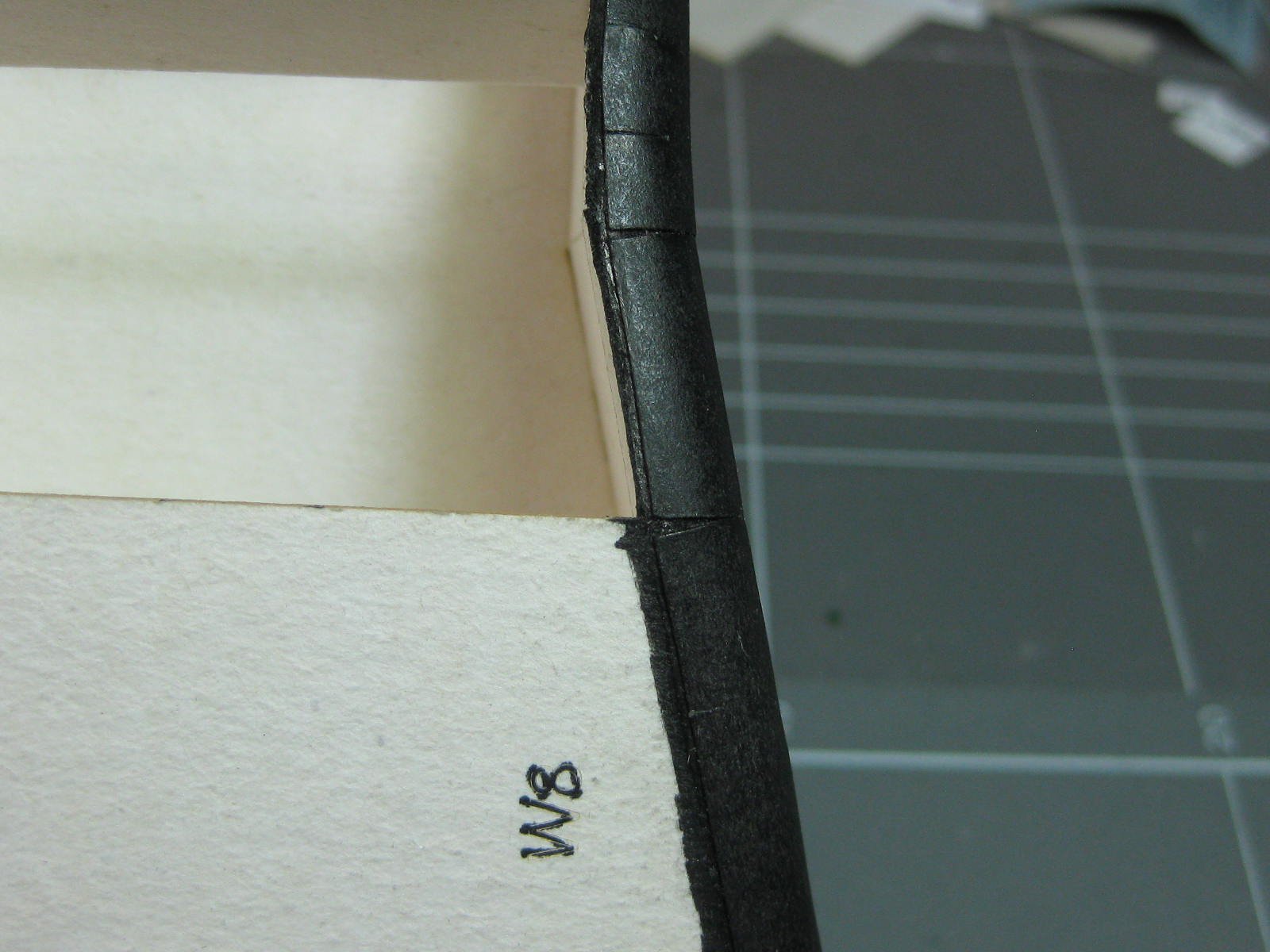
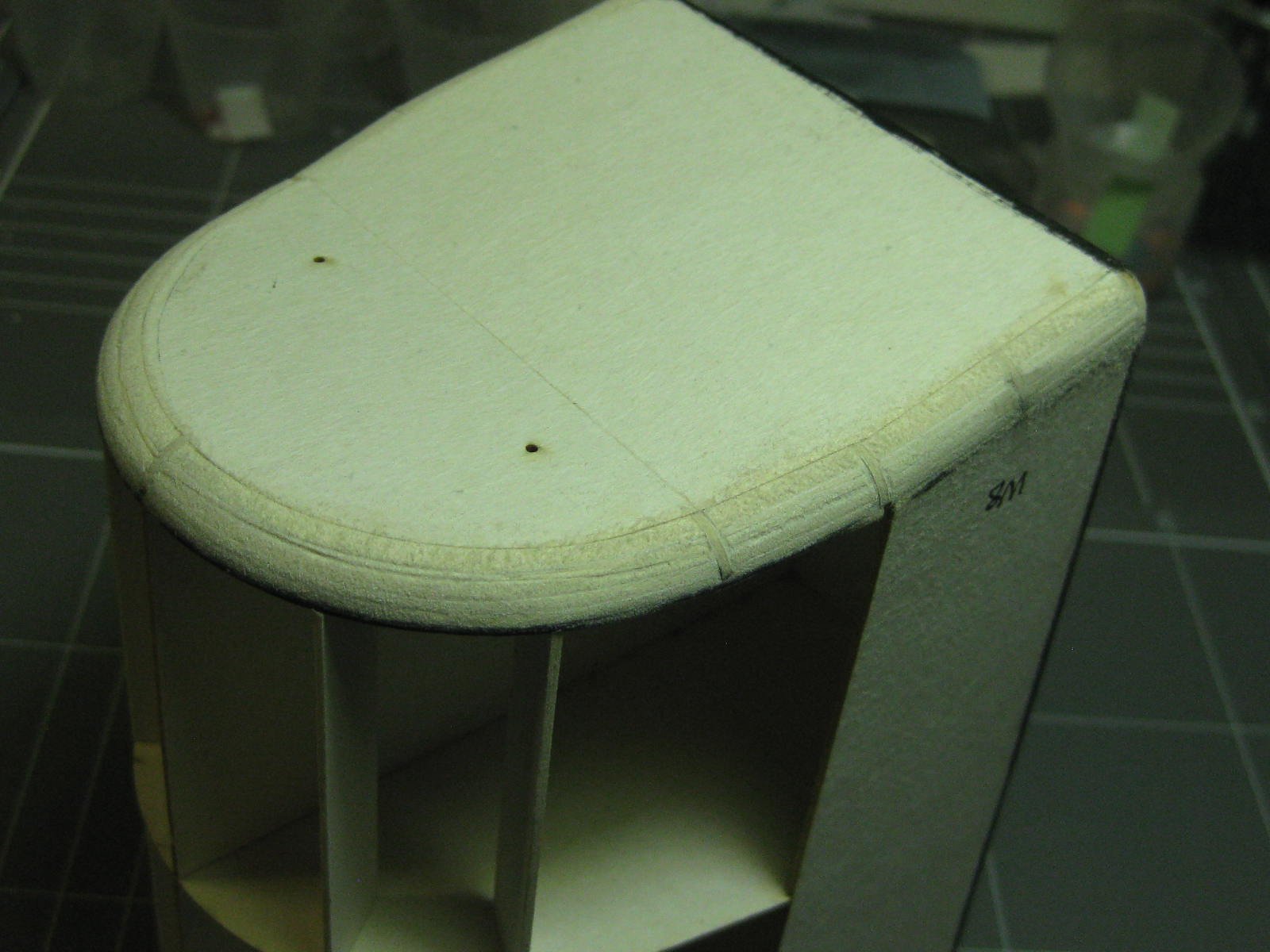
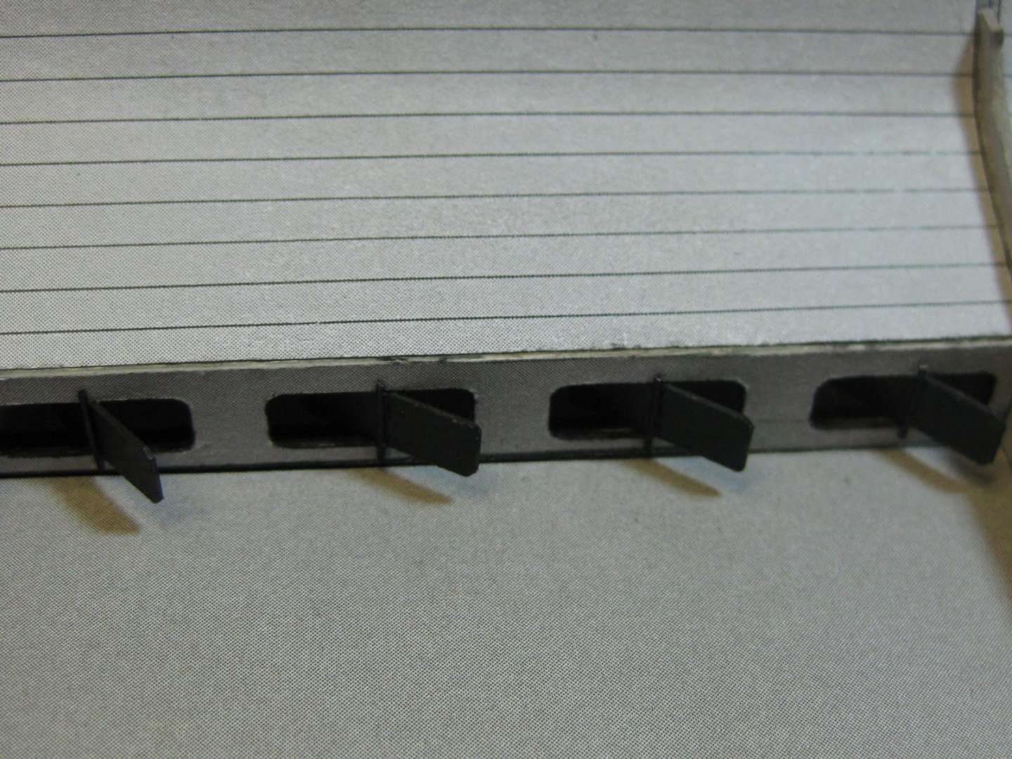
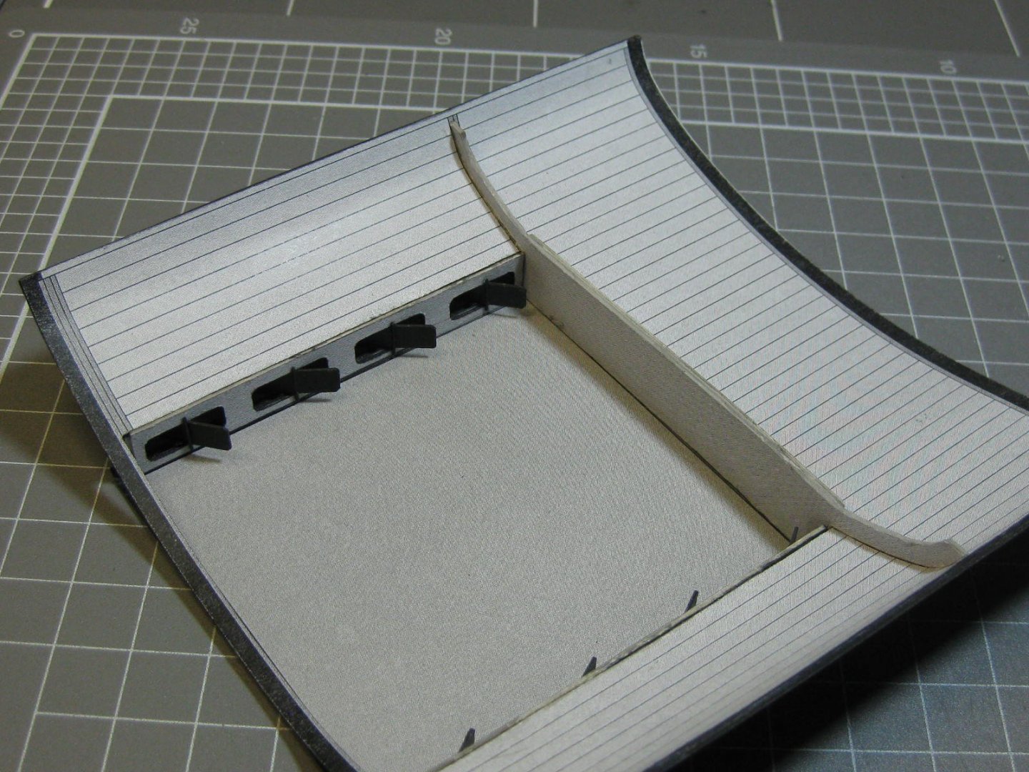
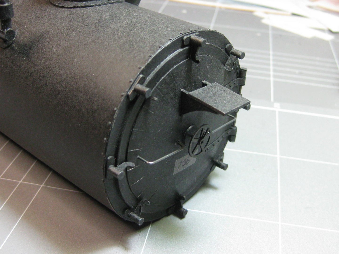
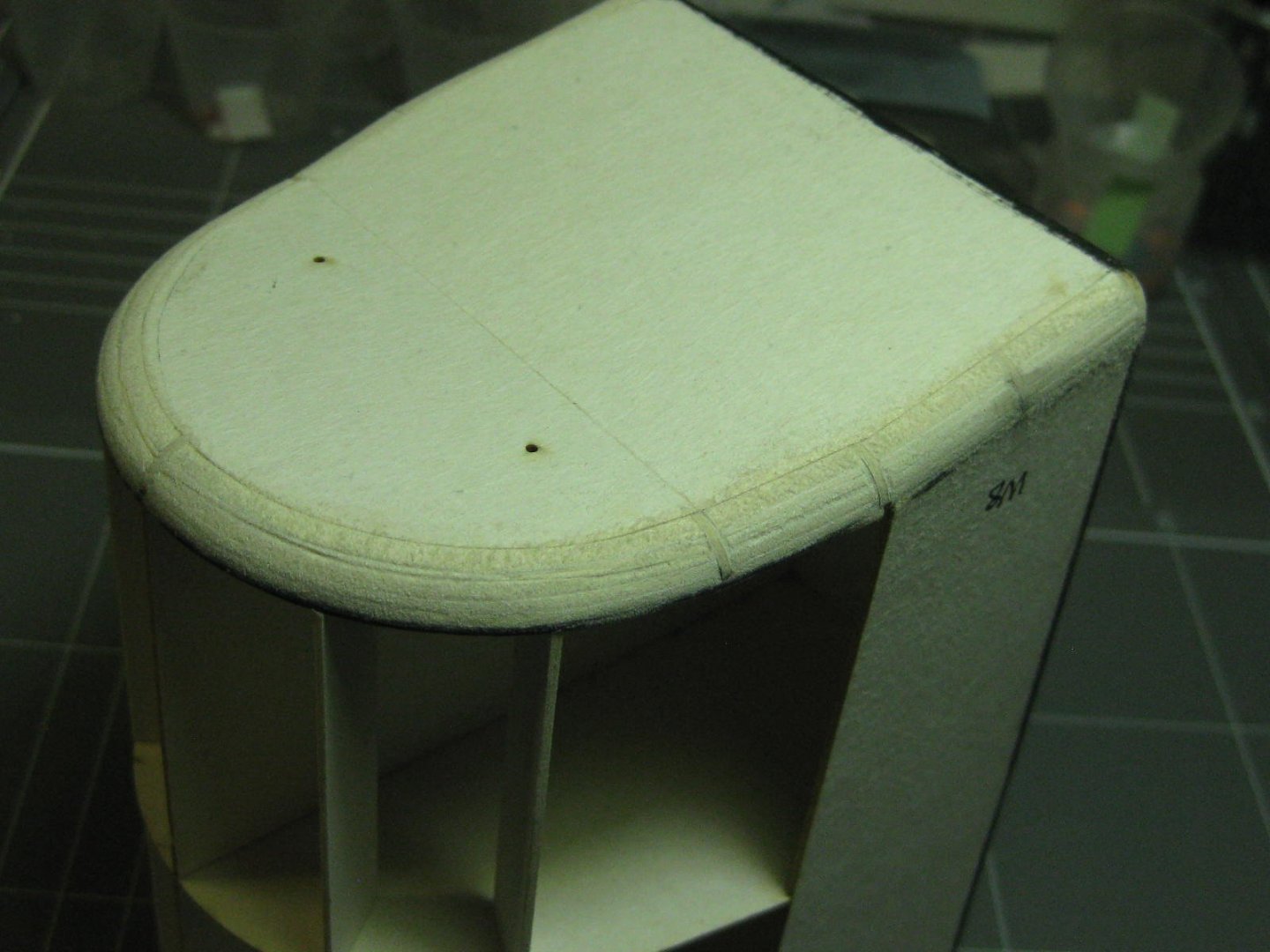
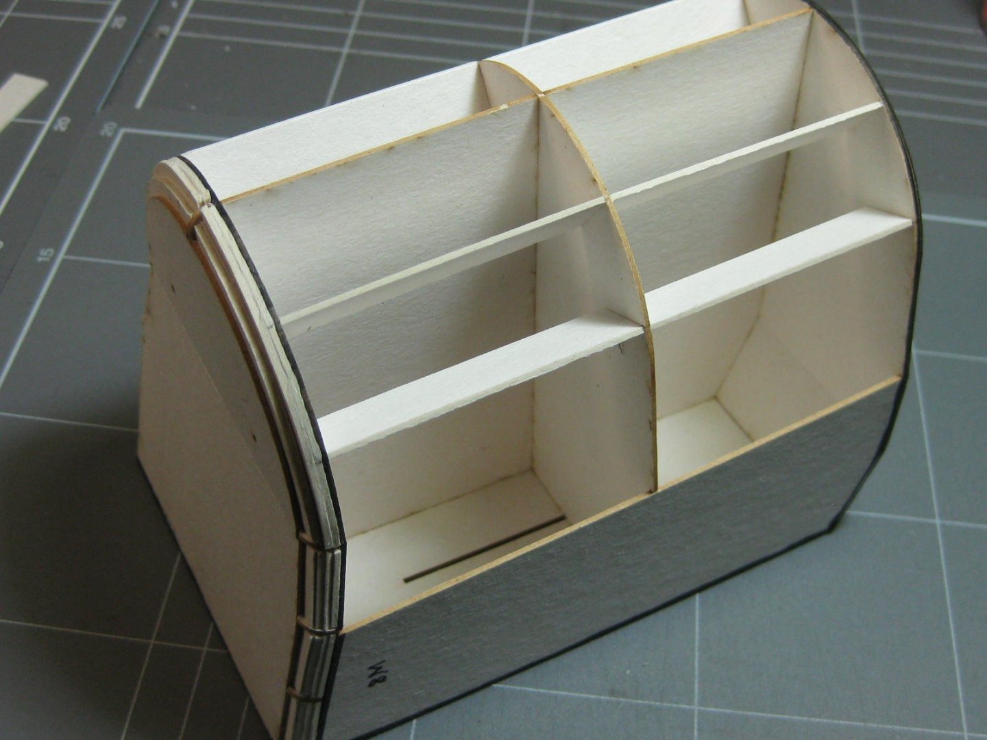
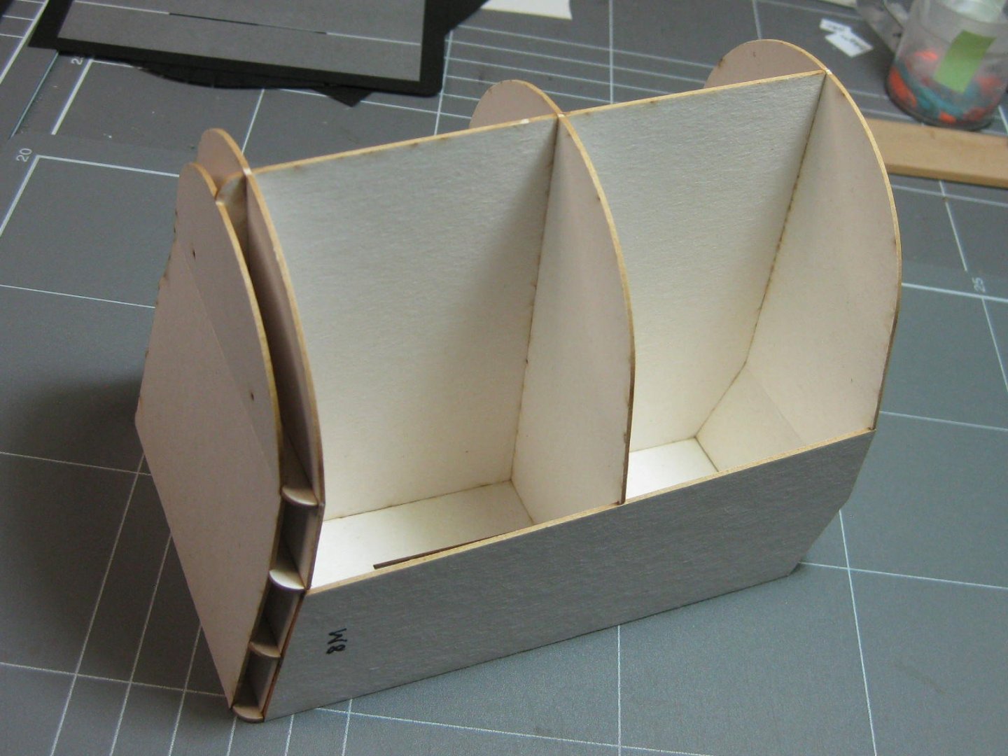
Hopefully I can remember how to take one on my old camera - it's been about 10 years since I last did . The firebox. There were laser-cut support frames for this and the boilers. I added some extra 10mm wide strips that just touch inside the sides to prevent any crushing, and also to stabilise the whole unit : The cabin end has a rolled edge. I filled in the rounded part to give me something to work to : Filling in that edge really helped a lot to make a nice even roll without any "wobbles". The lighting makes it look a bit uneven in the pics - in reality it's turned out close to perfect . I glued each tab one at a time to give me time to push it into place properly : The slots between four of the tabs wasn't drawn correctly, and I finished up with gaps in them when I glued it up. I filled the gaps with some scrap paper. They are nearly impossible to pick with the naked eye : The skin was a beautiful fit, no adjustment necessary : The ash box was a rather fiddly thing to glue up, but I'm more than happy with the result : I glued some tapered card around the inside of the edges to stop any bowing while gluing the ash box to the fire box : The result was pretty good : Danny


- 150 replies
-
- 19
-
-
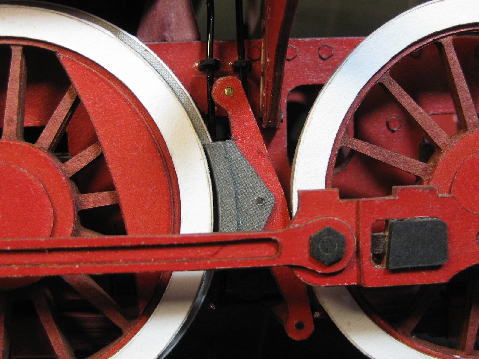
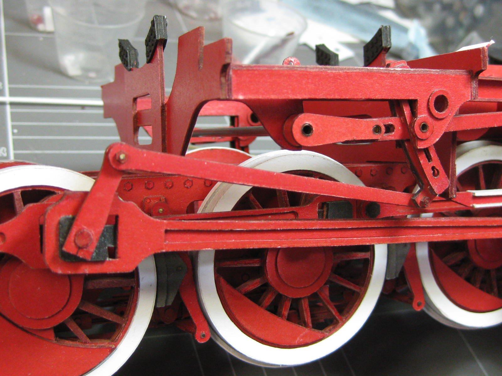
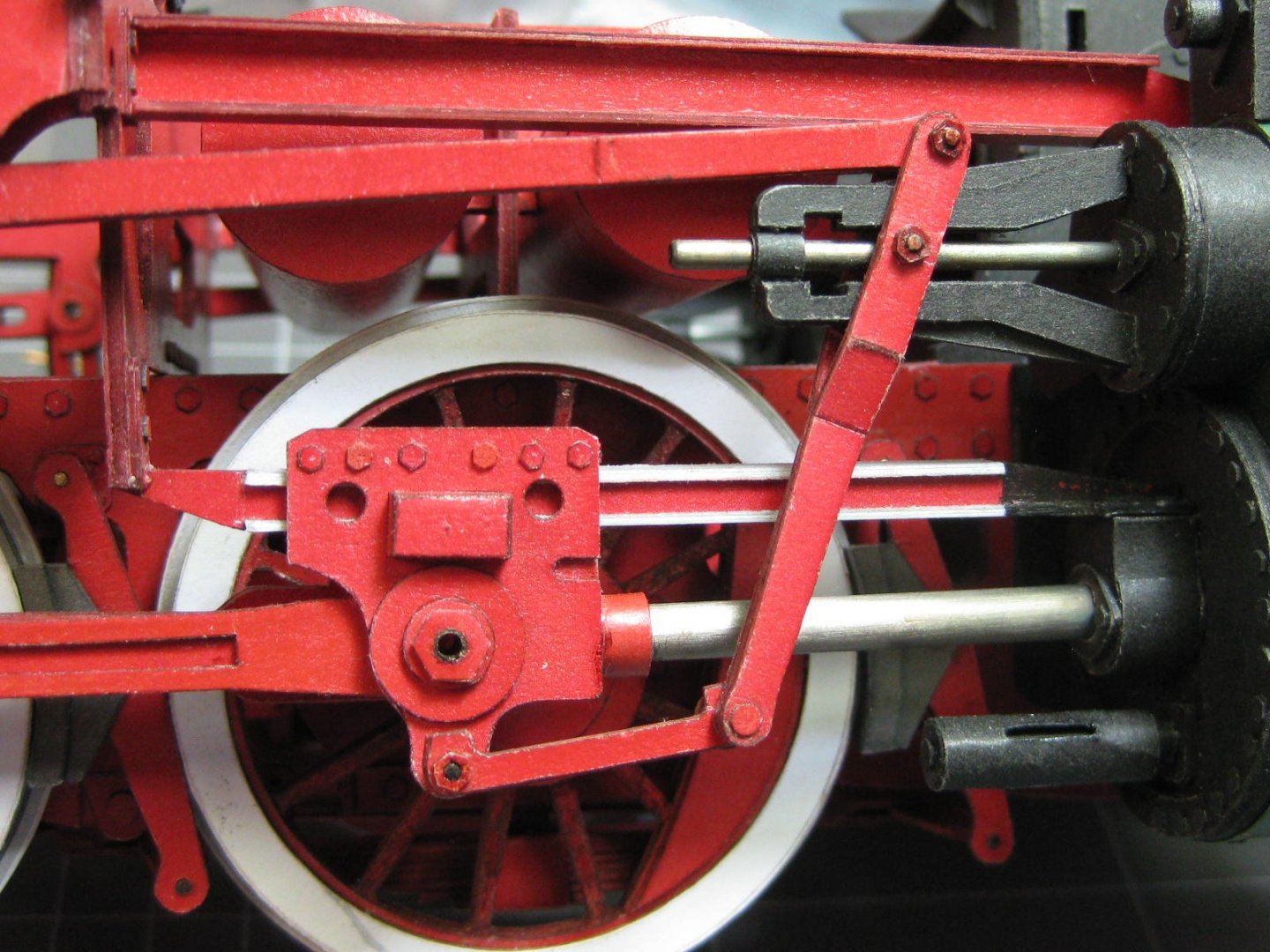
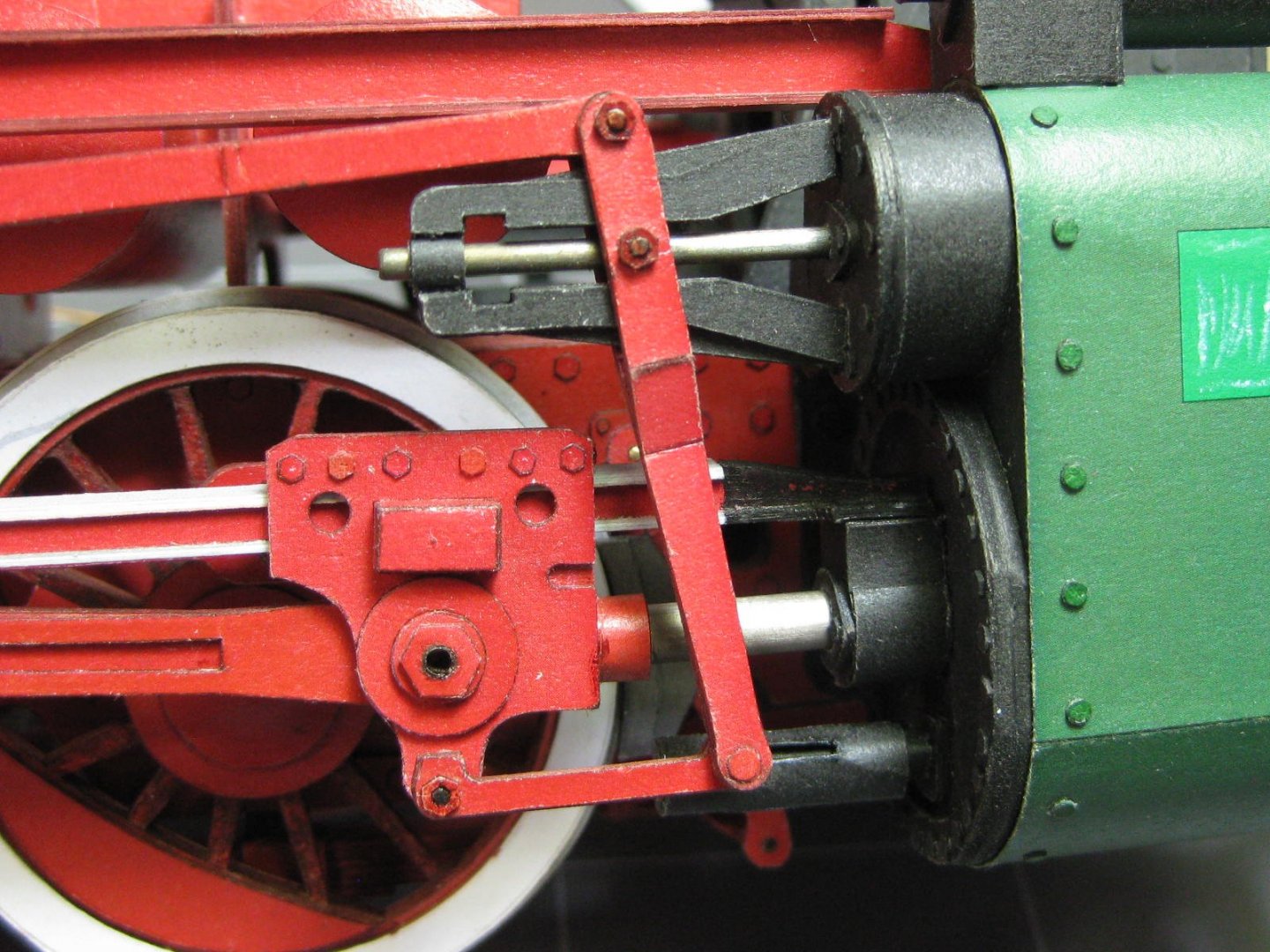
Getting the crank mechanisms to actually work took some thought, as the kit makes no provision for this - it's simply all glued together. I made every joint moveable (too many actually - the valve control mechanism is separate from the drive cranks and didn't really need doing) by punching and pinning every one. Most joints are held together with paper "nuts" which are the only parts of the joints that are glued. Here is the slide for the upper shaft which also needs to pivot : Some close-ups of all the right-hand side crank mechanisms : With everything now in place the crank movement has really improved. It will get close to perfect once the drive wheels actually touch down - at the moment they are in mid-air as they don't have a flange like the other wheels. I've started making the boilers. More progress updates will follow as I have something to show. Cheers, Danny


- 150 replies
-
- 20
-
-
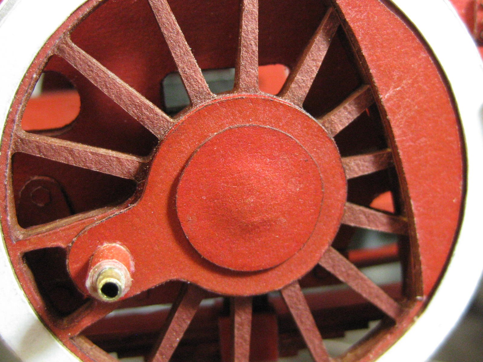
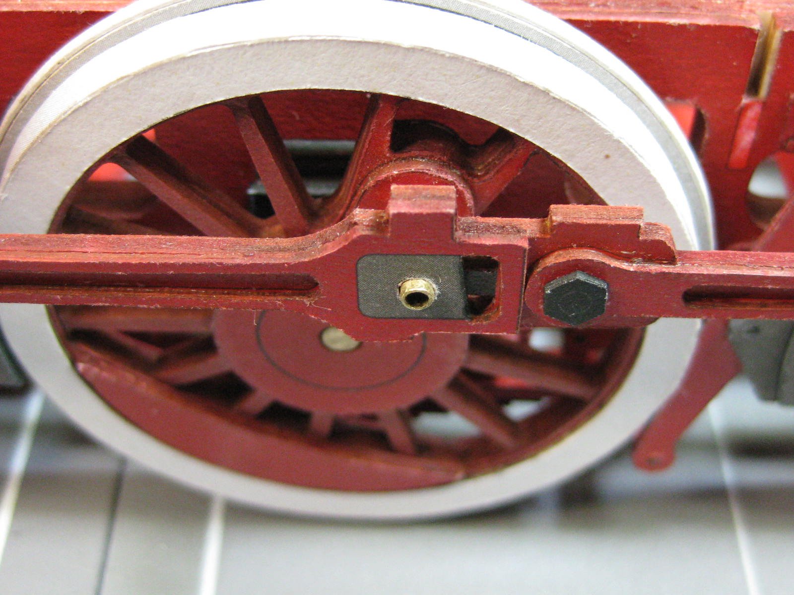
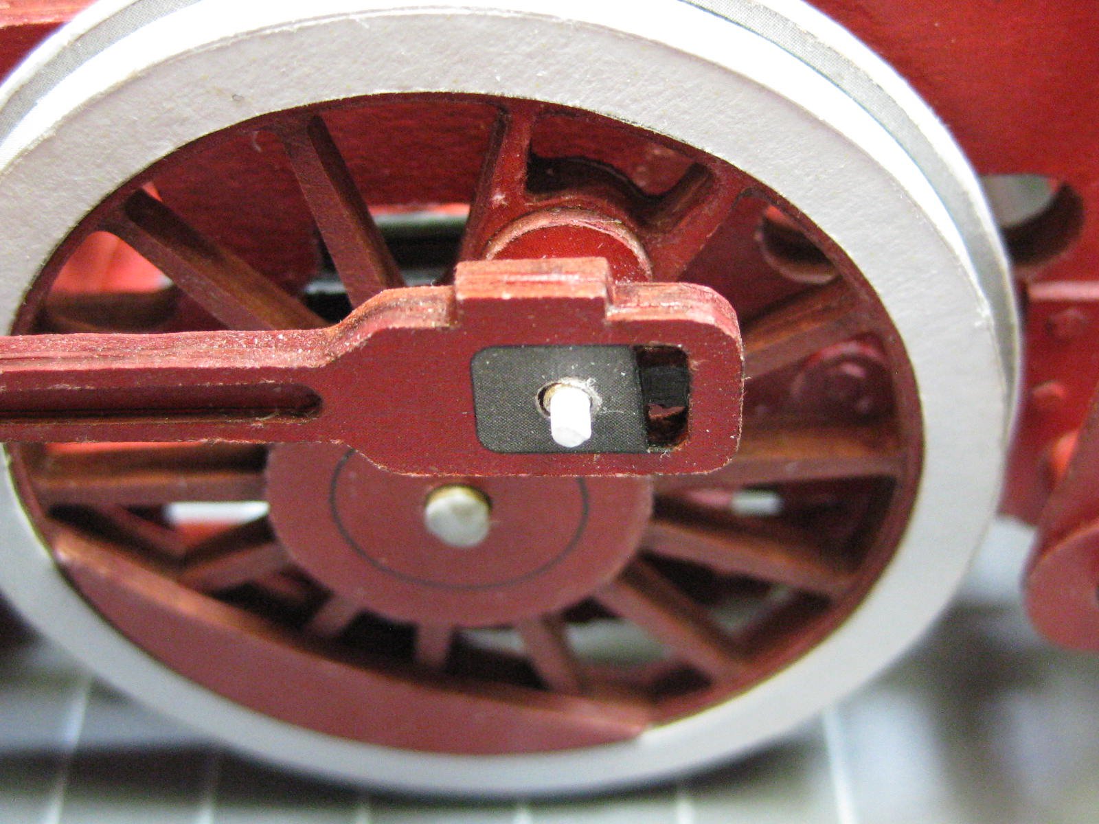
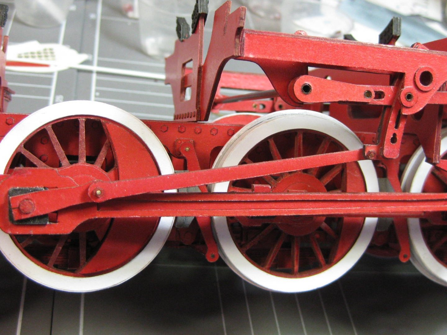
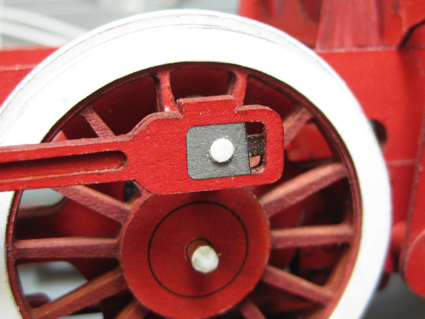
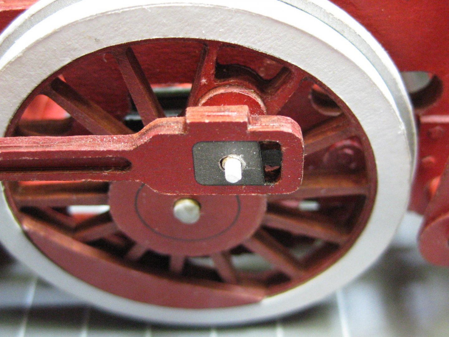
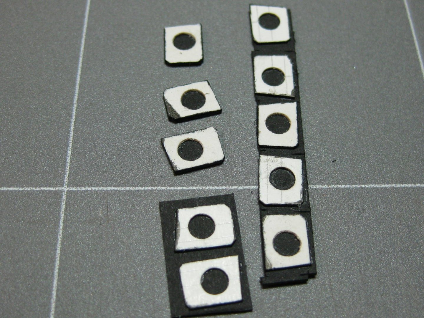
Welcome to my build Gary. Paper modelling has it's own challenges, the solutions to some of which I've been fortunate to pick up from other MSW members and others from European Paper modellers. The medium is huge over there, probably as big as wood or plastic modelling . In the words of Bachmann Turner Overdrive - "You ain't seen nuthin' yet" . The crank pins are dealt with in similar fashion to the axles, using 2.0mm brass tubing and 1.6mm styrene rod which I heated with a small soldering iron to mushroom the end. It was then cleaned up and filed as flat as possible with a diamond-coated needle file : Once the axles were all installed I made some "hubcaps" from scrap paper. In my opinion they look better than the bare axle, which is actually the "correct" way on the original : The crank pins are also covered, I punched out some 0.5mm paper and glued them to the back of the printed parts to give them enough clearance : Danny


- 150 replies
-
- 14
-
-
Good luck with that model Caroline, it looks a reasonably "easy" one to try as a first loco (if any are actually easy ). I think you'll find the Modelik kit to be quite a good one, detailing is nice and the instruction diagrams are understandable. It seems you've avoided a kit with a couple of thousand rivets, instead you have a couple of hundred louvres to cut . Take a look through THESE PICS of a finished model of one. They may come in useful for your build. P.S. A laser-cut Rail set is also available, makes a nice "stand" for the loco. Cheers, Danny