


Alan Cabrera
-
Posts
10 -
Joined
-
Last visited
Content Type
Profiles
Forums
Gallery
Events
Posts posted by Alan Cabrera
-
-
-
On 1/16/2023 at 11:48 PM, Blas de Lezo said:
Thank you Amalio for your explanation. So, if I understood right, the only goal of the internal mold is just provide stiffness to the ribs while working. That makes completely sense, but I find nevertheless double work, first cutting and sanding the molding external part with high accuracy and later again, cutting and sanding the same curves for the ribs' part that is in contact with the mold.
In any case, the result is astonishing.
I was thinking the same thing as well. However, when you figure in the work it takes to lay down the inner planking with its steelers and drop planks, it makes sense since planking on the inside of a hull is not as easy as planking on the outside. With this mold technique, you’re always planking from the outside. As for the amount of work involved, I imagine it’s no more work than the first planking of a plank on bulwark ship. As a matter fact, looking at the mold, it kind of looks like a plank on bulwark set up.
I’m aspiring to build Le Fleuron and I’m not quite sure that this technique would lend itself well to the ship’s complex web of lateral reinforcements. But, for these Spanish ships, it makes perfect sense to me.
-
On 9/15/2016 at 3:33 PM, dvm27 said:
His frames are constructed above, below and around the faux-port lids. They are used as templates to help frame the hull. The real question is how will the plug be extracted from the framed hull later on (as seen in the early photos)? The mysterious Amalio will reveal all (hopefully) in his own time.
I have just started reading this blog, so this can possibly have been discussed in later pages. What I’m wondering is how are the internal surfaces of the axial timbers faired before being layered on top of the internal planking that wraps the mold.
- Keith Black and mtaylor
-
 2
2
-
Bitao, I love your brass fittings. What kind of brass stock do you use and where do you get it from?
Also, I'd love to see a tour of your workspace!
- billocrates, mtaylor and Keith Black
-
3
-
14 hours ago, Bitao said:
I'm sorry to disappoint you.
Oh, not disappointed at all! I love to see different Craftsmans’ interpretations and decisions. Those stanchions are also quite lovely.
If I did have to mention a disappointment, I would say that I would very much LOVE to see a video of you crafting them; I realize the difficulties inherent in creating such a recording and don’t want make you feel awkward. It’s just that you are sooooo good at crafting those lovely tiny bits…
-
On 6/11/2022 at 1:44 AM, French Mr Bean said:
When I look at the photos, a question comes to me: "Where is the dust?" 🤣
Bitao, a master chef of ship building, adheres to the work clean ethic of clean tools and clean workspace. 🤣
-
On 6/8/2022 at 9:35 AM, Bitao said:
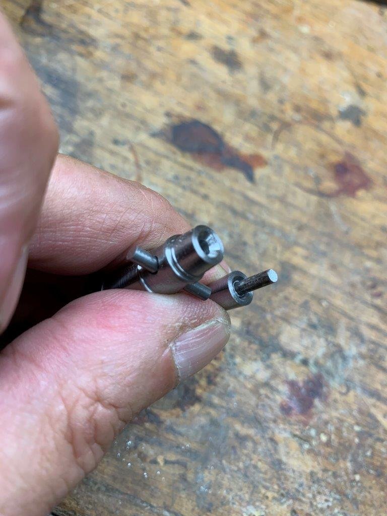
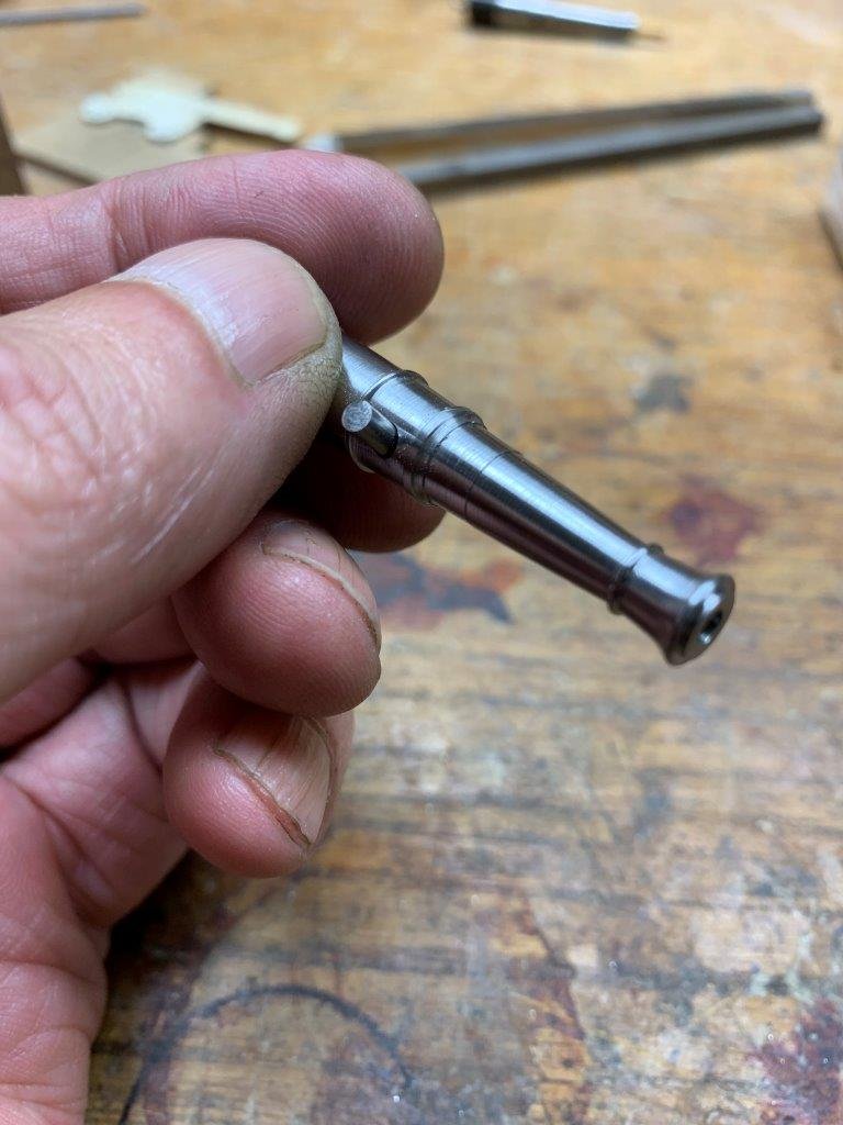
I have been faithful to the original design, but the following picture of the drive rod support in the complete set of books and drawings do not see the detailed description. I've been going over the EdT process again and again, and I still can't find the exact answer except for the following photo, which seems to me to be different from the drawing, as if it's a column instead of an“L” in the process picture.
I interpret the cross-section drawing as cutting along the axis of the drive rod. This is why one sees a solid column where the L-shaped stanchion is, at the end of the drive rod.
Figure 33-33 of the book matches your interpretation, exactly. The paragraph that details Figure 33-33 talks about how one could construct the L-shaped stanchion in the same manner that copper wire was used to create the iron knees, or cut them from copper plate. To me, this confirms that the stanchions that cap the end of the drive rod are L-shaped.
As L-shaped stanchions go, yours are quite lovely. Looking at your photo, I noticed that they are a shiny copper and I assume that you intend to blacken them as I think that they would have been made of iron; blackening them makes them consistent with Edward Tosti's model. Also, I see that there are no crank handles offset from the drive shaft. I guess the plan is to add them once you feel comfortable with the L-shaped stanchions?


WDButler carvings
in Build Logs for the Carving Group Project
Posted
This kind of information is gold. Thank you so much for taking the time to make these posts!