


Frodo
-
Posts
53 -
Joined
-
Last visited
Content Type
Profiles
Forums
Gallery
Events
Posts posted by Frodo
-
-
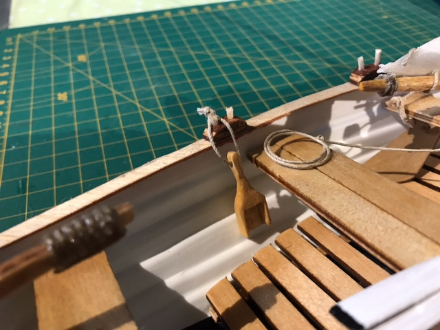
Today I had to create some more details just because it is fun

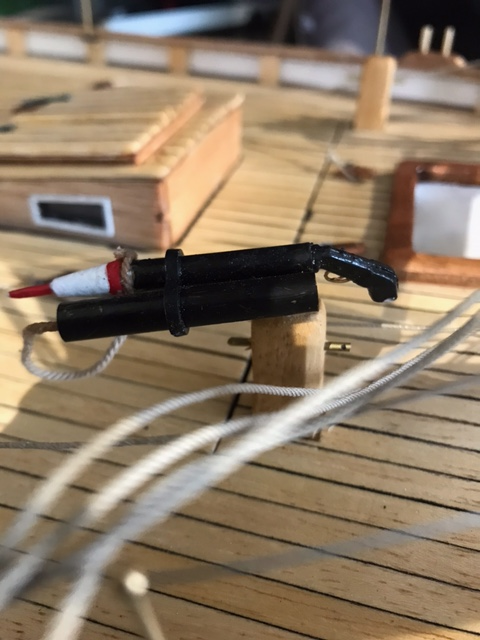
6 old fashion fenders made from "jutetråd" (from corchorus-speci-plant), a rope made from hemp/hamp ("hampfenders" could be the English word?)
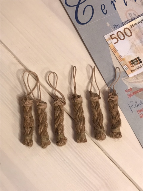
A tiny anchor (old fashion grappling hook style), as I remember them from my childhood in small rowboats.
And a fishing harp, measures about 17mm x 17mm.
- Prowler901 and GrandpaPhil
-
 2
2
-
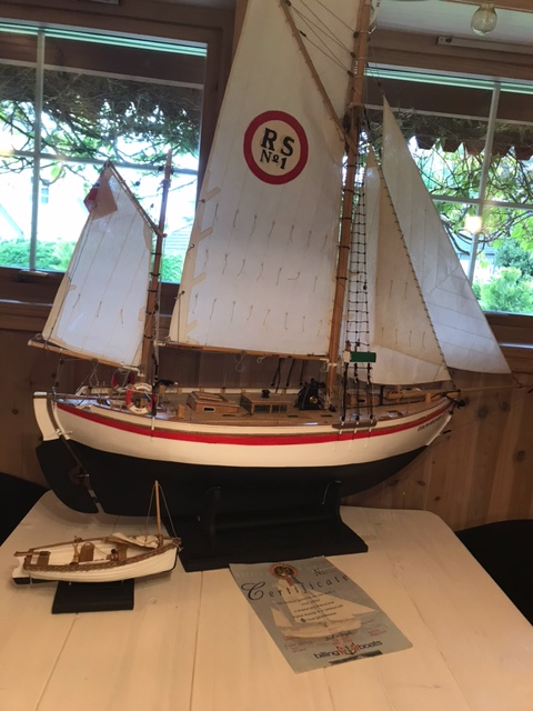
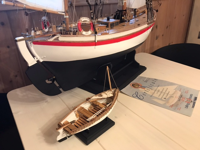
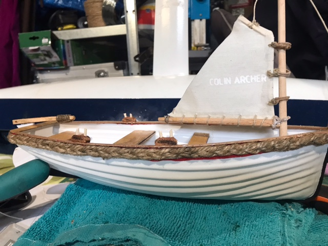
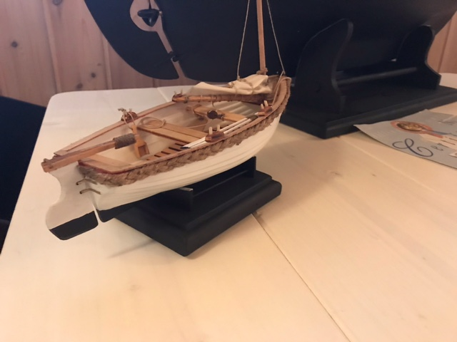
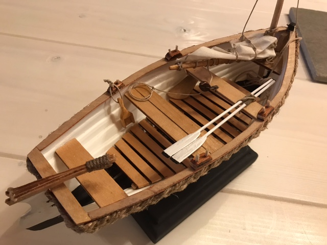
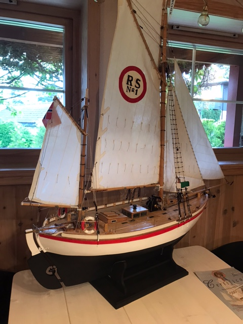
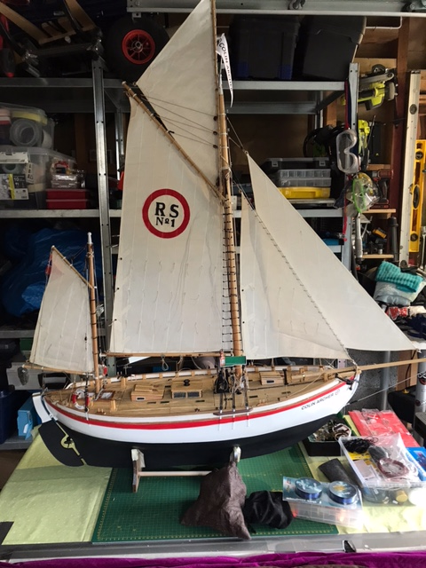
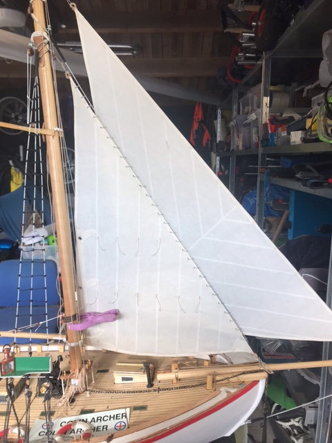
Another update. I guess I'll have to say that both the models now are done "exteriorwise". Still need to do the RC-work and the interior of the Colin Archer, the Sarik "jolle" (dinghy) I consider to be complete.
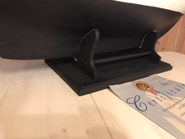
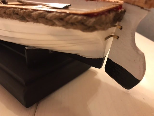
The stands for the boats are painted with same color as the anti-fouling. I do however have a concern that the CA now weights close to 9 kg and it puts a lot of pressure on the hull while in stand, worst case it could "pop" the deck. Guess I will remove the leadballast to avoid damage while in the stand.
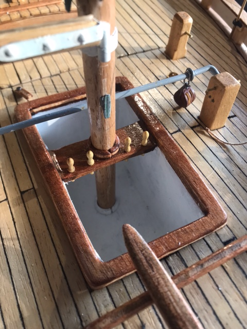
Rig-top:
The baseplate for the stand measures 38cm x 26 cm:
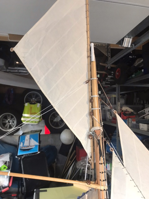
The sail is just hoisted for photosession
") It will be lowered and packed while being pulled behind the mothership or on static display.
It will be lowered and packed while being pulled behind the mothership or on static display.

Thanks for watching
- GrandpaPhil and Prowler901
-
1
-
 1
1
-
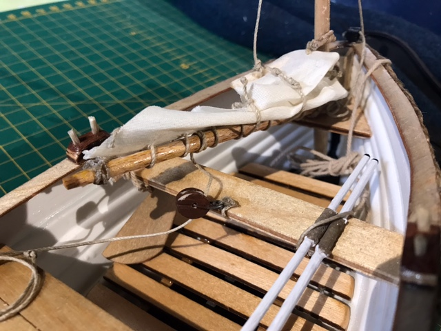
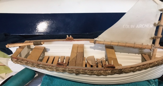
Short update, currently trying to create the Sarik "jolle" (dinghy):
- Paul Le Wol, ct mike and GrandpaPhil
-
3
-
1 hour ago, Nick Alderson said:
Hi everyone,
I too have just joined this forum to see how the rest of you have got on with the Colin Archer. I am building my third one in 9 years so I have forgotten some aspects of this build. The instructions really are poor but I suppose it makes it a bit more of a challenge. Lots of "one step forward, two steps back". The kit I bought had been in store for years, ABS hull version and lots of the laser cut pars held in place with sellotape.
I think the trick is to be patient and work carefully. One thing I can't find is the height of the supports for the railings. Any ideas ?
NickHi, and welcome. Indeed there is some "forward and backward" combined with trial and errors
If you are referring to the wooden support I found this hidden in the manual (nbr 16 into 18mm pieces):
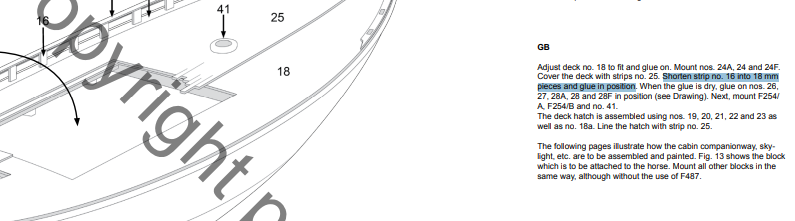
Here is also a link to the instructions I found it in (2xpdf):
-
Reconsidering servo setup below deck. I could use a total of three servos incl mainsail if I want to/need to have separate controll of "jib" (flyer) and "stay sail" (inner foresail), however not necessarily... inspired by the "sailtails" youtube video:
... but then I'll most likely will have to remove the cabin/saloon...
-
The hole for the rudder linkage will be sealed for sure, hopefully I dont forget to do it...
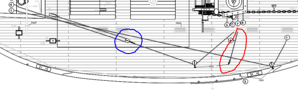
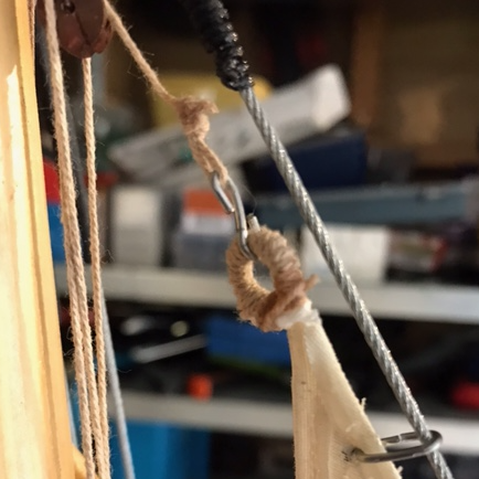
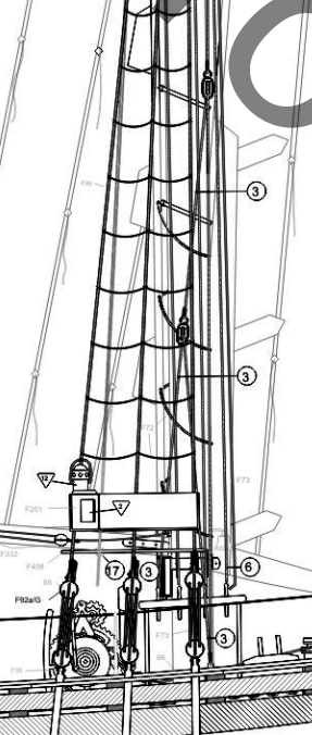
About the distance that the inner foresail and the klyver will move:
- Rope nbr 4/inner foresail: has a block originally on deck (blue circle), and I've kept it, so it gives a 50% reduction as you mention.
- The part of rope nbr 4 (in red circle) has been removed. The rope comes back from the a medium block attached to the clew of the inner foresail.
-
However, this is theory... sailing in practice might give another truth
-
Posting some lessons identified so far, might prevent others from doing the same.
The two following photos below shows the original setup for genoa sheets, it will for sure not work properly.
However, if I skip the "dead-eye" on deck and take the sheet straight from the genoa via the deckblock, then I get approx. the same traveldistance on the servo as with the "klyversail". And I will get rid of the two blocks attached to the cleat on the sail... that could work... in theory. I will give it a try.
Another issue: The "loops" I made for sail sheets gets tangled up in other lines when I tackle. Therefore I need to find another solution. I am considering removing the "loops" on genoa and "klyversail", maybe made from eyelets.
I also need to make the "harpoon" removable as it gets will get tangled up in the mainsheet.
-
11 hours ago, Geam said:
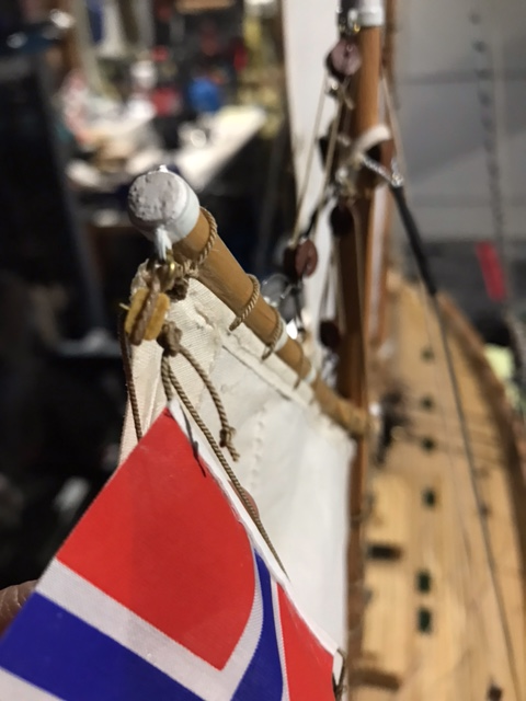
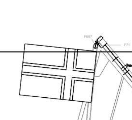
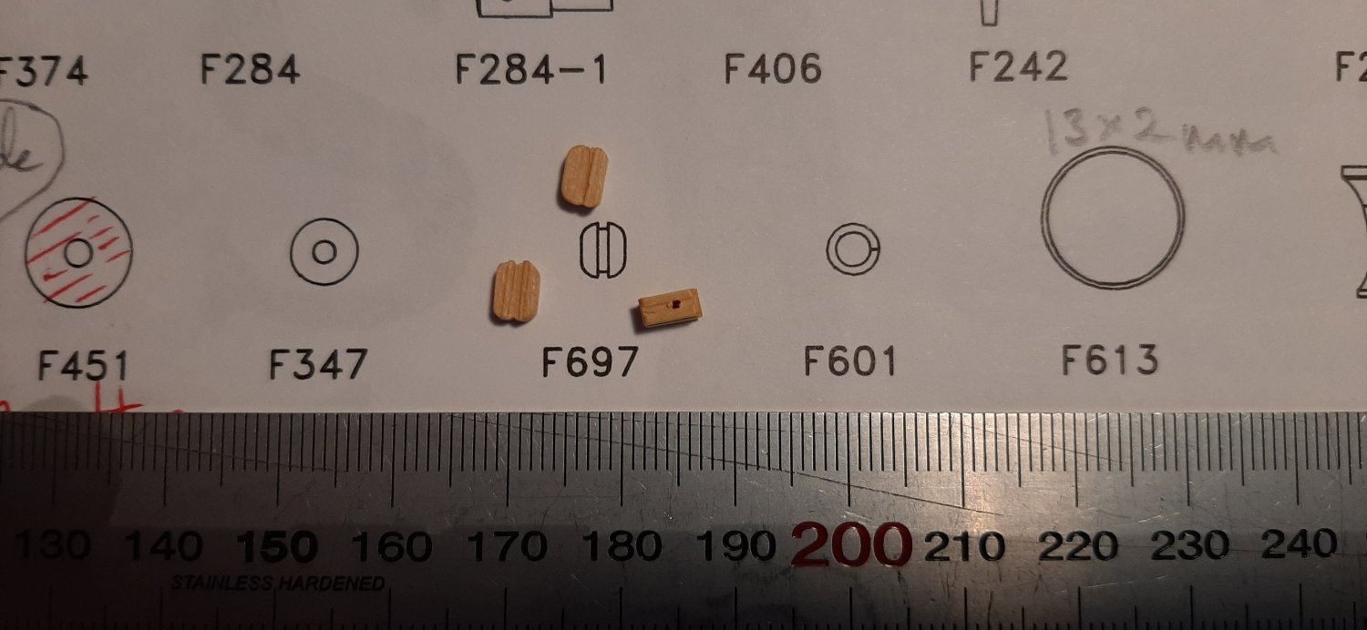
Thanks for finding F697. It's clearly marked on the drawings for the top half of the sailplan, but I did not see it! Not sure yet if F697 for the top of the flagline or part of the mizzen rigging.
Part F92M is a 'rudder horn' -to attatch the rudder servo to the rudder. It is nicely marked so you can bend it to 90*
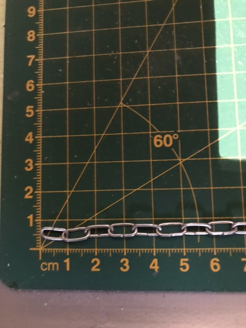
I will consider chainlinks to strengthen some of the parts. Where did the chain come from? Clas Ohlson?...etc. Made something like that on the Fisher34 but can't remember where the chain came from!
About F697 I saw it in the photo on the box for the kit.
The chainlinks I cant remember, think I bought them 5 years ago for a similar project. But I'm a big Clas Ohlson user
F92M as rudderhorn is not needed then I guess, I mounted another one I had laying around. But thanks for clarification.
-
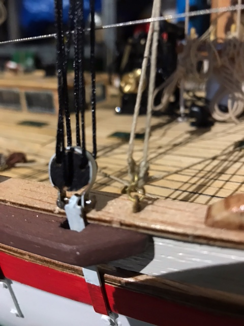
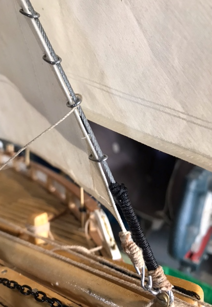
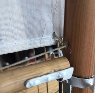
So about the earlier mentioned "dead eye" and rope nbr 3. Here is what I ended up with, however I am not sure if its 100% correct.
The rope from the upper most block in the picture is attached to the fall for the "klyversail". The other end of the rope tied to the pinrail on left side of mast.
-
This is the chainlinks that I use for various purposes. By turning one end 180degrees you get a "hook" shape.
-
F697 above the flag.

-
I still have the part F92/M, not sure where it suppose to go. Any ideas?
-
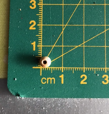
2 hours ago, Geam said:
Hi, the photo you posted of a round bead with a hole in it is part F347 -I think. There should be 11 of these. I forgot to post a photo of the what I think is part F697 which is a tiny dead-eye... (jomfru? in Norwegian?) I have 3 of these, but maybe they are not F697?
As regards R/C control, I am only going to control the foresail (Klyver) with a sailwinch. My inner foresail will be left to self-tack on a thin elastic sheet tethered to a small 'horse' just forward of the main mast. To control the inner foresail properly would need a dedicated servo I think. It would be complicated -and maybe even impossible- to set up these two sails from the same servo.
My sheets to control the klyver run in guide tubes up through the side decks abeam the main mast. I will take a photo and post it on my RS1 log. These sheets will then be run through blocks on the capping rail. Not sure if I will use the kit blocks but will probably try these first. Replace them with brass blocks if they break.
I have noted your changes with regard to making the RS1 more suitable for R/C sailing. Look like very good ideas to me👍
George

Now I understand, yes it is the nbr F697.. I only had one of those small woodpieces (F697). It goes at the rear end of the mizzenfork to hoist the flag in. I will try to make a photo later.
-
Status as of now;
I will continue to work on the RC-setup. I dont think the original genoasheets will work together with the "klyver seil" (the one most to the right). I'll try to post some photos on the issue a little bit later, but I think the mainissue is that the two sails dont have the same "leverage" (gear-exchange), and I was planning to put both sails on one servo... tbc...
-
3 hours ago, Geam said:
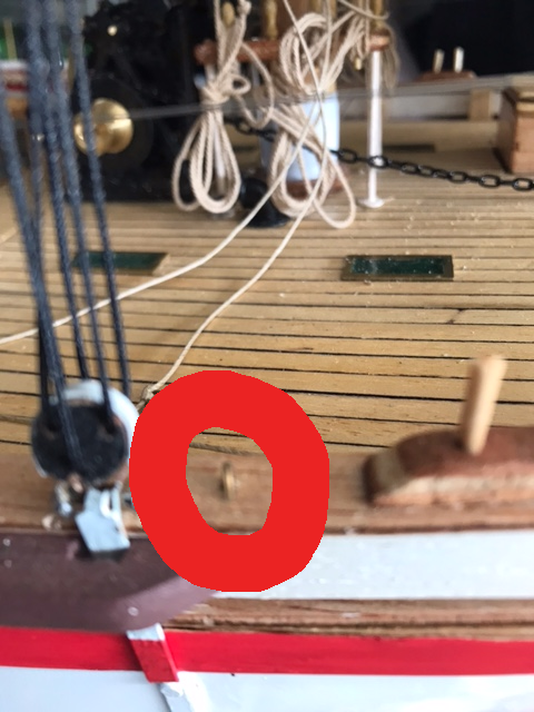
Otherwise, I'm not sure the blocks and securing 'eye-pins' F92/I, are strong enough to handle such a large sailing yacht. I suspect that originally the RS1 kit was designed as a static model.
Some of the 'eye-pins' might be exchanged for screwed-in eyebolts on my RS1.....and maybe the blocks for the foresail sheets will be brown-painted metal.😬
I also suspect the RS1 to be a static, so I have also done some adjustments:
Used 1,5mm steelwire as forestay (1mm should be enough, but couldnt find it in store).
Used 10mm steel chainlinks on the genoa ("forre stengestagseil" in norwegian).
Made "loops" at some of the sailcorners.
Mizzen
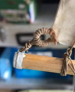
All sailedges are folded and glued with 1mm cordline in center, then sewn. Makes the edges stiff and durable I believe.
-
4 hours ago, Geam said:
Hi again Frodo, not the same topic at all but... do you -or anyone else- know what part nr F697 is for? The parts list states that there is ONE of these in the kit. My kit has THREE. The same part is listed for the '728' -all wood RS1 and here too there is only listed ONE in the kit.
It is obviously a static block or dead-eye, has a tiny hole through it from the side. I have not found this part marked on the drawings....yet. It's probably there, but where!
Otherwise, I'm not sure the blocks and securing 'eye-pins' F92/I, are strong enough to handle such a large sailing yacht. I suspect that originally the RS1 kit was designed as a static model.
Some of the 'eye-pins' might be exchanged for screwed-in eyebolts on my RS1.....and maybe the blocks for the foresail sheets will be brown-painted metal.😬 Anyway I can't use modern metal blocks and tackle as on my Fisher34 model so it will all have to be well epoxied in place and hope for the best. Not planning to sail in stormy weather anyway.🤢
George
I only have one of the F697, and I dont see it on the building instructions either
However, it could very well be used at the "root" of the boom/mast.
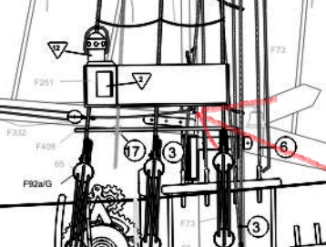
I didnt install it thou... but F697 could be attached to the "metal eye" I guess.
-
4 hours ago, Geam said:
Hei Frodo.
On the Sarik site--if you write 'dinghy' in the 'search' window at the top of the page. you will see the list of dighys. When I searched just now it was the third down on the list. The have a 13" and a 9" plastic clinker hull. £11.00. I bought the 9" as reckon this is the nearest to a correct size for the RS1.
You need to mark and cut the sides of the hull to get a shape to resemble a 'Nordlandsjolle'. The line of the bow is not quite the right shape, but when all the other detail is added it looks good enough I think. I can post some of my construction photos here on your build log but first you have to say if you actually want them on your log! You may have already seen them here -or on the Model Boats forum? Not sure if I posted the actual build photos on modelshipworld.
George
Thank you, I found it on the Sarik website now. Ordered a 9'' right away
I saw your pictures in another thread, and think I will build something similar of the Sarik "jolle".
-
3 hours ago, Geam said:
Had a look at the drawings. The eye-screw you refer to is for the nr 3 halyard (uphaul) for the foresail (klyver). You need to study both the plan view and the side view drawings. The halyard goes from the pin rail (naglebenk) up to a block and back down to the eye-screw on the capping rail. The same eyescrew is used to anchor the next block up in the sytem too! This system apparently gives a 8X leverage to tighten the forlik of the Klyver sail. If you follow the nr 3 sheet you will see a few more blocks in the system before you get to the top of the klyver sail! The Klyver sail does not have a forestay but on the RS1 has a wire sewn in to the forlik of the klyver.
Thank you. I re-checked with the plans, and can now see its nbr 3. Indeed a lot of blocks and halyards
-
4 hours ago, Geam said:
Yes dinghy is indeed too small. Have suppose that you seen my semi-scale effort? '
George
Yes, I have seen your Sarik "jolle". Looks nice. But I couldn't find it on the Sarik site. Do you know if the "jolle" has a modelname?
-
-
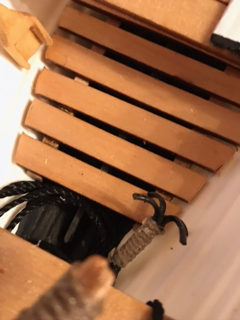
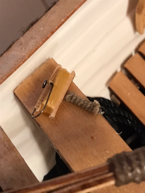
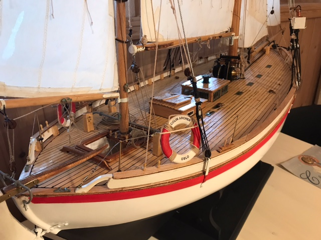
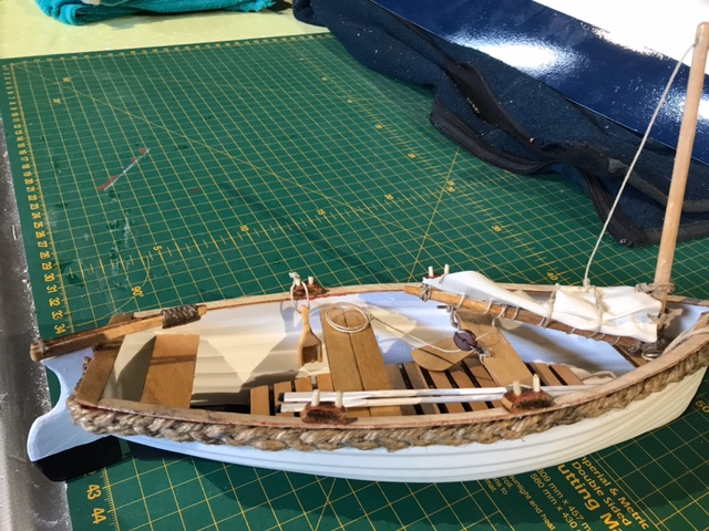
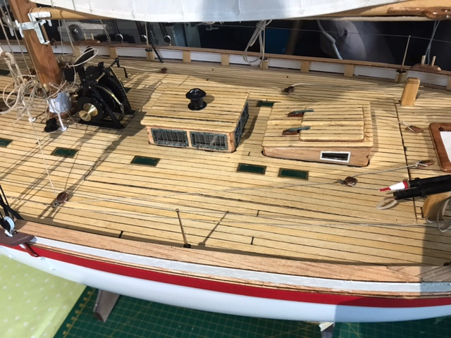
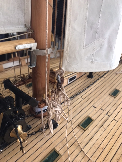
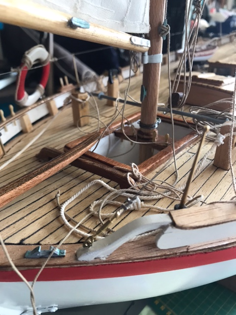
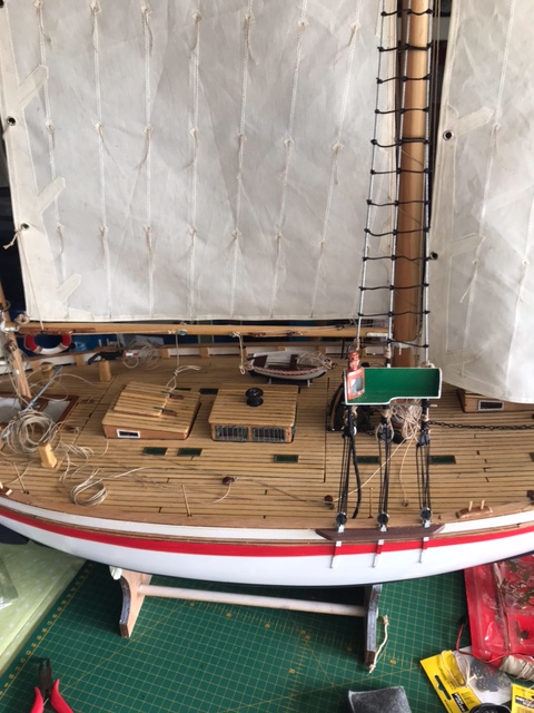
Hi, just an update on the CA-project with some random pics.
Currently there are ropes and lines "all-around" as I'm figuring out how to do the RC-servo set-up.
I've used ropes/lines from Billing Boats, Syren and Amati.
I'll post some more pictures when things are less messy on deck in a few days.
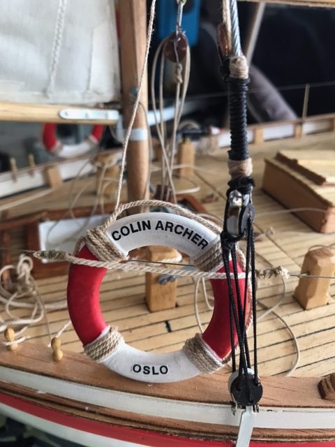
"Attaching" the lifebuoy I used a rope which was sewn onto the wire, I know the original is somewhat more robust, however I like the clean look.
I'm not sure if the sheet for the genoa will work with RC-setup depicted below, I might have to simplify it.
Hoops and loops in place on main mast, very time-consuming and demanding for fingers and eyes....
I guess the deck will require 2-3 more layers of lacquer.
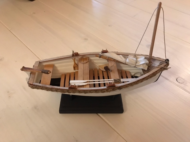
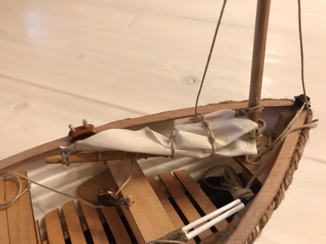
Made a little dinghy, but it became way to small (10 cm ish) for a 1:15 size, need to get a bigger one
-
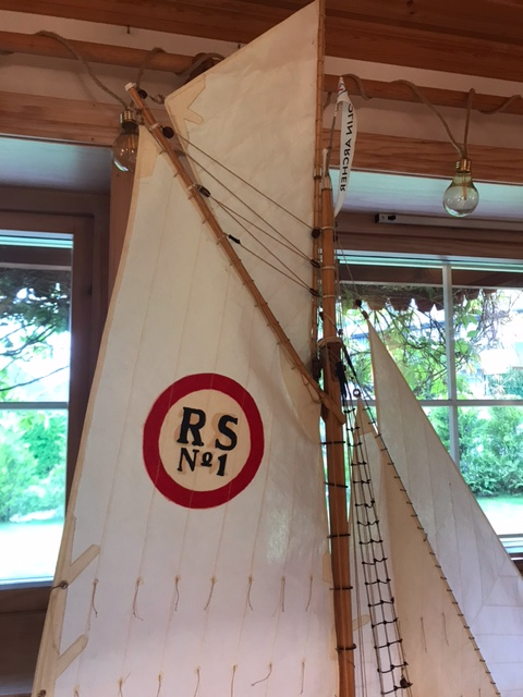
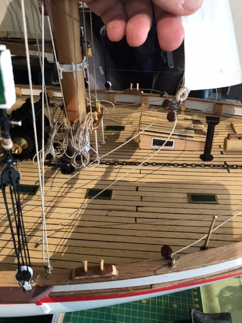
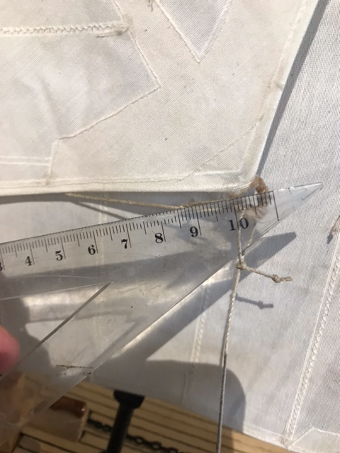
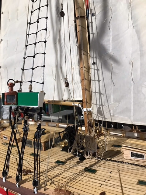
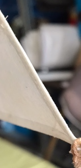
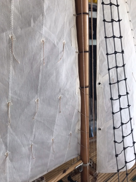
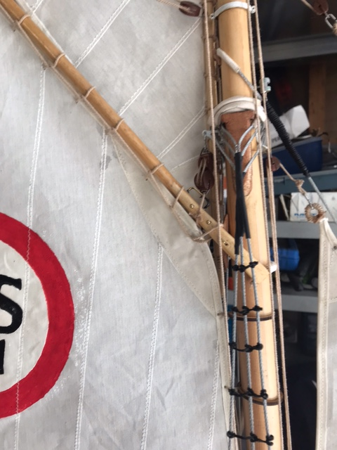
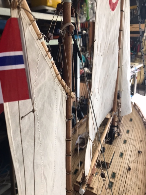
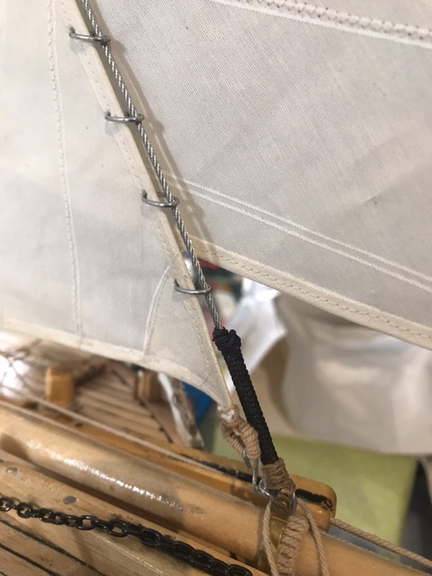
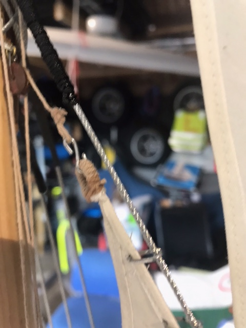
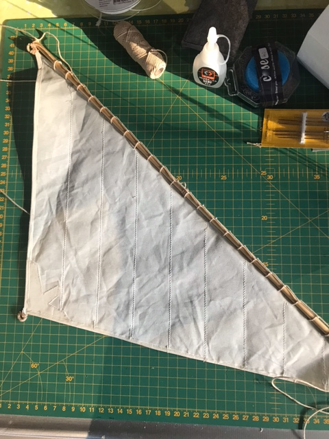
An update on the sails, which now are more or less complete for mounting. It takes time "building" the sails, but it is great fun. I could not find any details on how to attach the sails to the rig so I improvised from my own experience. My solution might give others an idea of how they would have done it, so Im just posting some close up pictures.
The two genoas:
I decided to attach the rear genoa with 10mm chainlinks, as I find the small rings provided with the kit rather weak. 10mm chainlink has an opening of 8mm, the wire is 1,5mm and the chanlinks are approx 5mm from leading edge of sail, this give a small airgap of approx 1,5mm between the sailedge and the forestay. It is 20mm between each chainlink.
Mainsail sewn with "reefropes":
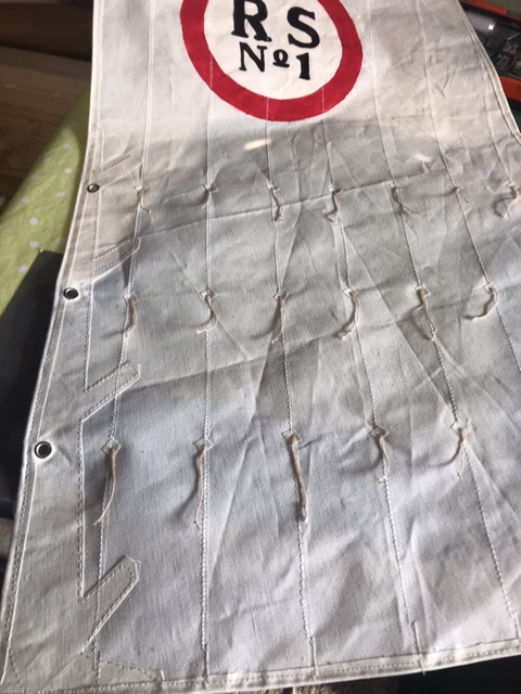
I used 4mm eyelets as reefeyes. I believe the reefeyes should be placed on the trailing edge made from rope, however this solution is close enough
I'm considering to sew the edges of the eyelets with white thread.
Topsail is "sewn" onto the topmast. About 20mm between each "ropeloop". The cordline in the fold is important for a strong edge to sew in:
-
4 hours ago, Geam said:
Received a reply e-mail from Billing Boats. The new owners of Billing do not know anything about the '414' kit they say. So they do not know why there are two nr 54. One of them deffinately should go on top of the mast support nr 35 as shown on the plan. So the other one can be stuck anywhere it might look right!🤪
George
Thank you George 👍
I ended up putting the 2 x nbr 54 as depicted. One above 35, and one at the floor of the cockpit:
-
Lately I've been working on the sails. It sure takes a lot of time as my sewingmachine skills are a little rusty.
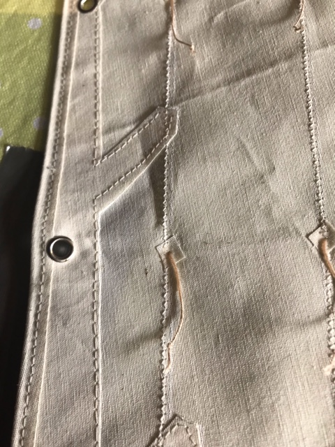
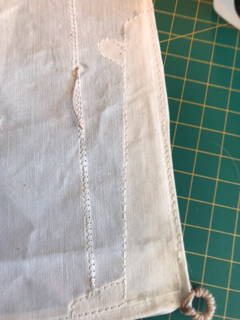
The mizzensail is complete. As mentioned in earlier posts I first folded and glued the edges with a 1mm white cordline as core. This provided a stiff and neat form to the sails. Then all the edges and patches are sewn. In the corners I have made "loops" to have as tack/clew points. I will not need a loop in each corner of the sails, but the can easily be cut of.
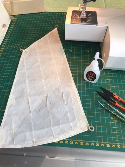
The "cornerloops" are made of the excessive 1mm cordline which then were twinned in 1mm "brownish" thread...
Nordlandsbaaden by Ekis - FINISHED - Billing Boats - 1:20
in - Kit build logs for subjects built from 1751 - 1800
Posted
Lovely build @Ekis. I do have a coupe of questions as I am about to build the same model:
1) Which technique do you use to nail/clink it?
2) Do you know if the rudder is cut of compared to the original.
Again a great build model, thanks for sharing.