MORE HANDBOOKS ARE ON THEIR WAY! We will let you know when they get here.
×


CTDavies
-
Posts
73 -
Joined
-
Last visited
Content Type
Profiles
Forums
Gallery
Events
Everything posted by CTDavies
-
 Forget Brexit, custom dues and taxes. I live in the EU and I‘m getting one of these even if it kills me. As John Adams of Aeroclub fame once told me: if a modeller wants it, he‘ll find a way to get it. 😆
 -
Hello Starlight, I started this model about five weeks ago. This is where I am now. I‘ll be happy to tune in every now and then. chris
- 82 replies
-
- 1
-

-
- Fly
- Victory Models
- (and 2 more)
-
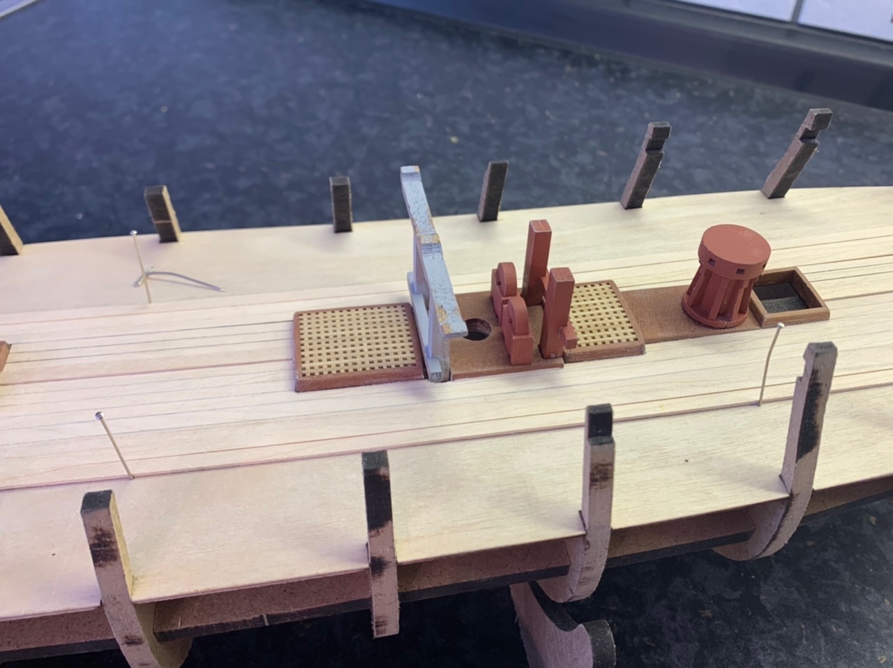
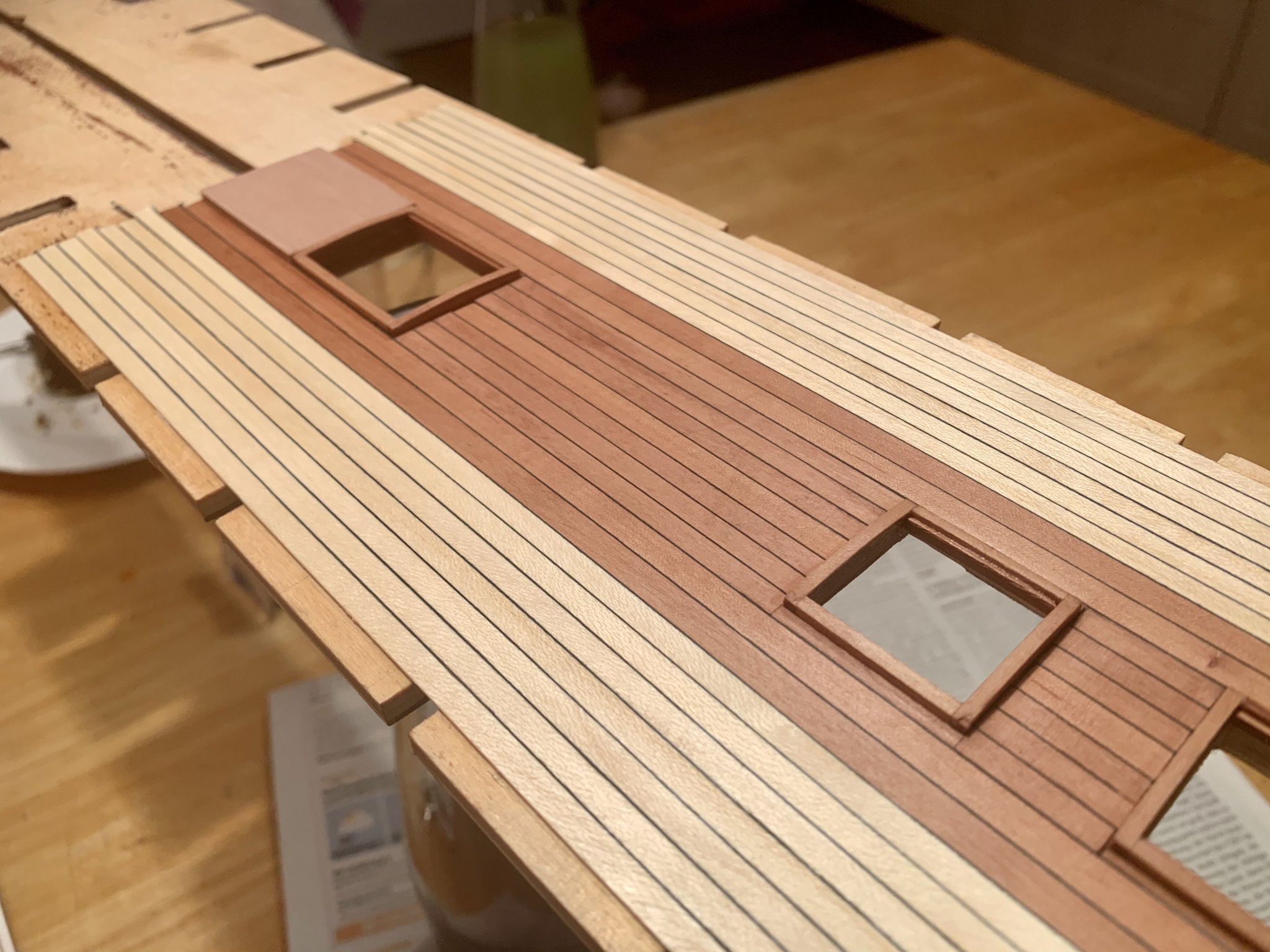
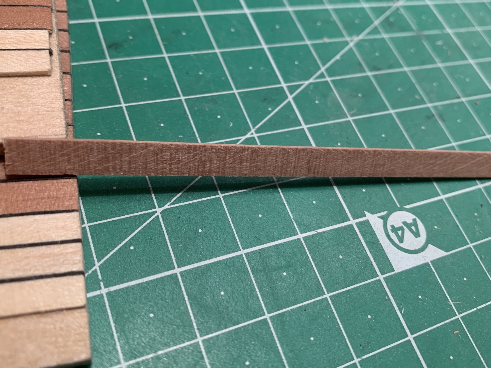
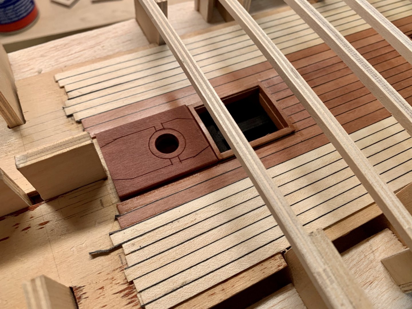
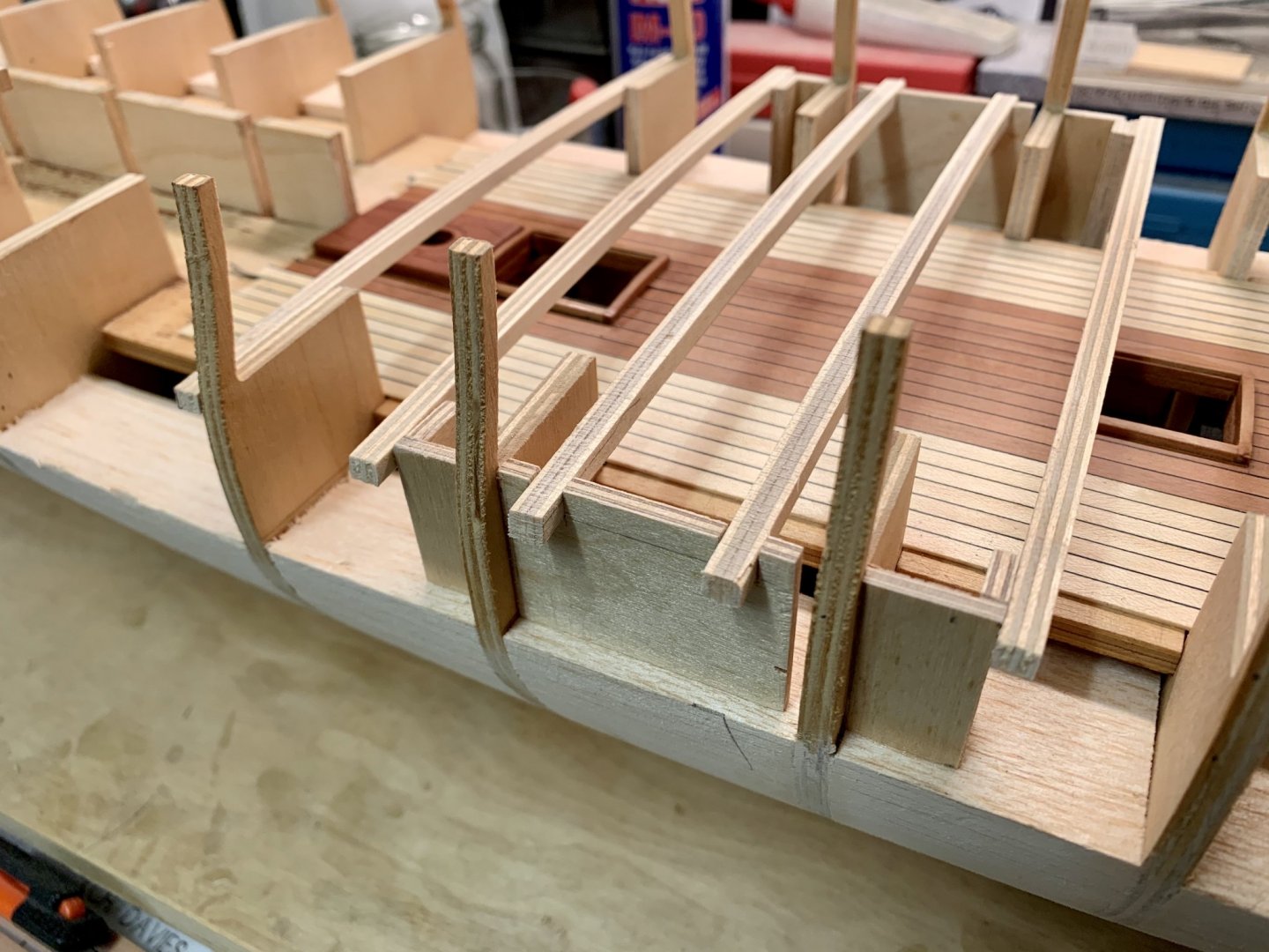
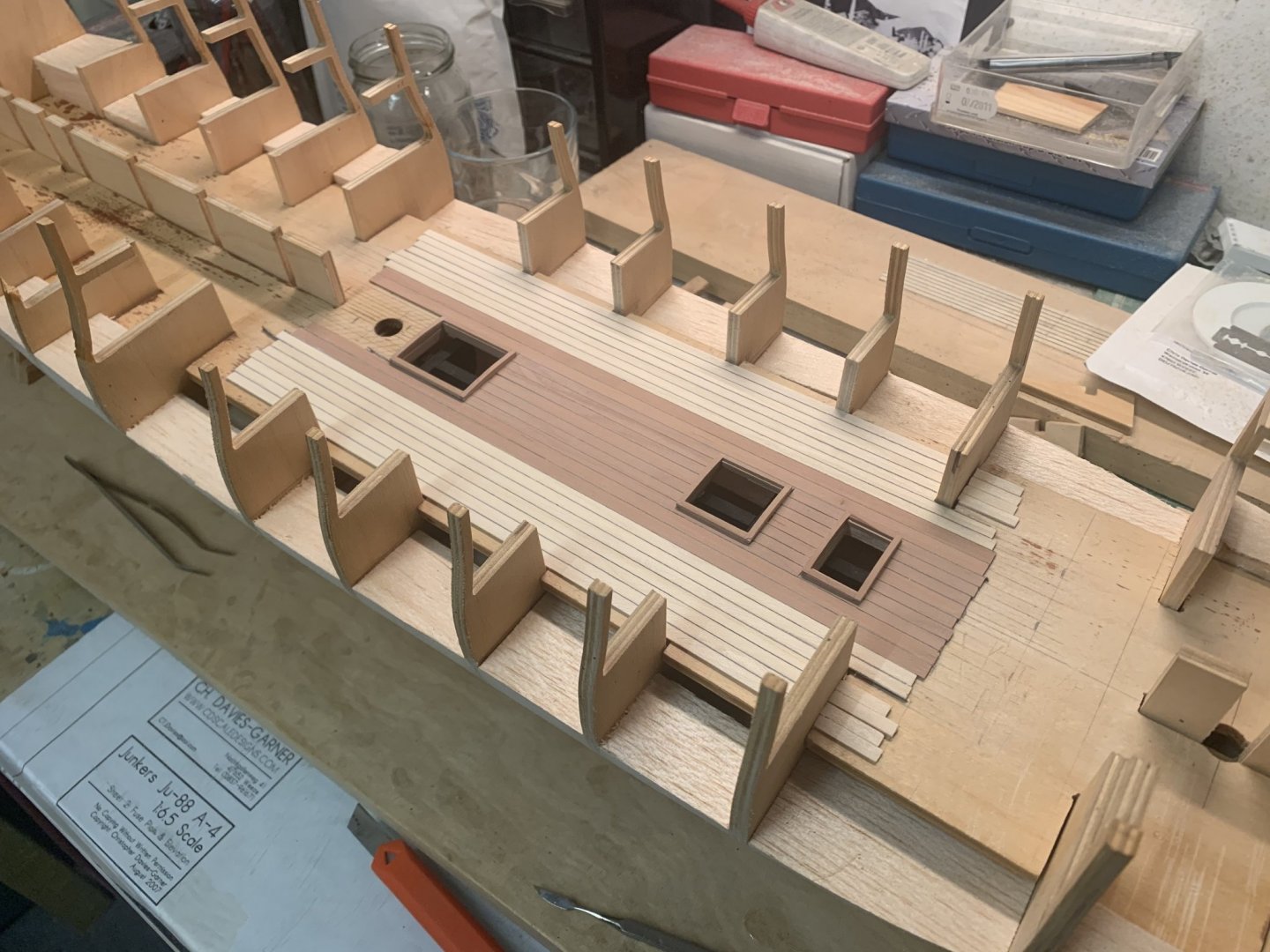
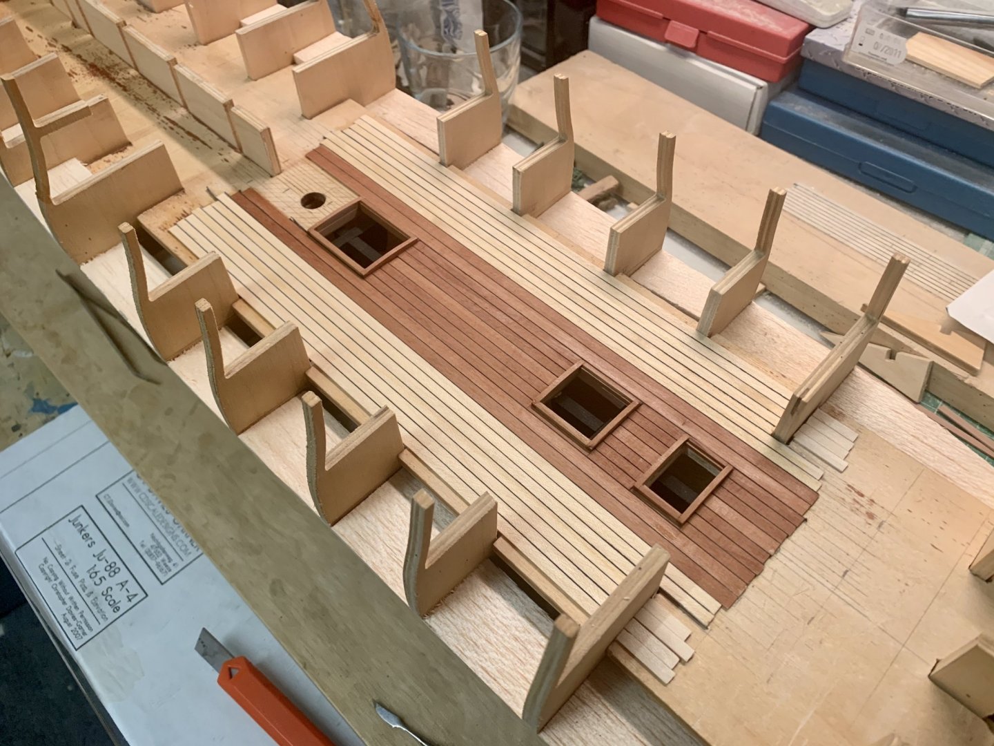
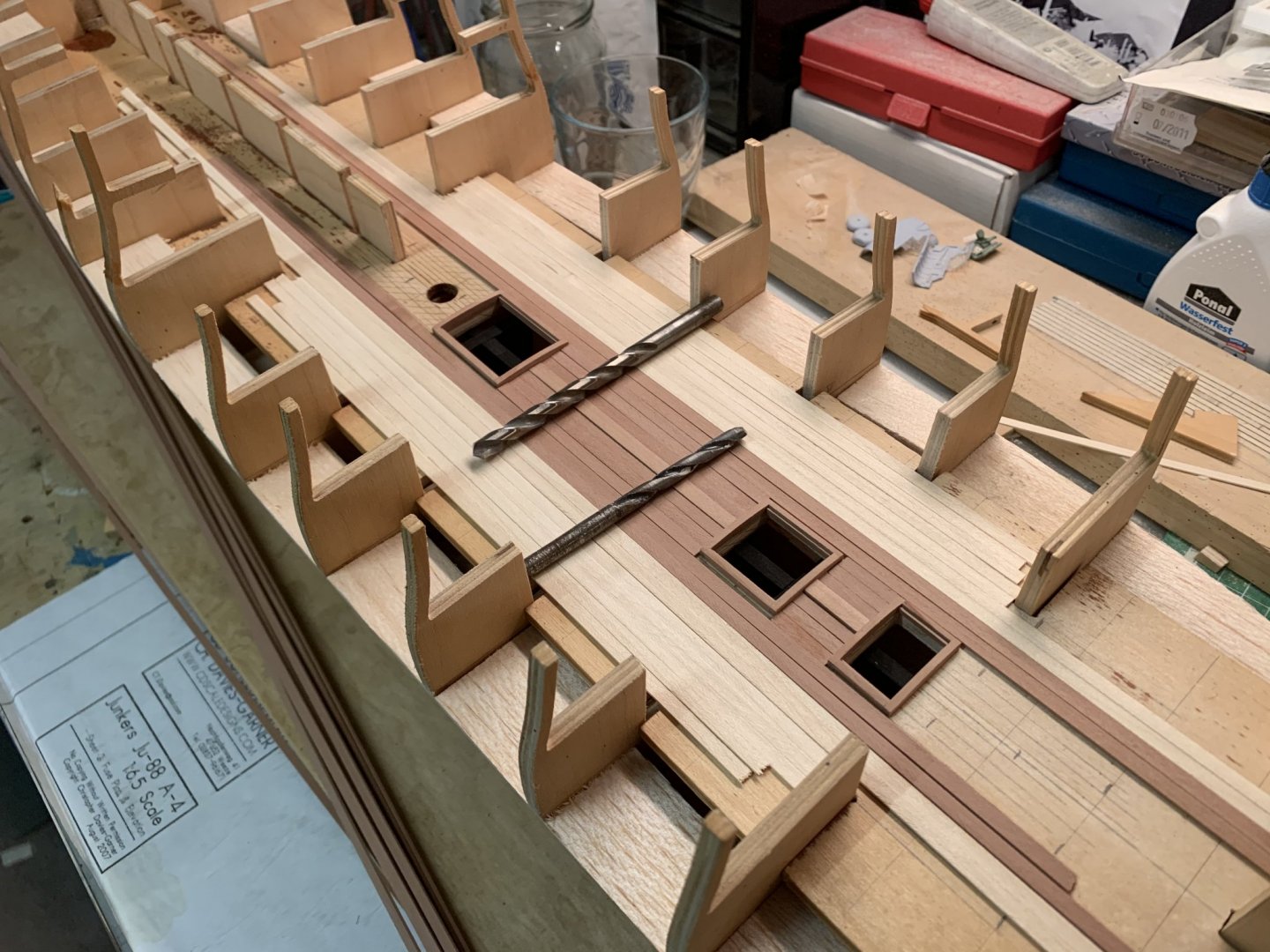
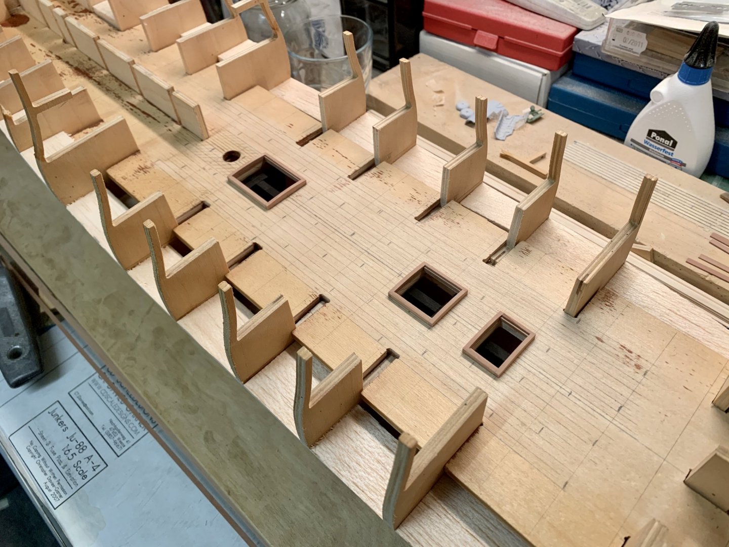
Update! The sides of the other hatches have been lined with thinned pear wood strips to conceal the ply deck which was nearly white. The main mast partner was made from one piece of 3mm pear wood. I use a technique from the plastic model guys here, panel line scribing, to make it look like several parts. This will probably work here as it will be hardly visible tucked away in the catacombs of the lower deck. One or two more coats of oil are still needed here. This is when disaster struck. The wood oil had settled down to an even but matt finish after a week so I decided to give the deck one more coat. Without really looking I grabbed the can of grain filler and only noticed it when I had finished. Duh! The whole deck was sanded down again but the filler had still penetrated the wood to some degree, so after another coat of oil the finish was not as smooth and even as it used to be. I‘ll leave it for another week to see how it looks then. Going through Beef Wellington‘s thread I saw the deck beams, parts 7a, 8a and 9a. These are shown on the drawings but not mentioned in the text so I nearly missed them. They are, however, not all the the correct locations. They should line up with the ends of the hatches and two need to be added at the centres. For this new attachments needed to be made. I‘ve ordered 5mm pear wood to replace the plywood beams. Some tweaking is still needed here Thanks for looking, chris

-
I know what you mean ccoyle, but the darker wood (oiled or waxed pear wood) is actually more authentic as these ships were built from oak. I like the look of the darker wood as it is just as I would imagine that oak would have looked back then. The gun deck will also be done in waxed pear wood with dark grey paper caulking. I‘ve seen so many nice looking models with lovely box wood deck planking which actually isn‘t authentic. Also, the hatch coamings are then done in walnut to make the whole thing look like a gorgeous furniture piece which is IMO totally wrong. IF I am correct everything was done in oak back then so I‘m going to do everything in oiled pear wood
-
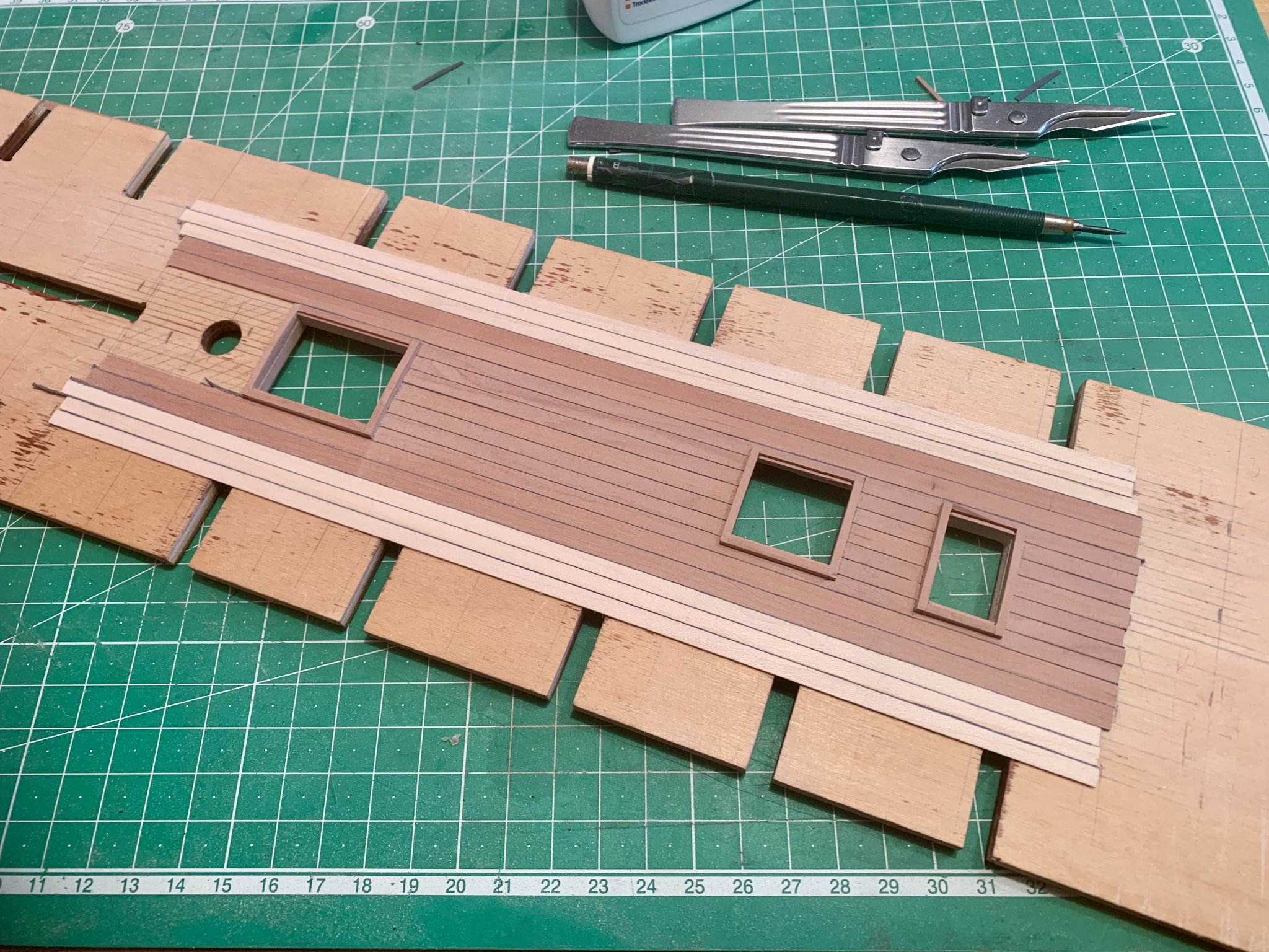
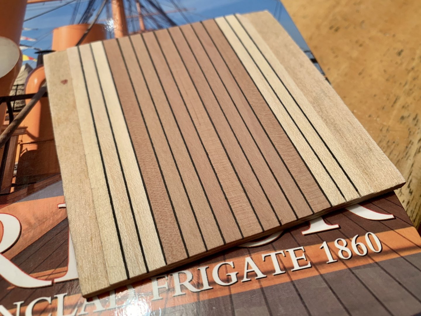
Yes! Getting close now! The cardboard strips were cut down to the deck planks with a small narrow Stanley knife, but still had to be sanded down to get them really flush. In the end I used 40 grit wet’n’dry stuck to small square pieces of three ply as everything else was just too tedious. Yesterday I applied the first coat of oil and let it set for 24 hours. I found a blog on the internet (in German) where someone really went into the details of using this stuff and wrote that using 240 grit towards the end leaves a matt and 360 a shiny finish. So today I used 240 grit and I‘m happy to say that I‘m very happy with the results so far. It‘s easy to see (maybe not on thevpictures) that the sheen actually comes from the wood and not just a varnish or lacquer that was slammed all over it. I am getting very close to that surface finish I‘ve been hoping to find. Tomorrow I‘ll try 360 grit to remove some last blemishes and (hopefully) get an even smoother finish. Good night, Chris, in Germany
-
The rest of the Fir planks have been added, at least as far as I want to go with them. Test to see how it all fits. The first layer of oil (or wax or whatever it is) has been applied. On the bottle it says: apply one layer with soft brush (did that), wipe away excess with clean cloth (did that), repeat three times. Leave one day between each coat/layer. Ho-hum... ...I think I’ll go and watch Master and Commander

-
Halfway there. I want to add some more Fir strips and nothing has been oil stained yet. I‘ve had that Coldplay song in my mind all morning: “Nobody said it was easy...” You don’t have to thank me for the ear worm 😁

-
Tosti writes in his Naiad books that the planking outside of the Binding Strakes was done in Evergreen Fir, but only on the lower deck as there wasn‘t much wear there as it was where the crew slept and there were no heavy cannons to move around. Today I spent the whole evening sanding the deck planks smooth. Although this isn‘t right. I think the strips should only need some light sanding prior to planking but the saw marks are quite noticeable. tomorrow I can start glueing and caulking. Thanks for stopping by, Chris, in Germany

-
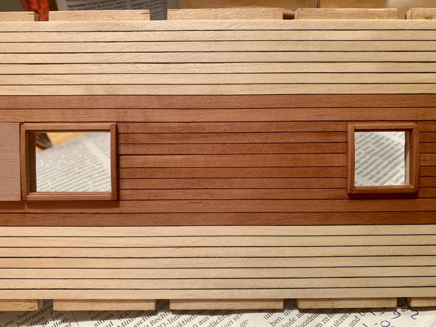
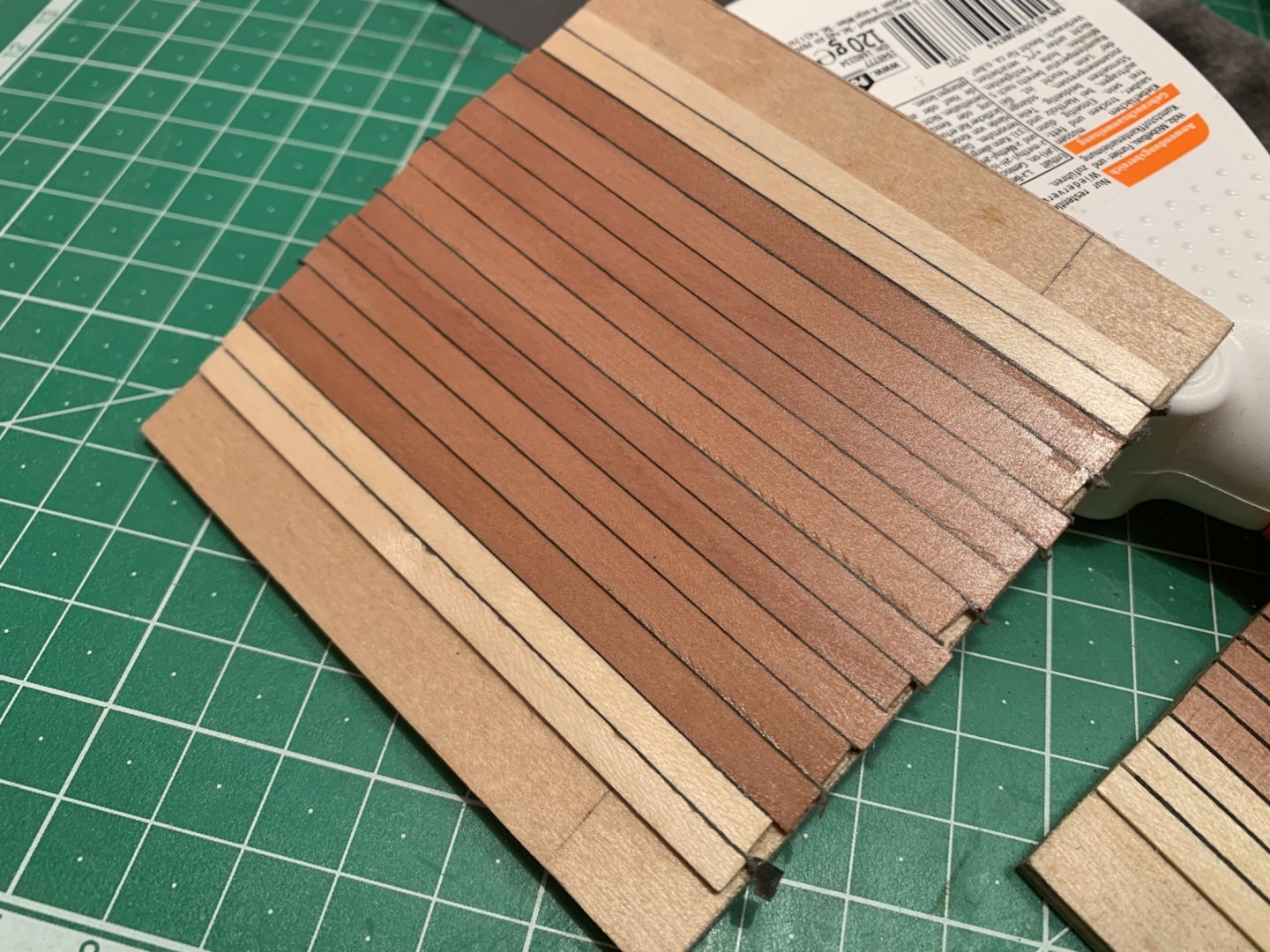
I think I finally might be heading the right way. Third sample: first of all, dark grey paper caulking stands proud of the deck planking. After I had trimmed down the caulking I had realised that the planking strips were of a different thickness. The wider strips which should represent the king plank and the binding strakes were thinner than the others. Just an oversight on my side. Mental note for the next time, or real planking: check the planking strip thicknesses before glueing! The wood here is oiled. Looks much better than the airbrushed grain filler and is much easier to deal with. So, I‘m happy with the caulking and the oiled planking strips. Might be getting there soon after all. Chris, in Germany
-
Thanks for your comments Beef and Teloo, very kind. I‘m not sure yet if I‘m heading the right direction. A few lessons learnt on this latest sample: first, the deck planks must be sanded smooth before planking and the caulking paper strips must stand proud of the deck planks before sanding everything flat otherwise things just get too uneven. So, the caulking is a lot less conspicuous than before which is good, but I had to give the sample a few light coats of grain filler with an airbrush but now I‘m getting a slight shine which I would rather avoid. Is a wax layer and honing a solution?
-
I think I‘ll try dark grey paper next, see how that looks. My brother also agrees that the cardboard is too wide.
-
First the idea was to plank the deck. Then I thought, I might just as well do the hatches too. Then I read about the Evergreen Fir outside of the Binding Strakes. Then I thought I‘d try caulking... But really this is also a test prior to planking the upper decks chris
-
Even if the hatches are barely visible, and I think they will be, I would still want to do better here than just paint the deck in walnut brown. I started working on my Diana early December and I still haven‘t reached the end of the first chapter in the instructions manual yet 🤪

-
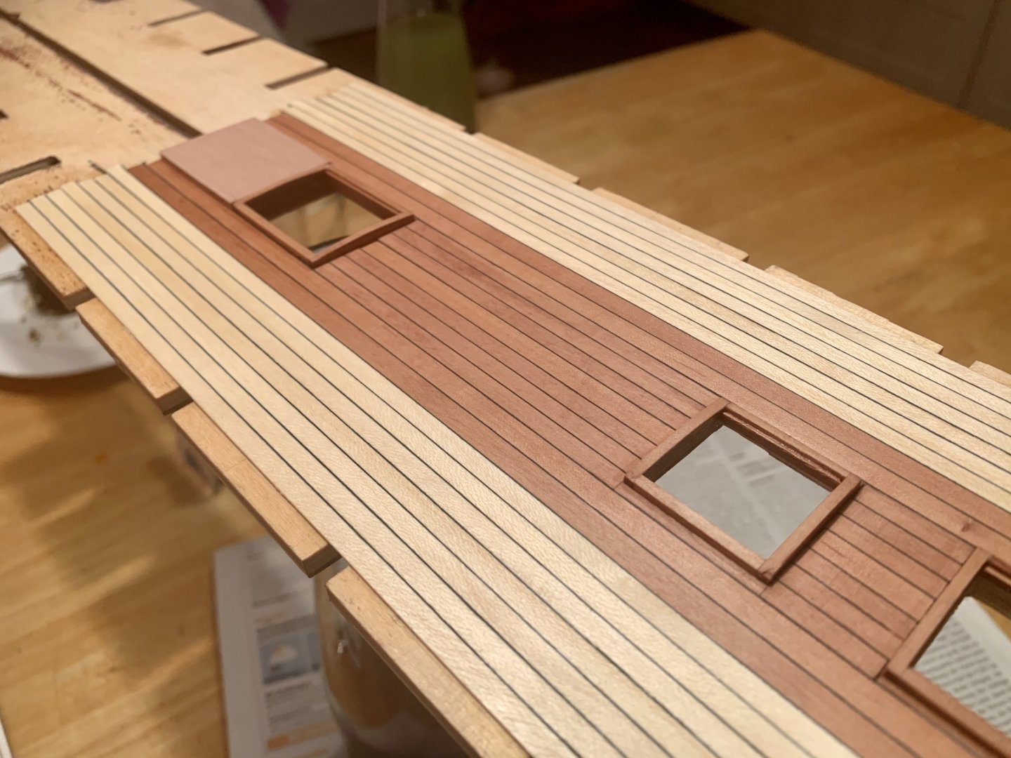
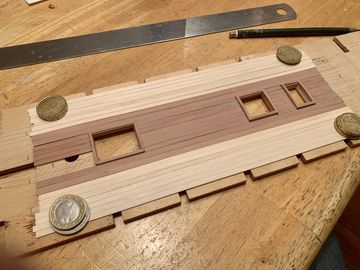
As you can see I have a wider King Plank in the middle a wider plank for the Binding Strakes, which should actually be two. Outside of these is where the fir planking starts, but only on the lower deck. My brother, who is an expert ship modeller mostly leaves his wood natural, but I‘m thinking of airbrushing(!) a fine mist of grain filler as some protection, as I‘m worried the untreated wood would pick up dust too easily especially in moist and humid conditions.
-
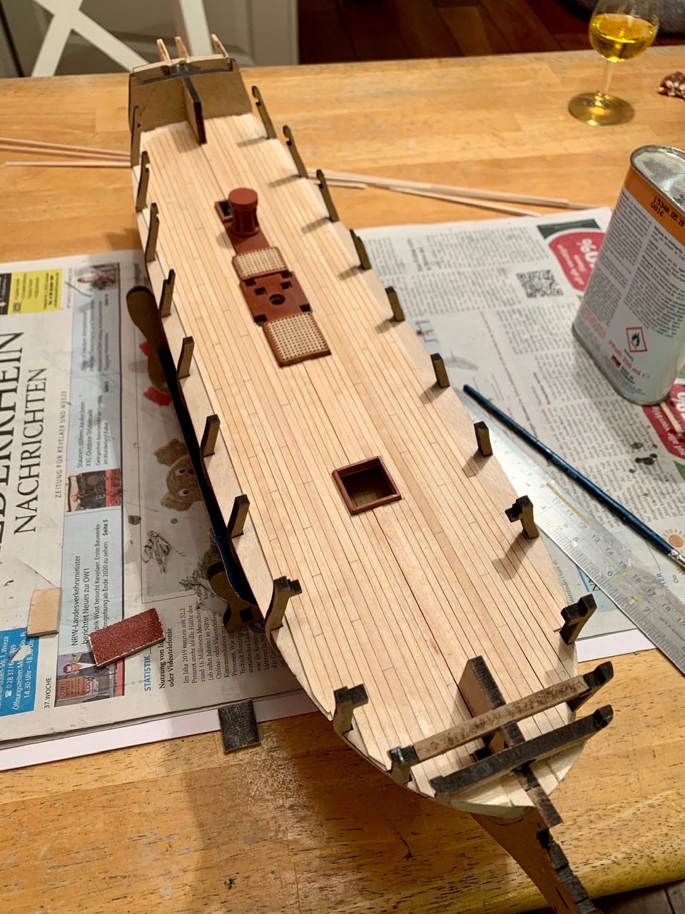
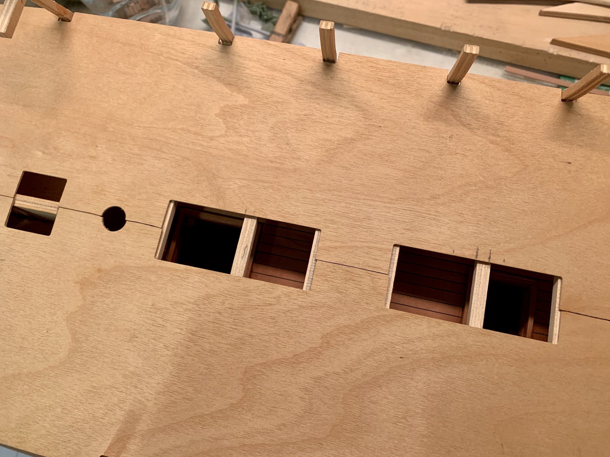
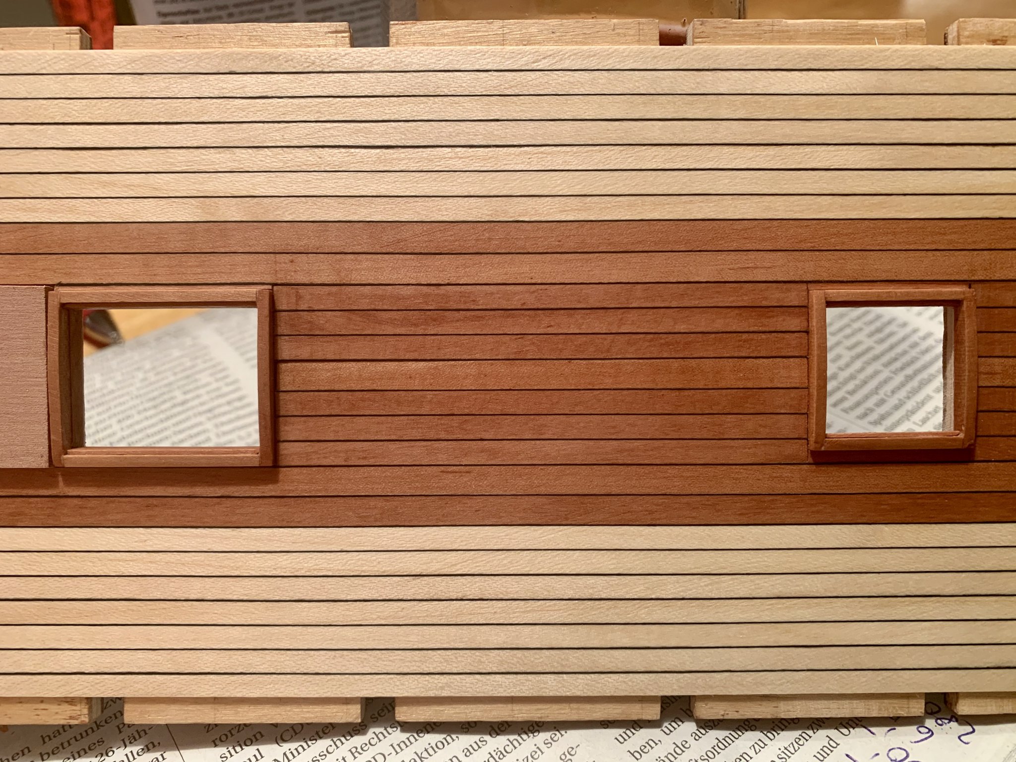
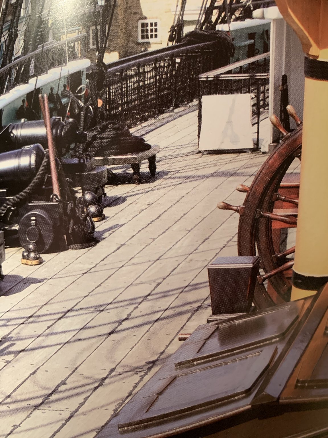
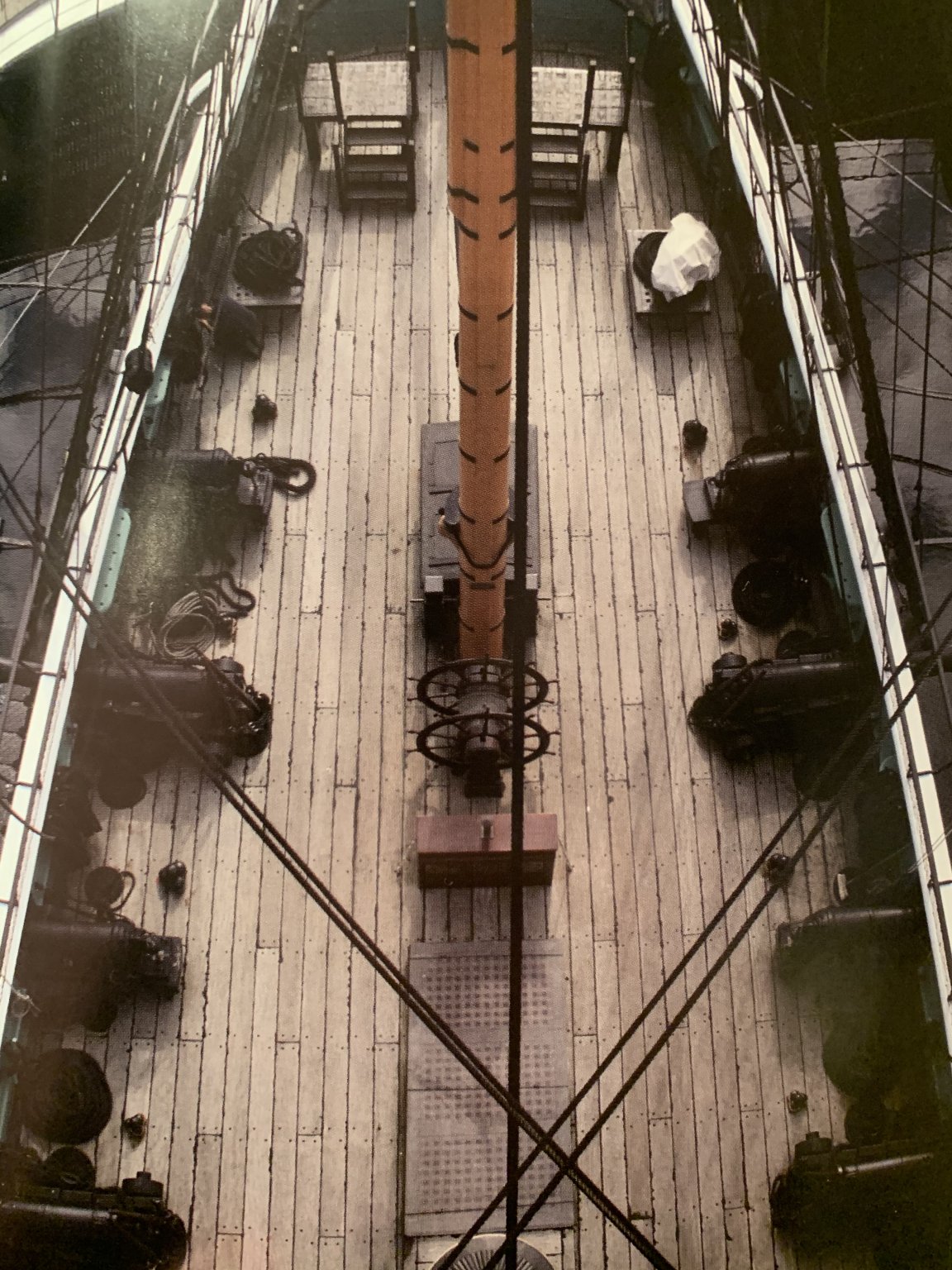
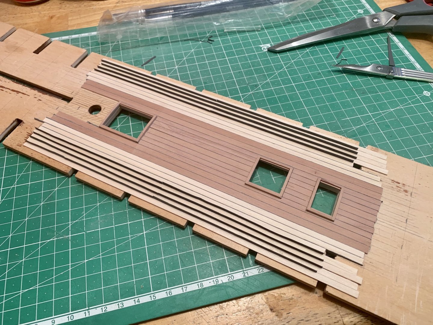
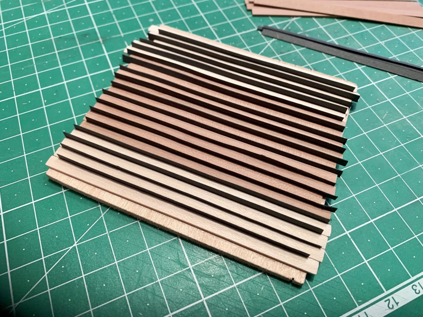
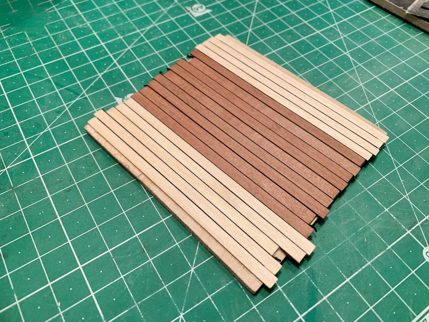
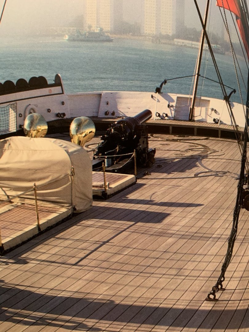
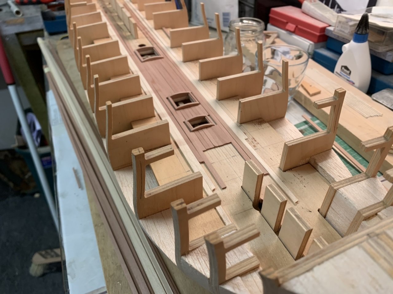
Small update, good evening all, I need your expert opinions here. With the hatch coamings sorted I‘ve been thinking about the lower deck planking. Some modelers have achieved great results with thin cardboard strips between each plank for the tar caulking. This is what I‘ve tried here... ...but I think the results might be a bit too heavy. On the real ship decks the caulking is a lot less conspicuous as you can see here: Quarter Deck HMS Warrior Upper Deck HMS Trincomalee Quarter Deck HMS Trincomalee I might even leave off the caulking all together as the Navy board models don‘t seem to have this feature. Or I might try dark grey paper. what do you think? Oh, yes. I lined the edges of the ply deck at the hatch openings as the ply wood which was almost white was too noticeable. Thanks for stopping by, Chris


-
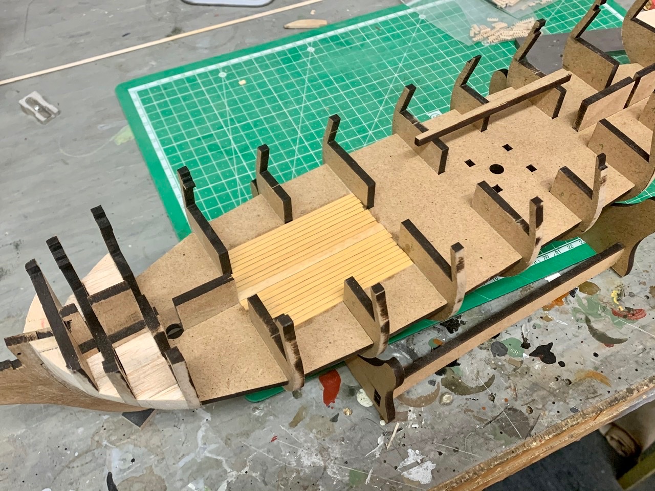
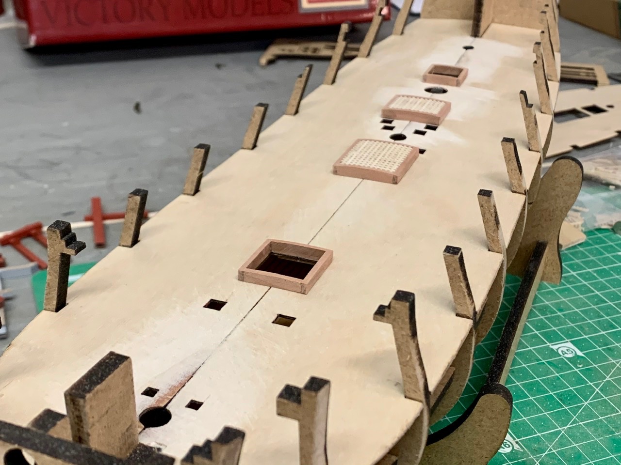
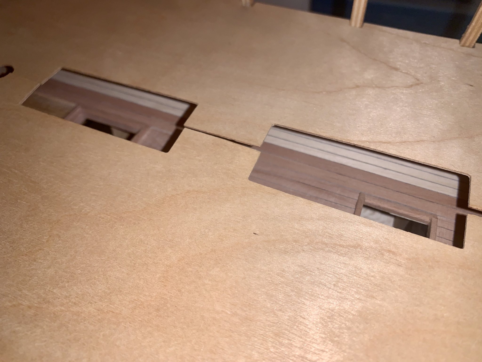
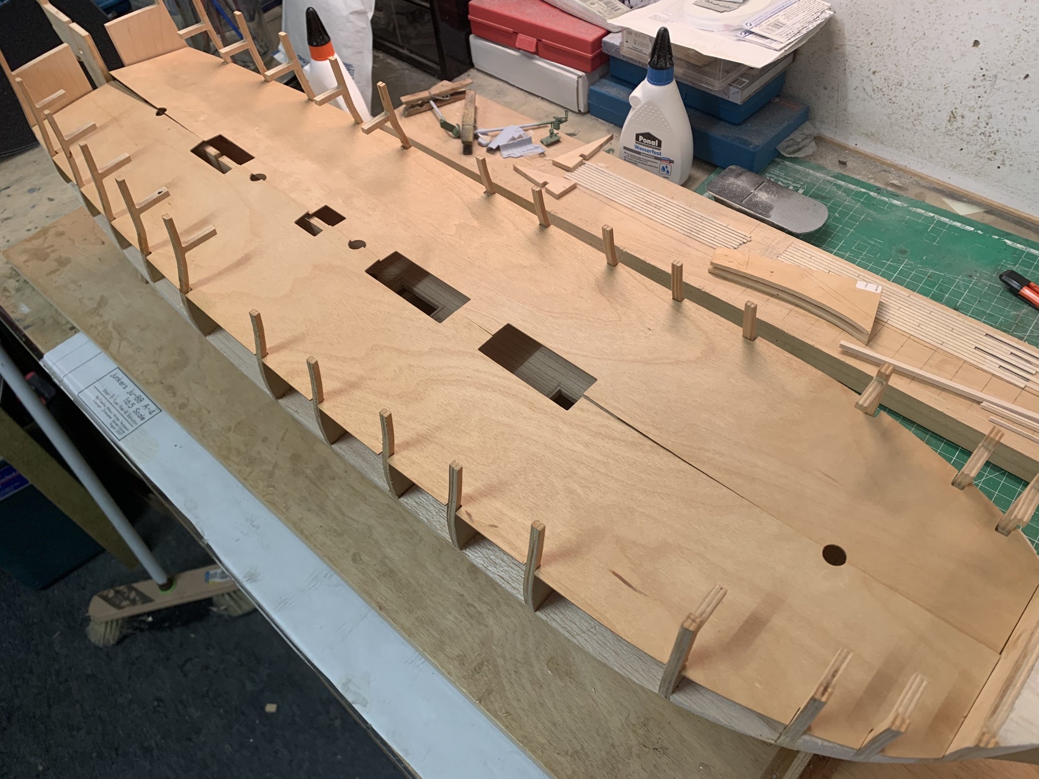
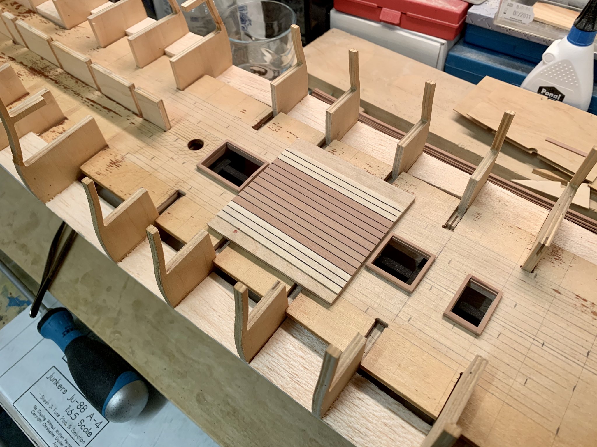
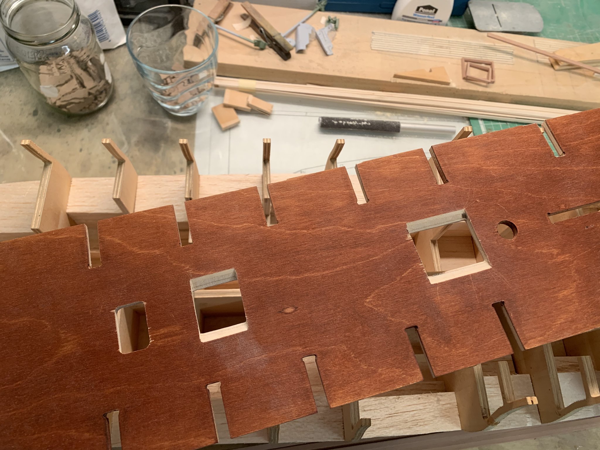
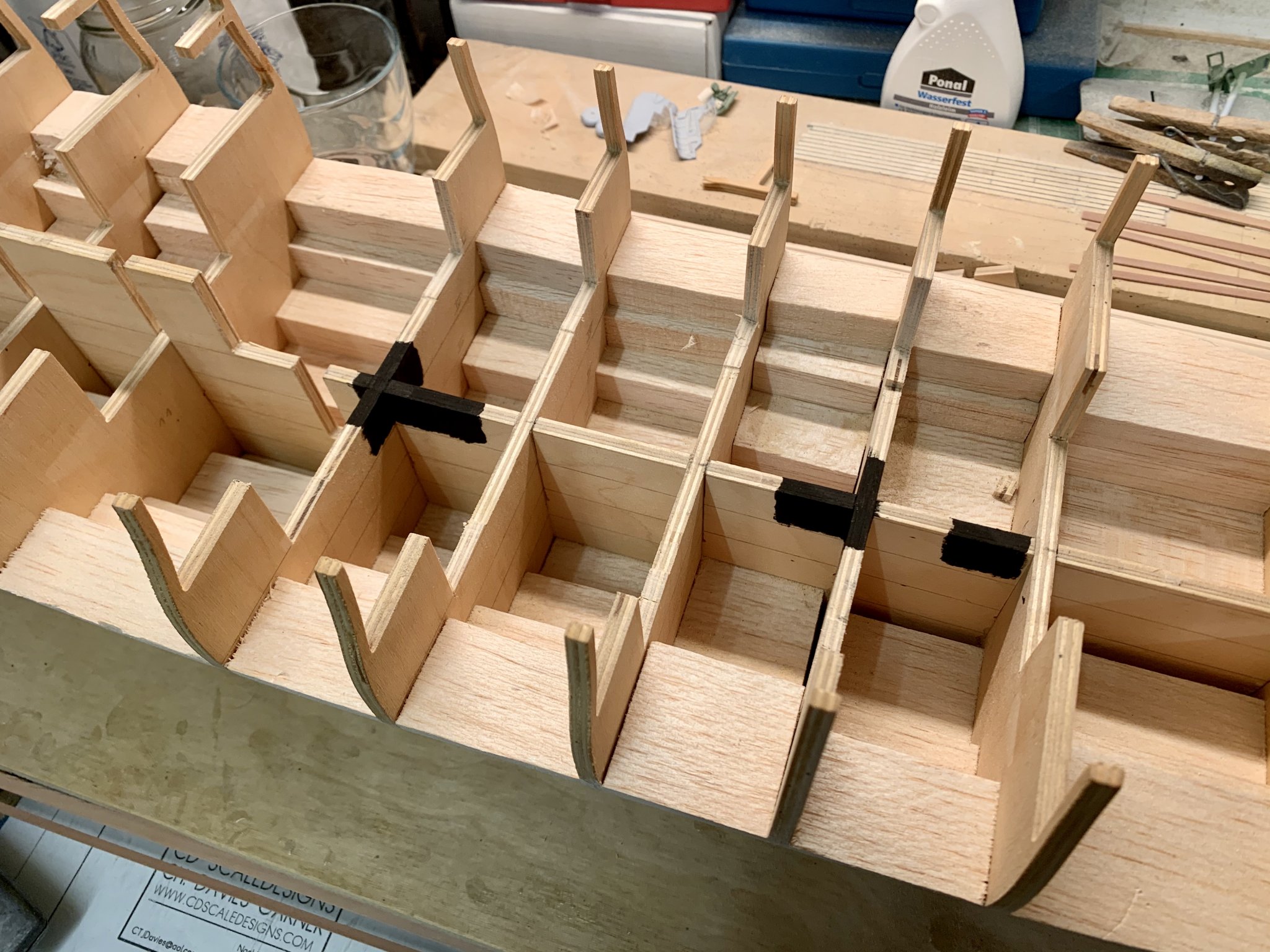
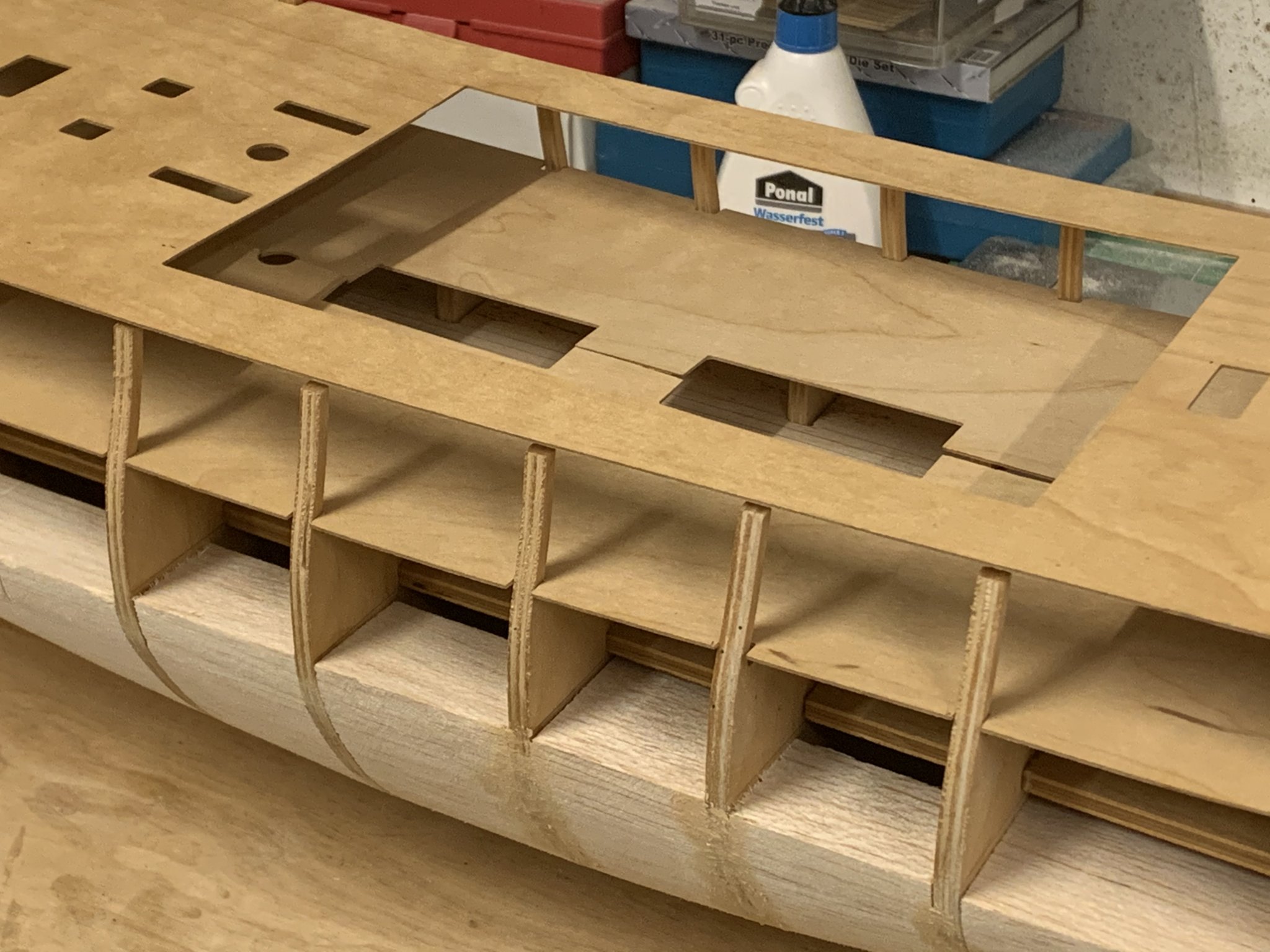
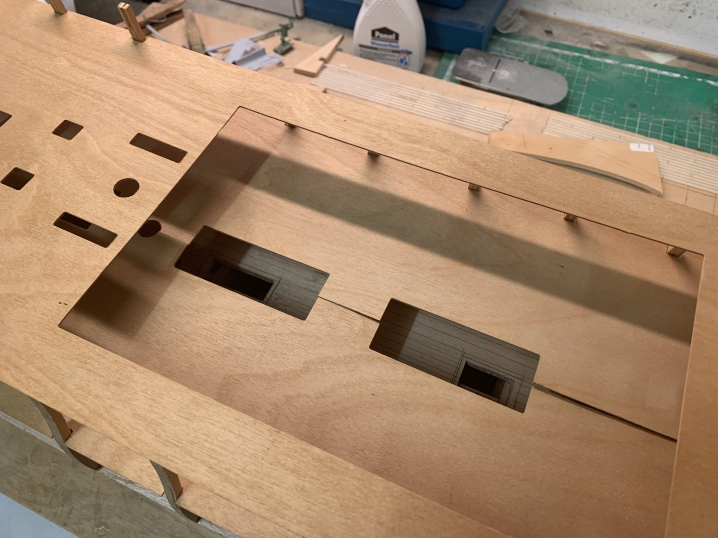
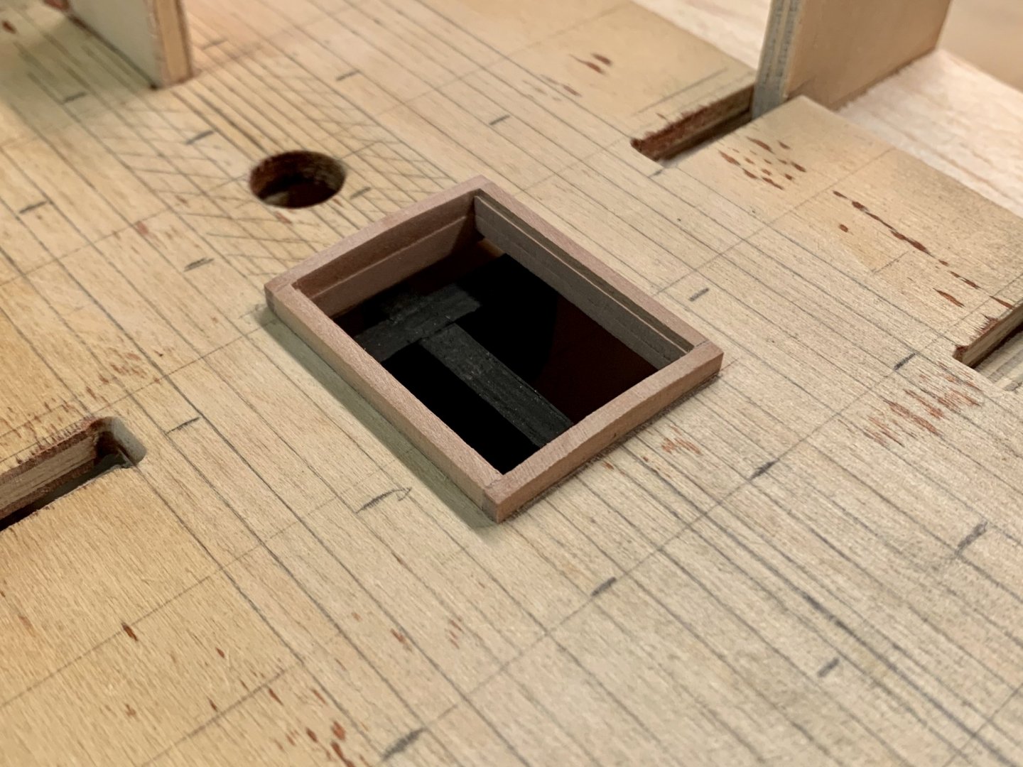
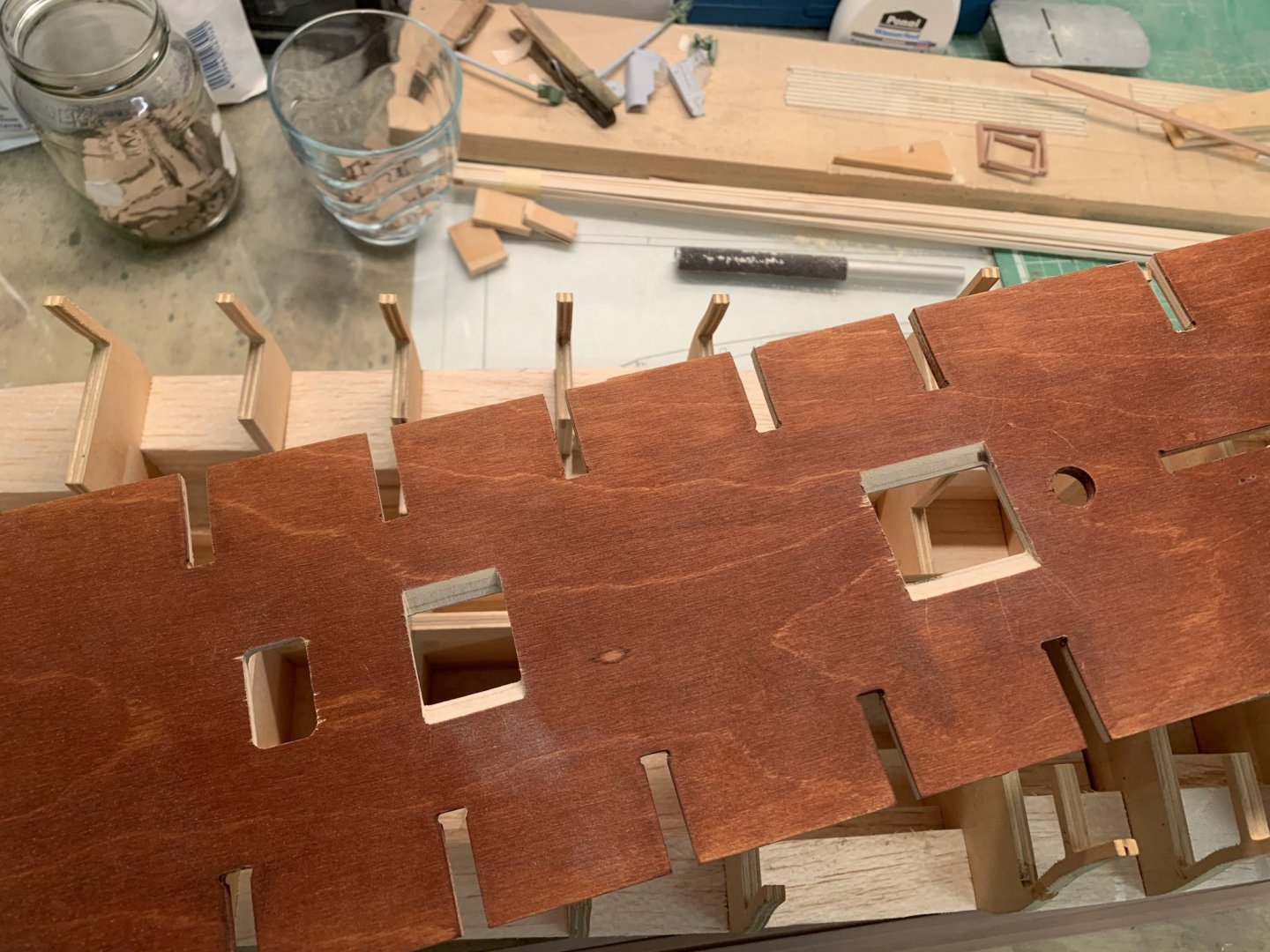
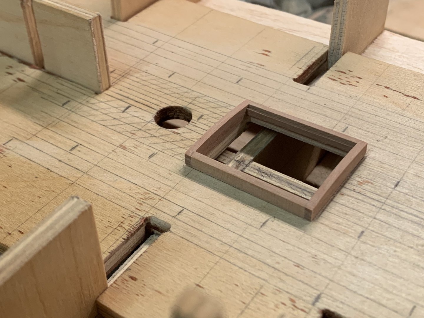
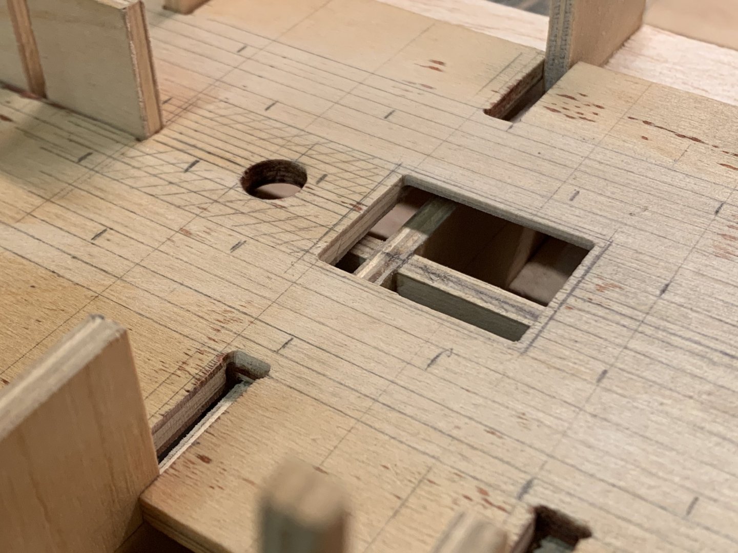
Good evening all, a small update. It took three attempts before I was happy with the hatch coamings. On this picture here the deck planks have again been loosely put in place, just for a sneak preview if you will. I cut away some large chunks from four bulkheads as I realized they would be visible from the upper deck hatches. That‘s the official version, but the truth is I wanted more deck area for planking. As I‘ve said before, Tosti writes that the planking outside of the Binding Strakes was done in Evergreen Fir. So cutting away the bulkheads would give me more space here. I didn’t want the deck to look as if it was 3‘ thick so I beveled the edges a bit. the PO had followed the instructions here and simply painted the lower deck in Walnut Stain. The bulkheads and false keel were painted black where the hatches are to make them a bit more inconspicuous when the gratings are added later Thanks for stopping by, Chris, in Germany

-
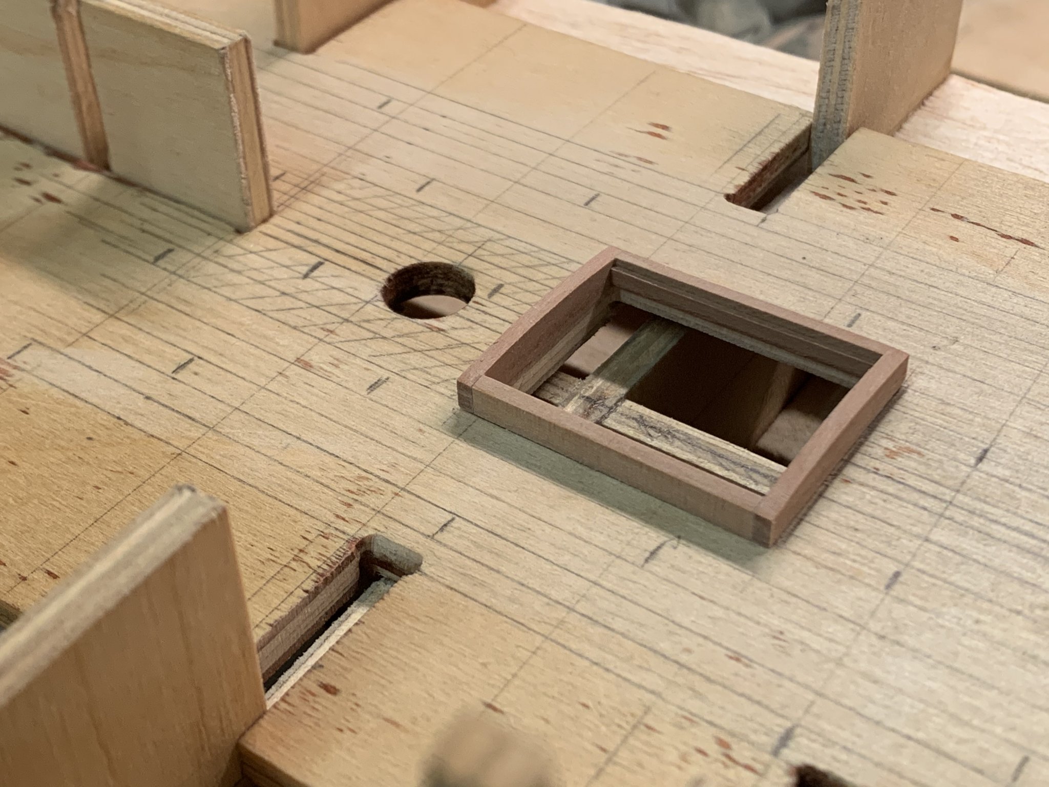
The wood for the lower deck arrived and I started testing my skills on some hatch frames. I think they should be a bit flatter. The deck planks are not glued here yet, just put in place for a sneak preview, sort of
-
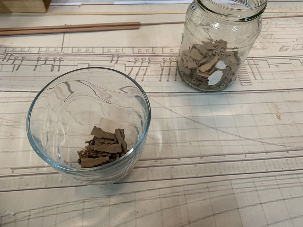
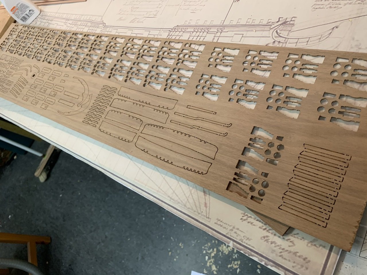
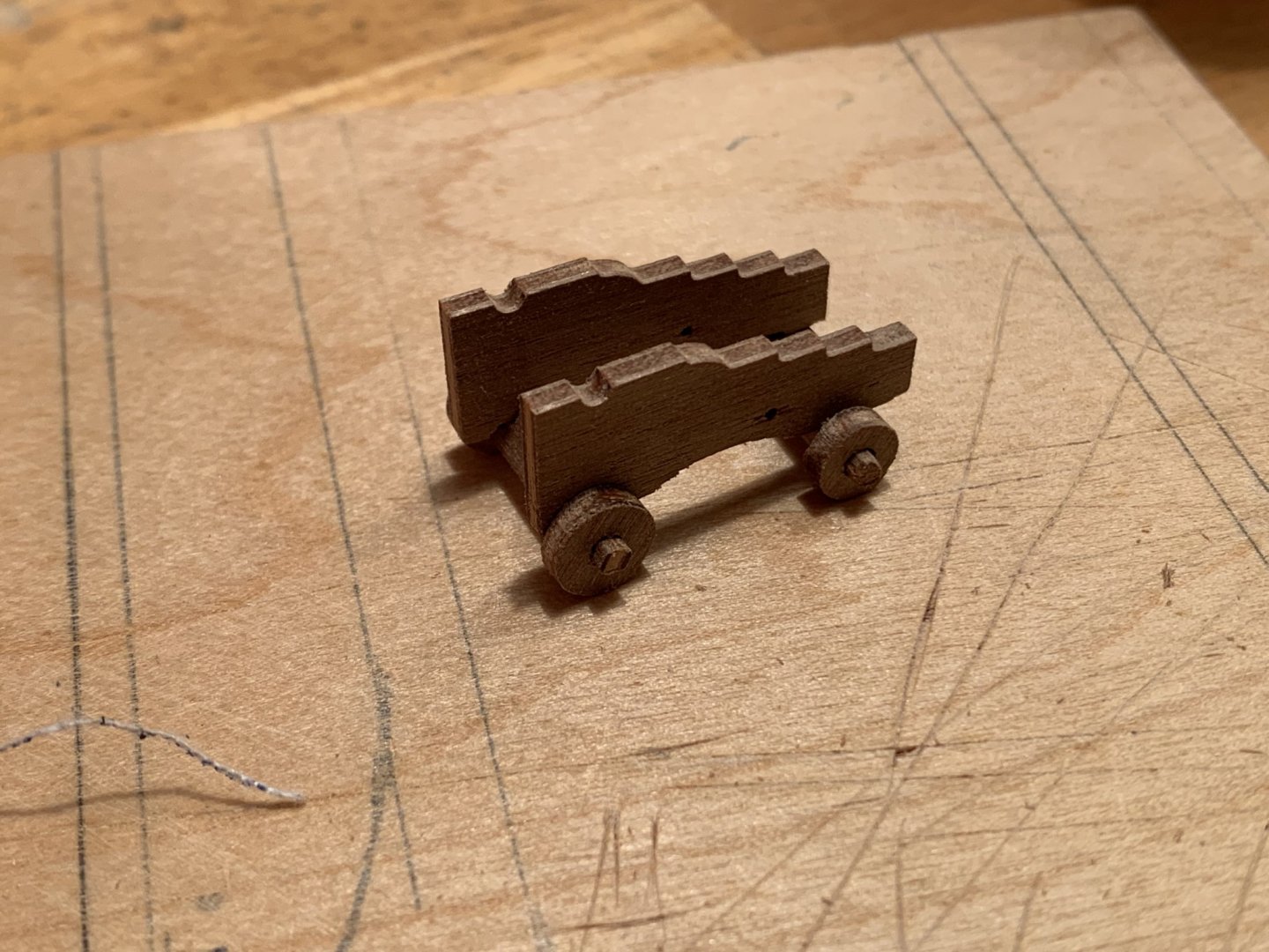
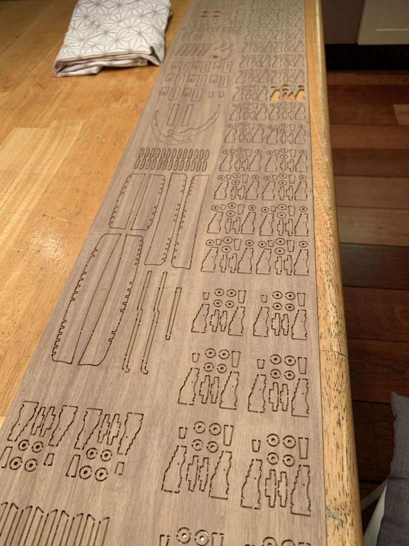
So after several hours I had cut out all the parts for the carriages. Not only did the tabs need removing, but there was a load of milling debris stuck to the edges which also took a while to clean up. I was about halfway through this all when I noticed that the cannons (and the carriages of course) were in two different sizes. So I spent an extra few hours sorting everything out again.
-
I‘ve ordered pearwood strips for the lower deck, which will probably only arrive the week after next. To keep myself busy I started something else. This is going to be a loooong build (well at least it isn‘t a Victory) 😳😆
-
I have also noticed that part of the bulkheads might be visible through the open hatches. This will have to be fixed. But first I‘ll have to order a decent razor saw. Per instructions the lower deck should just be painted in walnut stain, but I would like to take things to the next level here and plank the deck as far as it is visible and add hatches etc. Tosti writes that the planking outside of the Binding Strakes was done in Evergreen Fir which should add a bit of variety but only on the lower deck. As far as deck planking goes I‘m planning on doing everything in pearwood except the Fir decks which will be in Maple. Hull planking (if I get that far) will be Boxwood, Chris
-
I‘ve just noticed on my brother‘s PC that the images are very large. This might be against etiquette so give me a day or two and I‘ll see if I can replace them.
-
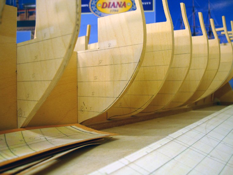
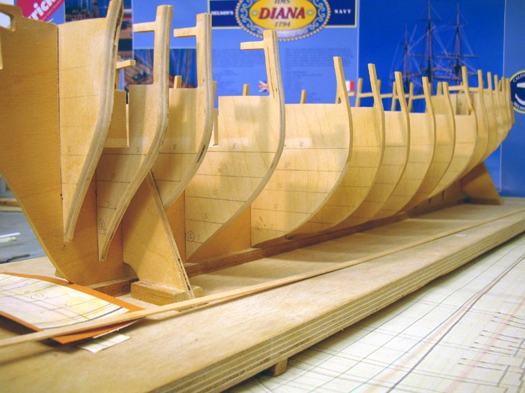
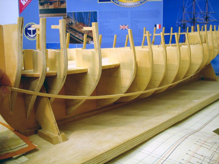
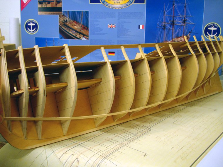
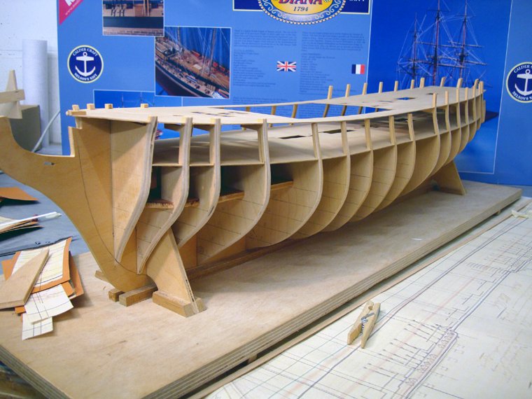
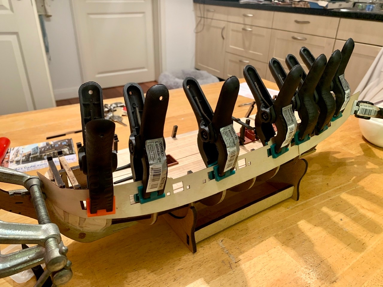
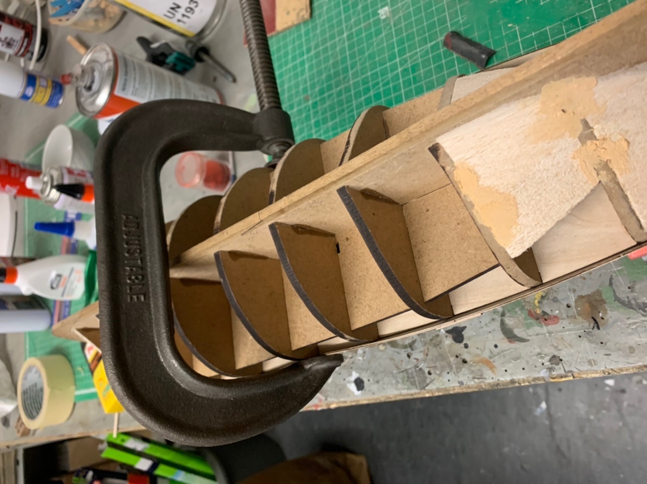
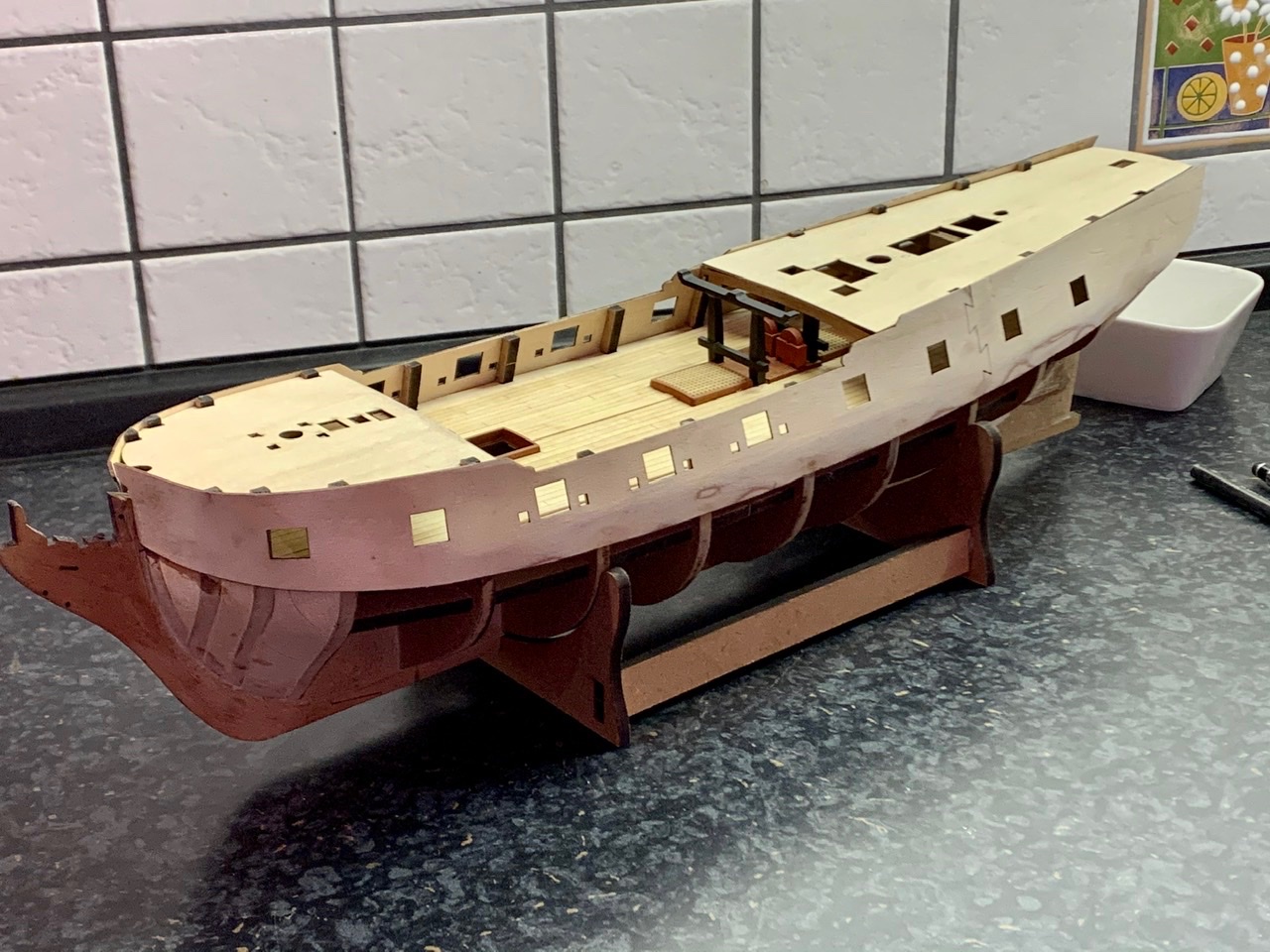
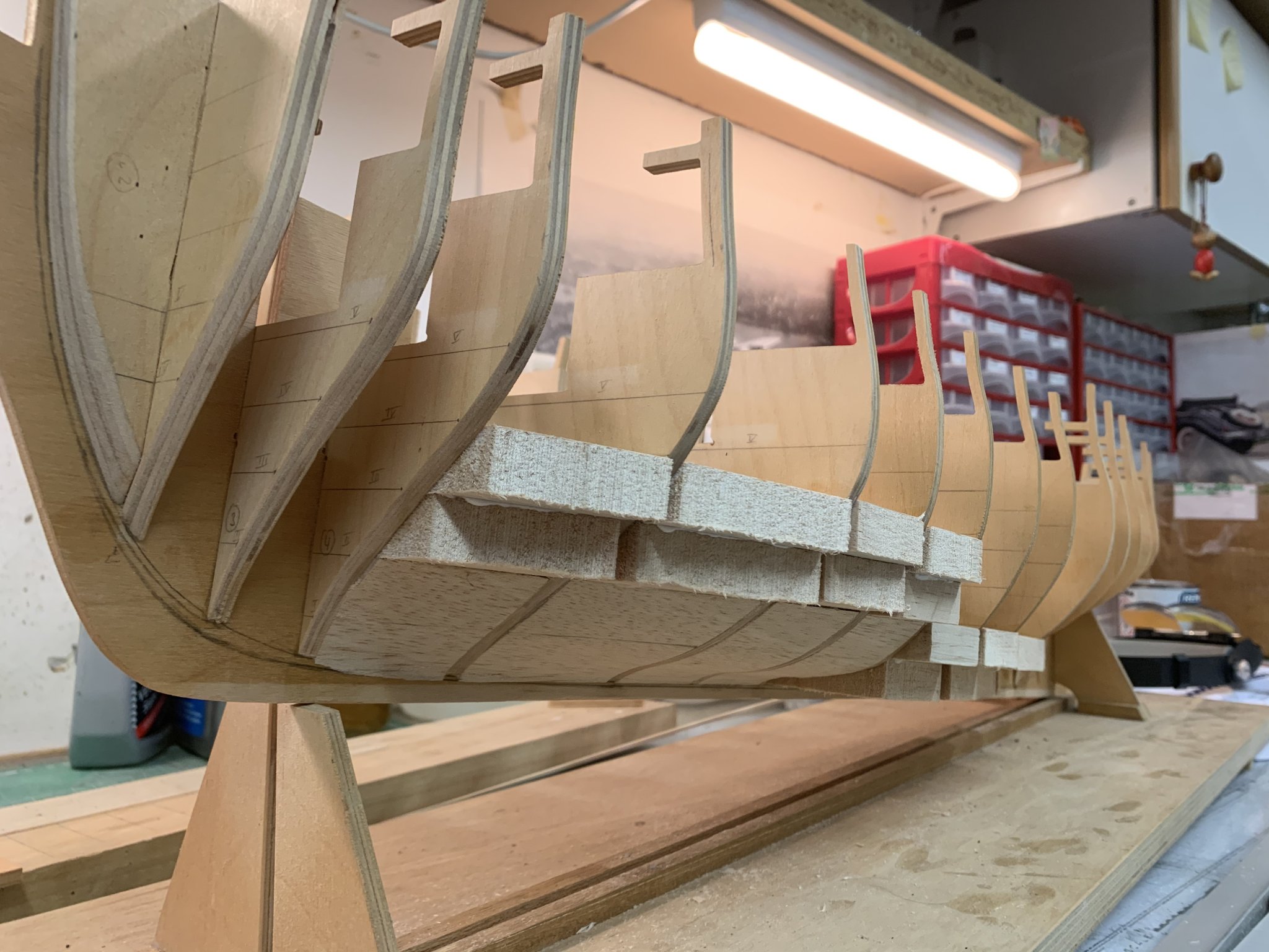
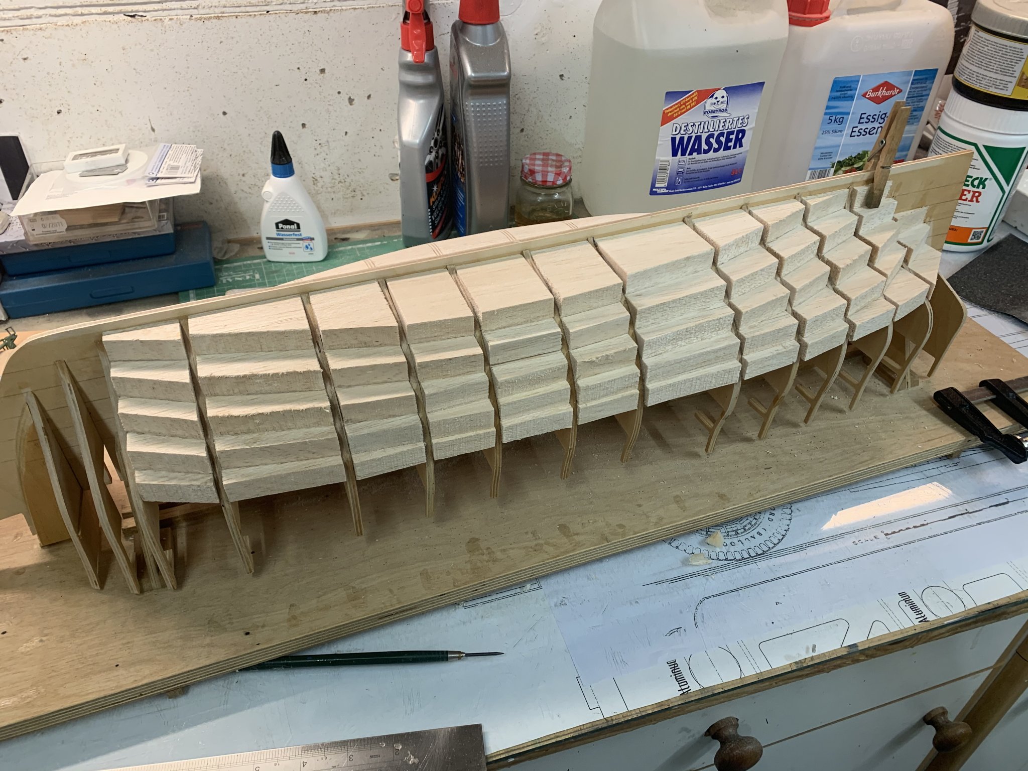
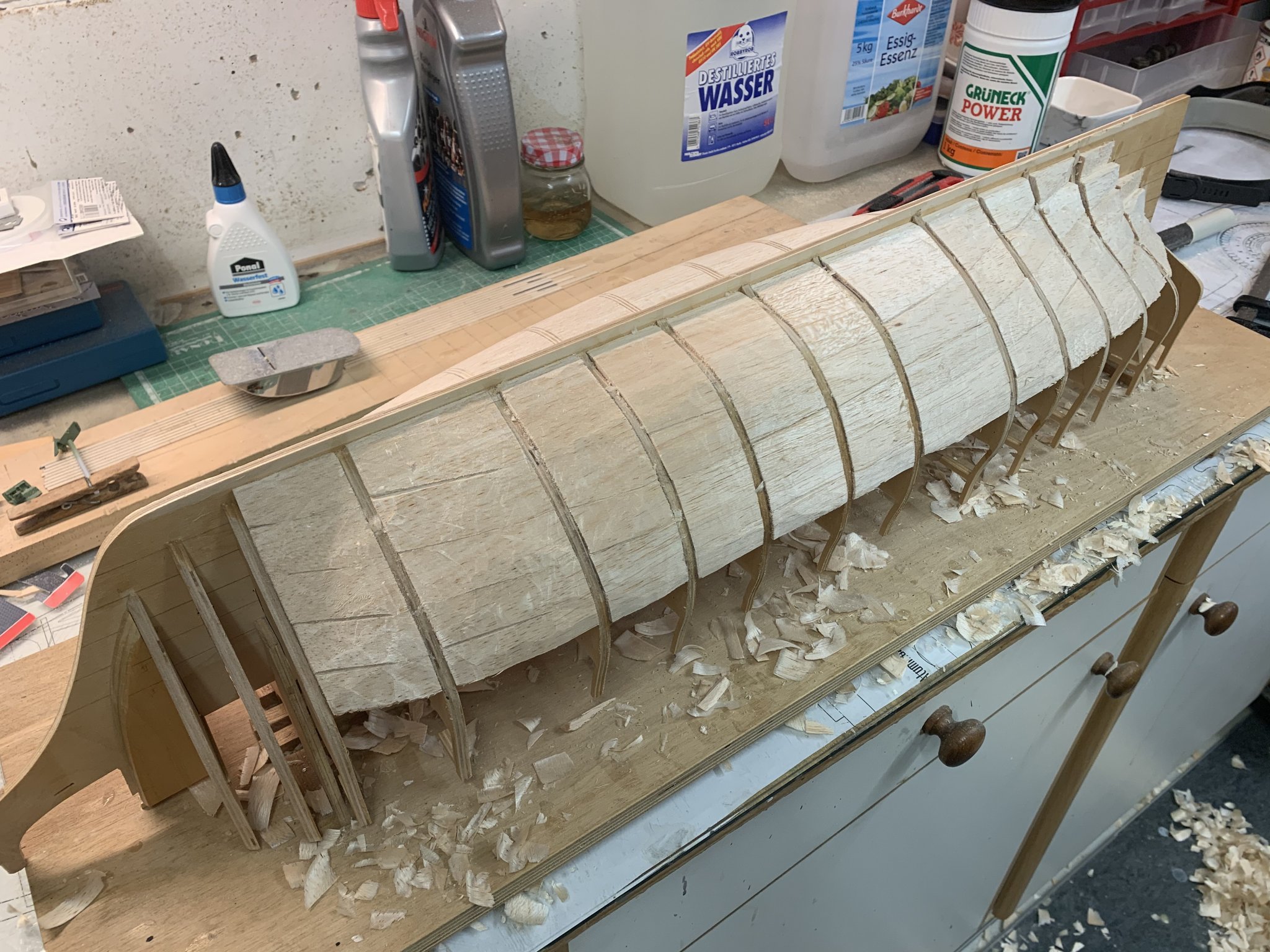
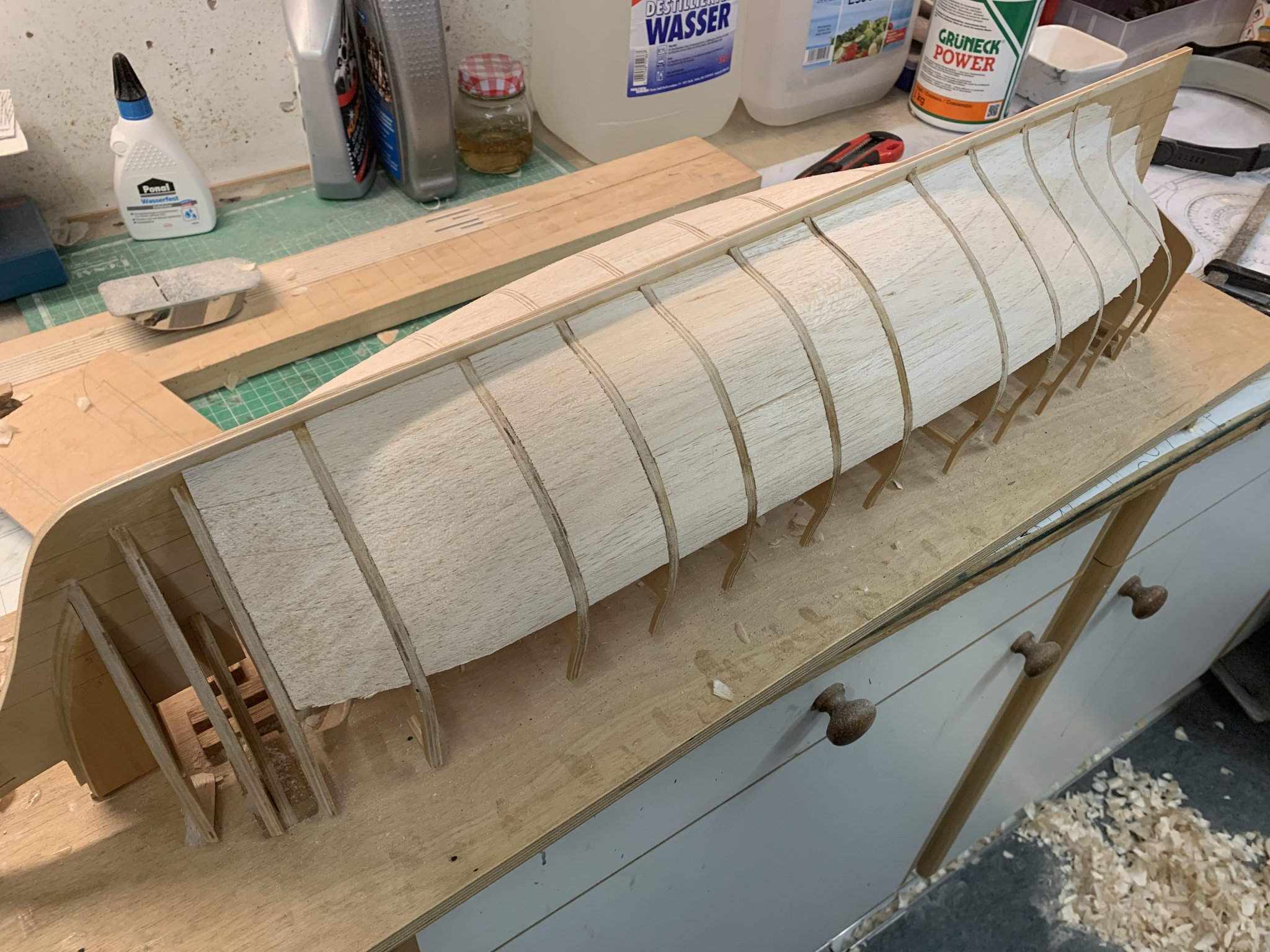
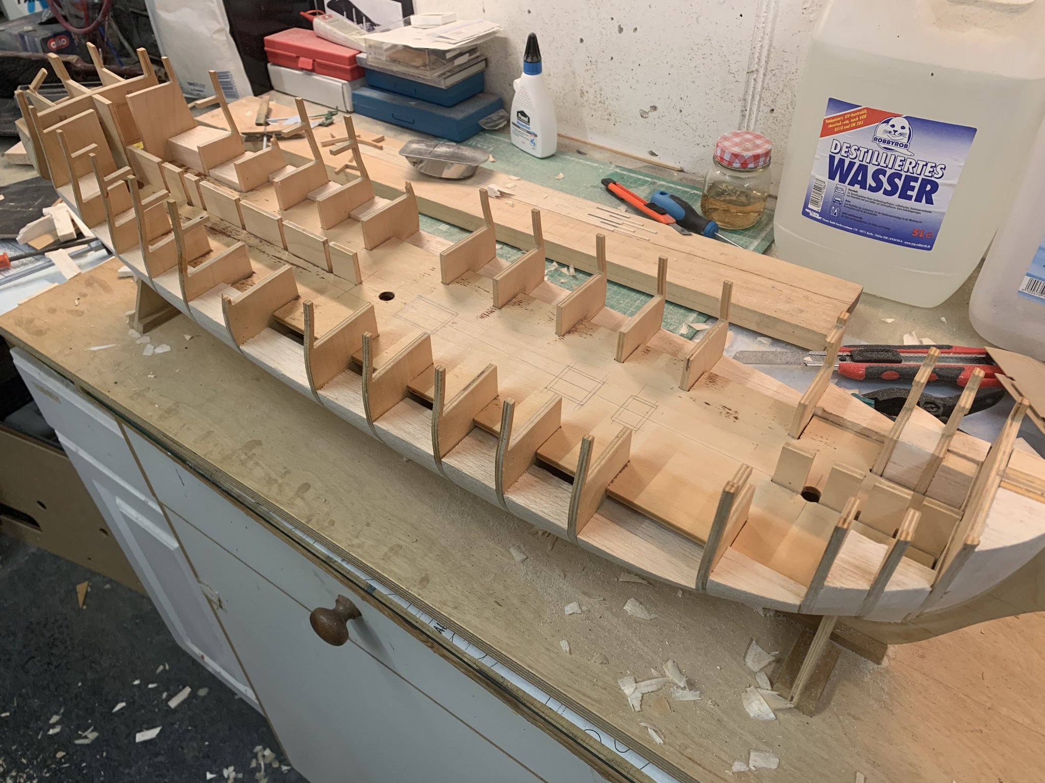
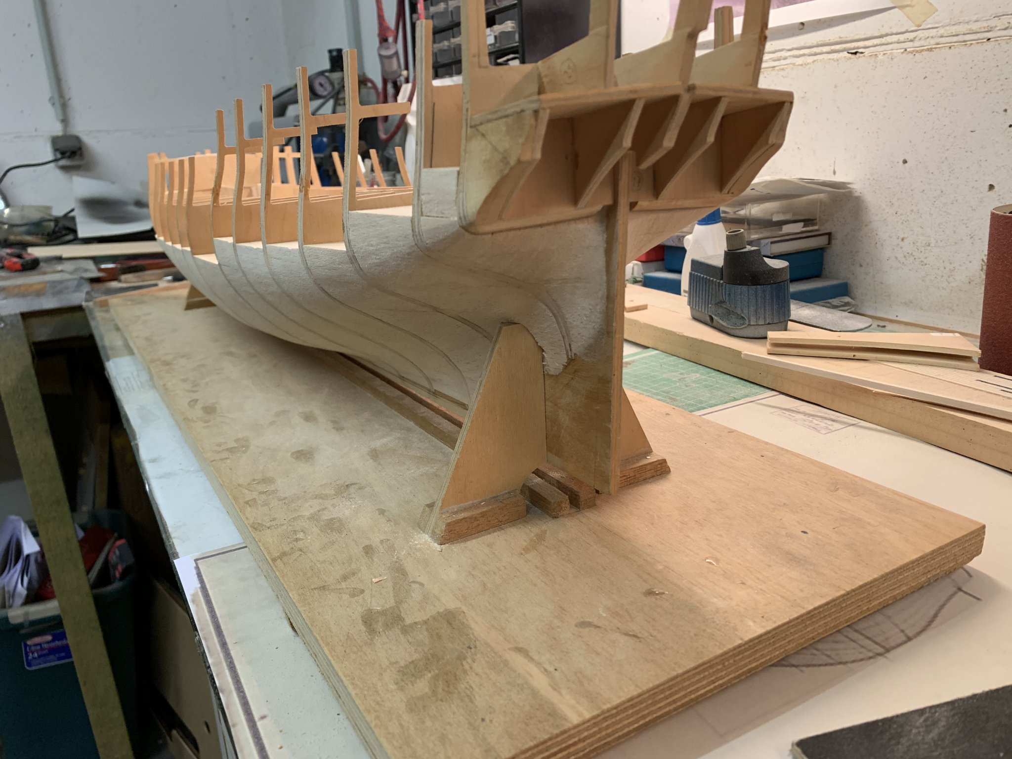
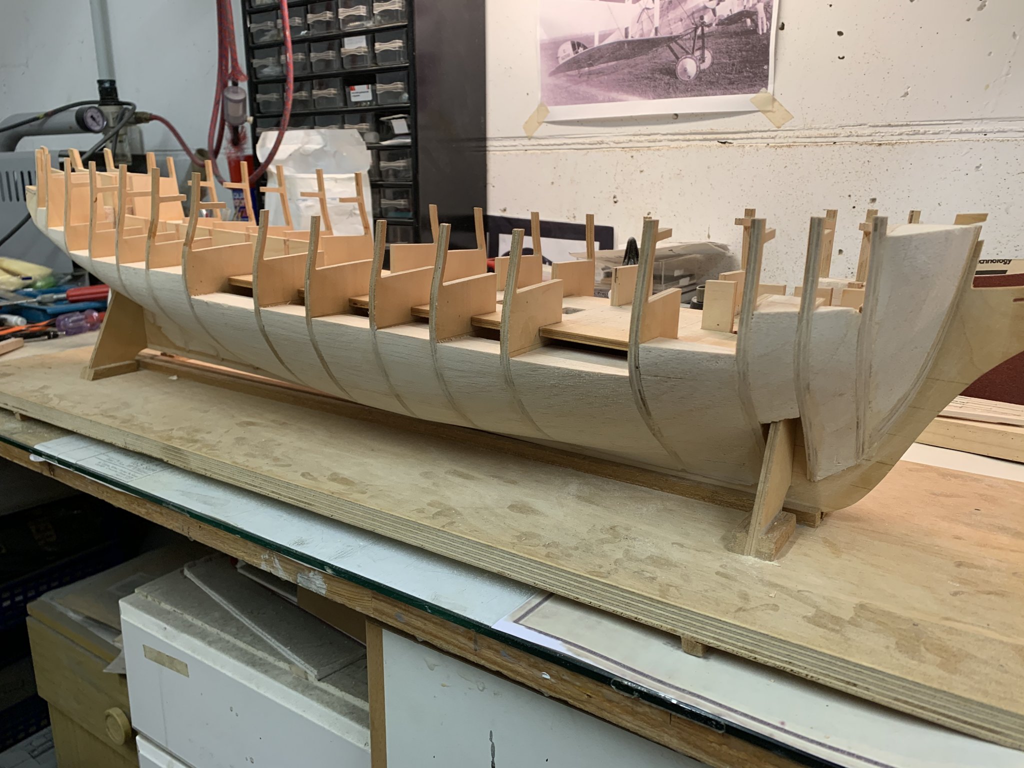
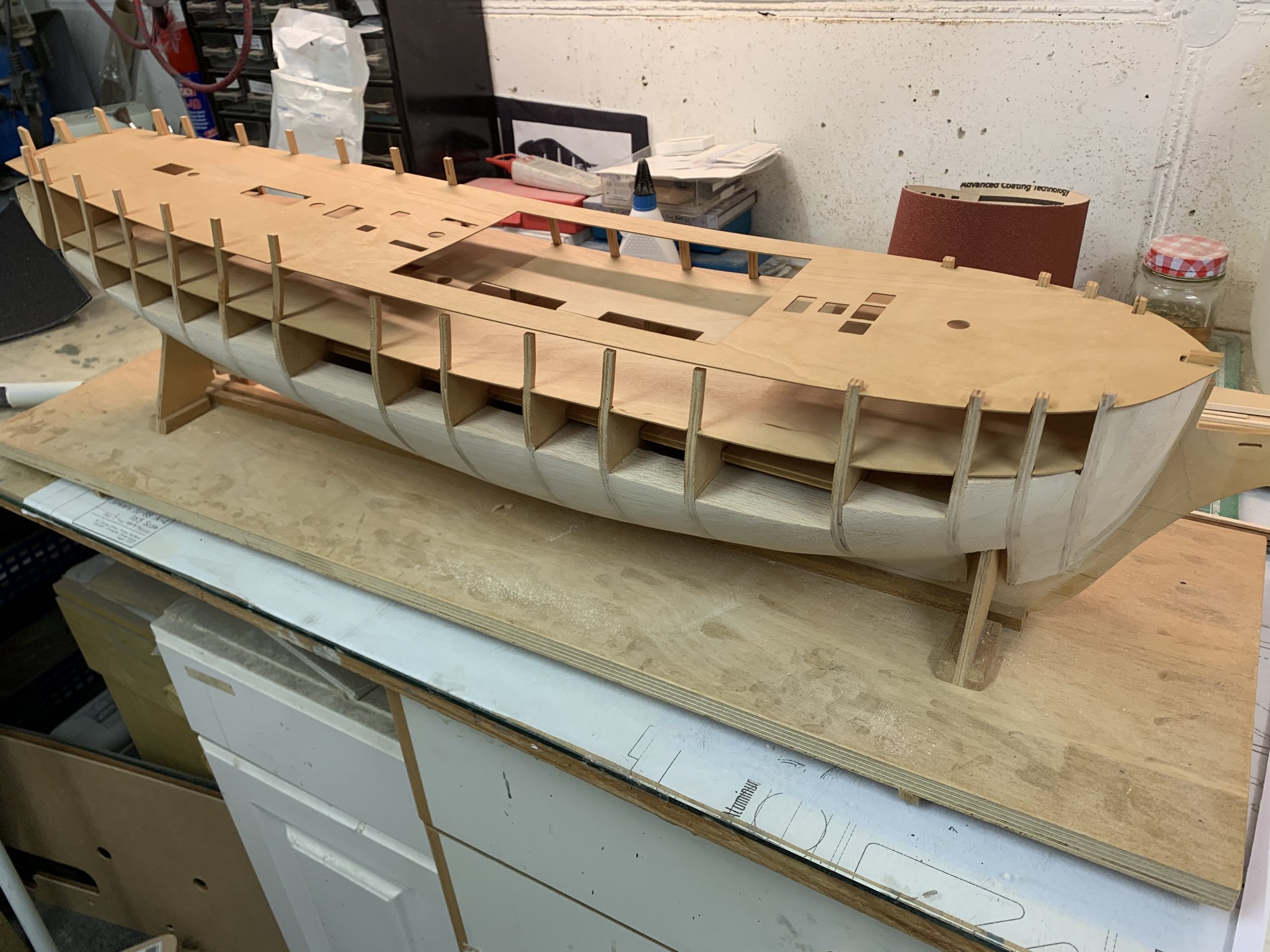
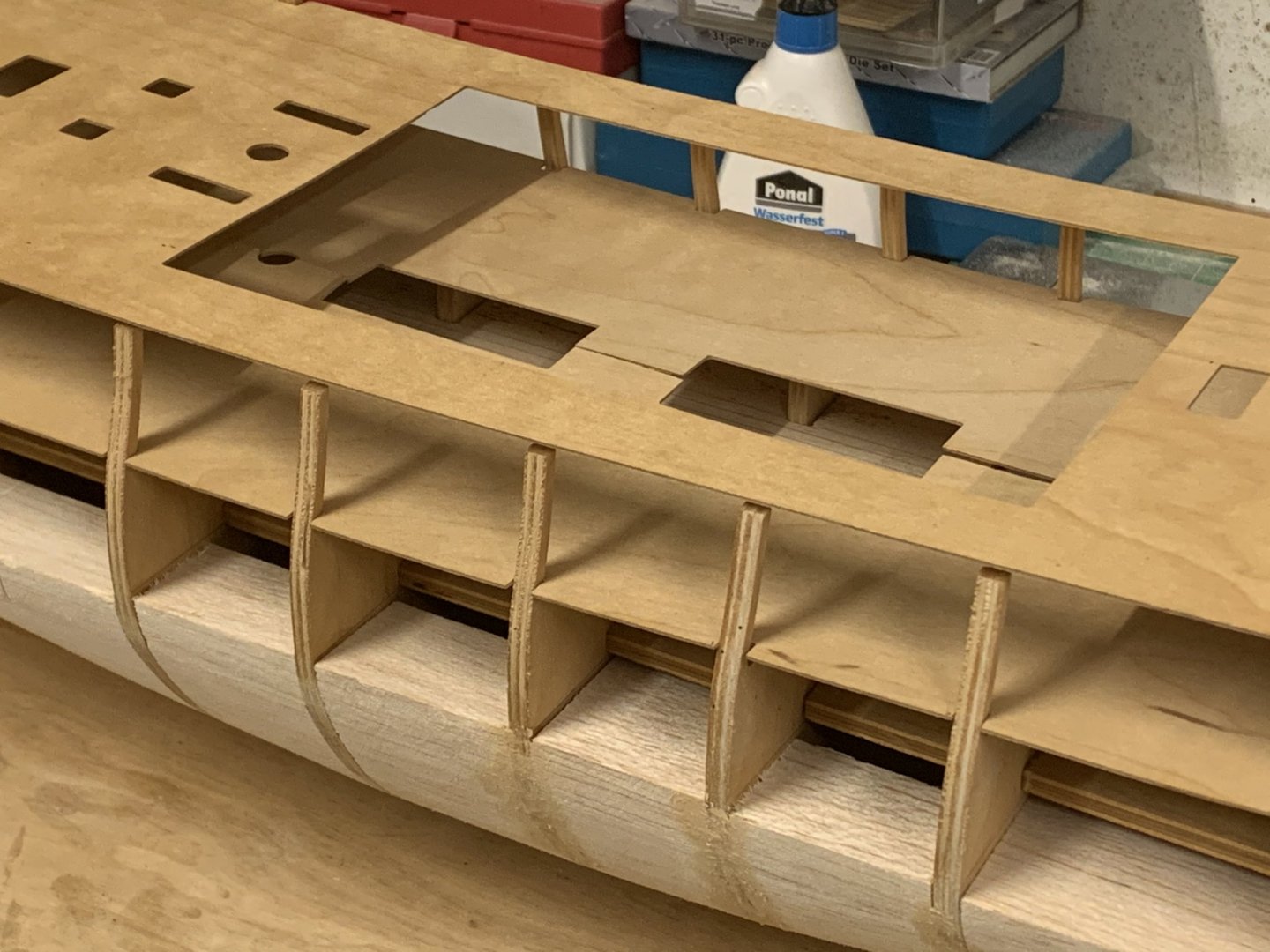
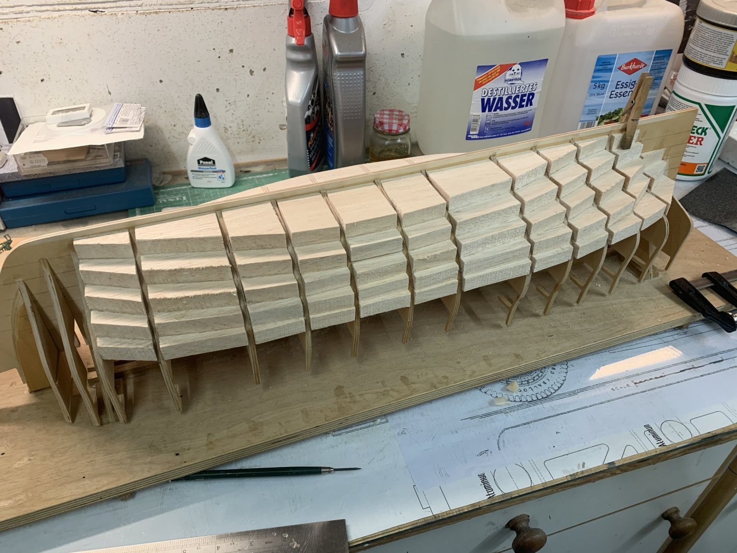
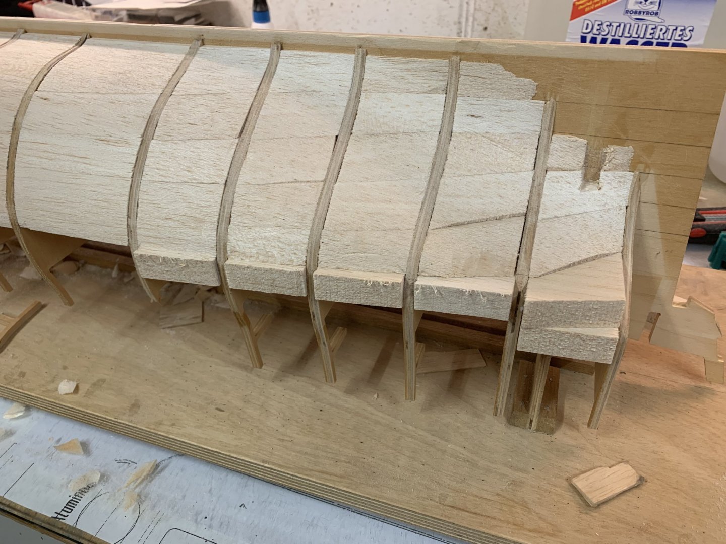
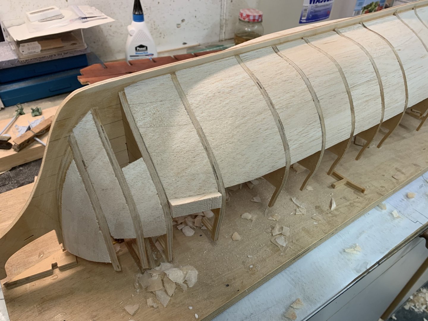
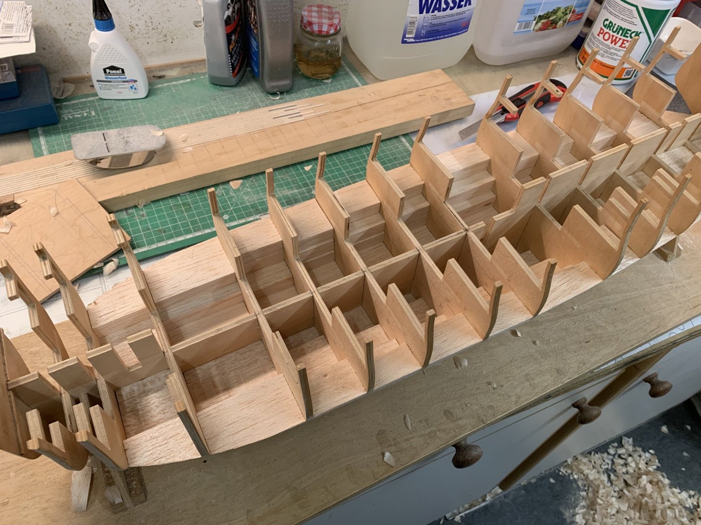
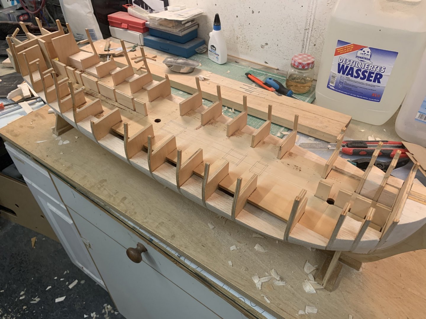
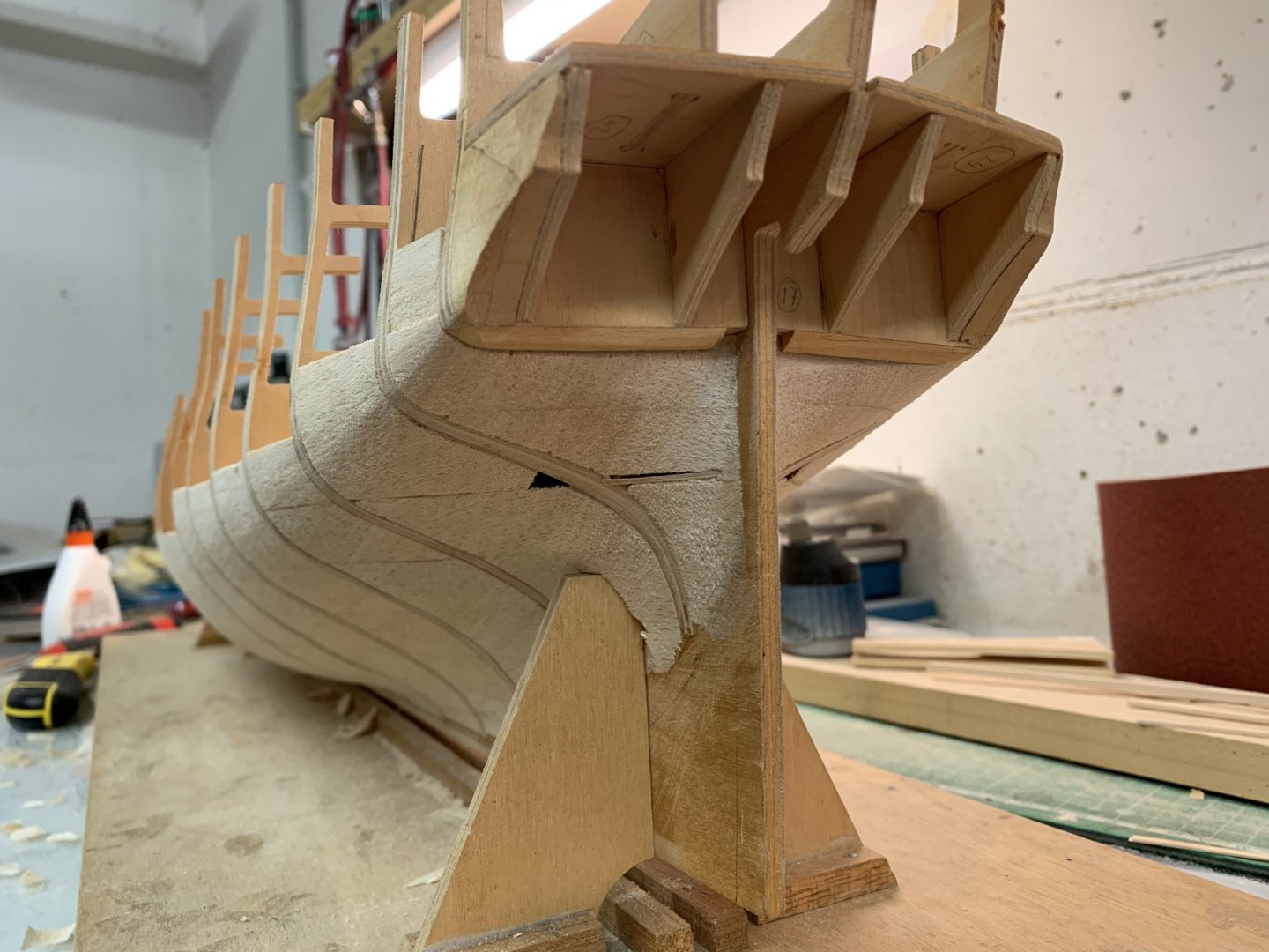
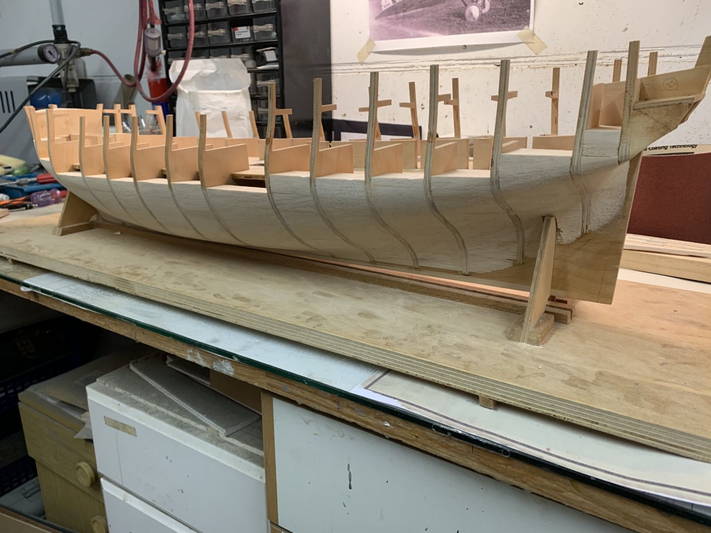
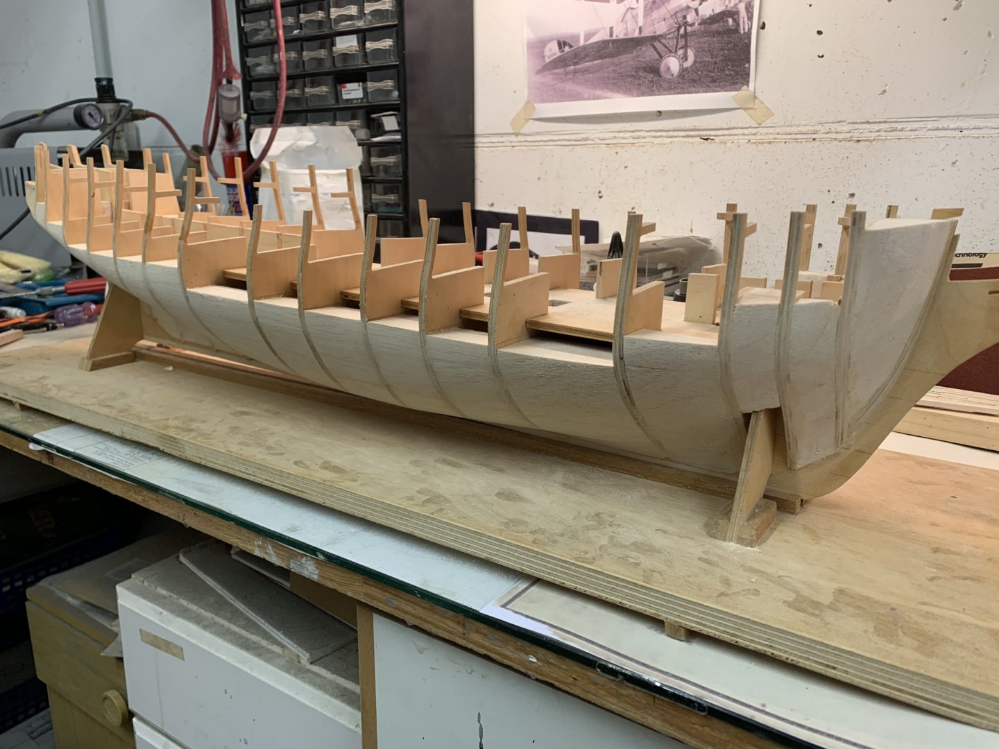
So after a break of close to five years, being inspired by Vanguard Models‘ Speedy (yes, I bought one), I decided to dust off the Diana and carry on where I left her. I had always had the intension of filling in the space between the bulkheads with balsa as, a) I didn‘t trust my planking skills and b) to check her hull after modifying the bulkheads the way I did. This was a slow process at first but started to move along once I got the hang of it. I found the best way to shape the infills was by carving... ...and sanding with 40 grit sandpaper on a small plank The bow and stern where also filled in The thick lower deck wasn‘t in place when I did all this so I could turn her upside down and work on her the ‚Hahn‘ way. This was nearly a disaster as it was very difficult to get it to fit right. In the end I also filled in the space between the very last bulkheads. The stern wasn‘t easy but manageable with a bit of planning and forethought. Some glamour shots at the end of the day that‘s all for now. Thanks for looking, Chris


-
Test post to show that I‘m working on my HMS Diana again, after five years! It‘s scary how time flies. I just want to check how uploading images from my phone works. A detailed update will follow over the weekend.

-
Yes. there were a few, so I decided to check them first, before the whole thing is glued up. I called the National Maritime Museum to order copies of their historic Diana plans, but they couldn't find them. The lady on the phone thinks they may have gone lost. I'll check again tomorrow or on Monday, see if they have turned up. But I didn't want to wait weeks before they do and my oder arrives here, so I decided to move on with what I've got. I went about it the same way as on the other bulkheads and found that the remaining five are closer to the plans than the others. Here they have been trimmed accordingly and, again, after bevelling, the test fit strips Looks like I may have trimmed off too much at the very bottom of bulkheads 8; 9 and 10. This will be corrected with the balsa infills later. A large box with several planks of 15mm balsa arrived at the office today. Excellent timing! Nothing beats a nice good night photo at the end of your successful building session --Chris