MORE HANDBOOKS ARE ON THEIR WAY! We will let you know when they get here.
×


CTDavies
-
Posts
73 -
Joined
-
Last visited
Content Type
Profiles
Forums
Gallery
Events
Everything posted by CTDavies
-
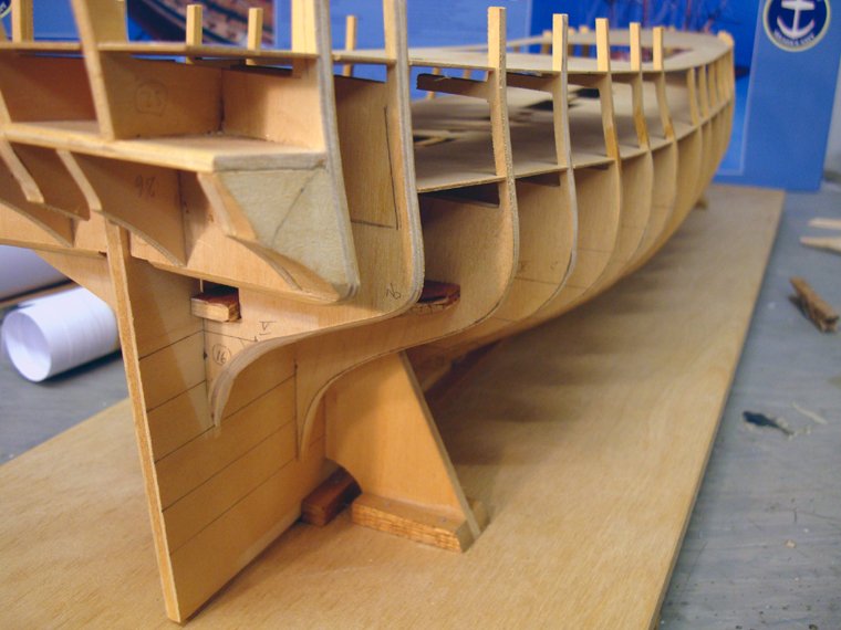
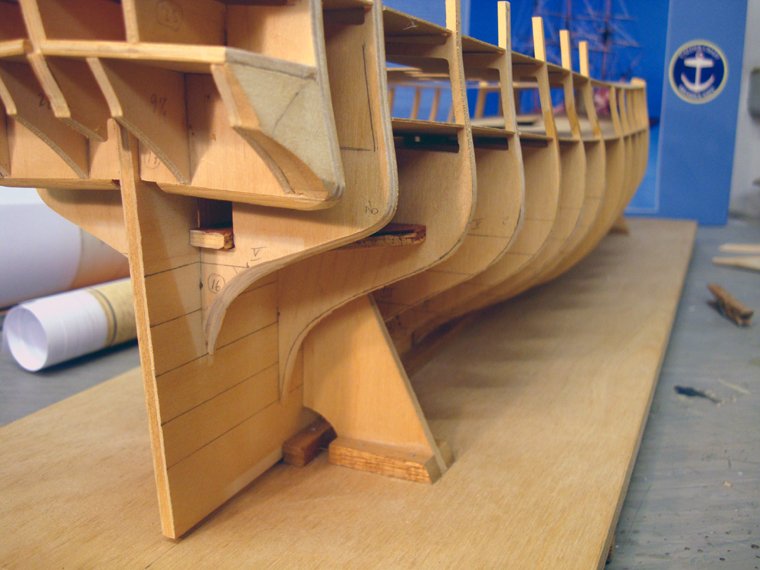
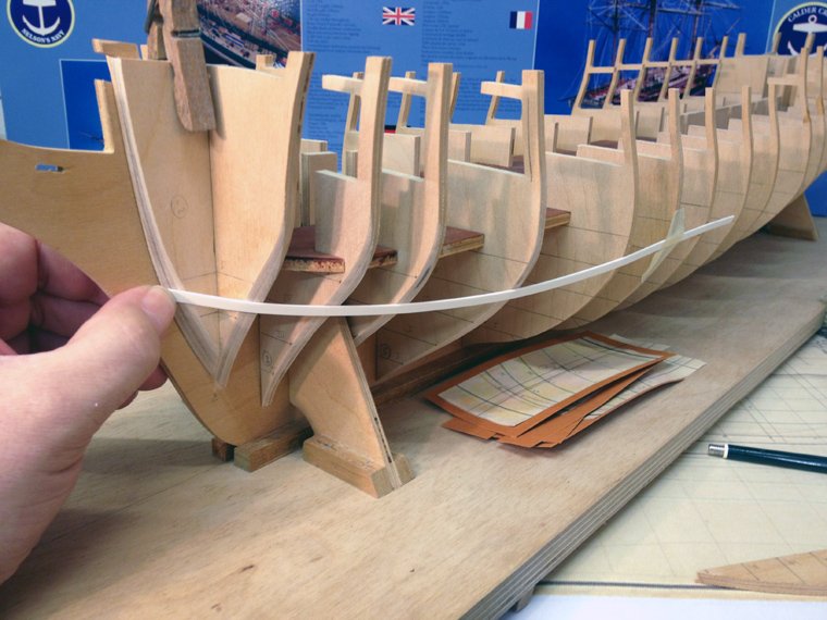
 So, the modified rear bulkheads have also been cleaned and bevelled. I have now completely reworked the rear six bulkheads (except #16 and not counting 17) and have carefully bevelled the front four. That leaves five in the middle. I'm thinking of ordering a set of Diana plans from the NMM so that I can check those remaining five as well. It seems wrong after going through so much work on these 11 and not do the same for the rest. So far everything has turned out quite well. --Chris
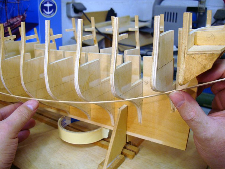
-
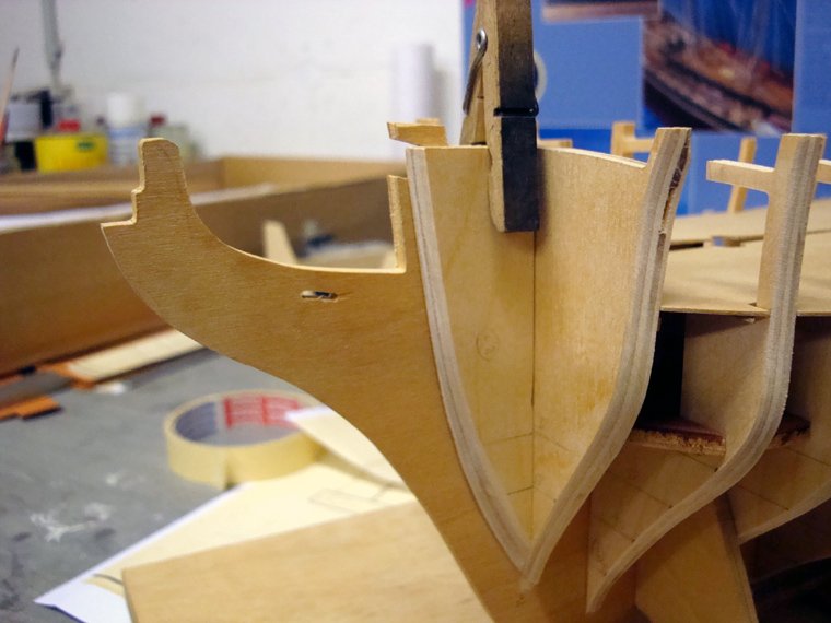
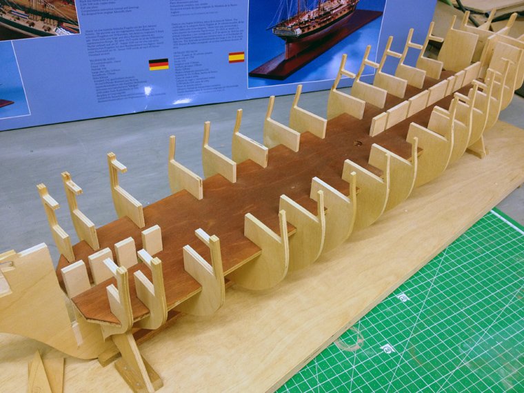
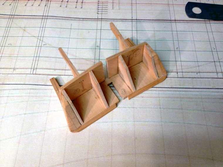
Well it's done now drove to my brother's house tonight (as we do every Sunday night, to have supper together with the whole family - a nice family tradition) My brother had balls enough to tackle the bulkheads with his bandsaw. I'll start cleaning up the cuts and the bevels tomorrow - it's too late here now. I like how they look, though. --Chris
-
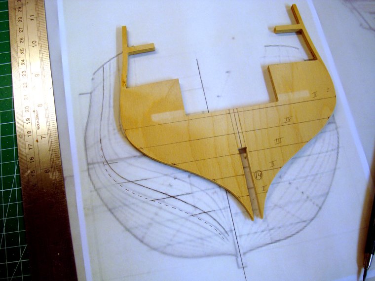
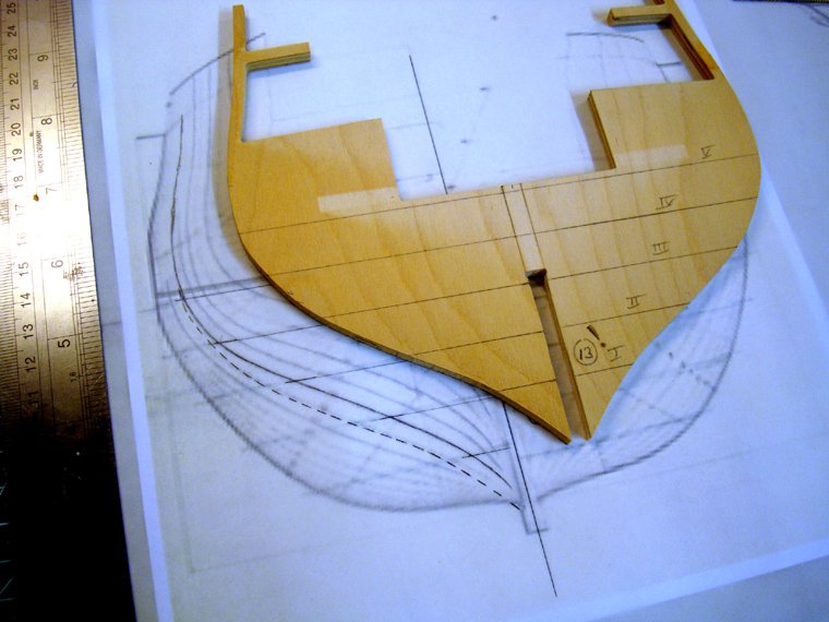
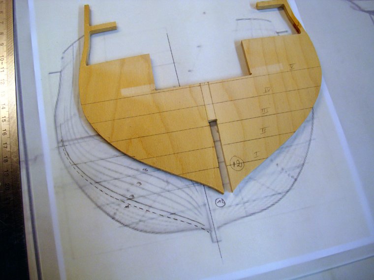
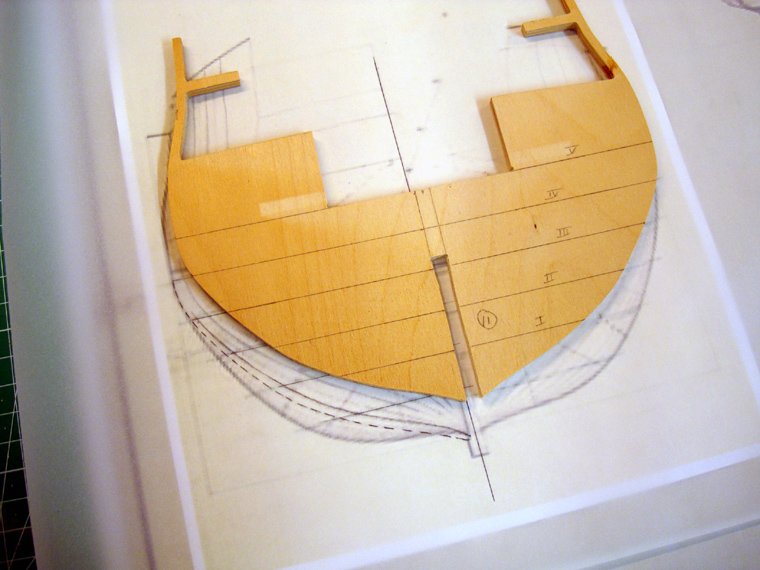
I'm pretty confident the bulkheads were aligned correctly when I compared them with the plans. The waterlines were the references I used for aligning. To put this more into perspective I drew on the bulkheads where the curvatures should be according to the plans. Bulkhead #14 would need to have the most shaved off. Looking forard to this evening, Bro' Let's see what we come up with
-
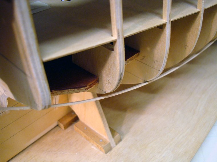
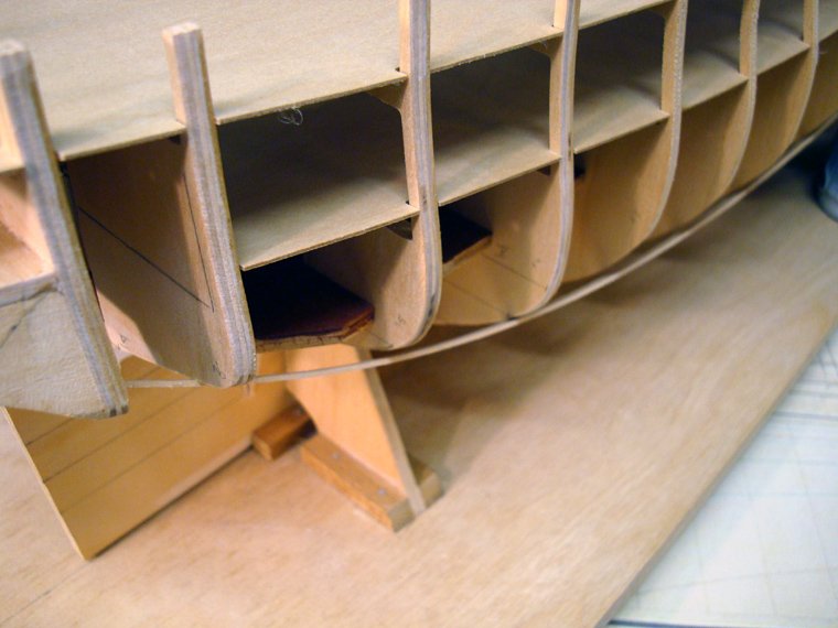
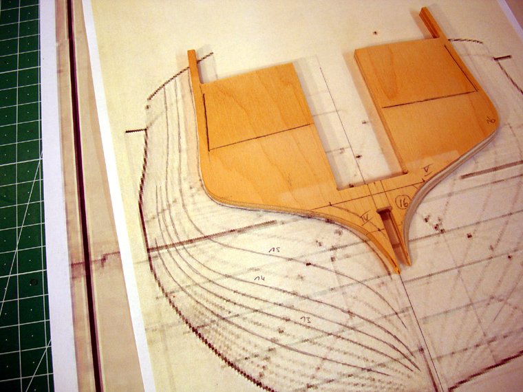
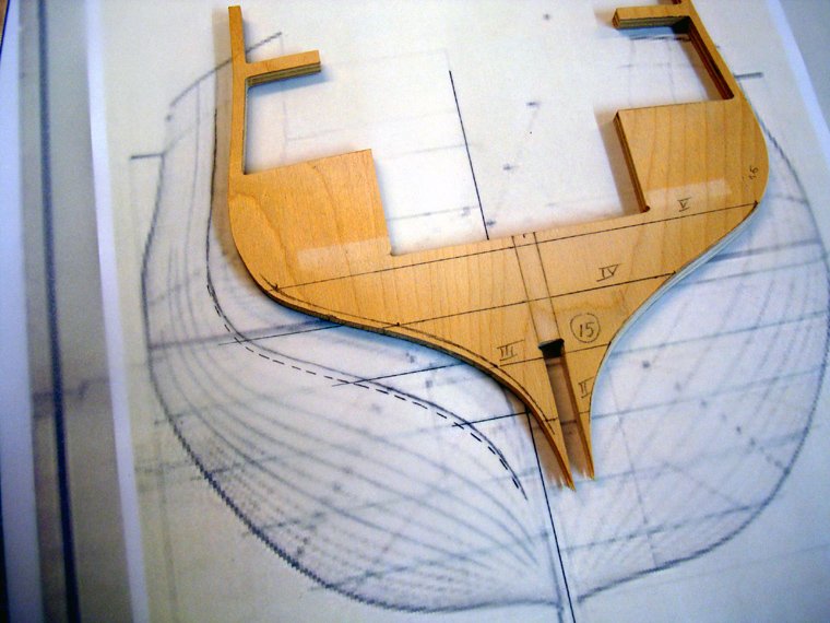
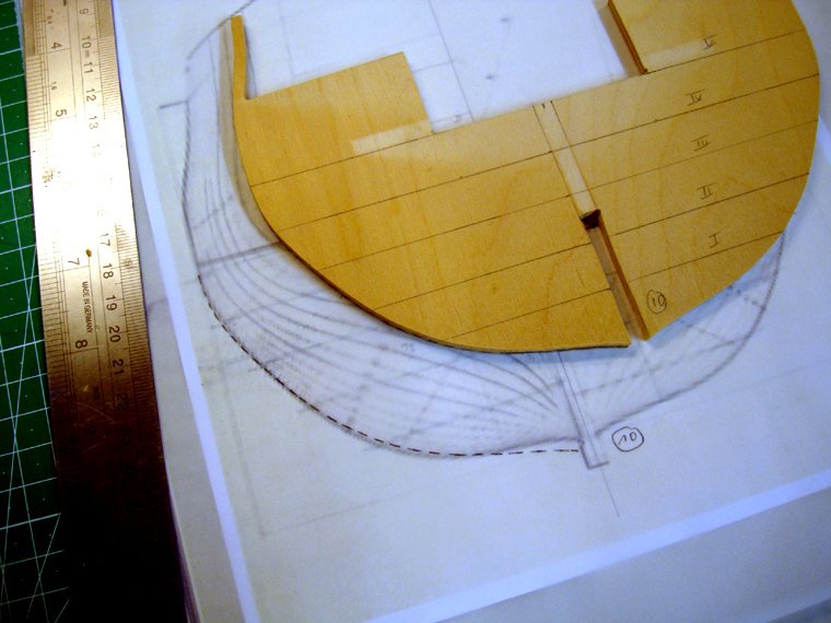
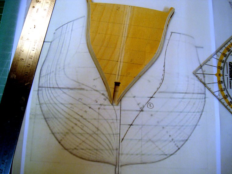
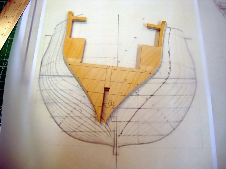
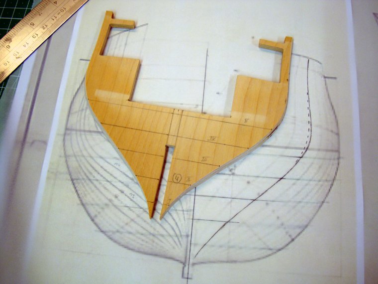
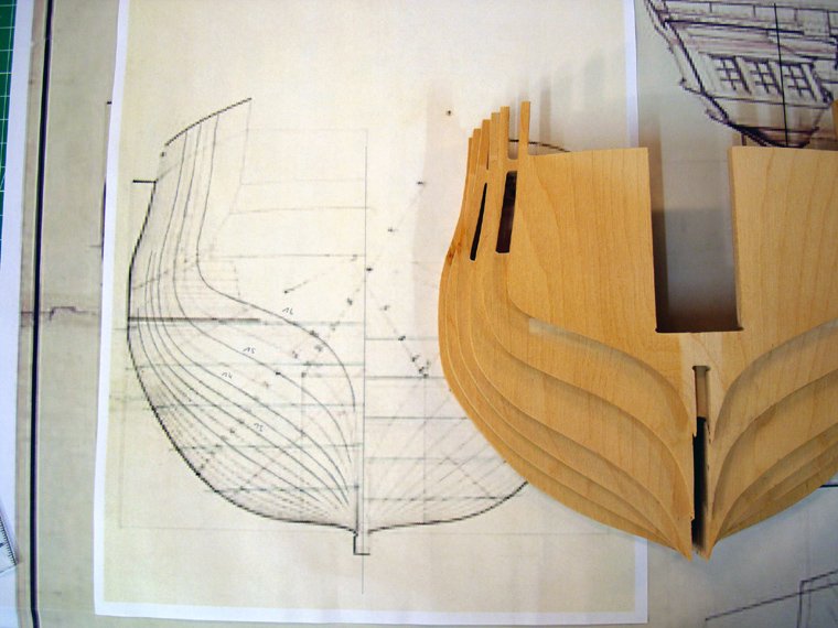
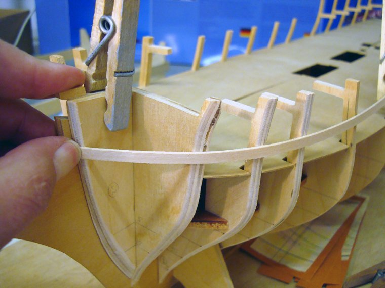
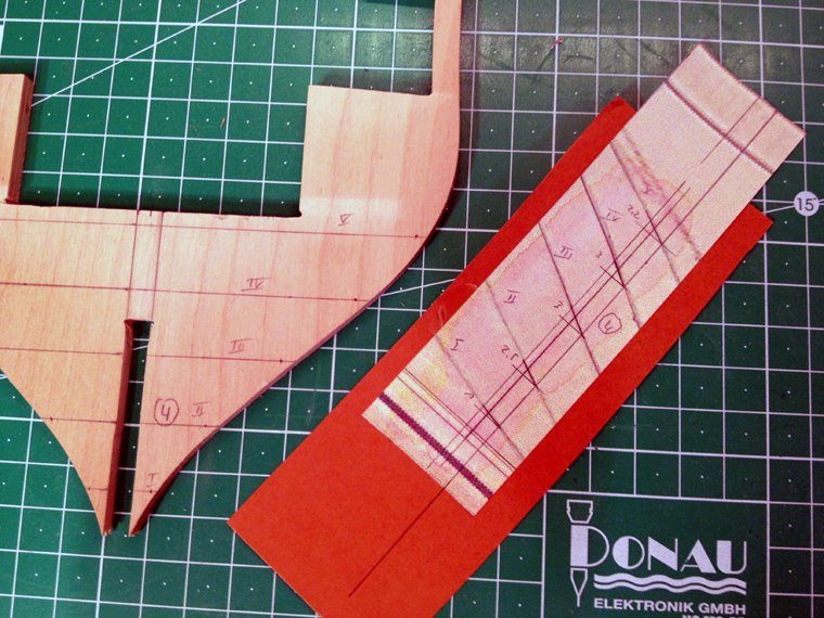
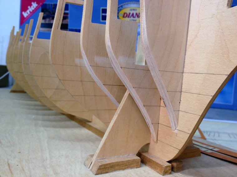
Well after being warned by both of you, I thought I'd give the stern a little more forethought than usual, before bevelling and I promptly ran into a dilemma. It was quite obvious when even looking at the bulkheads that something was not right. The test strips for planking I use as a guide for bevelling just didn't line up against the bulkheads very well at all. With the plans I had right-clicked from the internet I decided to check each bulkhead working from the back towards the front before I started sanding 16 looked ok...[ish]... while 15 would also have been passable, but from there it just went from bad to worse (the dotted line is the kits part), here's 15 14... 13... 12... 11... 10... this made me curious so I decided to check them from the bow as well 2... 3... 4... and 5 Conclusion: if the plans I am using here are really the Diana (and I believe they are, although I have no firm evidence), then the rear bulkheads are quite a bit out of shape. The front ones are very close to to my plans. Close enough to pass anyway. That is even apparent when looking at them stacked like here I don't have the AOTS here yet, as it hasn't arrived in the mail. I'm wondering if someone here could scan the drawing with the frames for me, so that I could check the bulkheads with it as an alternative source. I'm thinking of making scratch built formers for the stern here, just to see how they work out, before I start cutting around on the kit's parts --Chris
-
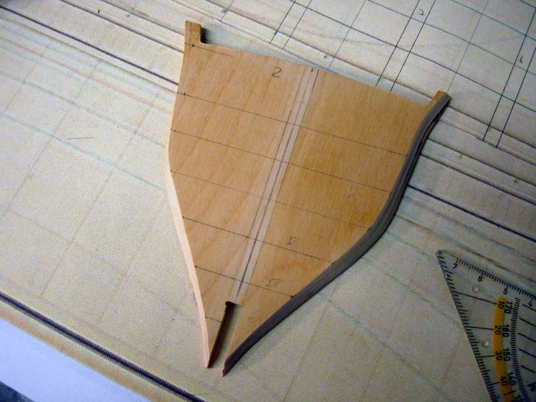
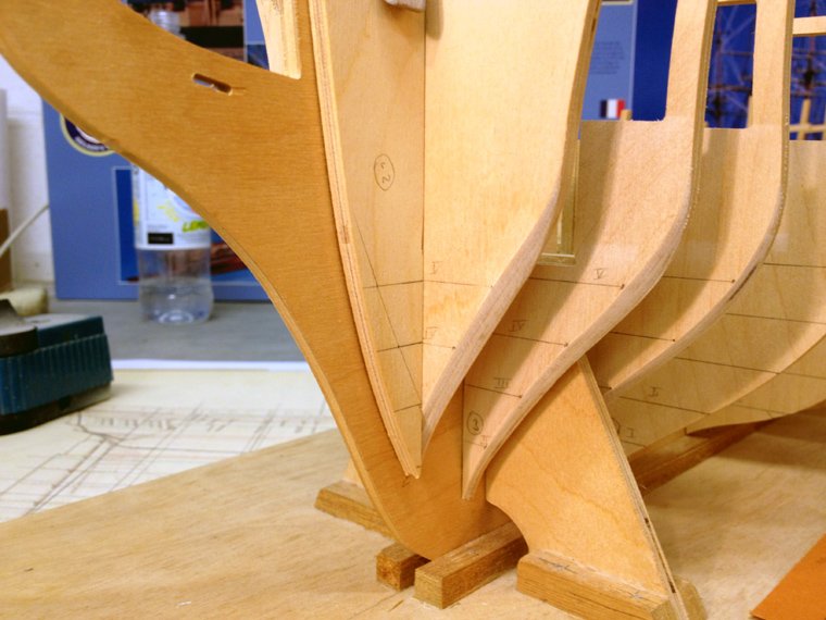
I did a bit more tonight. The plank termination templates needing some more sanding, as became evident when testing the plank strips on the bevelled bulkheads. The front edges are now quite pointy. Then I added some more waterlines to the front bulkhead to help transfer the bevelled edge over to the opposite side. The small pencil mark will act as a guide on how much material needs to be removed to make an exact copy of the bevelled side (hopefully) Both side of bulkhead 2 have been bevelled here and here all four front bulkheads have now been completely bevelled. I also tested strip planking here as well and still had to remove some material, before I was completely satisfied. I don't know how many times I took the whole thing apart and built it all back together again to check how the planking will fit. So the first part of step one of the instructions has now been completed. Next I'll tackle the rear four bulkheads. There are some really steep angles on those bevels there! I'd hate to have to do this on a glued up frame with everything else in the way. Damage would be inevitable. --Chris

-
Looks like it's an incredible kit. Also, the instructions look amazing. Nice build, of course --Chris
- 117 replies
-
- 2
-

-
- victory
- billing boats
- (and 1 more)
-
Hi Ray, you are of course absolutely right about the upper parts of the bulkheads. I wasn't really sure when and how to tackle these but tonight I thought I'd just go for it. The waterlines on the plans I found only go up as high as -well- the waterline. Initially I thought I'd wait until the AOAS arrives, hoping there might be some further drawings there I could use to make some more templates, but I gave some careful eyeballing a try this evening, with quite pleasing results. It probably took the best of two hours to do one side (pt) of bulkheads 2; 3 and 4 but by working very carefully and double checking and checking things again it all went well. The distance between the waterlines on my plans is close to 15mm, so I'll be ordering some 15mm balsa to fill in the space between the bulkheads as Ray recommended. Not that it's necessary to stick to the waterlines with the balsa infills, I'm just hoping that it might work out to be a bit cleaner that way and therefore maybe easier. Note how there's a gap in the plywood of bulkhead 2. I also dug out my old camera tonight as I wasn't too pleased with the quality of the images my i-phone took. This one looks a little bit better. Thanks for stopping by, and thanks to the mods for fixing my title again (1:64th scale), --Chris
-
Thanks for fixing that ccoyle (now if you could also fix 1:64 - thanks again) I did a lot of flying scale stuff back in the noughties, but was too afraid to fly, so I eventually gave up. This is my first wooden ship build, --Chris
-
Hi Chris, I'm also a Chris, and was also diagnosed with a partial colour blindness which put and end to my ambitions to become an RAF pilot. Ended up in architecure. Can't wait to see pictures of your Victory (I actually saw -and walked on- the real thing just after christmas) --Chris
- 117 replies
-
- 2
-
-
- victory
- billing boats
- (and 1 more)
-
Disclaimer (I wonder if this is necessary) The drawings I printed out from the internet here are strictly for my own use on the model here. No copyright violation is intended. When I am finished using these drawings for this model they will be destroyed. No copies will be made. Now I've seen I've forgotten to include my name in the title here. How do I work that out? --Chris
-
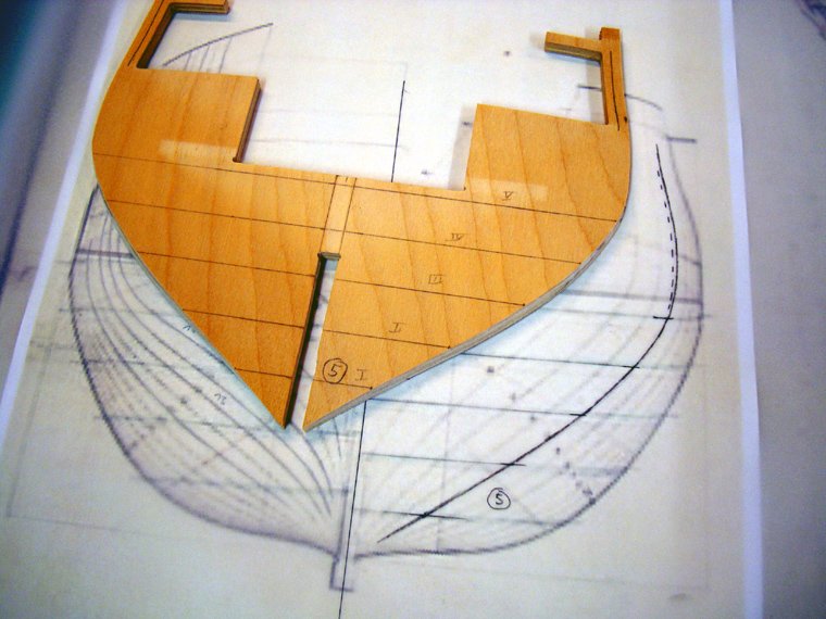
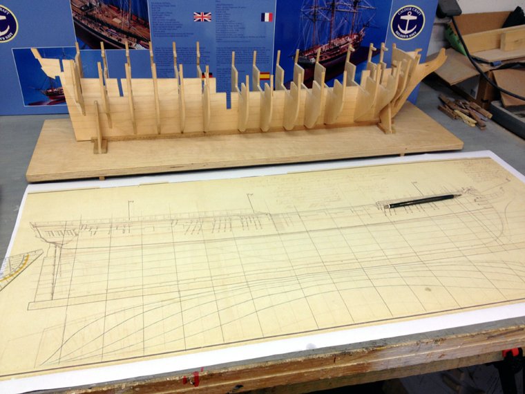
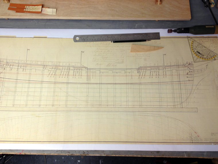
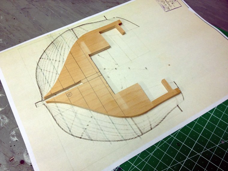
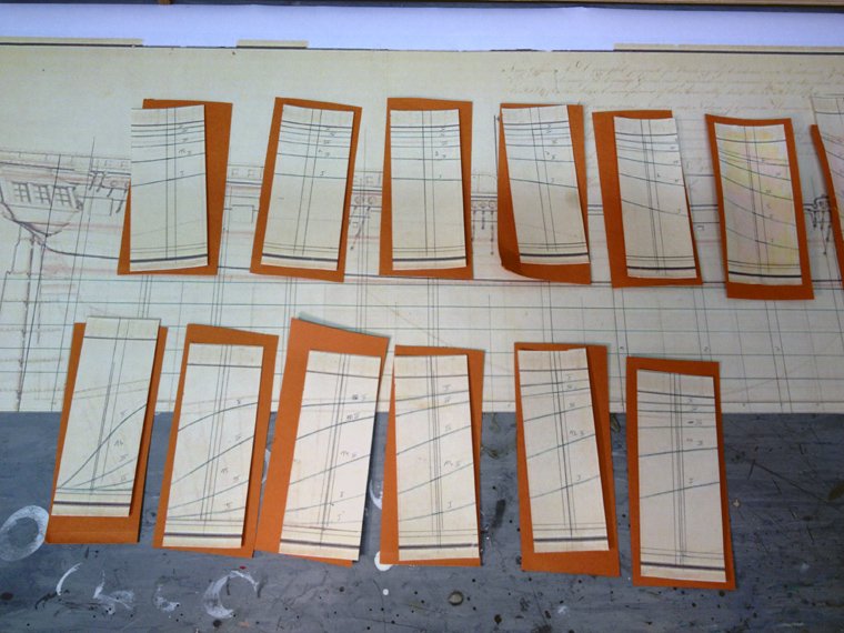
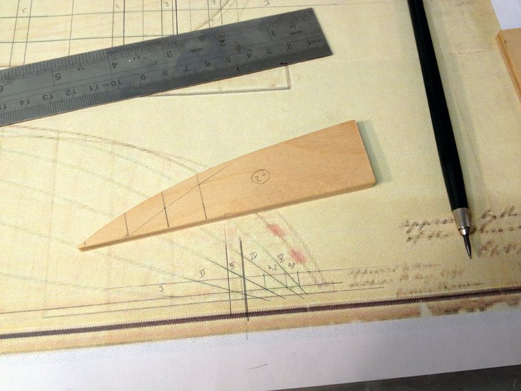
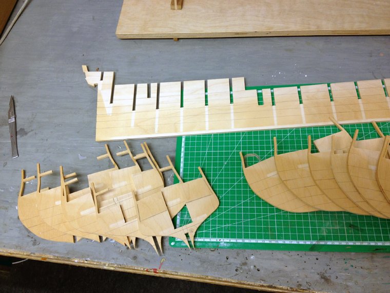
I googled around a bit and found a low res side elevation which I was able to print out in the correct scale (which made it even more low res). Then I drew out all bulkhead positions on the elevation and lines plan. I'll explain why later. The bulkheads match the frames on the body plan quite nicely The water lines were then drawn onto the keel and all bulkheads I made templates for each bulkhead from the lines plan showing the angles water lines. With these angles I could approximately measure out how much needed to be sanded off the bulkheads for the bevels. I'm following the recommendations in the instructions here that the front four and rear four bulkheads should be bevelled before they are glued to the keel. Now you can see why I copied everything onto the drawing I found on the internet. First bit of bevelling done (phew!) The nice thing about these templates is they can be used to check the angle of the bevels. I watched my brother do this on his dutch Zweidecker more done The plank termination template wasn't so easy. I was able to draw out some basic geometry using the lines plan which was then drawn onto the part quick check in situ and after about half an hour of careful sanding I used a piece of plastic card to check that the bevels run true. So far I am very satisfied. The front four bulkheads are all done. For my next update I'll do the rear four. --Chris


-
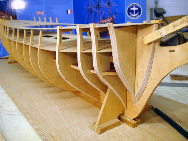
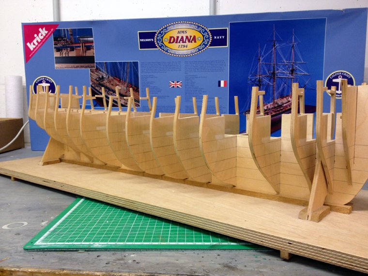
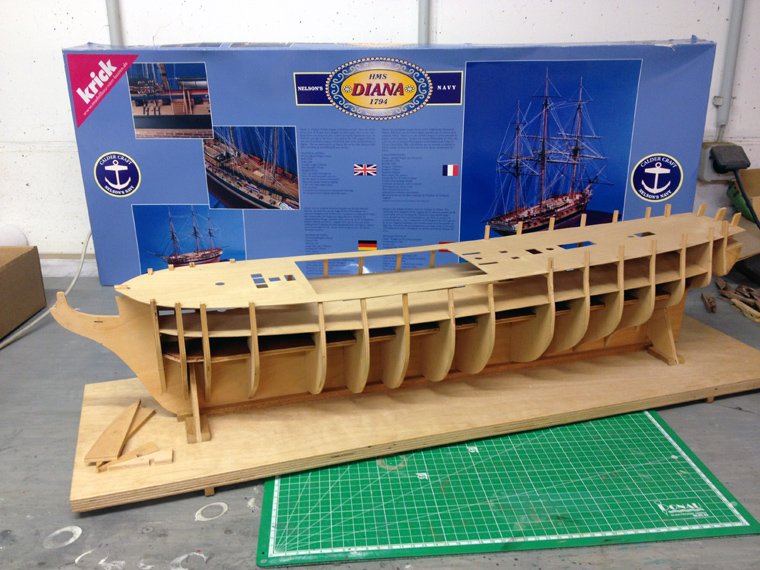
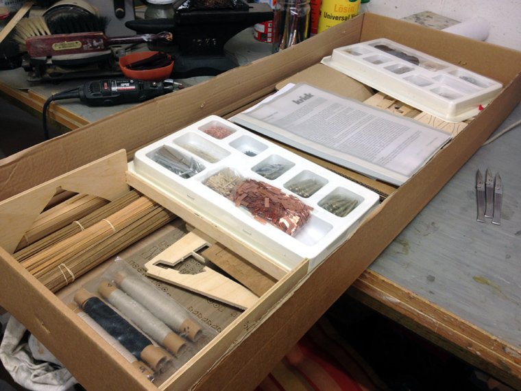
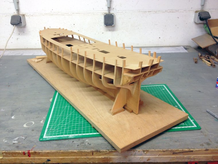
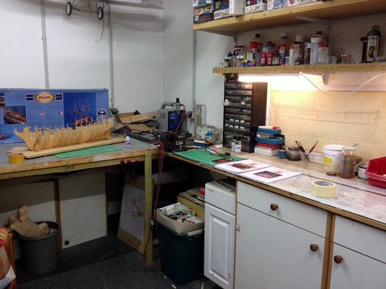
Hello All, after looking around for a while for a nice model ship project, I was able to buy a started Calder Craft HMS Diana in good condition at a reasonable price. I have been thinking of building a ship model for a little while now, and even started designing a few projects for a scratch build, but in the end I decided I needed to get a good quality kit as a first build. The Diana was on the top of my list because a) it's Royal Navy (British ships interest me most) and it's a late frigate, a type I find very attractive. So it was pure luck that one popped up on Ebay which turned out to be within driving distance so on a nice Saturday morning I made the trip and bought it on the spot. Here she is. The building board was already built by the PO (previous owner). Nothing has been glued yet. The box top is different than the ones being built here on the forum. Maybe this is an early version kit or one specifically for the european market? The lower deck had already been painted by the PO. I won't worry about this as I want to plank the deck anyway and maybe add some details This is what's in the box The stern section was also already built. All to a good standard. And here another view. I have already ordered the AOAS on the diana and hope it arrives soon as I intend to dress out the lower deck a bit, even if it's hardly noticable later. This is my hobby cellar, all cleaned up (happens very rarely!) for the new build So, this is my first wooden ship build, so please be patient with me. I have always been a slow builder so this might take a few years - haha. Feel free to tune in, next I'll show you the beginnings of part one: Hull construction. --Chris
-
I have a question here about the NMM's Bellona plans that I imported into my CAD programme for an off and on project. On the side elevation I noticed the frames stations are tilted very slightly to the rear. I have the elevation placed in my CAD programme with the water lines absolutely horizontal, which makes sense to me. The scale bar under the keel rises towards the bow which also looks right. So I was wondering if the rear tilted frames might be due to the photographic process in the museum or even scanning them here afterwards (or a combination of both). This is an amazing thread and one of my favorites on MSW. I come back here frequently to see Marks progress and follow the discussions. Chris
-
Question here for Chris Watton. This was originally posted at AEW's Vanguard build but he recommended asking Chris here as well. The Vanguard being an Arrogant-Class design is very similar to the Bellona-Class, if not even a direct copy. Would it be possible to convert the Vanguard kit to a Bellona-Class design? I know there are differences in the decorations, but I'm hoping the rest may be pretty much the same. I think I read somewhere that there were a few changes around the bow only, but I could be wrong. If Chris could enlighten me, that would be very nice. I would also like to say that this thread is the one I check out most frequently, to see Chris' progress on his Victory and to find news on a pending Victory Models Bellona kit. That Bellona in the picture on the first post here of Chris' Bellona is one of the most beautiful models I have ever seen. Chris (another one)
-
Now it's where it should be. Thanks for stopping by. Please provide as much input as you can. So far this has been quite enjoyable, but as I've said, I have a lot to learn. Next I want to work on McKay's Body Plan. Maybe with some help from Avery I can draft my own frames. We'll see. --chris
-
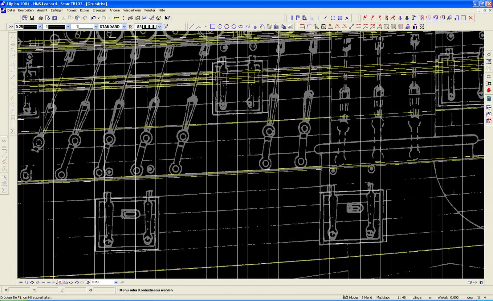
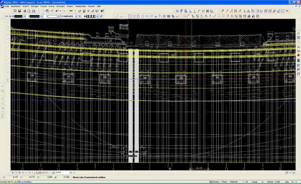
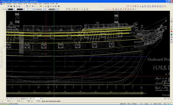
The top centre gun port here is not located exactly between the two single thickness frames here (you have to look closely and you'll see what I mean). I changed its position. Actually I went through all gun ports and moved them around just a tad to put them right where I think they need to be. This was the first deviation from McKay's Profile. Would you have done the same? I'm assuming this is a typical inaccuracy you would find on ink drawings.
-
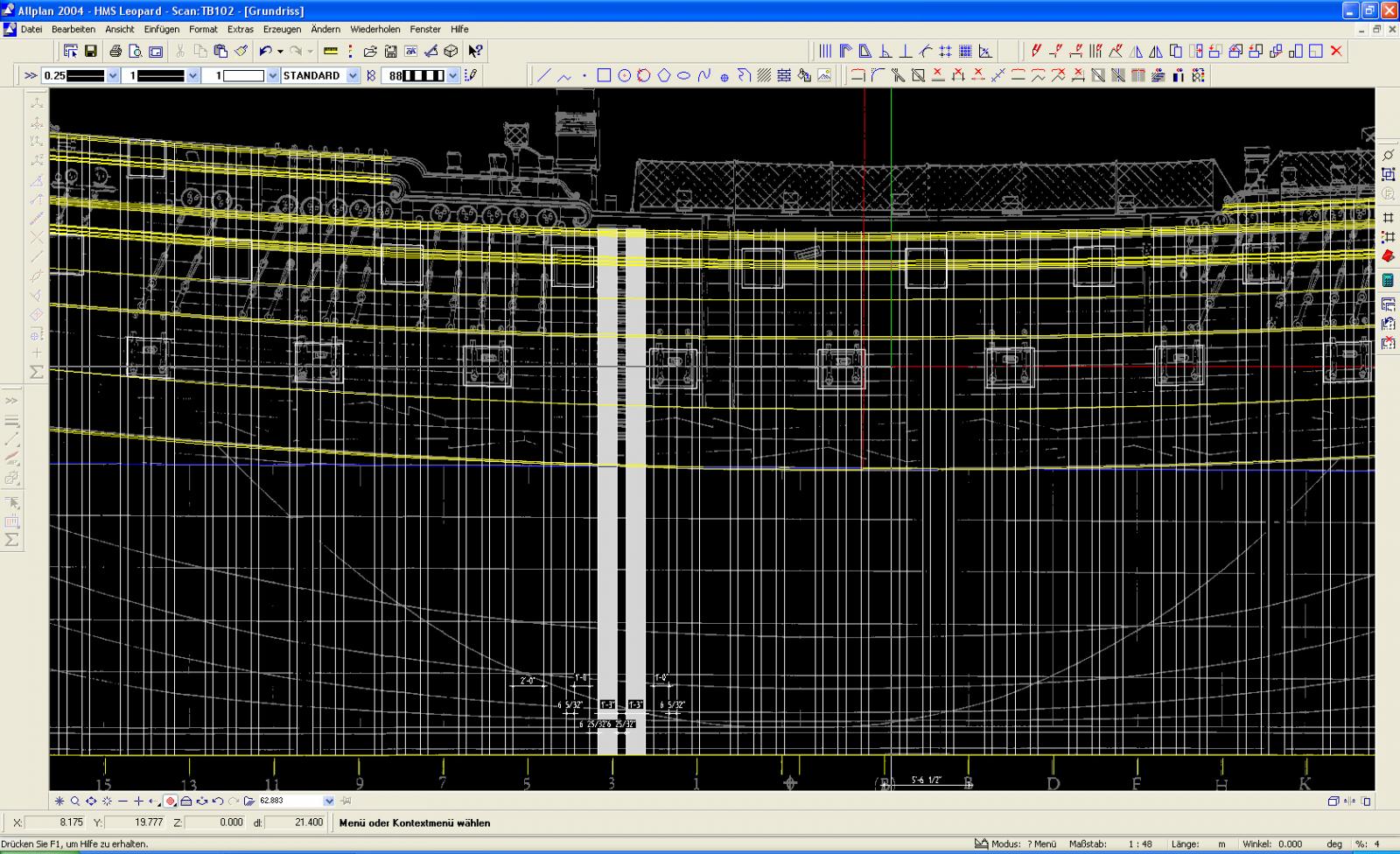
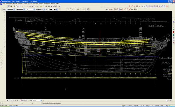
I promise that by the weekend I will have worked out how to embed images. This is where I'm at now. You can see the wales, the rails and the frames, done the Hahn's way.
-
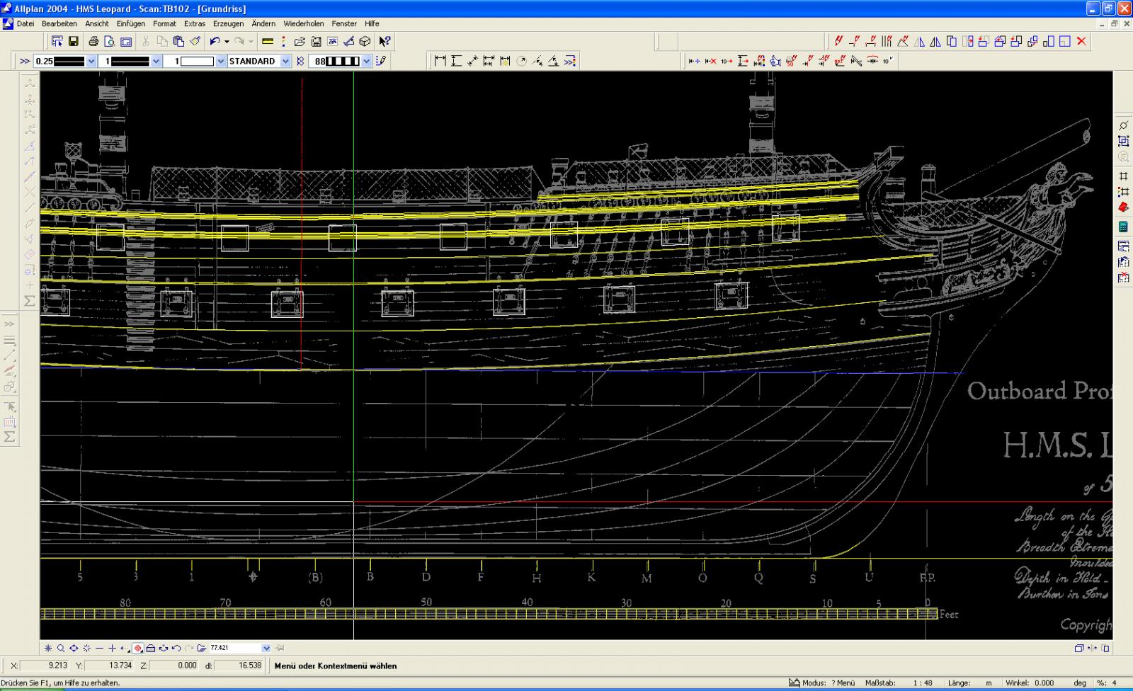
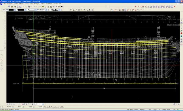
There was a slight difference of frame thicknesses about where the steps are on the hull, just aft of the dead flat. I solved this my own way by omitting the double thickness frames here next to the gun ports and increasing the single frames to 1' 3". This turned out to be a very tidy solution and I was very pleased about that. I have not made a decision yet on what scale my project will eventually be. At the moment I am designing my Leopard full size, which is one of the advantages using CAD programmes. I did print out a side view, sorry, the Outboard Profile in 1/36th and 1/48th scale, but, boy, those scales would make a BIG model. For now I'm comfortable working full size.
-
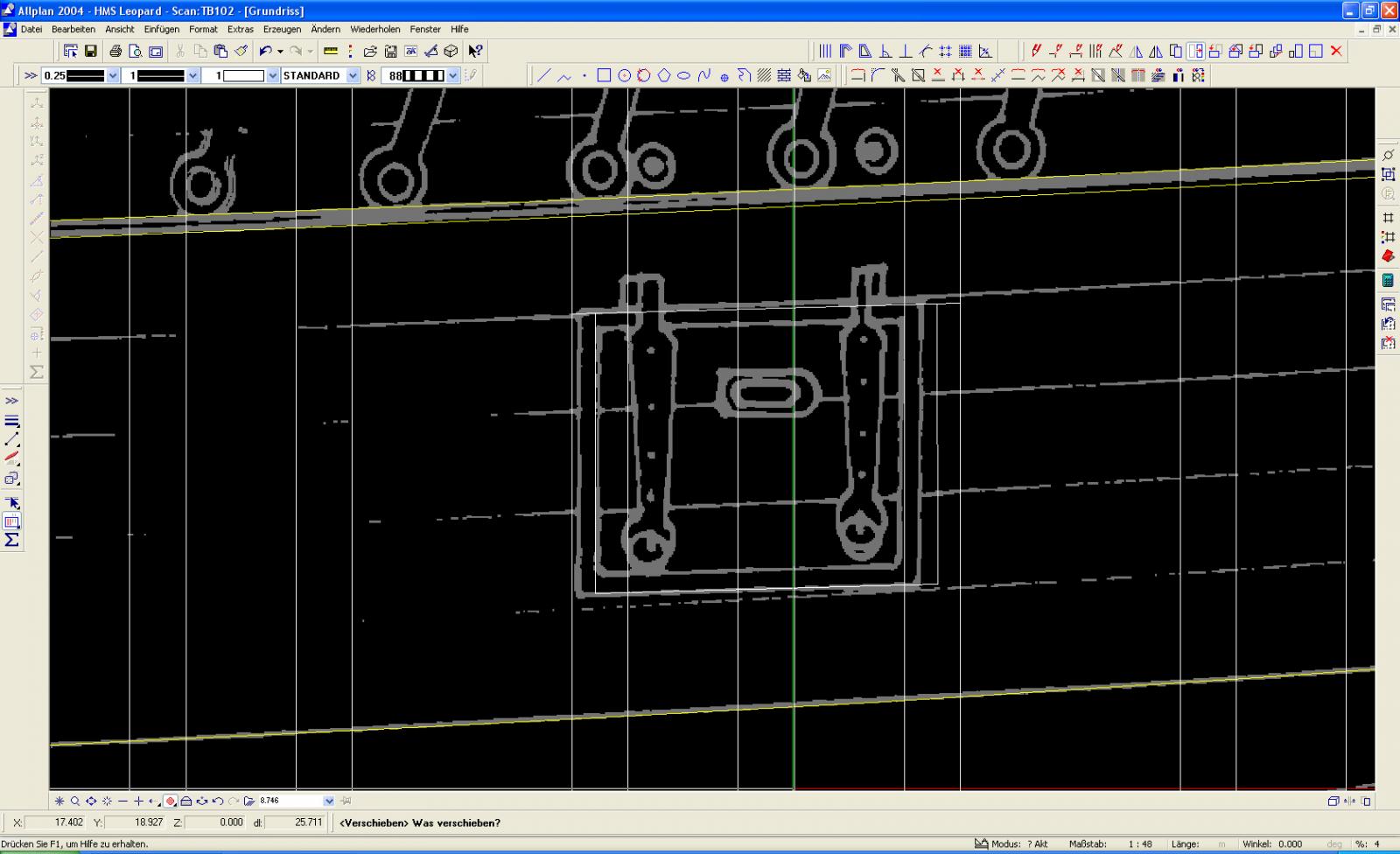
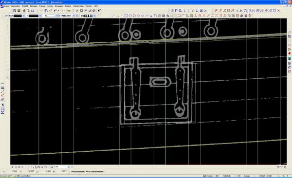
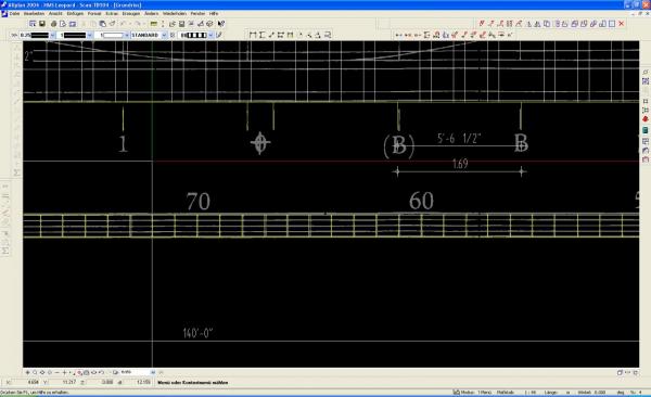
Hi Wacko, thanks for tuning in. The next shot is a close up. According to my CAD programme the distance between the Room and Space indicators (as I call them) is exactly 5' 6-1/2". Could that be right? I have basically no idea on sailing ship designs so I'm going to have to rely a lot on your generous help here. Of course I could try and locate some of those historic books on ship designs and dive into them for a year before I start on this, but that wouldn't be much fun, would it? I do have Avery's double set on Ships of the Line and the first volume has a lot on designing, so I'll be reading that one a lot in the next few weeks. Here's that close up:
-
I am a big fan of Harold M Hahn's Ships of the American Revolution and decided, to keep this design fairly straightforward, to adopt his way of framing using his double and single thickness method as used on his HMS Alfred design. While working on this I found, to my genuine surprise that this corresponds with the short vertical lines under the keel that are obviously Room and Space indicators. Some gun ports had to be shifted slightly.
-
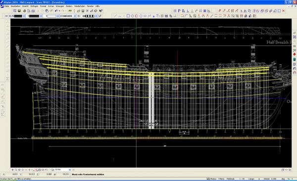
I'm going to have to work out how to embed images into the text. Bear with me, I'll get there eventually. Next thing I noticed was the wales, strakes and rails aren't always parallel. Aftwards of the dead flat they are, but towards the bow they run closer to each other. At first I thought this might be a scanning inaccuracy but McKay's Profile is cearly the same and several of the models in Winfield's book also have this feature. Again I decided to stick to McKay's Profile.
-
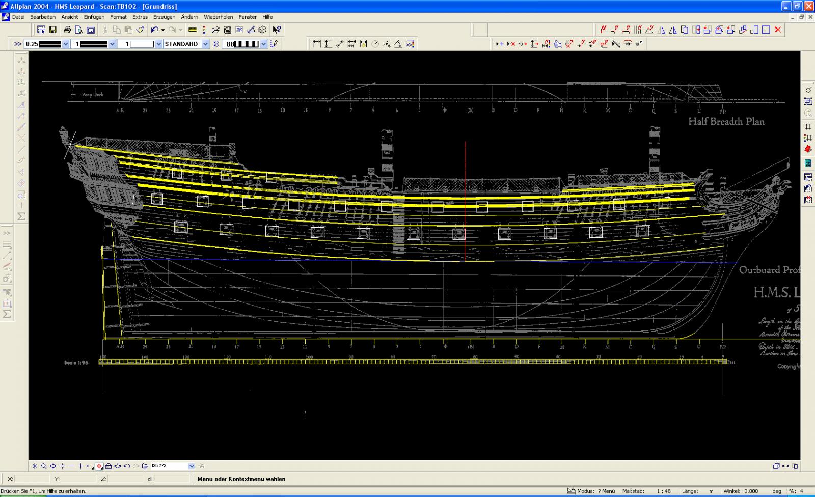
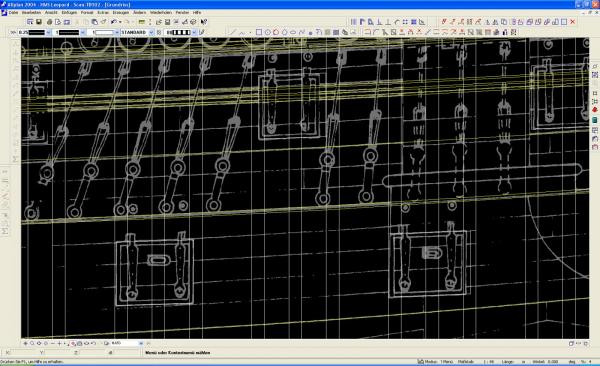
Ok, at first I was hoping to take part on the group build HMS Triton, but as my intention was to copy the complete design into my computer to make my own CNC cut parts, I was turned down by the admins due to copyright concerns. As an ex kit manufacturer myself I fully understand their views, although I think that home designed CAD kits/models are a way of the future that will soon take up a much bigger part in the modelling world. After that failed attempt, I tossed around a few ideas for a while and stumbled over Rif Winfield's The 50-Gun Ship on that famous internet auction house, which was quickly purchased. The 74 is the secret love of my life especially the Bellona, but as a first ship building project I thought I might be biting off more than I can chew with something of that complexity. I have been building models all my life, mainly airplanes with a lot of plastic and a nice number of scratch built flying scale models and a few cars, but now, It's time for something new - a sailing ship. Winfield's book has some very nicely done drawings, what the aircraft guys would call three views, done by a Mr. John McKay in 1997. I scanned part of them and imported them into my CAD programme (for my own use!). As an architect I use one of the most popular german CAD programmes at work, designed especially for architecture called Nemetschek, which is what I will use for my Leopard project. The eagle eyes here will notice that I'm using the dated 2004 version as that's the one I've got. I'm calling this a project as I don't know if I'll ever finish it, so please consider this more an ongoing learning process than a build log. I started off with the Outboard Profile. It was scaled up to full size in the CAD programme and the whales were traced on a new layer by using circular segments and here the first problems popped up. From an engineers standpoint, I was expecting the whales to be of a full circular segment but they turned consist of several, at least two, each with a different radius. For now I decided to stick to McKays profile.
-
Hi All, newbie here, Chris from Germany. I'm thinking about starting a 1:36th scale HMS Triton and have looked at the first keel drawing and have started some minor CAD work, but first a bit about myself. I have been building models all my life now but mainly aircraft and for the past several years flying scale WW1 aircraft. I designed my own, and for a short while had a company that sold my designs, but this was stopped when real work got in the way and time became an issue. For about the last two years I have not built any models at all (apart from playing around with a Pocher Mercedes) but have started restoring an E-Type Jaguar instead (I have recently become somewhat of a car nut). Work on the Jag can become frustrating at times because I can't do very much myself due to lack of experience and equipment. When a friend asked me recently how I actually restore it I answered 'I drive parts around in the back of my car'. Let's see if I can install some pictures here: this is an early version B-17 I designed and built around 2007 here's an SE-5a that a customer built and here's a Sopwith Snipe that another customaer built This is my 'other hobby'. A 1969 Jaguar E-Type, currently undergoing complete restoration So, I've been thinking of building a model ship. My brother, known here as Mr. Hollom, has been doing that for many years now, and I occasionally borrow books to read or just look at and enjoy the models shown there. Over the last few months I have become quite fond of the HMS Bellona, but I'm afrraid a scratch built 74 might be a bit too big for a first project. Then I was looking around for a suitable kit, and for a while thought of doing Calder Craft's HMS Diana, when I discovered this forum. The idea of building a frigate is attractive, as I think it can be handled by a first time ship builder. I've started in my own usual way: the pdf was converted into an image jpeg using my Acrobat Reader and this was then imported into my CAD programme and scaled up by 1.333 to reach 1:36th scale. Being an Architect by profession I use an architects CAD programme, which works well for what I need it for, but it's not really possible to build a 3d model of a sailing ship with it. What I can do is draw out parts 2d like on a drawing board back in the old days. I'm hoping that building in a larger scale might have its advantages over a smaller one when it gets to the details and maybe rigging later on. So eventually I started tracing the keel drawing in a new layer. I read in some of the other posts that showing images which contain parts of the copyrighted drawings should be avoided due to copyright restrictions, so I'll try to follow that. I really hope that copying this design into my CAD programme for my own private use does not infringe any copyright laws also. If so, please let me know. I do not intend to make any parts available later on and I will certainly not give away any file etc for kit production or similar. Redrawing the pdf is a somewhat low tech way of creating a digital version as I simply try to hit the existing lines right in the middle when redrawing them. Working with dwg or similar would be much more exacting but I don't even want to ask for them. The keel was then broken down into its individual parts and these were laid out as on a 100*30cm plank of wood. From my WW1 modelling days I still own a CNC milling machine which a I want to use here to cut out parts. I'm not even sure if it still works, as it has been stored in my basement for a few years now and it needs to be cleaned and the computer set up again. Also I don't know how it will work on thick hardwood sheets. It could easily work its way through 6mm birch ply which was frequently used on my flying scale planes, so I'm hoping it will be fine using a 1.5mm or larger milling bit. We'll see. After completing the CAD drawing of the individual parts this is then exported into another programme to create the milling files, but more on them later. The CAD work so far has been fun, but I really need to know more about how this model will be constructed before I want to start off the milling machine. I have seen modellers here shaving off large portions on the stem deadwood and I would like to avoid that kind of work, as I'm hoping for more of a KISS (Keep It Simple, Stupid) project here. So I'll pop over to the keel thread here to request access to the other files in order to study them to get the big picture of this model. I hope this CAD work I'm showing here will suffice as a project beginning. more later --Chris